Planet Eclipse Etek 2 Users Manual
2015-09-01
: Planet-Eclipse Planet-Eclipse-Etek-2-Users-Manual-804577 planet-eclipse-etek-2-users-manual-804577 planet-eclipse pdf
Open the PDF directly: View PDF ![]() .
.
Page Count: 52

OPERATORS MANUAL

VISIT WWW.PLANETECLIPSE.COM
WARNING
2
VISIT WWW.PLANETECLIPSE.COM
Warnings for safe Etek2 handling:
• The Etek2 is not a toy.
• Careless or improper use, including failure to follow
instructions and warnings within this User Manual and
attached to the Etek2 could cause death or serious injury.
• Do not remove or deface any warnings attached to the Etek2.
• Paintball industry standard eye/face/ear and head protection
designed specifically to stop paintballs and meeting ASTM
standard F1776 (USA) or CE standard (Europe) must be worn
by user and any person within range.
• Persons under 18 years of age must have adult supervision
when using or handling the Etek2.
• Observe all local and national laws, regulations and guidelines.
• Use only professional paintball fields where codes of safety are
strictly enforced.
• Use compressed air/nitrogen only. Do not use Co2
• Always follow instructions, warnings and guidelines given with
any first stage regulator you use with the Etek2.
• Use 0.68 calibre paintballs only.
• Keep the Etek2 switched off until ready to shoot.
• Treat every marker as if it is loaded.
• Never point the Etek2 at anything you do not intend to
shoot.
• Do not shoot at persons at close range.
• Always measure your markers velocity before playing
paintball, using a suitable chronograph.
• Never shoot at velocities in excess of 300 feet (91.44 meters)
per second, or at velocities greater than local or national laws
allow.
• Do not fire the Etek2 without the bolt in the breech, as
high-pressure gas will be emitted.
• Do not fire the Etek2 without the bolt pin locked securely in
place.
• Never look into the barrel or breech area of the Etek2 whilst
the marker is switched on and able to fire.
• Never put your finger or any foreign objects into the paintball
feed tube of the Etek2.
• Never allow pressurised gas to come into contact with any
part of your body.
• Always switch off the Etek2 when not in use.
• Always fit a barrel-blocking device to the Etek2 when not in
use on the field of play.
• Always remove all paintballs from the Etek2 when not in
use on the field of play.
• Always remove the first stage regulator and relieve all residual
gas pressure from the Etek2 before disassembly.
WARNING:
ADHERE STRICTLY TO THESE AND ALL OTHER SAFETY INSTRUCTIONS AND
GUIDELINES.
VISIT WWW.PLANETECLIPSE.COM
VISIT WWW.PLANETECLIPSE.COM
3
WARNING
• The Etek2 can hold a small residual charge of gas, typically
2 shots, with the first stage regulator removed. Always
discharge the marker in a safe direction to relieve this residual
gas pressure.
• Always remove the first stage regulator and relieve all residual
gas pressure from the Etek2 for transport and storage.
• Always follow guidelines given with your first stage regulator
for safe transportation and storage.
• Always store the Etek2 in a secure place.
• This Users Manual is in English.
• It contains important safety guidelines and
Instructions.
• Should you be unsure at any stage, or unable
to understand the contents within this manual
you must seek expert advice.
• Le mode d'emploi est en Anglais.
• Ilcontient des instructions et mesures de sécu
rité importantes.
• En cas de doute, ou s'il vous est impossible
de comprendre le contenu du monde d'emploi,
demandez conseil à un expert.
• ESTE MANUAL DE USUARIOS (OPERARIOS)
usarios está en Inglés.
• Contiene importantes normas de seguridad e
instrucciones.
• Si no está seguro de algùn punto o no
entiende los contenidos de este manual debe
consultar con un experto.
• Diese Bedienungs - und Benutzeranleitung ist
in Englisch.
• Sie enthålt wichtige Sicherheitsrichtlinen und
- bestimmungen.
• Solten Sie sich in irgendeiner Weise un sicher
sein. Oder den inhalte dies heftes nicht versthen, lassen Sie siche bitte
von einen Experten beraten.
NOTE:
THIS USER MANUAL MUST ACCOMPANY THE PRODUCT IN
THE EVENT OF RESALE OR NEW OWNERSHIP. SHOULD YOU BE
UNSURE AT ANY STAGE YOU
MUST
SEEK EXPERT ADVICE (SEE
SERVICE CENTERS)
WARNING:
ADHERE STRICTLY TO THESE AND ALL OTHER SAFETY INSTRUCTIONS AND
GUIDELINES.

VISIT WWW.PLANETECLIPSE.COM
CONTENTS
4
VISIT WWW.PLANETECLIPSE.COM
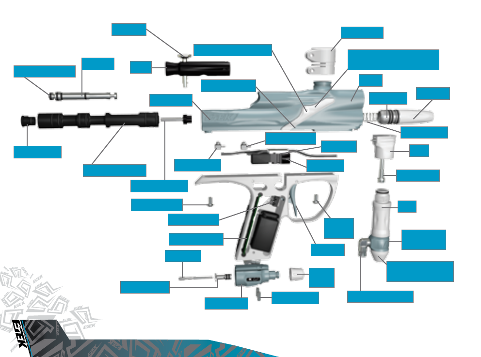
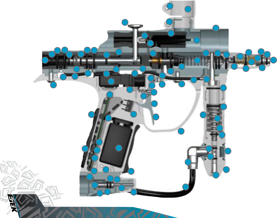
6. ORIENTATION
This section names the component parts of the Etek2 Marker. This
section is essential reading for everyone.
6. > GET TO KNOW YOUR ETEK2
8. > THE ETEK2 CONTROL CONSOLE
8. QUICK SET-UP
This section provides details on how to get up and running quickly with
your Etek2. This section is essential reading for everyone.
8. > INSTALLING A BATTERY
9 > SWITCHING ON THE ETEK2.
9 > SWITCHING OFF THE ETEK2.
9 > FIRING THE ETEK2.
9 > USING THE ETEK2 BREAK-BEAM SENSOR SYSTEM
10. USING YOUR ETEK2
This section provides more detailed information on how to use and
interact with the Etek2 via its user interface.
10 > SETTING UP
10 > INSTALLING A PRESET AIR SYSTEM
11 > T-SLOT MOUNTING SYSTEM
11 > MACROLINE HOSING AND ELBOW
12 > INSTALLING AN ADJUSTABLE AIR SYSTEM
13 > ATTACHING A LOADER
13 > SWITCHING ON
14 > THE CONTROL CONSOLE
14 > UNDERSTANDING THE BBSS OPERATION
15 > ADJUSTING YOUR VELOCITY
15 > ADJUSTING YOUR LPR PRESSURE
16. ADVANCED SET-UP
This section contains in-depth information on setting up the Etek2.
16 > SETTING THE TRIGGER
17 > THE TOURNAMENT LOCK
18 > THE SET-UP MENU
19 > MODIFYING A PARAMETER
20 > THE FIRING MODE PARAMETER
20 > MAXIMUM RATE OF FIRE (CAPPED MODES)
20 > MAXIMUM RATE OF FIRE (BBSS DISABLED)
21 > DWELL
21 > DEBOUNCE
21 > THE BALL DETECTION TIME
21 > THE RESET PARAMETER
22. MAINTENANCE
This section acts as a guide to performing routine maintenance.
22 > CLEANING THE BREAK-BEAM SENSOR SYSTEM
24 > CLEANING THE INLINE REGULATOR
26 > CLEANING THE LPR
28 > CLEANING AND LUBRICATING THE RAMMER
30 > HOW TO STRIP THE ETEK2
32 > ASSEMBLING THE ETEK2
35 > CLEANING THE BOLT
36 > STRIPPING AND CLEANING THE SOLENOID

VISIT WWW.PLANETECLIPSE.COM
VISIT WWW.PLANETECLIPSE.COM
5
CONTENTS
38. FAULT FINDING
This section provides information on how to resolve any problems that
might arise with your Etek2.
42. SERVICE CENTRES
This section provides information on the location of your nearest Eclipse
Service Centre.
44. PARTS LIST
This section provides a table of components that make up the Etek2.
51. WARRANTY CARD
Tear-out product registration card to be completed and returned to
Planet Eclipse. Alternatively register online at
WWW.PLANETECLIPSE.COM
48. ACCESSORIES
Available upgrade / repair kits for your Etek2.
VISIT WWW.PLANETECLIPSE.COM
ORIENTATION
6
VISIT WWW.PLANETECLIPSE.COM
BOLT PIN
RAMMER HOUSING
SENSOR COVER SCREW
FEED NECK
FRAME SCREW
CIRCUIT BOARD
SENSOR COVER BODY
LPR BODY LPR CAP
FRM
FRM SCREW
FRAME
SCREW
TRIGGER
RAMMER CAP
EXHAUST VALVE
TOP
MACROLINE ELBOW
OOPS
KNOB
OOPS BODY
SOLENOID
MINIFOLD
FRONT ELBOW
REAR ELBOW
ETEK LOGO
MAIN SPRING
BREAK-BEAM SENSOR
SYSTEM (UNDER COVER)
BOLT
RAMMER
OOPS INSERT
OOPS PIN
MICRO SWITCH
OOPS SCREW
SWIVEL
COLLAR
INLINE REGULATOR
BOTTOM
RAMMER BUMPER
VISIT WWW.PLANETECLIPSE.COM
VISIT WWW.PLANETECLIPSE.COM
7
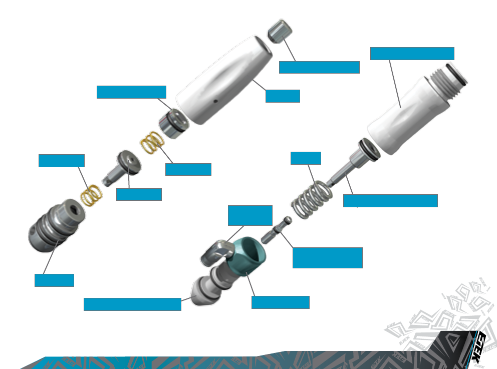
ORIENTATION
LPR PISTON
LPR SPRING
INLINE REGULATOR TOP
LPR SPRING
LPR BODY
INLINE REGULATOR PISTON
INLINE REGULATOR
ADJUSTER SCREW
SWIVEL COLLAR
INLINE REGULATOR BOTTOM
MACROLINE
ELBOW
SPRING
LPR CAP
LPR ADJUSTER SCREW
ADJUSTER PISTON
VISIT WWW.PLANETECLIPSE.COM
ORIENTATION
8
VISIT WWW.PLANETECLIPSE.COM
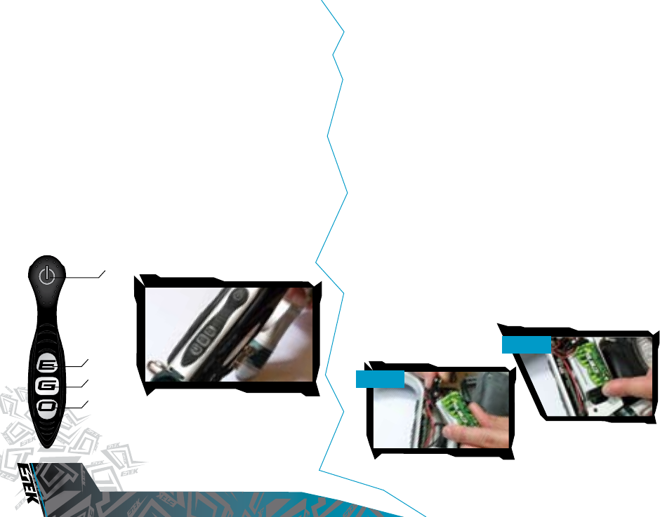
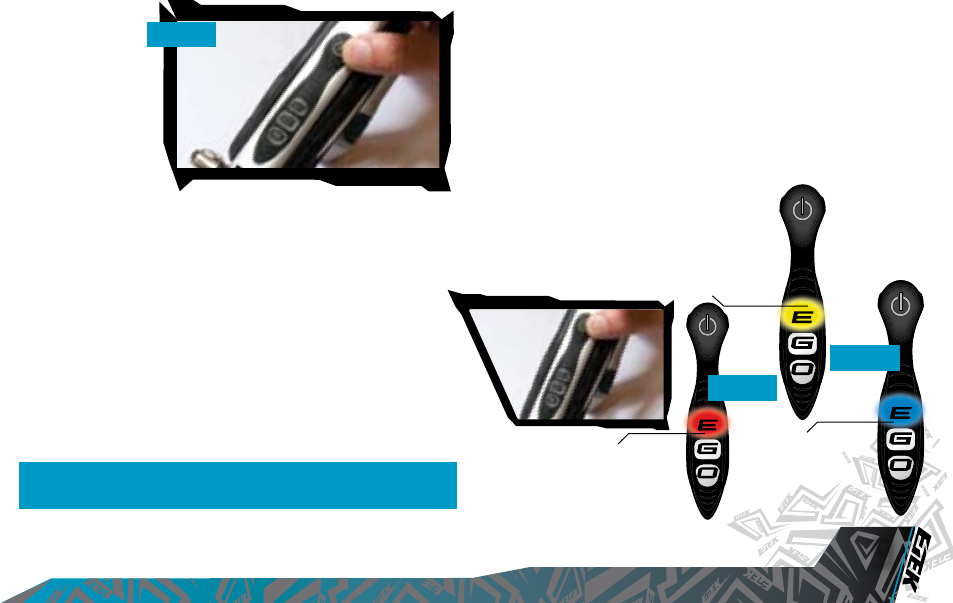
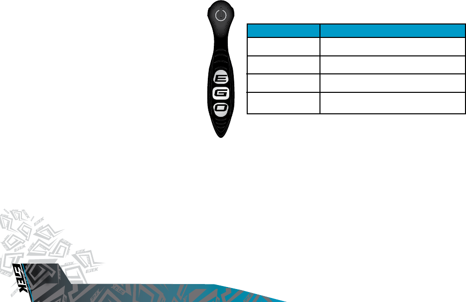
THE ETEK2 CONTROL CONSOLE
At the rear of the Etek2’s grip frame you will find both the Select push
button and three alphabetic LED covers which combine to form the
Etek2’s Control Console. The Control Console is used for several different
purposes including:
- TURNING THE ETEK2 ON AND OFF USING THE
SELECT PUSHBUTTON.
- DISPLAYING THE VALUE OF PARAMETERS USING THE UID.
- SELECTING AND EDITING PARAMETERS USING THE
SELECT PUSHBUTTON.
- DISPLAYING THE BATTERY LEVEL.
- TURNING THE ETEK BBSS ON AND OFF USING THE
SELECT PUSHBUTTON.
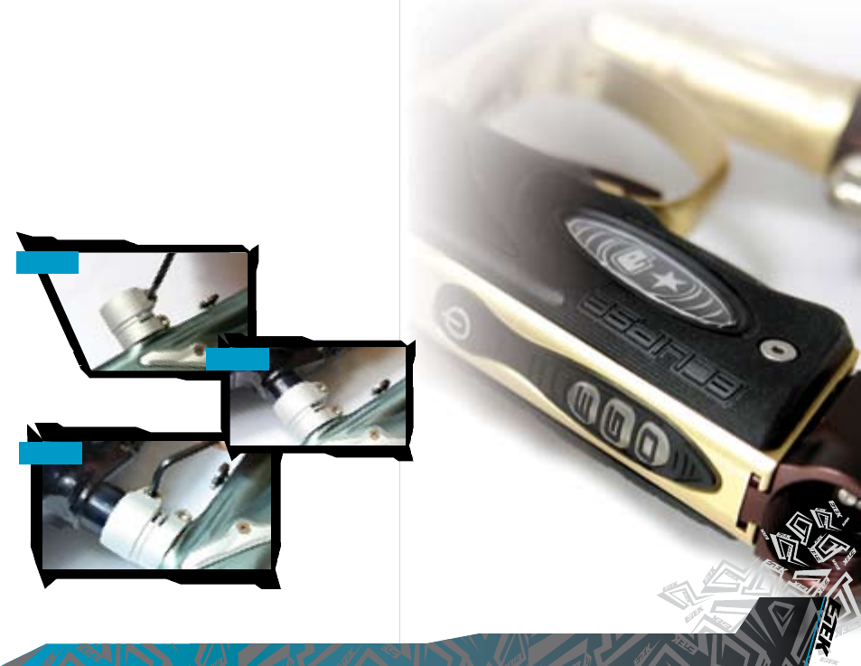
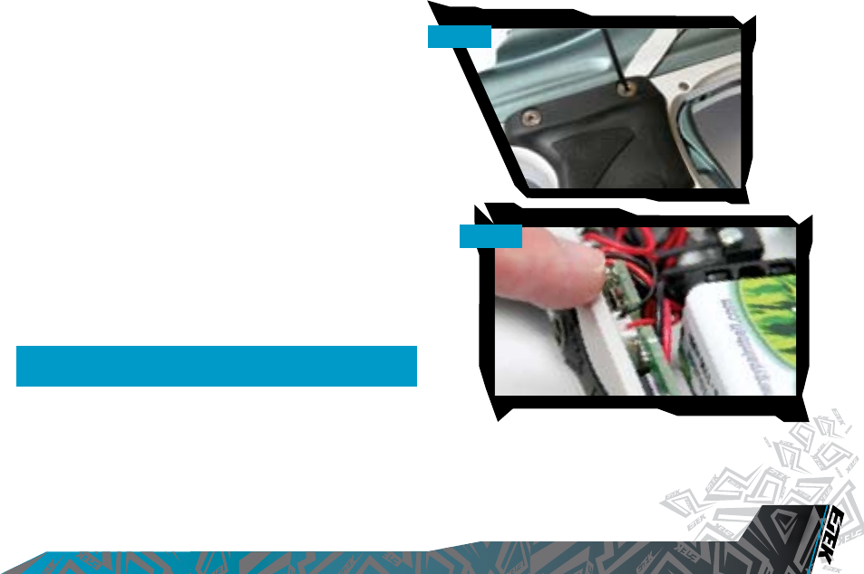
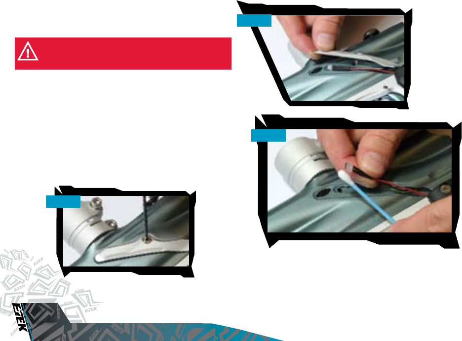
INSTALLING A BATTERY
Ensure that the Etek2 is switched off. Place the marker on a flat surface
in front of you with the feed tube furthest away from you and the barrel
pointing to the right.
Using a 5/64th” (2mm) hex key, remove the three countersunk screws that
holds the rubber grip onto the grip frame. Peel the rubber grip to the right
to expose the electronics within the grip frame.
If present remove the existing 9 volt battery by sliding your thumb into the
recess provided below the battery and lever the battery gently out of the
frame
[SEE FIGURE 2.1].
On top of the battery you will see the battery connector and wire that
is used to connect the battery to the circuit board. Gently separate the
battery connector from the battery, so that the existing battery can be
disposed of accordingly and taking a new 9 volt Alkaline battery (type
PP3, 6LR61, MN1064) connect it to the battery connector
(SEE FIGURE
2.2)
. Note: The battery will only connect to the battery connector one
way. If you are unsure of how to install a new battery please contact your
nearest Eclipse Service Centre.
Ensure that all of the wires are within the recess of the frame and then
replace the rubber grip and tighten the countersunk grip screws using the
5/64th” (2mm) hex key.
DO NOT OVER-TIGHTEN THE SCREWS. FIG 2.1
FIG 2.2
SELECT BUTTON
TOP LED
MIDDLE LED
BOTTOM LED
VISIT WWW.PLANETECLIPSE.COM
VISIT WWW.PLANETECLIPSE.COM
9
QUICK SET-UP
SWITCHING ON THE ETEK2
At the rear of the grip frame is the Control Console. Press and hold the
Select Pushbutton
[SEE FIGURE 2.3]
. Release the Select Pushbutton
when the LED light
up and your Etek2
will begin its power
up sequence.
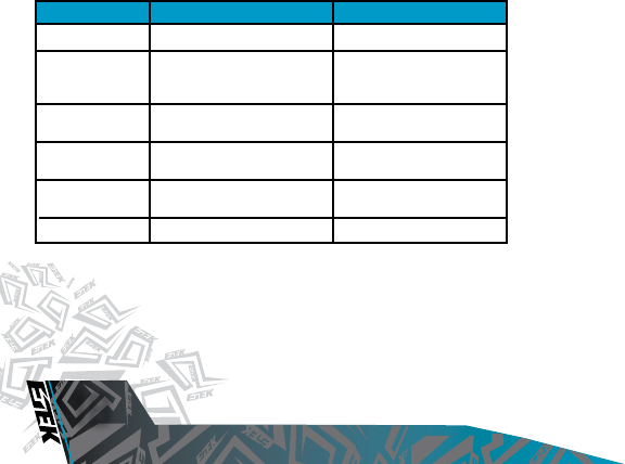
SWITCHING OFF THE ETEK2
Press and hold the Select push button. Release the Select push button
when all three of the LEDs on the control console turn red. The LEDs will
extinguish one by one and the Etek2 will turn off.
FIRING THE ETEK2
If the Break Beam Sensor System is disabled, pull the trigger to fire
the Etek2. If the Break Beam Sensor System is enabled and there is a
paintball in the breech, pulling the trigger will also fire the Etek2. The entire
firing sequence is controlled electronically by the Etek2 circuit board and
solenoid, enabling any user to achieve high rates of fire easily.
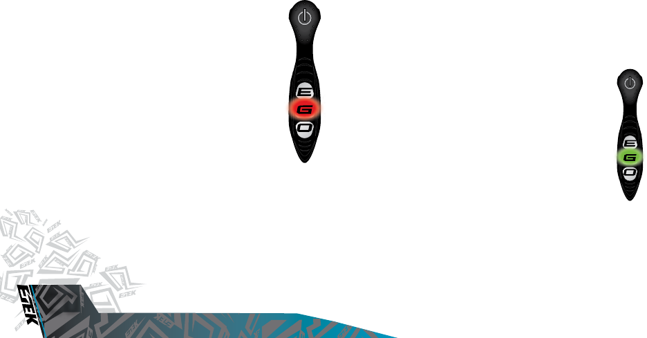
USING THE BREAK BEAM SENSOR
SYSTEM (BBSS)
When the Etek2 is powered up, the Break Beam Sensor System (BBSS)
is automatically enabled.
To switch off the Break Beam Sensor System, push and hold the Select
pushbutton for 0.5 seconds. The “E” on the Control Console will flash red
indicating that the Break Beam Sensor System has been disabled
[SEE
FIGURE 2.4]
.
To switch on the Break Beam Sensor System, push and hold the
Select pushbutton for 0.5 seconds. The “E” on the Control Console will
flash either yellow (no ball detected) or blue (ball detected) indicating that
the Break Beam Sensor System has been enabled
[SEE FIGURE 2.5]
.
Additional features of the Etek2s Break Beam
Sensor System are covered in full in the
“Understanding the BBSS Operation” section
on Page 14 of this User Manual.
NOTE: WHEN TURNING ON THE ETEK2, THE BREAK-BEAM SENSOR
SYSTEM IS AUTOMATICALLY ENABLED.
FIG 2.3
YELLOW LIGHT -
NO BALL DETECTED.
BLUE LIGHT -
BALL DETECTED.
FIG 2.4
RED LIGHT -
BBSS DISABLED.
FIG 2.5
VISIT WWW.PLANETECLIPSE.COM
USING YOUR ETEK2
10
VISIT WWW.PLANETECLIPSE.COM
SETTING UP
Before you can begin to use your Etek2, there are a few necessary
components that are required to enable the Etek2 to function; namely an
air system and a loader of your choice.
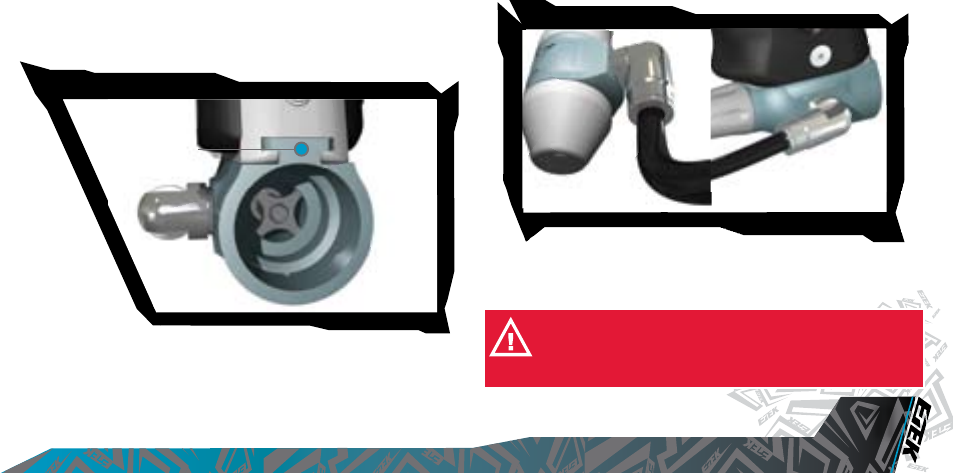
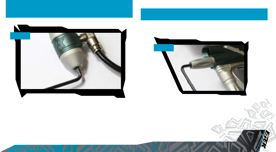
INSTALLING A PRESET
AIR SYSTEM
Every Etek2 comes complete with an Eclipse On/Off Purge System
(OOPS) allowing a preset regulator and tank to be screwed straight in
for immediate use. Before
screwing the preset into
the OOPS ensure that
the On/Off knob is wound
out approximately half
way [SEE FIGURE 3.1].
Be careful not to unscrew
the On/Off knob too far
as it will come completely
out of the OOPS. If this
happens, replace the
On/Off knob by screwing it
back into the OOPS body in a clockwise direction.
Screw the preset air system into the OOPS System [SEE FIGURE 3.2] so that
the bottle screws in all the way and is tight. Slowly turn the On/Off knob in
a clockwise direction allowing the On/Off knob System to depress the pin
of the preset air system causing the Etek2 to become pressurized,
providing that there is sufficient air in your tank [SEE FIGURE 3.3].
You have now installed a preset air system onto your Etek2.
NOTE: THE ETEK2 CANNOT BE USED WITH CO2, IT CAN ONLY BE
POWERED BY COMPRESSED AIR OR NITROGEN.
FIG 3.2
FIG 3.3
FIG 3.1
VISIT WWW.PLANETECLIPSE.COM
VISIT WWW.PLANETECLIPSE.COM
11
USING YOUR ETEK2
T-SLOT MOUNTING SYSTEM
The current industry standard Dovetail rail that is used to connect the
ASA to the frame has consistently proved to be the weakest link for
every manufacturer out there when it comes to the durability of the
system used to mount the tanks to the guns. For that reason we have
shunned the flawed design of the dovetail in favour of a new T-Slot
design. By using a T-shaped slide rail, as opposed to the double V of the
old fashioned dovetail, the ASA-To-Frame interface has been drastically
strengthened. There should be no way that a well executed dive into a
bunker should dislodge the ASA now, but even if you feel you have to
go and use a different ASA there are still standard mounting holes in the
frame to fit your own inferior rail and ASA.
MACROLINE HOSING AND ELBOWS
To aid the longevity of your Macroline hosing, it is very important to
remove it from (and install it back into) the fittings in the correct manner:
Pull back the collet section of the Macroline fitting and keep the collet
depressed.
Pull the Macroline hose out of the Macroline fitting and release the collet.
Before installing the Macroline hose into the Macroline fitting ensure that
the end has been trimmed correctly to ensure a tight fit in the fitting.
WARNING: IF YOU EVER REMOVE THE MACROLINE HOSE
FROM THE FITTING, ALWAYS CHECK THE CONDITION OF YOUR
MACROLINE HOSING AND IF IT IS WORN OR THE WRONG LENGTH
REPLACE IT IMMEDIATELY.
T-SLOT MOUNT
VISIT WWW.PLANETECLIPSE.COM
USING YOUR ETEK2
12
VISIT WWW.PLANETECLIPSE.COM
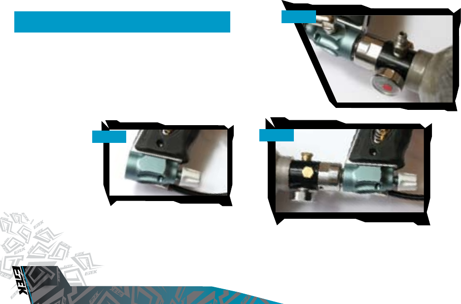
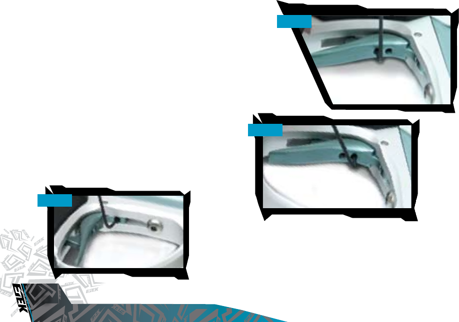
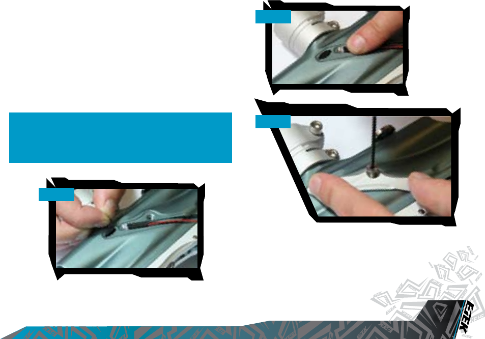
INSTALLING AN ADJUSTABLE AIR
SYSTEM
Firstly disconnect the 1/4” Macroline hosing from the elbow attached to
the OOPS at the base of the grip frame
(SEE FIGURE 3.4)
.
Using a 3/32” hex key loosen the two set screws that tighten the OOPS
body onto the bottom of the grip frame
(SEE FIGURE 3.5)
. The OOPS
body can now be removed from the T-Slot Rail on the bottom of the grip
frame by sliding it backwards
(SEE FIGURE 3.6)
to expose the base of
the frame.
As well as the integrated slide rail at the base of the Etek2s grip frame,
there are also two 10-32 UNF threaded screw holes which will accept
standard bottom line screws
(SEE FIGURE 3.7)
.
Attach the air system of your choice, taking care to use the correct fittings
and length and size of hose to accommodate your requirments.
.
FIG 3.4
FIG 3.5
FIG 3.6
NOTE: WHEN USING AN OOPS ON YOUR ETEK2, THE ETEK2 WILL STILL
HAVE STORED AIR IN THE VALVE CHAMBER, GAS LINE AND INLINE
REGULATOR AFTER YOU HAVE TURNED THE OOPS OFF. PLEASE
REMEMBER TO DISCHARGE THE STORED AIR IN A SAFE DIRECTION AS
YOU ARE UNSCREWING THE ON/OFF KNOB ON THE OOPS.
FIG 3.7
VISIT WWW.PLANETECLIPSE.COM
VISIT WWW.PLANETECLIPSE.COM
13
USING YOUR ETEK2
ATTACHING A LOADER
Using a 5/32” hex key, turn the top screw of the feed tube counter
clockwise until the feed neck of your loader can easily be pushed into the
top of the feed tube (SEE FIGURE 3.8). Push your choice of loader firmly into
the feed tube so that it rests on the shelf inside the feed tube (SEE FIGURE
3.9). Using a 5/32” hex key, tighten the top screw of the feed tube by
turning it clockwise until the loader is firmly gripped (SEE FIGURE 3.10).
You have now attached a loader to your Etek2. Once you have filled your
loader and air tank you will then be ready to begin using your Etek2.
SWITCHING ON
Pressing and holding the Select pushbutton will switch the Etek2 on.
Release the Select pushbutton when the UID lights up and your Etek2
will begin its power up sequence.
FIG 3.8
FIG 3.9
FIG 3.10
VISIT WWW.PLANETECLIPSE.COM
USING YOUR ETEK2
14
VISIT WWW.PLANETECLIPSE.COM
THE CONTROL CONSOLE
The Etek2 utilises multi coloured LEDs to display all of the information
that the user requires via the Etek2s Control Console.
Each area of the Control Console is used to perform different
functions and display different information as outlined below:
The Select Pushbutton is used to:
- Switch the Etek2 On and Off.
- Switch the BBSS (eye system) On and Off.
- To scroll through parameters and edit parameters.
The “E” on the Control Console is used to:
- Display the status of the BBSS (eye system).
- Display the value of a parameter in Tens (10 - 90)
The “G” on the Control Console is used to:
- Display the value of a parameter in Units (0 - 9)
- Display the status of the battery.
The “O” on the Control Console is used to:
- Display the value of a parameter in Tenths (0.0 - 0.9)
As a combined unit the “E”, “G” and “O” are also used to:
- Display power up and power down status.
- Display tournament lock status.
- Display that Factory settings have been restored
- To confirm whether a parameter value has been accepted or rejected.
UNDERSTANDING THE BBSS
OPERATION
The Etek2 displays the status of the Break Beam Sensor System using
the “E” area of the Control Console as follows:
Any changes to the Breech Sensor Status will be displayed immediately.
This provides valuable feedback to the user.
An example of this is when you are shooting a string of shots with the
BBSS enabled, the “E” on the Control Console will alternate in colour
from Yellow (no paintball detected) to Blue (paintball detected). In this
instance too much yellow would indicate that your chosen loader cannot
keep up with how fast you are shooting and is consequently slowing
down your rate of fire.
The BBSS is able to switch itself off in the event that a blockage or
contamination prevents it from functioning correctly.This is represented
by a double flashing red light in the “E” area of the Control Console. The
Etek’s ROF will be capped at 10bps. In this instance, the BBSS will switch
itself back on once the blockage is cleared and the correct operation of
the BBSS can then be resumed.
INDICATION BREECH SENSOR STATUS
Flashing Yellow BBSS enabled (On), no paintball detected
- marker will not fire.
BBSS enabled (On), paintball detected
- marker will fire.
BBSS disabled (Off) - marker will fire.
Blockage detected, BBSS temporarily
disabled (Off) - marker will fire.
Flashing Blue
Flashing Red
Double Flashing Red
VISIT WWW.PLANETECLIPSE.COM
VISIT WWW.PLANETECLIPSE.COM
15
USING YOUR ETEK2
ADJUSTING YOUR VELOCITY
When using your Etek2, you may wish to change the velocity at which
your Etek2 is firing. This is done by inserting a 1/8" hex key into the
adjuster screw at the bottom of your Etek2 Inline regulator and adjusting
it accordingly (SEE FIGURE 3.11). By turning this adjuster screw clockwise you
decrease the output pressure of the inline regulator and consequently the
velocity, by turning the adjuster screw counter clockwise you increase
the output pressure of the inline regulator and consequently the velocity.
ADJUSTING YOUR LPR PRESSURE
When using your Etek2, you may wish to change the output pressure of
your LPR. This is easily done by inserting a 5/32" inch hex key into the
adjuster screw at the front and adjusting it accordingly (SEE FIGURE 3.12).
By turning the adjuster screw clockwise, you decrease the output
pressure of your LPR and consequently reduce the pressure driving your
rammer back and forth. By turning the adjuster screw counter clockwise,
you increase the output pressure of your LPR and consequently increase
the pressure driving your rammer back and forth.
NOTE: AFTER EACH ADJUSTMENT FIRE AT LEAST TWO CLEARING
SHOTS TO GAIN AN ACCURATE VELOCITY READING. NEVER EXCEED
300FPS. NOTE: TURNING THE ADJUSTER SCREW OUT TOO FAR WILL CAUSE
IT TO FALL OUT.
FIG 3.11
FIG 3.12
VISIT WWW.PLANETECLIPSE.COM
ADVANCED SET-UP
16
VISIT WWW.PLANETECLIPSE.COM
SETTING THE TRIGGER
There are three adjustment points on the trigger – the Front Stop Trigger
Screw, the Rear Stop Trigger Screw, and the Spring Tension Screw.
As standard each Etek2 comes with a factory set trigger travel of
approximately 2mm in total length; one millimeter of travel before the
firing point and one millimeter of travel after the firing point.
The Front Stop Trigger Screw is used to set the amount of trigger travel
prior to the marker firing. Turn this screw clockwise to reduce the amount
of travel. Do not turn the screw too far or the trigger will be pushed past
the firing point and the marker will not work. Turn this screw counter
clockwise to increase the amount of trigger travel [SEE FIGURE 4.1].
The Rear Stop Trigger Screw is used to set the amount of travel after
the marker has fired. Turn this screw clockwise to reduce the amount
of travel. Do not turn the screw too far or the trigger will be prevented
from reaching its firing point and the marker will not work. Turn this screw
counter clockwise to increase the amount of travel [SEE FIGURE 4.2).
The Spring Tension Screw is used to adjust the amount of spring tension
behind the trigger when it is pulled. Turn the screw clockwise to increase
the amount of spring tension. Turn the screw counter clockwise to
reduce the amount of spring tension [SEE FIGURE 4.3].
FIG 4.1
FIG 4.2
FIG 4.3
VISIT WWW.PLANETECLIPSE.COM
VISIT WWW.PLANETECLIPSE.COM
17
ADVANCED SET-UP
THE TOURNAMENT LOCK
The Etek2 has an electronic tournament lock which, once enabled,
prevents the user from making any changes to the operating parameters
of the marker. This tournament lock complies with the rules of all major
tournaments and must be enabled prior to entering the field of play in
order to avoid penalties.
To enable the tournament lock -
1. Unscrew the three screws from the right hand side of the rubber grips
(SEE FIGURE 4.4)
using a 5/64” hex key.
2. Turn on the Etek2.
3. Locate and press the Lock pushbutton on the circuit board
(SEE FIGURE 4.5)
. The Control Console will flash green to indicate that
the tournament lock has been enabled.
4. Replace the three rubber grip screws using a 5/64” hex key.
To disable the tournament lock –
1. Unscrew the three screws from the right hand side of the rubber grips
(SEE FIGURE 4.4)
using a 5/64” hex key.
2. Turn on the Etek2.
3. Locate and press the Lock pushbutton on the circuit board
(SEE FIGURE 4.5)
. The Control Console will flash red to indicate that
the tournament lock has been disabled.
4. Replace the three rubber grip screws using a 5/64” hex key.
NOTE: THE ETEK2 IS SHIPPED WITH THE TOURNAMENT LOCK
DISABLED.
FIG 4.4
FIG 4.5
VISIT WWW.PLANETECLIPSE.COM
ADVANCED SET-UP
18
VISIT WWW.PLANETECLIPSE.COM
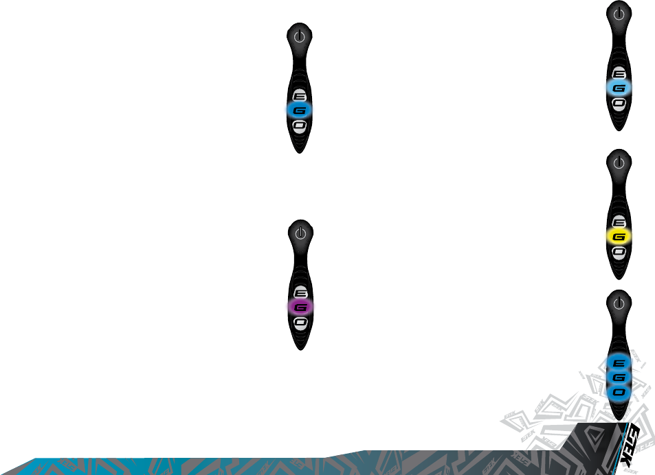
THE SET UP MENU
The Set Up Menu can only be entered if tournament lock is off.
To activate the Set Up Menu, firstly ensure that the Etek2 is switched
off. Pull and hold the trigger, and whilst the trigger is still pulled push
and hold the Select pushbutton until the “E” and the “O” on the Control
Console alternately flash white to indicate entry to Set Up mode. When
you have entered the Set Up Menu, the “G” on the Control Console will
turn red to indicate the first parameter of the Set Up Menu: The Firing
Mode. You can now release the trigger.
Press the select pushbutton to scroll through each of the parameters on
the Set Up Menu:
To display a parameter value, pull and release the trigger. The value of the
currently selected parameter is indicated by the “E”, “G” and “O” on the
Control Console flashing in turn, top to bottom. Each letter represents one
digit of the value as follows:
For example a value of 14.5 would be displayed as:
- One flash of the “E”, followed by
- Four flashes of the “G”, followed by
- Five flashes of the “O”.
If a digit is zero then this is represented by no flashes on the area of the
Control Console that represents that digit. For example a value of 3.0
would be displayed as:
- No flashes of the “E”, followed by
- Three flashes of the “G”, followed by
- No flashes of the “O”.
COLOUR PARAMETER RANGE
Red
Green
Blue
Magenta
( Purple)
Cyan
(Light Blue)
Yellow
Firing Mode
Maximum ROF with
Breech Sensor (for capped
modes only)
Dwell
Debounce
Ball Detection Time
1 to 5
10.0 bps to 15.4 bps
10.0 bps to 15.4 bps
1.0 ms to 15.0 ms
1 to 10
1 ms to 10 ms
Maximum ROF without
Breech Sensor

VISIT WWW.PLANETECLIPSE.COM
VISIT WWW.PLANETECLIPSE.COM
19
ADVANCED SET-UP
MODIFYING A PARAMETER
You can modify a parameter by using the following guidelines.
1. Ensure that you are in Set Up mode (see previous page).
2. Choose the parameter that you wish to modify.
3. Pull and hold the trigger. The value of the currently selected parameter
is indicated by flashing the three letters on the Control Console as
previously described.
4. When the sequence is complete, the “E” on the Control Console is
illuminated. Release the trigger.
5. Pull the trigger up to nine times to set the tens digit. DO NOT pull the
trigger if the required digit is zero.
6. Push the Select pushbutton. The “G” on the Control Console is
illuminated.
7. Pull the trigger up to nine times to set the units digit. DO NOT pull the
trigger if the required digit is zero.
8. Push the Select pushbutton. The “O” on the Control Console is
illuminated.
9. Pull the trigger up to nine times to set the tenths digit. DO NOT pull
the trigger if the required digit is zero.
10. Push the Select pushbutton. The “E”, “G” and “O” will flash three
times; if the colour is green then the value has been accepted, if the
value is red then the value has been rejected.
If the value is accepted, it will then be saved as the new value for that
parameter.
If the value is rejected, then the parameter will remain unchanged from
how it was before you began modifying it.
Note: To leave a parameter unchanged having already started to modify
it, simply set an illegal value (00.0 or any single digit greater than 9) and
the value will consequently be rejected.
VISIT WWW.PLANETECLIPSE.COM
ADVANCED SET-UP
20
VISIT WWW.PLANETECLIPSE.COM
THE FIRING MODE PARAMETER.
The Firing Mode Parameter is used to control the firing mode of the
Etek2. The Firing Mode Parameter is displayed by a Red light on
the Control Console when you are in the Set Up Menu. There are
five selectable Firing Modes on the Etek2. Each of the selectable
firing modes has its own features as outlined below:
SEMI 1
(Mode 1 on the Firing Mode Parameter)
This is the default firing mode which produces one shot for every pull
of the the trigger. This mode is uncapped with the Break Beam Sensor
System (BBSS) enabled.
SEMI 2
(Mode 2 on the Firing Mode Parameter)
This mode is the same as Semi 1 mode, except for the fact that
the rate of fire is capped at the MAX ROF setting (bps).
RAMP 1
(Mode 3 on the Firing Mode Parameter)
This mode allows the rate of fire to ramp to a maximum set by
the Maximum Rate of Fire with BBSS enabled parameter, once
the trigger has been pulled four times at a minimum rate of 5
pps (pulls per second), and allows this rate of fire to maintained
as long as the required trigger pull rate is maintained. After the
last trigger pull, the ramp can be restarted with a single trigger
pull if that pull occurs within one second.
RAMP 2
(Mode 4 on the Firing Mode Parameter)
This mode is the same as Ramp 1 mode but without the one second
ramp restart.
RAMP 3
(Mode 5 on the Firing Mode Parameter)
This mode is the same as Ramp 2 mode but activates at a minimum rate
of 7.5 pulls per second.
RAMP 4
(Mode 6 on the Firing Mode Parameter)
This mode is the same as Ramp 1 but with a maximum rate of fire of
13bps. This mode is compliant with the 2008 PSP rules covering firing
modes, provided that the Maximum ROF parameter remains
unchanged.
RAMP 5
(Mode 7 on the Firing Mode Parameter)
This mode is the same as Ramp 2 but with a maximum rate of fire of
12bps
and a ramp activation point of 6.0 pulls per second. This mode is
compliant with the 2008 Millennium Series rules covering firing modes,
provided that the Maximum ROF parameter remains unchanged.
Please Note: Certain modes may only be available in certain countries
and on certain models of the Etek2s.
THE MAXIMUM RATE OF FIRE
(CAPPED MODES).
The Maximum Rate of Fire in capped modes is used to control
how fast the Etek2 can cycle in each of the capped firing
modes; Semi 2, Ramp 1, Ramp 2 and Ramp 3.
The Maximum Rate of Fire (capped modes) Parameter is
displayed by a Green light on the Control Console when you
are in the Set Up Menu.
This is fully adjustable between 10.0 balls per second and 15.4
balls per second in 0.1 bps increments.
VISIT WWW.PLANETECLIPSE.COM
VISIT WWW.PLANETECLIPSE.COM
21
ADVANCED SET-UP
THE MAXIMUM RATE OF FIRE
(BBSS DISABLED).
The Maximum Rate of Fire with the BBSS disabled is used to
control how fast the Etek2 cycles when the Break Beam Sensor
System has been disabled.
The Maximum Rate of Fire (BBSS disabled) Parameter is
displayed by a Blue light on the Control Console when you are
in the Set Up Menu.
This parameter is fully adjustable between 10.0 balls per
second and 15.4 balls per second in 0.1 bps increments.
This parameter should be set to match the slowest speed of the loading
system in use.
DWELL.
The Dwell Parameter controls the amount of time that the
solenoid is energised and therefore the amount of gas that is
released with each shot.
The Dwell Parameter is displayed by a Purple light on the
Control Console when you are in the Set Up Menu.
This parameter is fully adjustable between 1.0ms and 15.0ms in
0.1ms increments.
DEBOUNCE.
The Debounce Parameter is used to set the level of Debounce
(anti-bounce) on your Etek2.
The Debounce Parameter is displayed by a Light Blue light on
the Control Console when you are in the Set Up Menu.
This parameter is fully adjustable between Debounce 1 and
Debounce 10 with Debounce 1 allowing the most bounce and
Debounce 10 the least.
THE BALL DETECTION TIME.
The Ball Detection Time Parameter defines how long a paintball
has to sit in the breech of the Etek2 before it is considered ready
to fire.
The Ball Detection Time Parameter is displayed by a Yellow light
on the Control Console when you are in the Set Up Menu.
This parameter is fully adjustable between 1 ms and 10 ms in 1
ms increments.
THE RESET PARAMETER.
Whilst in Set Up Mode, it is possible to reset all of the control
parameters to the factory default settings in the following way:
1. Push and hold the Lock pushbutton
(SEE FIGURE 4.5)
2. The “E”, “G” and “O” on the control will repeatedly flash
blue to indicate that the factory default settings have been
restored.
3. Release the Lock pushbutton.
VISIT WWW.PLANETECLIPSE.COM
MAINTENANCE
22
VISIT WWW.PLANETECLIPSE.COM
CLEANING THE BREAK-BEAM
SENSOR SYSTEM
Undo the retaining screw for the Break-Beam Sensor Cover on the left
hand side of the Etek2 using a 5/64" hex key (SEE FIGURE 5.1)(See Figure
6.1)
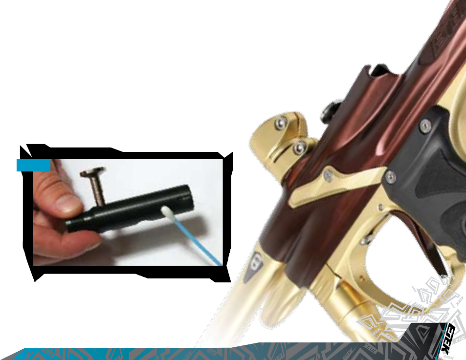
Remove the Sensor Cover to expose the back of the Break-Beam Sensor
unit (SEE FIGURE 5.2). Using a dry Q-tip, carefully remove any debris, paint
or moisture from the back of the sensor unit and from inside the Sensor
Cover.
Carefully lift the sensor unit free from the Etek2 body and using another
dry Q-tip, remove any grease or debris build-up from the front of the
sensor unit (SEE FIGURE 5.3).
WARNING: DE-GAS YOUR MARKER, DISCHARGING ANY STORED
GAS IN A SAFE DIRECTION, AND REMOVE THE BARREL AND
LOADER TO MAKE THE ETEK2 EASIER TO WORK ON.
FIG 5.1
FIG 5.2
FIG 5.3
VISIT WWW.PLANETECLIPSE.COM
VISIT WWW.PLANETECLIPSE.COM
23
MAINTENANCE
Remove the rubber nger detent and using a dry Q-tip clean the detent
and it’s location point in the Etek2 Body. Replace clean detent back into
the Etek2 body (SEE FIGURE 5.4) and install sensor unit back into place (SEE
FIGURE 5.5).
Replace the Sensor Cover and using a 5/64" hex key, replace the Break
Beam Sensor Cover retaining screw to hold the sensor cover in place
(SEE FIGURE 5.6).
BE CAREFUL NOT TO CROSS-THREAD THE SCREW. DO NOT OVER TIGHTEN THE
SCREW.
Repeat procedure for opposite side of the Etek2.
You have now cleaned your Break-Beam Sensor System.
NOTE: WHEN CLEANING BREAK-BEAM SENSOR SYSTEM INSPECT
CONDITION OF RUBBER FINGER DETENTS AND REPLACE IF
NECESSARY. ENSURE THAT THE RECEIVER SENSOR (INDICATED BY
A RED MARK & RED HEAT SHRINK) IS LOCATED ON THE RIGHT-
HAND SIDE OF THE MARKER BODY.
FIG 5.4
FIG 5.5
FIG 5.6

VISIT WWW.PLANETECLIPSE.COM
MAINTENANCE
24
VISIT WWW.PLANETECLIPSE.COM
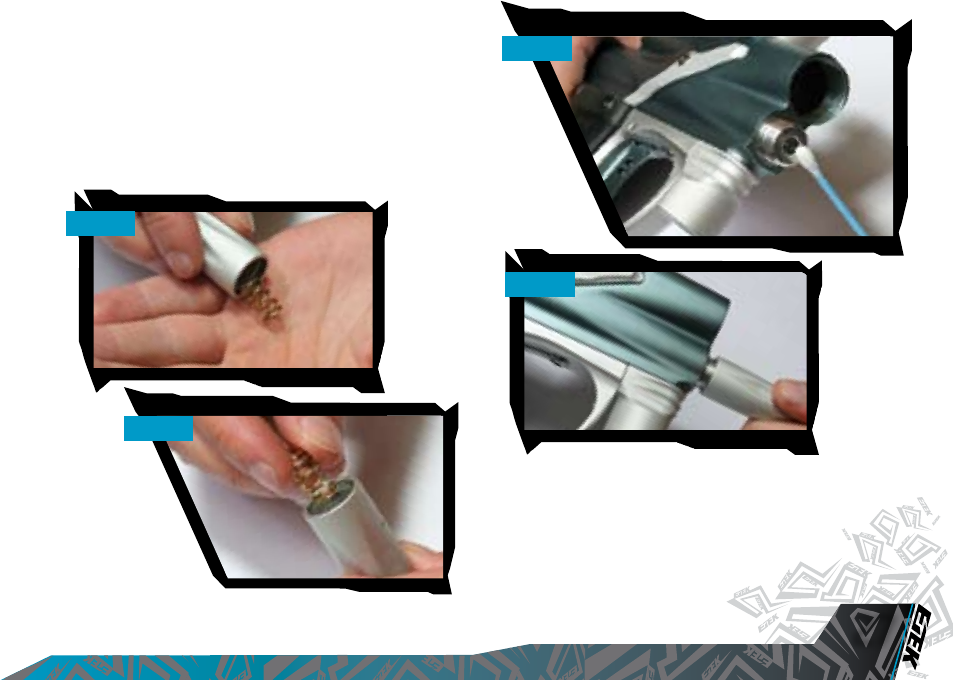
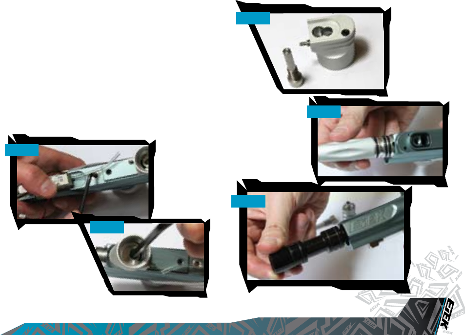
CLEANING THE INLINE
REGULATOR
Disconnect the hosing from your Inline Regulator allowing it to be
unscrewed from the Front Regulator Mount (FRM) (SEE FIGURE 5.7).
Turn the Inline Regulator upside down and carefully unscrew the two
sections, taking care not to lose the spring from inside the regulator (SEE
FIGURE 5.8).
By firmly gripping the exposed end of the aluminium regulator piston,
carefully remove the piston and spring in its entirety (SEE FIGURE 5.9).
Insert a 1/8” hex key into the adjuster screw in the bottom half of the inline
regulator, and wind the screw clockwise through the bottom section of
the regulator body (SEE FIGURE 5.10) and pull free when it will no longer turn
upwards anymore.
WARNING: DE-GAS YOUR MARKER, DISCHARGING ANY STORED
GAS IN A SAFE DIRECTION, AND REMOVE THE BARREL AND
LOADER TO MAKE THE ETEK2 EASIER TO WORK ON.
FIG 5.7
FIG 5.8
FIG 5.9
FIG 5.10
NOTE: THE ADJUSTER SCREW CAN ONLY BE REMOVED BY TURNING
IT UPWARDS THROUGH THE BOTTOM SECTION OF THE INLINE
REGULATOR. THE REGULATOR WILL BECOME DAMAGED IT THE
ADJUSTER SCREW IS REMOVED INCORRECTLY.
VISIT WWW.PLANETECLIPSE.COM
VISIT WWW.PLANETECLIPSE.COM
25
MAINTENANCE
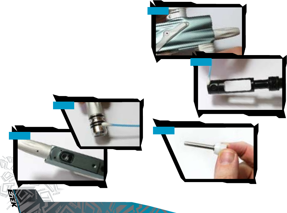
Using a dry Q-tip, clean the seal that sits at the top of the body of the
bottom section of the Inline regulator (SEE FIGURE 5.11). Using a light oil and
a fresh Q-tip, re-lubricate the seal ready for re-assembly.
Thoroughly clean the two o-
rings on the adjuster screw
and lubricate ready for re-
assembly (SEE FIGURE 5.12).
Inspect top face of adjuster
unit for any excessive wear or
damage as this could cause
inline regulator to creep (SEE
FIGURE 5.13).
Note: The sealing face on the inline
regulator piston can also cause the
regulator to creep or “supercharge”,
so this should also be checked.
With the threaded section towards
to the base of the regulator body,
re-insert the adjuster screw into the
bottom half of the regulator body (SEE
FIGURE 5.14). Apply light pressure to the top of the adjuster screw and using
a 1/8th" hex key wind the adjuster screw counter clockwise until it stops
at the base of the regulator body. Turn the adjuster screw five turns in a
clockwise direction to set the inline regulator pressure at approximately
200 psi.
Next take the piston and spring and clean the o-ring at the end of the
piston, re-lubricating it with a light smear of Vaseline ready for re-assembly
(SEE FIGURE 5.15). Insert the piston and spring into the top half of the inline
regulator body (SEE FIGURE 5.16).
Keeping the top half of the inline regulator upside down, screw the two
halves of the inline regulator together (SEE FIGURE 5.17).
You have now stripped, cleaned, lubricated and assembled your inline
regulator.
FIG 5.11
FIG 5.12
FIG 5.13
FIG 5.14
FIG 5.15
FIG 5.16
FIG 5.17
NOTE: IF ANY SEALS ARE DAMAGED, REPLACE AS NECESSARY.
EXTRA SEALS ARE AVAILABLE IN ETEK2 PARTS KITS AVAILABLE
ONLINE AT WWW.PLANETECLIPSE.COM.
VISIT WWW.PLANETECLIPSE.COM
MAINTENANCE
26
VISIT WWW.PLANETECLIPSE.COM
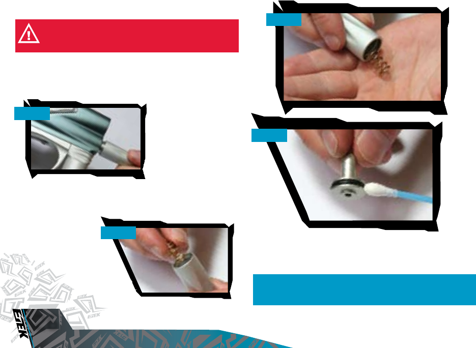
CLEANING THE LPR
The Inline regulator can be removed if needs be.
Unscrew the low-pressure regulator cap from the Etek2 body (SEE FIGURE
5.18).
Remove the LPR piston and
rear spring from the LPR cap
(SEE FIGURE 5.19).
Cupping the palm of one
hand, turn the LPR cap
upside down and tip the front
spring out into your palm (SEE
FIGURE 5.20.
Remove the rear spring from the LPR piston and using a dry Q-tip, carefully
clean the seal on the LPR piston (SEE FIGURE 5.21. If the seal is damaged,
replace as necessary. Once the seal has been cleaned, lubricate with a
light smear of Vaseline, so that it is ready for re-assembly.
WARNING: DE-GAS YOUR MARKER, DISCHARGING ANY STORED
GAS IN A SAFE DIRECTION, AND REMOVE THE BARREL AND
LOADER TO MAKE THE ETEK2 EASIER TO WORK ON.
NOTE: THE ADJUSTER PISTON (COLOURED CAP THAT THE FRONT
SPRING RESTS IN) DOES NOT NEED TO BE REMOVED FROM THE
LPR CAP FOR REGULAR MAINTENANCE.
FIG 5.18
FIG 5.19
FIG 5.20
FIG 5.21
VISIT WWW.PLANETECLIPSE.COM
VISIT WWW.PLANETECLIPSE.COM
27
MAINTENANCE
Insert the front spring into the LPR cap, so that it rests neatly in the ad-
juster piston
(SEE FIGURE 5.22
).
Place the rear spring onto the LPR piston and insert piston and spring into
the LPR cap, o-ring end first (SEE FIGURE 5.23).
Before screwing the LPR cap back onto your Etek2, use a dry Q-tip to
clean the seal inside the LPR body (SEE FIGURE 5.24). Lubricate this seal
using a light 3 in 1 oil.
Replace the LPR cap by screwing it onto the LPR body in the Etek2 (SEE
FIGURE 5.25).
FIG 5.22
FIG 5.23
FIG 5.24
FIG 5.25
VISIT WWW.PLANETECLIPSE.COM
MAINTENANCE
28
VISIT WWW.PLANETECLIPSE.COM
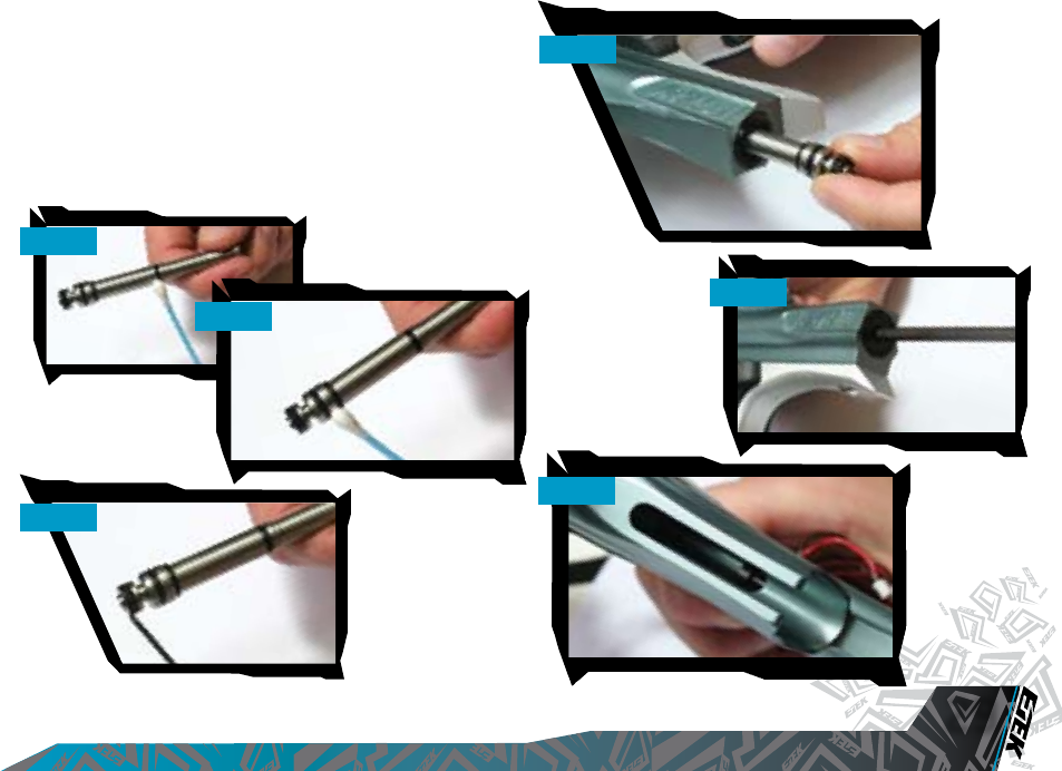
CLEANING AND LUBRICATING THE
RAMMER
Pull the bolt pin upwards so that it dis-engages the rammer, allowing the
bolt to be removed via the rear of the Etek2 (SEE FIGURE 5.26).
Using a 3/16" hex key, unscrew and remove the rammer cap at the rear
of the Etek2 (SEE FIGURE 5.27).
Raise the front of the Etek2 and tap the Etek2 onto your hand until the
rammer falls into the palm of your hand (SEE FIGURE 5.28).
Thoroughly clean the rammer shaft and all of its seals, paying special
attention to the seal on the middle of the shaft (SEE FIGURE 5.29), the rear
seal (SEE FIGURE 5.30) and the condition of the bumper at the rear of the
shaft (SEE FIGURE 5.31). Note: All these pictures are on the next page.
Replace any worn seals/bumpers using authentic Etek2 spare parts.
WARNING: DE-GAS YOUR MARKER, DISCHARGING ANY STORED
GAS IN A SAFE DIRECTION, AND REMOVE THE BARREL AND
LOADER TO MAKE THE ETEK2 EASIER TO WORK ON.
FIG 5.26
FIG 5.27
FIG 5.28
VISIT WWW.PLANETECLIPSE.COM
VISIT WWW.PLANETECLIPSE.COM
29
MAINTENANCE
Lubricate all of the seals on the rammer shaft and replace the rammer into
the rear of the Etek2 body with the bumper at the back (SEE FIGURE 5.32).
Note: Use light paintgun oiL.
Replace the rammer cap, using the 3/16" hex key to secure it into the
Etek2 body (SEE FIGURE 5.33).
Noting the position of the rammer in the Etek2 body (SEE FIGURE 5.34),
replace the bolt and locate the bolt pin into the designated groove in the
rammer shaft.
FIG 5.29
FIG 5.32
FIG 5.33
FIG 5.34
FIG 5.30
FIG 5.31
VISIT WWW.PLANETECLIPSE.COM
MAINTENANCE
30
VISIT WWW.PLANETECLIPSE.COM
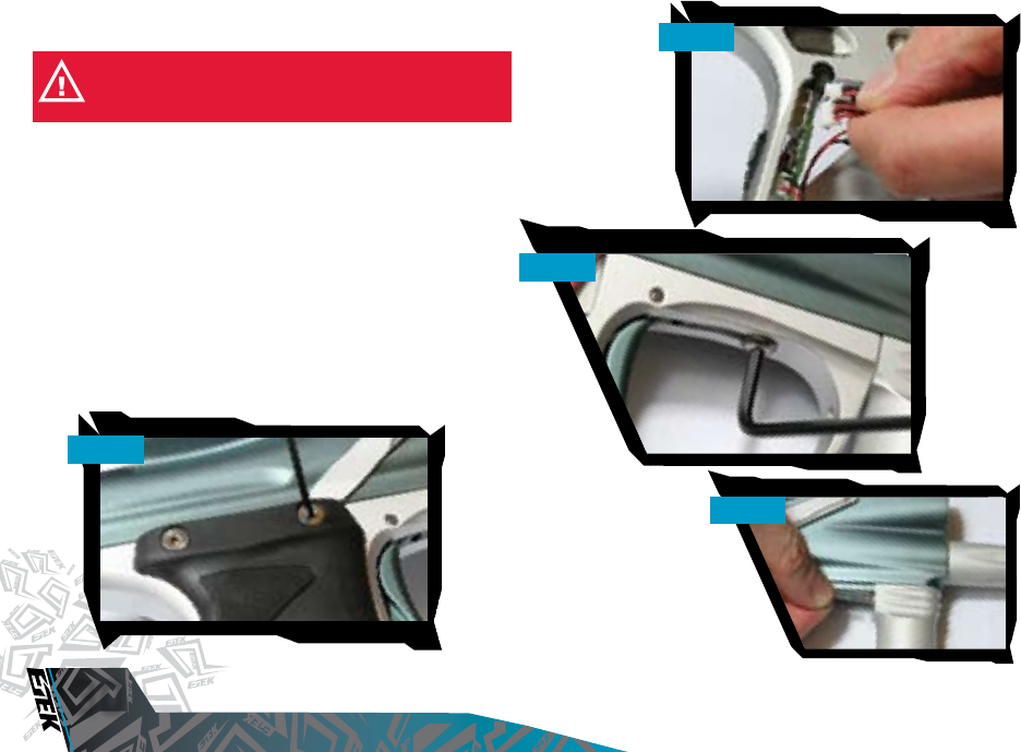
HOW TO STRIP THE ETEK2
Remove the bolt and bolt pin, disconnect any hosing and unscrew the
inline regulator from the front regulator mount as detailed above.
Using a 5/64th" hex key remove the six screws that attach the Etek2 grips
to the Etek2 frame (SEE FIGURE 5.35).
Unplug the solenoid and unplug the Break-Beam sensors from their ports
on the Etek2 printed circuit board (SEE FIGURE 5.36).
Using a 1/8" hex key undo the two frame retaining screws (SEE FIGURE 5.37)
and remove the frame from the Etek2 body, taking care not to damage
any wires.
Free the hose from the barb fitting at the rear of the front regulator mount,
using a pick or other suitable implement (SEE FIGURE 5.38).
WARNING: DE-GAS YOUR MARKER, DISCHARGING ANY STORED
GAS IN A SAFE DIRECTION, AND REMOVE THE BARREL AND
LOADER TO MAKE THE ETEK2 EASIER TO WORK ON.
FIG 5.35
FIG 5.36
FIG 5.37
FIG 5.38
VISIT WWW.PLANETECLIPSE.COM
VISIT WWW.PLANETECLIPSE.COM
31
MAINTENANCE
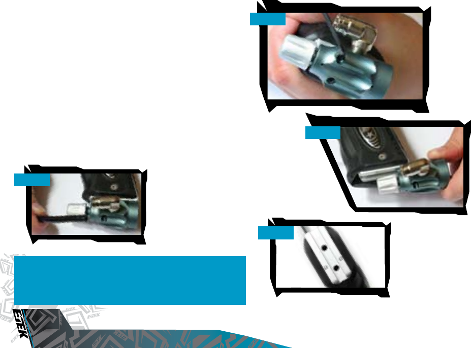
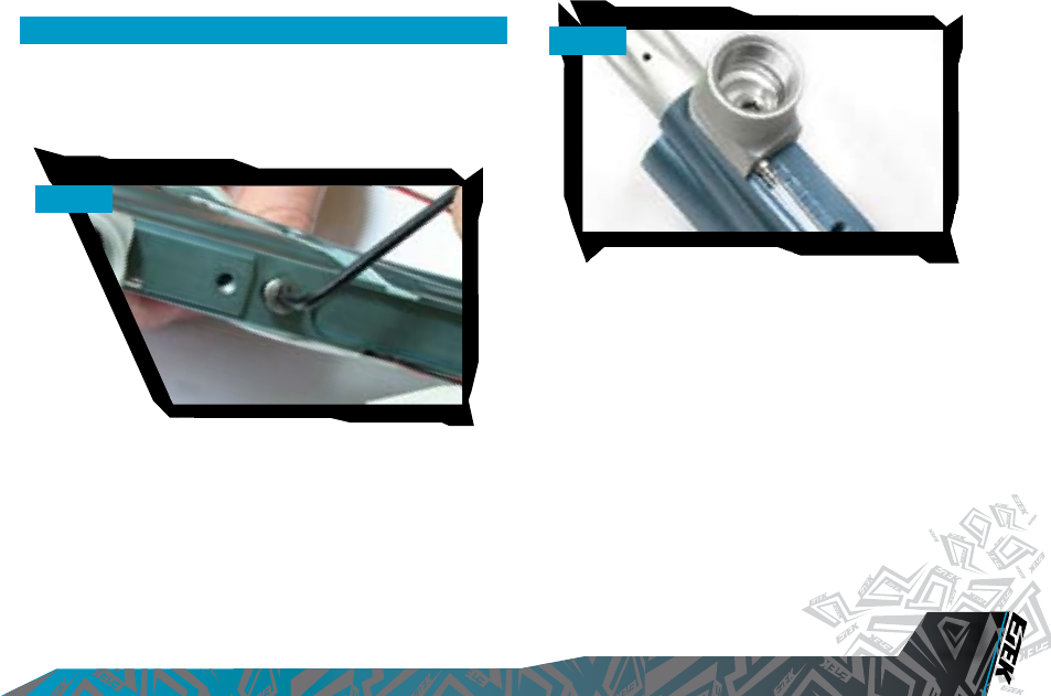
Using a 1/8th" hex key, remove the valve plug from the underside of the
Etek2 body (SEE FIGURE 5.39).
Taking the Etek2 body, turn it so that the underside of the front regulator
mount (FRM) is visible, exposing the retaining screw (SEE FIGURE 5.40).
Using a 3/16th" hex key remove the FRM retaining screw and remove the
FRM from the Etek2 body (SEE FIGURE 5.41).
Once the FRM has been removed the LPR body is exposed through the
bottom of the Etek2 body. Slide the complete LPR out of the Etek2 body
(SEE FIGURE 5.42).
Slide the rammer assembly out of the rear of the Etek2, remembering to
remove the valve and valve spring (SEE FIGURE 5.43).
Remove the exhaust valve and valve spring from the rammer assembly,
and inspect the sealing face of both the rammer assembly body and
exhaust valve for
any excessive wear
or damage. If the
exhaust valve or brass
bushed valve guide is
damaged then replace
using authentic Etek2
parts.
You have now stripped
down your Etek2.
FIG 5.39
FIG 5.40
FIG 5.41
FIG 5.42
FIG 5.43
VISIT WWW.PLANETECLIPSE.COM
MAINTENANCE
32
VISIT WWW.PLANETECLIPSE.COM
ASSEMBLING THE ETEK2
Having stripped down the Etek2, here is a guide of how best to
re-assemble it.
Clean and lubricate the seal at the back of the LPR body (SEE FIGURE 5.44).
Slide the entire LPR back into the Etek2 body, so that the bottom of the
LPR body lines up with the FRM window in the bottom of the Etek2 body
(SEE FIGURE 5.45).
Insert the FRM, ensuring that all of the seals are in the correct place and
that the FRM lines up with the bottom of the LPR body (SEE FIGURE 5.46).
Using the 3/16th” hex key tighten down the FRM retaining screw to
secure both the FRM and LPR in place.
Lubricate the six seals of the rammer assembly (SEE FIGURE 5.47) and
lubricate the exhaust valve shaft before inserting exhaust valve into the
brass bushed valve guide (SEE FIGURE 5.48).
FIG 5.45
FIG 5.44
FIG 5.46
FIG 5.47
FIG 5.48
VISIT WWW.PLANETECLIPSE.COM
VISIT WWW.PLANETECLIPSE.COM
33
MAINTENANCE
Remembering to include the valve spring, begin to insert the rammer
assembly into the Etek2 body. By applying slight pressure to the back of
the rammer assembly hold the rammer in place against the exhaust valve
spring tension, so that the valve plug can be replaced (SEE FIGURE 5.49).
Attach low-pressure hosing to the barb at the back of the FRM (SEE FIGURE
5.50).
NOTE: DO-NOT OVERTIGHTEN THE VALVE PLUG SCREW.
FIG 5.49
FIG 5.50
VISIT WWW.PLANETECLIPSE.COM
MAINTENANCE
34
VISIT WWW.PLANETECLIPSE.COM
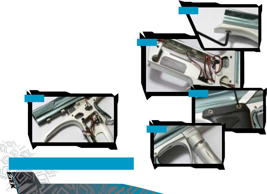
...ASSEMBLING THE ETEK2
Carefully thread the solenoid and Break-Beam Sensor leads through the
access hole in the top of the grip frame (SEE FIGURE 5.51), and reattach the
grip frame to the marker, tightening the grip frame screws using a 1/8”
hex key (SEE FIGURE 5.52).
Ensure that the Break-Beam Sensor cables lie neatly in the slots provided
for them in the Etek2 grip frame. Connect the solenoid and the Break-
Beam Sensors into their relevant places on the Etek2 PCB (SEE FIGURE
5.53). Install a 9volt battery by attaching it to the battery connector and
re-attach the Etek2 grips by securing the six grip screws using a 5/64th"
hex key (SEE FIGURE 5.54).
Screw the inline regulator back into the FRM (SEE FIGURE 5.55) and connect
any hosing that was disconnected. Replace bolt and locate bolt pin in the
designated groove in the rammer.
You have now assembled your Etek2.
NOTE: CHECK THAT NO WIRES ARE TRAPPED BEFORE TIGHTENING
DOWN THE FRAME SCREWS.
FIG 5.51
FIG 5.53
FIG 5.54
FIG 5.52
FIG 5.55
VISIT WWW.PLANETECLIPSE.COM
VISIT WWW.PLANETECLIPSE.COM
35
MAINTENANCE
CLEANING THE BOLT
This procedure can be performed with the Etek2 gassed up as well as
de-gassed.
Raise the bolt pin and remove the bolt and bolt pin from the Etek2 marker
body.
Using a dry Q-tip remove any paint or grease from the surface of the bolt
(SEE FIGURE 5.56).
Replace the bolt, locking the bolt pin into the designated slot in the
rammer.
FIG 5.56
VISIT WWW.PLANETECLIPSE.COM
MAINTENANCE
36
VISIT WWW.PLANETECLIPSE.COM
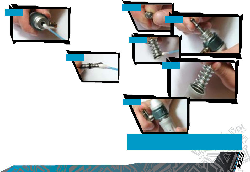
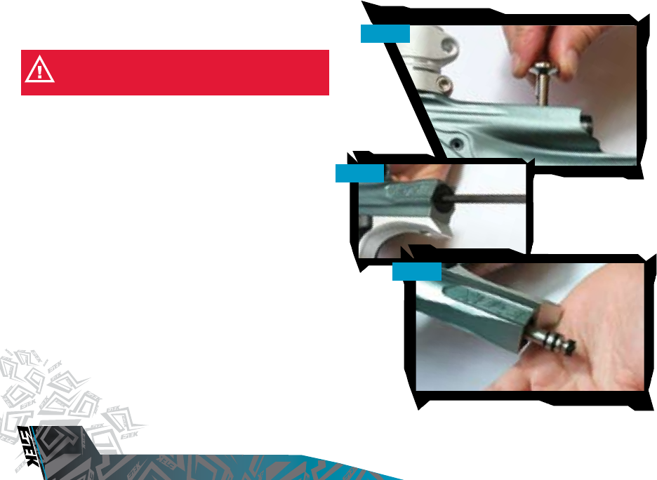
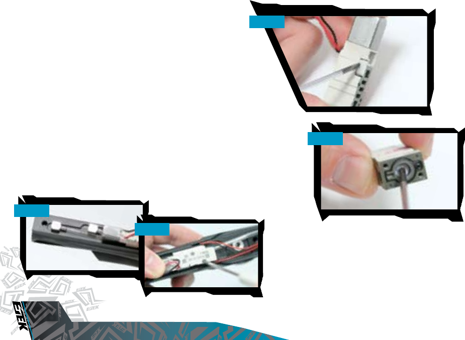
STRIPPING AND CLEANING THE
SOLENOID
Remove the three rubber grip screws from the right hand side of your
grip frame and unplug the solenoid and BBSS from the PCB. Remove
the two frame screws allowing you to remove your frame, Inline regulator
and hosing set-ups from your Etek2 so that you are left with the solenoid
exposed (SEE FIGURE 5.60).
Using a small Philips head screw driver, undo the two solenoid retaining
screws (SEE FIGURE 5.61) and remove the solenoid from the minifold taking
care not to loose the gasket from the face of the minifold.
With the solenoid detached from the minifold, use a small flat instrument
to gently lever the two solenoid retainer clips off the solenoid (SEE FIGURE
5.62). This will allow you to split the solenoid into two and access the
spool valve.
Using a pair of needle-nose pliers remove the spool from the front section
of the solenoid (SEE FIGURE 5.63). Note that it is the flat side of the spool
valve facing you when you remove the spool valve. It may be necessary
to also remove the front cap of the solenoid to push the spool out, if it
cannot be pulled out with the needle nose pliers.
FIG 5.62
FIG 5.60
FIG 5.61
FIG 5.63
VISIT WWW.PLANETECLIPSE.COM
VISIT WWW.PLANETECLIPSE.COM
37
MAINTENANCE
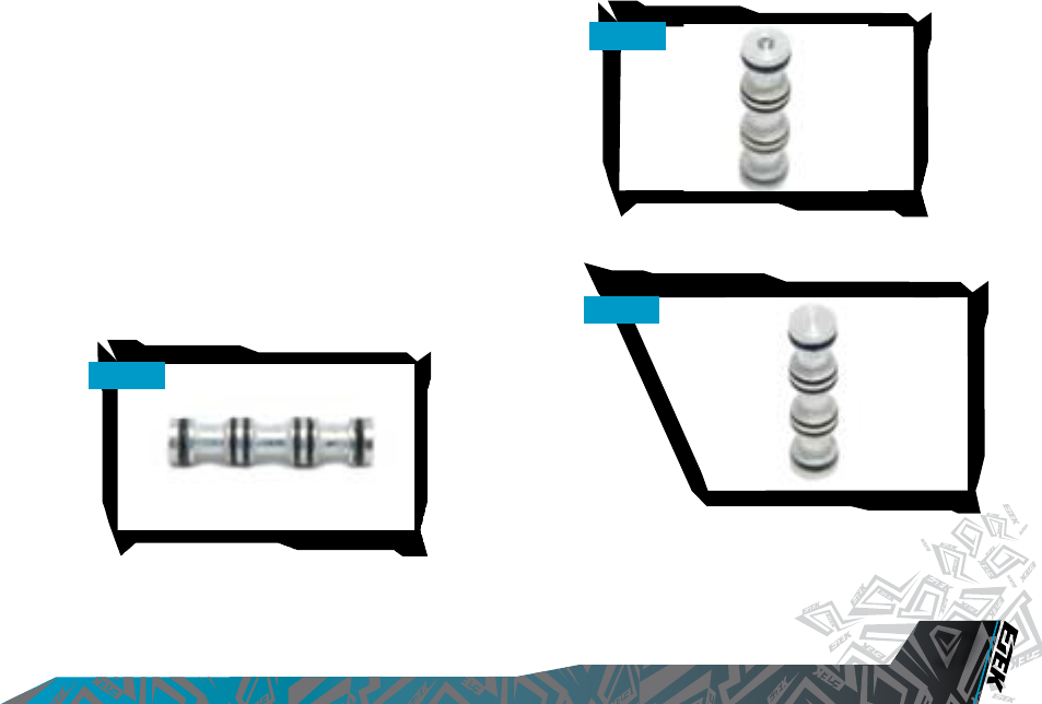
Thoroughly clean and inspect the spool and its O-rings for any debris
or dirt (SEE FIGURE 5.64). Lubricate the o-rings using Dow 33 or similar
lubricant and re-insert the spool into the solenoid body, with the concave
end towards end A of the solenoid body.
FIGURE 5.65 and FIGURE 5.66 show the difference between the flat end of the
spool and the concave end of the spool.
Replace the two solenoid retaining clips to the sides of the solenoid
body and having ensured that the minifold o-rings are in place; screw
the solenoid back into the correct position on the minifold. For reference,
the end of the solenoid with the metal casing should be towards the rear
of the marker.
Replace the Inline regulator, grip frame and hosing set-up, taking care to
feed the solenoid and BBSS leads through the grip frame correctly so that
they do not get caught or damaged. Having screwed in the three rubber
grip screws to finish the process. You have now stripped and cleaned
your Etek2 solenoid.
FIG 5.64
FIG 5.65
FIG 5.66
CONCAVE
FLAT
VISIT WWW.PLANETECLIPSE.COM
FAULT FINDING
38
VISIT WWW.PLANETECLIPSE.COM
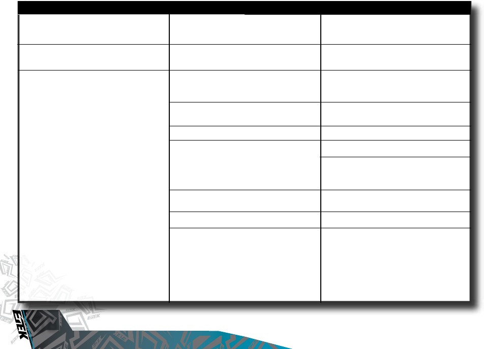
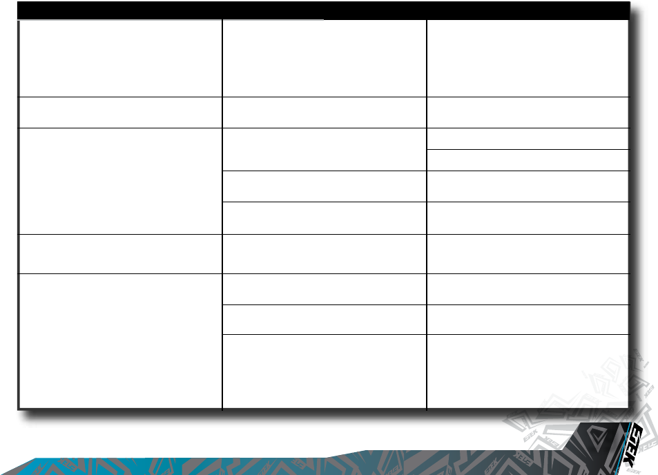
SYMPTOM POSSIBLE CAUSE SOLUTION
Although a fresh battery has been fitted, the
Etek2 will not switch on.
The battery does not seem to last very long.
The Etek2 leaks from the Solenoid
The Battery harness wire is damaged.
The battery type is of a low quality.
Check that gasket is intact and seated
correctly in their designated pockets in the
Minifold.
Dirt on Spool of Etek2 Solenoid.
Damaged Eclipse Etek2 Solenoid.
LPR is supercharging causing intermittent
leaking.
Check for damaged or incorrect seals on
Rammer.
Is it leaking from the Barbs?
14 x 2 O-Rings on LPR Body are damaged
causing over pressurising.
Replace the battery harness or circuit board
as necessary.
Use an alkaline or metal hydride battery. Do
not use a low quality or rechargeable battery.
Replace gasket if damaged using Etek2 Parts
kit. Ensure gasket is seated correctly.
Strip and clean solenoid ( See Maintenance
Section ).
Replace Etek2 Solenoid.
Clean LPR Piston seal.
Inspect regulator seal (in LPR Piston) and
regulator seat (in LPR Body). Replace if
necessary.
Replace seals.
Check hose for cuts or replace minifold.
Replace 14 x 2 O-Rings on LPR Body.
VISIT WWW.PLANETECLIPSE.COM
VISIT WWW.PLANETECLIPSE.COM
39
FAULT FINDING
SYMPTOM POSSIBLE CAUSE SOLUTION
The Etek2 leaks down barrel
Gas vents quickly down barrel as soon as it is
gassed up.
The marker is chopping or trapping paint.
The Etek2 fires yet bolt doesn’t move.
The Etek2 does not fire.
Leaky Exhaust Valve.
Damaged Valve Seat.
Incorrect seal on front of Rammer Housing.
The Exhaust Valve has become jammed in the
brass valve guide.
The Break-Beam Sensor System is switched
off.
The Bolt is dirty, causing the sensor system to
incorrectly detect a retracted bolt.
The Break-Beam Sensor System is dirty
causing the incorrect detection of paintballs.
Bolt pin is not located in Rammer correctly.
Trigger is set up incorrectly.
Solenoid is not plugged into the Etek2 PCB.
The Break-Beam Sensor System is enabled
but there is no paint.
Replace Exhaust Valve.
Replace Rammer Housing.
Replace front seals on Rammer Housing with
016 seals.
Replace Exhaust Valve and brass valve guide
as necessary ( see Maintenance Section ).
Switch on the Break-Beam Sensor System.
Increase the ball detection time.
Clean the Bolt.
Clean the Break-Beam Sensor System.
Lift Bolt pin and line up with position of
rammer correctly ( See Maintenance Section ).
Set trigger up correctly ( See Advanced Set-
Up Section ).
Plug solenoid into port on the Etek2 PCB.
Fill loader with paint / switch off BBSS.

VISIT WWW.PLANETECLIPSE.COM
FAULT FINDING
40
VISIT WWW.PLANETECLIPSE.COM
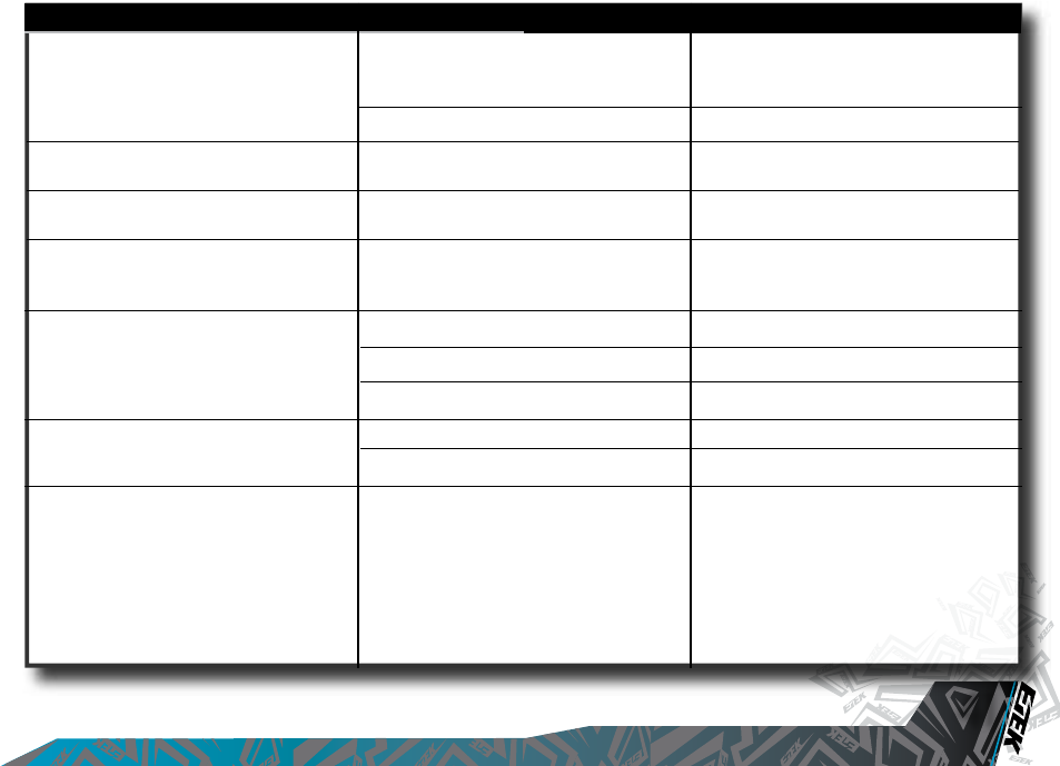
SYMPTOM POSSIBLE CAUSE SOLUTION
Low Velocity First Shot.
High Velocity First Shot.
My Trigger is very “Bouncy”, how can I reduce
it?
The Break-Beam Sensor System does not
appear to be reading correctly.
The Break-Beam Sensor System is not
reading at all.
DWELL parameter is too low to overcome
stiction on Solenoid and / or Rammer O-rings.
DWELL parameter set too high.
Inline Regulator pressure creeping.
Too low Debounce setting.
Lengthen and strengthen your trigger pull.
The Break-Beam Sensor System is dirty.
Break-Beam Sensors are the wrong way
around.
There is a broken wire or contact, or a short
circuit on either of the Breech Sensor ribbon
cables.
Either sensor is back to front.
Increase DWELL parameter.
Reduce DWELL parameter.
Strip and clean Inline Regulator. Replace Inline
Regulator piston if necessary.
Increase Debounce setting.
Refer to Advanced Set-Up Section for
guidelines of how to adjust your Etek2 Trigger
accordingly.
Keep the Break-Beam Sensors clean to
ensure correct readings ( See Maintenance
Section ).
Check that the red receiver is on the right-
hand side of the Breech.
Check the plug of the cables.
Check for cuts or pinches in the sensor
cables.
Check that the sensors face each other when
installed.
VISIT WWW.PLANETECLIPSE.COM
VISIT WWW.PLANETECLIPSE.COM
41
FAULT FINDING
SYMPTOM POSSIBLE CAUSE SOLUTION
Two or more balls are beinng fed into the
breech.
Etek2 is inconsistent.
Leaking Rammer Assembly ( Leak gets louder
when bolt is removed ).
How can I get the best performance out of
my gun?
BBSS turns itself off after firing.
OOPS leaks from front hole (nearest on/off
knob).
OOPS leaks from rear hole (nearest Tank).
If the Etek2 is being used with a force feed
loader, it is possible that the loader is forcing
balls past the ball detent.
Inline Regulator is supercharging.
Front ram shaft seal deteriorated.
Check your set-up.
Eye is dirty.
Eye is faulty.
Eye is out of place.
006 NBR 90 O-Ring too dry.
006 NBR 90 O-Ring damaged.
Tank O-Ring is damaged.
Check that the sensors face each other when
installed.
Change the rubber finger detents.
Strip and clean Inline Regulator ( See
Maintenance Section ).
Replace front Rammer Shaft seal.
Using a force-fed loader ( Halo B, VLocity,
Pulse) with the Break-Beam Sensor System
enabled will give the highest peformance.
Clean the eyes.
Replace the eyes.
Re-Install Eyes. Check alignment.
Lubricate 006 NBR 90 O-Ring with Eclipse Oil.
Replace 006 NBR 90 O-Ring.
Replace the Tank O-Ring.

VISIT WWW.PLANETECLIPSE.COM
SERVICE CENTRES
42
VISIT WWW.PLANETECLIPSE.COM
CERTIFIED ETEK2 SERVICE CENTERS
Are you unsure of where to send your Etek2 to be repaired or serviced? If your local Etek dealer can’t assist you, why not contact your nearest
Certified Etek Service Center and arrange to send it into them to undertake any work that you require.
PLANET ECLIPSE LTD
ENGLAND
Call: +44(0)161 872 5572
Fax: +44(0)161 872 5972
Email: technical@planeteclipse.com
Visit: www.planeteclipse.com
ACTION PAINTBALL GAMES
RUSSIA
Call: +7(0) 95 7851 762
Fax: +7(0) 95 7851 738
Email: info@paintball.ru
Visit: www.paintball.ru
ADRENALICIA S.L.
Spain
Call: ++34 669 011 515
Fax: ++34 986 730 131
Email: jota@adrenalicia.com
Visit: www.adrenalicia.com
TCB PAINTBALL
Sweden
Call: ++46 702 317 361
Email: info@tcbpaintball.com
Visit: www.tcbpaintball.com
COOLGAMES
Finland
Call: ++358 9 586 5312
Email: mikke@ahaa.
Visit: www.coolgames.
OPM
GERMANY
Call: ++49(0) 211 210 2300
Fax: ++49(0) 211 210 23030
Email: salesforce@paintball.de
Visit: www.paintball.de
CAMP
FRANCE
Call: +33(0)1 41 091004
Fax: +33(0)1 41 091009
Email: atelier@paintballcamp.com
Visit: www.paintballcamp.com
PONTO DE MIRA
Portugal
Call: ++351 214 120 144
Fax: ++351 214 120 144
Email: paintball@pontodemira.com
Visit: www.pontodemira.com
WESTSPORT
Norway
Call: ++47 4077 4418
Email: post@westsport.no
Visit: www.westsport.no
BREAKOUT KFT
Hungary
Call: ++36 203 563 604
Email: info@joinpaintball.hu
Visit: www.joinpaintball.hu
ESTRATEGO PORTUGAL
Portugal
Call: ++351 213 863 637
Fax: ++351 213 863 715
Email: info@estratego.pt
Visit: www.estratego.com
SKILL PAINTBALL
Poland
Call: ++48 22 875 2777
Fax: ++48 22 212 8018
Email: info@skill.com.pl
Visit: www.skill.com.pl
AGS
Czech Republic
Call: ++420 272 762 938
Fax: ++420 272 762 938
Email: info@paintballshop.cz
Visit: www.paintballshop.cz
UNITED KINGDOM & EUROPE

VISIT WWW.PLANETECLIPSE.COM
VISIT WWW.PLANETECLIPSE.COM
43
SERVICE CENTRES
PLANET ECLIPSE LLC
Rhode Island
Call: (401) 247 9061
Fax: (401) 247 0931
Email: gerry.b@planeteclipse.com
Visit: www.planeteclipse.com
DGX PAINTBALL
West Coast and
California
Call: (707) 255 5166
Email: Darin@dgxpaintball.com
Visit: www.dgxpaintball.com
PAINTBALL SHOWCASE
East Coast
Call: (401) 353 6040
Email: paintballsupply@aol.com
Visit: www.paintballshowcase.com
GROUND ZERO PAINTBALL
Southern States
Call: (888) 759 2578
Email: egdesigns@hughes.net
Visit: www.gzpaintball.com
EXTREME SKATE AND PAINT
Florida
Call: (305) 248 3145
Email: Mike@espxtremesportz.com
Visit: www.espxtremesportz.com
PRO STAR PAINTBALL
Midwest
Call: (402) 403 1880
Email: Walt@prostarpb.com
Visit: www.prostarpb.com
MAXIMUM PAINTBALL SPORTS
Texas
Call: (210) 659 0424
Email: dy_xfactor@yahoo.com
Visit: www.texasxfactor.com
FOX PAINTBALL
Call: (630) 585 5651
Email: DJ@foxpaintball.com
Visit: www.foxpaintball.com
PAINTBALL CENTRAL
Hawaii
Call: (808) 533 0462
Email: ron@pbchawaii.com
Visit: www.pbchawaii.com
BADLANDS PAINTBALL
Canada
Call: (416) 245 3856
Email: techzone@badlandspaintball.com
Visit: www.badlandspaintball.com
PAINTBALL CENTRAL
North Carolina
Call: (336) 458 0060 (ext. 14)
Fax: (336) 274 5655
Visit: www.paintballcentral.com
www.pbcsportspark.com
SKIRMISH PAINTBALL ASIA
Malaysia
Call: ++603 7722 5629
Fax: ++603 7722 1435
Email: info@skirmishpaintballasia.com
Visit: www.skirmishpaintballasia.com
EXTREME INDOOR PAINTBALL
Australia
Call: ++61 1 300 972468
Email: daniel@extremeindoorpaintball.com.au
Visit: www.extremeindoorpaintball.com.au
ACTION PAINTBALL GAMES
Australia
Call: ++61 2 9679 0011
Fax: ++61 2 9679 0100
Email: sales@actionpaintball.com.au
Visit: www.actionpaintball.com.au
THE PAINTBALL SHOP
South Africa
Call: ++27 413640549
Fax: ++27 413640549
Email: info@paintballshop.co.za
Visit: www.paintballshop.co.za
USA & CANADA
REST OF THE WORLD
VISIT WWW.PLANETECLIPSE.COM
PARTS LIST
44
VISIT WWW.PLANETECLIPSE.COM
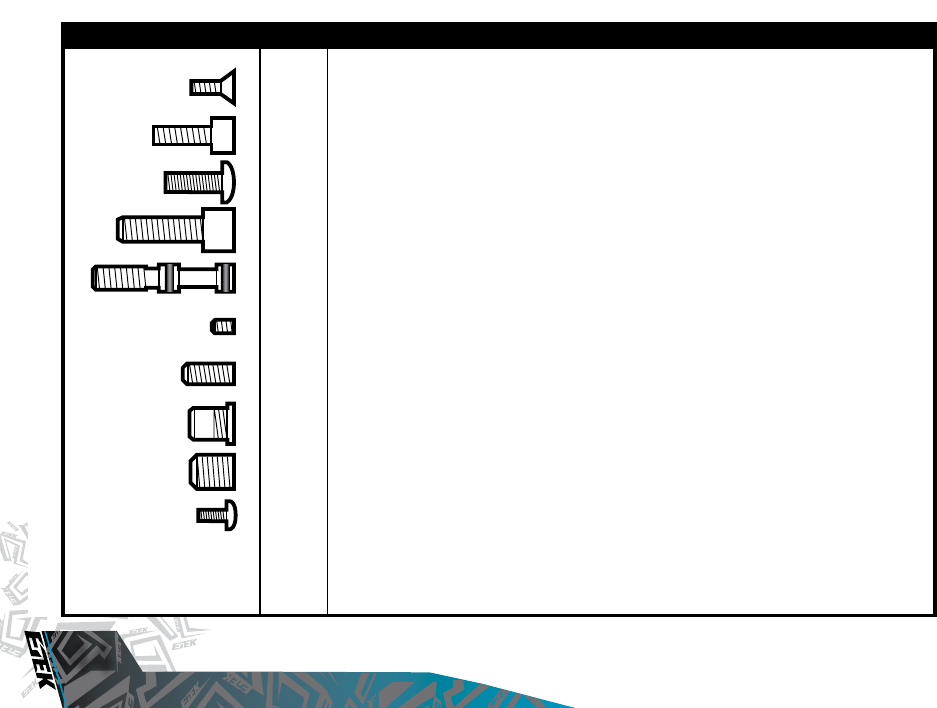
SCREW SIZE CHART
x8 RUBBER GRIP SCREW (6), BBSS COVERS SCREW (2)
(6 - 32 UNC x 3/8 COUNTERSUNK SOCKET)
x2 SHORT FEED NECK SCREW
(10 - 32 UNF x 1/2 CAP HEAD SOCKET)
x2 SHORT FRAME SCREW
(10 - 32 UNF x 3/8 SOCKET BUTTON HEAD)
x1 FRONT REGULATOR MOUNT SCREW
(CUSTOM MANUFACTURED)
x1 INLINE REGULATOR ADJUSTER SCREW
(CUSTOM MANUFACTURED)
x3 TRIGGER ADJUSTMENT SCREW
(6 - 32 UNC x 3/16 SOCKET SET SCREW)
x2 T RAIL SCREW
(10 - 32 UNF x 1/2 SOCKET SET SCREW)
x1 VALVE PLUG
(CUSTOM MANUFACTURED)
x1 LPR ADJUSTER SCREW
(5/16 UNF x 3/8 SOCKET SET SCREW)
SCREW QTY DESCRIPTION
x2 MICRO - SWITCH RETAINER SCREW
(M2 x 10)
VISIT WWW.PLANETECLIPSE.COM
VISIT WWW.PLANETECLIPSE.COM
45
PARTS LIST
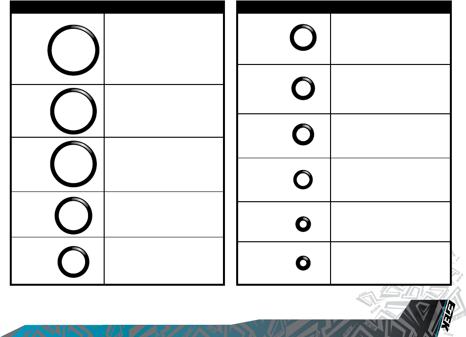
010
009
006
004
Inside LPR body, inside Adjuster
Section of Inline,
Front of OOPS,
LPR Cap.
Rammer Front Bumper,
Rammer Front O-Ring.
Inline Adjuster Screw,
OOPS Insert Front O-Ring.
Small O-Ring on top of Front Reg
Mount.
O-RING LOCATION
Rammer Housing, Feed Stub.
LPR Body*.
Inline Regulator piston,
Front Reg Mount / Body Interface,
Inline Regulator Top.
LPR Piston.
Adjuster Piston.
O-RING LOCATION
016
015
013
012
011
Rear Rammer O-Ring,
Rammer Cap O-Ring.
LPR Body*.
014x2
008
OOPS Insert middle O-Ring.
* = Either 016 or 14 x2 O-Rings can be used on the LPR body due to the fact that it now has three sealing o-rings.
VISIT WWW.PLANETECLIPSE.COM
PARTS LIST
46
VISIT WWW.PLANETECLIPSE.COM
15
16
17
18
19
20
21
23 24
25
26
40
43
47
48
52
51
53
50
54
55
55
56
44
42
39
41
45
46
57
58
61
60
59
62
63 63
35
34
36
64
33
33
33
22
29
37
27
28
31
31
31
38
30
32
05
09
49
01
11
13
12
06
14
02
07
08
04
03
02
10
12
14 14
21
24
31
34
37
46
65
66
66
66
66
67
73 72
70
71
69
68
VISIT WWW.PLANETECLIPSE.COM
VISIT WWW.PLANETECLIPSE.COM
47
PARTS LIST
PART NAME
Valve Guide
Banjo Barb
Rammer Cap
Rammer Cap O-RIng
Valve Plug
Front Rammer O-Ring
Front Rammer Bumper O-Ring
Rear Rammer O-Ring
Exhaust Valve Assembly
Solenoid
Minifold
Minifold Barb
Solenoid Retaining Screw
Low Pressure Hose
LPR Cap
LPR Adjuster Screw
LPR Piston
LPR Piston O-Ring
Adjuster Piston
Adjuster Piston O-Ring
LPR Spring Heavy (Gold)
9 Volt Battery
LPR Body
LPR Body O-Ring
LPR Body Groove O-Ring
FRM Bolt
Frame
Trigger
Printed Circuit Board
Magnet
Trigger Adjuster Screw
Trigger Pin Locking Screw
Push Buttons
PCB Holder
Grip Screw
Navigation Console
Frame Screw
Trigger Pin
Swivel Collar
Inline Regulator Top
Inline Regulator Bottom
Inline Regulator Piston
Inline Regulator Piston O-Ring
Inline Regulator Spring
Inline Regulator Adjuster
Inline Regulator Adjuster O-Ring
Inline Regulator Top O-Ring
Anti-Double Ball Finger
Valve Spring
Bolt
Bolt Pin
Bolt Plunger
Bolt Plunger Spring
Feed Tube
Feed Tube Screw
Body
1/4” Elbow
1/4” Hose
OOPS Body
OOPS Pin
OOPS On/Off Knob
OOPS Insert
OOPS Adjuster Screw
On/Off Button
Rammer Housing
Rammer Housing O-Ring
Rubber Grip
Insert Front O-Ring
Insert Middle O-Ring
Inline Reg Bottom Groove O-Ring
Micro Switch
LPR Cap O-Ring
Rear Rammer Bumper
01
02
03
04
05
06
07
08
09
10
12
11
13
14
15
16
17
18
19
20
21
22
23
24
25
26
27
33
44
50
49
48
47
46
43
45
42
41
40
39
38
37
36
35
32
34
31
30
29
28
63
62
61
60
59
58
57
56
55
54
53
52
51
64
65
66
67
69
68
70
71
72
73
VISIT WWW.PLANETECLIPSE.COM
ACCESSORIES
48
VISIT WWW.PLANETECLIPSE.COM
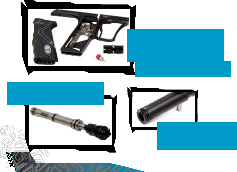
ETEK ZICK KIT.
Zick? What kick? Add the Etek ZICK Kit to your Etek
marker and the existing amount of kick will be reduced
even further. Include a replacement rammer and rammer
cap that must only be used together.
ETEK STAR FRAME KIT
Enhance the performance of your Etek marker by installing
the Etek STAR Frame Kit. Every aspect of the marker to
player interface has been improved from the ball raced
trigger to the cool blue LCD display of the circuit board to
the array of new user - adjustable parameters. We won’t
let your Etek down; why should you?
FEATURES
LCD DISPLAY, DUAL TRIGGER SENSING BOARD, DUAL INSTRUMENT GRADE BALL -
RACED TRIGGER, MAGNETIC TRIGGER RETURN, T - SLOT RAIL MOUNTING SYSTEM AND
ADAPTOR AND FULLY STRIPPABLE ETEK QEV.
CURE BOLT.
Players constantly want to shoot more fragile
paint, yet still run their loaders at the highest
possible speed to maximise their rates of fire.
The Cure bolt for the Ego and the Etek has been
designed to allow you to achieve just that!
VISIT WWW.PLANETECLIPSE.COM
VISIT WWW.PLANETECLIPSE.COM
49
ACCESSORIES
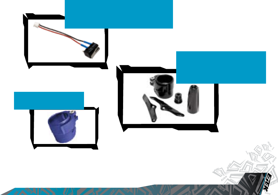
MICRO SWITCH.
Customize the feel of your Etek2 by replacing the micro-
switch inside your Etek2’s trigger frame. This lightened
micro-switch will make the trigger feel more responsive
as well as upping your potential rate of fire.
EGO CCU KITS
CONTRAST COLOUR UPGRADE KITS.
This unique kit allows you to swap and
customize the look of your Etek marker by
replacing these key components. Available in
various colours.
CLEVER FEED.
Makes fitting your loader a breeze.
Available in various colours.
VISIT WWW.PLANETECLIPSE.COM
ACCESSORIES
50
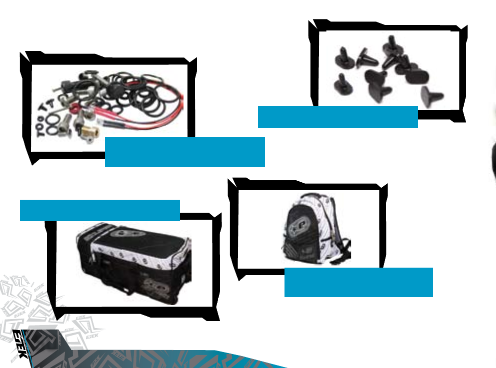
COMPREHENSIVE SPARES KIT.
Kit features a combination of all the required
spares for the Etek2.
DETENT KIT.
10 Replacement rubber Detents for your Etek2.
08 STRIPE KITBAG.
What better place to keep your Etek2?
08 STRIPE LAPTOP BAG
Transport your Laptop in style with the new ‘08
Laptop Bag.
VISIT WWW.PLANETECLIPSE.COM

OPERATORS MANUAL
Etek, the Etek Icon, Ego and the Ego logo are all trademarks of Planet Eclipse Ltd. All artwork and texts © Copyright 2007. ETEGM08V2
