Planet Technology Fgsw 1828Ps Users Manual For FNSW 1608PS /
31744-Installationsheet 31744-InstallationSheet 31744-InstallationSheet 004169 Batch12 unilog cesco-content
FGSW-1828PS EM_FN1608v2_FG1828_v1.0
FNSW-1608PS to the manual 1d0d7f39-66ec-479b-b87b-f3d99d195e70
2015-02-06
: Planet-Technology Planet-Technology-Fgsw-1828Ps-Users-Manual-519206 planet-technology-fgsw-1828ps-users-manual-519206 planet-technology pdf
Open the PDF directly: View PDF ![]() .
.
Page Count: 72
- Revision
- 1. INTRODUCTION
- 2. HARDWARE DESCRIPTION
- 3. SWITCH MANAGEMENT
- 4. WEB MANAGEMENT
- 5. SWITCH OPERATION
- 6. POWER OVER ETHERNET OVERVIEW
- 7. THE POE PROVISION PROCESS
- 8. TROUBLESHOOTING
- APPENDIX A NETWORKING CONNECTION
- EC Declaration of Conformity

User's Manual
FNSW-1608PS
FGSW-1828PS
16-Port 10/100Mbps
Web Smart PoE Switch
- 1 -

- 2 -
Trademarks
Copyright © PLANET Technology Corp. 2008.
Contents subject to revision without prior notice.
PLANET is a registered trademark of PLANET Technology Corp. All other trademarks belong to their respective
owners.
Disclaimer
PLANET Technology does not warrant that the hardware will work properly in all environments and applications,
and makes no warranty and representation, either implied or expressed, with respect to the quality, performance,
merchantability, or fitness for a particular purpose.
PLANET has made every effort to ensure that this User’s Manual is accurate; PLANET disclaims liability for any
inaccuracies or omissions that may have occurred.
Information in this User’s Manual is subject to change without notice and does not represent a commitment on the
part of PLANET. PLANET assumes no responsibility for any inaccuracies that may be contained in this User’s
Manual. PLANET makes no commitment to update or keep current the information in this User’s Manual, and
reserves the right to make improvements to this User’s Manual and/or to the products described in this User’s
Manual, at any time without notice.
If you find information in this manual that is incorrect, misleading, or incomplete, we would appreciate your
comments and suggestions.
FCC Warning
This equipment has been tested and found to comply with the limits for a Class A digital device, pursuant to Part
15 of the FCC Rules. These limits are designed to provide reasonable protection against harmful interference
when the equipment is operated in a commercial environment. This equipment generates, uses, and can radiate
radio frequency energy and, if not installed and used in accordance with the Instruction manual, may cause
harmful interference to radio communications. Operation of this equipment in a residential area is likely to cause
harmful interference in which case the user will be required to correct the interference at his own expense.
CE Mark Warning
This is a Class A product. In a domestic environment, this product may cause radio interference, in which case the
user may be required to take adequate measures.
WEEE Warning
To avoid the potential effects on the environment and human health as a result of the presence of
hazardous substances in electrical and electronic equipment, end users of electrical and electronic
equipment should understand the meaning of the crossed-out wheeled bin symbol. Do not dispose of
WEEE as unsorted municipal waste and have to collect such WEEE separately.
Revision
PLANET 16-Port 10/100Mbps Web Smart PoE Switch User's Manual
FOR MODELS: FNSW-1608PS / FGSW-1828PS
REVISION: FNSW-1608PSv2 / FGSW-1828PS (June.2008)
Part No.: 2080-A31120-006

- 3 -
TABLE OF CONTENTS
1. INTRODUCTION............................................................................................................5
1.1 CHECKLIST ................................................................................................................................................ 5
1.2 ABOUT THE SWITCH ................................................................................................................................... 5
1.3 FEATURES ................................................................................................................................................. 6
1.4 SPECIFICATION .......................................................................................................................................... 6
2. HARDWARE DESCRIPTION ........................................................................................8
2.1 FRONT PANEL ............................................................................................................................................ 8
2.2 REAR PANEL.............................................................................................................................................. 9
2.3 HARDWARE INSTALLATION .......................................................................................................................... 9
3. SWITCH MANAGEMENT............................................................................................11
3.1 OVERVIEW ............................................................................................................................................... 11
3.2 MANAGEMENT METHOD............................................................................................................................ 11
3.2.1 Web Management........................................................................................................................... 11
3.2.2 PLANET Smart Discovery Utility..................................................................................................... 12
3.3 LOGGING ON TO THE FNSW-1608PS / FGSW-1828PS ........................................................................... 13
4. WEB MANAGEMENT...................................................................................................14
4.1 LOGIN IN TO THE SWITCH .......................................................................................................................... 14
4-2 SYSTEM................................................................................................................................................... 16
4.2.1 System Information ......................................................................................................................... 17
4.2.2 IP Configuration .............................................................................................................................. 18
4.2.3 Password Setting ............................................................................................................................ 19
4.2.4 Alert Trap ........................................................................................................................................ 20
4.2.5 Factory Default................................................................................................................................21
4.2.6 Firmware Update ............................................................................................................................ 22
4.2.7 Reboot............................................................................................................................................. 25
4-3 PORT MANAGEMENT ................................................................................................................................26
4.3.1 Port Configuration ........................................................................................................................... 27
4.3.2 Port Mirroring .................................................................................................................................. 29
4.3.3 Bandwidth Control........................................................................................................................... 30
4.3.4 Broadcast Storm Control................................................................................................................. 31
4.3.5 Port Statistics .................................................................................................................................. 32
4-4 VLAN SETTING........................................................................................................................................ 33
4.4.1 802.1Q VLAN.................................................................................................................................. 36
4.4.2 Port Based VLAN............................................................................................................................ 45
4.4.3 MTU VLAN ...................................................................................................................................... 47
4-5 TRUNK SETTING....................................................................................................................................... 48
4-6 QOS SETTING.......................................................................................................................................... 50
4.6.1 Priority Mode................................................................................................................................... 51
4.6.2 Class of Service Configuration ....................................................................................................... 52
4.6.3 TCP / UDP Port Based QoS ........................................................................................................... 53
4-7 SECURITY FILTER..................................................................................................................................... 55
4.7.1 MAC Address Filter......................................................................................................................... 56
4.7.2 TCP / UDP Filter ............................................................................................................................. 57
4-8 MISC OPERATION..................................................................................................................................... 59
4-9 POE SETTING ......................................................................................................................................... 60
4-10 LOGOUT ................................................................................................................................................ 62
5. SWITCH OPERATION..................................................................................................63
5.1 ADDRESS TABLE ...................................................................................................................................... 63
5.2 LEARNING ................................................................................................................................................ 63
5.3 FORWARDING & FILTERING ....................................................................................................................... 63
5.4 STORE-AND-FORWARD............................................................................................................................. 63

- 4 -
5.5 AUTO-NEGOTIATION ................................................................................................................................. 63
6. POWER OVER ETHERNET OVERVIEW.....................................................................64
7. THE POE PROVISION PROCESS...............................................................................66
7.1 LINE DETECTION ...................................................................................................................................... 66
7.2 CLASSIFICATION....................................................................................................................................... 66
7.3 START-UP ................................................................................................................................................ 67
7.4 OPERATION.............................................................................................................................................. 67
7.5 POWER DISCONNECTION SCENARIOS ........................................................................................................ 67
8. TROUBLESHOOTING..................................................................................................68
APPENDIX A NETWORKING CONNECTION .................................................................69
A.1 SWITCH‘S RJ-45 PIN ASSIGNMENTS ......................................................................................................... 69
A.2 RJ-45 CABLE PIN ASSIGNMENT ................................................................................................................. 69

- 5 -
1. INTRODUCTION
1.1 Checklist
Check the contents of your package for following parts:
z FNSW-1608PS or FGSW-1828PS x1
z Quick Installation Guide x1
z User's manual CD x1
z Power cord x 1
z Rubber feet x 4
z Two rack-mounting brackets with attachment screws x1
If any of these pieces are missing or damaged, please contact your dealer immediately, if possible, retain the carton
including the original packing material, and use them against to repack the product in case there is a need to return it to
us for repair.
In the following section, the term “Web Smart PoE Switch” means the two Switch devices, ie. FNSW-1608PS and
FGSW-1828PS; term of “switch” can be any third switches.
1.2 About the Switch
The Web Smart PoE Switch provide 16 10/100Mbps Fast Ethernet ports with 8 PoE interfaces, the Web Smart PoE Switch
supports MDI / MDI-X convertible on 16-10/100Mbps ports and also provide PoE inject function on port#1 to port#8 which
is able to drive 8 IEEE 802.3af compliant powered devices.
The unshielded twisted-pair (UTP) cable ports providing dedicated 10/100Mbps bandwidth, the dual speed ports used
standard twisted-pair cabling and are ideal for SOHO or segmenting networks into small. Each 10/100Mbps port can
supports up to 200Mbps of throughput in full-duplex mode, the Web Smart PoE Switch also provides a simple,
cost-effective, and highly reliable network connection for data as well as power. Furthermore, it is the ideal device for
bridging among Ethernet, Fast Ethernet workgroups and networks.
The Web Smart PoE Switch equipped with non-blocking 3.2 / 7.2Gbps backplane, greatly simplifies the tasks of upgrading
your LAN for catering to increase bandwidth demands.
For efficient management, the Web Smart PoE Switch is equipped with remote Web interface. The Web Smart PoE Switch
can be programmed for advanced switch management functions such as SNMP Alert Trap, port configuration, port-based
/ IEEE 802.1Q / MTU VLAN, port mirroring, port trunk, QoS, bandwidth control, broadcast storm control, MAC address /
TCP & UDP filter and IGMP Snooping v1/v2. Also the PoE Setting, such as PoE power Disable/Enable and PoE power
consumption monitoring
The FGSW-1828PS also provide two Gigabit Ethernet ports, either TP or SFP per port. The two Gigabit ports either can be
1000Base-T for 10/100/1000Mbps or 1000Base-SX/LX through SFP (Small Factor Pluggable) interfaces. The distance
can be extended from 100 meters (TP), 550 meters (Multi-mode fiber), up to above 10/20/30/40/50/70/120 kilometers
(Single-mode fiber).
With its Auto-Negotiation capability, all the RJ-45/STP ports of Web Smart PoE Switch can be configured to speeds of
10/20Mbps / 100/200Mbps (Fast Ethernet) or1000/2000Mbps (Gigabit Ethernet) automatically. In addition, the products
are equipped with the MDI/MDI-X auto detection for easily plug and play connection, regardless of cabling types-straight
through or crossover.

- 6 -
1.3 Features
◆ Complies with the IEEE 802.3, IEEE 802.3u, IEEE 802.3ab, IEEE 802.3z Gigabit Ethernet standard
◆ 16-Port 10/100Mbps with 8-Port PoE Web Smart PoE Switch (FNSW-1608PS)
◆ 16-Port 10/100Mbps + 2 Gigabit TP / SFP Combo Web Smart PoE Switch (FGSW-1828PS)
◆ 8-Port support 48VDC power to PoE Powered Device (Port 1 to port 8)
◆ Each Switching ports support auto-negotiation-10/20, 100/200Mbps (Fast Ethernet) , 1000/2000Mbps (Gigabit
Ethernet) supported
◆ Auto-MDI/MDI-X detection on each RJ-45 port
◆ Prevents packet loss with back pressure (Half-duplex) and IEEE 802.3x PAUSE frame flow control (Full-duplex)
◆ High performance Store and Forward architecture, broadcast storm control, runt/CRC filtering eliminates erroneous
packets to optimize the network bandwidth
◆ 4K MAC address table, automatic source address learning and ageing
◆ 2.75Mb embedded memory for packet buffers
◆ Remote Web interface for Switch management and setup
◆ SNMP Trap for alarm notification of events
◆ Broadcast Storm Control support
◆ Supports up to 16 / 18 port-based VLAN groups / 32 IEEE 802.1Q VLAN groups / MTU VLAN
◆ Supports up to 2 Trunk groups, each trunk for up to maximum 4 port with 800Mbps bandwidth
◆ Supports QoS , bandwidth control and MAC address filter / TCP & UDP filter on each port
◆ Supports port mirroring function and IGMP Snooping v1 / v2
◆ PoE power Disable/Enable and PoE power consumption monitoring by management interface
◆ Firmware upgrade through Web interface
◆ Password setting, IP setting and device description setting through Planet Smart discovery utility
◆ 19-inch rack mount size
◆ Internal full-range power supply suitable for worldwide use
◆ EMI standards complies with FCC, CE class A
1.4 Specification
Model FNSW-1608PS FGSW-1828PS
Hardware Specification
Fast Ethernet Ports 16 10/ 100Base-TX RJ-45 Auto-MDI/MDI-X ports
Gigabit ports None 2 Gigabit TP / SFP combo interfaces
Power over Ethernet ports 8-Port with PoE injector function (Port 1 to port 8)
Switch Processing Scheme Store-and-Forward
Throughput (packet per sec-
ond) 2.38Mpps. 5.35Mpps.
Switch fabric 3.2Gbps. 7.2Gbps
Address Table 4K entries
Share data Buffer 2.75Mb embedded memory for packet buffers
Flow Control Back pressure for half duplex, IEEE 802.3x Pause Frame for full duplex

- 7 -
Dimensions 440 x 120 x 44 mm (1U height)
Weight 1.75 kg 2.02 kg
Power Requirement 100-240V AC, 50-60 Hz, 1A
System operation Power Con-
sumption / Dissipation (Full
load)
13.5 watts / 46BTU 21 watts / 71BTU
Temperature Operating: 0~50 degree C
Storage: -40~70 degree
Humidity Operating: 5% to 90%, Storage: 5% to 90% (Non-condensing)
Power over Ethernet
PoE Standard IEEE 802.3af Power over Ethernet / PSE
PoE Power Supply Type End-Span
PoE Power Output Per Port 48V DC, 350mA . Max. 15.4 watts
Power Pin Assignment 1/2(+), 3/6(-)
Power Budget 110 watts
Smart function
System Configuration Web interface
Alert Trap SNMP Trap for alarm notification of events
Port configuration Port speed duplex mode selection. Flow control disable / enable. Port disable /
enable. Port description on each port
Bandwidth Control Yes, 1Mbps / 2Mbps / 4Mbps / 8Mbps / 16Mbps / 32Mbps / 64Mbps
Broadcast Storm Control Yes, 5% / 10% / 25% / 50% / Disable
Port Statistics Display each port’s detail Ethernet traffic counter information
VLAN 16 / 18 port-based VLAN groups / 32 IEEE 802.1Q VLAN groups / MTU VLAN
Port trunking Support 2 groups of 4-Port trunk support, up to 800Mbps bandwidth per trunk
Port Mirroring Port mirroring allows monitoring of the traffic across any port in real time
QoS Allow to assign low / high priority on each port.
First-In-First-Out, All-High-before-Low, Weight-Round-Robin QoS policy.
MAC address / TCP & UDP filter Yes
IGMP Snooping v1 / v2 Allow to disable or enable.
PoE power control Allow to disable or enable power provision and assign priority on each PoE port
Standards Conformance
Regulation Compliance FCC Part 15 Class A, CE
Standards Compliance
IEEE 802.3 Ethernet
IEEE 802.3u Fast Ethernet
IEEE 802.3ab Gigabit Ethernet
IEEE 802.3z Gigabit Ethernet
IEEE 802.3x Full-duplex Flow control
IEEE 802.3af Power over Ethernet
IEEE 802.1Q VLAN
IEEE 802.1p QoS
- 8 -
2. HARDWARE DESCRIPTION
This product provides three different running speeds – 10Mbps, 100Mbps and 1000Mbps in the same Web Smart PoE
Switch and automatically distinguishes the speed of incoming connection.
This section describes the hardware features of Web Smart PoE Switch. For easier management and control of the Web
Smart PoE Switch, familiarize yourself with its display indicators, and ports. Front panel illustrations in this chapter display
the unit LED indicators. Before connecting any network device to the Web Smart PoE Switch, read this chapter carefully.
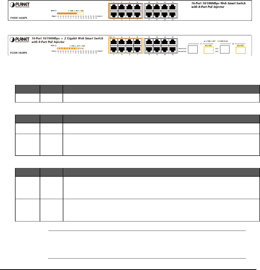
2.1 Front Panel
The Front Panel of the Web Smart PoE Switch consists of 16 Auto-Sensing 10/100Mbps Ethernet RJ-45 Ports, Also the
FGSW-1828PS provides 2 Gigabit TP/SFP combo ports either can be 1000Base-T for 10/100/1000Mbps or
1000Base-SX/LX through SFP (Small Factor Pluggable) interface.
The LED Indicators are also located on the front panel of the Web Smart PoE Switch.
Po E
Po E I n U se
Figure 2-1: FNSW-1608PS Switch front panel
Figure 2-2: FGSW-1828PS Switch front panel
2.1.1 LED indicators
System
LED Color Function
PWR Green Lights to indicate that the Switch has power.
Per 10/100Mbps port
LED Color Function
PoE In-use Orange Lights to indicate the port is providing 48VDC in-line power. (1-8 ports)
LNK/ACT Green Lights to indicate the link through that port is established at 10/100Mbps full duplex mode.
Blink slowly to indicate the link through that port is established at 10/100Mbps half duplex mode.
Blink fast to indicate that the Switch is actively sending or receiving data over that port.
Per 10/100/1000Base-T port / SFP interfaces (FGSW-1828PS only)
LED Color Function
LNK/ACT Green
Lights to indicate the link through that port is established at 10/100/1000Mbps full duplex mode.
Blink slowly to indicate the link through that port is established at 10/100Mbps half duplex mode.
Blink fast to indicate that the Switch is actively sending or receiving data over that port.
100/1000 Green
Steady Lights to indicate the port is run at 1000Mbps.
Blink Slowly to indicate the port is run at 100Mbps
Off: indicate that the port is operating at 10Mbps.
#Notice: 1.Press the RESET button once. The Web Smart PoE Switch will reboot automatically.
2. Press the RESET button for 5 seconds. The Web Smart PoE Switch will back to the factory
default mode; the entire configuration will be erased.

- 9 -
2.2 Rear Panel
The rear panel of the Web Smart PoE Switch indicates an AC inlet power socket, which accepts input power from 100 to
240VAC, 50-60Hz, 1A.
100~240V AC
50 / 60Hz
Figure 2-3: FNSW-1608PS / FGSW-1828PS Switch rear panel
Power Notice:
1. The device is a power-required device, it means, it will not work till it is powered. If your networks should active all the
time, please consider using UPS (Uninterrupted Power Supply) for your device. It will prevent you from network data
loss or network downtime.
2. In some area, installing a surge suppression device may also help to protect your Web Smart PoE Switch from being
damaged by unregulated surge or current to Web Smart PoE Switch.
2.3 Hardware Installation
This part describes how to install your Web Smart PoE Switch and make connections to the Switch. Please read the fol-
lowing topics and perform the procedures in the order being presented. To install your Web Smart PoE Switch on a desktop
or shelf, simply completed the following steps.
2.3.1 Desktop Installation
To install Web Smart PoE Switch on a desktop or shelf, simply completed the following steps:
Step 1: Attached the rubber feet to the recessed areas on the bottom of the Web Smart PoE Switch.
Step 2: Place the Web Smart PoE Switch on a desktop or shelf near an AC power source.
Step 3: Keep enough ventilation space between the Web Smart PoE Switch and the surrounding objects.
#Notice:
When choosing a location, please keep in mind the environmental restrictions discussed in
Chapter 1, Section 4, Specification.
Step 4: Connect your Switch to network devices.
A. Connect one end of a standard network cable to the 10/100 RJ-45 ports on the front of the Web Smart PoE Switch.
B. Connect the other end of the cable to the network devices such as printer servers, workstations or routers…etc.
#Notice:
Connection to the Web Smart PoE Switch requires UTP Category 5 network cabling with RJ-45
tips. For more information, please see the Cabling Specification in Appendix A.
Step 5: Supply power to the Web Smart PoE Switch.
A. Connect one end of the power cable to the Web Smart PoE Switch.
B. Connect the power plug of the power cable to a standard wall outlet then power on the Web Smart PoE Switch.
When the Web Smart PoE Switch receives power, the Power LED should remain solid Green.
- 10 -
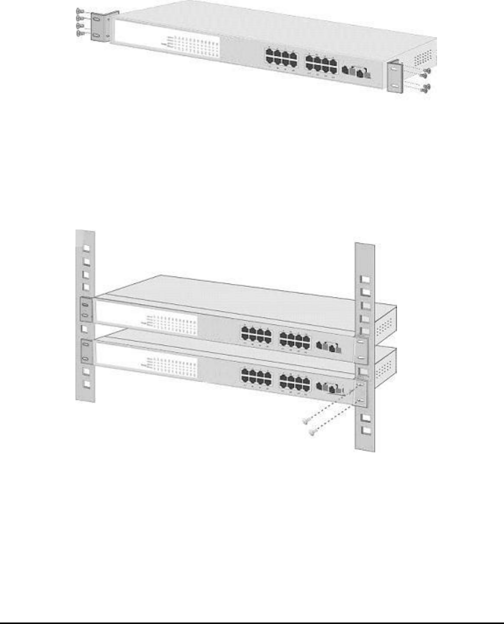
2.3.2 Rack Mounting
To install the Web Smart PoE Switch in a 19-inch standard rack, follow the instructions described below.
Step 1: Place your Web Smart PoE Switch on a hard flat surface, with the front panel positioned towards your front side.
Step 2: Attach a rack-mount bracket to each side of the Web Smart PoE Switch with supplied screws attached to the
package. Figure 2-4 shows how to attach brackets to one side of the Web Smart PoE Switch.
Figure 2-4 Attaching the brackets to the Web Smart PoE Switch
Caution:
You must use the screws supplied with the mounting brackets. Damage caused to the parts by using incorrect screws
would invalidate your warranty.
Step 3: Secure the brackets tightly.
Step 4: Follow the same steps to attach the second bracket to the opposite side.
Step 5: After the brackets are attached to the Web Smart PoE Switch, use suitable screws to securely attach the brackets
to the rack, as shown in Figure 2-5.
Figure 2-5 Mounting the Web Smart PoE Switch in a Rack
Step 6: Proceed with the steps 4 and steps 5 of section 2.3.1 Desktop Installation to connect the network cabling and
supply power to your Web Smart PoE Switch.
- 11 -
3. SWITCH MANAGEMENT
This chapter describes how to manage the Web Smart PoE Switch. Topics include:
- Overview
- Management method
- Logging on to the Web Smart PoE Switch
3.1 Overview
The Web Smart PoE Switch provides a user-friendly, Web interface. Using this interface, you can perform various switch
configuration and management activities, including:
Please refer to the following Chapter 4 for the details.
3.2 Management Method
User can manage the Web Smart PoE Switch by Web Management via a network connection.
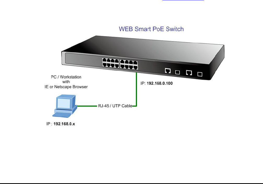
3.2.1 Web Management
The PLANET Web Smart PoE Switch provide a built-in browser interface. You can manage the Switch remotely by having
a remote host with Web browser, such as Microsoft Internet Explorer, Netscape Navigator or Mozilla Firefox.
The following shows how to startup the Web Management of the Switch, please note the Web Smart PoE Switch is con-
figured through an Ethernet connection, make sure the manager PC must be set on the same IP subnet address, for
example, the default IP address of the Switch is 192.168.0.100 (the factory-default IP address), then the manager PC
should be set at 192.168.0.x (where x is a number between 1 and 254, except 100), and the default subnet mask is
255.255.255.0.
Use Internet Explorer 5.0 or above Web browser, enter default IP address http://192.168.0.100
After entering the username and password (default user name and password is “admin”) in login screen
- 12 -
3.2.2 PLANET Smart Discovery Utility
You can manage the Web Smart PoE Switch remotely by having a remote host with Web browser, such as Microsoft
Internet Explorer or Netscape Navigator.
Using this management method:
The Web Smart PoE Switch must have an Internet Protocol (IP) address accessible for the remote host. For easily list the
FNSW-1608PS / FGSW-1828PS in your Ethernet environment, the Planet Smart Discovery Utility from user’s manual
CD-ROM is an ideal solution.
The following install instructions guiding you for run the Planet Smart Discovery Utility.
1. Deposit the Planet Smart Discovery Utility in administrator PC.
2. Run this utility and the following screen appears.
Figure 3-1 Planet Smart Discovery Utility Screen
#Notice: If there are two LAN cards or above in the same administrator PC, choose different LAN card by
use the “Select Adapter” tool.
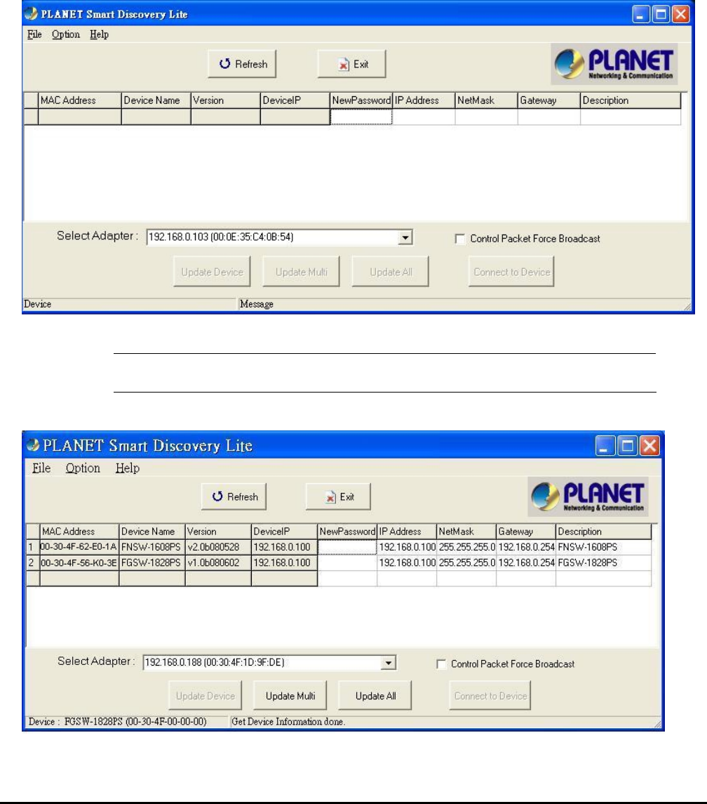
3. Press “Refresh” button for list current connected devices in the discovery list, the screen is shown as follow.
Figure 3-2 Planet Smart Discovery Utility Screen
- 13 -
4. This utility show all necessary information from the devices, such as MAC Address, Device Name, firmware version,
Device IP Subnet address, also can assign new password, IP Subnet address and description for the devices.
5. After setup completed, press “Update Device”, “Update Multi” or “Update All” button to take affect. The meaning of
the 3 buttons above are shown as below:
Update Device: use current setting on one single device.
Update Multi: use current setting on choose multi-devices.
Update All: use current setting on whole devices in the list.
The same functions mentioned above also can be finding in “Option” tools bar.
6. To click the “Control Packet Force Broadcast” function, it can allow assign new setting value to the Web Smart PoE
Switch under different IP subnet address.
7. Press “Connect to Device” button then the Web login screen appears in Figure 3-3.
8. Press “Exit” button to shutdown the planet Smart Discovery Utility.
3.3 Logging on to the FNSW-1608PS / FGSW-1828PS
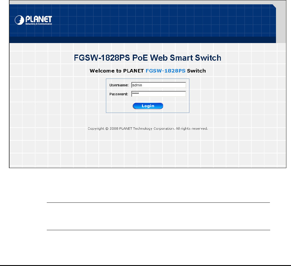
When you log on to the Web Smart PoE Switch Web interface for the first time, a sign-on string appears and you are
prompted for a Web login username and password.
Figure 3-3 Web Smart PoE Switch Web Login Screen
The factory default login username and password is admin.
#Notice: 1. For FNSW-1608PS the display will be the same to FGSW-1828PS.
2. For security reason, please change and memorize the new password after this first
setup.
- 14 -
4. WEB MANAGEMENT
To modify your PC’s IP domain to the same with Web Smart PoE Switch then use the default IP address (192.168.0.100)
to remote configure Web Smart PoE Switch through the Web interface.
#Notice: The following section will base on the console screens of FGSW-1828PS, for FNSW-1608PS the
display will be the same to FGSW-1828PS.
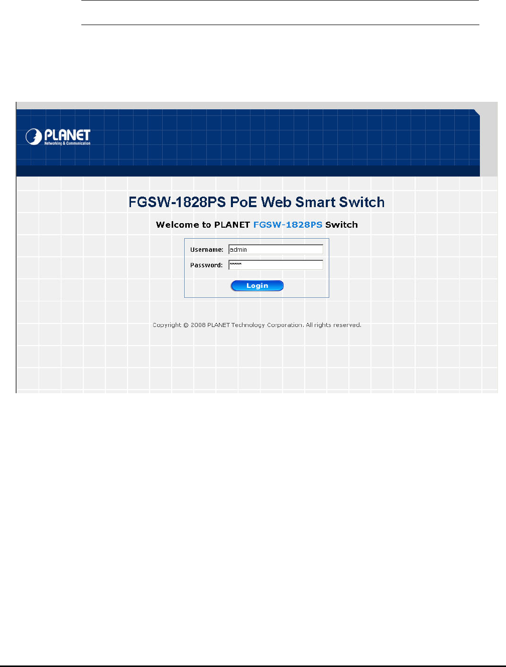
4.1 Login in to the Switch
To access the Web-browser interface you must first enter the user name and password, the default user name and
password is "admin”. You will see the following screen comes out on the Web browser program:
Figure 4-1 Web Login Screen
After the User name and Password is entered, you will see the Web Main Menu screen.
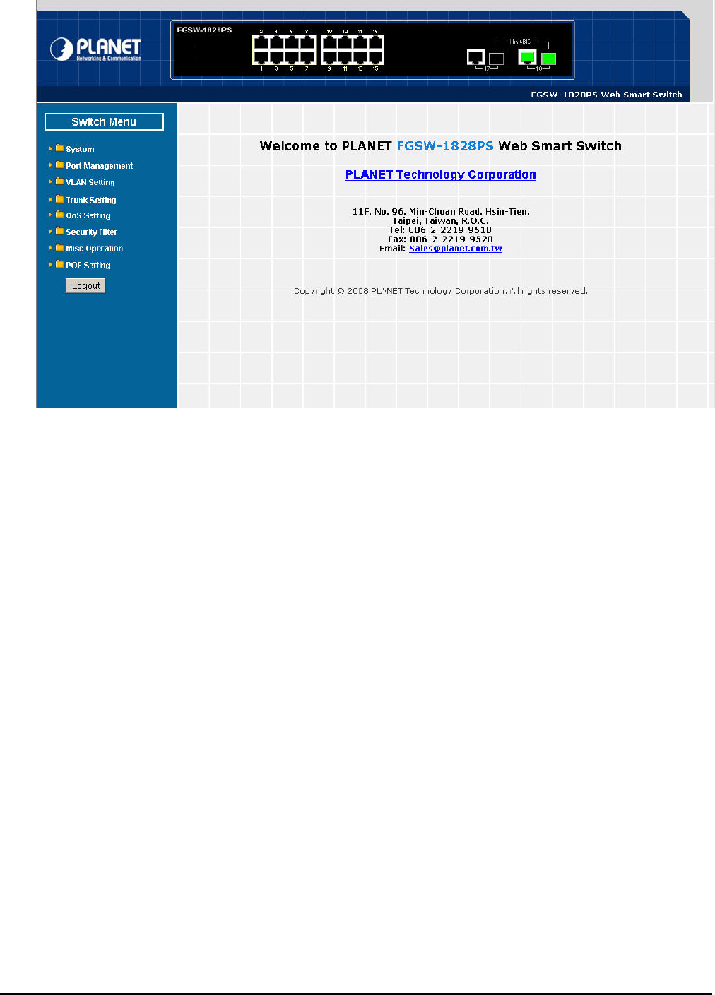
- 15 -
The Switch Menu provide eight major management functions, the screen in Figure 4-2 appears.
Figure 4-2 Web Main Menu Screen
These items and its description shown as below:
◆ System: Provide System configuration of Web Smart PoE Switch. Explained in section 4.2.
◆ Port Management: Provide Port Management configuration of Web Smart PoE Switch. Explained in section 4.3.
◆ VLAN Setting: Provide VLAN Setting configuration of Web Smart PoE Switch. Explained in section 4.4.
◆ Trunk Setting: Provide Trunk Setting configuration Web Smart PoE Switch. Explained in section 4.5.
◆ QoS Setting: Provide QoS Setting configuration of Web Smart PoE Switch. Explained in section 4.6.
◆ Security: Provide Security configuration of Web Smart PoE Switch. Explained in section 4.7.
◆ Misc Operation: Provide Misc Operation configuration of Web Smart PoE Switch. Explained in section 4.8.
◆ POE Setting: Provide POE Setting configuration of Web Smart PoE Switch. Explained in section 4.9.
◆ Logout: Provide Logout function of Web Web Smart PoE Switch. Explained in section 4.10.
- 16 -
4-2 System
This section provides System Information, IP Configuration, Password Setting, Alert Trap, Factory Default, Firmware
Update and Reboot functions of Web Smart PoE Switch, the screen in Figure 4-3 appears and table 4-1 describes the
System object of Web Smart PoE Switch.
Figure 4-3 System Web Page Screen
Table 4-1 Descriptions of the System Web Page Screen Objects
Object Description
System Information Display the MAC address, Hardware Version, and Software Version, Device Description. Ex-
plained in section 4.2.1.
IP Configuration Allow to change the IP subnet address of Web Smart PoE Switch. Explained in section 4.2.2.
Password Setting Allow to change the username and password of Web Smart PoE Switch. Explained in section
4.2.3.
Alert Trap Allow configure the Alert Trap function of Web Smart PoE Switch. Explained in section 4.2.4.
Factory Default Allow reset the Web Smart PoE Switch to factory default mode. Explained in section 4.2.5.
Firmware Update
A
llow proceed firmware upgrade process of Web Smart PoE Switch. Explained in section
4.2.6.
Reboot Allow reboot the Web Smart PoE Switch. Explained in section 4.2.7.
- 17 -
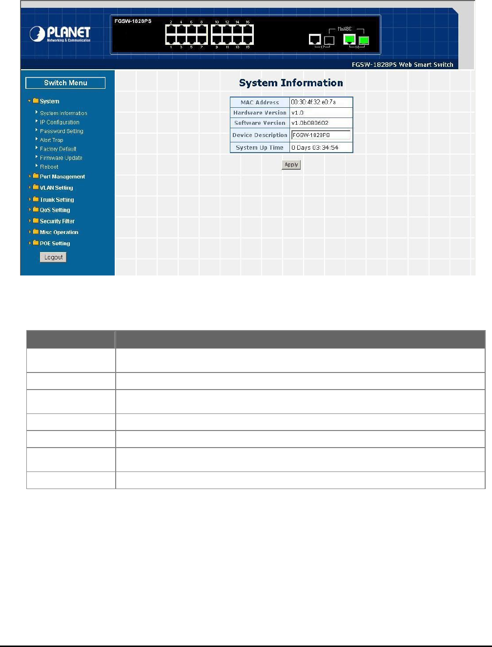
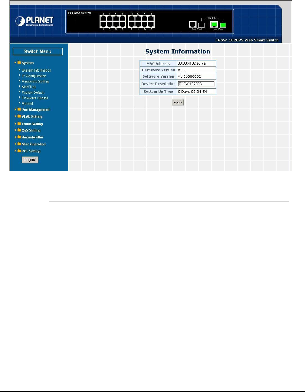
4.2.1 System Information
This section displays the MAC address, Hardware Version, Software Version and System Up Time, also allow define the
device description and press “Apply” button to take affect. The screen in Figure 4-4 appears.
Figure 4-4 System Information Web Page Screen
#Notice: Up to 16 characters is allowed for the Device Description.
- 18 -
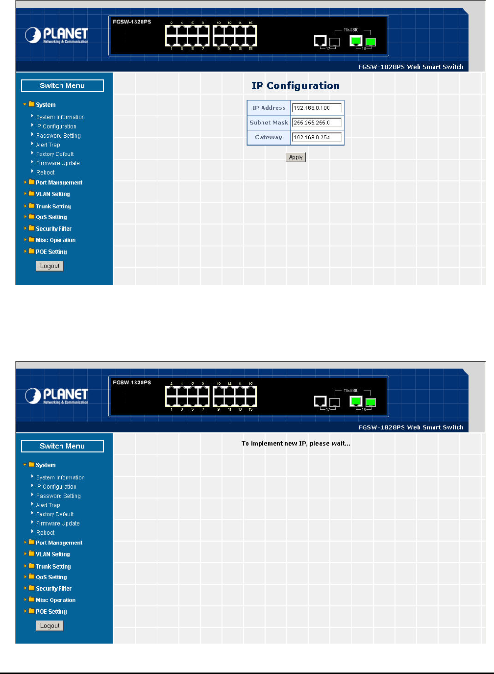
4.2.2 IP Configuration
This section provides change the IP Address, Subnet Mask and Gateway, the screen in Figure 4-5 appears.
Figure 4-5 IP Configuration Web Page Screen
After setup complete and press “Apply” button to take affect. The following screen in Figure 4-6 appears and then another
Web page login screen with new IP address will show up. After input correct username and password then can continue the
Web Smart PoE Switch management.
Figure 4-6 IP Configuration Web Page Screen

- 19 -
4.2.3 Password Setting
This section provides change the Username and Password, the screen in Figure 4-7 appears.
Figure 4-7 Password Setting Web Page Screen
#Notice: Up to 8 characters is allowed for the username and password assign.
- 20 -
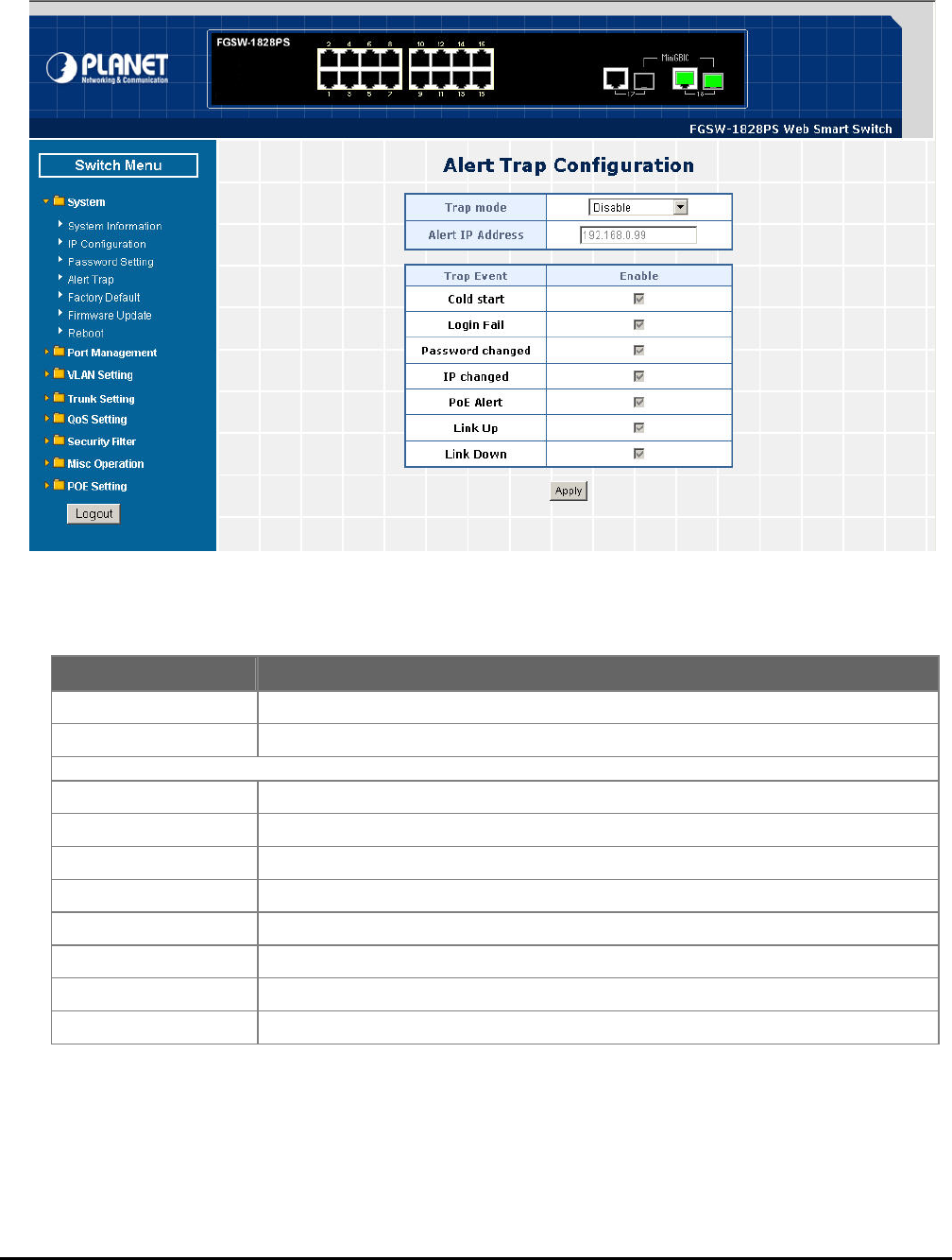
4.2.4 Alert Trap
This section provides Web Smart PoE Switch Alert Trap configuration, such as Disable or enable the trap mode and alert
IP address assign the screen in Figure 4-8 appears. The table 4-2 describes the Alert Trap object of Web Smart PoE
Switch.
Figure 4-8 Alert Trap Web Page Screen
Table 4-2 Descriptions of the Alert Trap Web Page Screen Objects
Object Description
Trap mode Allow disable or enable the Alert Trap mode.
Alert IP Address Allow assign an Alert IP Address of one specific workstation that gets SNMP Trap.
Trap Event
Cold start Choose this event then can get Cold Start Trap.
Login Fail Choose this event then can get Login Fail Trap.
Password Changed Choose this event then can get Password Changed Trap.
IP Changed Choose this event then can get IP address Changed Trap.
PoE Alert Choose this event then can get link up / link down Trap from each PoE port.
Link Up Choose this event then can get link up trap from each Ethernet port.
Link Down Choose this event then can get link down trap from each Ethernet port.
Apply Press this button to take affect.
- 21 -
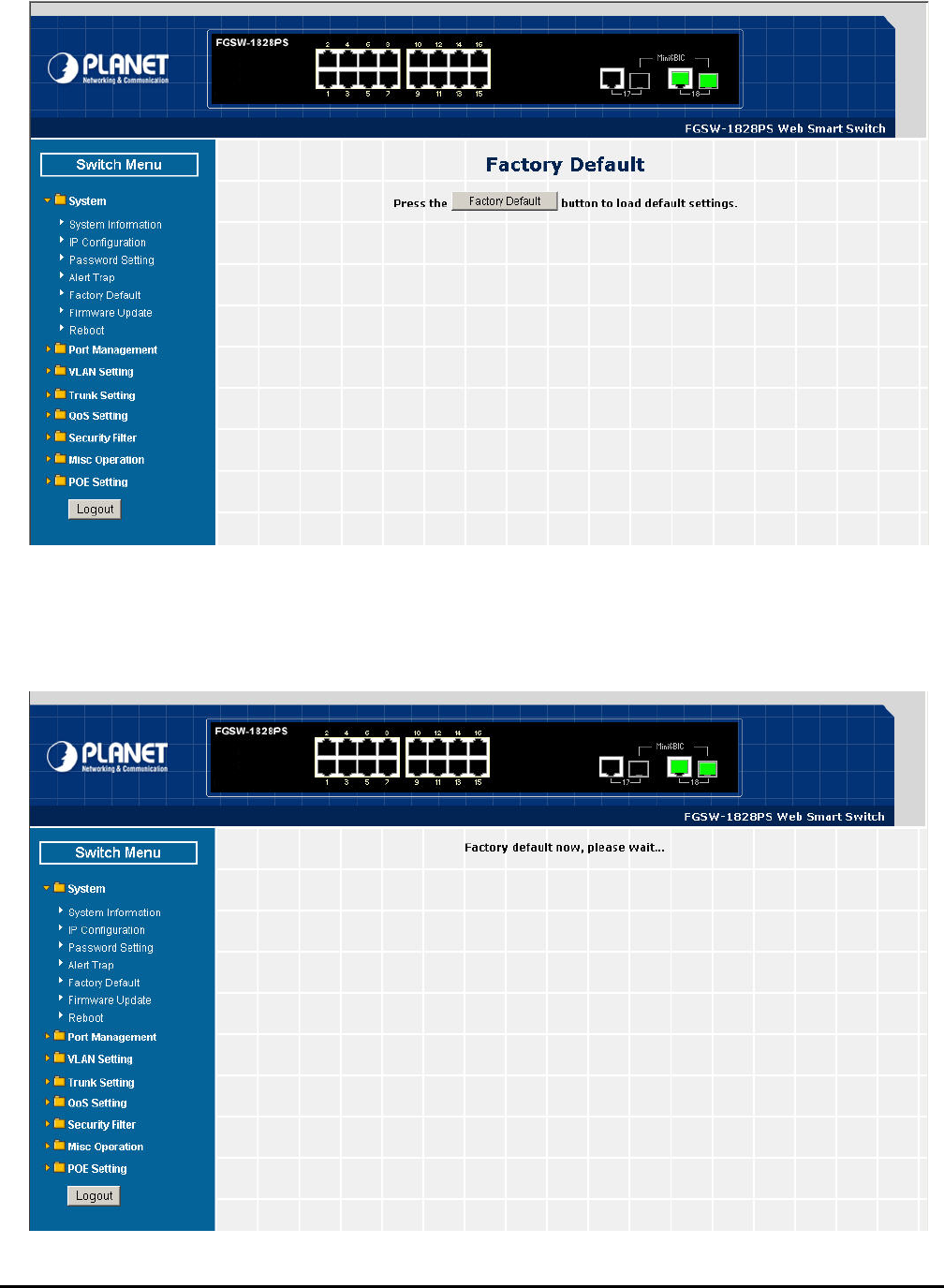
4.2.5 Factory Default
This section provides reset the Web Smart PoE Switch to factory default mode, the screen in Figure 4-9 appears.
Figure 4-9 Factory Default Web Page Screen
Press “Factory Default” button to take affect. The following screen in Figure 4-10 appears and then another Web page
login screen with default setting will show up. After input default username and password then can continue the Web Smart
PoE Switch management.
Figure 4-10 Factory Default Web Page Screen
- 22 -
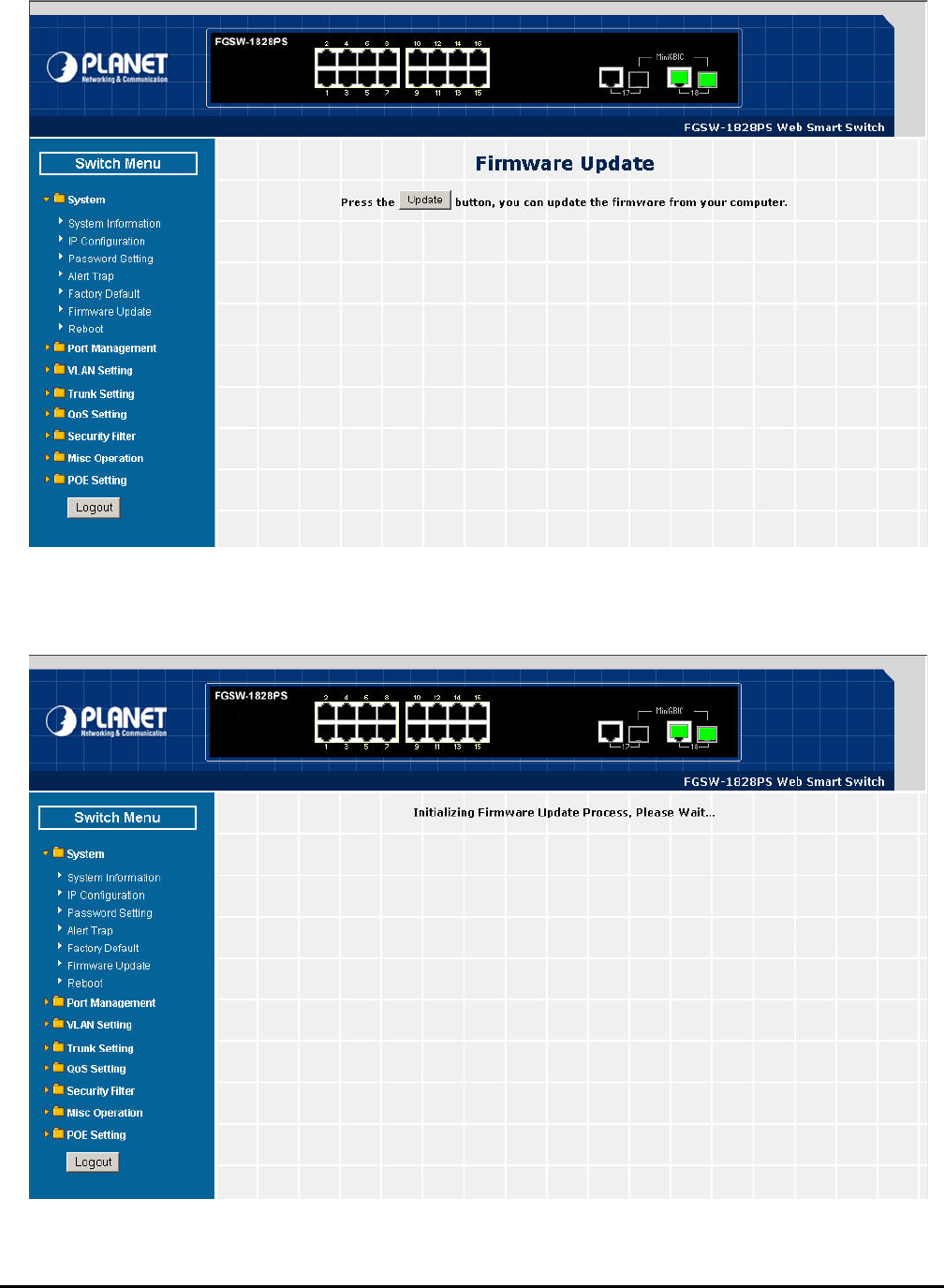
4.2.6 Firmware Update
This section provides firmware upgrade of the Web Smart PoE Switch, the screen in Figure 4-11 appears.
Figure 4-11 Firmware Update Web Page Screen
ress “Update” button for start the firmware upgrade process, the screen in Figure 4-12 & 4-13 appears. P
Figure 4-12 Firmware Update Web Page Screen
- 23 -
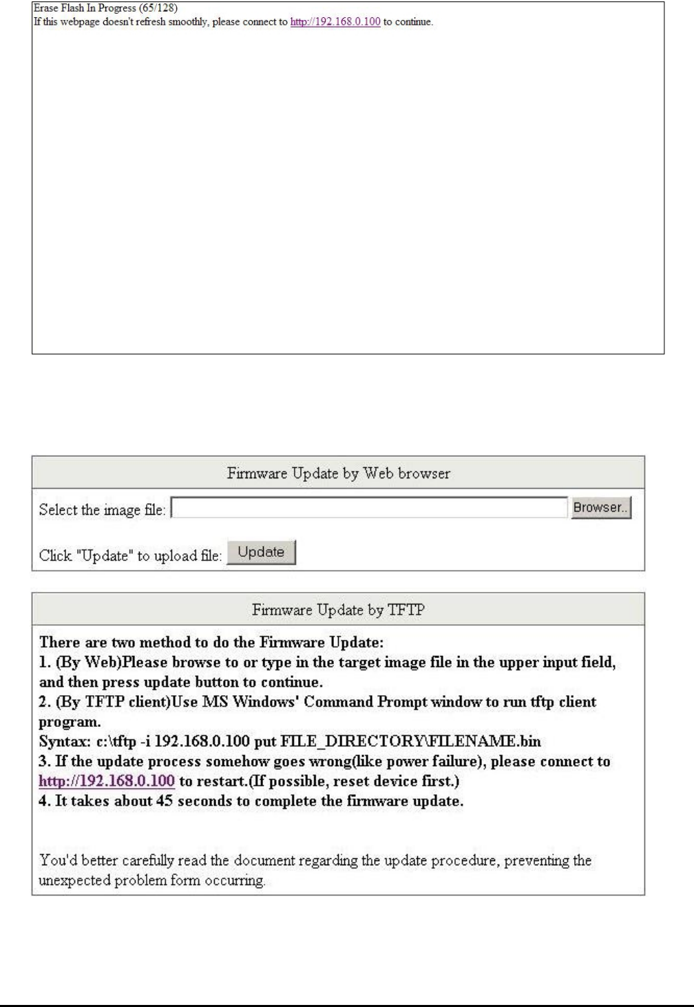
Figure 4-13 Firmware Update Web page Screen
Then the following screen appears, on administrator PC, the screen in
Figure 4-14 appears.
press “Browser” button to find the firmware locati
Figure 4-14 Firmware Update Web Page Screen

- 24 -
After find the firmware location from administrator PC, press “Update” button to start the firmware upgrade process. The
W se wait for a while for system reboot.
screen in Figure 4-15 appears.
Figure 4-15 Firmware Update Web Page Screen
hen firmware upgrade process is completed then the following screen appears, plea
After device reboot then can use the latest firmware of the Web Smart PoE Switch.
Figure 4-16 Firmware Update Web Page Screen
- 25 -
#Notice: Recommend to use IE 6.0 browser for firmware upgrade process.
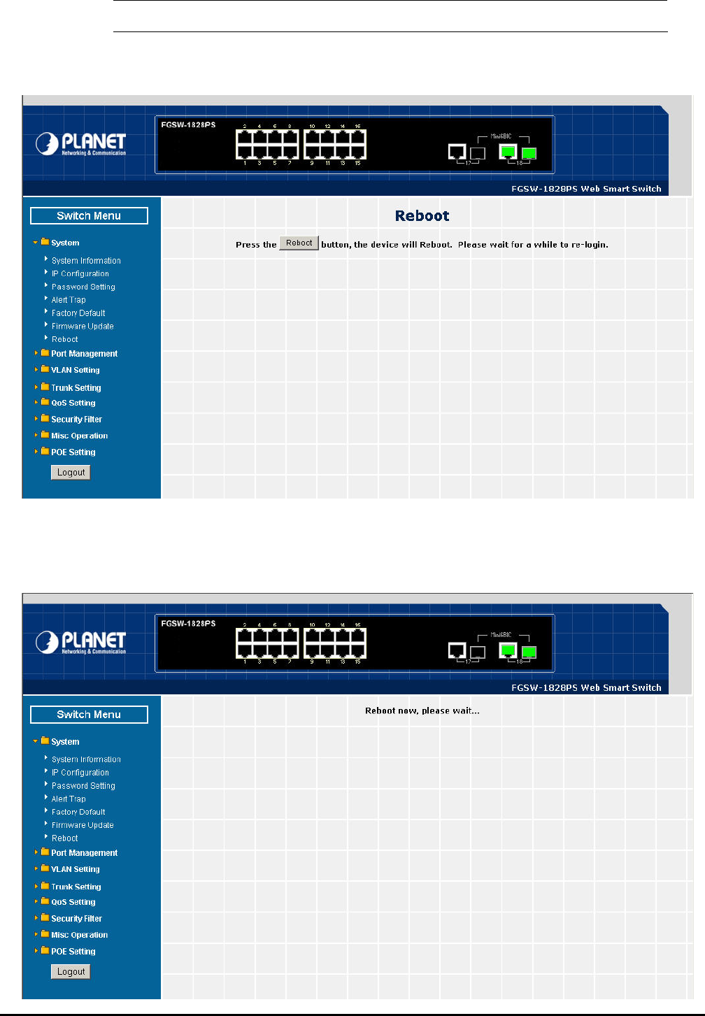
4.2.7 Reboot
s reboot the Web Smart PoE Switch, the screen in Figure 4-17 appears. This section allow
Figure 4-17 Reboot Web Page Screen
ress “Reboot” button to reboot the Web Smart PoE Switch, the screen in Figure 4-18 appears. After device reboot P
completed, the Web login screen appears and login for further management.
- 26 -
Figure 4-18 Reboot Web Page Screen
4-3 Port Management
This section provides Port Configuration, Port Mirroring, Bandwidth Control, Broadcast Storm Control and Port Statistics
from Web Smart PoE Switch, the screen in Figure 4-19 appears and table 4-3 describes the Port Management object of
Web Smart PoE Switch.
Figure 4-19 Port Management Web Page Screen
Table 4-3 Descriptions of the Port Management Web Page Screen Objects
Object Description
Port Configuration Allow to configure each port of Web Smart PoE Switch. Explained in section 4.3.1.
Port Mirroring Allow to use port mirroring function of Web Smart PoE Switch. Explained in section 4.3.2.
Bandwidth Control Allow to configure bandwidth control of each port from Web Smart PoE Switch. Explained
in section 4.3.3.
Broadcast Storm Control Allow to configure broadcast storm control of each port from Web Smart PoE Switch. Ex-
plained in section 4.3.4.
Port Statistics Display each port statistics of Web Smart PoE Switch. Explained in section 4.3.5.
- 27 -
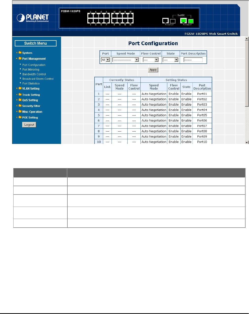
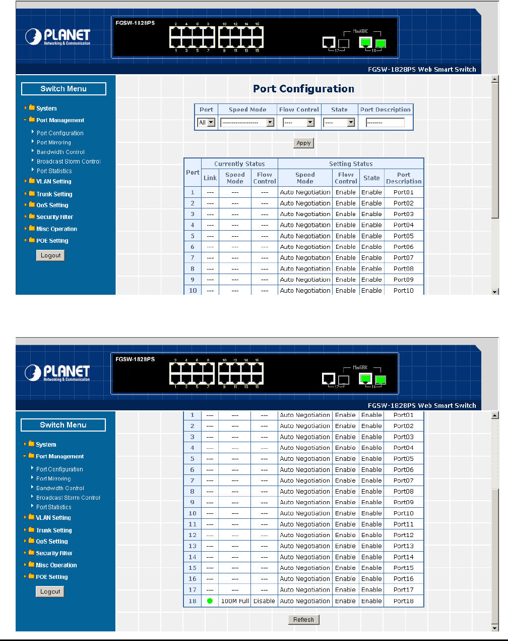
4.3 iguration
Thi etail s
table 4-4 & 4-5 n objects of Web Smart PoE Switch.
.1 Port Conf
s section introduces d ettings of per port on Web Smart PoE Switch; the screen in Figure 4-20 & 4-21 appears and
e Port Configuratio descriptions th
Figure 4-20 Port Configuration Web Page Screen

- 28 -
Figure 4-21 Port Configuration Web Page Screen
Table 4-4 Descriptions of the Port Configuration Web Page Screen Objects
cts
Table 4-5 Descriptions of the Port Configuration Web Page Screen Obje
Object Description
Port Allow choosing all or one port of Web Smart PoE Switch for further management, the
available options is All & 01 to 16 (FNSW-1608PS). Or All & 01 to 18 (FGSW-1828PS).
Speed Mode Allow choosing various speed duplex mode from one specific port of Web Smart PoE
Switch , the available options are shown as below:
Auto Negotiation
1000Full (FGSW-1828PS 1000Mbps Port Only )
100Full
100Half
10Full
10Half
Default mode is Auto Negotiation.
Flow Control Allow to configure Flow control function of each port from Web Smart PoE Switch, the
available options are Enable and Disable. Default mode is Enable.
State Allow disable or enable one specific port from Web Smart PoE Switch, the available options
are Enable and Disable. Default mode is Enable.
Port Description Allow input per Port Description of Web Smart PoE Switch, up to maximum 8 characters
allow.
Apply button Press “Apply” button for save current configuration of each port on Web Smart PoE
Switch.
Object Description
Port Indicate port 1 to port 16 (FNSW-1608PS), port 1 to port 18 (FGSW-1828PS).
Current Status d Mode and Flow Control. Display per port Current Status, such as Link, Spee
Link status from each port of the Web Smart PoE Switch. Display current link
Speed Mode eb Smart PoE Switch. Display current speed mode from each port of the W
Flow Control urrent flow control status from each port of the Web Smart PoE Switch. Display c
Setting Status s, such as Speed Mode, Flow Control, State and Port Display per port Current Setting Statu
Description.
Speed Mode Display per port Speed Mode setting value.
Flow Control Display per port Flow Control setting value.
State Display per port State setting value.
Port Description per Port Description. Display
Refresh button Press “Refresh” button to refresh current status.
- 29 -
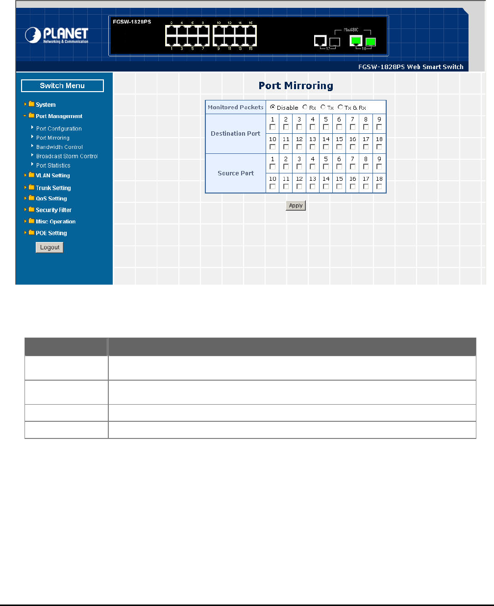
4.3.2 Port Mirroring
Thi on introduces detail s Figure 4-22
app 4-6 descript
s secti ettings of Port Mirroring function of Web Smart PoE Switch; the screen in
ears and table ions the Port Mirroring objects of Web Smart PoE Switch.
Table 4-6 Descriptions of the Port Mirroring Screen Objects
Figure 4-22 Port Mirroring Web Page Screen
Object Description
Monitored Packets Provide disable and enable the Port Mirroring function, the available options are Disable, RX,
TX, TX & RX. Default mode is Disable.
Destination Port The destination port can be used to see all monitor port traffic. It can connect destination port to
LAN analyzer or Netxray.
Source Port The source port that want to monitor. All monitor port traffic will be copied to destination port.
Apply button Press this button for save current configuration of Web Smart PoE Switch.
- 30 -
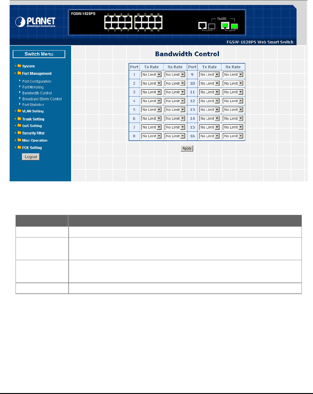
4.3.3 Bandwidth Control
This section introduces detail settings of Bandwidth Control function of Web Smart PoE Switch; the screen in Figure 4-23
appears and table 4-7 description the Bandwidth Control objects of Web Smart PoE Switch.
Figure 4-23 Bandwidth Control Web Page Screen
Table 4-7 Descriptions of the Bandwidth Control Screen Objects
Object Description
Port Indicate port 1 to port 16 of Web Smart PoE Switch.
Tx Rate Provide No Limit, 1Mbps, 2Mbps, 4Mbps, 8Mbps, 16Mbps, 32Mbps, 64Mbps different
transmit rate for bandwidth control function of Web Smart PoE Switch. Default mode is “No
Limit”.
Rx Rate Provide No Limit, 1Mbps, 2Mbps, 4Mbps, 8Mbps, 16Mbps, 32Mbps, 64Mbps different re-
ceive rate for bandwidth control function of Web Smart PoE Switch. Default mode is “No
Limit”.
Apply button Press this button for save current configuration of each port on Web Smart PoE Switch.
- 31 -
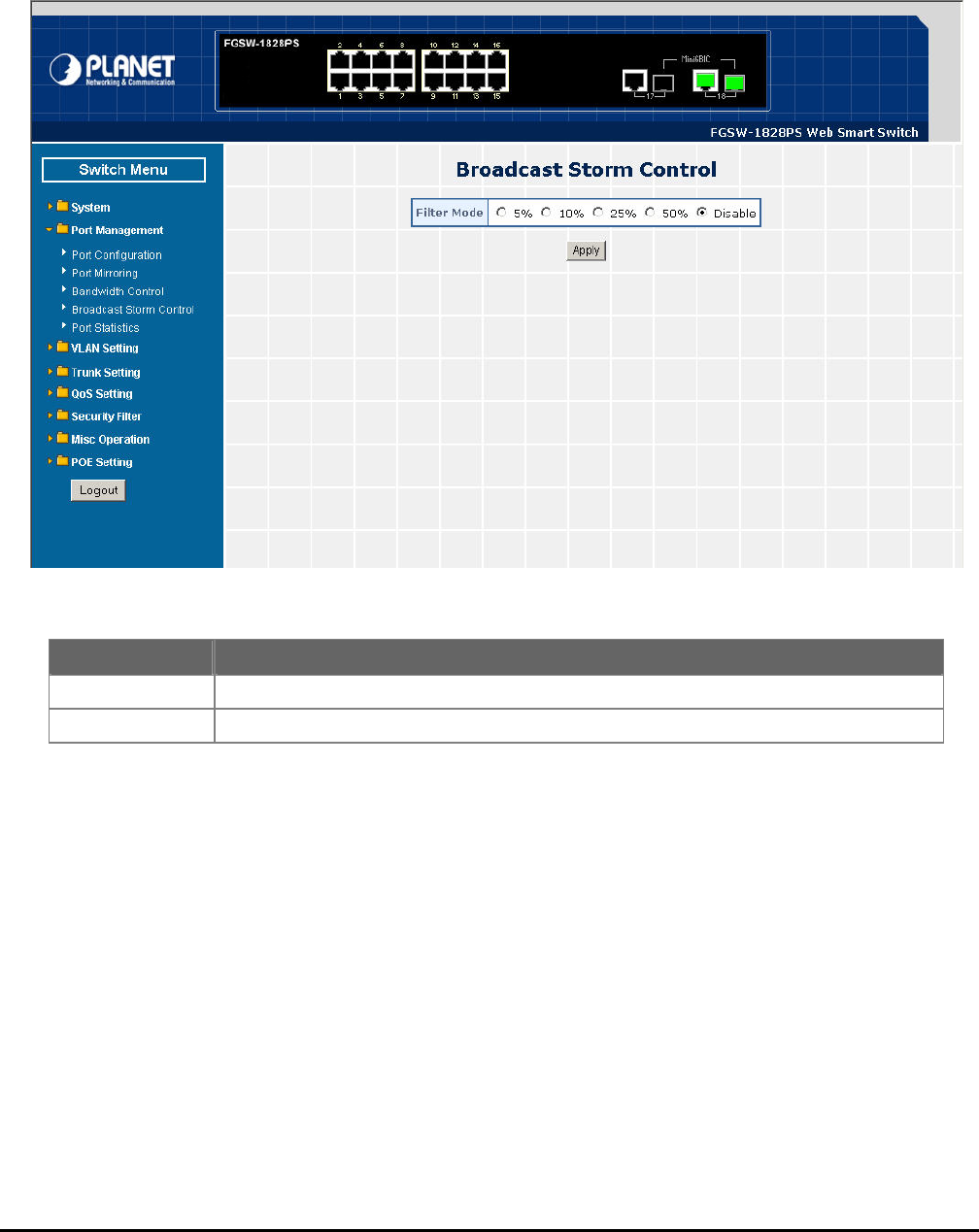
4.3.4 Broadcast Storm Control
This section introduces detail settings of Broadcast Storm Control function of Web Smart PoE Switch; the screen in Figure
4-24 appears and table 4-8 descriptions the Broadcast Storm Control objects of Web Smart PoE Switch.
Figure 4-24 Broadcast Storm Control Web Page Screen
Table 4-8 Descriptions of the Broadcast Storm Control Screen Objects
Object Description
Filter Mode 5%, 10%, 25%, 50%, Disable different filter mode. Default mode is Disable. Provide
Apply button Press this button for save current configuration of Web Smart PoE Switch.
- 32 -
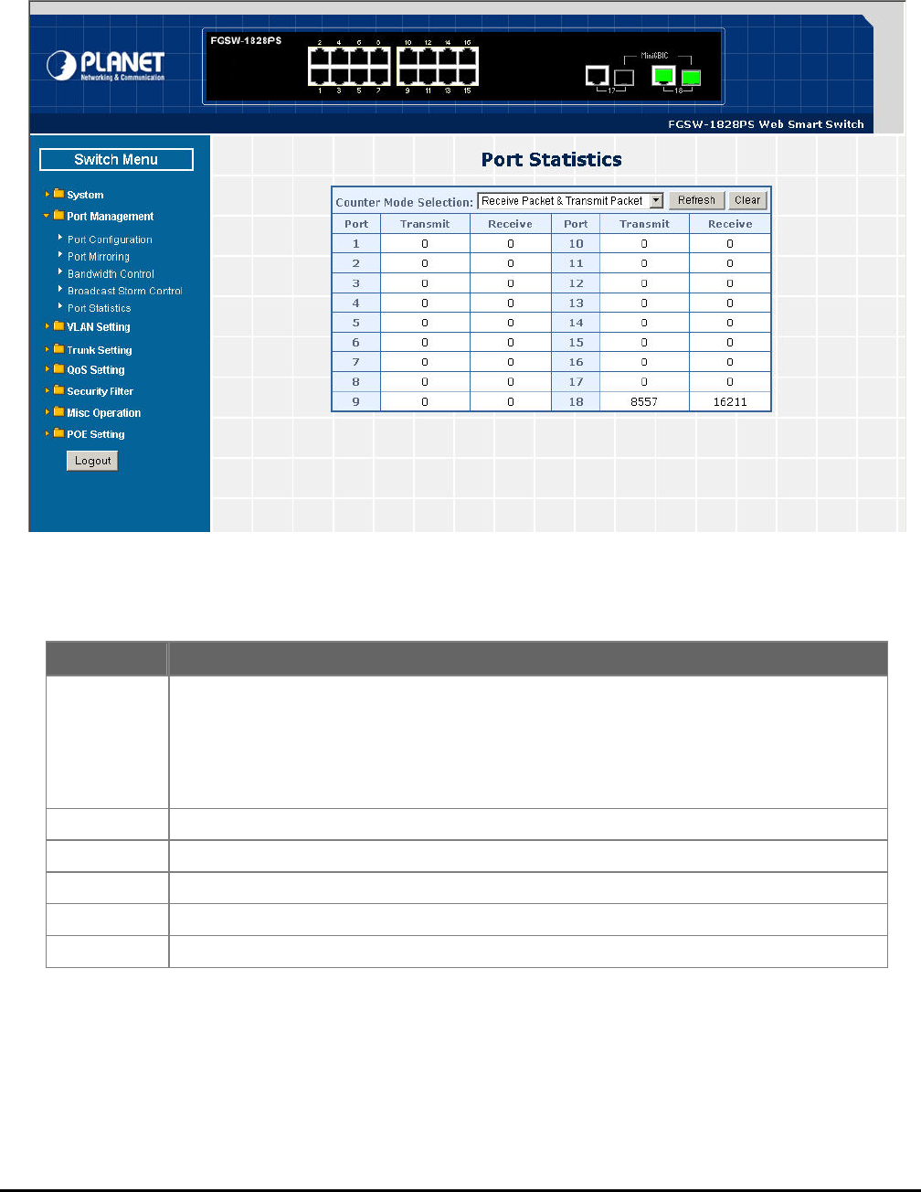
4.3.5 Port Statistics
This section introduces detail information of Port Statistics function of Web Smart PoE Switch; the screen in Figure 4-25
appears and table 4-9 descriptions the Port Statistics objects of Web Smart PoE Switch.
Table 4-9 Descriptions of the Port Statistics Screen Objects
Figure 4-25 Port Statistics Web Page Screen
Object Description
Counter Mode
Selection Provide different type of Ethernet traffic counter mode, the available options are shown as below:
Receive Packet & Transmit Packet
collision Count & Transmit Packet
Drop Packet & Receive Packet
CRC error Packet & Receive Packet
Default mode is Receive Packet & Transmit Packet.
Port Indicate port 1 to port 16 (FNSW-1608PS), port 1 to port 18 (FGSW-1828PS).
Transmit Display Transmit count value from each port.
Receive Display Receive count value from each port.
Refresh button Press this button for refresh the Port Statistics value of Web Smart PoE Switch.
Clear button Press this button for clear the Port Statistics value of Web Smart PoE Switch.

- 33 -
4-4 VLAN Setting
A Virtual LAN (VLAN) is a logical network grouping that limits the broadcast domain. It allows you to isolate network traffic
so only members of the VLAN receive traffic from the same VLAN members. Basically, creating a VLAN from a switch is
logically equivalent of reconnecting a group of network devices to another Layer 2 switch. However, all the network devices
are still plug into the same switch physically.
The Switch supports IEEE 802.1Q (tagged-based) and Port-Base VLAN setting in web management page. In the default
configuration, VLAN support is “No VLAN”.
Port-based VLAN
Port-based VLAN limit traffic that flows into and out of switch ports. Thus, all devices connected to a port are members of
the VLAN(s) the port belongs to, whether there is a single computer directly connected to a switch, or an entire department.
On port-based VLAN.NIC do not need to be able to identify 802.1Q tags in packet headers. NIC send and receive normal
Ethernet packets. If the packet's destination lies on the same segment, communications take place using normal Ethernet
protocols. Even though this is always the case, when the destination for a packet lies on another switch port, VLAN con-
siderations come into play to decide if the packet is dropped by the Switch or delivered.
IEEE 802.1Q VLANs
IEEE 802.1Q (tagged) VLAN are implemented on the Switch. 802.1Q VLAN require tagging, which enables them to span
the entire network (assuming all switches on the network are IEEE 802.1Q-compliant).
VLAN allow a network to be segmented in order to reduce the size of broadcast domains. All packets entering a VLAN wil
only be forwarded to the stations (over IEEE 802.1Q enabled switches) that are members of that VLAN, and this includes
roadcast, multicast and unicast packets from unknown sources.
LAN can also provide a level of security to you ackets between stations
at are members of the VLAN. Any port can be configured as either tagging or untagging. The untagging feature of IEEE
802.1Q VLAN allows VLAN to work with legacy switches that don't recognize VLAN tags in packet headers. The tagging
feature allow 802.1Q-compliant sw single physical connection and allows Span-
nin enabled on all ports and work normally.
An to
wo cy sw he tagging feature allows VLAN to span
multiple 802.1Q-co cal connection and allows Spanning Tree to be enabled on all
ports and work norm
Some relevant term
he act of acket.
- The act of stripping 802.1Q VLAN
80 N Tags
Th rce MAC address.
Th field is equal to
0x et ctets and consists of 3
bits of user priority, 1 bit of Canonical F can be
carried across Ethernet backbo 802.1p. The VID
the VLAN identifier and is us 094 unique VLAN can be
entified.
he tag is inserted into the packet header making the entire packet longer by 4 octets. All of the information originally
ontained in the packet is retained.
l
b
V
th
r network. IEEE 802.1Q VLAN will only deliver p
s VLAN to span multiple
g Tree to be
itches through a
y port can be con
rk with lega
figured as either tagging or untagging. The untagging feature of IEEE 802.1Q VLAN allows VLAN
itches that don’t recognize VLAN tags in packet headers. T
mpliant switches through a single physi
ally.
s:
Tag - T
Untag
putting 802.1Q VLAN information into the header of a p
information out of the packet header.
2.1Q VLA
e figure below sh
eir presence is in
ows the 802.1Q VLAN tag. There are four additional octets inserted after the sou
dicated by a value of 0x8100 in the Ether Type field. When a packet's Ether Type
8100, the pack carries the IEEE 802.1Q/802.1p tag. The tag is contained in the following two o
ormat Identifier (CFI - used for encapsulating Token Ring packets so they
nes), and 12 bits of VLAN ID (VID). The 3 bits of user priority are used by
ed by the 802.1Q standard. Because the VID is 12 bits long, 4is
id
T
c
- 34 -
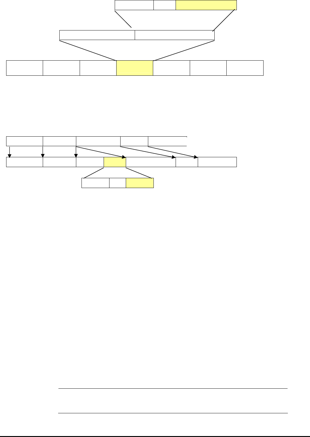
802.1Q Tag
User Priority CFI VLAN ID (VID)
3 bits 1 bits 12 bits
TPID (Tag Protocol Identifier) TCI (Tag Control Information)
2 bytes 2 bytes
Preamble Destination
Address
Source Ad-
dress VLAN TAG Ethernet
Type Data FCS
6 bytes 6 bytes 4 bytes 2 bytes 46-1517 bytes 4 bytes
The Ether Type and VLAN ID are inserted after the MAC source address, but before the original Ether Type/Length or
Logical Link Control. Because the packet is now a bit longer than it was originally, the Cyclic Redundancy Check (CRC)
must be recalculated.
Adding an IEEE802.1Q Tag
Dest. Addr. Src. Addr. Length/E. type Data Old CRC
Dest. Addr. Src. Addr. E. type Tag Length/E. type Data New CRC
Priority CFI VLAN ID
Port VLAN ID
Packets that are tagged (are carrying the 802.1Q VID information) can be transmitted from one 802.1Q compliant network
device to another with the
VLAN information intact. This allows 802.1Q VLAN to span network devices (and indeed, the
twork devices are 802.1Q compliant).
Ev D, for use within the switch. If no VLAN
ar equal to 1. Untagged packets are
assigned the PVID of the port on which they were received. Forwarding decisions are based upon this PVID, in so far as
Tagged packets are forwarded according to the VID contained within the tag. Tagged packets are
is not used to make packet forwarding decisions, the VID is.
rt can have only one PVID, but can have as many VID as the switch has memory in its VLAN table to store them.
may be tag-unaware, a decision must be made at each port on a tag-aware device
before packets are transmitted – should the packet to be transmitted have a tag or not? If the transmitting port is connected
to a tag-unaware device, the packet should be untagged. If the transmitting port is connected to a tag-aware device, the
packet should be tagged.
Default VLANs
The Switch initially configures one VLAN, VID = 1, called "default." The factory default setting assigns all ports on the
Switch to the "default". As new VLAN are configured in Port-based mode, their respective member ports are removed
from the "default."
#Notice: Base on the Switch chipset specification, the Switch supports SVL(Shared VLAN Learning) ,
all VLAN groups share the same Layer 2 learned MAC address table.
entire network – if all ne
ery physical port on a switch has a PVID. 802.1Q ports are also assigned a PVI
e defined on the switch, all ports are then assigned to a default VLAN with a PVID
VLAN are concerned.
also assigned a PVID, but the PVID
Tag-aware switches must keep a table to relate PVID within the switch to VID on the network. The switch will compare the
VID of a packet to be transmitted to the VID of the port that is to transmit the packet. If the two VID are different the switch
will drop the packet. Because of the existence of the PVID for untagged packets and the VID for tagged packets, tag-aware
and tag-unaware network devices can coexist on the same network.
A switch po
Because some devices on a network
Original Ethernet
New Tagged Packet
- 35 -
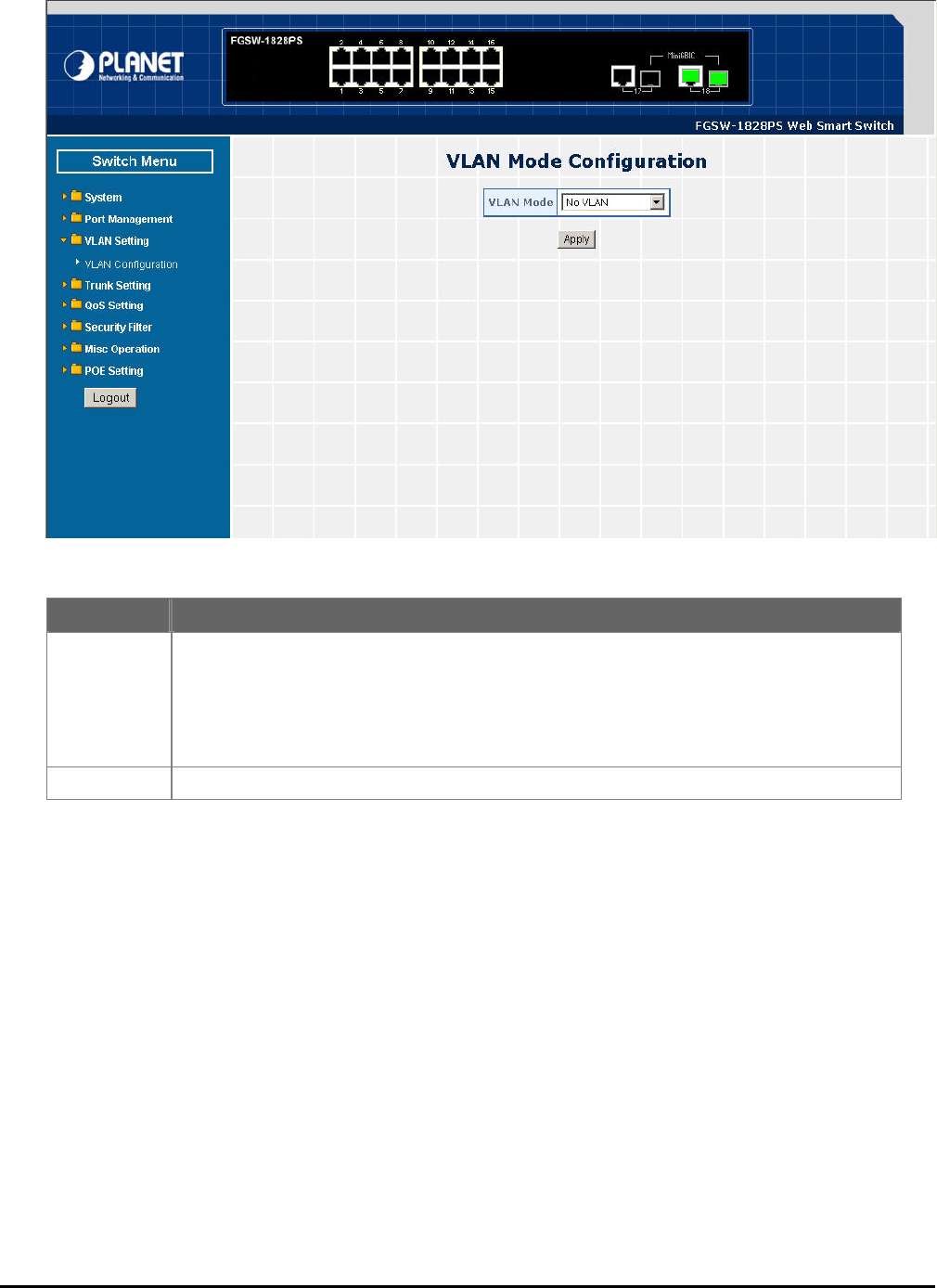
This section provides VLAN Configuration from Web Smart PoE Switch, the screen in Figure 4-26 appears and table
4-10 describes the VLAN Setting object of Web Smart PoE Switch.
Figure 4-26 VLAN Setting Web Page Screen
Table 4-10 Descriptions of the VLAN Setting Screen Objects
Object Description
VLAN Mode Provide different VLAN operation mode, the available options are shown as below:
No VLAN
802.1Q VLAN. Explained in section 4.4.1.
Port Based VLAN. Explained in section 4.4.2.
MTU. Explained in section 4.4.3.
Default mode is No VLAN.
Apply button Press this button for save current configuration of Web Smart PoE Switch.
- 36 -
4
This section introduces detail information of IEEE 802.1Q VLAN function of Web Smart PoE Switch; Choose “802.1Q
VLAN” from VLAN from the VLAN Mode and press “Apply” button to enable the 802.1Q VLAN function. The screen in
Figure 4-27 & 4-28 appears and table 4-11 description the 802.1Q VLAN objects of Web Smart PoE Switch.
.4.1 802.1Q VLAN
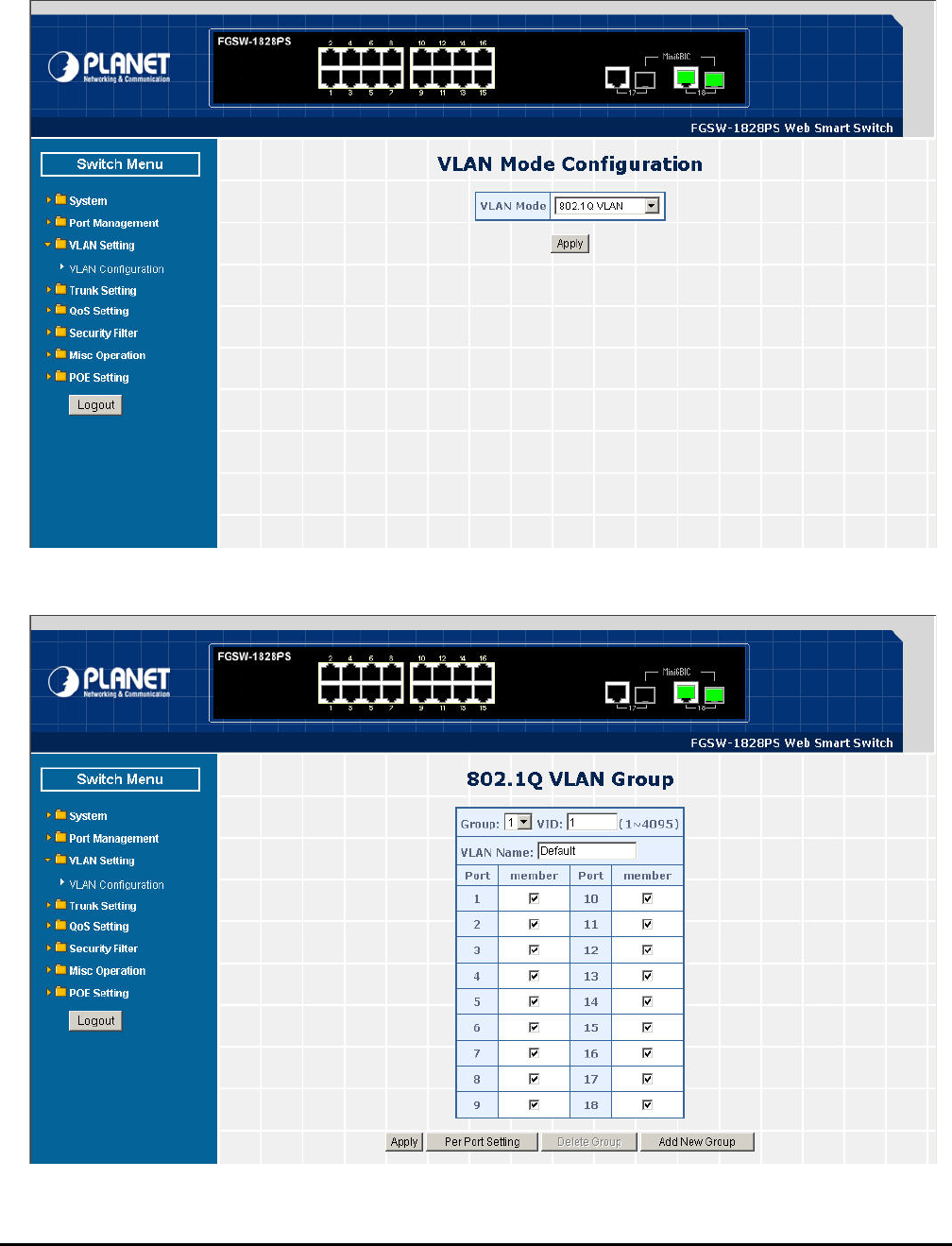
Figure 4-27 802.1Q VLAN Configuration Web Page Screen
802.1Q VLAN Configuration Web Page Screen
Figure 4-28
- 37 -
Table 4-11 Descriptions of the 802.1Q VLAN Setting Screen Objects
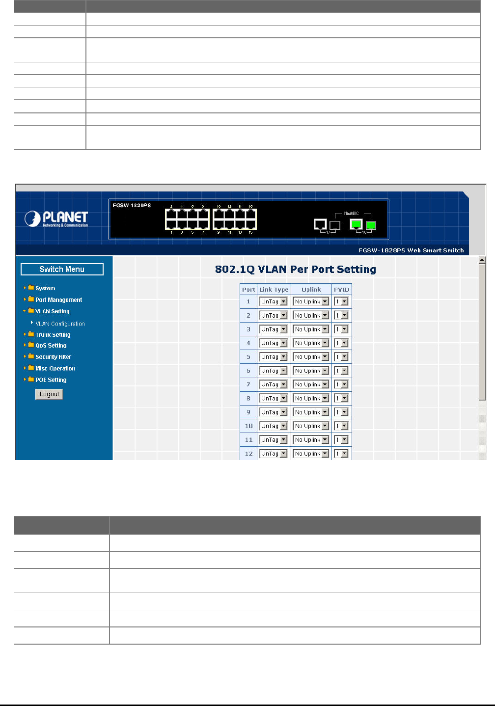
Figure 4-29 802.1Q VLAN per Port Setting Web Page Screen
This section introduces detail information of IEEE 802.1Q VLAN Per Port Setting of Web Smart PoE Switch; The table 4-12
description the 802.1Q VLAN Per Port Setting objects of Web Smart PoE Switch.
Table 4-12 Descriptions of the 802.1Q VLAN per Port Setting Screen Objects
Object Description
Group Display the existence 802.1Q VLAN groups.
VID Display different VLAN ID from multi-802.1Q VLAN groups.
VLAN Name Assign and display different VLAN name from multi-802.1Q VLAN groups. Up to maximum 8 char-
acters allow.
Port Indicate port 1 to port 16 (FNSW-1608PS), port 1 to port 18 (FGSW-1828PS).
Member Allow to click specific port as member port from different 802.1Q VLAN groups.
Apply button Press this button for save current configuration of Web Smart PoE Switch.
Per Port Setting Allow to define per port UnTag / Tag, Uplink and PVID. The screen in Figure 4-29 appears.
Delete Group Press this button for delete existence 802.1Q VLAN groups.
Add New Group Press this button for create a new 802.1Q VLAN groups. Up to maximum 32 802.1Q VLAN groups
support on Web Smart PoE Switch.
Object Description
Port Indicate port 1 to port 16 (FNSW-1608PS), port 1 to port 18 (FGSW-1828PS).
Link Type Define UnTag or Tag on each port of Web Smart PoE Switch. Default mode is “UnTag”.
Uplink Define No Uplink or Uplink on each port of Web Smart PoE Switch. Default mode is “No Up-
link”.
PVID Assign PVID on each port of Web Smart PoE Switch. Default PVID is “1”.
Apply button Press this button for save current configuration of Web Smart PoE Switch.
VLAN Group Setting Return to 802.1Q VLAN Group Setting screen.
- 38 -
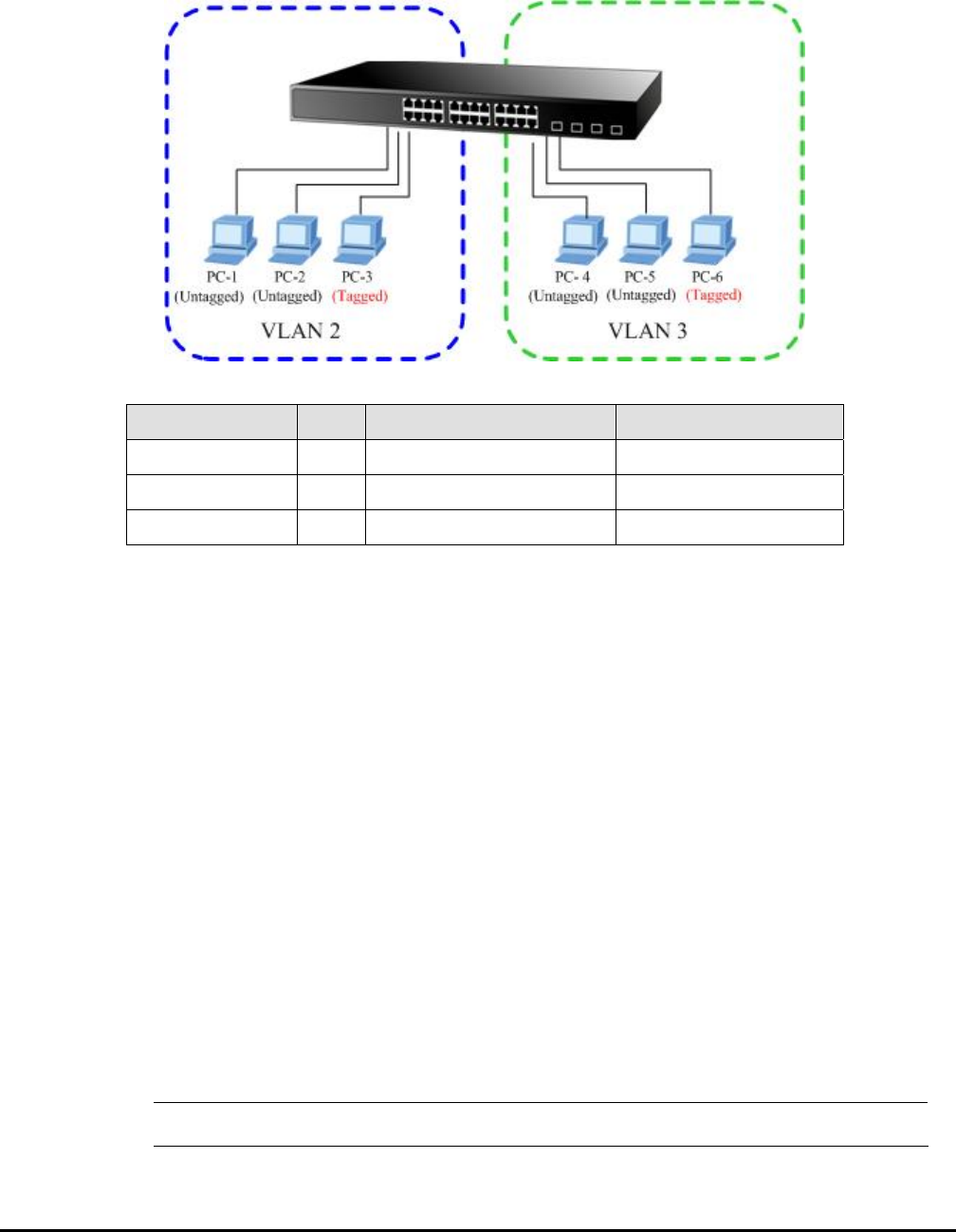
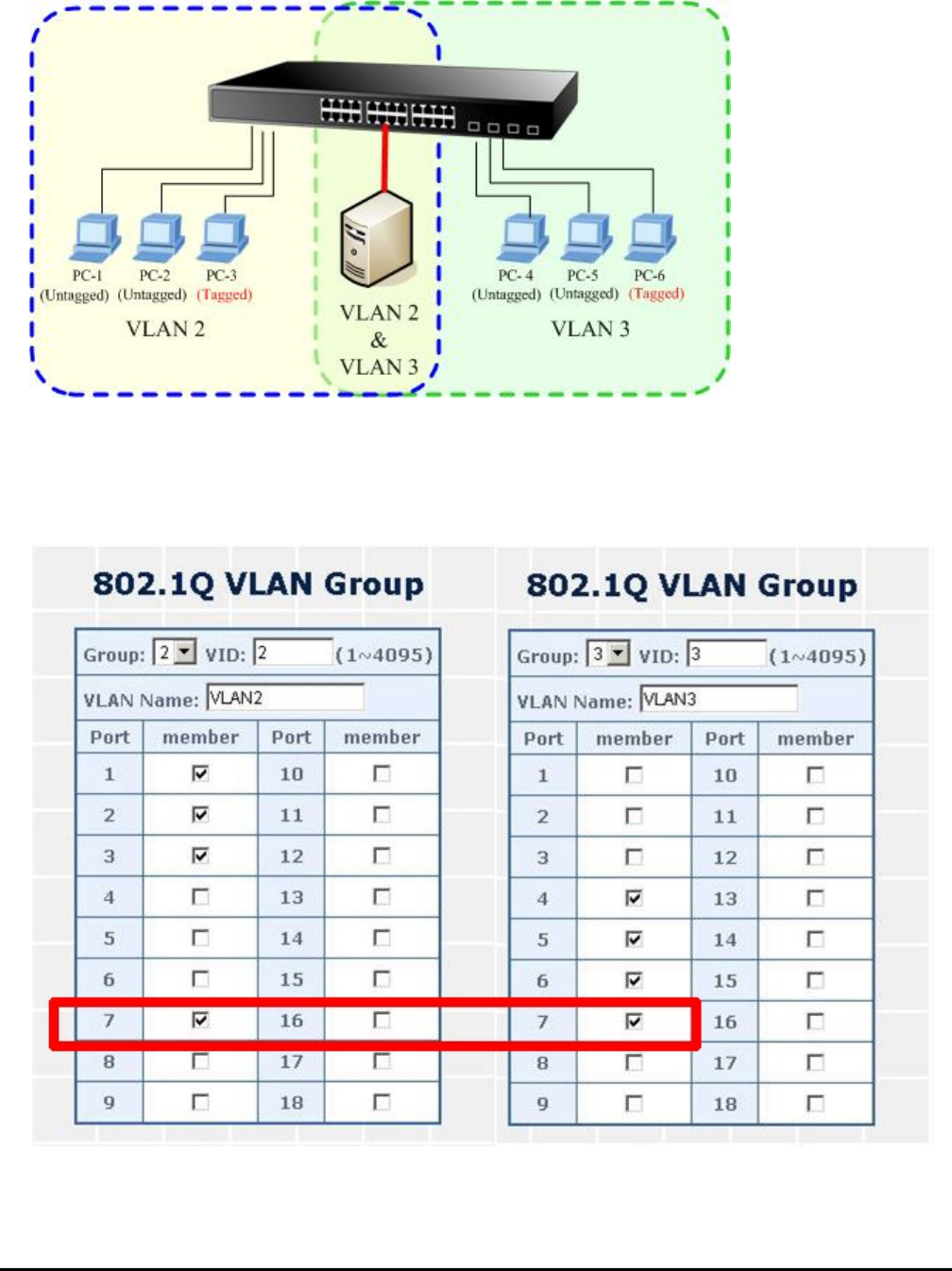
802.1Q VLAN Setting example:
Two separate 8
w th
2. Each VLAN is traffic, only the same VLAN member port can receive traffic from each other.
02.1Q VLAN scenario
1. Shows ho e Web Smart PoE Switch. Handles Untagged and Tagged traffic from two 802.1Q VLAN groups.
olate network
Figure 4-30 two separate 802.1Q VLAN diagram
VLAN Group VID Untagged Members Tagged Members
VLAN Group 1 1 Port-7~Port-18 N/A
VLAN Group 2 2 Port-1,Port-2 Port-3
VLAN Group 3 3 Port-4,Port-5 Port-6
Table 4-13 VLAN and Port Configuration
The scenario described as follow:
Untagged packet entering VLAN 2
1. While [PC-1] transmit an untagged packet enters Port-1, the Web Smart PoE Switch. Will tag it with a VLAN
Tag=2. [PC-2] and [PC-3] will received the packet through Port-2 and Port-3.
2. [PC-4], [PC-5] and [PC-6] received no packet.
3. While the packet leaves Port-2, it will be stripped away it tag becoming an untagged packet.
4. While the pack
, [PC-1] and [PC-2] will received the
ket through Port-1 and Port-2.
6. While the pa d packet.
While [PC-4] d
[PC-6] will r
ile the pa cket.
aket with VLAN Tag=3.
#Notice: fic flow.
et leaves Port-3, it will keep as a tagged packet with VLAN Tag=2.
Tagged packet entering VLAN 2
5. While [PC-3] transmit a tagged packet with VLAN Tag=2 enters Port-3
pac
cket leaves Port-1 and Port-2, it will be stripped away it tag becoming an untagge
Untagged packet entering VLAN 3
7. transmit an untagged packet enters Port-4, the switch will tag it with a VLAN Tag=3. [PC-5] an
eceived the packet through Port-5 and Port-6.
8. Wh cket leaves Port-5, it will be stripped away it tag becoming an untagged pa
9. While the p cket leaves Port-6, it will keep as a tagged pac
At this example, VLAN Group 1 just set as default VLAN, but only focus on VLAN 2, VLAN 3 traf

- 39 -
Setup steps
1. Create VLAN Group:
Set VLAN Group 1 = default-VLAN with VID (VLAN ID) =1.
Add two VLANs – VLAN 2 and VLAN 3, VLAN Group 2 with VID=2, VLAN Group 3 with VID=3.
Figure 4-31 Add new VLAN Group Screen
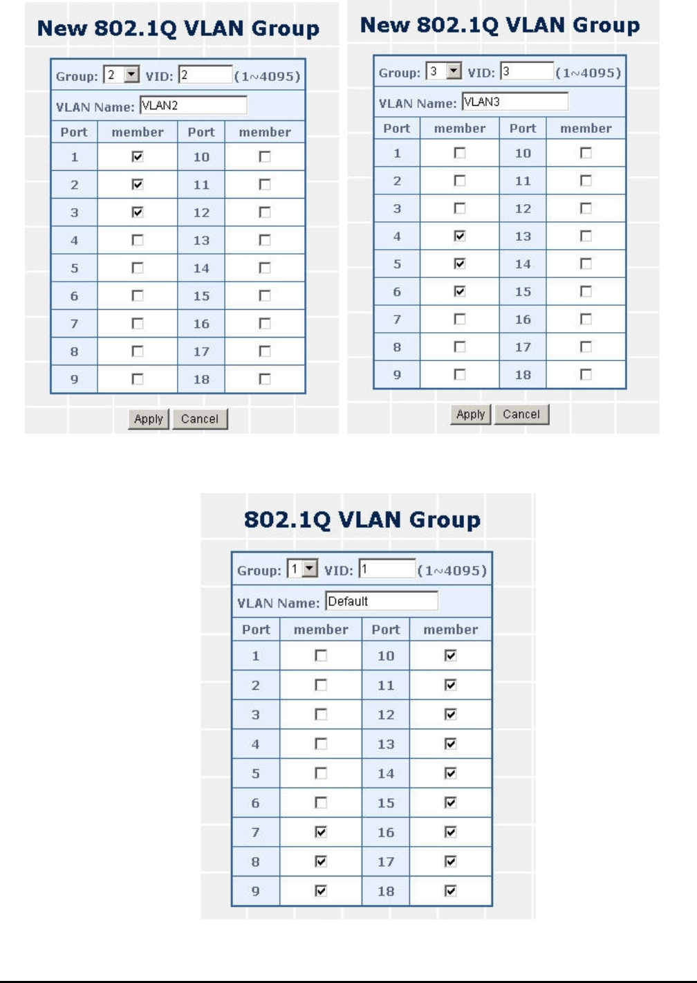
- 40 -
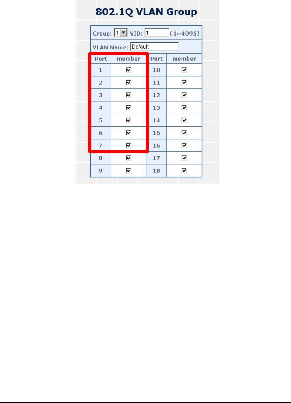
VLAN 2 : Port-1,Port-2 and Port-3. VLAN 3 : Port-4, Port-5 and Port-6. VLAN 1: All other ports – Port-7~Port-18.
Figure 4-32 Assign VLAN members for VLAN 2 and VLAN 3
Please remember to remove the Port 1 – Port 6 from VLAN 1 membership, since the Port 1 – Port 6 had been assigned to
VLAN 2 and VLAN 3.
Figure 4-33 Remove specify orts from VLAN 1 member p
2. Assign VLAN Member :
- 41 -
#Notice: ping setting.
Its import to remove the VLAN member port from VLAN 1 group. Or the ports would become overlap-
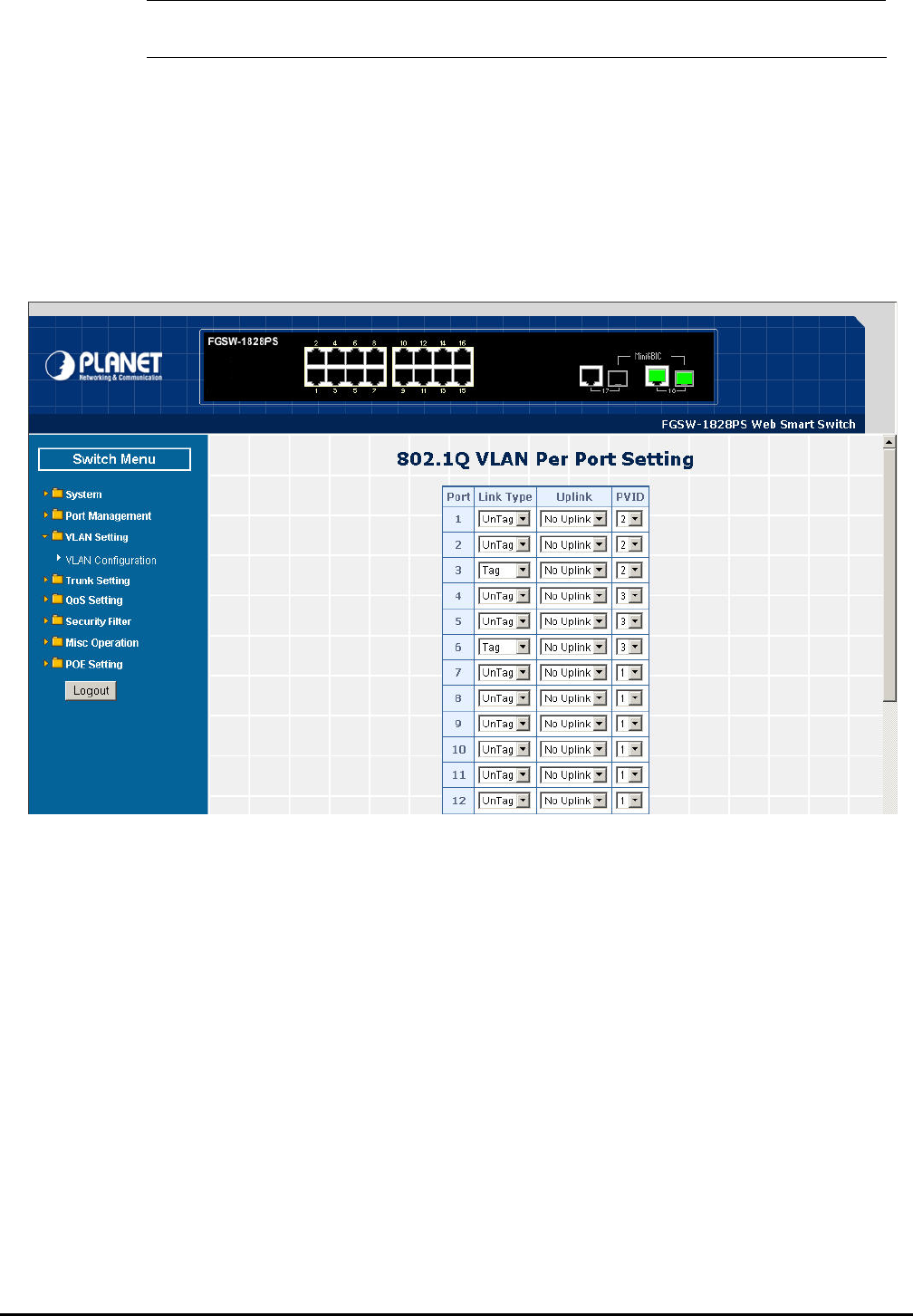
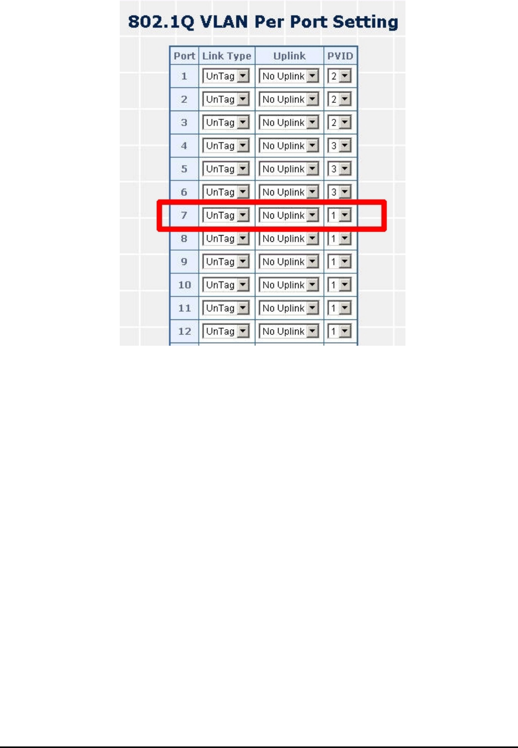
3. Assign PVID for each port:
Port-1,Port-2 and Port-3 : PVID=2.
Port-4,Port-5 and Port-6 : PVID=3.
Port-7~Port-18: PVID=1.
4. Enable VLAN Tag for specific ports
Link Type: Port-3 (VLAN-2) and Port-6 (VLAN-3).
The Per Port VLAN configuration in Figure 4-34 appears.
Figure 4-34 Port 1-Port 6 802.1Q VLAN Configuration
- 42 -
Two separate
1. Based on t te VLAN group example above, VLAN 2 and VLAN 3 member port cannot see each other.
2. The member ports from VLAN 2 and VLAN 3 need to access one public server.
802.1Q VLAN with overlapping area scenario
he two separa
Figure 4-35 A Server connect to the VLAN overlapping area
1. Specify Port-7 on the Web Smart PoE Switch that connects to the server.
2. Assign Port-7 to both VLAN 2 and VLAN 3 at the VLAN Member configuration page. The screen in Figure 4-36
appears.
Figure 4-36 VLAN overlap port setting
- 43 -
3. Define a VLAN 1 as a “Public Area” that overlapping with both VLAN 2 members and VLAN 3 members.
Figure 4-37 VLAN 1 – The public area member assign
4. Setup Port-7 with “PVID=1” at VLAN per Port Configuration page. The screen in Figure 4-38 appears.
- 44 -
Figure 4-38 Setup Port-7 with PVID-1
rt-3 and VLAN 3 members: Port-4 to PortAlthough the VLAN 2 members: Port-1 to Po -6 also belongs to VLAN 1. But with
different PVID settings, packets form VLAN 2 or VLAN 3 is not able to access to the other VLAN.
- 45 -
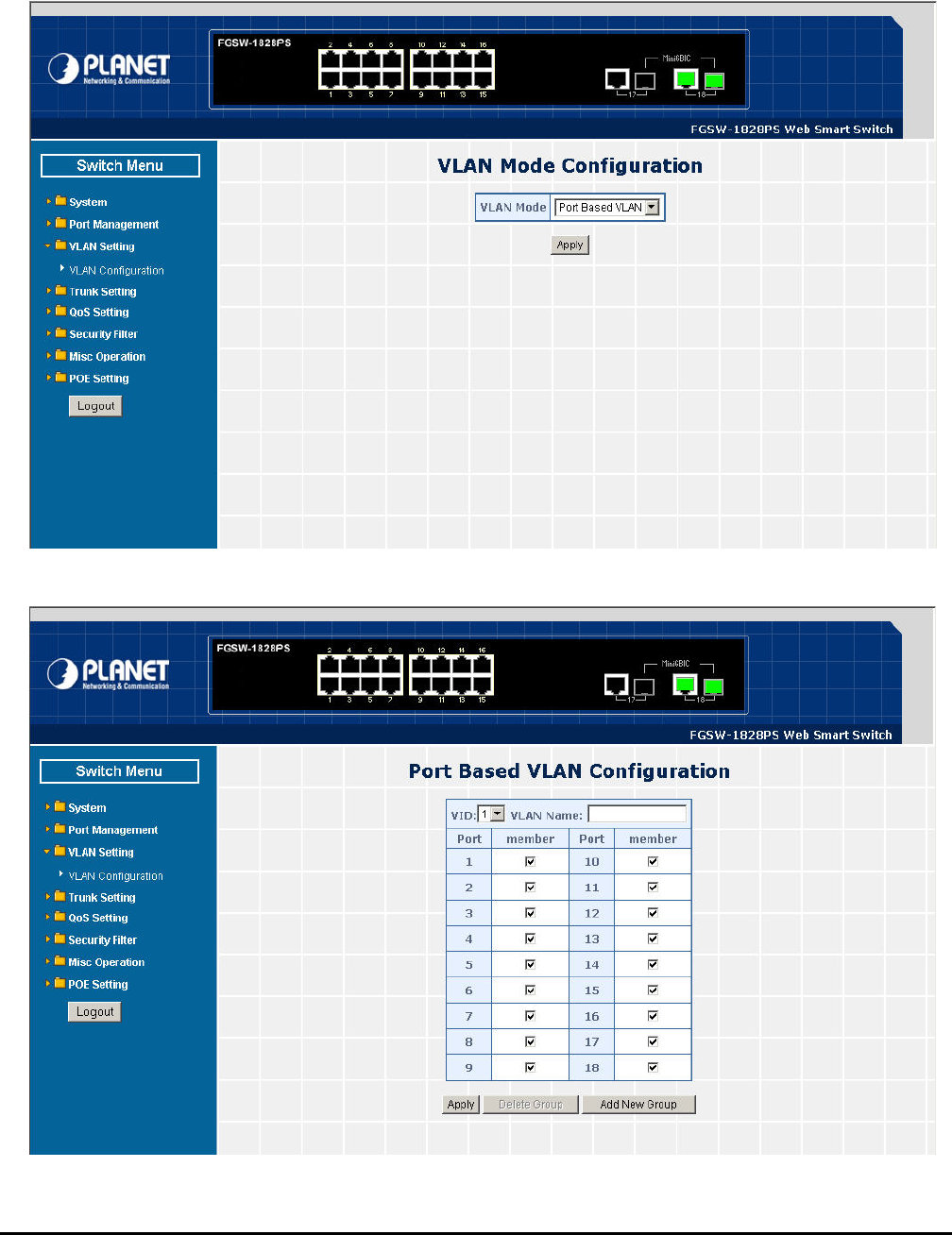
4.4.2 Port Based VLAN
This section introduces detail information of Port Based VLAN function of Web Smart PoE Switch; Choose “Port Based
VLAN” from VLAN from the VLAN Mode and press “Apply” button to enable the port based VLAN function. The screen in
Figure 4-39 & 4-40 appears and table 4-14 description the Port Based VLAN objects of Web Smart PoE Switch.
Figure 4-39 Port Based VLAN Configuration Web Page Screen
Figure 4-40 Port Based VLAN Configuration Web Page Screen

- 46 -
Table 4-14 Descriptions of the Port Based VLAN Configuration Screen Objects
Port Based VLAN Setting example:
VLAN scenario
1. Port 18 is the file server port for all the workstations
2. Port 1 to port 17 is different devices that do not need to see each other
Setup steps
1. Port Setting
1.1 Assign VLAN 1 for the first VLAN group with port 1 and port 18.
1.2 Assign VLAN 2 for the second VLAN group with port 2 and port 18
1.3 Repeat the same steps for port 3 to port 18. i.e. 3 & 18, 4 & 18….., 17 & 18
After the above steps port 1 to port N groups (different
LAN). However, they all can access port 18 due to port 18 is using overlapping feature to communicate with port 1 to port
17.
17 is being separated physically due to it belongs to different VLA
V
Object Description
VID Display different VLAN ID from multi-port based VLAN groups.
VLAN Name Assign and display different VLAN name from multi-port based VLAN groups. Up to maximum 8
characters allow.
Port Indicate port 1 to port 16 (FNSW-1608PS), port 1 to port 18 (FGSW-1828PS).
Member Allow to click specific port as member port from different port based VLAN groups.
Apply button Press this button for save current configuration of Web Smart PoE Switch.
Delete Group Press this button for delete existence port based VLAN groups.
Add New Group Press this button for create a new port based VLAN groups.

- 47 -
4.4.3 MTU VLAN
troduces detail information of MTU VLAN b Smart PoE Switch; Choose “MTU” from VLAN
the VLAN Mo The screen in Figure 4-41 appears and
description the MT
This section in function of We
from
table 4-15
de and press “Apply” button to enable the MTU VLAN function.
U VLAN objects of Web Smart PoE Switch.
Figure 4-41 MTU VLAN Configuration Web Page Screen
Table 4-15 Descriptions of the MTU VLAN Setting Screen Objects
Object Description
MTU Port Indicate the MTU Port of Web Smart PoE Switch.
Member Port Indicate the Member Port of Web Smart PoE Switch.
Apply button Press this button for save current configuration of Web Smart PoE Switch.
- 48 -
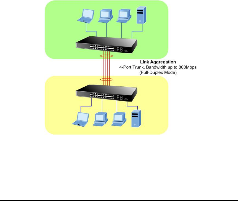
4-5 Trunk Setting
between devices, use the Link aggregation
e link aggregation on the devices at both ends. When using a port link aggregation, note
that:
。 The ports used in a link aggregation must all be of the same media type (RJ-45, 100 Mbps fiber).
。 The ports that can be assigned to the same link aggregation have certain other restrictions (see below).
。 Ports can only be assigned to one link aggregation.
。 The ports at both ends of a connection must be configured as link aggregation ports.
。 None of the ports in a link aggregation can be configured as a mirror source port or a mirror target port.
。 Enable the link aggregation prior to connecting any cable between the switches to avoid creating a data loop.
。 Disconnect all link aggregation port cables or disable the link aggregation ports before removing a port link aggre-
gation to avoid creating a data loop.
It allows a maximum of 4 ports to be aggregated at the same time and up to 2 groups. If the group is defined as a local static
link aggregation group, then the number of ports must be the same as the group member ports.
Port link aggregations can be used to increase the bandwidth of a network connection or to ensure fault recovery. Link
aggregation lets you group up to 4 consecutive ports into a single dedicated connection between any two the Switch or
other Layer 2 switches. However, before making any physical connections
Configuration menu to specify th
- 49 -
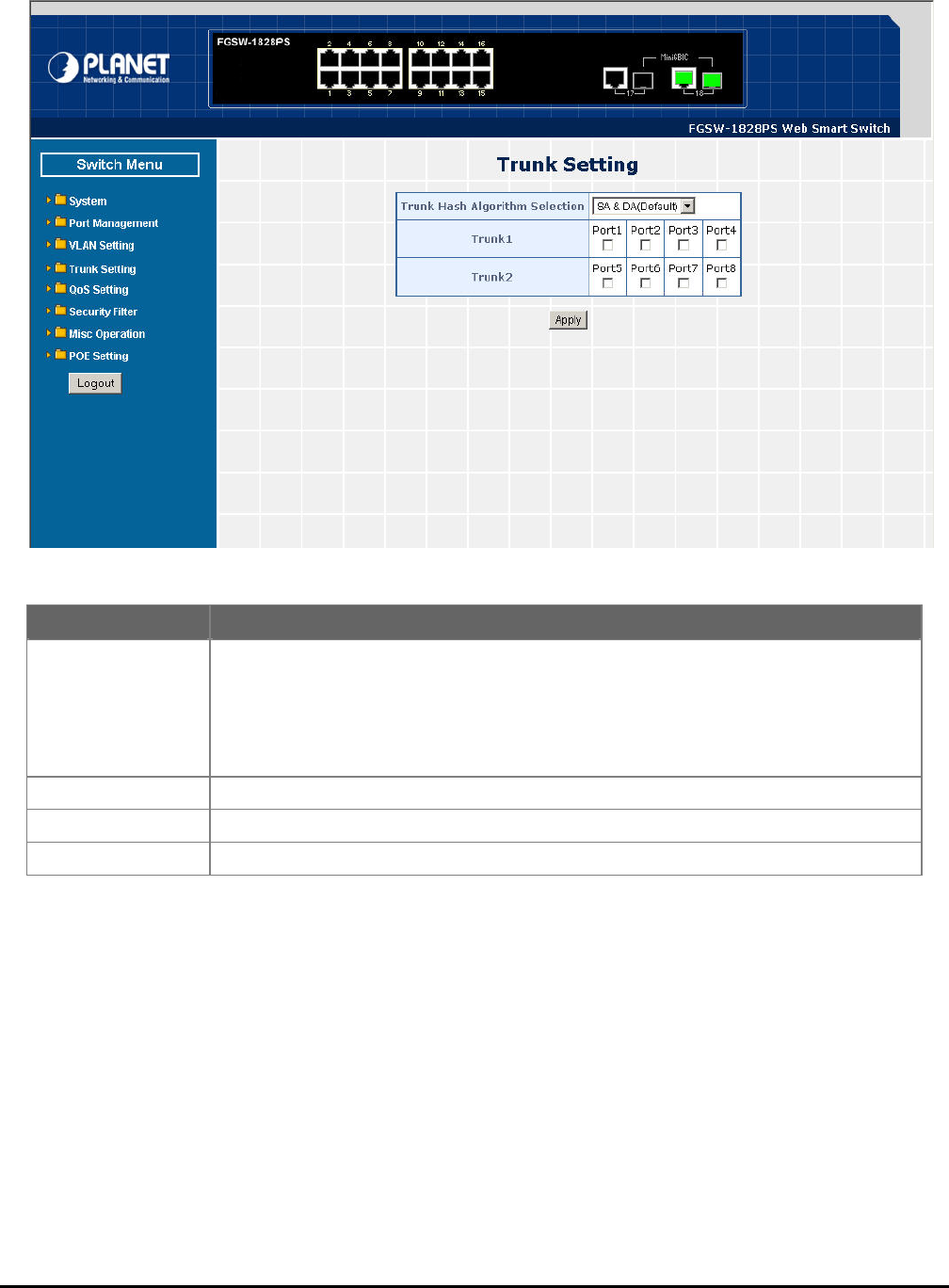
This function allows to con
member ports. Also provid
figuring the trunk function. It provides up to two trunk groups and each trunk group provides 4
e four various Trunk Hash Algorithm policies for selection. The screen in Figure 4-42 appears
and table 4-16 description the Trunk Setting objects of Web Smart PoE Switch.
Figure 4-42 Trunk Setting Web Page Screen
Table 4-16 Descriptions of the Trunk Setting Screen Objects
Object Description
Trunk Hash Algorithm
selection Provide four various Trunk Hash Algorithm polices, the available options are shown as below:
SA & DA(Default)
Port ID
SA
DA
Default mode is SA & DA.
Trunk1 Indicate the Trunk Member Port 1,2,3,4 of Web Smart PoE Switch.
Trunk2 Indicate the Trunk Member Port 5,6,7,8 of Web Smart PoE Switch.
Apply Press this button for save current configuration of Web Smart PoE Switch.
- 50 -
4-6 QoS Setting
Quality of Service (QoS) is an advanced traffic prioritization feature that allows you to establish control over network traffic.
QoS enables you to assign various grades of network service to different types of traffic, such as multi-media, video,
protocol-specific, time critical, and file-backup traffic.
QoS reduces bandwidth limitations, delay, loss, and jitter. It also provides increased reliability for delivery of your data and
allows you to prioritize certain applications across your network. You can define exactly how you want the switch to treat
selected applications and types of traffic.
You can use QoS on your system to:
。 Control a wide variety of network traffic by:
。 Classifying traffic based on packet attributes.
。 Assigning priorities to traffic (for example, to set higher priorities to time-critical or business-critical applications).
。 Applying security policy through traffic filtering.
。 Provide predictable throughput for multimedia applications such as video conferencing or voice over IP by minimizing
delay and jitter.
。 Improve performance for specific types of traffic and preserve performance as the amount of traffic grows.
。 Reduce the need to constantly add bandwidth to the network.
。 Manage network congestion.
This function provides QoS Setting of Web Smart PoE Switch; the screen in Figure 4-43 appears and table 4-17 descrip-
tions the QoS Setting of Web Smart PoE Switch.
Figure 4-43 QoS Setting Web Page Screen
Table 4-17 Descriptions of the QoS Setting Screen Objects
Object Description
Priority Mode Provide three different Priority polices on Web Smart PoE Switch. Explained in section 4.6.1.
Class of Service Con-
tion Provide three different polices on each port of Web Smart PoE Switch. Explained in section
4.6.2.
figura
T
QCP/UDP Port Based
oS Allow to define various QoS mode on TCP / UDP port. Explained in section 4.6.3.

- 51 -
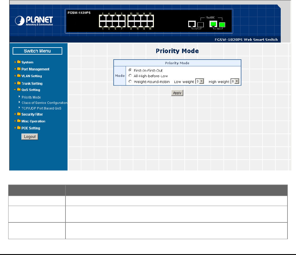
4.6.1 Priority Mode
This section introduces detail information of Priority Mode of Web Smart PoE Switch; the screen in Figure 4-44 appears
and table 4-18 descriptions the Priority Mode of Web Smart PoE Switch.
Figure 4-44 Priority Mode Web Page Screen
Table 4-18 Descriptions of the Priority Mode Screen Objects
Object Description
Priority Mode Provide three different Priority polices on Web Smart PoE Switch, the available options are
shown as below:
Fist-In-First-Out
All-High-Before-Low
Weight-Round-Robin= Low weight (0-7 range) : High weight (0-7 range)
Default mode is First-In-First-Out.
Apply Press this button for save current configuration of Web Smart PoE Switch.
- 52 -
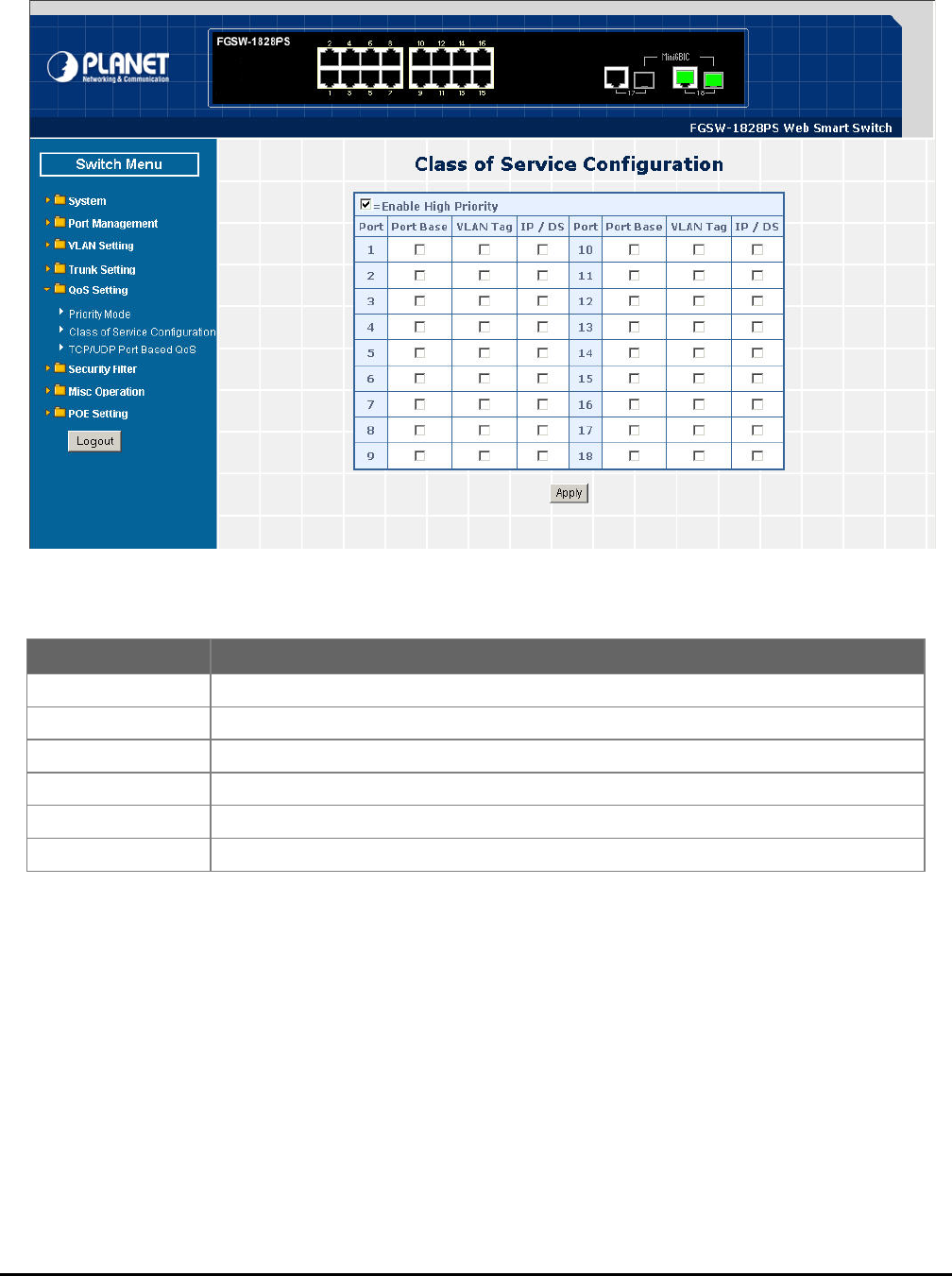
4.6.2 Class of Service Configuration
on of Web Smart PoE Switch.
This section introduces detail information of Class of Service Configuration of Web Smart PoE Switch; the screen in Figure
4-45 appears and table 4-19 descriptions the Class of Service Configurati
Figure 4-45 Class of Service Configuration Web Page Screen
Table 4-19 Descriptions of the Class of Service Configuration Screen Objects
Object Description
Enable High Priority enable the High Priority function. Default mode is Enable. Allow to disable or
Port Indicate port 1 to port 16 (FNSW-1608PS), port 1 to port 18 (FGSW-1828PS).
Port Base y based on Port Base policy. Define per port Class of Service polic
VLAN Tag Define per port Class of Service policy based on VLAN Tag priority policy.
IP /DS Define per port Class of Service policy based on IP / DS policy.
Apply Press this button for save current configuration of Web Smart PoE Switch.
- 53 -
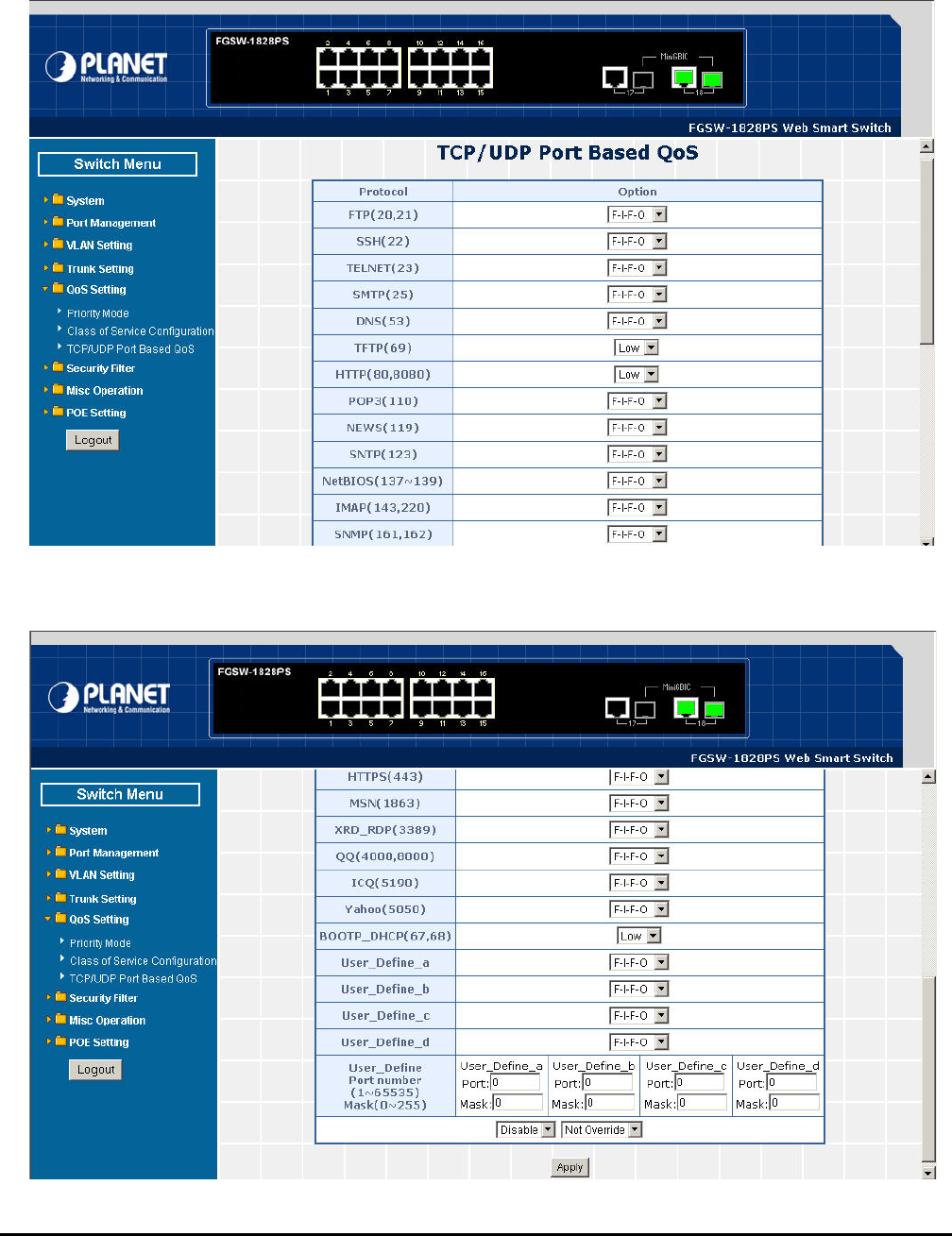
4.6.3 TCP / UDP Port Based QoS
This section introduces detail information of TCP / UDP Port Based QoS Configuration of Web Smart PoE Switch; the
screen in Figure 4-46 & 4-47 appears and table 4-20 descriptions the TCP / UDP Port Based QoS Configuration of Web
Smart PoE Switch.
Figure 4-46 TCP / UDP Port Based QoS Configuration Web Page Screen
Figure 4-47 TCP / UDP Port Based QoS Configuration Web Page Screen

- 54 -
Table 4-20 Descriptions of the TCP / UDP Port Based QoS Configuration Screen Objects
Object Description
Protocol Display different Protocol for define the QoS policy in option
FTP(20,21) Provide F-I-F-O, Discard, Low, High options.
SSH(22) Provide F-I-F-O, Discard, Low, High options.
TELNET(23) Provide F-I-F-O, Discard, Low, High options.
SMTP(25) Provide F-I-F-O, Discard, Low, High options.
DNS(53) Provide F-I-F-O, Discard, Low, High options.
TFTP(69) Provide Low, High options.
HTTP(80,8080) Provide Low, High options.
POP3(110) Provide F-I-F-O, Discard, Low, High options.
NEWS(119) Provide F-I-F-O, Discard, Low, High options.
SNTP(123) Provide F-I-F-O, Discard, Low, High options.
NetBIOS(137~139) Provide F-I-F-O, Discard, Low, High options.
IMAP(143,220) Provide F-I-F-O, Discard, Low, High options.
SNMP(161,162) Provide F-I-F-O, Discard, Low, High options.
HTTPS(443) Provide F-I-F-O, Discard, Low, High options.
MSN(1863) Provide F-I-F-O, Discard, Low, High options.
XRD_RDP(3389) Provide F-I-F-O, Discard, Low, High options.
QQ(4000,8000) Provide F-I-F-O, Discard, Low, High options.
ICQ(5190) Provide F-I-F-O, Discard, Low, High options.
Yahoo(5050) Provide F-I-F-O, Discard, Low, High options.
BOOTP_DHCP(67,68) Provide Low, High options.
User_Define_a Provide F-I-F-O, Discard, Low, High options.
User_Define_b Provide F-I-F-O, Discard, Low, High options.
User_Define_c Provide F-I-F-O, Discard, Low, High options.
User_Define_d Provide F-I-F-O, Discard, Low, High options.
User_Define
Port number
(1~65535)
Mask(0~255)
Allow to define 4 protocol port numbers, such as Port and Mask. The available options are
shown as below:
User_Define_a
User_Define_b
User_Define_c
User_Define_d
Disable Allow to choose “Disable” or “Enable” options. Default mode is Disable.
Not Override Allow to choose “Override” or “Not Override” options. Default mode is Not Override .
Apply Press this button for save current configuration of Web Smart PoE Switch.

- 55 -
4-7 Security Filter
ovides Security Filter of Web Smart PoE Switch; the screen in Figure 4-48 appears and table 4-21 de-
e Security F
This function pr
scriptions th ilter of Web Smart PoE Switch.
Figure 4-48 Security Filter Web Page Screen
eb Page Screen Objects
Table 4-21 Descriptions of the Security Filter W
Object Description
MAC Address Filter Web Smart PoE Switch. Explained in section Allow define three MAC Address on per port of
4.7.1.
TCP/UDP Filter Allow define the filter policy of TCP / UDP flow on Web Smart PoE Switch. Explained in section
4.7.2.
- 56 -
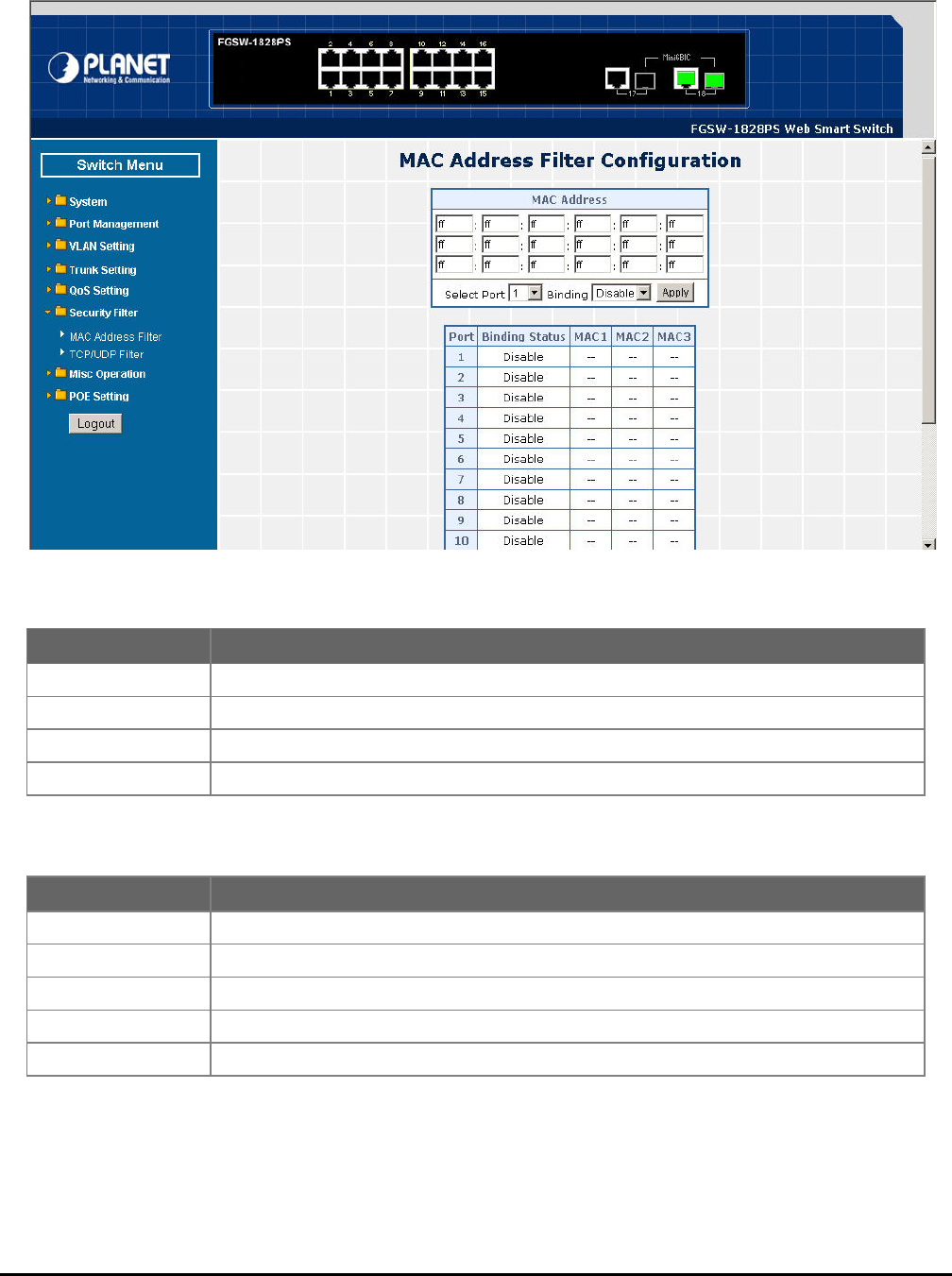
4.7.1 MAC Address Filter
ress Filter of Web Smart PoE Switch.
This section introduces detail information of MAC Address Filter of Web Smart PoE Switch; the screen in Figure 4-49
appears and table 4-22 & 4-23 descriptions the MAC Add
Figure 4-49 MAC Address Filter Web Page Screen
Table 4-22 Descriptions of the MAC Address Filter Screen Objects
Table 4-23 Descriptions of the MAC Address Filter Screen Objects
Object Description
MAC Address Allow to input three MAC Address on per port of Web Smart PoE Switch.
Select Port Allow to select port 1 to port 16 (FNSW-1608PS), port 1 to port 18 (FGSW-1828PS).
Binding Allow to itch. Disable or Enable the binding function on each port of Web Smart PoE Sw
Apply Press this button for save current configuration of Web Smart PoE Switch.
Object Description
Port Indicate port 1 to port 16 (FNSW-1608PS), port 1 to port 18 (FGSW-1828PS).
Binding Status Display Binding Status from each port of Web Smart PoE Switch.
MAC 1 Display first assigns MAC Address on each port of Web Smart PoE Switch.
MAC 2 Display second assigns MAC Address on each port of Web Smart PoE Switch.
MAC 3 Display third assigns MAC Address on each port of Web Smart PoE Switch.

- 57 -
4.7.2 TCP / UDP Filter
This section introduces detail information of TCP / UDP Filter of Web Smart PoE Switch; the screen in Figure 4-50 appea
and table 4-24 descriptions the TCP / UDP Filter Configuration of Web Smart PoE Switch.
rs
Figure 4-50 TCP / UDP Filter Web Page Screen

- 58 -
Table 4-24 Descriptions of the TCP / UDP Filter Configuration Screen Objects
Object Description
Function Enable Allow to Disable or Enable the TCP / UDP Filter function. Default mode is Disable.
Port Filtering Rule Allow to Forward or Block the Port Filtering Rule. Default mode is Block.
Protocol Display different Protocol for define the TCP / UDP Filter policy.
FTP(20,21)
SSH(22)
TELNET(23)
SMTP(25)
DNS(53)
TFTP(69)
HTTP(80,8080)
POP3(110)
NEWS(119)
SNTP(123)
NetBIOS(137~139)
IMAP(143,220)
SNMP(161,162)
HTTPS(443)
MSN(1863)
XRD_RDP(3389)
QQ(4000,8000)
ICQ(5190)
Yahoo(5050)
BOOTP_DHCP(67,68)
User_Define_a
User_Define_b
User_Define_c
User_Define_d
Allow to choose list protocol for filtering
Secure Egress Port Indicate port 1 to port 16 (FNSW-1608PS), port 1 to port 18 (FGSW-1828PS).Click specific port
for filtering.
Apply Press this button for save current configuration of Web Smart PoE Switch.

- 59 -
4-8 Misc Operation
This function provides M 4-25 de-
itch.
isc Operation of Web Smart PoE Switch; the screen in Figure 4-51 appears and table
eb Smart PoE Swscriptions the Misc Operation of W
Figure 4-51 Misc Operation Web Page Screen
Table 4-25 Descriptions of the Misc Operation Web Page Screen Objects
Object Description
Output Queue Aging Time Allow define the Output Queue Aging Time of Web Smart PoE Switch, the available op-
tions are Disable, 200ms, 400ms, 600ms and 800ms. Default mode is Disable.
VLAN Striding Allow Disable or Enable the VLAN Striding function of Web Smart PoE Switch. Default
mode is Disable.
IGMP Snooping V1 & V2 Allow Disable or Enable the IGMP Snooping V1 & V2 function of Web Smart PoE Switch.
Default mode is Disable.
Apply Press this button for save current configuration of Web Smart PoE Switch.
- 60 -
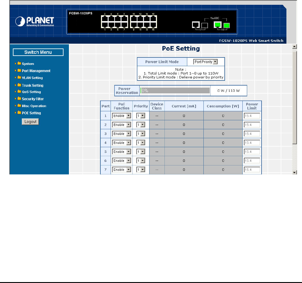
4-9 POE Setting
Power Management:
In a power over Ethernet system, operating power is applied from a power source (PSU-power supply unit) over the LAN
infrastructure to powered devices (PDs), which are connected to ports. Under some conditions, the total output power
required by PDs can exceed the maximum available power provided by the PSU. The system may a prior be planed with a
PSU capable of supplying less power than the total potential power consumption of all the PoE ports in the system. In order
to maintain the majority of ports active, power management is implemented.
The PSU input power consumption is monitored by measuring voltage and current .The input power consumption is equal
to the system’s aggregated power consumption .The power management concept allows all ports to be active and acti-
vates additional ports, as long as the aggregated power of the system is lower than the power level at which additional PDs
cannot be connected .When this value is exceeded, ports will be deactivated, according to user-defined priorities. The
power budget is managed according to the following user-definable parameters: maximum available power, ports priority,
maximum allowable power per port.
This function provides PoE setting of Web Smart PoE Switch; the screen in Figure 4-52 appears and table 4-26 descrip-
tions the Misc Operation of Web Smart PoE Switch.
Figure 4-52 POE Setting Web Page Screen

- 61 -
Table 4-26 Descriptions of the POE Setting Web Page Screen Objects
Object Description
Power limit mode Allow to configure power limit mode of Web Smart PoE Switch. It can choose :
Port Priority Deliver PoE power by port priority setting
Total Limit. Set limit value of the total POE port provided power to the PDs.
For Web Smart PoE Switch, the total PoE power reservation from Port-1~8 is up to 110 watts
Power reservation Show the total watts usage of Web Smart PoE Switch.
Port Indicate the PoE port from 1 to 8.
PoE Function Allow disable or enable the PoE function.
Priority Allow assign port priority for the POE power management
It can choose the “port priority”, value range from “1~4” and the High priority is “1”.
Device class Class 0 is the default for PDs. However, to improve power management at the PSE, the PD may
The PD is classified based on power. The classification of the PD is the maximum power that the
PD will draw across all input voltages and operational modes. A PD shall return Class 0 to 3 in
accordance with the maximum power draw as specified by Table 4.1.
opt to provide a signature for Class 1 to 3.
Current(mA) It shows the PoE device current Amp.
Consumption [W] It shows the PoE device current watt.
Power Limit It can limit the port PoE supply watts.
Per port maximum value must less 15.4, total ports values must less than the Power Reserva-
tion value.
Once power overload detected, the port will auto shut down and keep on detection mode until
PD’s power consumption lower than the power limit value.
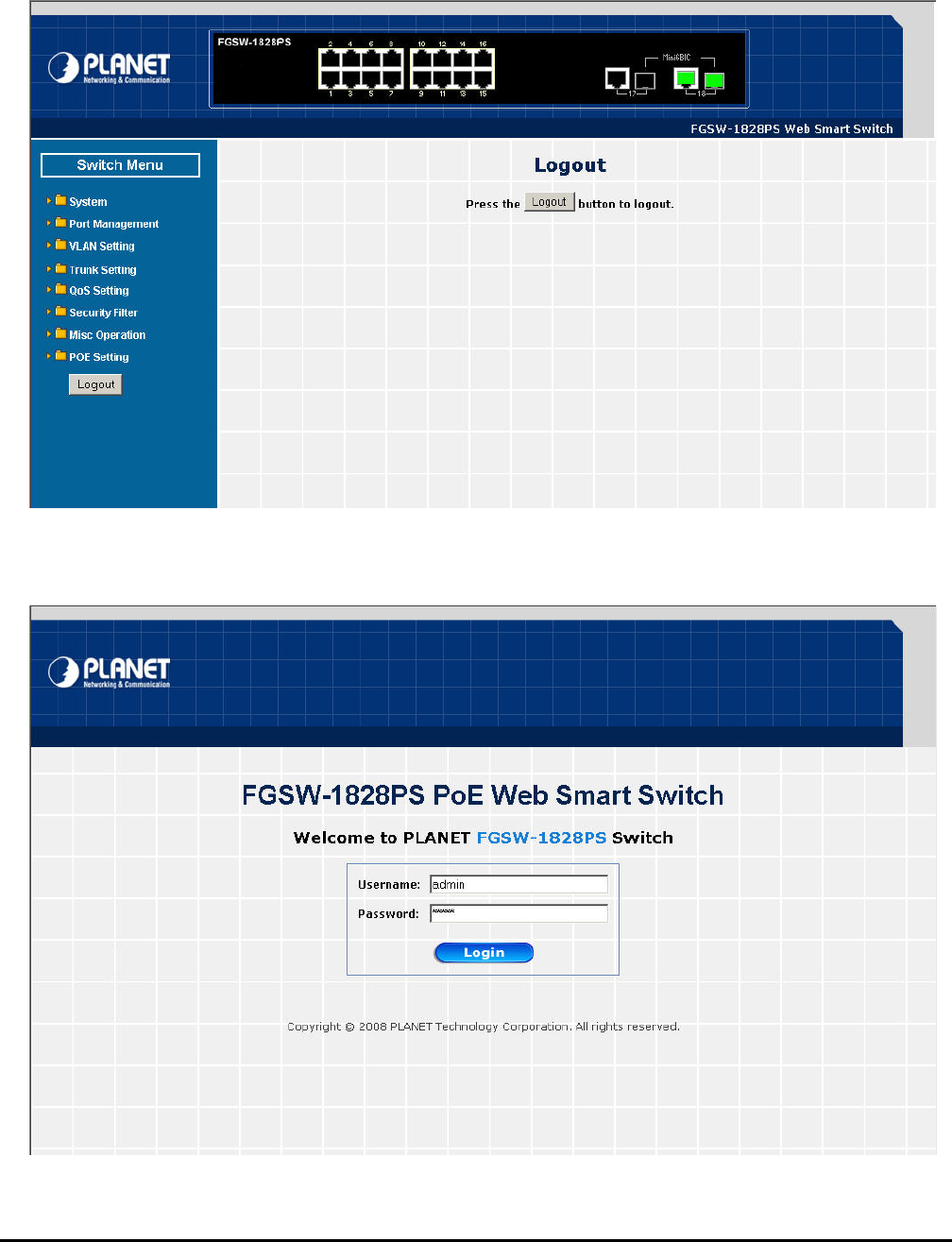
- 62 -
4-10 Logout
Web lowing screen
appears in Figure 4-53 & 4-54 eb Screen appears. Please
re-login the Web Smart PoE Sw
This section provide logout function on Web Smart PoE Switch, after choose this function and the fol
. Please press “Logout” button to take effect and Login W
itch for further management.
Figure 4-53 Logout Web Page Screen
Figure 4-54 Login Web Page Screen

- 63 -
5. SWITCH OPERATION
The Switch is implemented with an address table. This address table composed of many entries. Each entry is used to
store the address information of some node in network, including MAC address, port no, etc. This information comes
from the learning process of Ethernet Switch.
5.2 Learning
When one packet comes in from any port. The Switch will record the source address, port no. And the other related
information in address table. This information will be used to decide either forwarding or filtering for future packets.
5.3 Forwarding & Filtering
When one packet comes from some port of the Ethernet Switching, it will also check the destination address besides
the source address learning. The Ethernet Switching will lookup the address-table for the destination address. If not
found, this packet will be forwarded to all the other ports except the port which this packet comes in. And these ports
will transmit this packet to the network it connected. If found, and the destination address is located at different port
from this packet comes in, the Ethernet Switching will forward this packet to the port where this destination address is
located according to the information from address table. But, if the destination address is located at the same port with
this packet comes in, then this packet will be filtered. Thereby increasing the network throughput and availability.
5.4 Store-and-Forward
Store-and-Forward is one type of packet-forwarding techniques. A Store-and Forward Ethernet Switching stores the
incoming frame in an internal buffer, do the complete error checking before transmission. Therefore, no error packets
occurrence, it is the best choice when a network needs efficiency and stability.
The Ethernet Switch scans the destination address from the packet-header, searches the routing table provided for
the incoming port and forwards the packet, only if required. The fast forwarding makes the switch attractive for
connecting servers directly to the network, thereby increasing throughput and availability. However, the switch is most
commonly used to segment existing hubs, which nearly always improves overall performance. An Ethernet Switching
can be easily configured in any Ethernet network environment to significantly boost bandwidth using conventional
cabling and adapters.
Due to the learning function of the Ethernet switching, the source address and corresponding port number of each
incoming and outgoing packet are stored in a routing table. This information is subsequently used to filter packets
whose destination address is on the same segment as the source address. This confines network traffic to its re-
spective domain, reducing the overall load on the network.
The Switch performs "Store and forward" therefore, no error packets occur. More reliably, it reduces the
re-transmission rate. No packet loss will occur.
5.5 Auto-Negotiation
The STP ports on the Switch have built-in "Auto-negotiation". This technology automatically sets the best possible
bandwidth when a connection is established with another network device (usually at Power On or Reset). This is done
by detect the modes and speeds at the second of both device is connected and capable of, both 10Base-T and
100Base-TX devices can connect with the port in either Half- or Full-Duplex mode. 1000Base-T can be only con-
nected in Full-duplex mode.
5.1 Address Table
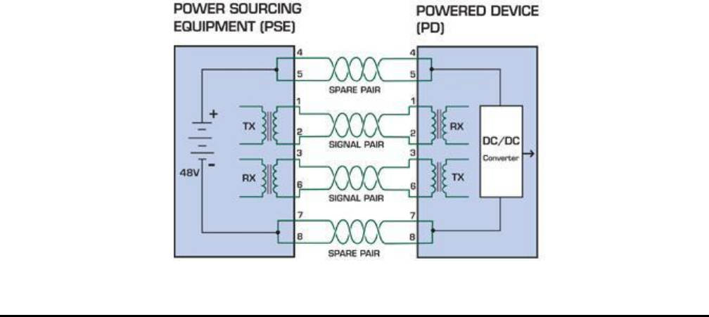
- 64 -
6. POWER OVER
Based on the global standard IEEE 802.3af, PoE is a technology
netw
carri
and Wireless Networking, can help enterprises improve productivity. It minimizes wires that must be used to install the
netw rk for offering lower cost, and less power failures.
alled Data Terminal equipment (DTE) power via Media dependent interface (MDI) is an international
stan
side
n legacy switch and the powered device. Mid-Span is tap the unused wire pairs 4/5
PoE
The specification of PoE typically requires two devices: the Powered Source Equipment (PSE) and the Powered Device
an or a Mid-Span, while the PD is a PoE-enabled terminal, such as IP Phones, Wireless
LAN, etc. Power can be delivered over data pairs or spare pairs of standard CAT-5 cabling.
How
A sta
spec
The
the p
to be used).
ETHERNET OVERVIEW
What is PoE?
for wired Ethernet, the most widely installed local area
ork technology adopted today. PoE allows the electrical power necessary for the operation of each end-device to be
ed by data cables rather than by separate power cords. New network applications, such as IP Cameras, VoIP Phones,
o
IEEE802.3af also c
dard to define the transmission for power over Ethernet. The 802.3af is delivering 48V power over RJ-45 wiring. Be-
s 802.3af also define two types of source equipment: Mid-Span and End-Span.
Mid-Span
Mid-Span device is placed betwee
and 7/8 to carry power, the other four is for data transmit.
End-Span
End-Span device is direct connecting with power device. End-Span could also tap the wire 1/2 and 3/6.
System Architecture
(PD). The PSE is either an End-Sp
Power is Transferred Through the Cable
ndard CAT5 Ethernet cable has four twisted pairs, but only two of these are used for 10BASE-T and 100BASE-T. The
ification allows two options for using these cables for power, shown in Figure 2 and Figure 3:
spare pairs are used. Figure 2 shows the pair on pins 4 and 5 connected together and forming the positive supply, and
air on pins 7 and 8 connected and forming the negative supply. (In fact, a late change to the spec allows either polarity
Figure 1 - Power Supplied over the Spare Pins
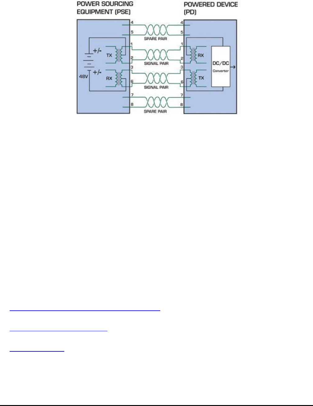
- 65 -
The data pairs are used. Since Ethernet pairs are tra
center tap of the isolation transformer without upsetti
and the pair on pins 1 and 2 can be of either polarity.
nsformer coupled at each end, it is possible to apply DC power to the
ng the data transfer. In this mode of operation the pair on pins 3 and 6
Figure 2 - Power Supplied over the Data Pins
When to install PoE?
Consider the following scenarios:
• You're planning to install the latest VoIP Phone system to minimize cabling building costs when your company moves into
new offices next month.
• The company staff has been clamoring for a wireless access point in the picnic area behind the building so they can work
power to the outside is not affordable.
References:
IEEE Std 802.3af-2003 (Amendment to IEEE Std 802.3-2002, including IEEE Std 802.3ae-2002), 2003 Page(s):0_1-121
White Paper on Power over Ethernet (IEEE802.3af)
http://www.poweroverethernet.com/articles.php?article_id=52
on their laptops through lunch, but the cost of electrical
• Management asks for IP Surveillance Cameras and business access systems throughout the facility, but they would
rather avoid another electrician's payment.
Microsemi /PowerDsine
http://www.microsemi.com/PowerDsine/
Linear Tech
http://www.linear.com/

- 66 -
7. THE POE PROVISION PROCESS
While adding PoE support to networked devices is relatively painless, it should be realized that power cannot simply be
transferred over existing CAT-5 cables. Without proper preparation, doing so may result in damage to devices that are not
designed to support provision of power over their network interfaces.
The PSE is the manager of the PoE process. In the beginning, only small voltage level is induced on the port's output, till a
valid PD is detected during the Detection period. The PSE may choose to perform classification, to estimate the amount of
power to be consumed by this PD. After a time-controlled start-up, the PSE begins supplying the 48 VDC level to the PD, till
it is physically or electrically disconnected. Upon disconnection, voltage and power shut down.
Since the PSE is responsible for the PoE process timing, it is the one generating the probing signals prior to operating the
PD and monitoring the various scenarios that may occur during operation.
All probing is done using voltage induction and current measurement in return.
Stages of powering up a PoE link
Stage Action Volts speci-
fied
per 802.3af
Volts man-
aged
by chipset
Detection Measure whether powered device has the correct
signature resistance of 15–33 kΩ 2.7-10.0 1.8–10.0
Classification Measure which power level class the resistor indi-
cates 14.5-20.5 12.5–25.0
Startup Where the powered device will startup >42 >38
Normal operation Supply power to device 36-57 25.0–60.0
7.1 Line Detection
Before power is applied, safety dictates that it must first be ensured that a valid PD is connected to the PSE's output. This
and involves the PSE seeking a specific, 25 KΩ signature resistor. Detection of
is signature indicates that a valid PD is connected, and that provision of power to the device may commence.
he signature resistor lies in the PD's PoE front-end, isolated from the rest of the the PD's circuitries till detection is certi-
ed.
ation, to determine the maximal power a PD is to consume.
.5 VDC, limited to 100 mA, for a period of 10 to 75 ms responded by a certain current con-
class.
igned to one of 5 classes: 0 (default class) indicates that full 15.4 watts should be provided, 1-3 indicate
levels and 4 is reserved for future use. PDs that do not support classification are assigned to class
0. Special care must be employed in the definition of class thresholds, as classification may be affected by cable losses.
Classifying a PD according to its power consumption may assist a PoE system in optimizing its power distribution. Such a
system typically suffers from lack of power resources, so that efficient power management based on classification results
may reduce total system costs.
process is referred to as "line detection",
th
T
fi
7.2 Classification
Once a PD is detected, the PSE may optionally perform classific
The PSE induces 15.5-20
sumption by the PD, indicating its power
The PD is ass
various required power

- 67 -
7.3 Start-up
h frequencies) would introduce noise on the data
uring normal operation, the PSE provides 44-57 VDC, able to support a minimum of 15.4 watts power.
The IEEE 802.3af standard defines handling of overload conditions. In the event of an dra
p el than the allo Watts), or an outright short circuit caused by a failure in cabling or in the PD, the PSE
must shut down power within 50 to 75 milliseconds, while limiting current drain during t otec
in Immediat om fl .
7 con on Scenarios
T 02.3af stand net be disconnect ely (i.e. power needs be shut
d ction of a PD from an active port)
hen a PD is disconnected, there is a danger that it will be replaced by a non-PoE-ready device while power is still on.
Imagine disconnecting a powered IP phone utilizing 48 VDC, then inadvertently plugging the powered Ethernet cable into a
r. What’s sure to follow is not a pretty picture.
ent of current. Naturally, a disconnected PD stops consuming current, which
an be inspected by the PSE. The PSE must therefore disconnect power within 300 to 400 ms from the current flow stop.
s important to prevent shutdown due to random fluctuations.
nals
port (disconnected PD).
d
Once line detection and optional classification stages are completed, the PSE must switch from low voltage to its full
voltage capacity (44-57 Volts) over a minimal amount of time (above 15 microseconds).
A gradual startup is required, as a sudden rise in voltage (reaching hig
lines.
Once provision of power is initiated, it is common for inrush current to be experienced at the PSE port, due to the PD’s input
capacitance. A PD must be designed to cease inrush current consumption (of over 350 mA) within 50 ms of power provi-
sion startup.
7.4 Operation
D
Power Overloads
overload (a PD wing a higher
ower lev wed 12.95
his period to pr t the cabling
frastructure. e voltage drop is avoided to prevent shutdown due to rand uctuations
.5 Power Dis necti
he IEEE 8 ard requires that devices powered over Ether ed saf
own within a short period of time following disconne .
W
non-PoE notebook compute
The standard defines two means of disconnection, DC Disconnect and AC Disconnect, both of which provide the same
functionality - the PSE shutdowns power to a disconnected port within 300 to 400ms. The upper boundary is a physical
human limit for disconnecting one PD and reconnecting another.
DC Disconnect
DC Disconnect detection involves measurem
c
The lower time boundary i
AC Disconnect
This method is based on the fact that when a valid PD is connected to a port, the AC impedance measured on its termi
is significantly lower than in the case of an open
AC Disconnect detection involves the induction of low AC signal in addition to the 48 VDC operating voltage. The returne
AC signal amplitude is monitored by the PSE at the port terminals. During normal operation, the PD's relatively low im-
pedance lowers the returned AC signal while a sudden disconnection of this PD will cause a surge to the full AC signal level
and will indicate PD disconnection.

- 68 -
8. TROUBLESHOOTING
net This chapter contains information to help you solve issues. If the Switch is not functioning properly, make sure the Ether
Switch was set up according to instructions in this manual.
The Link LED is not lit
heck the cable connection and remove duplex mode of the Switch.
Solution:
C
Some stations cannot talk to other stations located on the other port
Solution:
Please check the VLAN, port trunking function that may introduce this kind of problem.
Performance is bad
Solution:
Check the full duplex status of the Ethernet Switch. If the Ethernet Switch is set to full duplex and the partner is set to
the performance will be poor. half duplex, then
100Base-TX port link LED is lit, but the traffic is irregular
Solution:
Check that the
change duplex
attached device is not set to dedicate full duplex. Some devices use a physical or software switch to
modes. Auto-negotiation may not recognize this type of full-duplex setting.
Why the Switch doesn’t connect to the network
Solution:
Check the LNK/ACT LED on the switch Try another port on the Switch Make sure the cable is installed properly Mak
sure the cable is the right type Turn off the power. After a while, turn on power again.
e
Why I connect my PoE device to FNSW-1608PS / FGSW-1828PS and it cannot power on?
onnection from FNSW-1608PS / FGSW-1828PS (port 1 to
be an 8-wire UTP, Category 5 or above, EIA568 cable
Solution:
1. Please check the cable type of the c
port 8) to the other end. The cable should
within 100 meters. A cable with only 4-wire, short loop or over 100 meters, all will affect the
power supply.
2. Please check and assure the device that fully complied with IEEE 802.3af standard.
How to deal forgotten password situation of FNSW-1608PS / F
Solution: GSW-1828PSS?
Please press Reset button at front panel for 5 seconds then the Web Smart PoE Switch will reset to
factory default mode(username and password: admin)

- 69 -
APPENDIX A NETW
T
ORKING CONNECTION
A.1 Switch‘s RJ-45 Pin Assignments
1000Mbps, 1000Base
Contact MDI MDI-X
1 BI_DA+ BI_DB+
2 BI_DA- BI_DB-
3 BI_DB+ BI_DA+
4 BI_DC+ BI_DD+
5 BI_DC- BI_DD-
6 BI_DB- BI_DA-
7 BI_DD+ BI_DC+
8 BI_DD- BI_DC-
10/100Mbps, 10/100Base-TX
RJ-45 Connector pin assignment
Contact
MDI
Media Dependant
Interface
MDI-X
Media Dependant
Interface -Cross
1 Tx + (transmit) Rx + (receive)
2 Tx - (transmit) Rx - (receive)
3 Rx + (receive) Tx + (transmit)
4, 5 Not used
6 Rx - (receive) Tx - (transmit)
7, 8 Not used
A.2 RJ-45 cable pin assignment
213 6
1
2
3
6
2 1
3 6
The standard RJ-45 receptacle/connector
- 70 -
There are 8 wires on a standard UTP/STP ca
and color of straight cable and crossover cable
ble and each wire is color-coded. The following shows the pin allocation
connection:
Straight Cable SIDE 1 SIDE2
SIDE 1
12345678
12345678
SIDE 2
1 = White / Orange
2 = Orange
3 = White / Green
4 = Blue
5 = White / Blue
6 = Green
7 = White / Brown
8 = Brown
1 = White / Orange
2 = Orange
3 = White / Green
4 = Blue
5 = White / Blue
6 = Green
7 = White / Brown
8 = Brown
Straight Cable SIDE 1 SIDE2
SIDE 1
12345678
12345678
SIDE 2
1 = White / Orange
2 = Orange
3 = White / Green
4 = Blue
5 = White / Blue
6 = Green
7 = White / Brown
8 = Brown
1 = White / Orange
2 = Green
3 = White / Orange
4 = Blue
5 = White / Blue
6 = Orange
7 = White / Brown
8 = Brown
A-1: Stra nd Crossover Cable
Please make sure your connected cables are with same e picture before deploying the
cables into r network.
Figure ight-Through a
pin assignment and color as abov
you
2080-A31120-006

PLANET TECHNOLOGY CORPORATION
e-mail: sales@planet.com.tw http://www.planet.com.tw
EC Declaration of Conformity
For the following equipment:
*Type of Product: 16-Port 10/100Base-TX + 2G TP/SFP Combo Web Smart PoE Switch
*Model Number: FGSW-1828PS
* Produced by:
Manufacturer‘s Name : Planet Technology Corp.
Manufacturer‘s Address: 11F, No 96, Min Chuan Road
Hsin Tien, Taipei, Taiwan , R. O.C.
is herewith confirmed to comply with the requirements set out in the Council Directive on the
Approximation of the Laws of the Member States relating to Electromagnetic Compatibility
Directive on (89/336/EEC,92/31/EEC,93/68/EEC).
For the evaluation regarding the EMC, the following standards were applied:
Emission EN 50081-1 (1992)
Conducted / Radiated EN 55022 (1998)
Harmonic EN 61000-3-2 (1995)
Flicker EN 61000-3-3 (1995)
Immunity EN 55024 (1998)
ESD EN 61000-4-2 (1995)
RS EN 61000-4-3 (1996)
EFT/ Burst EN 61000-4-4 (1995)
Surge EN 61000-4-5 (1995)
CS EN 61000-4-6 (1996)
Voltage Disp EN 61000-4-11 (1994)
Responsible for marking this declaration if the:
⌧ Manufacturer Authorized representative established within the EU
Authorized representative established within the EU (if applicable):
Company Name: Planet Technology Corp.
Company Address: 11F, No.96, Min Chuan Road, Hsin Tien, Taipei, Taiwan, R.O.C
Person responsible for making this declaration
Name, Surname Kent Kang
Position / Title : Product Manager
Taiwan 10th, JUNE, 2008
Place Date Legal Signature
11F, No. 96, Min Chuan Road, Hsin Tien, Taipei, Taiwan, R.O.C. Tel:886-2-2219-9518 Fax:886-2-2219-9528

PLANET TECHNOLOGY CORPORATION
e-mail: sales@planet.com.tw http://www.planet.com.tw
11F, No. 96, Min Chuan Road, Hsin Tien, Taipei, Taiwan, R.O.C. Tel:886-2-2219-9518 Fax:886-2-2219-9528
EC Declaration of Conformity
For the following equipment:
*Type of Product : 16-Port 10/100Mbps / 8-Port PoE Web Smart Ethernet Switch
*Model Number : FNSW-1608PS
* Produced by:
Manufacturer‘s Name : Planet Technology Corp.
Manufacturer‘s Address: 11F, No 96, Min Chuan Road
Hsin Tien, Taipei, Taiwan , R. O.C.
is herewith confirmed to comply with the requirements set out in the Council Directive on the
Approximation of the Laws of the Member States relating to Electromagnetic Compatibility
Directive on (89/336/EEC,92/31/EEC,93/68/EEC).
For the evaluation regarding the EMC, the following standards were applied:
Emission EN 55022 (1998 Class B)
Harmonic EN 61000-3-2 (2000)
Flicker EN 61000-3-3 (1995)
Immunity EN 55024 (1998)
ESD EN 61000-4-2 (1995)
RS EN 61000-4-3 (1995)
EFT/ Burst EN 61000-4-4 (1995)
Surge EN 61000-4-5 (1995)
CS EN 61000-4-6 (1996)
Magnetic Field EN 61000-4-8 (1993)
Voltage Disp EN 61000-4-11 (1994)
Responsible for marking this declaration if the:
⌧ Manufacturer Authorized representative established within the EU
Authorized representative established within the EU (if applicable):
Company Name: Planet Technology Corp.
Company Address: 11F, No.96, Min Chuan Road, Hsin Tien, Taipei, Taiwan, R.O.C
Person responsible for making this declaration
Name, Surname Kent Kang
Position / Title : Product Manager
Taiwan 10th, JUNE, 2008
Place Date Legal Signature e
