Plantronics CS55YYYY Wireless Telephone Adapter Headset User Manual CT12 User Guide
Plantronics Inc Wireless Telephone Adapter Headset CT12 User Guide
Users Manual
p-3005
p-3005
WELCOME
Thank you for selecting the CS55 Micro™ Wireless Office
Headset System from Plantronics. You have made the right
choice for comfort and versatility.
This system allows your telephone to use a cordless
Plantronics headset through an adapting base. It offers
hands-free convenience and long-range workspace mobility.
With the use of an optional handset lifter, the user can
remotely receive the telephone’s ring alert and can answer
the call by simply pushing the talk button on the headset.
This side of the guide has Important Safety Information
that should be read prior to set up and use of your
system. The quick start part on the other side identifies
the components, has five steps to get you started, and
test the system.
Most telephones will work with little or no adjustments.
This system is not designed to work with phones which
havethe dial pad built into the handset.
The Product Information Booklet in all languages is online
at: http:www.plantronics.com/documentation/
Choose your preferred language and the Plantronics model number “CS55
Micro™” to access complete user documentation including this Quick Start
Guide and the Product Information Booklet which has more on the system’s
operation, adjustments, and troubleshooting.
• Do not locate this product near water, for example,
near a bathtub, or sink, in a wet basement, or near
a swimming pool.
•This product should never be placed near or over a
radiator or heat register. It should not be placed in a
built-in installation unless proper ventilation is provided.
• Do not allow anything to rest on the power cord. Do
not locate this product where persons walking on it will
damage the cord.
• Do not overload outlets and extension cords as this
can result in risk of fireor electric shock.
• Never disassemble or push objects of any kind into the
product since this may short out parts which could result
in a fire or electric shock. Never spill liquid of any kind on
the product.
• Use caution when installing or modifying telephone lines.
•Avoid using telephone equipment during an electrical
storm.
• Keep all product cords and cables away from operating
machinery.
•Do not use this equipment to report a gas leak while
you are in the vicinity of a gas leak.
•Never allow children to play with the headset/adapter–
small parts may be a choking hazard.
• Unplug this product from the wall outlet before cleaning.
Do not use liquid cleaners or aerosol cleaners. Use a
damp cloth for cleaning.
IMPORTANT SAFETY INFORMATION
When using your telephone equipment these
basic safety precautions and warnings should be
followed to reduce the risk of fire, electric shock, and
injury to persons.
• Read and follow all instructions and warnings prior to
using the product. The symbol identifies and alerts
the user to the presence of
important operating, safety, and service instructions.
• This product contains gold-plated nickel, phosphor
bronze and copper. If you experience a skin irritation,
discontinue use and contact Plantronics.
•This product is intended to be powered by a Listed
Class 2 Direct Plug-In Power Unit rated 9VDC at
800mA, Part No. 45561-02, rated at an input voltage
of 120 VAC, 60Hz and an output voltage of 9 VDC at
800mA.
• This product requires AC power in order to operate.
During a power outage, have another telephone
available that is powered only by the telephone line.
BATTERY PRECAUTIONS
Toreduce the risk of fire or injury to persons, read
and followthese instructions.
• Use only the battery pack supplied with this product, part
number 64399-01.
• Do not dispose of battery pack in a fire. The cells may
explode. Check with local codes for disposal instructions.
• Do not open or mutilate battery pack. Released electrolyte
is corrosive and may cause damage to eyes or skin and
may be toxic if swallowed.
• Exercise care in handling the battery pack in order not to
short the battery contacts with conducting materials such
as rings, bracelets, and keys. The battery or conductor
may overheat and cause burns.
• Charge the battery pack in accordance with instructions
supplied with this unit.
•Observeproper orientation between battery pack and
charger contacts.
• Batteries can be swallowed by children and are dangerous
if swallowed. Always store and dispose of batteries where
children can’t reach them.
SAV E THESE INSTRUCTIONS
WARNING
FCC REQUIREMENTS
PART 15
This device complies with Part 15 of the FCC Rules. Operation is subject to the following two conditions:
1. This device may not cause harmful interference, and
2. This device must accept any interference received, including interference that may cause undesired
operation.
This equipment has been tested and found to comply with the limits for a Class B digital device, pursuant
toPart 15 of the FCC Rules. These limits are designed to provide reasonable protection against harmful
interference in a residential installation. This equipment generates, uses, and can radiate radio frequency
energy and, if not installed and used in accordance with the instructions, may cause harmful interference
to radio communications.
However, there is no guarantee that interference will not occur in a particular installation. If this equipment
does cause harmful interference to radio or television reception which can be determined by turning the
radio or television off and on, the user is encouraged to try to correct interference by one or more of the
following measures:
1. Reorient or relocate the receiving antenna.
2. Increase the separation between the equipment and receiver.
3. Connect the equipment into an outlet on another circuit.
4. Consult the dealer or an experienced radio/TV technician for help.
EXPOSURE TO RADIO FREQUENCY RADIA
TION
This device and its antenna must not be co-located or operated in conjunction with any other antenna or
transmitter.To comply with FCC RF exposure requirements, only use the supplied antenna.
The radiated output power of this internal wireless radio is far below the FCC radio frequency exposure
limits. Nevertheless, the wireless radio shall be used as described in the manual.
The internal wireless radio operates within guidelines found in radio frequency safety standards and
recommendations, which reflect the consensus of the scientific community.
Plantronics therefore believes the internal wireless radio is safe for use by consumers. The level of energy
emitted is far less than the electromagnetic energy emitted by wireless devices such as mobile phones.
However, the use of wireless radios may be restricted in some situations or environments, such as aboard
airplanes. If you are unsure of restrictions, you are encouraged to ask for authorization before turning on
the wireless radio.
NOTE: Modifications not expressly approved by Plantronics, Inc. could void the user’s authority to operate
the equipment.
usersshould ensure that it is permissible to be connected to the facilities of the local telecommunications
company. The equipment must also be installed using an acceptable method of connection. The customer
should be aware that compliance with the above conditions may not prevent degradation of service in
some situations. Repairs to certified equipment should be coordinated by a representative designated by
the supplier. Any repairs or alterations made by user to this equipment, or equipment malfunctions, may
givethe telecommunications company cause to request the user disconnect the equipment. Users should
ensure for their own protection that the electrical ground connections of the power utility, telephone lines
and internal metallic water pipe system, if present, are connected together. This precaution may be
particularly important in rural areas.
CAUTION: Usersshould not attempt to make such connection themselves, but should contact the
appropriate electric inspection authority, or electrician, as appropriate.
RSS 210
This digital apparatus does not exceed the Class B limit for radio noise emissions from digital apparatus
set out in the Radio InterferenceRegulations of Industry Canada. Operation is subject to the following two
conditions: 1) this device may not cause interference, and 2) this device must accept any interference,
including interference that may cause undesired operation of the device.
LIMITED WARRANTY
For Plantronics Commercial Products Purchased in the US and Canada
• This warranty covers defects in materials and workmanship of Commercial Products manufactured,
sold or certified by Plantronics which were purchased and used in the United States and Canada.
•This warranty lasts for one year from the date of purchase of the Products.
•This warranty extends to you only if you are the end user with the original purchase receipt.
•Wewill, at our option, repair or replacethe Products that do not conform to the warranty. We may use
functionally equivalent reconditioned/refurbished/ remanufactured/pre-owned or new Products or parts.
• To obtain service in the U.S. contact Plantronics at (800) 544-4660 and in Canada call (800) 540-8363.
If you need additional information, please contact our service centers at the numbers provided.
•THIS IS PLANTRONICS’ COMPLETE WARRANTY FOR THE PRODUCTS.
• This warranty gives you specific legal rights, and you may also have other rights which vary from state
to state or province to province. Please contact your dealer or our service center for the full details of
our limited warranty, including items not covered by this limited warranty.
The Plantronics Technical Assistance Center (TAC) is ready to assist you! Dial (800) 544-4660 x5538
Sunday 5P.M.through Friday, 5P.M.Pacific Time or visit the Support section of our website at
www.plantronics.com. For accessibility information also call the Technical Assistance Center.
PART 68
This equipment complies with Part 68 of the FCC rules and the requirements adopted by ACTA. On the
exterior of this equipment is a label that contains a product identifier in the format US:AAAEQ##TXXXX.
If requested, this information must be provided to your telephone company.
A plug and jack used to connect this equipment to the premises wiring and telephone network must comply
with the applicable FCC Part 68 rules and requirements adopted by ACTA. A compliant telephone cord and
modular plug is provided with this product. It is designed to be connected to a compatible jack that is also
compliant. See installation instructions for details.
The REN is useful todetermine the quantity of devices you may connect to your telephone line. Excessive
RENs on a telephone line may result in the devices not ringing in response to an incoming call. In most, but
not all areas, the sum of the RENs should not exceed five (5.0). To be certain of the number of devices you
may connect to your line, as determined by the REN, contact your local telephone company. For product
approved after July 23, 2001, the REN for this product is part of the product identifier that has the format
US:AAAEQ##TXXXX. The digits represented by ### are the REN without the decimal point. (For example,
03 represents a REN of 0.3.) For earlier producers, the REN is separately shown on the label.
If this telephone equipment causes harm to the telephone network, the telephone company will notify you in
advance that temporary discontinuance of service may be required. But if advance notice isn’t practical, the
telephone company will notify the customer as soon as possible. Also, you will be advised of your right to file
acomplaint with the FCC if you believe it is necessary.
The telephone company may make changes in its facilities, equipment, operations, or procedures that could
affect the proper functioning of your equipment. If they do, you will be notified in advance in order for you to
make necessary modifications to maintain uninterrupted service.
If trouble is experienced with this unit, for repair or warranty information, please contact customer service at
(800) 544-4660. If the equipment is causing harm to the network, the telephone company may request that
you disconnect the equipment until the problem is resolved.
DO NOT DISASSEMBLE THIS EQUIPMENT: it does not contain any user serviceable components.
We recommend the installation of an AC surge arrester in the AC outlet to which this equipment is
connected. Telephone companies report that electrical surges, typically lighting transients, are very
destructiveto customer terminal equipment connected to AC power sources.
INDUSTRY CANADA NOTICE
NOTICE: This equipment meets the applicable Industry Canada Terminal Equipment Technical Specifications.
This is confirmed by the registration number. The abbreviation, IC, before the registration number signifies
that registration was performed based on a Declaration of Conformity indicating that Industry Canada
technical specifications were met. It does not imply that Industry Canada approved the equipment. The
Industry Canada registration number is located in the bottom of the unit. Before installing this equipment,
CS55 MICRO™
WIRELESS OFFICE HEADSET SYSTEM
Quick Start Guide
www.plantronics.com
©2003 – 2005 Plantronics, Inc. All rights reserved.
Plantronics, the logo design, IntelliStand, and Sound Innovation
are trademarks or registered trademarks of Plantronics, Inc.
Patents U.S. 5,210,791; 6,735,453; and Patents Pending
Printed in China. 63913-04 (07/05)
P
L
A
N
T
R
O
N
I
C
S
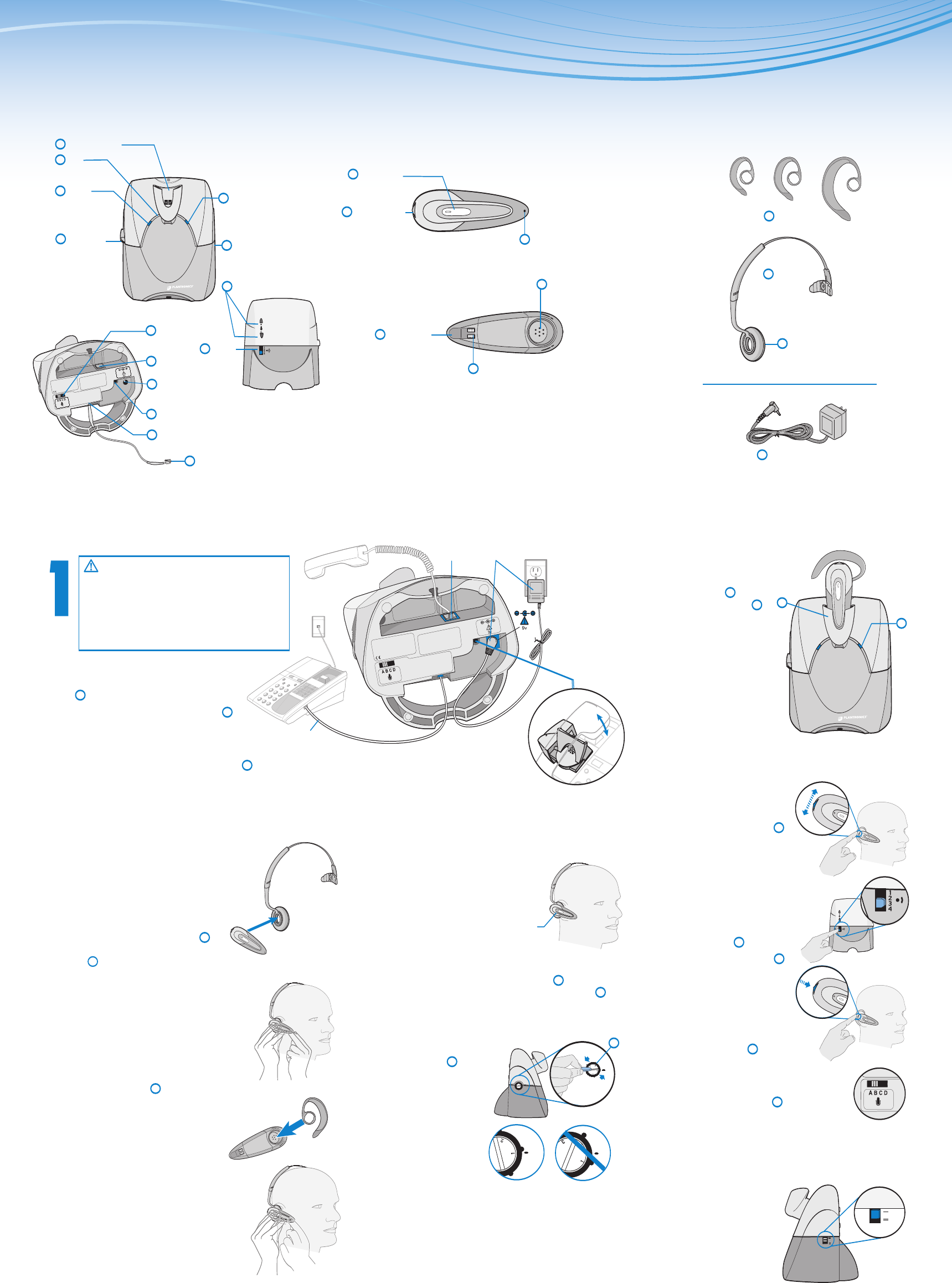
Set Up the Base
1.1 Unplug the curly cord of your handset from
your telephone and insert the handset plug into
the jack on the CS50/55 base with the handset
symbol .
1.2 The CS50/55 base has a short cord
attached. Place the free end of this short
cord into the jack on your telephone where the
handset plug had been connected.
1.3 Connect the supplied AC power adapter to the AC power
adapter jack on the underside of the CS50/55 base and then plug into your power
source. The red power indicator light should go on.
1.4 *Optional: Install the optional handset lifter after you have completed Step 5.
Use the handset lifter instructions to install it. More information on using the
handset lifter with your CS50/55 system is located in the online Product Information
Booklet.
2
CS50/55 WIRELESS OFFICE HEADSET SYSTEM
3
COMPONENTS OF THE CS55™ MICRO SYSTEM
BASE & CHARGING UNITBASE & CHARGING UNIT
Front View
Outside View
Inside View
CORDLESS HEADSETCORDLESS HEADSET WEARING OPTIONSWEARING OPTIONS
Charge the
Headset
2.1 Dock the headset into
the charge cradle . The
amber charge indicator
will flash during charge.
If charge indicator does not
go on, reposition headset
in the cradle.
2.2 The charge indicator
will go steady after headset
is fully charged and ready for
use (approximately 3 hours).
Make Volume and Final
Adjustments
5.1
Adjust your
listening volume
with the listen
volume control
dial located towards the back of
the headset capsule. Rock the
dial up or down for volume
changes.
5.2
For “larger step” adjustments
to your listening volume, change
the position setting on the listen
volume master switch located on
the back of the base .
5.3
Push in the mute control
to activate mute, push in again to
de-activate mute. (You will hear a
slight beep in the speaker when
mute is activated.)
5.4
Adjust your speak volume
(how others hear you) with the
speak volume fine tune buttons
on the back side of the base.
5.5
For “larger step” adjustments to your
speak volume, change the position setting
on the speak volume master switch located
on the bottom of the base.
5.6
You can now activate your IntelliStand feature if you
have installed the optional handset lifter. When enabled,
this feature provides automatic Lifter activation by simply
removing and replacing your
headset in the base unit (no need
to press the talk button on the
headset).
To enable, slide the IntelliStand
switch located on the side
of the base to the on position
(down) or disable by sliding
to the off position (up).
Set Up the
Headset
For over-the-head use
3.1 DDetermine right or left
ear wearing position and
snap the headset speaker capsule
into the headset retainer ring in the
headband .
3.2 While wearing the headset, adjust the
microphone tip toward the corner of your
mouth by rotating the speaker capsule
within the retainer ring.
You may need to hold the headband in
position while doing this, or take off the
headset to adjust it.
OR for over-the-ear use
3.3 Choose the earloop size (small,
medium, or large) that should best fit
your ear. (You may need to experiment
to find the best comfort).
3.4 DDetermine right or left ear wearing
position and snap the headset
speaker capsule into the
earloop ring accordingly.
3.5 While wearing the headset, adjust
the microphone tip toward the corner
of your mouth by rotating the speaker
capsule within the earloop retainer ring.
You may need to hold the earloop in position
while doing this, or take off
the headset to adjust it.
Setup and Test
Your System
4.1
Begin with your
“charged” headset
mounted in the
configuration of your choice.
4.2
Remove the telephone
handset from its base, taking it “off-hook”.
4.3
Press the talk button on the headset.
The talk indicator lights on both the base and
headset should go on, indicating a successful link.
You should now be able to hear a dial tone through
the headset.
4.4
If not, you need to
adjust your telephone
configuration dial on
the base to another one
of its 4 positions until
you hear the tone.
4.5
Continue
configuration setup by
making a test call to a
friend or associate using
the key pad on your
telephone.
4.6
If they cannot hear
you, try changing your telephone configuration
dial on the base to another one of its 4 positions
until you hear them and they hear you. Volume
adjustments can be made separately as
described in the next step.
Listen Volume/
Mute Control
Talk Indicator Light
Talk Button
Small Medium Large
This Quick Start Guide and the Product Information Booklet are located on our website at
www.plantronics.com/documentation/. Choose your language preference and Plantronics model number.
Maintenance and Troubleshooting sections are in the Product Information Booklet at www.plantronics.com/documentation/
3.2
2.1
4.1
5.1
5.3
4.3
3.1
3.3
3.4
3.5
4.4
1.1 1.3
1.4
Back View
Speak Volume
Fine Tune
13
Listen
Volume
Master
11
Power
Indicator
(Red)
Talk
Indicator
(Green)
Charge
Indicator
(Amber)
Charge Cradle
IntelliStand
Switch
10
1
3
2
9
Telephone
Configuration
Dial
4
Underside View
Speak
Volume
Master
Handset
Jack
8
Accessory
Jack
6
AC Power
Adapter
Jack
7
Base Jack
for Telephone
5
12
14
15
Headset
Speaker
Capsule
20
17
Microphone
18
AC Power Adapter
24
Earloops
21
Headband
22
Ear cushion with
replacement foam
cushion cover included
23
19
Underside
of Base
*Optional Telephone
Handset Lifter
1
1
9
9
15
15
11
20
24
21
13
14
2
4
12
Battery Contacts
5.2
5.6
4
5.5
22
8
25
1.2
CAUTION: It is important for correct
and safe operation that the CS50/55 short
cord is installed into the proper jack of your
telephone. Follow these instructions carefully,
especially if your telephone has two jacks
where the handset was attached. Be sure to
note or mark which jack was used for the
handset.
4
5
Short Cord
25