Point Mobile PM260 Handy Terminal User Manual
POINTMOBILE CO., LTD. Handy Terminal Users Manual
UserManual.wiki
>
Point Mobile
>
PM260 User Manual
>
Users Manual
Contents
1.
Users Manual
2.
Users Manaul
Users Manual
Navigation menu
Upload a User Manual
Namespaces
Wiki Guide
HTML
PDF
Info
Views
User Manual
Discussion / Help
Navigation
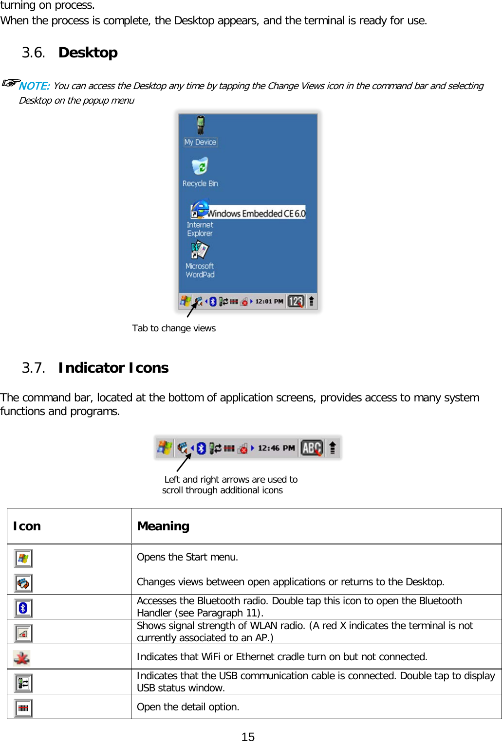
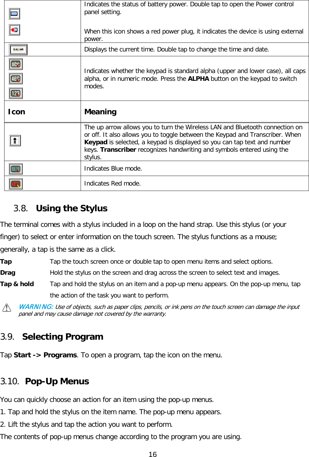
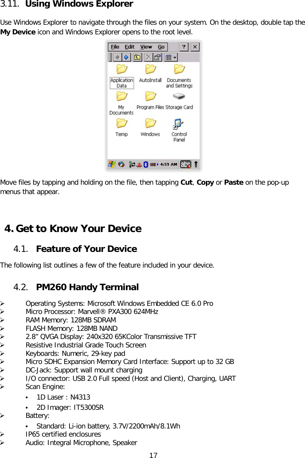
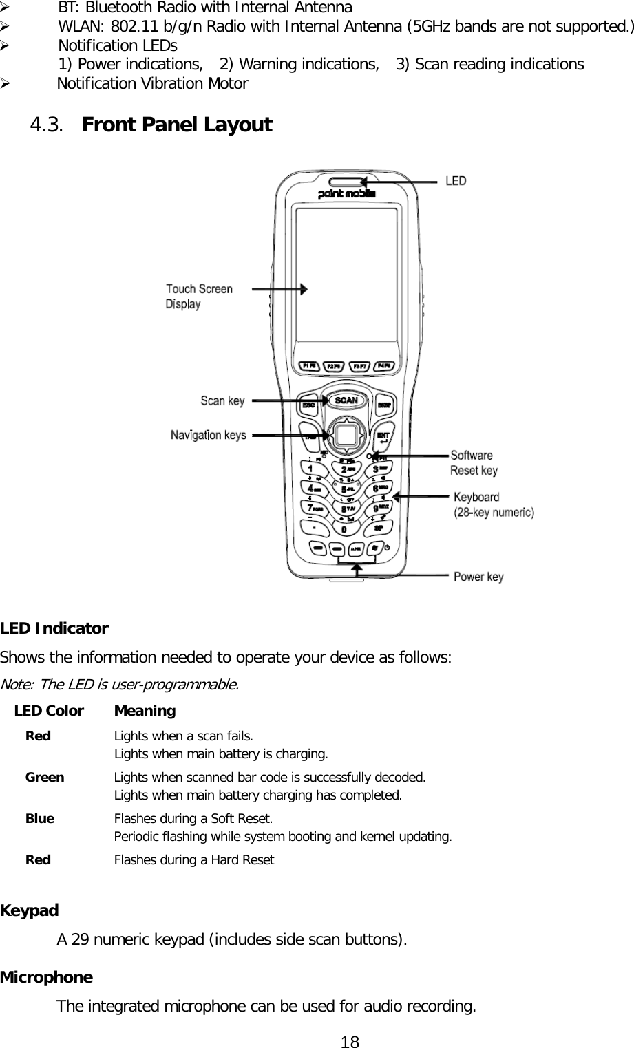
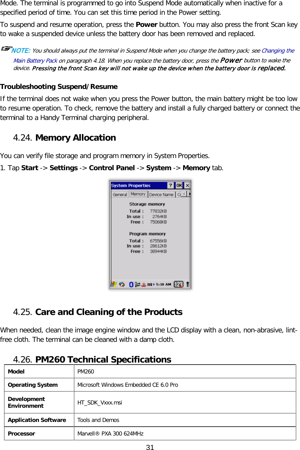
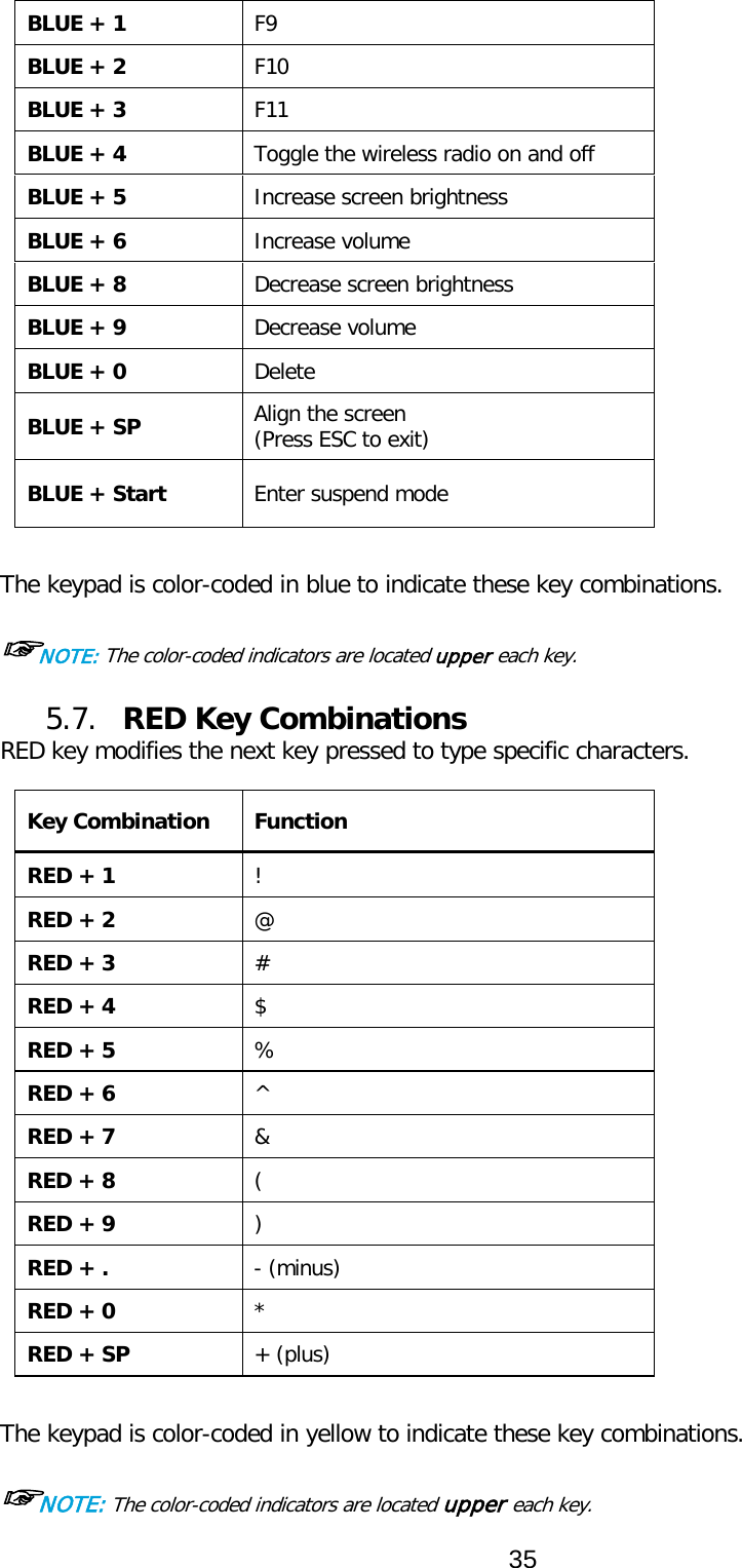
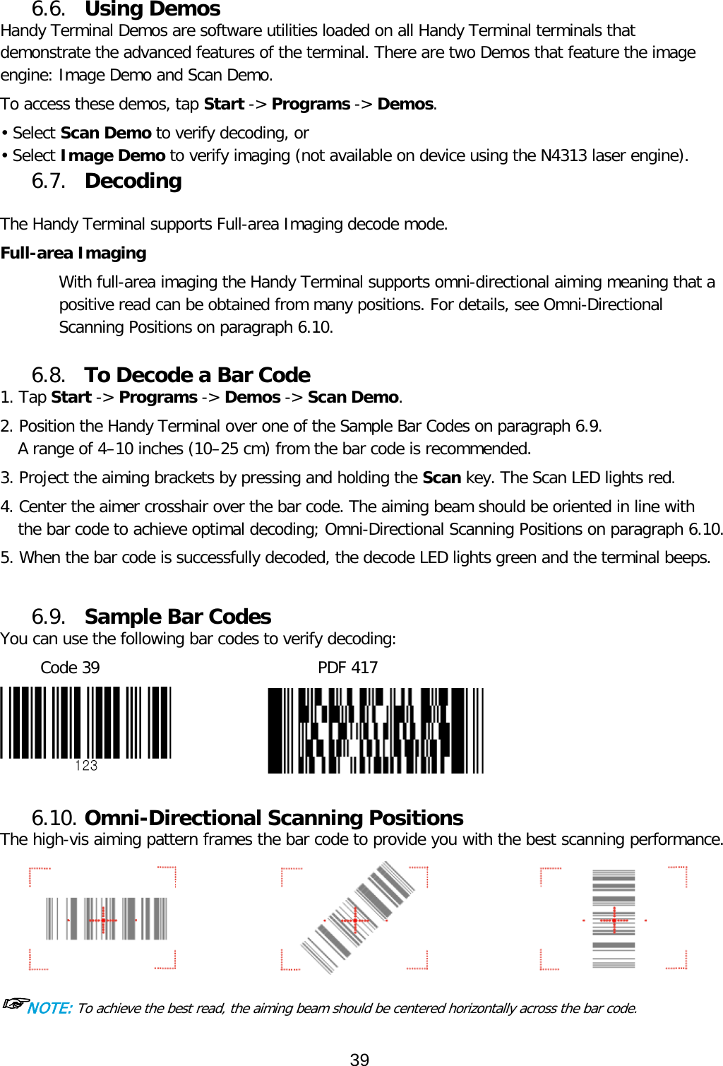
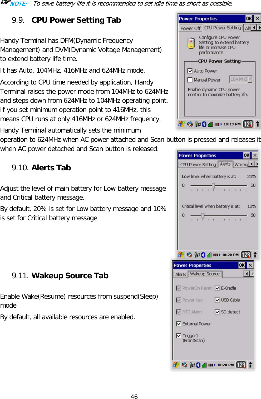
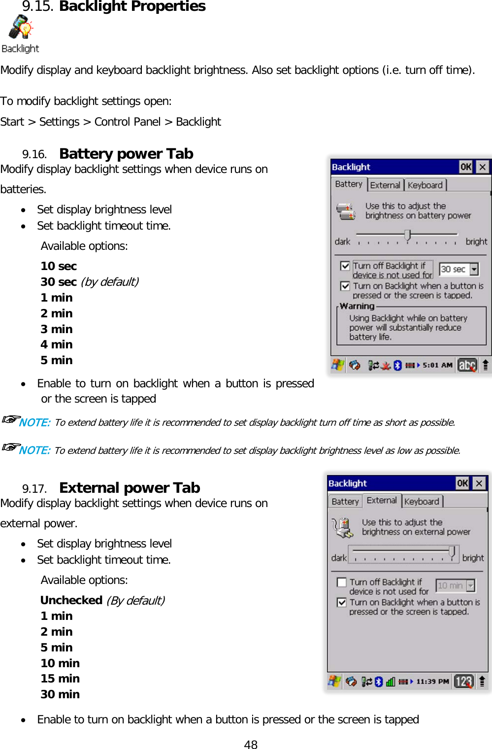
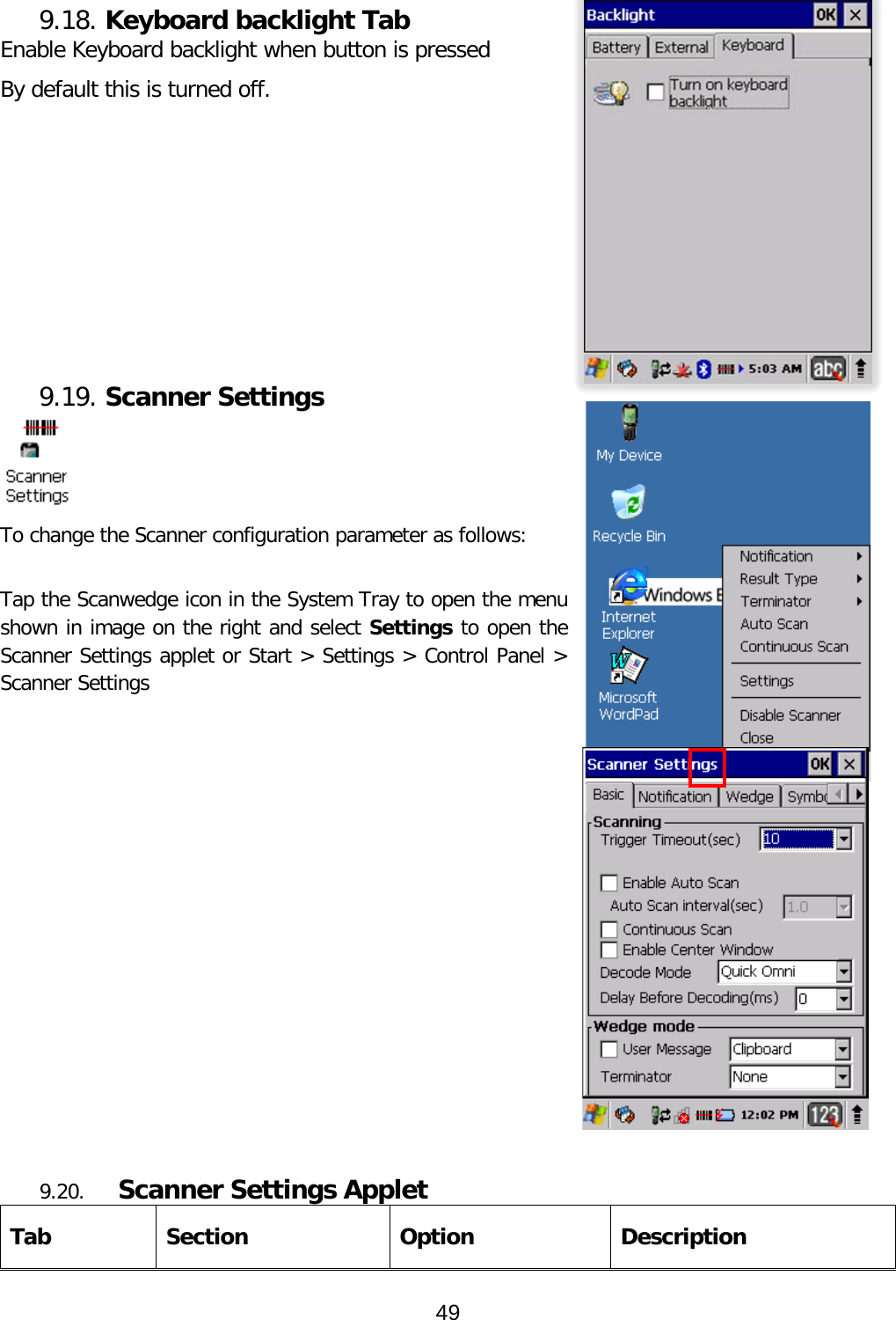
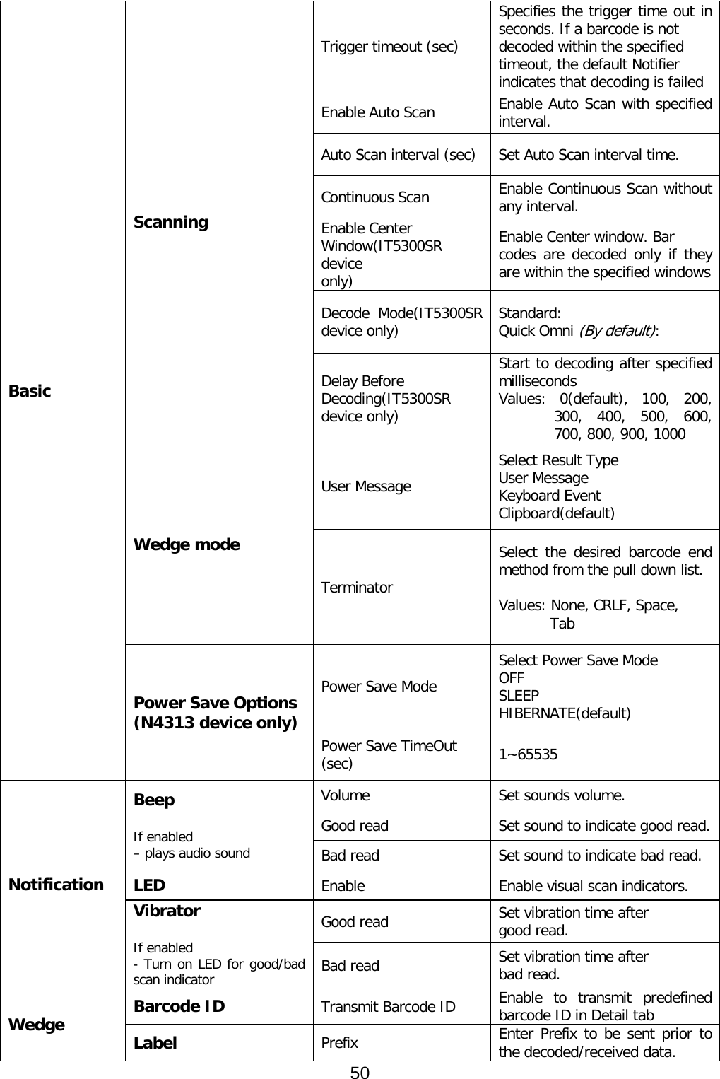
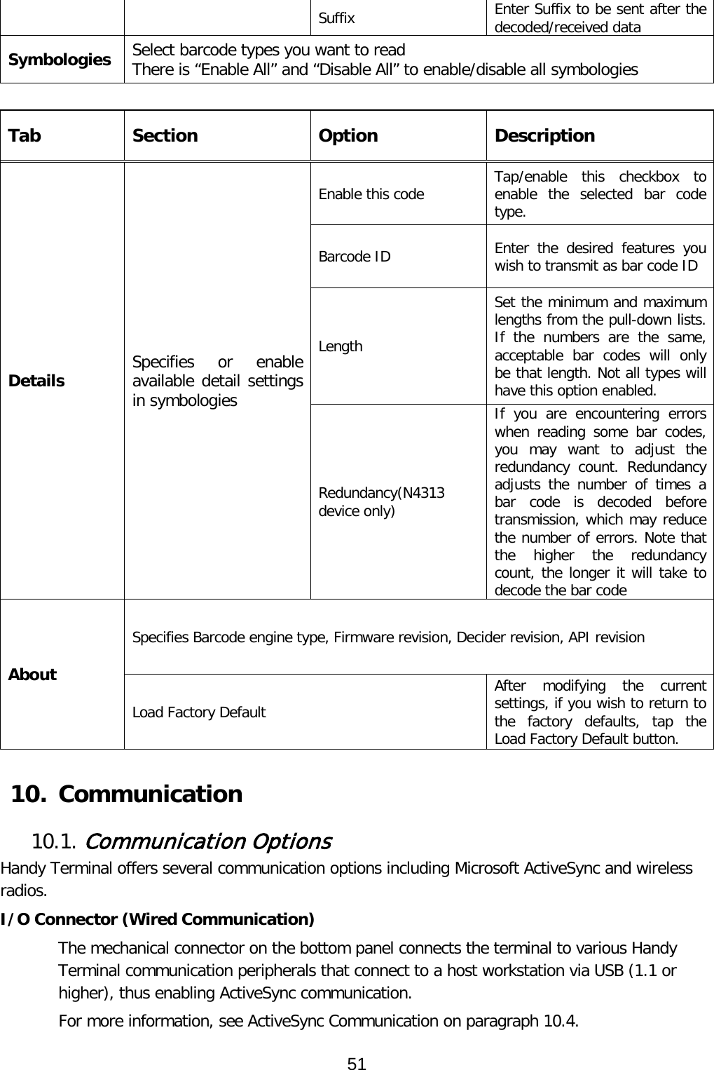
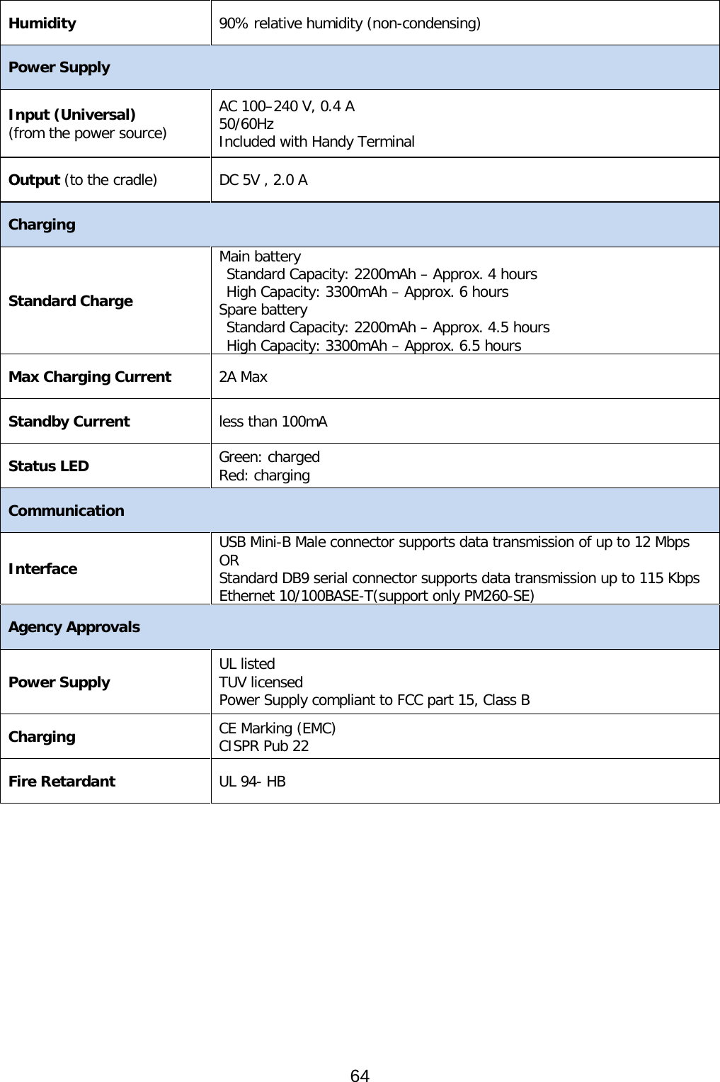
![9.12. Program Button properties 9.13. Program Buttons Tab 1. Select Start > Settings > Control Panel > Program buttons 2. Chose its type: • Default – button will be assigned default function. • No function – button does not have any functions. • Scan key – button is used as Scan key. • Application – click on Open button and select application to bind with this key. 4. To exit, press OK from the command bar, or press the < ENT > key on the keypad 9.14. Key define Tab 1. Select Start > Settings > Control Panel > Program buttons > Key define tab 2. Current key definition file Basic file is set in the windows folder. 3. Chose its type: • Open – button is used to assign new key definition file to [Setting new key define file] edit box. • Apply – button is used to apply [Setting new key define file] to the system. • Default key definition file – button is used to assign basic definition file back. To apply this setting, Click on Apply button. 4. To exit, press OK from the command bar, or press the < ENT > key on the keypad ☞NOTE: It is useful for a customer to want to remap keyboard. 47](https://usermanual.wiki/Point-Mobile/PM260.Users-Manual/User-Guide-1961613-Page-48.png)