Point Mobile PM450G Mobile Computer User Manual
POINTMOBILE CO., LTD. Mobile Computer
UserManual.wiki
>
Point Mobile
>
PM450G User Manual
User Manual
Navigation menu
Upload a User Manual
Namespaces
Wiki Guide
HTML
PDF
Info
Views
User Manual
Discussion / Help
Navigation
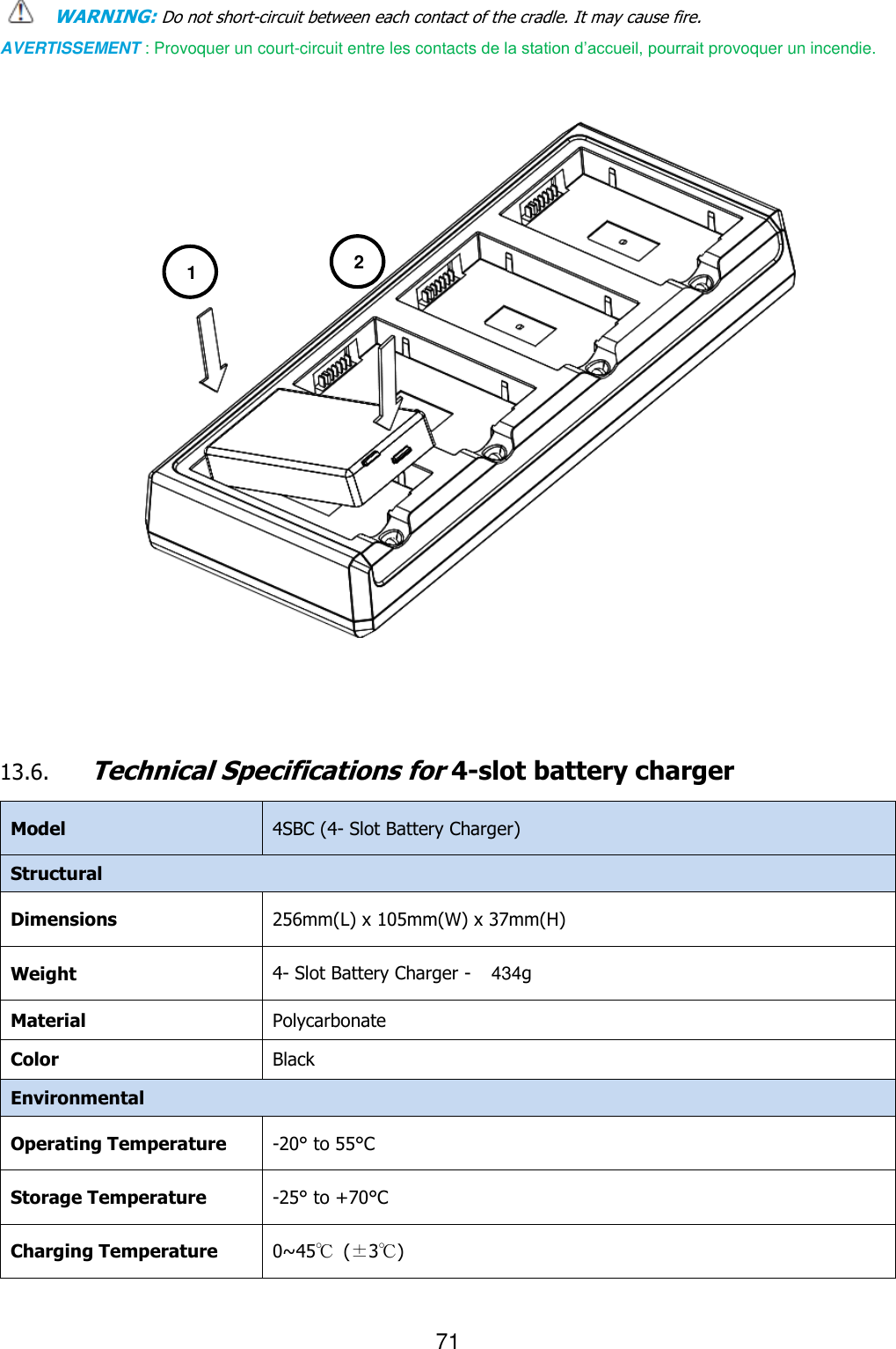
![15 By default, the battery pack is disconnected at the factory to avoid damage due to excessive draining. Annual replacement of rechargeable battery pack avoids possible risks or abnormalities and ensures maximum performance. WARNING: DO NOT attempt to charge damp/wet handy terminals or batteries. All components must be dry before connecting to an external power source. AVERTISSEMENT : NE PAS tenter de recharger les terminaux ou les batteries encore humides lorsqu’ils ont été mouillés. Tous les composants doivent être impérativement séchés avant la connexion à une source d'alimentation externe. WARNING: Never throw a used battery in the trash. It contains heavy metals and should be recycled according to local guidelines. AVERTISSEMENT : Ne jetez pas une batterie usagée à la poubelle. Elle contient des métaux lourds et doit être recyclée conformément aux directives locales. WARNING: Storage of batteries for long time at fully charged status or at fully discharged status should be avoided. Only in case of long storage, in order to avoid deep discharge of the battery, it's recommended to partially recharge the battery every two-three months to keep the charge status at a medium level. AVERTISSEMENT : Le stockage des batteries (à pleine charge ou complètement déchargée) pendant de longues durées doit être évité. Pour éviter une décharge profonde de la batterie en cas de stockage de longue durée ; il est recommandé de recharger partiellement la batterie tous les deux à trois mois pour maintenir l'état de charge à un niveau moyen. WARNING: Installing, charging and/or any other action should be done by authorized personnel and following this manual. The battery pack may get hot, explode, ignite, and/or cause serious injury if exposed to abusive conditions. If the battery pack is replaced with an improper type, there is risk of explosion. Do not place the battery pack in or near a fire or heat; do not place the battery pack in direct sunlight, or use or store the battery pack inside unventilated areas in hot weather; do not place the battery pack in microwave ovens, dryer, high pressure containers, on induction cookware or similar device. Doing so may cause the battery pack to generate heat, explode or ignite. Using the battery pack in this manner may also result in a loss of performance and a shortened life expectancy. Use only a Pointmobile approved power supply. The use of an alternative power supply will void the product warranty, may cause product damage and may cause heat, explode or ignite. The area in which the units are charged should be clear of debris and combustible materials or chemicals. Do not use the battery pack in any other manner outside its intended use in Handy Terminal and peripherals. AVERTISSEMENT : L’installation, la charge et/ou de toute autre action doit être effectuée par du personnel autorisé après lecture de ce manuel. En cas d'utilisation dans des conditions abusives, la batterie peut chauffer, exploser, s'enflammer et/ou causer des blessures graves. L’utilisation d’une batterie inappropriée peut résulter un risque d’explosion N’exposez pas la batterie au feu ou près d’une source de chaleur; ne placez pas la batterie en plein soleil. Par temps chaud, n’utilisez ou ne stockez pas la batterie dans des zones non ventilées. Ne placez pas la batterie dans un four à micro-ondes, un sèche-linge, un conteneur à haute pression, sur une batterie de cuisine à induction ou tout dispositif similaire. La batterie pourrait chauffer, exploser, s'enflammer ou entraîner une perte de performance avec pour conséquence une espérance de vie réduite. N’Utilisez que le bloc alimentation fourni et approuvé par Pointmobile. L'utilisation de tout autre alimentation pourrait engendrer des dommages au produit et provoquer une surchauffe, allant jusqu’à l’explosion ou l'enflammement, et causer la perte de la garantie. Le local dans lequel les terminaux sont rechargés doit être propre et sans aucune présence de matériaux combustibles ou de produits chimiques. Ne pas utiliser la batterie en dehors de l’utilisation prévue pour le terminal portable. [문서에서 멋진 인용문을 가져 오거나 핵심 포인트를 강조하는 공간으로 사용해 보세요. 이 텍스트 상자는 문서 어느 곳에도 끌어다 놓을 수 있습니다.]](https://usermanual.wiki/Point-Mobile/PM450G/User-Guide-2472216-Page-16.png)