Polycom 3725 74600 004 RMX 2000 Administrator’s Guide User Manual To The 72d7abce F41c 4e27 86bb 2c623c8b9f1d
User Manual: Polycom 3725-74600-004 to the manual
Open the PDF directly: View PDF ![]() .
.
Page Count: 624 [warning: Documents this large are best viewed by clicking the View PDF Link!]
- RealPresence Collaboration Server Virtual Edition Overview
- Conference Profiles
- Additional Conferencing Information
- Content Sharing
- H.239 Protocol
- SIP BFCP Content Capabilities
- Defining Content Sharing Parameters for a Conference
- Content Sharing Parameters in Content Highest Common (Content Video Switching) Mode
- Exclusive Content Mode
- Stopping a Content Session
- Content Broadcast Control
- Managing Noisy Content Connections
- Forcing Other Content Capabilities
- Content Sharing via the Polycom CCS Plug-in for Microsoft Lync Clients
- Video Preview (AVC Only Participants)
- Auto Scan and Customized Polling in Video Layout (CP Only)
- Media Encryption
- Packet Loss Compensation (LPR and DBA) AVC CP Conferences
- Lecture Mode (AVC CP Only)
- Audio Algorithm Support
- Permanent Conference
- Content Sharing
- Video Protocols and Resolution Configuration for CP Conferencing
- Cascading Conferences
- Meeting Rooms
- Entry Queues, Ad Hoc Conferences and SIP Factories
- Address Book
- Viewing the Address Book
- Adding Participants from the Address Book to Conferences
- Participant Groups
- Managing the Address Book
- Guidelines
- Adding a Participant to the Address Book
- Adding a New participant to the Address Book Directly
- Adding a Participant from an Ongoing Conference to the Address Book
- Modifying Participants in the Address Book
- Deleting Participants from the Address Book
- Copying or Moving a Participant
- Searching the Address Book
- Filtering the Address Book
- Obtaining the Display Name from the Address Book
- Importing and Exporting Address Books
- Integrating the Global Address Book (GAB) of Polycom RealPresence Resource Manager (XMA) or Polycom CMA™ with the Collaboration Server
- Operator Assistance & Participant Move
- Operator Conferences
- Defining the Components Enabling Operator Assistance
- Defining a Conference IVR Service with Operator Assistance Options
- Defining an Entry Queue IVR Service with Operator Assistance Options
- Defining a Conference Profile for an Operator Conference
- Starting an Ongoing Operator Conference
- Saving an Operator Conference to a Template
- Starting an Operator Conference from a Template
- Monitoring Operator Conferences and Participants Requiring Assistance
- Defining the Components Enabling Operator Assistance
- Audible Alarms
- Moving Participants Between Conferences
- Operator Conferences
- Conference Templates
- Polycom Conferencing for Microsoft Outlook®
- Conference and Participant Monitoring
- Recording Conferences
- Users, Connections, and Notes
- IP Network Services
- IVR Services
- The Call Detail Record (CDR) Utility
- RMX Manager Application
- Accessing the RMX Manager Directly
- Installing the RMX Manager
- Starting the RMX Manager Application
- Adding MCUs to the MCUs List
- Starting a Conference
- Monitoring Conferences
- Modifying the MCU Properties
- Disconnecting an MCU
- Removing an MCU from the MCUs Pane
- Changing the RMX Manager Language
- Import/Export RMX Manager Configuration
- Collaboration Server Administration and Utilities
- System and Participant Alerts
- RMX Time
- Resource Management
- System Information
- SNMP (Simple Network Management Protocol)
- Audible Alarms
- Multilingual Setting
- Banner Display and Customization
- Software Management
- Ping Collaboration Server
- Notification Settings
- Logger Diagnostic Files
- Information Collector
- Auditor
- ActiveX Bypass
- Resetting the Collaboration Server
- Upgrading and Downgrading
- System Configuration Flags
- Disconnection Causes
- Active Alarms
- CDR Fields - Unformatted File
- Ad Hoc Conferencing and External Database Authentication
- Participant Properties Advanced Channel Information
- Secure Communication Mode
- Setting the Collaboration Server for Integration Into Microsoft Environment
- Overview
- Collaboration Server Integration into the Microsoft Lync Server 2010 and Lync Server 2013 Environments
- Configuring the Collaboration Server for Microsoft Integration
- Sharing Content via the Polycom CSS Plug-in for Lync Clients
- Adding Presence to Conferencing Entities in the Buddy List
- Guidelines
- Enabling the Registration of the Conferencing Entities
- Creating an Active Directory Account for the Conferencing Entity
- Enabling the Conferencing Entity User Account for Lync Server
- Defining the Microsoft SIP Server in the IP Network Service
- Enabling Registration in the Conference Profile
- Verifying the Collaboration Server Conferencing Entity Routing Name and Profile
- Monitoring the Registration Status of a Conferencing Entity in the Collaboration Server Web Client or RMX Manager Application
- Connecting a Collaboration Server Meeting Room to a Microsoft AV-MCU Conference
- Active Alarms and Troubleshooting
- SIP RFC Support

[Type the document title]
Polycom Document Title 1
Version 8.2 |October 2013 |3725-74600-004
Polycom® RealPresence® Collaboration Server,
Virtual Edition Administrator’s Guide

© 2013 Polycom®, Inc. All rights reserved.
Polycom®, Inc.
6001 America Center Drive
San Jose CA 95002
USA
No part of this document may be reproduced or transmitted in any form or by any means, electronic or
mechanical, for any purpose, without the express written permission of Polycom®, Inc. Under the law,
reproducing includes translating into another language or format.
As between the parties, Polycom®, Inc., retains title to and ownership of all proprietary rights with respect to
the software contained within its products. The software is protected by United States copyright laws and
international treaty provision. Therefore, you must treat the software like any other copyrighted material (e.g.,
a book or sound recording).
Every effort has been made to ensure that the information in this manual is accurate. Polycom®, Inc., is not
responsible for printing or clerical errors. Information in this document is subject to change without notice.
Trademark Information
POLYCOM® and the names and marks associated with Polycom's products are trademarks and/or service
marks of Polycom, Inc., and are registered and/or common law marks in the United States and various other
countries.
All other trademarks are the property of their respective owners.
Patent Information
The accompanying product may be protected by one or more U.S. and foreign patents and/or pending patent
applications held by Polycom®, Inc.
This document provides the latest information for security-conscious users running Version 8.1 software.
The information in this document is not intended to imply that DoD or DISA certifies Polycom RealPresence
Collaboration Server systems.
End User License Agreement
Use of this software constitutes acceptance of the terms and conditions of the Polycom® RealPresence®
Collaboration Server 800s, Virtual Edition system end-user license agreements (EULA).
The EULA for your version is available on the Polycom Support page for the Polycom® RealPresence®
Collaboration Server 800s, Virtual Edition system.
This software has not achieved UC APL certification.

Table of Contents
Polycom, Inc i
Table of Contents
RealPresence Collaboration Server Virtual Edition Overview . . . . . . . . . . . 1-1
About the RealPresence Collaboration Server Virtual Edition Administrator’s
Guide ........................................................................................................................................ 1-1
Who Should Read This Guide? .................................................................................... 1-2
Prerequisites ............................................................................................................1-2
How This Guide is Organized ...................................................................................... 1-2
About the Polycom® RealPresence Collaboration ServerVirtual Edition System ................. 1-3
IP Networks ............................................................................................................. 1-4
Workstation Requirements ...................................................................................................1-4
Conference Profiles . . . . . . . . . . . . . . . . . . . . . . . . . . . . . . . . . . . . . . . . . . . . . . 2-1
Conferencing Modes .............................................................................................................. 2-1
CP Transcoding - AVC-based Conferencing ...................................................... 2-1
Media Relay - SVC Conferencing .........................................................................2-2
Mixed CP and SVC Conferencing ........................................................................ 2-2
Conferencing Capabilities in the Various Conferencing Modes ............................. 2-2
AVC Conferencing - Video Session Types .........................................................................2-4
Continuous Presence (CP) Conferencing ....................................................................2-4
Video Protocol Support in CP Conferences ........................................................2-5
AVC Conferencing Parameters ....................................................................................2-6
Basic Conferencing Parameters ............................................................................ 2-6
Supplemental Conferencing Features .................................................................2-7
Default Profile Settings in CP Conferencing Mode ................................................... 2-8
SVC-based Conferencing ......................................................................................................2-9
Guidelines ...................................................................................................................... 2-10
MCU Supported Resolutions for SVC Conferencing ......................................2-12
Default Profile Settings in SVC Only Conferencing Mode ..................................... 2-12
Mixed CP and SVC Conferencing ......................................................................................2-13
Default Profile Settings in a Mixed CP and SVC Conferencing Mode ................. 2-14
Resource Capacities for Mixed CP and SVC Conferences ..................................... 2-16
Viewing Profiles ................................................................................................................... 2-18
Profiles Toolbar ............................................................................................................. 2-19
Modifying an Existing Profile ............................................................................................. 2-19
Deleting a Conference Profile ............................................................................................. 2-19
Defining New Profiles .........................................................................................................2-20
Defining AVC CP Conferencing Profiles .................................................................. 2-21
Defining SVC Conferencing Profiles .........................................................................2-45
Defining Mixed CP and SVC Conferencing Profiles ............................................... 2-54
CP Conferencing Additional Information ........................................................................ 2-54
Site Names Definition .................................................................................................. 2-55
Guidelines ..............................................................................................................2-55
Site Names Display Position ............................................................................... 2-56
Message Overlay for Text Messaging ........................................................................ 2-58
Guidelines ..............................................................................................................2-58

Polycom® RealPresence Collaboration Server Virtual Edition Administrator’s Guide
ii Polycom, Inc
Exporting and Importing Conference Profiles .................................................................2-59
Guidelines ......................................................................................................................2-59
Exporting Conference Profiles ....................................................................................2-59
Exporting All Conference Profiles from an MCU ............................................2-59
Exporting Selected Conference Profiles .............................................................2-60
Importing Conference Profiles ....................................................................................2-61
Additional Conferencing Information . . . . . . . . . . . . . . . . . . . . . . . . . . . . . . . .3-1
Content Sharing ......................................................................................................................3-1
H.239 Protocol .................................................................................................................3-1
SIP BFCP Content Capabilities .....................................................................................3-2
Guidelines ................................................................................................................3-2
Defining Content Sharing Parameters for a Conference ...........................................3-3
Content Sharing Parameters in Content Highest Common (Content Video
Switching) Mode .............................................................................................................3-6
Content Settings ......................................................................................................3-7
Content Protocols ....................................................................................................3-8
Selecting a Customized Content Rate in AVC CP Conferences .....................3-13
Exclusive Content Mode ..............................................................................................3-15
Guidelines .............................................................................................................3-15
Stopping a Content Session .........................................................................................3-17
Content Broadcast Control ..........................................................................................3-17
Giving and Cancelling Token Ownership (AVC Participants) ......................3-18
Managing Noisy Content Connections .....................................................................3-19
Content Display Flags ..........................................................................................3-19
Forcing Other Content Capabilities ...........................................................................3-19
Content Sharing via the Polycom CCS Plug-in for Microsoft Lync Clients .........3-20
Video Preview (AVC Only Participants) ...........................................................................3-20
Video Preview Guidelines ...........................................................................................3-20
Workstation Requirements ..........................................................................................3-21
Testing your Workstation ....................................................................................3-21
Previewing the Participant Video ..............................................................................3-22
Auto Scan and Customized Polling in Video Layout (CP Only) ...................................3-23
Guidelines ......................................................................................................................3-23
Enabling Auto Scan and Customized Polling (CP Only) ........................................3-24
Auto Scan ...............................................................................................................3-24
Customized Polling ..............................................................................................3-24
Media Encryption .................................................................................................................3-26
Media Encryption Guidelines .....................................................................................3-26
Mixing Encrypted and Non-encrypted Endpoints in one Conference .........3-27
Direct Connection to the Conference .................................................................3-28
Connection to the Entry Queue ..........................................................................3-29
Moving from the Entry Queue to Conferences or Between Conferences .....3-29
Recording Link Encryption .................................................................................3-30
Encryption Flag Settings ..............................................................................................3-31
Enabling Encryption in the Profile .............................................................................3-32
Enabling Encryption at the Participant Level ...........................................................3-32
Monitoring the Encryption Status ..............................................................................3-33

Table of Contents
Polycom, Inc iii
Packet Loss Compensation (LPR and DBA) AVC CP Conferences .............................. 3-34
Packet Loss ....................................................................................................................3-34
Causes of Packet Loss .......................................................................................... 3-35
Effects of Packet Loss on Conferences ............................................................... 3-35
Lost Packet Recovery ................................................................................................... 3-35
Lost Packet Recovery Guidelines ....................................................................... 3-35
Enabling Lost Packet Recovery .......................................................................... 3-35
Monitoring Lost Packet Recovery .............................................................................. 3-36
Lecture Mode (AVC CP Only) ............................................................................................3-38
Enabling Lecture Mode ...............................................................................................3-38
Selecting the Conference Lecturer ...................................................................... 3-38
Enabling the Automatic Switching .................................................................... 3-40
Lecture Mode Monitoring ........................................................................................... 3-40
Restricting Content Broadcast to Lecturer ................................................................3-42
Muting Participants Except the Lecturer (AVC CP Only) ......................................3-43
Guidelines ..............................................................................................................3-43
Enabling the Mute Participants Except Lecturer Option ................................ 3-44
Audio Algorithm Support ................................................................................................... 3-45
Guidelines ...................................................................................................................... 3-45
SIP Encryption ...................................................................................................... 3-45
Mono .......................................................................................................................3-45
Stereo ......................................................................................................................3-46
Monitoring Participant Audio Properties .................................................................3-47
Permanent Conference ........................................................................................................ 3-49
Guidelines ...................................................................................................................... 3-49
Enabling a Permanent Conference .............................................................................3-49
Video Protocols and Resolution Configuration for CP Conferencing . . . . . 4-1
Video Resolutions in AVC-based CP Conferencing ......................................................... 4-1
Video Display with CIF, SD and HD Video Connections ................................ 4-1
H.264 High Profile Support in CP Conferences ......................................................... 4-2
Guidelines ................................................................................................................4-2
CP Conferencing with H.263 4CIF ............................................................................... 4-2
H.263 4CIF Guidelines ...........................................................................................4-3
The CP Resolution Decision Matrix .....................................................................................4-3
H.264 Base Profile and High Profile Comparison .....................................................4-4
Default Minimum Threshold Line Rates and Resource Usage Summary .............4-6
Resolution Configuration for CP Conferences ................................................................... 4-8
Modifying the Resolution Configuration ...................................................................4-8
Resolution Configuration - Basic .......................................................................... 4-9
Resolution Configuration - Detailed .................................................................. 4-10
Flag Settings ..................................................................................................................4-12
Setting the Maximum CP Resolution for Conferencing ................................ 4-12
Minimum Frame Rate Threshold for SD Resolution ....................................... 4-12
Additional Video Resolutions ............................................................................................ 4-13
Additional Intermediate Video Resolutions ............................................................. 4-13
Microsoft RTV Video Protocol Support in CP Conferences ........................................... 4-13
Guidelines ..............................................................................................................4-13

Polycom® RealPresence Collaboration Server Virtual Edition Administrator’s Guide
iv Polycom, Inc
Participant Settings .......................................................................................................4-15
Monitoring RTV ............................................................................................................4-16
Controlling Resource Allocations for Lync Clients Using RTV Video
Protocol ...........................................................................................................................4-16
Threshold HD Flag Settings using the RTV Video Protocol ..........................4-18
Cascading Conferences . . . . . . . . . . . . . . . . . . . . . . . . . . . . . . . . . . . . . . . . . . .5-1
Video Layout in Cascading conferences (CP and mixed CP and SVC) ..................5-1
Guidelines ................................................................................................................5-2
Flags controlling Cascade Layouts .......................................................................5-2
Basic Cascading .......................................................................................................................5-3
Basic Cascading using IP Cascaded Link ....................................................................5-3
Dialing Directly to a Conference ..........................................................................5-3
Automatic Identification of the Cascading Link ................................................5-4
Meeting Rooms . . . . . . . . . . . . . . . . . . . . . . . . . . . . . . . . . . . . . . . . . . . . . . . . . .6-1
Meeting Rooms List ................................................................................................................6-2
Meeting Room Toolbar & Right-click Menu ...............................................................6-4
Creating a New Meeting Room ............................................................................................6-4
Entry Queues, Ad Hoc Conferences and SIP Factories . . . . . . . . . . . . . . . . .7-1
Entry Queues ...........................................................................................................................7-1
Defining a New Entry Queue ........................................................................................7-3
Listing Entry Queues ......................................................................................................7-6
Modifying the EQ Properties ........................................................................................7-6
Transit Entry Queue .......................................................................................................7-6
Setting a Transit Entry Queue ...............................................................................7-6
SIP Factories .............................................................................................................................7-8
Creating SIP Factories ....................................................................................................7-8
SIP Registration & Presence for Entry Queues and SIP Factories .................................7-10
Guidelines ..............................................................................................................7-10
Monitoring Registration Status ...................................................................................7-10
Ad Hoc Conferencing ...........................................................................................................7-11
Address Book . . . . . . . . . . . . . . . . . . . . . . . . . . . . . . . . . . . . . . . . . . . . . . . . . . .8-1
Viewing the Address Book ....................................................................................................8-2
Displaying and Hiding the Group Members in the Navigation Pane ....................8-3
Participants List Pane Information ...............................................................................8-3
Displaying and Hiding the Address Book ..................................................................8-4
Adding Participants from the Address Book to Conferences ..........................................8-4
Adding Individual Participants from the Address Book to Conferences ..............8-4
Adding a Group from the Address Book to Conferences .........................................8-5
Participant Groups ..................................................................................................................8-6
Managing Groups in the Address Book ......................................................................8-6
Managing the Address Book .................................................................................................8-7
Guidelines ........................................................................................................................8-7
Adding a Participant to the Address Book .................................................................8-7
Adding a New participant to the Address Book Directly ........................................8-8
Substituting E.164 Number in Dial String .........................................................8-13
Adding a Participant from an Ongoing Conference to the Address Book ...........8-14

Table of Contents
Polycom, Inc v
Modifying Participants in the Address Book ........................................................... 8-15
Deleting Participants from the Address Book ..........................................................8-15
Copying or Moving a Participant .............................................................................. 8-16
Searching the Address Book ....................................................................................... 8-17
Filtering the Address Book ......................................................................................... 8-18
Filtering Address Book Data Using a Predefined Pattern .............................. 8-18
Filtering Address Book Data Using a Custom Pattern ................................... 8-19
Clearing the Filter .................................................................................................8-20
Obtaining the Display Name from the Address Book .................................................... 8-21
Guidelines ...................................................................................................................... 8-21
Enabling and Disabling the Obtain Display Name from Address Book
Feature ............................................................................................................................ 8-21
Importing and Exporting Address Books ......................................................................... 8-22
Exporting an Address Book ........................................................................................ 8-22
Importing an Address Book ........................................................................................ 8-22
Integrating the Global Address Book (GAB) of Polycom RealPresence Resource
Manager (XMA) or Polycom CMA™ with the Collaboration Server ........................... 8-23
Operator Assistance & Participant Move . . . . . . . . . . . . . . . . . . . . . . . . . . . . 9-1
Operator Conferences ............................................................................................................ 9-1
Defining the Components Enabling Operator Assistance ....................................... 9-3
Defining a Conference IVR Service with Operator Assistance Options .........9-3
Defining an Entry Queue IVR Service with Operator Assistance Options .... 9-5
Defining a Conference Profile for an Operator Conference ............................. 9-6
Starting an Ongoing Operator Conference .........................................................9-8
Saving an Operator Conference to a Template ................................................ 9-10
Starting an Operator Conference from a Template .........................................9-11
Monitoring Operator Conferences and Participants Requiring Assistance ........9-12
Requesting Help ................................................................................................... 9-12
Participant Alerts List .......................................................................................... 9-13
Audible Alarms .................................................................................................................... 9-13
Using Audible Alarms .........................................................................................9-13
Moving Participants Between Conferences ......................................................................9-14
Moving Participants Options ...................................................................................... 9-15
Conference Templates . . . . . . . . . . . . . . . . . . . . . . . . . . . . . . . . . . . . . . . . . . 10-1
Guidelines ..............................................................................................................10-1
Using Conference Templates ..............................................................................................10-2
Toolbar Buttons .....................................................................................................10-2
Creating a New Conference Template ..............................................................................10-4
Creating a new Conference Template from Scratch ................................................ 10-4
Saving an Ongoing or AVC-based CP Operator Conference as a Template .......10-8
Starting an Ongoing Conference From a Template .........................................................10-9
Starting an Operator Conference from a Template (AVC
Conferencing) ...................................................................................................... 10-10
Deleting a Conference Template ...................................................................................... 10-10
Exporting and Importing Conference Templates ..........................................................10-11
Exporting Conference Templates ............................................................................. 10-11
Exporting All Conference Templates from an MCU ..................................... 10-12

Polycom® RealPresence Collaboration Server Virtual Edition Administrator’s Guide
vi Polycom, Inc
Exporting Selected Conference Templates ......................................................10-13
Importing Conference Templates .............................................................................10-14
Polycom Conferencing for Microsoft Outlook® . . . . . . . . . . . . . . . . . . . . . . .11-1
Setting up the Calendaring Solution ..................................................................................11-2
Calendaring Guidelines ...............................................................................................11-7
Creating and Connecting to a Conference ........................................................................11-9
Creating a Conference ..................................................................................................11-9
Connecting to a Conference ......................................................................................11-10
Collaboration Server Standalone Deployment ...............................................11-10
Collaboration Server and Polycom RealPresence DMA System
Deployment .........................................................................................................11-11
Polycom Solution Support .........................................................................................11-11
Conference and Participant Monitoring . . . . . . . . . . . . . . . . . . . . . . . . . . . . .12-1
General Monitoring ..............................................................................................................12-2
Conference Level Monitoring .............................................................................................12-2
Viewing the Properties of an Ongoing AVC CP and Mixed CP and SVC
Conference .....................................................................................................................12-2
Viewing the Properties of an Ongoing SVC-based Conference ...........................12-11
Monitoring Operator Conferences and Participants Requiring Assistance
(CP and Mixed CP and SVC Conferences) ..............................................................12-16
Requesting Help ..................................................................................................12-16
Request to Speak .................................................................................................12-17
Participant Alerts List .........................................................................................12-18
Participant Level Monitoring ............................................................................................12-19
Displaying Participants Properties ...........................................................................12-19
IP Participant Properties ............................................................................................12-20
Monitoring SIP BFCP Content ..........................................................................12-31
Detecting SIP Endpoint Disconnection ....................................................................12-32
Recording Conferences . . . . . . . . . . . . . . . . . . . . . . . . . . . . . . . . . . . . . . . . . .13-1
Creating Multiple Virtual Recording Rooms on the RSS ................................................13-2
Configuring the Collaboration Server to Enable Recording ..........................................13-2
Defining the Recording Link .......................................................................................13-2
Enabling the Recording Features in a Conference IVR Service .............................13-4
Enabling the Recording in the Conference Profile ...................................................13-5
Recording Link Encryption .........................................................................................13-7
Recording Link Encryption Flag Setting ...........................................................13-7
Recording Link Settings .......................................................................................13-7
Managing the Recording Process .......................................................................................13-8
Recording Link Layout ................................................................................................13-8
Using the Collaboration Server Web Client to Manage the Recording
Process ............................................................................................................................13-9
Using DTMF Codes to Manage the Recording Process ........................................13-11
Users, Connections, and Notes . . . . . . . . . . . . . . . . . . . . . . . . . . . . . . . . . . . .14-1
Users .......................................................................................................................................14-1
User Types .....................................................................................................................14-1
Administrator ........................................................................................................14-1

Table of Contents
Polycom, Inc vii
Administrator Read-only .................................................................................... 14-1
Operator ................................................................................................................. 14-1
Chairperson ...........................................................................................................14-1
Auditor ................................................................................................................... 14-2
Machine Account .................................................................................................. 14-2
Listing Users .................................................................................................................. 14-2
Adding a New User ..................................................................................................... 14-2
Deleting a User .............................................................................................................. 14-3
Changing a User’s Password ......................................................................................14-3
Disabling a User ............................................................................................................ 14-4
Enabling a User ............................................................................................................. 14-5
Renaming a User ..........................................................................................................14-5
Machine Account .......................................................................................................... 14-6
Guidelines ..............................................................................................................14-7
Monitoring ............................................................................................................. 14-7
Active Directory ....................................................................................................14-7
Connections ........................................................................................................................... 14-8
Viewing the Connections List .....................................................................................14-8
Notes ...................................................................................................................................... 14-9
Using Notes ................................................................................................................... 14-9
IP Network Services . . . . . . . . . . . . . . . . . . . . . . . . . . . . . . . . . . . . . . . . . . . . 15-1
IP Network Services ............................................................................................................. 15-1
Management Network (Primary) ............................................................................... 15-2
Default IP Service (Conferencing Service - Media and signaling) ........................ 15-2
Modifying the Management Network ..................................................................... 15-2
Modifying the Default IP Network Service ..............................................................15-7
IP Network Monitoring ..................................................................................................... 15-20
NAT (Network Address Translation) Traversal ............................................................15-25
Deployment Architectures ................................................................................................ 15-25
Remote Connection Using the Internet ................................................................... 15-25
Business to Business Connections ............................................................................15-26
FW (Firewall) NAT Keep Alive ................................................................................15-27
System Configuration in SBC environments .................................................. 15-27
SIP Proxy Failover With Polycom® RealPresence Distributed Media
Application™ (DMA™) 7000 System ..............................................................................15-27
RealPresence Collaboration Server Virtual Edition Network Port Usage ................. 15-28
IVR Services . . . . . . . . . . . . . . . . . . . . . . . . . . . . . . . . . . . . . . . . . . . . . . . . . . . 16-1
IVR Services List ................................................................................................................... 16-1
IVR Services Toolbar .................................................................................................... 16-2
Adding Languages ............................................................................................................... 16-3
Uploading a Message File to the Collaboration Server ........................................... 16-4
Defining a New Conference IVR Service .......................................................................... 16-6
Defining a New Conference IVR Service .................................................................. 16-6
Change to Chairperson ......................................................................................16-18
Entry Queue IVR Service ...................................................................................................16-19
Defining a New Entry Queue IVR Service ..............................................................16-19
Setting a Conference IVR Service or Entry Queue IVR Service as the

Polycom® RealPresence Collaboration Server Virtual Edition Administrator’s Guide
viii Polycom, Inc
Default Service ............................................................................................................16-23
Modifying the Conference or Entry Queue IVR Service Properties ....................16-25
Replacing the Music File ....................................................................................................16-26
Adding a Music File ...........................................................................................16-26
Creating Audio Prompts and Video Slides .....................................................................16-27
Recording an Audio Message ...................................................................................16-27
Creating a Welcome Video Slide ..............................................................................16-30
Default IVR Prompts and Messages ................................................................................16-31
The Call Detail Record (CDR) Utility . . . . . . . . . . . . . . . . . . . . . . . . . . . . . . . .17-1
The CDR File ..........................................................................................................................17-1
CDR File Formats ..........................................................................................................17-1
Multi-Part CDR Files ....................................................................................................17-3
Guidelines ..............................................................................................................17-3
CDR File Contents ........................................................................................................17-3
Viewing, Retrieving and Archiving Conference Information ........................................17-4
Viewing the Conference Records ...............................................................................17-4
Multi-part CDR File display ................................................................................17-5
Refreshing the CDR List ..............................................................................................17-6
Retrieving and Archiving Conference CDR Records ..............................................17-6
RMX Manager Application . . . . . . . . . . . . . . . . . . . . . . . . . . . . . . . . . . . . . . . .18-1
Accessing the RMX Manager Directly ...............................................................................18-1
Installing the RMX Manager ...............................................................................................18-2
Starting the RMX Manager Application ............................................................................18-4
Connecting to the MCU ...............................................................................................18-5
RMX Manager Main Screen .........................................................................................18-7
MCUs Pane ............................................................................................................18-7
Conferences Pane ..................................................................................................18-9
Collaboration Server Management ....................................................................18-9
List Pane ...............................................................................................................18-10
Status Bar ..............................................................................................................18-10
Address Book ......................................................................................................18-11
Conference Templates ........................................................................................18-11
Adding MCUs to the MCUs List ......................................................................................18-11
Starting a Conference .........................................................................................................18-13
Starting a Conference from the Conferences Pane .................................................18-13
Starting an Ongoing Conference From a Template ...............................................18-14
Monitoring Conferences ....................................................................................................18-15
Grouping the Participants by MCU .........................................................................18-16
Start Monitoring/Stop Monitoring ..........................................................................18-17
Modifying the MCU Properties ........................................................................................18-18
Disconnecting an MCU ......................................................................................................18-18
Removing an MCU from the MCUs Pane .......................................................................18-19
Changing the RMX Manager Language ..........................................................................18-19
Import/Export RMX Manager Configuration ................................................................18-20
Collaboration Server Administration and Utilities . . . . . . . . . . . . . . . . . . . . .19-1
System and Participant Alerts .............................................................................................19-1

Table of Contents
Polycom, Inc ix
System Alerts ................................................................................................................19-1
Participant Alerts .......................................................................................................... 19-3
RMX Time .............................................................................................................................. 19-4
Guidelines ..............................................................................................................19-4
Altering the clock ......................................................................................................... 19-4
Resource Management ........................................................................................................ 19-5
Resource Capacity ........................................................................................................ 19-5
Resource Usage .............................................................................................................19-6
SVC Conferencing ................................................................................................ 19-6
AVC Conferencing - Continuous Presence .......................................................19-7
Forcing Video Resource Allocation to CIF Resolution ................................... 19-8
Resource Report ............................................................................................................19-9
Displaying the Resource Report ......................................................................... 19-9
MCU Resource Management by RealPresence Resource Manager (XMA),
Polycom CMA and Polycom RealPresence DMA System ...................................19-11
Guidelines ............................................................................................................19-11
Port Usage Threshold ................................................................................................19-12
Setting the Port Usage Threshold ..................................................................... 19-12
SIP Dial-in Busy Notification ............................................................................ 19-12
Port Usage Gauge .......................................................................................................19-13
System Information ............................................................................................................19-15
SNMP (Simple Network Management Protocol) .......................................................... 19-17
MIBs (Management Information Base) ................................................................... 19-17
Traps ............................................................................................................................. 19-17
Guidelines ............................................................................................................19-17
MIB Files ......................................................................................................................19-17
Private MIBs ........................................................................................................19-17
Support for MIB-II Sections .............................................................................. 19-18
The Alarm-MIB ...................................................................................................19-18
H.341-MIB (H.341 – H.323) ............................................................................... 19-18
Standard MIBs .....................................................................................................19-18
Unified MIB .........................................................................................................19-19
Traps ............................................................................................................................. 19-21
Status Trap ........................................................................................................... 19-22
RMX MIB entities that do not generate traps. ................................................19-22
Defining the SNMP Parameters in the Collaboration Server ...............................19-24
Audible Alarms .................................................................................................................. 19-31
Using Audible Alarms ...............................................................................................19-31
Audible Alarm Permissions ..............................................................................19-32
Stop Repeating Message ....................................................................................19-32
Configuring the Audible Alarms .............................................................................19-32
User Customization ............................................................................................19-32
Replacing the Audible Alarm File .................................................................... 19-33
Multilingual Setting ...........................................................................................................19-35
Customizing the Multilingual Setting ..................................................................... 19-35
Banner Display and Customization ................................................................................. 19-36
Guidelines ............................................................................................................19-36
Non-Modifiable Banner Text .................................................................................... 19-37

Polycom® RealPresence Collaboration Server Virtual Edition Administrator’s Guide
xPolycom, Inc
Sample 1 Banner ..................................................................................................19-37
Sample 2 Banner ..................................................................................................19-37
Sample 3 Banner ..................................................................................................19-37
Sample 4 Banner ..................................................................................................19-37
Customizing Banners .................................................................................................19-38
Banner Display ............................................................................................................19-39
Login Screen Banner ...........................................................................................19-39
Main Screen Banner ............................................................................................19-40
Software Management .......................................................................................................19-40
Backup and Restore Guidelines ................................................................................19-40
Using Software Management ............................................................................19-41
Ping Collaboration Server ..................................................................................................19-42
Guidelines ....................................................................................................................19-42
Using Ping ....................................................................................................................19-42
Notification Settings ...........................................................................................................19-42
Logger Diagnostic Files ......................................................................................................19-44
Information Collector .........................................................................................................19-46
Standard Security Mode ............................................................................................19-46
Using the Information Collector ...............................................................................19-46
Step 1: Creating the Information Collector Compressed File ...............................19-47
Step 2: Saving the Compressed File .........................................................................19-48
Step 3: Viewing the Compressed File ......................................................................19-48
Auditor .................................................................................................................................19-48
Auditor Files ................................................................................................................19-48
Auditor Event History File Storage ..................................................................19-48
Retrieving Auditor Files .....................................................................................19-49
Auditor File Viewer ....................................................................................................19-50
Audit Events ................................................................................................................19-52
Alerts and Faults .................................................................................................19-52
Transactions .........................................................................................................19-54
ActiveX Bypass ....................................................................................................................19-55
Installing ActiveX .......................................................................................................19-55
Resetting the Collaboration Server ...................................................................................19-57
Upgrading and Downgrading ..........................................................................................19-59
System Configuration Flags . . . . . . . . . . . . . . . . . . . . . . . . . . . . . . . . . . . . . .20-1
Modifying System Flags ......................................................................................................20-1
Manually Adding and Deleting System Flags ........................................................20-12
Manually Adding Flags to the CS_MODULE_PARAMETERS Tab ...........20-33
Deleting a Flag .....................................................................................................20-34
Auto Layout Configuration .......................................................................................20-34
Customizing the Default Auto Layout ............................................................20-34
CS_ENABLE_EPC Flag ..............................................................................................20-37
Automatic Password Generation Flags ...................................................................20-37
Guidelines ............................................................................................................20-38
Enabling the Automatic Generation of Passwords ........................................20-38
Appendix A - Disconnection Causes . . . . . . . . . . . . . . . . . . . . . . . . . . . . . . . A-1
IP Disconnection Causes .......................................................................................................A-1

Table of Contents
Polycom, Inc xi
Appendix B - Active Alarms . . . . . . . . . . . . . . . . . . . . . . . . . . . . . . . . . . . . . . . B-1
Appendix C - CDR Fields - Unformatted File . . . . . . . . . . . . . . . . . . . . . . . . . C-1
The Conference Summary Record ...................................................................................... C-2
Event Records ........................................................................................................................ C-3
Standard Event Record Fields ..................................................................................... C-3
Event Types ....................................................................................................................C-4
Event Specific Fields ................................................................................................... C-10
Disconnection Cause Values .............................................................................................. C-33
MGC Manager Events that are not Supported by the Collaboration Server .............. C-36
Appendix D - Ad Hoc Conferencing and External Database
Authentication . . . . . . . . . . . . . . . . . . . . . . . . . . . . . . . . . . . . . . . . . . . . . . . . . . D-1
Ad Hoc Conferencing without Authentication ................................................................D-1
Ad Hoc Conferencing with Authentication ......................................................................D-2
Entry Queue Level - Conference Initiation Validation with an External
Database Application ....................................................................................................D-3
Conference Access with External Database Authentication ...........................................D-4
Conference Access Validation - All Participants (Always) .....................................D-5
Conference Access Validation - Chairperson Only (Upon Request) .....................D-6
System Settings for Ad Hoc Conferencing and External Database Authentication ....D-7
Ad Hoc Settings .............................................................................................................D-7
Authentication Settings ................................................................................................D-8
MCU Configuration to Communicate with an External Database
Application .............................................................................................................D-9
Enabling External Database Validation for Starting New Ongoing
Conferences ..........................................................................................................D-10
Enabling External Database Validation for Conferences Access ..................D-10
Appendix E- Participant Properties Advanced Channel Information . . . . . . E-1
Appendix F- Secure Communication Mode . . . . . . . . . . . . . . . . . . . . . . . . . . F-1
Certificate Configuration and Management ......................................................................F-1
Certificate Template Requirements .............................................................................F-1
Certificate Requirements for Polycom Devices ..........................................................F-2
Configure Certificate Management .............................................................................F-2
Switching to Secure Mode .....................................................................................................F-2
Purchasing a Certificate .................................................................................................F-2
Installing the Certificate ................................................................................................F-4
Creating/Modifying System Flags ..............................................................................F-5
Enabling Secure Communication Mode .....................................................................F-6
Securing an External Database .............................................................................................F-7
MS Active Directory Integration ..........................................................................................F-7
Directory and Database Options ..................................................................................F-7
Standard Security Mode ........................................................................................F-7
Guidelines ........................................................................................................................F-8
Enabling Active Directory Integration ........................................................................F-9
Appendix G - Setting the Collaboration Server for Integration Into Microsoft
Environment . . . . . . . . . . . . . . . . . . . . . . . . . . . . . . . . . . . . . . . . . . . . . . . . . . . . G-1
Overview ................................................................................................................................G-1

Polycom® RealPresence Collaboration Server Virtual Edition Administrator’s Guide
xii Polycom, Inc
Conferencing Entities Presence ....................................................................................G-2
Collaboration Server Integration into the Microsoft Lync Server 2010 and Lync
Server 2013 Environments ....................................................................................................G-3
Configuring the Polycom-Microsoft Solution ...........................................................G-3
Media Over TCP ............................................................................................................G-3
Network Error Recovery ...............................................................................................G-3
SIP Dialog Recovery ......................................................................................................G-3
Content Sharing via Polycom CSS (Content Sharing Suite) Plug-in for Lync
Clients ..............................................................................................................................G-4
Configuring the Collaboration Server for Microsoft Integration ....................................G-4
Modify the Collaboration Server Management Network Service to Include
the DNS Server ...............................................................................................................G-4
Defining a SIP Network Service in the Collaboration Server and Installing
the Security Certificate ..................................................................................................G-6
The Security Certificate .........................................................................................G-6
Configuring the Collaboration Server IP Network Service .............................G-7
Collaboration Server System Flag Configuration ...................................................G-14
Enabling the Microsoft Environment ................................................................G-14
Setting the audio protocol for the Microsoft Client running on a single
core PC ...................................................................................................................G-15
Guidelines .............................................................................................................G-16
Participant Settings ......................................................................................................G-17
Sharing Content via the Polycom CSS Plug-in for Lync Clients ...................................G-18
Guidelines .............................................................................................................G-18
Configuring the MCU for Content Sharing via the Polycom CSS Plug-in ..........G-18
Setting the System Flag .......................................................................................G-19
Conference Profile Settings .................................................................................G-19
Monitoring the Participant connection .............................................................G-20
Adding Presence to Conferencing Entities in the Buddy List .......................................G-22
Guidelines .....................................................................................................................G-22
Enabling the Registration of the Conferencing Entities .........................................G-23
Creating an Active Directory Account for the Conferencing Entity ............G-23
Enabling the Conferencing Entity User Account for Lync Server ................G-25
Defining the Microsoft SIP Server in the IP Network Service .......................G-26
Enabling Registration in the Conference Profile .............................................G-26
Verifying the Collaboration Server Conferencing Entity Routing Name
and Profile .............................................................................................................G-27
Monitoring the Registration Status of a Conferencing Entity in the
Collaboration Server Web Client or RMX Manager Application .........................G-28
Conferencing Entity List .....................................................................................G-28
Conferencing Entity Properties ..........................................................................G-30
Connecting a Collaboration Server Meeting Room to a Microsoft AV-MCU
Conference ............................................................................................................................G-31
Active Alarms and Troubleshooting .................................................................................G-32
Active Alarms ...............................................................................................................G-32
Troubleshooting ...........................................................................................................G-33
Known Issues ................................................................................................................G-34


Polycom® RealPresence Collaboration Server Virtual Edition Administrator’s Guide
xiv Polycom, Inc

Polycom, Inc. 1-1
1
RealPresence Collaboration Server
Virtual Edition Overview
About the RealPresence Collaboration Server Virtual
Edition Administrator’s Guide
The Polycom® RealPresence Collaboration ServerVirtual Edition Administrator’s Guide provides
instructions for configuring, deploying, and administering Polycom Multipoint Control
Units (MCUs) for video conferencing. This guide will help you understand the Polycom
video conferencing components, and provides descriptions of all available conferencing
features. This guide will help you perform the following tasks:
• Optional. Customize the Collaboration Server conferencing entities such as conference
Profiles, IVR Services, Meeting Rooms, Entry Queues, etc., to your organization’s needs.
In the CloudAxis solution environment, these entities should be defined in the Polycom
RealPresence Distributed Media Application (DMA) system.
• Define Collaboration Server Users.
• Advanced conference Management
• Define Video Protocols and Resolution Configuration for CP Conferencing
• Optional. Configure Templates and the Address Book. In the CloudAxis solution
environment, these entities should be defined in the RealPresence DMA system.
• Record Conferences
• Configure the Collaboration Server to support special call flows and conferencing
requirements, such as Cascading Conferences.
• Configure the Collaboration Server for special applications and needs by setting
various system flags.
• Manage and troubleshoot the Collaboration Server’s performance.
The Polycom® RealPresence Collaboration Server Virtual Edition Getting Started Guide provides
description of basic conferencing operations. It will help you perform the following tasks:
• Perform basic configuration procedures.
• Start a new conference and connect participants/endpoints to it.
• Monitor ongoing conferences
• Perform basic operations and monitoring tasks

Polycom® RealPresence Collaboration ServerVirtual Edition Administrator’s Guide
1-2 Polycom, Inc.
Who Should Read This Guide?
System administrators and network engineers should read this guide to learn how to
properly set up Polycom Collaboration Server systems. This guide describes administration-
level tasks.
For detailed description of first time installation and configuration, description of the
Collaboration Server Web Client, and basic operation of your Collaboration Server system, see
the Polycom® RealPresence Collaboration Server Virtual Edition Getting Started Guide.
Prerequisites
This guide assumes the user has the following knowledge:
• Familiarity with Windows® XP or Windows 7 operating systems and interface.
• Familiarity with Microsoft® Internet Explorer® Version 7, 8 or 9.
• Basic knowledge of video conferencing concepts and terminology.
How This Guide is Organized
The following typographic conventions are used in this guide to distinguish types of in-text
information.
Table 1-1 Typographic Conventions
Convention Description
Bold Highlights interface items such as menus, soft keys, flag names, and
directories. Also used to represent menu selections and text entry to the
phone.
Italics Used to emphasize text, to show example values or inputs, file names and to
show titles of reference documents available from the Polycom Support Web
site and other reference sites.
Underlined Blue Used for URL links to external Web pages or documents. If you click on text in
this style, you will be linked to an external document or Web page.
Blue Text Used for cross referenced page numbers in the same or other chapters or
documents. If you click on blue text, you will be taken to the referenced
section.
Also used for cross references. If you click the italic cross reference text, you
will be taken to the referenced section.
<variable name> Indicates a variable for which you must enter information specific to your
installation, endpoint, or network. For example, when you see <IP address>,
enter the IP address of the described device.
>Indicates that you need to select an item from a menu. For example,
Administration > System Information indicates that you need to select
System Information from the Administration menu.
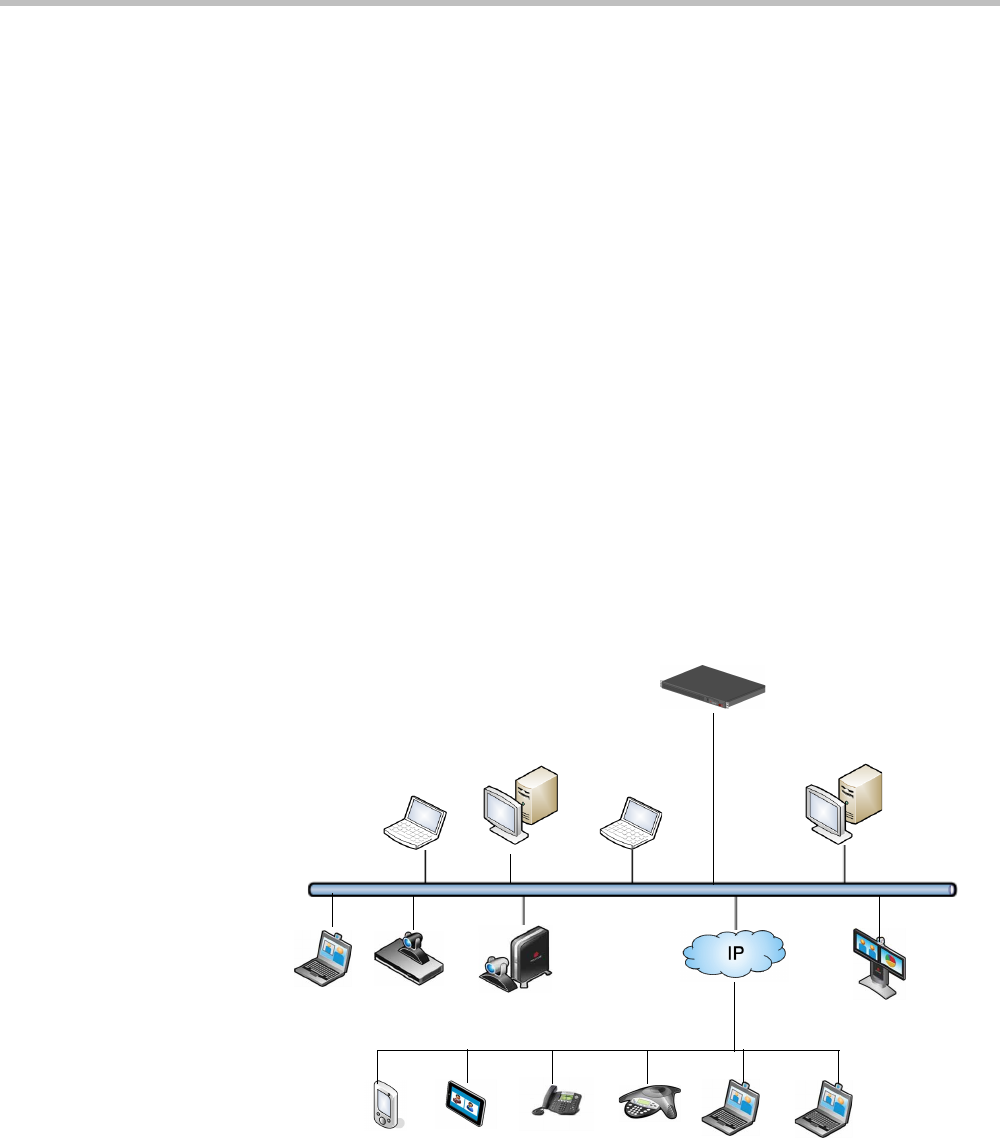
Chapter 1-RealPresence Collaboration Server Virtual Edition Overview
Polycom, Inc. 1-3
About the Polycom® RealPresence Collaboration
ServerVirtual Edition System
The RealPresence Collaboration Server Virtual Edition system is a high performance, scalable,
IP-network (H.323 and SIP) MCU that provides feature-rich and easy-to-use multipoint
voice and video conferencing.
The MCU can be used as a standalone device to run voice and video conferences or it can be
used as part of a solution provided by Polycom. This solution may include the following
components:
•Polycom® RSS™ 4000 - provides one-touch recording and secure playback on video
conferencing systems, tablets and smartphones, or from your Web browser.
•Polycom® Distributed Media Application™ (DMA™) system - provides call control and
MCU virtualization with carrier-grade redundancy, resiliency and scalability.
•Polycom Real Presence Resource Manager - centrally manages, monitors and delivers
Cloud based Video as a Service (VaaS) and enterprise video collaboration.
•Polycom® RealPresence® Access Director™ (RPAD) - removes communication barriers
and enables internal and external teams to collaborate more easily and effectively over
video.
The following diagram describes the multipoint video conferencing configuration with the
Collaboration Server as a standalone system.
Figure 1-1 Multipoint Video Conferencing using a Polycom Collaboration Server
Collaboration Server
Web Client
Desktop
IP Phone
Endpoints
Polycom® RealPresence
Collaboration ServerVirtual
Edition
LAN
Mobile

Polycom® RealPresence Collaboration ServerVirtual Edition Administrator’s Guide
1-4 Polycom, Inc.
The RealPresence Collaboration Server Virtual Edition unit can be controlled via the LAN
by the Collaboration Server Web Client application using Internet Explorer installed on the
user’s workstation, or the RMX Manager application. The RMX Manager can control several
Collaboration Server units. For more information about the RMX Manager see "RMX
Manager Application” on page 18-1.
IP Networks
In the Polycom® RealPresence Collaboration ServerVirtual Edition, system management
and IP conferencing are performed via a single LAN port.
Workstation Requirements
The Collaboration Server Web Client and RMX Manager applications can be installed in an
environment that meets the following requirements:
•Minimum Hardware – Intel® Pentium® III, 1 GHz or higher, 1024 MB RAM,
500 MB free disk space.
•Workstation Operating System – Microsoft® Windows® XP, Windows® 7, and
Windows® 8.
•Network Card – 10/100/1000 Mbps.
•Web Browser - Microsoft® Internet Explorer® Version 7, 8, 9, and 10.
• Collaboration Server Web client and RMX Manager are optimized for display at a
resolution of 1280 x 800 pixels and a magnification of 100%.
R
Internet Explorer must be enabled to allow running Signed ActiveX.
If ActiveX installation is blocked please see "ActiveX Bypass” on page 19-55.
Collaboration Server Web Client does not support larger Windows text or font sizes. It is
recommended to set the text size to 100% (default) or Normal in the Display settings in Windows
Control Panel on all workstations. Otherwise, some dialog boxes might not appear properly aligned.
To change the text size, select Control Panel>Display. For Windows XP, click the Appearance tab,
select Normal for the Font size and click OK. For Windows 7, click the Smaller - 100% option and
click OK.
When installing the Collaboration Server Web Client, Windows Explorer >Internet Options>
Security Settings must be set to Medium or less.
It is not recommended to run Collaboration Server Web Client and Polycom CMAD applications
simultaneously on the same workstation.
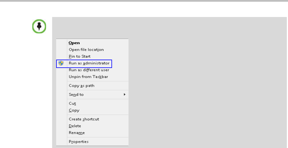
Chapter 1-RealPresence Collaboration Server Virtual Edition Overview
Polycom, Inc. 1-5
For Windows 7™ Security Settings, see the Polycom® RealPresence Collaboration Server Virtual
Edition Getting Started Guide, "Microsoft Windows 7™ Security Settings” on page 1-12.
For Internet Explorer 8 configuration, see the Polycom® RealPresence Collaboration Server
Virtual Edition Getting Started Guide, "Microsoft Windows 7™ Security Settings” on page 1-12.
If you have problems getting the Collaboration Server Web Client to work with Windows 8, it is
recommended to run Internet Explorer as an administrator by holding the shift key and right-clicking
on the IE icon, and then select Run as Administrator.

Polycom® RealPresence Collaboration ServerVirtual Edition Administrator’s Guide
1-6 Polycom, Inc.

Polycom, Inc. 2-1
2
Conference Profiles
Profiles stored on the Collaboration Server enable you to define all types of conferences.
Profiles include conference parameters such as Conferencing Mode, Conference Session
Type, Conference Line Rate, video and Video Layout, Encryption, Lost Packet Recovery
(LPR), etc.
The maximum number of Conference Profiles that can be defined is 80.
Conference Profiles are assigned to Conferences, Meeting Rooms, and Entry Queues. The
same Profile can be assigned to different conferencing entities. When modifying the Profile
parameters, the changes will be applied to all the conferencing entities to which the profile is
assigned.
Conference Profile options differ according to the selected Conferencing Mode and Conference
Type. Profiles can be defined for AVC (Advanced Video Codec) CP conferencing Mode or
SVC (Scalable Video Codec) conferencing Mode. AVC Conferencing Mode, offers two Video
Session types: Continuous Presence (CP) conferences and Video Switching (VSW)
conferences, and a special functional conference - Operator Conferences.
Conference Profiles can be saved to Conference Templates along with all participant parameters,
including their Personal Layout and Video Forcing settings. It enables administrators and
operators to create, save, schedule and activate identical conferences quickly and easily. For
more information see Chapter 10, “Using Conference Templates” .
Conferencing Modes
The MCU system offers the following Conferencing Modes:
• Transcoding - AVC Conferencing
• Media Relay - SVC Conferencing
• Mixed Mode - Mixed AVC (CP) and SVC Conferencing
CP Transcoding - AVC-based Conferencing
A transcoded CP (Continuous Presence) conference is also described as an AVC (Advanced
Video Coding) conference. It supports the standard video protocols. In this mode, video is
received from all the endpoints using different line rates, different protocols (SIP, H.323)
and video parameters:
• Video protocols: H.263, H.264 Base and High profile and RTV
• Video Resolutions: from QCIF, CIF and up to 720p
• Frame rates up to 30 fps
In the RealPresence CloudAxis Solution, the Conference Profiles are defined in the RealPresence
DMA system component and should not be defined directly in the RealPresence Collaboration
Server Virtual Edition component.

Polycom® RealPresence Collaboration ServerVirtual Edition Administrator’s Guide
2-2 Polycom, Inc.
All endpoints that do not support the H.264 SVC protocol such as H.263, H.264, or RTV, are
considered AVC endpoints.
The MCU processes the received video, transcodes it and sends the resulting video streams
to the endpoints. The video processing that is required differs according to the video session
set for the conference, with all the processing performed by the MCU. For more details, see
"AVC Conferencing - Video Session Types” on page 2-4.
Media Relay - SVC Conferencing
Media Relay SVC Conferencing is based on the SVC (Scalable Video Codec) video protocol
and SAC audio protocol. It offers high resolution video conferencing with low end-to-end
latency, improved Error Resiliency and higher system capacities.
The Polycom multipoint media server, serves as an integrated media relay engine that
provides media streams for displaying conferences at low latency video experience in video
conferences. For more details see, "SVC-based Conferencing” on page 2-9.
Mixed CP and SVC Conferencing
This type of conference enables participants with SVC-enabled endpoints and AVC
endpoints to participate in the same conference.
Each endpoint connects according to its capabilities. The MCU processes the AVC video
streams and converts them into SVC video Streams and relays them to the SVC participants
that constructs the video layout on the endpoint.
In the same way, the MCU processes the video streams received from the SVC participants,
converts them into AVC video and then transcodes all the video streams to compose the
video layout that is sent to the AVC endpoints.
Conferencing Capabilities in the Various Conferencing Modes
The following table summarizes the conferencing capabilities and options available in the
different Conferencing Modes.
Table 2-1 Conferencing Capabilities in the Different Conferencing Modes
Feature CP Only Mixed CP & SVC SVC Only
Operator
Conferences
Entry Queues ***
Permanent
Conference
Cascading ** **
IVR
Reduced IVR set for
SVC endpoints
Dial Out

Chapter 2-Conference Profiles
Polycom, Inc. 2-3
* Entry Queue & Destination Conference must have the same profile (i.e. SVC only to SVC only, Mixed
CP and SVC to Mixed CP and SVC)
** Only Basic Cascading is available
*** For AVC, the LPR error resiliency is used, however for SVC endpoints, new error resiliency
methods are used.
Auto Redial
LPR *** ***
Content
All Content Settings,
All Content Protocols
Graphics Only,
H.264 Cascade &
SVC Optimized
Graphics Only, H.264
Cascade & SVC
Optimized
Presentation Mode
Lecture Mode
Same Layout
Layout Selection
AVC endpoints only
Layout set to Auto
Layout and defined on
the endpoint
Skins
AVC endpoints only
Encryption
Recording
AVC recording only
Site Names
AVC endpoints only
Managed by the
endpoint (not via MCU)
Table 2-1 Conferencing Capabilities in the Different Conferencing Modes (Continued)
Feature CP Only Mixed CP & SVC SVC Only

Polycom® RealPresence Collaboration ServerVirtual Edition Administrator’s Guide
2-4 Polycom, Inc.
AVC Conferencing - Video Session Types
All endpoints have AVC capabilities and can connect to AVC conferences running on the
MCU. AVC-based Endpoints can connect using different signaling protocols and different
video protocols.
Continuous Presence (CP) Conferencing
The dynamic Continuous Presence (CP) capability of the Collaboration Server system
enables viewing flexibility by offering multiple viewing options and window layouts for
video conferencing.
Endpoints can connect to the conference using any signaling protocol (H.323, SIP and RTV),
line rate (up to a maximum line rate defined for the conference), Video Protocol (H.261,
H.263, H.264 Base and High Profile) and at any resolution and frame rate (provided they
meet the minimum requirements set for the conference).
In Continuous Presence conferences, the MCU receives the video stream from each
endpoint at the video rate, video resolution and frame rate that it is capable of sending, and
it superimposes all the received streams into one video stream that includes the input from
the other endpoints arranges in the selected video layout.
Participants do not see themselves in the video layout. By Default, the speaker is shown in
the top left layout cell in symmetric layouts, in the larger cell in asymmetric layouts, or in
full screen. The speaker sees the previous speakers (their number depends on the number of
cells on the speaker’s layout.
The Continuous Presence video session offers layouts to accommodate different numbers of
participants and conference settings including support of the VUI annex to the H.264
protocol for endpoints that transmit wide video instead of 4CIF resolution. Each participant
can select his/her layout for viewing during the conference, as can be seen in Figure 2-1.
For conferences with more participants than display squares, the Collaboration Server
dynamic video mix capability allows the viewed sites to be modified throughout the
conference. The displayed layout can be changed during an ongoing conference, allowing a
participant to view different screen layouts of the other conference participants. These
layout options allow conferences to have greater flexibility when displaying a large number
of participants and maximizes the screen’s effectiveness.
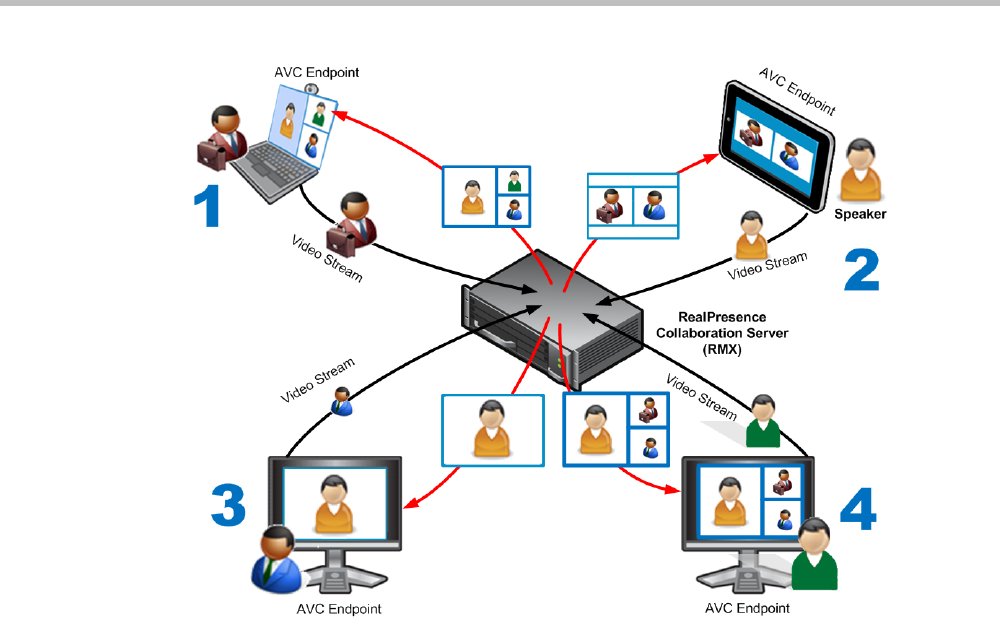
Chapter 2-Conference Profiles
Polycom, Inc. 2-5
Figure 2-1 AVC Continuous Presence (CP) video streams and built layouts
Video quality in Continuous Presence conferences is affected by the conference line rate
(that determines the maximum line rate to be used by the connecting endpoints), and the
video capabilities of the endpoints such as the video protocol, video resolution and frame
rate. Content sharing is available in all CP conferences.
This requires extensive processing of the video sent to each participant in the conference.
The higher the video rate and resolution, the more processing power is required.
By default every conference, Entry Queue and Meeting Room has the ability to declare the
maximum CP resolution as defined for the system. This includes conferences launched by
the Collaboration Server Web Client and conferences started via the API.
CP conferencing is defined in the Conference profile by setting the following main features:
• Setting the Conferencing Mode to AVC only
• Conference Line Rate
•Video Layout
Video Protocol Support in CP Conferences
The video protocol selected by the system determines the video compression standard used
by the endpoints. In Continuous Presence conferences, the system selects the best video
protocol for each of the endpoint according to he endpoint’s capabilities.
The following Video protocols are supported in CP conferences:
•H.261 - the legacy video compression algorithm mandatory to all endpoints. It is used
by endpoints that do not support other protocols.
•H.263 - a video compression algorithm that provides a better video quality than H.261.
This standard is not supported by all endpoints.

Polycom® RealPresence Collaboration ServerVirtual Edition Administrator’s Guide
2-6 Polycom, Inc.
•H.264 Base Profile - a video compression standard that offers improved video quality,
especially at line rates lower than 384 Kbps.
H.264 High Profile allows higher quality video to be transmitted at lower line rates.
•RTV - a video protocol that provides high quality video conferencing capability to
Microsoft OCS (Office Communicator Server) endpoints at resolutions up to HD720p30.
(SIP only).
AVC Conferencing Parameters
When defining a new video Profile, you select the parameters that determine the video
display on the participant’s endpoint and the quality of the video. When defining a new
conference Profile, the system uses default values for Continuous Presence (CP) standard
conferencing. Continuous Presence conferencing enables several participants to be viewed
simultaneously and each connected endpoint uses its highest video, audio and data
capabilities up to the maximum line rate set for the conference.
Basic Conferencing Parameters
The main parameters that define the quality of a video conference are:
•Line (Bit) Rate - The transfer rate of video and audio streams. The higher the line (bit)
rate, the better the video quality.
•Audio Algorithm - The audio compression algorithm determines the quality of the
conference audio.
•Video protocol, video format, frame rate, annexes, and interlaced video mode - These
parameters define the quality of the video images. The Collaboration Server will send
video at the best possible resolution supported by endpoints regardless of the
resolution received from the endpoints.
—When Sharpness is selected as the Video Quality setting in the Conference Profile, the
Collaboration Server will send 4CIF (H.263) at 15fps instead of CIF (H.264) at 30fps.
—H.264 High Profile protocol provides better compression of video images in line
rates lower than 384 Kbps and it will be automatically selected for the endpoint if it
supports H.264 High Profile. If the endpoint does not support H.264 High Profile,
the Collaboration Server will try H.264 Base Profile which provides good
compression of video images in line rates lower than 384 Kbps (better than H.263
and not as good as H.264 High Profile).
—When working with Collaboration Servers at low bit rates (128, 256, or 384Kbps),
HDX endpoints will transmit SD15 resolution instead of 2CIF resolution.
When using a full screen (1x1) conference layout, the Collaboration Server transmits the
same resolution it receives from the endpoint.
• Supported resolutions:
—H.261 CIF/QCIF – Is supported in Continuous Presence (CP) conferences at
resolutions of 288 x 352 pixels (CIF) and 144 x 176 pixels (QCIF). Both resolutions
are supported at frame rates of up to 30 frames per second.
—H.263 4CIF - A high video resolution available to H.263 endpoints that do not
support H.264. It is only supported for conferences in which the video quality is set
to sharpness and for lines rates of 384kbps to 1920kbps.
—Standard Definition (SD) - A high quality video protocol which uses the H.264
and H.264 High Profile video algorithms. It enables compliant endpoints to
connect to Continuous Presence conferences at resolutions of 720 x 576 pixels for

Chapter 2-Conference Profiles
Polycom, Inc. 2-7
PAL systems and 720 x 480 pixels for NTSC systems. For more information, see
"Video Resolutions in AVC-based CP Conferencing” on page 4-1.
—High Definition (HD) – HD is an ultra-high quality video resolution that uses the
H.264 and H.264 High Profile video algorithms. Depending on the Collaboration
Server’s Card Configuration mode compliant endpoints are able to connect to
conferences at the following resolutions:
•720p (1280 x 720 pixels)
"Video Resolutions in AVC-based CP Conferencing” on page 4-1.
•Lost Packet Recovery (LPR) - LPR creates additional packets that contain recovery
information used to reconstruct packets that are lost during transmission.
Supplemental Conferencing Features
In addition to basic parameters that determine the quality of the video, additional features can
be enabled, adding capabilities to the conference, or enabling special conferencing modes:
•Content Sharing (H.239) – Allows compliant endpoints to transmit and receive two
simultaneous streams of conference data to enable Content sharing. H.239 is also
supported in cascading conferences. Both H.263 and H.264 Content sharing protocols
are supported. If all endpoints connected to the conference have H.264 capability,
Content is shared using H.264, otherwise Content is shared using H.263.
For more information, see "Content Sharing” on page 3-1.
•Encryption – Used to enhance media security at conference and participant levels. For
more information, see "Media Encryption” on page 3-26.
•Conference Recording - The Collaboration Server enables audio and video recording of
conferences using Polycom RSS recording system.
•Lecture Mode – The lecturer is seen by all participants in full screen while the lecturer
views all conference participants in the selected video layout.
For more information, see "Lecture Mode (AVC CP Only)” on page 3-38.
•Presentation Mode (CP Conferences only) – When the current speaker’s speech
exceeds a predefined time (30 seconds), the conference layout automatically changes to
full screen, displaying the current speaker as the conference lecturer on all the
participants’ endpoints. During this time the speaker’s endpoint displays the previous
conference layout. When another participant starts talking, the Presentation Mode is
cancelled and the conference returns to its predefined video layout. Presentation mode
is available with Auto Layout and Same Layout.
—If the speaker in a video conference is an Audio Only participant, the Presentation
Mode is disabled for that participant.
—Video forcing works in the same way as in Lecture Mode when Presentation Mode
is activated, that is, forcing is only enabled at the conference level, and it only
applies to the video layout viewed by the lecturer.

Polycom® RealPresence Collaboration ServerVirtual Edition Administrator’s Guide
2-8 Polycom, Inc.
Default Profile Settings in CP Conferencing Mode
The Collaboration Server is shipped with a default Conference Profile for CP conferences
which allows users to immediately start standard ongoing CP conferences. These are also
the default settings when creating a new Profile.
The default settings are as follows
:
Table 2-2 Default CP Only Conference Profile Settings
Setting Value
Profile Name Factory_Video_Profile
Line Rate 384Kbps
Operator Conference Disabled
Encryption Disabled
Packet Loss Compensation (LPR
and DBA)
Enabled
Auto Terminate •After last participant quits - Enabled
•When last participant remains - Disabled
Auto Redialing Disabled
Exclusive Content Mode Disabled
Enable FECC Enabled
Video Quality Sharpness
Maximum Resolution Auto
Content Settings HiResGraphics (High Res Graphics)
Content Protocol H.264 HD
Presentation Mode Disabled
Same Layout Disabled
Lecturer View Switching Disabled
Auto Scan Interval Disabled (10)
Auto Layout Enabled
Mute participants except the lecturer Disabled
Skin Polycom
IVR Name Conference IVR Service
Recording Disabled
Site Names display Disabled
Network Services - SIP Registration Disabled
Network Services - Accept Calls Enabled
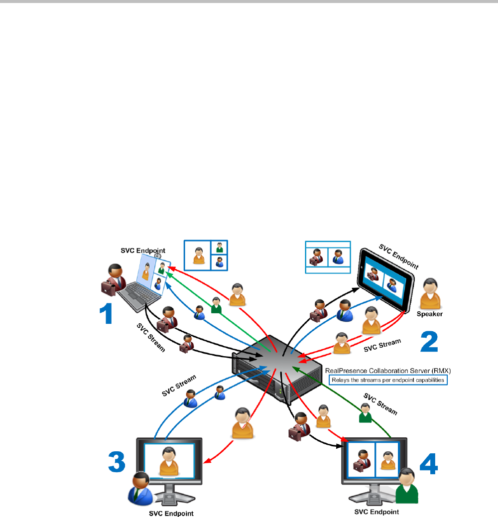
Chapter 2-Conference Profiles
Polycom, Inc. 2-9
SVC-based Conferencing
The SVC-Based conferencing mode provides video without transcoding by the MCU, hence
requiring less video resources while providing better error resiliency and lower latency.
Using the SVC video protocol, SVC conferences provide video bit streams at different
resolutions, frame rates and line rates to SVC-enabled endpoints with various display
capabilities and layout configurations.
In the SVC-based conference, each SVC-enabled endpoint transmits multiple bit streams,
called simulcasting, to the Polycom® RealPresence® Collaboration Server. Simulcasting
enables each endpoint to transmit at different resolutions and frame rates such as 720p at
30fps, 15fps, and 7.5fps, 360p at 15fps and 7.5fps, and 180p at 7.5fps.
The Polycom SVC-enabled endpoints (such as Polycom® RealPresence® Desktop and
Polycom® RealPresence® Mobile) compose the layout according to their layout settings and
video capabilities. This enables the MCU to send or relay the selected video streams to each
endpoint without processing the video streams and sending the composite video layout to
the endpoints.
-
Figure 2-2 SVC video streams and Layouts
The video streams displayed in the conference layout on each endpoint is obtained from the
different streams received from each of the endpoints displayed in the layout. Depending on
the size of the video cell in the configured layout, the endpoint requests the video stream in
the required resolution from the RealPresence Collaboration Server. The higher the display
quality and size, the higher the requested resolution will be sent to the endpoint. The
endpoint creates the displayed layout from the different video streams it receives.

Polycom® RealPresence Collaboration ServerVirtual Edition Administrator’s Guide
2-10 Polycom, Inc.
For instance, an SVC endpoint might want to receive three video streams at different frame
rates and resolutions, and create a conference layout with the received video streams. Each
SVC-enabled endpoint sends encoded SVC bit streams to the MCU to relay to the other
SVC-enabled endpoints in the conference.
The endpoints encode the video in multiple resolutions and decodes the multiple video
input streams.
For example:
RealPresence mobile client (2) will transmit two resolutions; one that is suited for
RealPresence Desktop client (3) and a second that is suited for two other endpoints:
RealPresence Desktop client (4) and (1).
RealPresence Desktop client (1) transmits two resolutions; one that is suited for
RealPresence Mobile client (2) and a second that is suited for RealPresence Desktop
client (4).
The MCU determines which of the incoming resolutions to send to each endpoint. It does
not perform any SVC encoding and decoding, or any transcoding of the video streams. The
RealPresence Collaboration Server functions as the multipoint media relay to the endpoints.
For voice activated selection of the video streams, the RealPresence Collaboration Server
determines which of the incoming bit streams to send to each endpoint.
Advantages of SVC Conferencing
SVC increases the scalability of video networks and enables mass desktop video
deployments. Some of the advantages of SVC conferencing are:
• Offers high-resolution video conferencing with low end-to-end latency, improved error
resiliency and higher system capacities.
• Allows the SVC-enabled video endpoints to manage display layouts, supporting
multiple line rates, resolutions and frame rates.
• The RealPresence Collaboration Server functions as a media relay server providing low
cost production benefits. The RealPresence Collaboration Server reduces bandwidth
usage by only selecting the necessary video stream to be sent to the endpoints.
Guidelines
• SVC conferences are supported only with the following:
—SVC Licensing
—SIP over UDP signaling
—SIP over TLS Signaling
—Polycom SVC-enabled endpoints (Polycom® RealPresence® Desktop, Polycom®
RealPresence® Mobile)
• SVC Only conferences can run on the same MCU as AVC Only conferences.
• End-to-end latency on a local network (same site), is around 200mSec to ensure AV
sync (also known as Lip-sync).
• Dial-out is not available in SVC Only conference.
• Dial-in is available as follows:
—AVC endpoints (participants) can only connect to an AVC conference or Mixed CO
and SVC conference. When dialing into SVC Only conferences they will be
disconnected and the calls fail.

Chapter 2-Conference Profiles
Polycom, Inc. 2-11
—SVC endpoints support both AVC and SVC video protocols.
When dialing into SVC Only conferences, they connect as SVC endpoints.
When dialing into AVC Only conferences, they connect as AVC endpoints. They
cannot connect to an AVC conference using the SVC capabilities.
• SVC endpoints can connect to conferences via Entry Queues, however:
—The Entry Queue and Conference Modes must match - both SVC Only or both
Mixed.
—Both the Entry Queue and the Conference must have the same line rate.
• SVC endpoints cannot be moved between conferences.
• Content is supported in H.264 (AVC).
—Only the H.264 Cascade and SVC Optimized option is supported.
—LPR and DBA are not supported for SVC content sharing.
• In SVC Only conferences and Mixed CP and SVC conferences, Auto Layout is the
default and the layout display for SVC endpoints is controlled from the endpoint
application.
• Site names display on SVC endpoints is controlled from the SVC endpoints.
• When DMA is part of the solution, the DMA is used as the SIP proxy and the SVC
endpoint subscribes to DMA for call control. If a DMA is not part of the solution, the
SVC endpoint dial directly to the Collaboration Server using IP addresses is the SIP
dialing strings.
• When Hot backup is enabled, all the conferences are created on the Slave MCU.
• When Hot Backup is activated and the Slave MCU becomes the Master MCU:
— All AVC endpoints will be reconnected to the AVC conferences. SVC endpoints
connected to AVC conferences using their AVC capabilities will be reconnected to
their AVC conferences.
—SVC endpoints cannot be reconnected to their SVC Only conferences as dial-out is
not supported for SVC endpoints. These endpoints will have to manually
reconnect to their SVC conferences.
• Cascading between SVC Only conferences or between AVC and SVC Only conferences
is not supported.
• The following functionality and features are not supported during SVC Only
conferences:
—FECC
—Skins. The video cells are displayed on the endpoint’s default background.
—Conference Gathering phase
—Password protected conferences as DTMF input for passwords cannot be
processed
—Manual selection of video layout
—Recording of SVC Only conferences
—Text messaging using Message Overlay

Polycom® RealPresence Collaboration ServerVirtual Edition Administrator’s Guide
2-12 Polycom, Inc.
MCU Supported Resolutions for SVC Conferencing
The MCU automatically selects the resolution and frame rate according to the conference
line rate. Table 2-3 details the maximum resolution and frame rates supported by the MCU
for each conference line rate. The actual video rate, resolution and frame rates displayed on
each endpoints is determined by the endpoint’s capabilities.:
Default Profile Settings in SVC Only Conferencing Mode
The Collaboration Server is shipped with a default Conference Profile for SVC Only
conferences which allows users to immediately start standard ongoing SVC Only
conferences. These are also the default settings when creating a new Profile.
The default
settings are as follows
:
Table 2-3 SVC Conferencing - Maximum Supported Resolutions per Simulcast Stream
Conference Line Rate
(kbps) Profile Maximum
Resolution
Max. Frame
Rate (fps)
Audio Rate
(kbps)
1472 - 2048 High Profile 720p 30fps 48
1024 - 1472 High Profile 720p 15fps 48
768 - 1024 High Profile 720p 15fps 48
512 - 768 High Profile 360p 30fps 48
256 - 512 Base Profile 180p 15fps 48
192 - 256 Base Profile 180p 30fps 48
128 - 192 Base Profile 180p 15fps 48
Table 2-4 Default SVC Only Conference Profile Settings
Setting Value
Profile Name Factory_SVC_Video_Profile
Line Rate 1920Kbps
Operator Conference Not supported
Encryption Disabled
Packet Loss Compensation (LPR and
DBA)
Not supported
Auto Terminate •After last participant quits - Enabled
•When last participant remains - Disabled
Auto Redialing Not supported
Exclusive Content Mode Disabled

Chapter 2-Conference Profiles
Polycom, Inc. 2-13
Mixed CP and SVC Conferencing
In a mixed CP (AVC) and SVC conference, AVC-based endpoints and SVC-enabled
endpoints can be supported in the same conference.
In a mixed CP (AVC) and SVC conference, SVC endpoints transmit multiple resolutions and
temporal layers to the RealPresence Collaboration Server like the SVC-based conferences,
while AVC endpoints, for example, send only one H.264 AVC video stream to the
Collaboration Server. Other endpoints (also referred to as AVC endpoints as opposed to
SVC endpoints) can send different video protocols, such as H.263. The Collaboration Server
relays SVC-decoded video bit streams to the SVC-enabled endpoints in the conference
according to their display capabilities. This enables the video conference layouts to be
automatically assembled by the endpoint. AVC endpoints connected to the conference send
a single H.264 AVC video bit stream to the Collaboration Server, which is then transcoded
to SVC video streams. SVC-enabled endpoints receive the AVC converted video bit streams
through the Collaboration Server from the AVC endpoints as a single SVC video bit stream.
Alternatively, AVC endpoints receive a single video bit stream with the defined video
conference layout from the Collaboration Server. In this mixed mode conferencing, both
SVC and AVC endpoints in the conference receive the same CP layout.
Enable FECC Disabled
Video Quality Sharpness
Maximum Resolution Auto
Content Settings Graphics
Content Protocol H.264 Cascading and SVC Optimized
Presentation Mode Not applicable
Same Layout Not applicable
Lecturer View Switching Not applicable
Auto Scan Interval Not applicable
Auto Layout Enabled (Only available option)
Mute participants except the lecturer Not applicable
IVR Name Conference IVR Service
Network Services - SIP Registration Disabled
Network Services - Accept Calls Enabled
Table 2-4 Default SVC Only Conference Profile Settings (Continued)
Setting Value
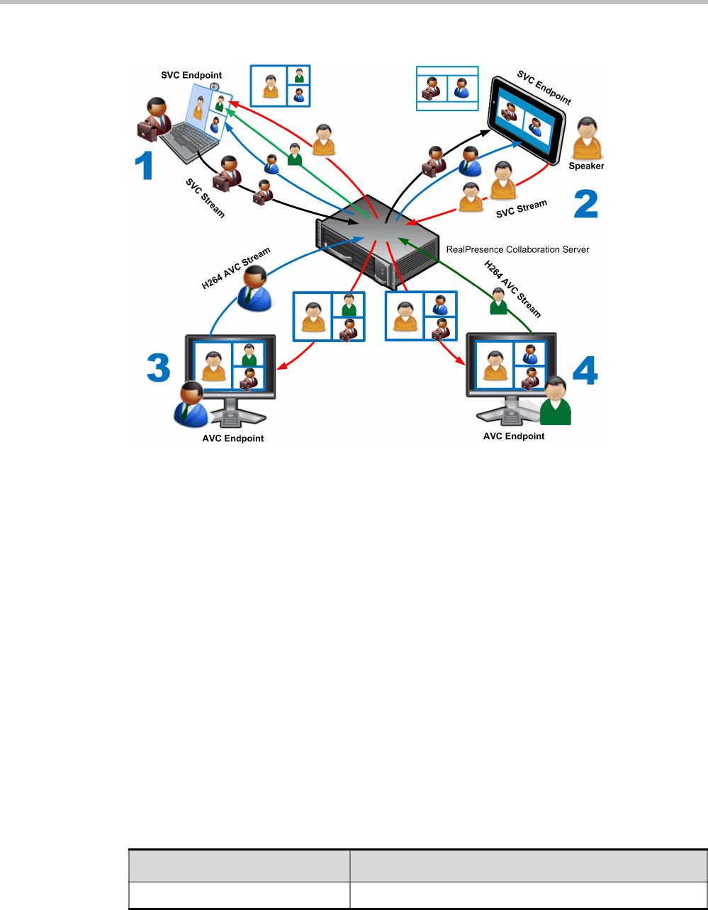
Polycom® RealPresence Collaboration ServerVirtual Edition Administrator’s Guide
2-14 Polycom, Inc.
The following diagram illustrates an example of a mixed CP and SVC conferencing mode:
In this example, an SVC endpoint (1) receives three video streams at different frame rates
and resolutions, and creates the conference layout with the received video streams. The
video bit stream that the SVC endpoint receives from the AVC endpoint (3) is transcoded in
the Collaboration Server and then encoded into an SVC bit stream in the required
resolution.
Alternatively, an AVC endpoint (4) sends a single resolution video stream to the
Collaboration Server. The Collaboration Server first converts the SVC bit stream into AVC,
then transcodes the video received from the other endpoints to the required resolution. The
Collaboration Server composes the video layout for the AVC endpoint and sends a single
resolution video stream with the video layout to the participant. In the displayed example,
the Collaboration Server creates different video layouts for each AVC endpoint.
Default Profile Settings in a Mixed CP and SVC Conferencing Mode
The Collaboration Server is shipped with a default Conference Profile (CP and SVC) for mixed
CP and SVC conferences which enables users to immediately start a standard ongoing
mixed CP and SVC conference. These are also the default settings when creating a new
Profile. (During mixed SVC & CP conferences, PSTN (Audio Only) calls are supported.)
Dial-out is not available in Mixed CP and SVC conferences.
The default settings are as follows
:
Table 2-5 Default Mixed CP and SVC Conference Profile Settings
Setting Value
Profile Name Factory_Mix_SVC_CP_Video_Profile

Chapter 2-Conference Profiles
Polycom, Inc. 2-15
Line Rate 1920Kbps
Operator Conference Disabled
Encryption Enabled
Packet Loss Compensation (LPR
and DBA)
Enabled for AVC participants only
Auto Terminate •After last participant quits - Enabled
•When last participant remains - Disabled
Auto Redialing Disabled
Font for text over video Enabled for AVC participants only
Exclusive Content Mode Disabled
Enable FECC Enabled
Video Quality Sharpness
Maximum Resolution Auto
Content Settings Graphics
Content Protocol H.264 Cascade and SVC Optimized
Presentation Mode Disabled
Same Layout Enabled
Lecturer View Switching Disabled
Auto Scan Interval Disabled
Auto Layout Enabled
Mute participants except the lecturer Disabled
Skin Classic (for AVC participants)
IVR Name Conference IVR Service
Recording Enabled
Site Names display Enabled for AVC participants only
Network Services - SIP Registration Disabled
Network Services - Accept Calls Enabled
Network quality indication Enabled for AVC participants only
Table 2-5 Default Mixed CP and SVC Conference Profile Settings (Continued)
Setting Value

Polycom® RealPresence Collaboration ServerVirtual Edition Administrator’s Guide
2-16 Polycom, Inc.
This Profile is automatically assigned to the following conferencing entities:
Resource Capacities for Mixed CP and SVC Conferences
In a mixed CP and SVC conference, video resources are allocated according to the MCU
type and the translation pools (AVC to SVC and SVC to AVC) used to convert video
streams. Translation pools are dynamically allocated, when the conference becomes a mixed
CP and SVC conference; resources are not released when the conference stops being a mixed
CP and SVC conference. The translation pools send one SVC to AVC stream with a
resolution of 360p, two AVC to SVC streams with a resolution of 360p and 180p for AVC
HD endpoints, and one video stream with a resolution of 180p for AVC SD endpoints.
When a video stream with a resolution of 360p is not available, a video stream with a
resolution of 180p is sent instead.
Translations between different endpoints can be done without using the highest resolution,
thus saving translation resources. CP video layouts in mixed CP and SVC conferences
support the standard resolutions as in normal CP conferences.
Taking these factors into consideration and the type of MCU deployed in the environment,
the resource capacities for a mixed CP and SVC conference can vary.
The following table describes an example of the resource capacity allocations for the
RealPresence Collaboration Server:
Name ID
Meeting Rooms
Maple_Room 1001
Oak_Room 1002
Juniper_Room 1003
Fig_Room 1004
Entry Queue
Default EQ 1000
Table 2-7 Estimated Resource Capacity Allocations
Resource Type Number of Available Ports
Mixed CP and SVC (HD) (Example) 20 AVC
90 SVC
HD720p30 40
SD (@ 30 fps) 40
SVC Only 60
CIF (@ 30 fps) 60
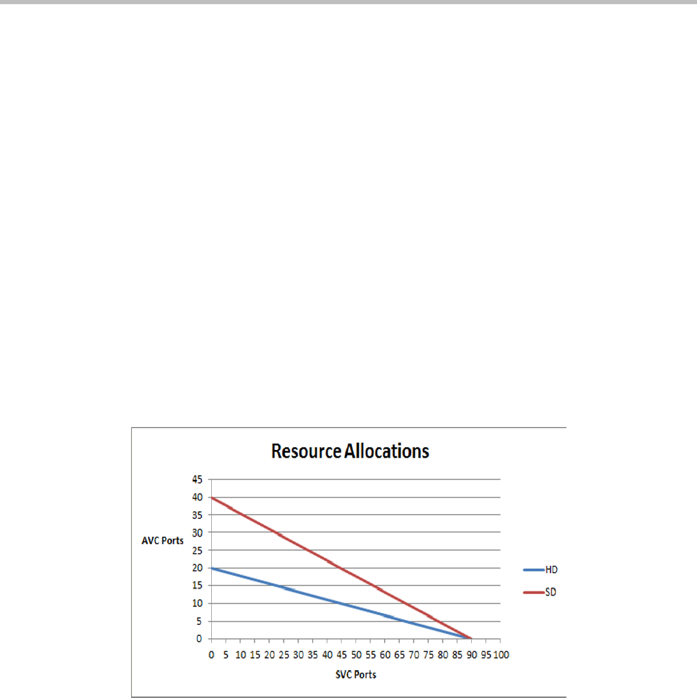
Chapter 2-Conference Profiles
Polycom, Inc. 2-17
The first four resource types in the resource capacity allocations table are endpoints in a CP
only conference or a mixed CP and SVC conference before the actual resource allocations
occur.
In a mixed CP and SVC conference, video resources are used according to the amount of
both AVC and SVC participants in the conference and according to the actual type of the
conference - mixed CP and SVC conferences or CP only conferences. The ratio of resources
in a mixed conference is one AVC HD (720p30) video resource to three SVC video resources,
meaning for each AVC HD video resource, three SVC video resources can be allocated.
In this resource capacity allocations example, the mixed CP and SVC conference can allocate
a combination of AVC and SVC ports depending on the endpoints that are defined in the
actual conference. For example, a conference can be defined as a mixed CP and SVC
conference but will only allocate resources as a mixed conference when both AVC and SVC
endpoints join the conference. When there are only one resource type of endpoints
participating in the conference, such as AVC or SVC, the resource allocations are assigned
according to the type of endpoint. For instance, a mixed CP and SVC conference with HD
endpoints assigned, can have 60 or 120 ports allocated depending on the server
configuration. When an SVC endpoint joins the conference, the conference becomes an
actual mixed conference and the resource allocations are divided between the AVC and SVC
endpoints. The Resource Report will reflect this by showing an increase in the resource
usage.
The following diagram illustrates the amount of AVC to SVC port resources that are used in
an actual mixed CP and SVC conference:
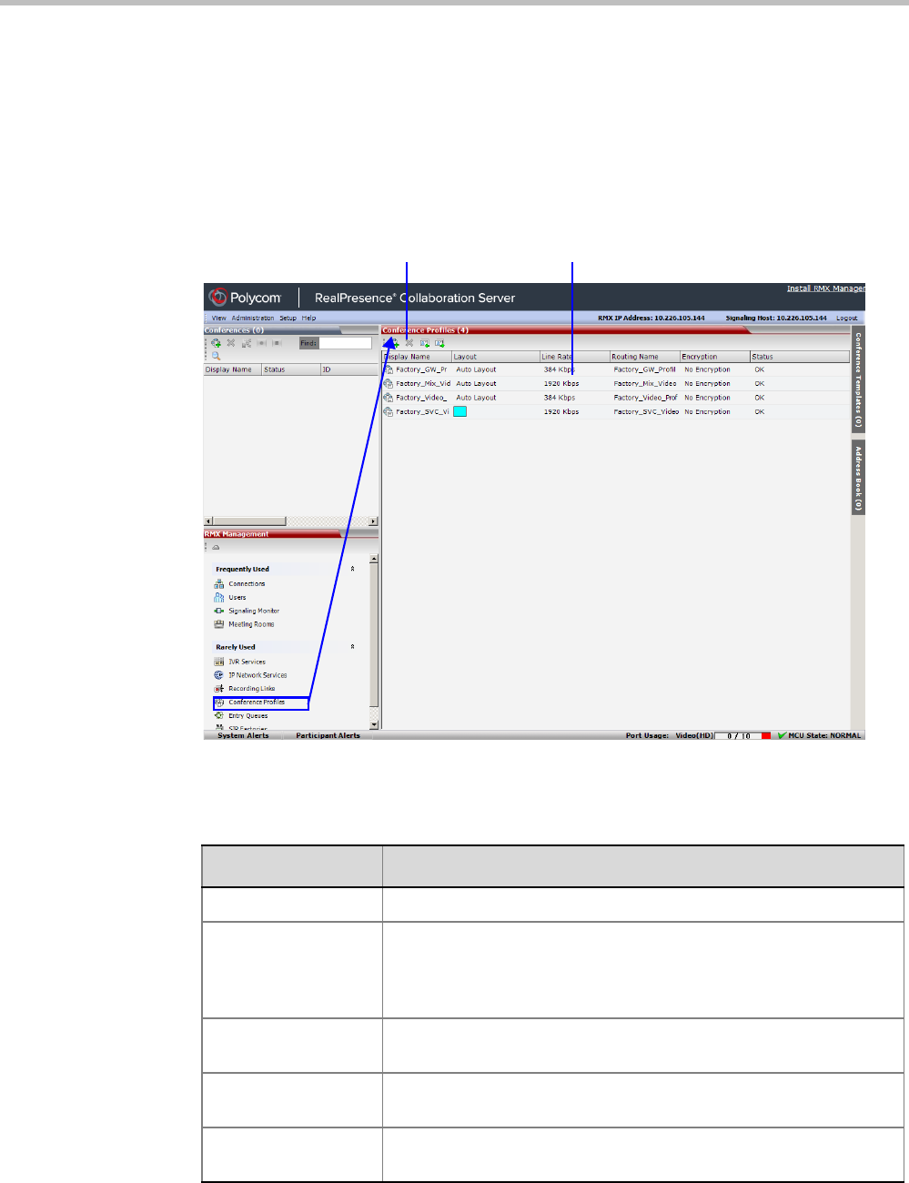
Polycom® RealPresence Collaboration ServerVirtual Edition Administrator’s Guide
2-18 Polycom, Inc.
Viewing Profiles
Conference Profiles are listed in the Conference Profiles list pane.
To list Conference Profiles:
1In the RealPresence Collaboration Server Management pane, expand the Rarely Used list.
2Click the Conference Profiles button.
The Conference Profiles are displayed in the List pane.
The
number of the currently defined Conference Profiles appears in the title of the list pane.
The following Conference Profile properties are displayed in the List pane:
Profile Toolbar Profile List
Table 2-8 Conference Profiles Pane Columns
Field Description
Name The name of the Conference Profile.
Layout Displays either “Auto Layout” or an icon of the layout selected for the
profile.
For information about video layouts, see Table 2-15 "Video Layout
Options” on page 2-31.
Line Rate The maximum bit rate in kbps at which endpoints can connect to the
conference.
Routing Name Displays the Routing Name defined by the user or automatically
generated by the system.
Encryption Displays if media encryption is enabled for the Profile. For more
information see "Media Encryption” on page 3-26.
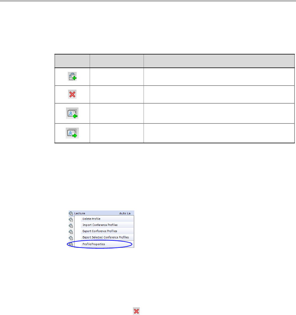
Chapter 2-Conference Profiles
Polycom, Inc. 2-19
Profiles Toolbar
The Profile toolbar provides quick access to the Profile functions:
Modifying an Existing Profile
You can modify any of the Profile’s parameters but you cannot rename the Profile.
To modify the Profile Properties:
1In the Conference Profiles list, double -click the Profile icon or right-click the Profile icon,
and then click Profile Properties.
The Profile Properties - General dialog box opens.
Deleting a Conference Profile
To delete a Conference Profile:
1In the Conference Profiles list, select the Conference Profile you want to delete.
2Click the Delete Profile () button.
or
Right-click the Conference Profile to be deleted and select Delete Profile from the drop-
down menu.
A confirmation dialog box is displayed.
3Click OK in the confirmation dialog box.
4The Conference Profile is deleted.
Table 2-9 Profile Tool bar buttons
Button Button Name Description
New Profile To create a new Profile.
Delete Profile To delete a Profile, click the Profile name and then click this
button.
Import Profile To import Conference Profiles from another MCU in your
environment.
Export Profile To export Conference Profiles to a single XML file that can be
used to import the Conference Profiles on multiple MCUs.

Polycom® RealPresence Collaboration ServerVirtual Edition Administrator’s Guide
2-20 Polycom, Inc.
Defining New Profiles
Profiles are the basis for the definition of all ongoing conferences, Meeting Rooms, Entry
Queues, and Conference Templates and they contain only conference properties.
Conference Profile options differ according to the selected Conferencing Mode and Conference
Type. Profiles can be defined for AVC (Advanced Video Codec) conferencing Mode or SVC
(Scalable Video Codec) conferencing Mode.
AVC Conferencing Mode offers the following Video session types: Continuous Presence
(CP) conferences, Mixed CP and SVC conferences, and a special functional conference -
Operator Conferences in CP mode.
A Conference Profile cannot be deleted if it is being used by Meeting Rooms, Entry Queues, and
SIP Factories. A Profile that is assigned to only one ongoing conference and no other conferencing
entity can be deleted.
In the RealPresence CloudAxis Solution, the Conference Profiles are defined in the RealPresence
DMA system component and should not be defined directly in the RealPresence Collaboration
Server Virtual Edition component.
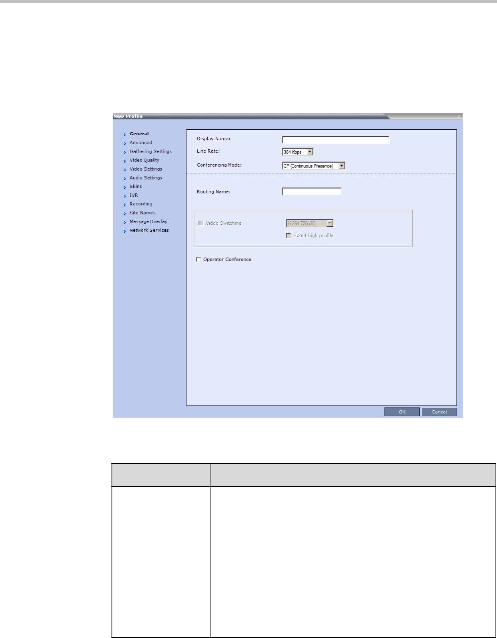
Chapter 2-Conference Profiles
Polycom, Inc. 2-21
Defining AVC CP Conferencing Profiles
To define a new Profile:
1In the RealPresence Collaboration Server Management pane, click Conference Profiles.
2In the Conference Profiles pane, click the New Profile button.
The New Profile – General dialog box opens.
3Define the Profile name and, if required, the Profile - General parameters:
Table 2-10 New AVC CP Profile - General Parameters
Field/Option Description
Display Name Enter a unique Profile name, as follows:
•
English text uses ASCII encoding and can contain the most
characters (length varies according to the field).
•European and Latin text length is approximately half the length of
the maximum.
•Asian text length is approximately one third of the length of the
maximum.
It is recommended to use a name that indicates the Profile type, such
as Operator conference or Video Switching conference.
Note: This is the only parameter that must be defined when creating
a new profile.
Note: This field is displayed in all tabs.

Polycom® RealPresence Collaboration ServerVirtual Edition Administrator’s Guide
2-22 Polycom, Inc.
4Click the Advanced tab.
Line Rate Select the conference bit rate. The line rate
represents the combined
video, audio and Content rate
.
The default setting is 384 Kbps.
Notes:
•This field is displayed in all tabs.
Conferencing Mode For CP conferencing, make sure that CP (Continuous Presence) is
selected to define a CP conference Profile (it is the default option).
Note: This field is displayed in all tabs.
Routing Name Enter the Profile name using ASCII characters set.
The Routing Name can be defined by the user or automatically
generated by the system if no Routing Name is entered as follows:
•If an all ASCII text is entered in Display Name, it is used also as
the Routing Name.
•If any combination of Unicode and ASCII text (or full Unicode text)
is entered in Display Name, the ID (such as Conference ID) is
used as the Routing Name.
Operator Conference Select this option to define the profile of an Operator conference.
For more information, see Chapter 9, “Operator Assistance &
Participant Move” on page 9-1.
Table 2-10 New AVC CP Profile - General Parameters (Continued)
Field/Option Description
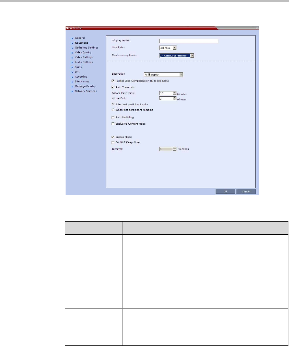
Chapter 2-Conference Profiles
Polycom, Inc. 2-23
The New Profile – Advanced dialog box opens.
5Define the following parameters:
Table 2-11 New AVC CP Profile - Advanced Parameters
Field/Option Description
Encryption Select the Encryption option for the conference:
•Encrypt All - Encryption is enabled for the conference and all
conference participants must be encrypted.
•No Encryption - Encryption is disabled for the conference.
•Encrypt when Possible - enables the negotiation between the
MCU and the endpoints and let the MCU connect the participants
according to their capabilities, where encryption is the preferred
setting. For connection guidelines see "Mixing Encrypted and
Non-encrypted Endpoints in one Conference” on page 3-27.
For more information, see "Media Encryption” on page 3-26.
LPR When selected (default for CP conferences), Lost Packet Recovery
creates additional packets that contain recovery information used to
reconstruct packets that are lost during transmission.
For more information, see "Packet Loss Compensation (LPR and
DBA) AVC CP Conferences” on page 3-34.

Polycom® RealPresence Collaboration ServerVirtual Edition Administrator’s Guide
2-24 Polycom, Inc.
Auto Terminate When selected (default), the conference automatically ends when the
termination conditions are met:
Before First Joins — No participant has connected to a conference
during the n minutes after it started. Default idle time is 10 minutes.
At the End - After Last Quits — All the participants have
disconnected from the conference and the conference is idle (empty)
for the predefined time period. Default idle time is 1 minute.
At the End - When Last Participant Remains — Only one
participant is still connected to the conference for the predefined time
period (excluding the recording link which is not considered a
participant when this option is selected).
Note: The selection of this option is automatically cleared and
disabled when the Operator Conference option is selected. The
Operator conference cannot automatically end unless it is terminated
by the Collaboration Server User.
Auto Redialing The Auto Redialing option instructs the Collaboration Server to
automatically redial H.323 and SIP participants that have been
abnormally disconnected from the conference.
•Auto Redialing is disabled by default.
•Auto Redialing can be enabled or disabled during an ongoing
conference using the Conference Properties – Advanced dialog
box.
•The Collaboration Server will not redial an endpoint that has been
disconnected from the conference by the participant.
•The Collaboration Server will not redial an endpoint that has been
disconnected or deleted from the conference by an operator or
administrator.
Exclusive Content
Mode
Select the Exclusive Content Mode check box to limit the Content
broadcasting to one participant, preventing other participants from
interrupting the Content broadcasting while it is active. For more
details, see "Exclusive Content Mode” on page 3-15.
Enable FECC This option is enabled by default, allowing participants in the
conference to control the zoom and PAN of other endpoints in the
conference via the FECC channel. Clear this check box to disable
this option for all conference participants.
FW NAT Keep Alive The MCU can be configured to send a FW NAT Keep Alive message
at specific Intervals for the RTP, UDP and BFCP channels.
For more information see "FW (Firewall) NAT Keep Alive” on
page 16-79.
Interval If needed, modify the NAT Keep Alive Interval field within the range of
1 - 86400 seconds.For more information see "FW (Firewall) NAT
Keep Alive” on page 16-79.
Table 2-11 New AVC CP Profile - Advanced Parameters (Continued)
Field/Option Description
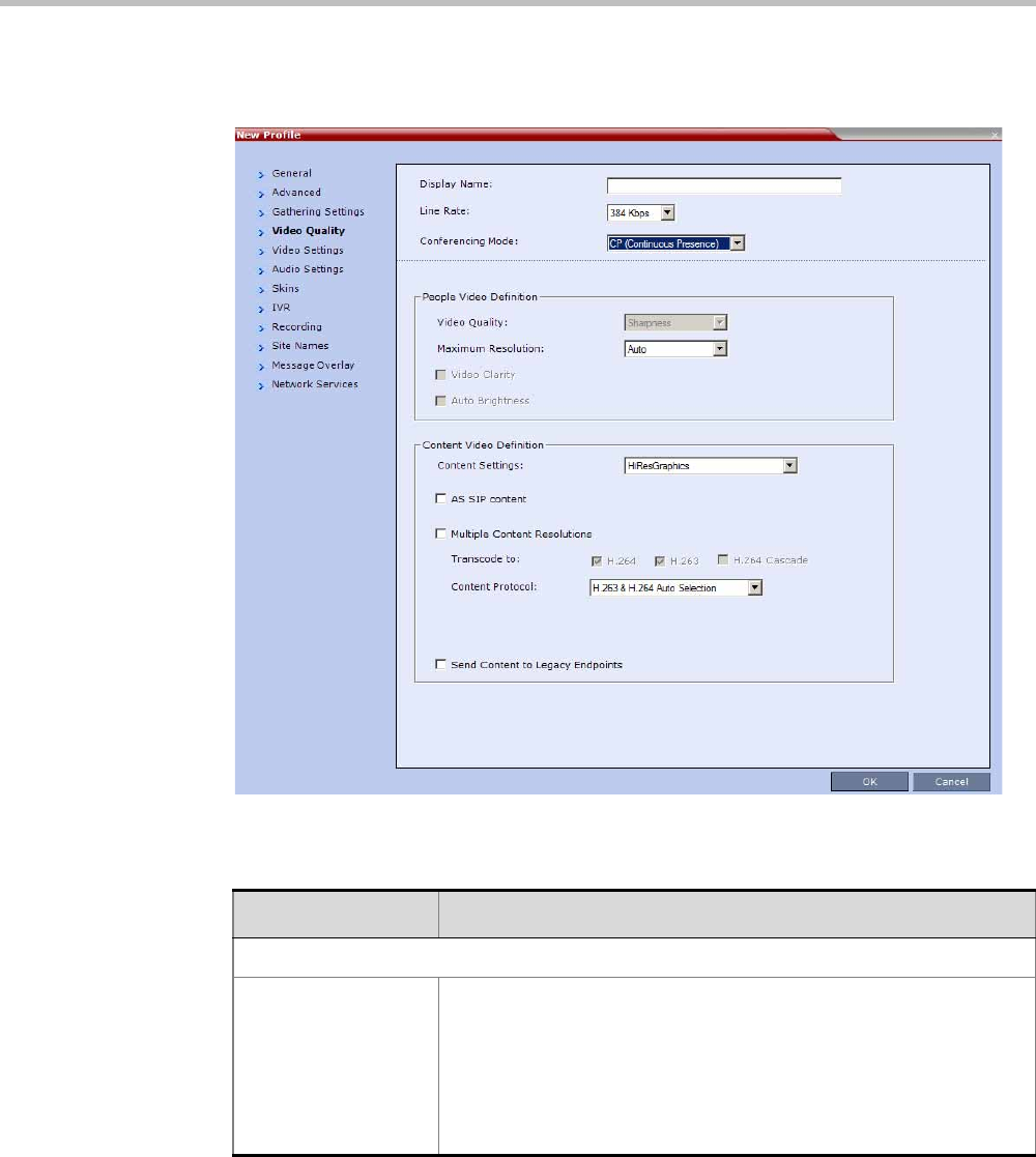
Chapter 2-Conference Profiles
Polycom, Inc. 2-25
6Click the Video Quality tab.
The New Profile – Video Quality dialog box opens.
7Define the following parameters:
Table 2-12 New AVC CP Profile - Video Quality Parameters
Field/Option Description
People Video Definition
Video Quality Sharpness is the only supported content format that supports higher
video resolutions.
Note: When Sharpness is selected as the Video Quality setting in the
conference Profile, the Collaboration Server will send 4CIF (H.263) at
15fps instead of CIF (H.264) at 30fps. For more information, see
"Content Settings” on page 3-7"Video Resolutions in AVC-based CP
Conferencing” on page 4-1.

Polycom® RealPresence Collaboration ServerVirtual Edition Administrator’s Guide
2-26 Polycom, Inc.
Maximum Resolution This setting overrides the Maximum Resolution setting of the
Resolution Configuration dialog box.
The administrator can select one of the following Maximum
Resolution options:
•Auto (default) - The Maximum Resolution remains as selected in
the Resolution Configuration dialog box.
•CIF
•SD
•HD720
Maximum Resolution settings can be monitored in the Profile
Properties - Video Quality and Participant Properties - Advanced
dialog boxes.
Notes:
•The Resolution field in the New Participant - Advanced dialog box
allows Maximum Resolution to be further limited per participant
endpoint.
•The Maximum Resolution settings for conferences and
participants cannot be changed during an ongoing conference.
Content Video Definition
Content Settings Select the transmission mode for the Content channel:
•Graphics — basic mode, intended for normal graphics
•Hi-res Graphics (AVC CP Only) — a higher bit rate intended for
high resolution graphic display
•Live Video (AVC CP Only) — Content channel displays live video
•Customized Content Rate (AVC CP Only) — manual definition of
the Conference Content Rate, mainly for cascading conferences.
Selection of a higher bit rate for the Content results in a lower bit rate
for the people channel.
For a detailed description of each of these options, see "Content
Sharing Parameters in Content Highest Common (Content Video
Switching) Mode” on page 3-6.
AS SIP Content This Content Sharing option is not supported with RealPresence
Collaboration Server Virtual Edition..
Multiple Resolutions This Content Sharing option is not supported with RealPresence
Collaboration Server Virtual Edition.
Table 2-12 New AVC CP Profile - Video Quality Parameters (Continued)
Field/Option Description

Chapter 2-Conference Profiles
Polycom, Inc. 2-27
Content Protocol Select the Content Protocol to be used for content sharing in Highest
Common Content Sharing Mode.
•H.263(AVC CP only)
•Content is shared using the H.263 protocol.
•Use this option when most of the endpoints support H.263 and
some endpoints support H.264.
•H.263 & H.264 Auto Selection (AVC CP only)
•Content is shared using H.263 if a mix of H.263-supporting
and H.264-supporting endpoints are connected.
•Content is shared using H.264 if all connected endpoints have
H.264 capability.
•H.264 Cascade and SVC Optimized
•All Content is shared using the H.264 content protocol and is
optimized for use in Cascaded Conferences.
•H.264 HD (AVC CP only, default)
•Ensures high quality Content when most endpoints support
H.264 and HD Resolutions.
When Multiple Resolutions is selected, this feature is hidden.
For more information, see "Content Protocols” on page 3-8 and
"Defining Content Sharing Parameters for a Conference” on page 3-3.
Content Resolution Select the Content Resolution and frame rate according to the
selected Content Sharing Mode (Highest common Content or Multiple
Resolution Contents) and the video protocol. For more information,
see "Defining Content Sharing Parameters for a Conference” on
page 3-3.
Send Content to
Legacy Endpoints
(CP only)
This Content Sharing option is not supported with RealPresence
Collaboration Server Virtual Edition.
Table 2-12 New AVC CP Profile - Video Quality Parameters (Continued)
Field/Option Description
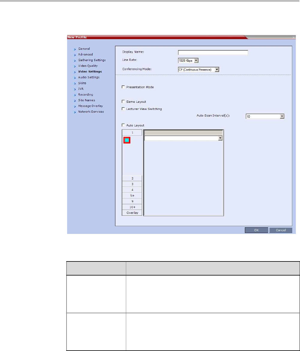
Polycom® RealPresence Collaboration ServerVirtual Edition Administrator’s Guide
2-28 Polycom, Inc.
8Click the Video Settings tab.
The New Profile - Video Settings dialog box opens.
9Define the video display mode and layout using the following parameters:
Table 2-13 New AVC CP Profile - Video Settings Parameters
Field/Option Description
Presentation Mode
(CP only)
Select this option to activate the Presentation Mode. In this mode,
when the current speaker speaks for a predefined time (30 seconds),
the conference changes to Lecture Mode. When another participant
starts talking, the Presentation Mode is cancelled and the conference
returns to the previous video layout.
Same Layout
(CP only)
Select this option to force the selected layout on all participants in a
conference. Displays the same video stream to all participants and
personal selection of the video layout is disabled. In addition, if
participants are forced to a video layout window, they can see
themselves.
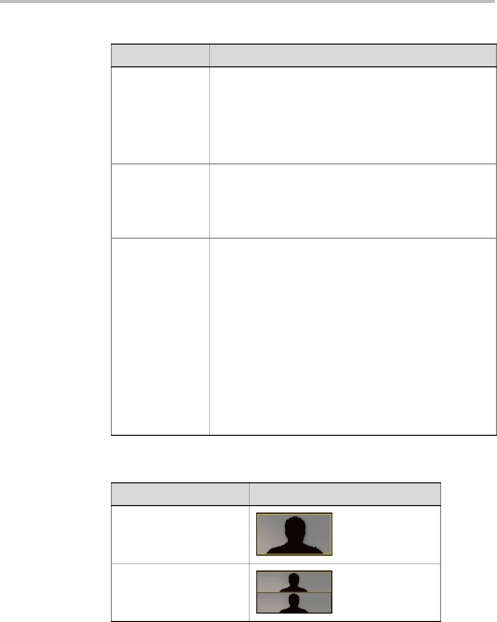
Chapter 2-Conference Profiles
Polycom, Inc. 2-29
Lecture View
Switching
Select this option to enable automatic switching of participants on the
Lecturer’s screen when Lecture Mode is enabled for the conference.
The automatic switching is enabled when the number of participants
exceeds the number of video windows displayed on the Lecturer’s
screen.
Note: Lecture Mode is enabled in the Conference Properties –
Participants tab. For more information, see "Lecture Mode (AVC CP
Only)” on page 3-38.
Auto Scan Interval(s)
(CP only)
Select the time interval, 5 - 300 seconds, that Auto Scan uses to cycle
the display of participants that are not in the conference layout in the
selected cell.
Auto Scan is often used in conjunction with Customized Polling which
allows the cyclic display to be set to a predefined order for a
predefined time period.
Auto Layout
(CP only)
When selected (default), the system automatically selects the
conference layout based on the number of participants currently
connected to the conference. When a new video participant connects
or disconnects, the conference layout automatically changes to reflect
the new number of video participants.
For more information, see Table 2-14 "Auto Layout – Default Layouts
in CP Conferences” on page 2-29.
Clear this selection to manually select a layout for the conference.
The default Auto Layout settings can be customized by modifying
default Auto Layout system flags in the System Configuration file. For
more information see, "Auto Layout Configuration” on page 20-34.
Note: In some cases, the default layout automatically selected for the
conference contains more cells than the number of connected
participants, resulting in an empty cell. For example, if the number of
connected participants is 4, the default layout is 2x2, but as only 3
participants are displayed in the layout (the participants do not see
themselves), one cell is empty.
Table 2-13 New AVC CP Profile - Video Settings Parameters (Continued)
Field/Option Description
Table 2-14 Auto Layout – Default Layouts in CP Conferences
Number of Video Participants Auto Layout Default Settings
0–2
3
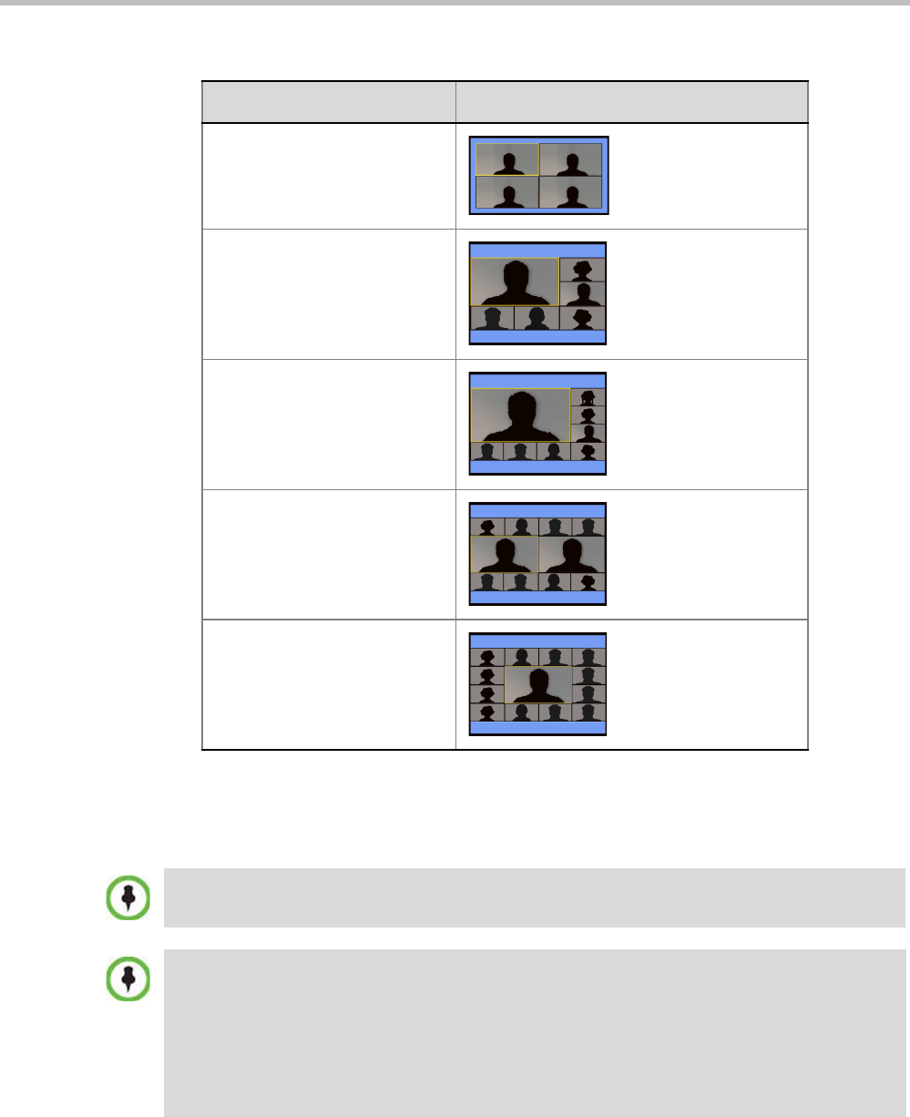
Polycom® RealPresence Collaboration ServerVirtual Edition Administrator’s Guide
2-30 Polycom, Inc.
In layout 2+8, the two central windows display the last two speakers in the conference:
the current speaker and the “previous” speaker. To minimize the changes in the layout,
when a new speaker is identified the “previous” speaker is replaced by the new speaker
while the current speaker remains in his/her window.
4–5
6–7
8-10
11
12+
Table 2-14 Auto Layout – Default Layouts in CP Conferences (Continued)
Number of Video Participants Auto Layout Default Settings
The Collaboration Server supports the VUI addition to the H.264 protocol for endpoints that transmit
wide video (16:9) in standard 4SIF resolution.
When there is a change of speaker in a Continuous Presence conference, the transition is set by
default to fade in the current speaker while fading out the previous speaker.
To make this transition visually pleasant, fading in the current speaker while fading out the previous
speaker is done over a period of 500 milliseconds.
The Fade In / Fade Out feature can be disabled by adding a new flag to the System Configuration.
The Value of the new flag must be: FADE_IN_FADE_OUT=NO.
For more information about System Flags, see the Polycom® RealPresence Collaboration Server
Virtual Edition Administrator’s Guide, "Modifying System Flags” on page 20-1.
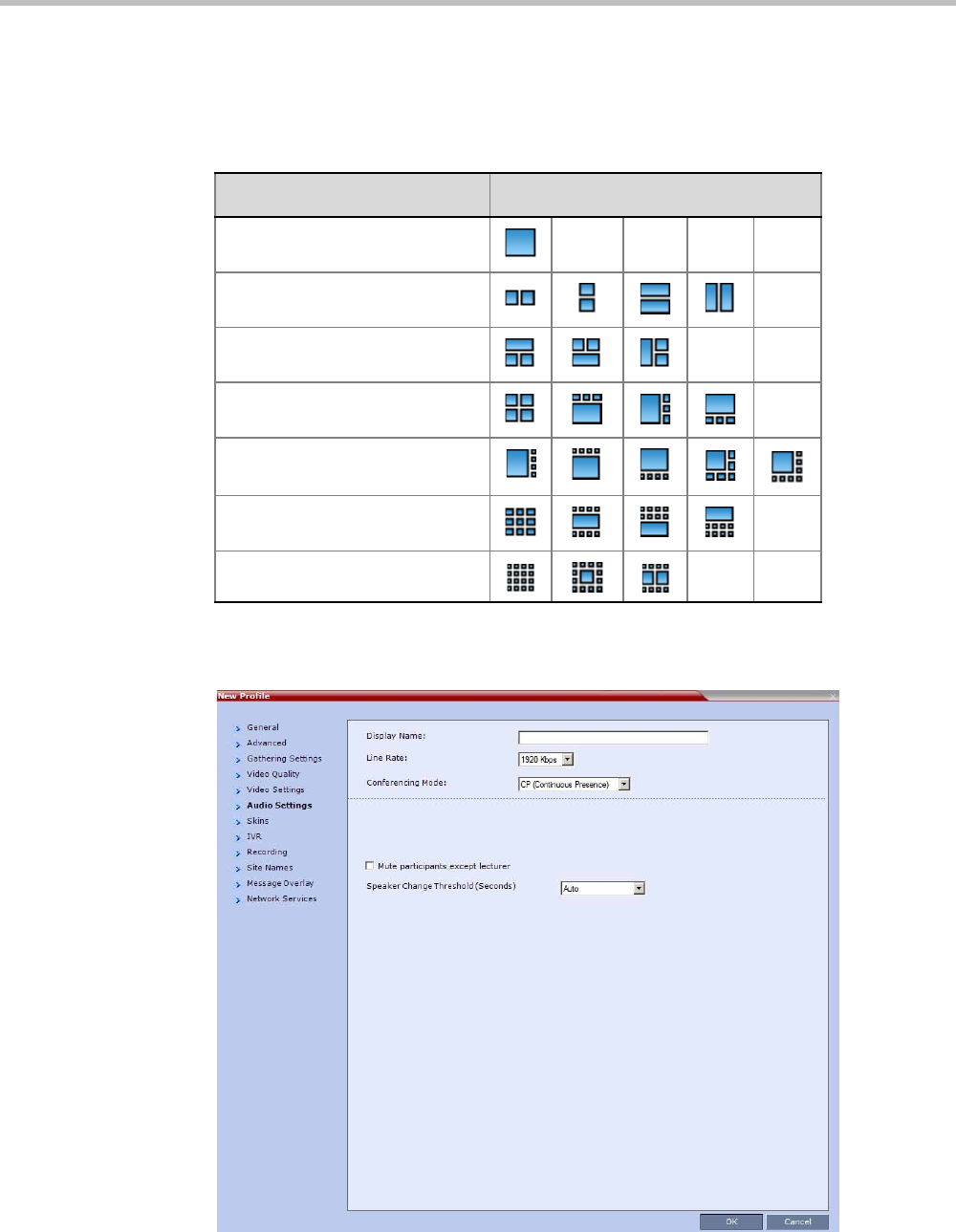
Chapter 2-Conference Profiles
Polycom, Inc. 2-31
10 To select the Video Layout for the conference, click the required number of windows
from the layouts bar and then select the windows array. The selected layout is
displayed in the Video Layout pane.
11 Click the Audio Settings tab.
The New Profile - Audio Settings dialog box opens.
Table 2-15 Video Layout Options
Number of Video Windows Available Video Layouts
1
2
3
4
5+
9
10+

Polycom® RealPresence Collaboration ServerVirtual Edition Administrator’s Guide
2-32 Polycom, Inc.
12 Define the following parameters:
Table 2-16 New AVC CP Profile - Audio Settings Parameters
Field/Option Description
Mute participant
except lecturer
When the Mute Participants Except Lecturer option is enabled, the
audio of all participants in the conference except for the lecturer can
be automatically muted upon connection to the conference. This
prevents other conference participants from accidentally interrupting
the lecture, or from a noisy participant affecting the audio quality of the
entire conference. Muted participants cannot unmute themselves
unless they are unmuted from the Collaboration Server Web Client/
RMX Manager.
You can enable or disable this option during the ongoing conference.
Notes:
•When enabled, the mute indicator on the participant endpoints are
not visible because the mute participants was initiated by the
MCU. Therefore, it is recommended to inform the participants that
their audio is muted by using the Closed Caption or Message
Overlay functions.
In the Collaboration Server Web Client/RMX Manager the mute by
MCU indicator is listed for each muted participant in the Audio
column in the Participants pane.
•The Mute Participants Except Lecturer option can be disabled
during an ongoing conference, thereby unmuting all the
participants in the conference.
•If the endpoint of the designated lecturer is muted when the
lecturer connects to the conference, the lecturer remains muted
until the endpoint has been unmuted.
•When you replace a lecturer, the MCU automatically mutes the
previous lecturer and unmutes the new lecturer.
Mute participant
except lecturer
(continued)
•When you disconnect a lecturer from the conference or the
lecturer leaves the conference, all participants remain muted but
are able to view participants in regular video layout until the you
disable the Mute Participants Except Lecturer option.
•A participant can override the Mute Participants Except Lecturer
option by activating the Mute All Except Me option using the
appropriate DTMF code, provided the participant has authorization
for this operation in the IVR Services. The lecturer audio is muted
and the participant audio is unmuted. You can reactivate the Mute
Participants Except Lecturer option after a participant has
previously activated the Mute All Except Me option. The
participant is muted and the lecturer, if designated, is unmuted.
•In cascaded conferences, all participants (including the link
participants) are muted. Only the lecturer is not muted.

Chapter 2-Conference Profiles
Polycom, Inc. 2-33
13 Click the Skins tab to modify the background and frames.
The New Profile - Skins dialog box opens.
14 Select one of the Skin options.
15 Click IVR tab.
Speaker Change
Threshold
The Speaker Change Threshold is the amount of time a participant
must speak continuously before becoming the speaker. When
defining or editing a conference profile, you can define the Speaker
Change Threshold.
Select the desired threshold:
•Auto (Default, 3 seconds)
•1.5 seconds
•3 seconds
•5 seconds
Table 2-16 New AVC CP Profile - Audio Settings Parameters (Continued)
Field/Option Description
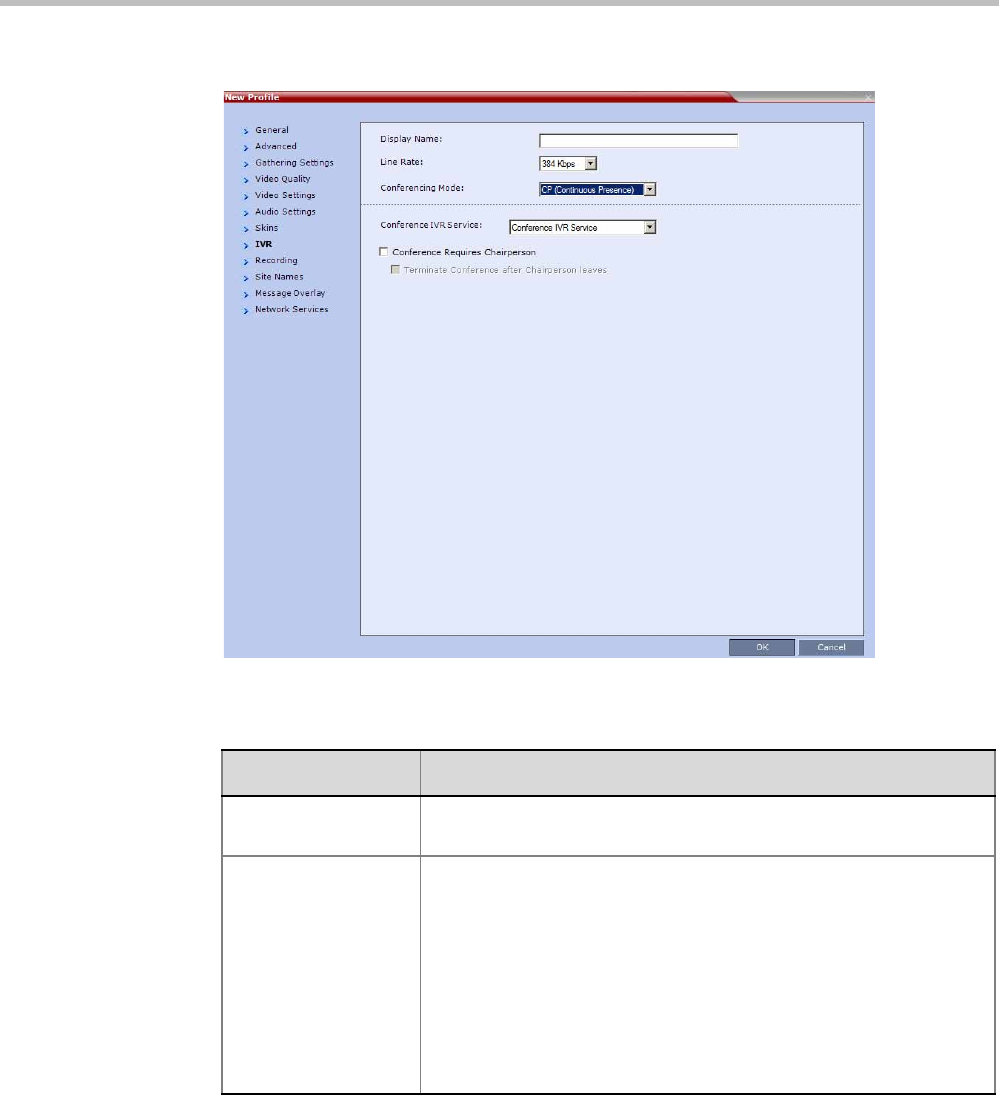
Polycom® RealPresence Collaboration ServerVirtual Edition Administrator’s Guide
2-34 Polycom, Inc.
The New Profile - IVR dialog box opens.
16 If required, set the following parameters:
Table 2-17 New AVC CP Profile - IVR Parameters
Field/Option Description
Conference IVR
Service
The default conference IVR Service is selected. You can select
another conference IVR Service if required.
Conference Requires
Chairperson
Select this option to allow the conference to start only when the
chairperson connects to the conference and to automatically
terminate the conference when the chairperson exits. Participants
who connect to the conference before the chairperson are placed on
Hold and hear background music (and see the Welcome video slide).
Once the conference is activated, the participants are automatically
connected to the conference.
When the check box is cleared, the conference starts when the first
participant connects to it and ends at the predefined time or according
to the Auto Terminate rules when enabled.
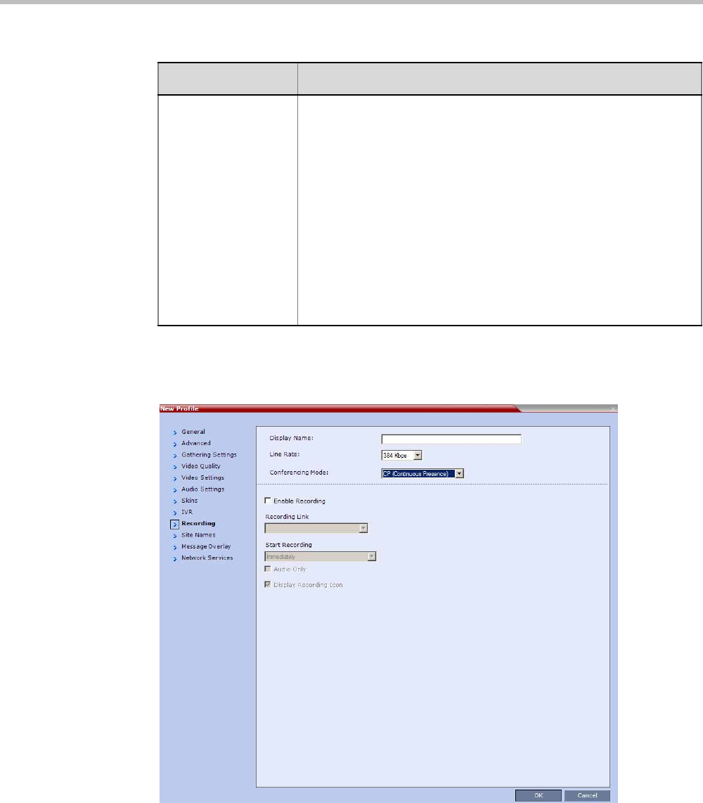
Chapter 2-Conference Profiles
Polycom, Inc. 2-35
17 Optional. Click the Recording tab to enable conference recording with Polycom
RSS 2000/4000.
The New Profile - Recording tab opens.
Terminate conference
after chairperson
leaves
Select this check box to automatically terminate the conference after
the chairperson leaves. When the chairperson leaves, the
“Chairperson Has Left” IVR message is played to all participants, at
which point the conference terminates. This way an operator does not
need to monitor a conference to know when to terminate it manually.
If there is a single chairperson in the conference who is changed to a
regular participant the conference will be terminated as if the
chairperson left. If there is more than one chairperson, then changing
one chairperson to a regular participant will not terminate the
conference. It is therefore recommended that before changing a
single chairperson to regular participant, another participant first be
changed to chairperson.
Note: The Chairperson can be either an AVC-enabled or SVC-
enabled endpoint.
Table 2-17 New AVC CP Profile - IVR Parameters (Continued)
Field/Option Description
Polycom® RealPresence Collaboration ServerVirtual Edition Administrator’s Guide
2-36 Polycom, Inc.
18 Define the following parameters:
Table 2-18 New AVC CP Profile - Recording Parameters
Parameter Description
Enable Recording Select this check box to enable the Recording settings. If no
Recording Links are found an error message is displayed.
Recording Link Select the Recording Link to be used for conference recording.
Recording Links defined on the Collaboration Server can be given a
descriptive name and can be associated with a Virtual Recording
Room (VRR) saved on the Polycom® RSS™ 4000 Version 6.0
Recording and Streaming Server (RSS). For more information see
"Recording Conferences” on page 13-1.
Start Recording Select one of the following:
•Immediately – conference recording is automatically started upon
connection of the first participant.
•Upon Request – the operator or chairperson must initiate the
recording (manual).
Display Recording
Icon
This option is automatically selected to display a Recording Indication
to all conference participants informing them that the conference is
being recorded.
The Recording participant does not support H.264 High Profile. If recording a conference that is set
to H.264 High Profile, the Recording participant connects as Audio Only and records the conference
Audio.
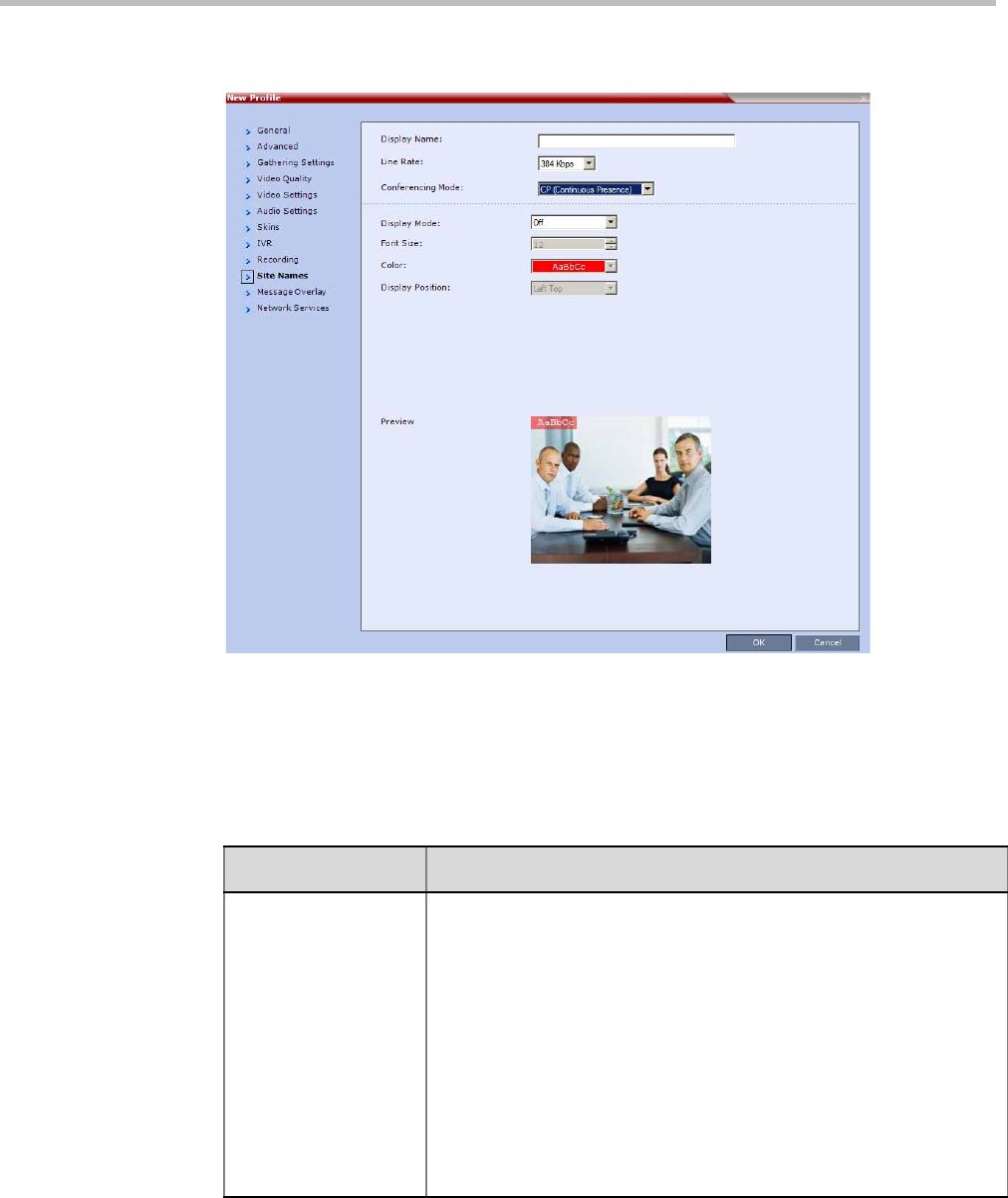
Chapter 2-Conference Profiles
Polycom, Inc. 2-37
19 Click the Site Names tab to display the Site Names dialog box.
Using the Site Name dialog box, you can control the display of the site names by
defining the font, size, color, background color and transparency and position within
the Video Window. For a detailed description of the site names options see "Site Names
Definition” on page 2-55.
Define the following parameters:
Table 2-19 New AVC CP Profile - Site Names Parameters
Field Description
Display Mode Select the display mode for the site names:
•Auto - Display the Site Names for 10 seconds whenever the Video
Layout changes.
•On - Display the Site Names for the duration of the conference.
•Off (default) - Do not display the Site Names.
Note:
The Display Mode field is grayed and disabled if Video Switching mode
is selected in the Profile - General tab.
If Display Mode is Off, all other fields in this tab are grayed and
disabled.
Selecting Off enables Video Switching for selection in the Profile -
General tab (if the conference is not already ongoing).
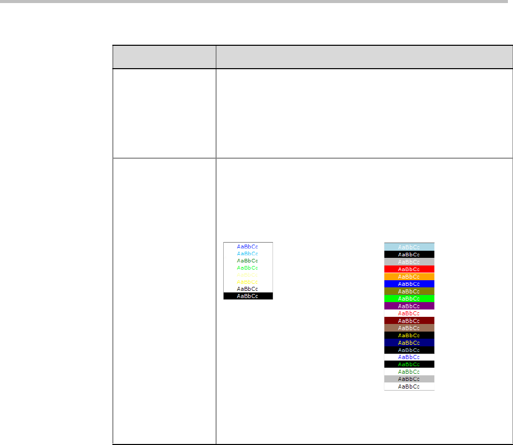
Polycom® RealPresence Collaboration ServerVirtual Edition Administrator’s Guide
2-38 Polycom, Inc.
Font Size Click the arrows to adjust the font size (in points) for the Site Names
display.
Range: 9 - 32 points
Default: 12
Note: Choose a Font Size that is suitable for viewing at the
conference’s video resolution. For example, if the resolution is CIF, a
larger Font Size should be selected for easier viewing.
Background Color Select the color of the Site Names display text.
The color and background for Site Names display text is dependent on
whether a Plain Skin or a Picture Skin was selected for the conference
in the Profile - Skins tab.
The choices are:
Note: Choose a Background Color combination that is suitable for
viewing at the conference’s video resolution. At low resolutions, it is
recommended to select brighter colors as dark colors may not provide
for optimal viewing.
Table 2-19 New AVC CP Profile - Site Names Parameters (Continued)
Field Description
Plain Skin Picture Skin
Default:
White Text
No Background
(For contrast, no
background is shown as
black when the text is
white.)
Default:
White Text
Red Background
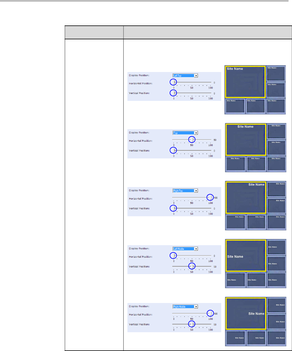
Chapter 2-Conference Profiles
Polycom, Inc. 2-39
Display Position Select the pre-set position for the display of the Site Names.
Selection Site Names Position
LeftTop (Default)
To p
RightTop
LeftMiddle
RightMiddle
Table 2-19 New AVC CP Profile - Site Names Parameters (Continued)
Field Description
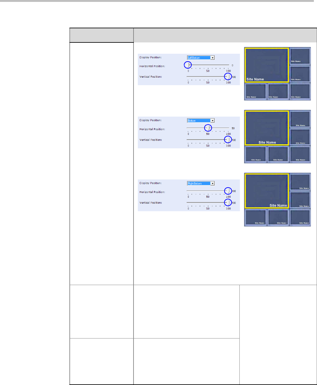
Polycom® RealPresence Collaboration ServerVirtual Edition Administrator’s Guide
2-40 Polycom, Inc.
Display Position
(cont.)
LeftBottom
Bottom
RightBottom
Custom The current Site Names
display position becomes
the initial position for Site
Names position
adjustments using the
Horizontal and Vertical
Position sliders.
Horizontal Position Move the slider to the left to move the
horizontal position of the Site Names to
the left within the Video Windows.
Move the slider to the right to adjust
the horizontal position of the Site
Names to the right within the Video
Windows.
Note: Use of these sliders
will set the Display Position
selection to Custom.
Vertical Position Move the slider to the left to move the
vertical position of the Site Names
upward within the Video Windows.
Move the slider to the right to move the
vertical position of the Site Names
downward within the Video Windows.
Table 2-19 New AVC CP Profile - Site Names Parameters (Continued)
Field Description
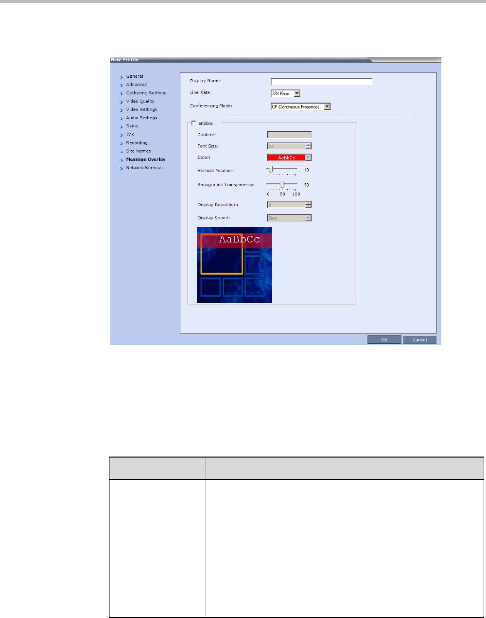
Chapter 2-Conference Profiles
Polycom, Inc. 2-41
20 For CP Conferences only: Click the Message Overlay tab to display the Message
Overlay dialog box.
Message Overlay enables you to send text messages to all participants during ongoing
Continuous Presence conferences.
The text message is seen as part of the in the participant’s video layout on the endpoint
screen or desktop display.
For more details, see "Message Overlay for Text Messaging” on page 2-58.
Define the following fields:
Table 2-20 New AVC CP Profile - Message Overlay Parameters
Field Description
Enable Select this check box to enable Message Overlay. Clear this check
box to disable Message Overlay.
Default: Cleared.
Note:
•The Message Overlay field is shaded and disabled when Video
Switching mode is selected in the New Profile - General tab. All
other fields in this tab are also disabled.
•Clearing the Enable check box enables Video Switching for
selection in the New Profile - General tab.
•If Message Overlay is selected, the Video Switching check box in
the New Profile - General tab is disabled and cannot be selected.
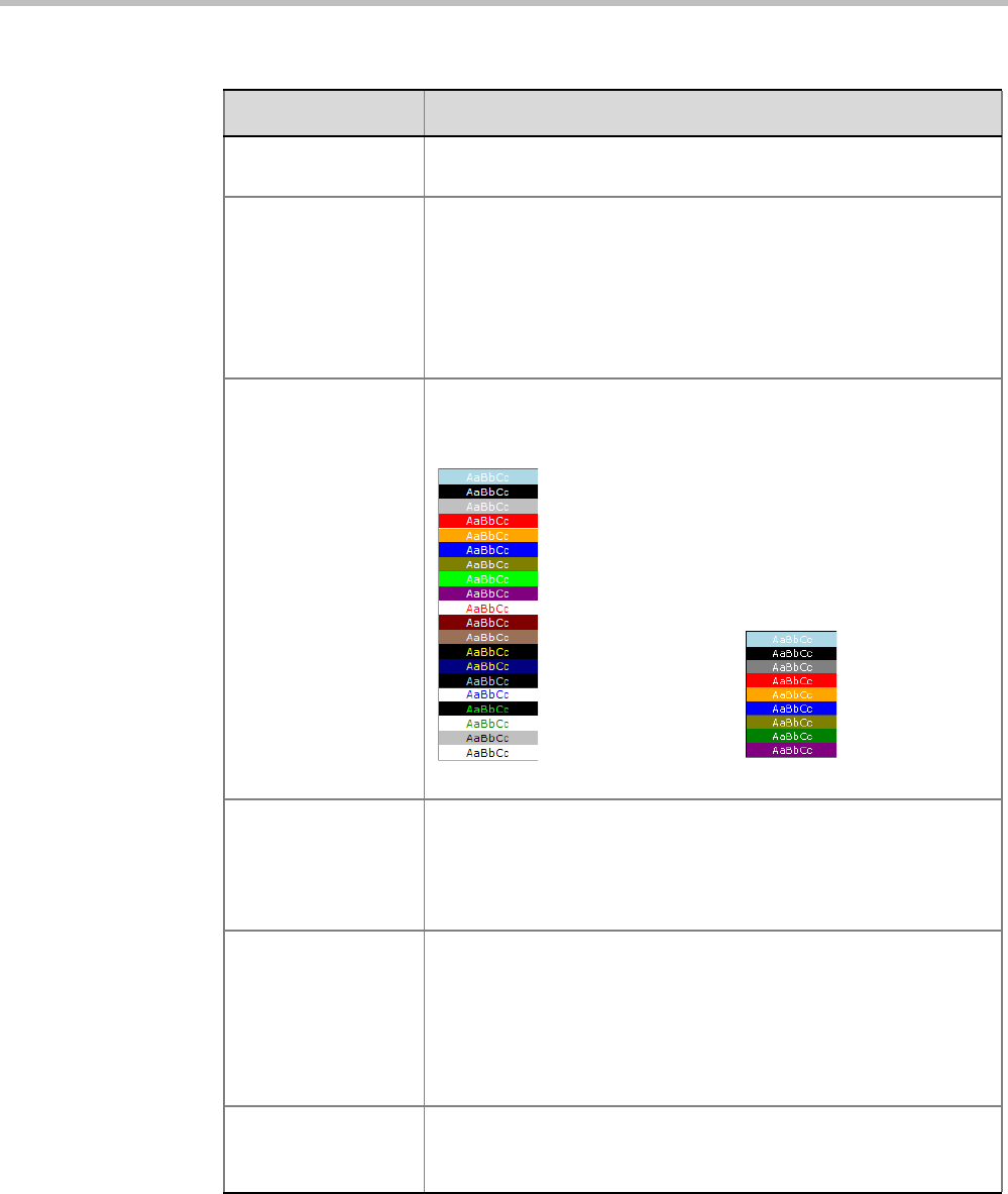
Polycom® RealPresence Collaboration ServerVirtual Edition Administrator’s Guide
2-42 Polycom, Inc.
Content Enter the message text. The message text can be up to 50 Chinese
characters.
Font Size Click the arrows to adjust the font size (points) for the Message
Overlay display.
Range: 9 - 32
Default: 24
Note: In some languages, for example Russian, when a large font
size is selected, both rolling and static messages may be truncated if
the message length exceeds the resolution width.
Color From the drop-down menu select the color and background of the
Message Overlay display text.
The choices are:
Default: White Text on Red Background.
Vertical Position Move the slider to the right to move the vertical position of the
Message Overlay downward within the Video Layout.
Move the slider to the left to move the vertical position of the
Message Overlay upward within the Video Layout.
Default: Top Left (10)
Background
Transparency
Move the slider to the left to decrease the transparency of the
background of the Message Overlay text. 0 = No transparency (solid
background color).
Move the slider to the right to increase the transparency of the
background of the Message Overlay text. 100 = Full transparency (no
background color).
Default: 50
Display Repetition Click the arrows to increase or decrease the number of times that the
text message display is to be repeated.
Default: 3
Table 2-20 New AVC CP Profile - Message Overlay Parameters (Continued)
Field Description
MPMx Mode
Color Options
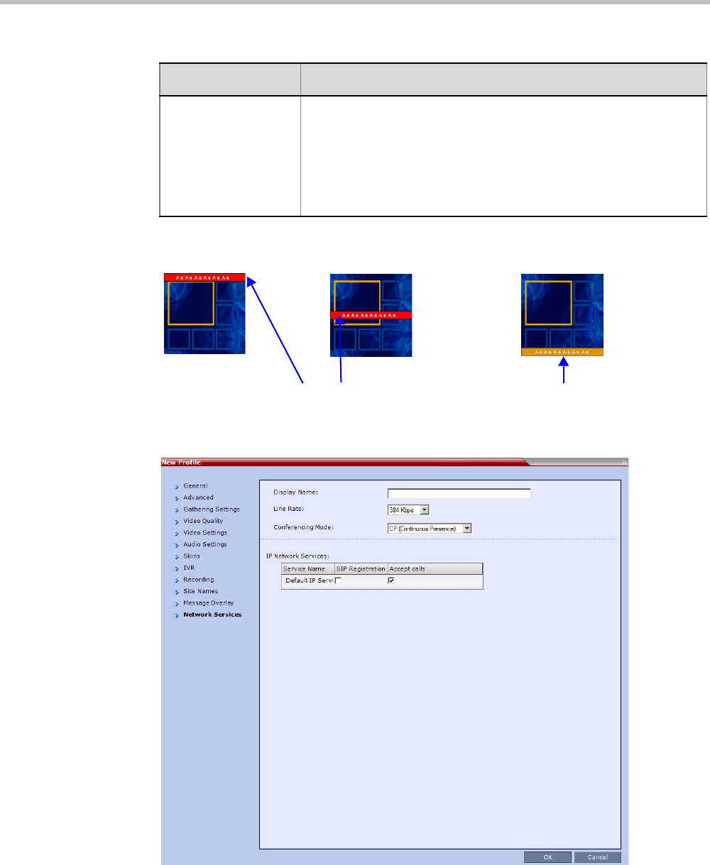
Chapter 2-Conference Profiles
Polycom, Inc. 2-43
As the fields are modified the Preview changes to show the effect of the changes.
For example:
21 Click the Network Services tab.
The New Profile - Network Services tab opens.
Registration of conferencing entities such as ongoing conferences, Meeting Rooms,
Entry Queues and SIP Factories with SIP servers is done per conferencing entity. This
allows better control on the number of entities that register with each SIP server.
Display Speed Select whether the text message display is static or moving across
the screen, the speed in which the text message moves:
•Static
•Slow
•Fast
Default: Slow
Table 2-20 New AVC CP Profile - Message Overlay Parameters (Continued)
Field Description
Small Text, White on red, Top, Middle Small Text, White on yellow, Bottom

Polycom® RealPresence Collaboration ServerVirtual Edition Administrator’s Guide
2-44 Polycom, Inc.
Selective registration is enabled by assigning a conference Profile in which registration
is configured to the required conferencing entities. Assigning a conference Profile in
which registration is not configure to conferencing entities will prevent them from
registering. By default, Registration is disabled in the Conference Profile, and must be
enabled in Profiles assigned to conferencing entities that require registration.
22 Define the following parameters:
23 Click OK to complete the Profile definition.
A new Profile is created and added to the Conference Profiles list.
Table 2-21 New AVC CP Profile - Network Services Parameters
Parameter Description
IP Network Services:
Service Name This column lists all the defined Network Services, one or several
depending on the system configuration.
SIP Registration To register the conferencing entity to which this profile is assigned
with the SIP Server of the selected Network Service, click the check
box of that Network Service in this column.
When SIP registration is not enabled in the conference profile, the
Collaboration Server's registering to SIP Servers will each register
with an URL derived from its own signaling address.
Accept Calls To prevent dial in participants from connecting to a conferencing
entity when connecting via a Network Service, clear the check box of
the Network Service from which calls cannot connect to the
conference.
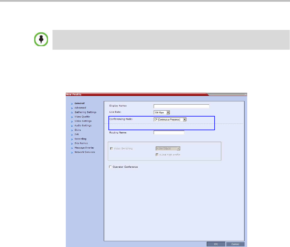
Chapter 2-Conference Profiles
Polycom, Inc. 2-45
Defining SVC Conferencing Profiles
To define SVC Only Profile:
1In the Collaboration Server Management pane, click Conference Profiles.
2In the Conference Profiles pane, click the New Profile button.
The New Profile – General dialog box opens.
By default, the Profile is set to CP Conferencing Mode.
3In the Conferencing Mode list, select SVC Only to define the SVC Profile.
In the RealPresence CloudAxis Solution, the Conference Profiles are defined in the RealPresence
DMA system component and should not be defined directly in the RealPresence Collaboration
Server Virtual Edition component.
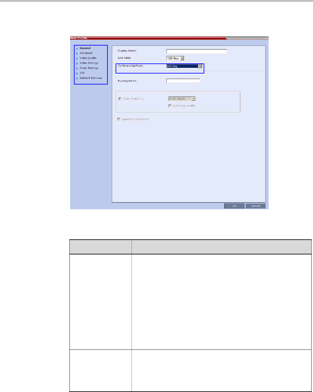
Polycom® RealPresence Collaboration ServerVirtual Edition Administrator’s Guide
2-46 Polycom, Inc.
The profile tabs and options change accordingly and only supported options are
available for selection. Unsupported options are disabled (grayed out).
4Define the Profile name and, if required, the Profile - General parameters:
Table 2-22 New SVC Profile - General Parameters
Field/Option Description
Display Name Enter a unique Profile name, as follows:
•
English text uses ASCII encoding and can contain the most
characters (length varies according to the field).
•European and Latin text length is approximately half the length of
the maximum.
•Asian text length is approximately one third of the length of the
maximum.
It is recommended to use a name that indicates the Profile type, such
as Operator conference or Video Switching conference.
Note: This is the only parameter that must be defined when creating
a new profile.
Note: This field is displayed in all tabs.
Line Rate Select the conference bit rate. The line rate
represents the combined
video, audio and Content rate
.
The default setting for SVC Only conference is 1920kbps.
Notes:
•This field is displayed in all tabs.
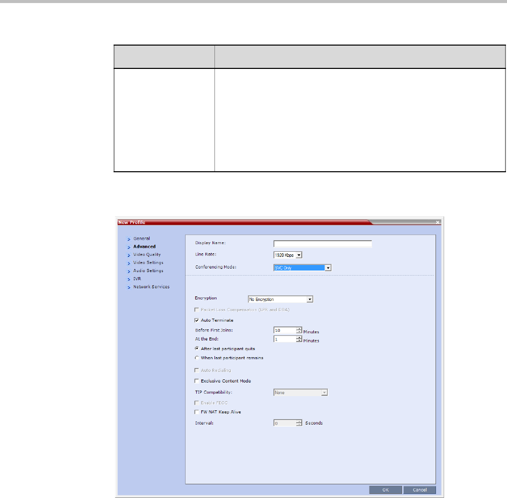
Chapter 2-Conference Profiles
Polycom, Inc. 2-47
5Click the Advanced tab.
The New Profile – Advanced dialog box opens.
Routing Name Enter the Profile name using ASCII characters set.
The Routing Name can be defined by the user or automatically
generated by the system if no Routing Name is entered as follows:
•If an all ASCII text is entered in Display Name, it is used also as
the Routing Name.
•If any combination of Unicode and ASCII text (or full Unicode text)
is entered in Display Name, the ID (such as Conference ID) is
used as the Routing Name.
Table 2-22 New SVC Profile - General Parameters (Continued)
Field/Option Description

Polycom® RealPresence Collaboration ServerVirtual Edition Administrator’s Guide
2-48 Polycom, Inc.
6Define the following supported parameters:
Table 2-23 New SVC Profile - Advanced Parameters
Field/Option Description
Encryption Select the Encryption option for the conference:
•Encrypt All - Encryption is enabled for the conference and all
conference participants must be encrypted.
•No Encryption - Encryption is disabled for the conference.
•Encrypt when Possible - enables the negotiation between the
MCU and the endpoints and let the MCU connect the participants
according to their capabilities, where encryption is the preferred
setting. For connection guidelines see "Mixing Encrypted and
Non-encrypted Endpoints in one Conference” on page 3-27.
For more information, see "Media Encryption” on page 3-26.
Auto Terminate When selected (default), the conference automatically ends when the
termination conditions are met:
Before First Joins — No participant has connected to a conference
during the n minutes after it started. Default idle time is 10 minutes.
At the End - After Last participant Quits — All the participants
have disconnected from the conference and the conference is idle
(empty) for the predefined time period. Default idle time is 1 minute.
At the End - When Last Participant Remains — Only one
participant is still connected to the conference for the predefined time
period (excluding the recording link which is not considered a
participant when this option is selected).
It is not recommended to select this option for SVC Conferences.
Default idle time is 1 minute.
Exclusive Content
Mode
When selected, Content broadcasting is limited to one participant
preventing other participants from interrupting the Content
broadcasting while it is active. For more details, see
FW NAT Keep Alive When selected, an FW NAT Keep Alive message is sent at an interval
defined in the field below the check box.
Interval The time in seconds between FW NAT Keep Alive messages.
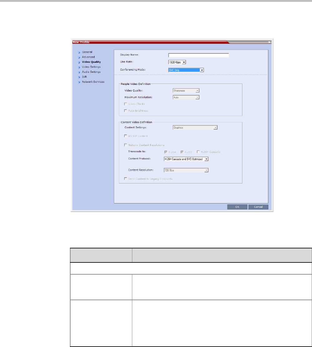
Chapter 2-Conference Profiles
Polycom, Inc. 2-49
7Click the Video Quality tab.
The New Profile – Video Quality dialog box opens.
8In SVC Profiles, the video and Content sharing parameters cannot be modified and they
are set to the following parameters:
Table 2-24 New SVC Profile - Video Quality Parameters
Field/Option Description
Content Video Definition
Content Settings Only Graphics is available in SVC Conferencing Mode for
transmission of Content. It offers the basic mode, intended for normal
graphics. For more information, see "Content Sharing” on page 3-1.
Content Protocol H.264 Cascade and SVC Optimized is the only available Content
Protocol for content sharing during SVC-based conferences.
In this mode, all Content is shared using the H.264 content protocol
and all endpoints must use the set video resolution and frame rate
(720p 5fps). Endpoints that do not support these settings cannot
share content.
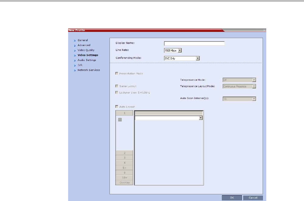
Polycom® RealPresence Collaboration ServerVirtual Edition Administrator’s Guide
2-50 Polycom, Inc.
9Click the Video Settings tab.
By default, the layout is set to Auto Layout and it cannot be changed. All other video
settings options are unavailable in SVC Only conferences.
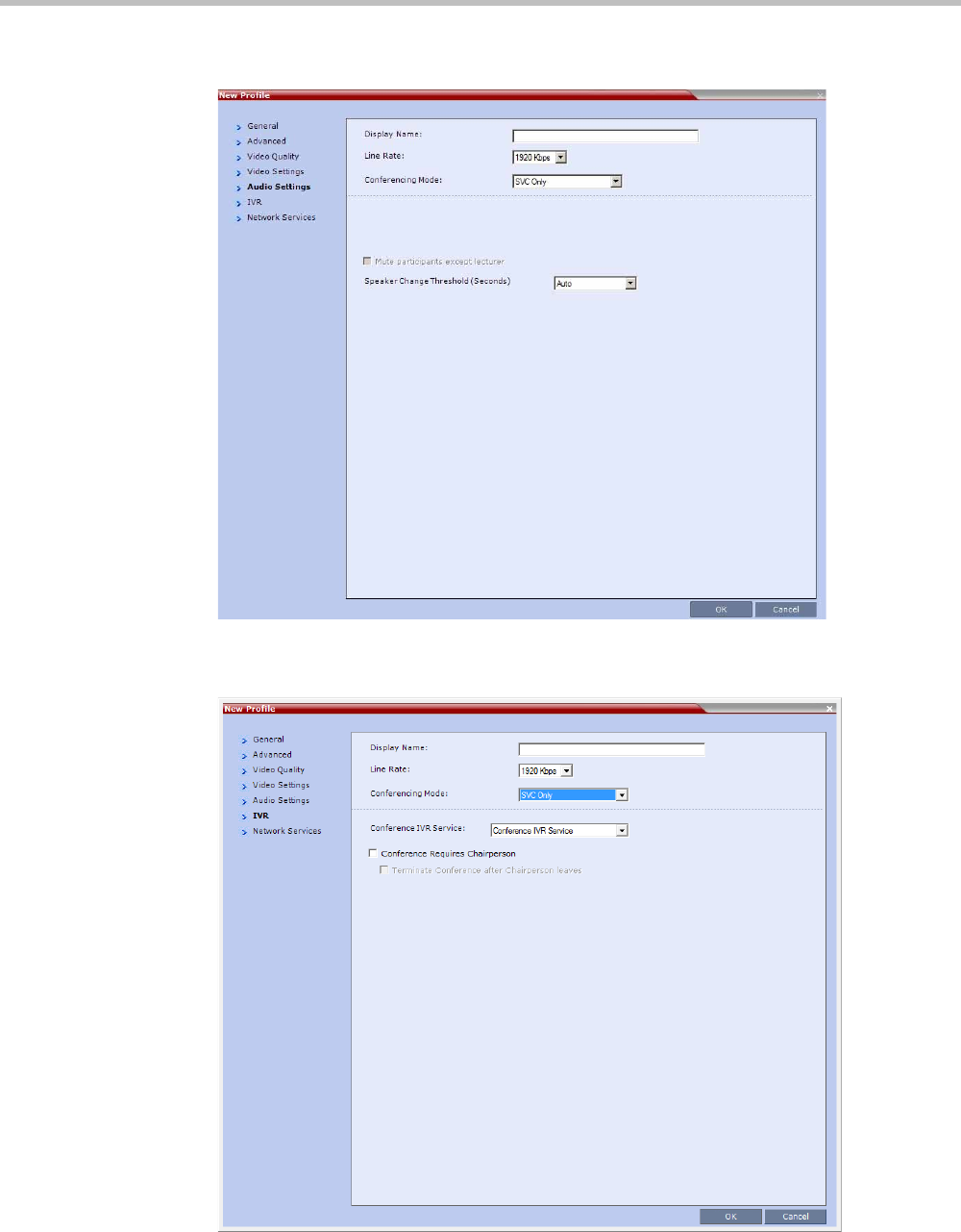
Chapter 2-Conference Profiles
Polycom, Inc. 2-51
10 Click the Audio Settings tab.
All the Audio options are disabled in SVC Only Profiles.
11 Click the IVR tab.

Polycom® RealPresence Collaboration ServerVirtual Edition Administrator’s Guide
2-52 Polycom, Inc.
12 If required, set the following parameters:
The following IVR features are not supported during SVC conferences:
—Invite Participants
—Entry and Exit tones
13 Click the Network Services tab.
Table 2-25 New AVC CP Profile - IVR Parameters
Field/Option Description
Conference IVR
Service
The default conference IVR Service is selected. You can select
another conference IVR Service if required.
Conference Requires
Chairperson
Select this option to allow the conference to start only when the
chairperson connects to the conference and to automatically
terminate the conference when the chairperson exits. Participants
who connect to the conference before the chairperson are placed on
Hold and hear background music (and see the Welcome video slide).
Once the conference is activated, the participants are automatically
connected to the conference.
When the check box is cleared, the conference starts when the first
participant connects to it and ends at the predefined time or according
to the Auto Terminate rules when enabled.
Terminate conference
after chairperson
leaves
Select this check box to automatically terminate the conference after
the chairperson leaves. When the chairperson leaves, the
“Chairperson Has Left” IVR message is played to all participants, at
which point the conference terminates. This way an operator does not
need to monitor a conference to know when to terminate it manually.
If there is a single chairperson in the conference who is changed to a
regular participant the conference will be terminated as if the
chairperson left. If there is more than one chairperson, then changing
one chairperson to a regular participant will not terminate the
conference. It is therefore recommended that before changing a
single chairperson to regular participant, another participant first be
changed to chairperson.
Note: The Chairperson can be either an AVC-enabled or SVC-
enabled endpoint.
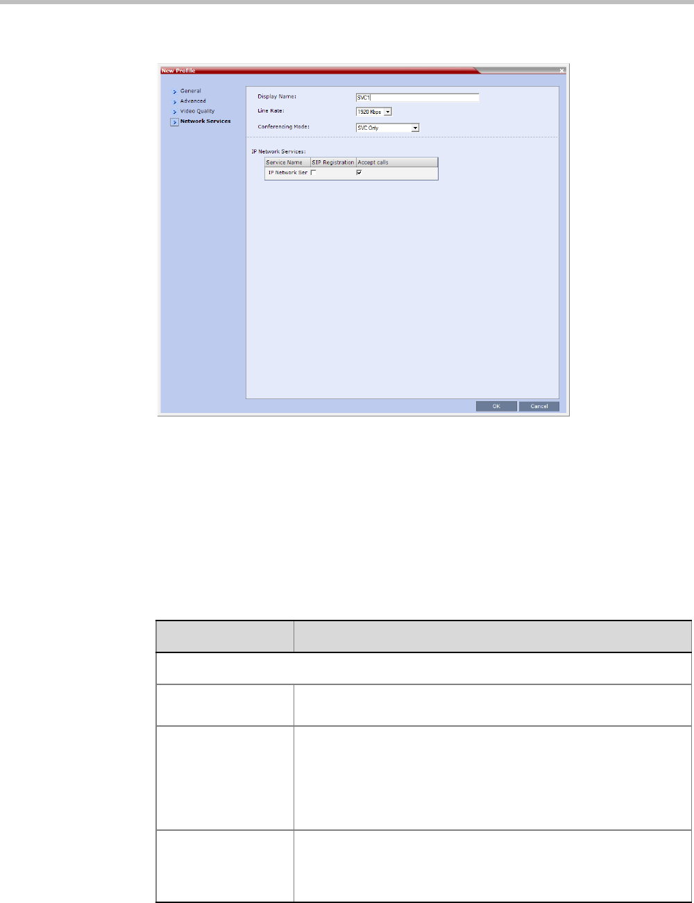
Chapter 2-Conference Profiles
Polycom, Inc. 2-53
The New Profile - Network Services tab opens.
Registration of conferencing entities such as ongoing conferences, Meeting Rooms, and
SIP Factories with SIP servers is done per conferencing entity. This allows better control
of the number of entities that register with each SIP server. Selective registration is
enabled by assigning a conference Profile in which registration is configured for the
required conferencing entities. Assigning a conference Profile in which registration is
not configure for conferencing entities will prevent them from registering. By default,
Registration is disabled in the Conference Profile, and must be enabled in Profiles
assigned to conferencing entities that require registration.
14 Define the following parameters:
Table 2-26 New SVC Profile - Network Services Parameters
Parameter Description
IP Network Services:
Service Name This column lists all the defined Network Services, one or several
depending on the system configuration.
SIP Registration To register the conferencing entity to which this profile is assigned
with the SIP Server of the selected Network Service, click the check
box of that Network Service in this column.
When SIP registration is not enabled in the conference profile, the
Collaboration Server's registering to SIP Servers will each register
with an URL derived from its own signaling address.
Accept Calls To prevent dial in participants from connecting to a conferencing
entity when connecting via a Network Service, clear the check box of
the Network Service from which calls cannot connect to the
conference.
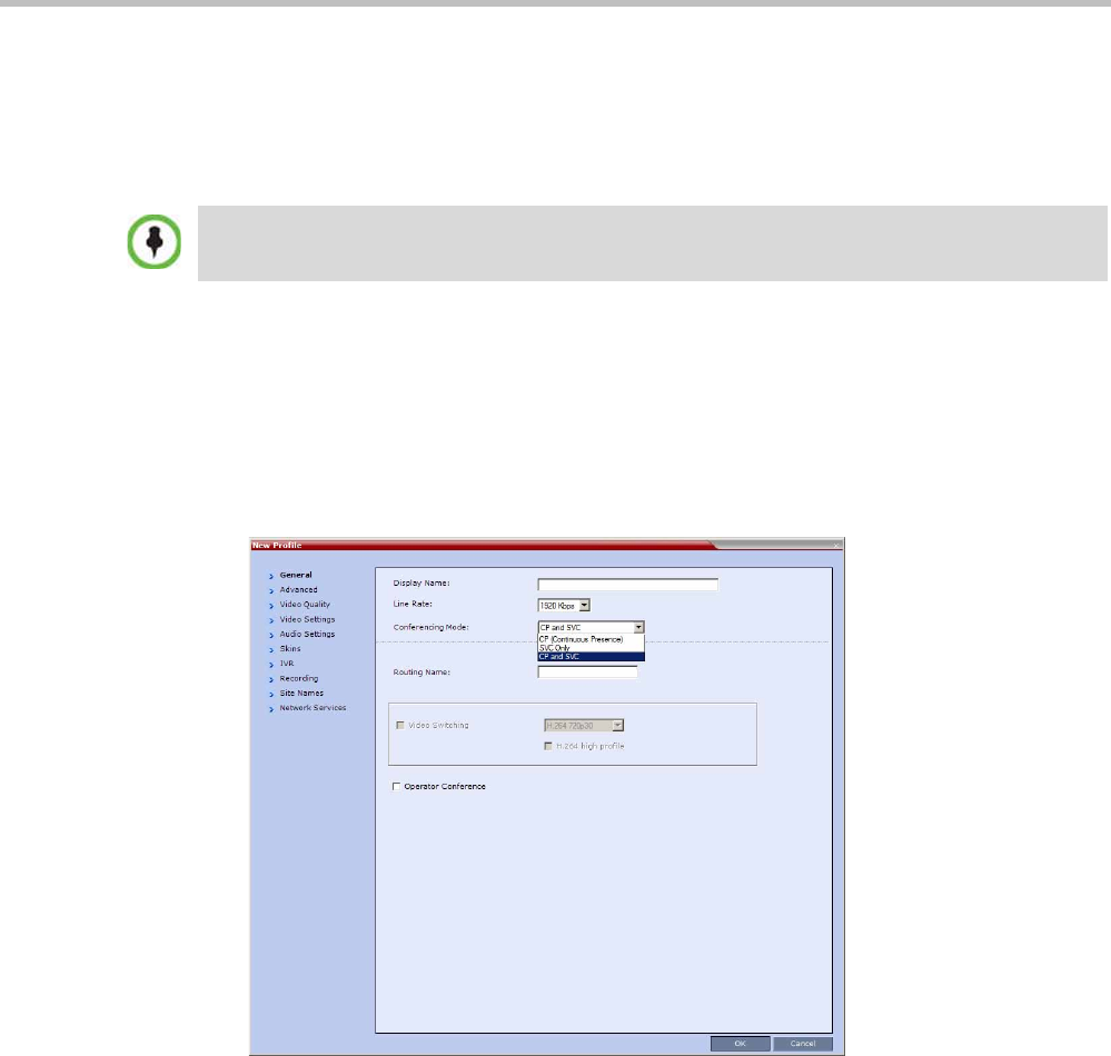
Polycom® RealPresence Collaboration ServerVirtual Edition Administrator’s Guide
2-54 Polycom, Inc.
15 Click OK to complete the Profile definition.
A new Profile is created and added to the Conference Profiles list.
Defining Mixed CP and SVC Conferencing Profiles
The mixed CP and SVC Profile is based on the CP Profile with a few of the CP options
disabled for compatibility between AVC and SVC and to enable the media conversion
between these two modes.
To configure a mixed AVC and SVC conference:
1In the RealPresence Collaboration Server Management pane, click Conference Profiles.
2In the Conference Profiles pane, click the New Profile button.
The New Profile - General dialog box is displayed.
3In the Conferencing Mode list, select CP and SVC to define a mixed AVC and SVC
conference.
For a detailed description of the CP and SVC Profile options refer to "Defining AVC CP
Conferencing Profiles” on page 2-21.
CP Conferencing Additional Information
This section includes detailed explanation of various CP Profile settings.
In the RealPresence CloudAxis Solution, the Conference Profiles are defined in the RealPresence
DMA system component and should not be defined directly in the RealPresence Collaboration
Server Virtual Edition component.
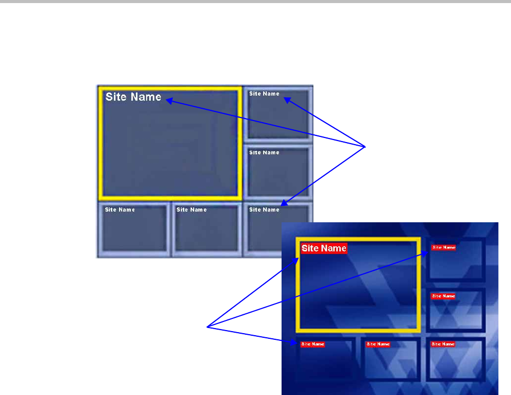
Chapter 2-Conference Profiles
Polycom, Inc. 2-55
Site Names Definition
Using the Site Name dialog box, you can control the display of the site names by defining the
font, size, color, background color and transparency and position within the Video Window.
Guidelines
•Site Names display is Off by default in a new profile.
•Site Names can be enabled to function in one of two modes:
—Auto – Site names are displayed for 10 seconds whenever the conference layout
changes.
—On – Site names are displayed for the duration of the conference.
• During the display of the site names, the video frame rate is slightly reduced
•Site Names display characteristics (position, size, color) can by modified during an
ongoing conference using the Conference Properties - Site Names dialog box. Changes are
immediately visible to all participants.
•Site Names display text and background color is dependent on the Skin selected for the
conference:
—Plain Skins - Site Names text is displayed without a background.
Site Names without Background
(Plain Skin)
Site Names with Background
(Picture Skin)
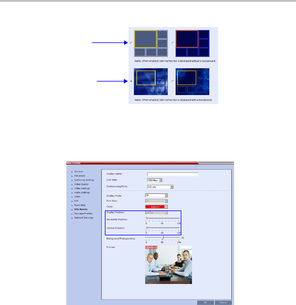
Polycom® RealPresence Collaboration ServerVirtual Edition Administrator’s Guide
2-56 Polycom, Inc.
—Picture Skins - Site Names text is displayed with a background.
Site Names Display Position
The Site Names display position is controlled using three fields in the Site Names tab:
•Display Position drop-down menu
•Horizontal Position slider
•Vertical Position slider
Using these three fields, the position at which the Site Names are displayed in the Video
Windows can be set by:
• Selecting a preset position from the drop-down menu in the Display Position field.
•Moving the Horizontal and Vertical Position sliders.
• Selecting Custom and moving the Horizontal and Vertical Position sliders.
Plain Skins
Picture Skins
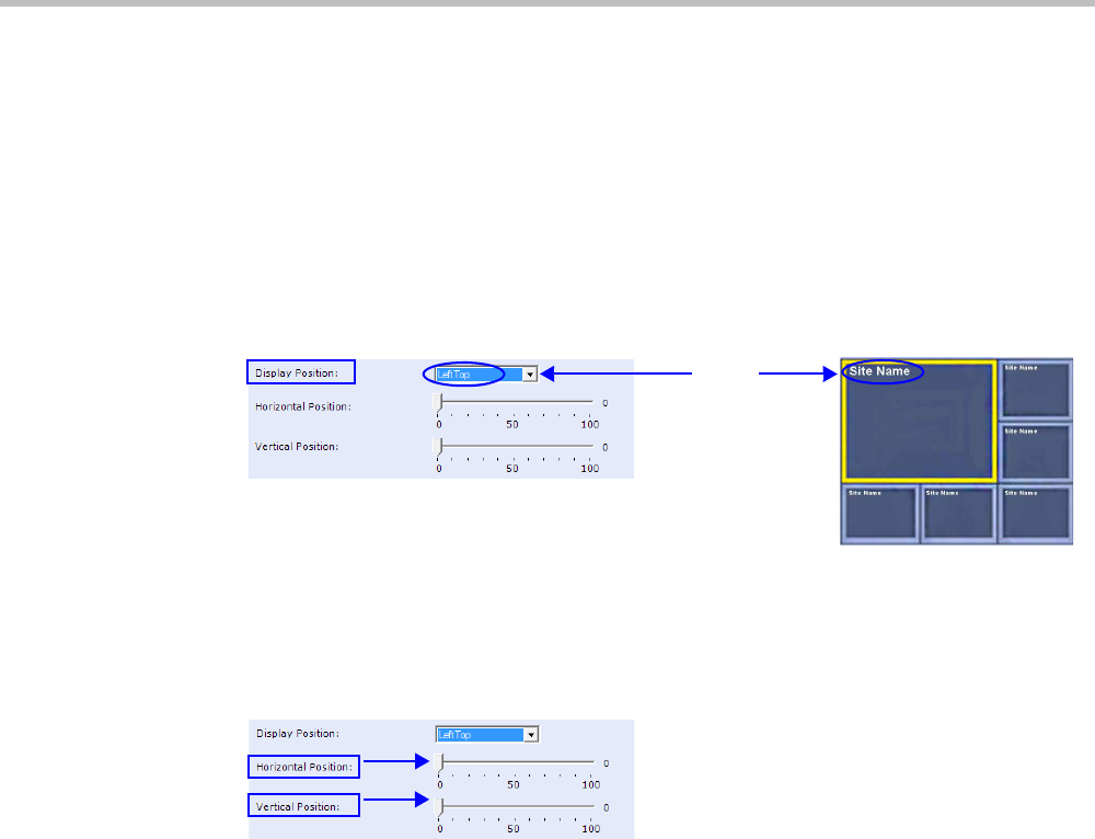
Chapter 2-Conference Profiles
Polycom, Inc. 2-57
Selecting a preset position from the drop-down menu in the Display Position field
>> In the Display Position drop-down menu select a preset position for Site Names display.
Preset positions include:
LeftTop Top RightTop
LeftMiddle RightMiddle
LeftBottom Bottom RightBottom
Custom
When Custom is selected, the current position becomes the initial position for Site Names
position adjustments using the Horizontal and Vertical Position sliders.
The Horizontal and Vertical Position sliders are automatically adjusted to match the
Display Position drop-down menu preset selection.
Moving the Horizontal and Vertical Position sliders
>> Drag the Horizontal and Vertical Position sliders to adjust the position of the Site Names
display.
The Site Names display moves from its current position according to the slider
movement.
Dragging the sliders causes the Display Position drop-down menu field to be set
Custom.
Selecting Custom and moving the Horizontal and Vertical Position sliders
1In the Display Position drop-down menu select Custom.
The current Site Names position becomes the initial position for Site Names position.
Dragging the Horizontal and Vertical Position sliders moves the Site Names from this
position.
2Drag the Horizontal and Vertical Position sliders to adjust the position of the Site Names
display.
Preset
Position
LeftTop

Polycom® RealPresence Collaboration ServerVirtual Edition Administrator’s Guide
2-58 Polycom, Inc.
Message Overlay for Text Messaging
Message Overlay allows the operator or administrator to send text messages to a single,
several or all participants during an ongoing conference.
The text message is seen as part of the in the participant’s video layout on the endpoint
screen or desktop display.
Guidelines
•Message Overlay messaging is supported in:
—Continuous Presence (CP) conferences
—in Same Layout mode
—in encrypted conferences
•Messages Overlay can be enabled or disabled during the ongoing conference.
•Text messages Content can be changed on the fly during the ongoing conference.
•Message Overlay text messages are supported in Unicode or ASCII characters.
• The number of characters for each language can vary due to the type of font used, for
example, the available number of characters for Chinese is 18, while for English and
Russian it is 48.
•In an Event Mode conference with Lecture Mode enabled, only the Lecturer can see the
Message Overlay text, while other participants on the lecturer's level cannot. Participants
on other levels can see the Message Overlay text.
—In some languages, for example Russian, when large font size is selected, both
rolling and static messages may be truncated if the message length exceeds the
resolution width.
• Changes to the Message Overlay display characteristics (position, size, color and speed)
are immediately visible to all participants.
• Changes to the Message Overlay Content are immediately visible to all participants.
When there is a current Message Overlay:
—The current message is stopped immediately.
—The Display Repetition count is reset to 1.
—The new message Content is displayed <Display Repetition> times or until it is
stopped and replaced by another Content change.
•If a Repeating Message is modified before it has completed all its repetitions, it is changed
immediately without completing all of its repetitions. The modified Repeating Message is
displayed starting with repetition one.
•Message Overlay messaging is not supported in Lecture mode.
• If during the ongoing conference the Show Number of Participants DTMF option
(default DTMF *88) is used, when the displayed number of participants is removed, the
message overlay text is also removed.
Overlay
Message Overlay

Chapter 2-Conference Profiles
Polycom, Inc. 2-59
• Participants that have their video suspended do not receive Message Overlays messages.
•Message Overlay text messages cannot be sent via the Content channel.
•Message Overlay messages are not displayed when the PCM menu is active.
•Message Overlay text settings are not saved in the Conference Template when saving an
ongoing conference as a Conference Template.
• Sending text messages using Message Overlay can be enabled or disabled during the
ongoing conference. For more details, see the Polycom® RealPresence Collaboration Server
Virtual Edition Getting Started Guide, "Sending Text Messages to All Participants Using
Message Overlay (AVC-based Conferences)” on page 3-63.
• Text messages can be sent to individual or several participants during the ongoing
conferences. For more details, see the Polycom® RealPresence Collaboration Server Virtual
Edition Getting Started Guide, "Sending Messages to Selected Participants Using Message
Overlay” on page 3-70.
For a detailed description of the Message Overlay parameters, see "New AVC CP Profile -
Message Overlay Parameters” on page 2-41.
Exporting and Importing Conference Profiles
Conference Profiles can be exported from one MCU and imported to multiple MCUs in your
environment, enabling you to copy the Conference Profiles definitions to other systems. This
can save configuration time and ensures that identical settings are used for conferences
running on different MCUs. This is especially important in environments using cascading
conferences that are running on different MCUs.
Guidelines
• Administrators can export and import Conference Profiles. Operators are only allowed to
export Conference Profiles.
• You can select a single, multiple, or all Conference Profiles to be exported.
•Conference Templates and their related Conference Profiles can be exported and imported
simultaneously using the Conference Templates export and import function. For more
information, see the Exporting and Importing Conference Templates section.
Exporting Conference Profiles
Conference Profiles are exported to a single XML file that can be used to import the Conference
Profiles on multiple MCUs.
Using the Export Conference Profile feature, you can:
•Export all Conference Profiles from an MCU
•Export selected Conference Profiles
Exporting All Conference Profiles from an MCU
To export all Conference Profiles from an MCU:
1In the RealPresence Collaboration Server Management pane, expand the Rarely Used list.
2Click the Conference Profiles button.
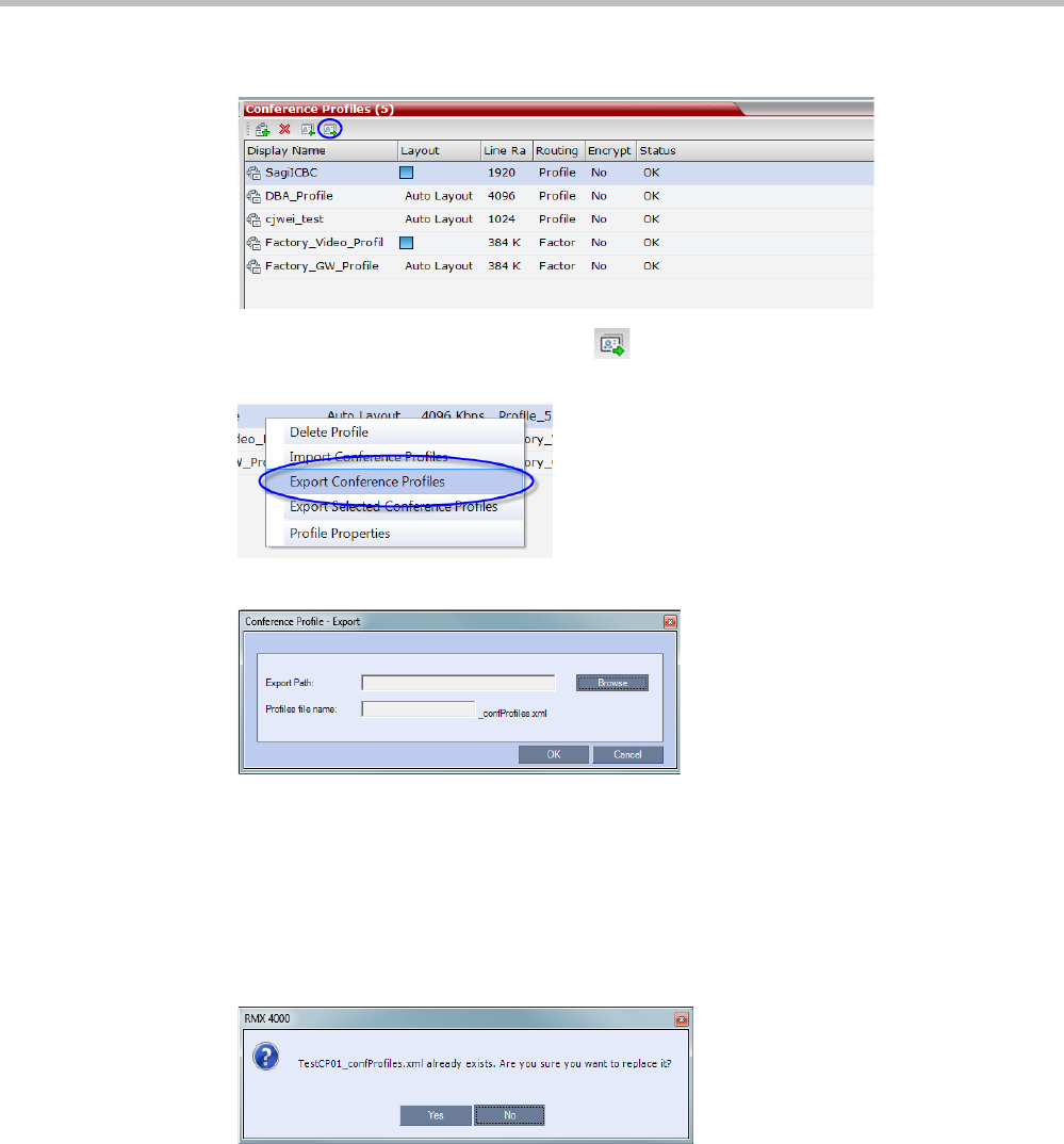
Polycom® RealPresence Collaboration ServerVirtual Edition Administrator’s Guide
2-60 Polycom, Inc.
The Conference Profiles are displayed in the List pane.
3Click the Export Conference Profiles button or right-click the Conference Profiles
pane, and then click Export Conference Profiles.
The Conference Profile - Export dialog box is displayed.
4In the Export Path field, click Browse to navigate to the location of the desired path
where you want to save the exported file.
5In the Profiles file name field, type the file name prefix. The file name suffix
(_confProfiles.xml) is predefined by the system. For example, if you type Profiles01, the
exported file name is defined as Profiles01_confProfiles.xml.
6Click OK to export the Conference Profiles to a file.
If the export file with the same file name already exists, a prompt is displayed.
7Click Yes to replace the exported file or click No to cancel the export operation and
return to the Conference Profiles list. You can modify the export file name and restart the
export operation.
Exporting Selected Conference Profiles
You can select a single Conference Profile or multiple Conference Profiles and export them
to a file to be imported to other MCUs in your environment.
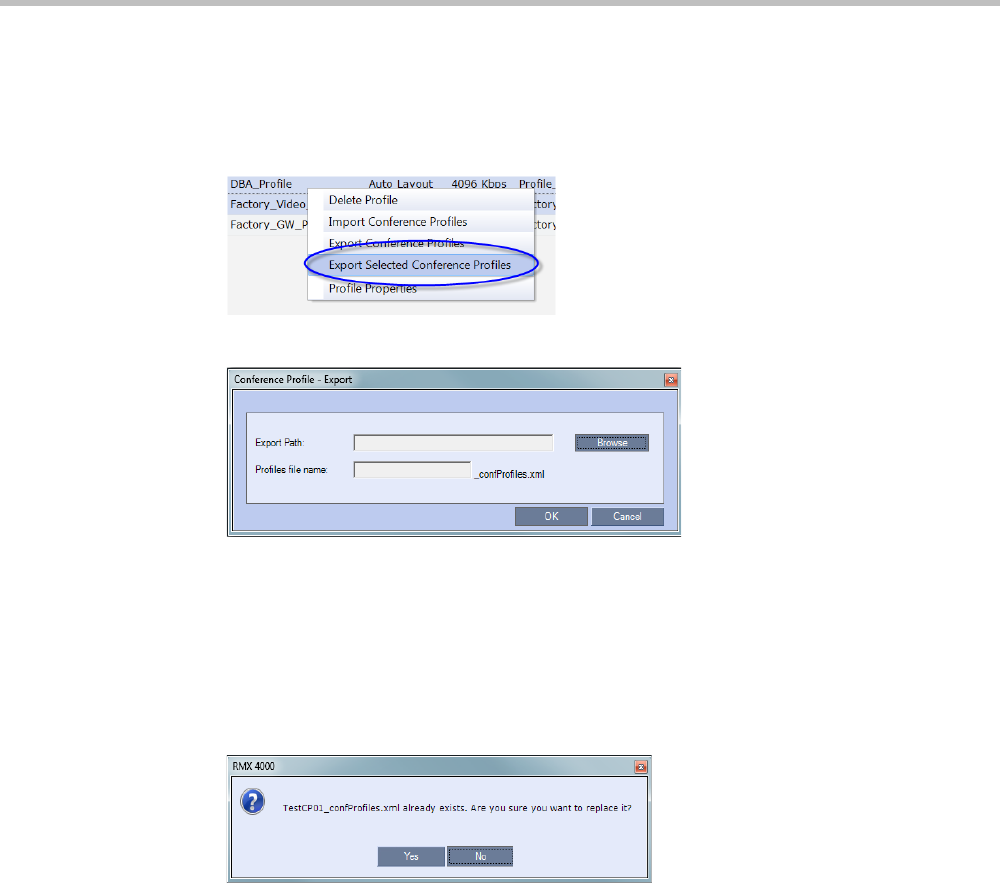
Chapter 2-Conference Profiles
Polycom, Inc. 2-61
To export selected Conference Profiles:
1In the Conference Profiles pane, select the profiles you want to export.
2Right-click the selected Conference Profiles, and then click Export Selected Conference
Profiles.
The Conference Profile - Export dialog box is displayed.
3In the Export Path field, click Browse to navigate to the location of the desired path
where you want to save the exported file.
4In the Profiles file name field, type the file name prefix. The file name suffix
(_confProfiles.xml) is predefined by the system. For example, if you type Profiles01, the
exported file name is defined as Profiles01_confProfiles.xml.
5Click OK to export the Conference Profiles to a file.
If the export file with the same file name already exists, a prompt is displayed.
6Click Yes to replace the exported file or click No to cancel the export operation and
return to the Conference Profiles list. You can modify the export file name and restart the
export operation.
Importing Conference Profiles
You can import Conference Profiles from another MCU in your environment.
To import Conference Profiles:
1In the RealPresence Collaboration Server Management pane, expand the Rarely Used list.
2Click the Conference Profiles button.
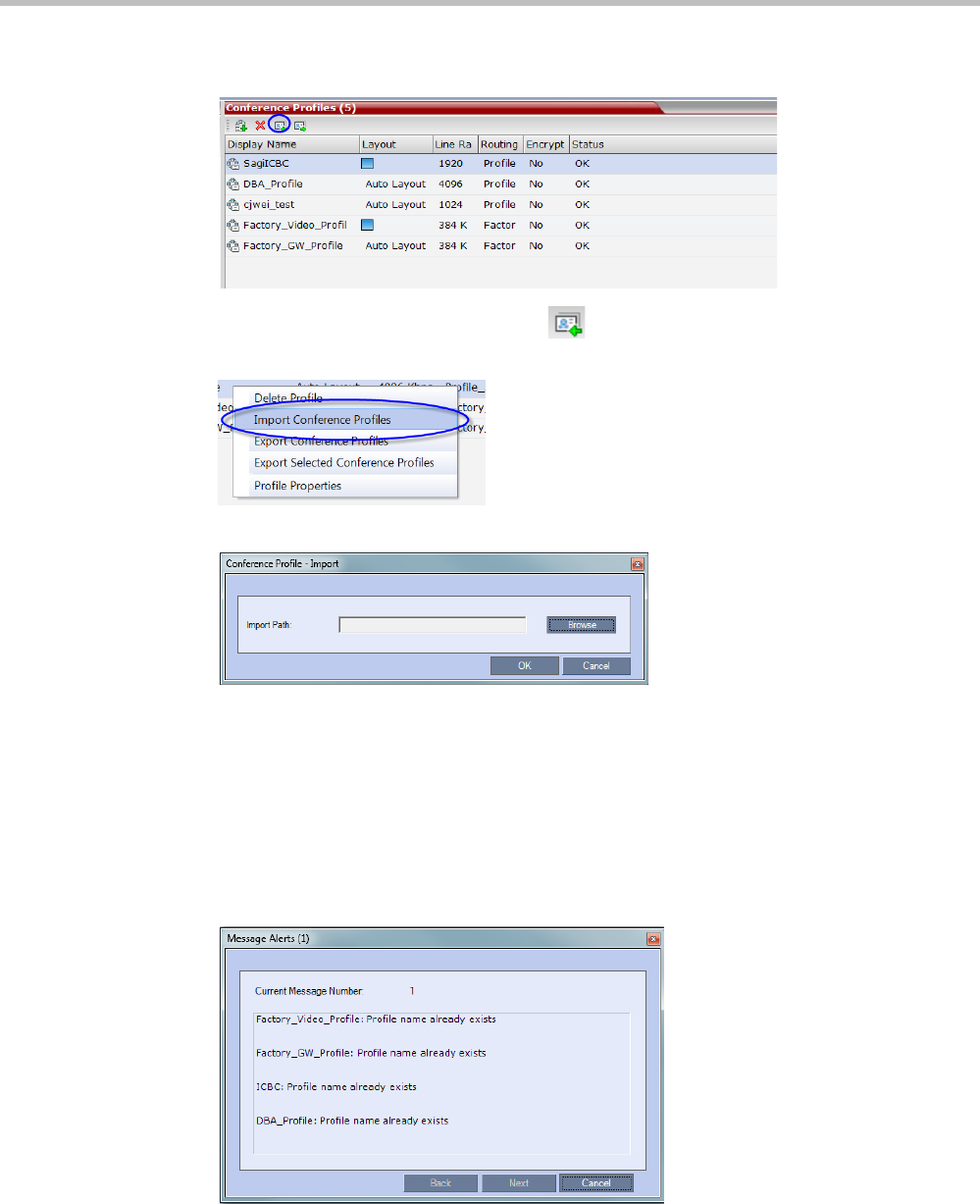
Polycom® RealPresence Collaboration ServerVirtual Edition Administrator’s Guide
2-62 Polycom, Inc.
The Conference Profiles are displayed in the List pane.
3Click the Import Conference Profiles button or right-click the Conference Profiles
pane, and then click Import Conference Profiles.
The Conference Profile - Import dialog box is displayed.
4In the Import Path field, click Browse to navigate to the path and file name of the
exported Conference Profiles you want to import.
5Click OK to import the Conference Profiles.
Conference Profiles are not imported when:
—A Conference Profile already exists
—An IVR Service does not exist for the related Conference Profile
When Conference Profiles are not imported into the Conference Profiles list, a Message
Alert window is displayed with the profiles that were not imported.
Conference Profiles that are not problematic are imported.

Chapter 2-Conference Profiles
Polycom, Inc. 2-63
6Click Cancel to exit the Message Alerts window.
The imported Conference Profiles appear in the Conference Profiles list.

Polycom® RealPresence Collaboration ServerVirtual Edition Administrator’s Guide
2-64 Polycom, Inc.

Polycom, Inc. 3-1
3
Additional Conferencing Information
Various conferencing modes and video features require additional settings, such as system
flag settings, conference parameters and other settings. In depth explanations of these
additional settings are described in the following sections:
•"Content Sharing” on page 3-1
•"Video Preview (AVC Only Participants)” on page 3-20
•"Media Encryption” on page 3-26
•"Packet Loss Compensation (LPR and DBA) AVC CP Conferences” on page 3-34
•"Lecture Mode (AVC CP Only)” on page 3-38
•"Lecture Mode (AVC CP Only)” on page 3-38
•"Audio Algorithm Support” on page 3-45
•"Permanent Conference” on page 3-49
Content Sharing
Content such as graphics, presentations, documents or live video can be shared with
conference participants using the H.239 (H.323) or BFCP (SIP) protocol, which is the
standard protocols for content sharing.
H.239 Protocol
The H.239 protocol allows compliant endpoints to transmit and receive two simultaneous
video streams:
•People video stream – video is displayed in Continuous Presence conferences or in
Media Relay (SVC) conferencing Mode
•Content video stream – Video Switching mode for content sharing
By default, all conferences, Entry Queues, and Meeting Rooms launched on the Collaboration
Server have H.239 capabilities.
To view Content, endpoints must use the same Bit Rate, Protocol, and Resolution. Endpoints
may not send Content while connecting to an Entry Queue.
Endpoints without H.239 capability can connect to the video conference without Content.
Cascade links declare H.239 capabilities and they are supported in Star cascading
topologies. For more details, see "Basic Cascading” on page 5-3.
In the RealPresence CloudAxis Solution, the conferencing parameters are defined in the
RealPresence DMA system component and should not be defined directly in the RealPresence
Collaboration Server Virtual Edition component.

Polycom® RealPresence Collaboration ServerVirtual Edition Administrator’s Guide
3-2 Polycom, Inc.
SIP BFCP Content Capabilities
SIP Clients supporting BFCP over UDP, when connected to conferences on the
Collaboration Server, can share Content with endpoints supporting the following Content
sharing protocols:
•BFCP/TCP
•BFCP/UDP
•H.323/ H.239
•H.323 /Polycom People+Content
Guidelines
For SIP Clients that support both BFCP/TCP and BFCP/UDP:
• The preferred protocol is BFCP/UDP.
• When used in Cascading conferences, the Cascade Link must be H.323.
•BFCP/UDP is supported in both IPv4 and IPv6 addressing modes.
•BFCP utilizes an unsecured channel (port 60002/TCP) even when SIP TLS is enabled. If
security is of higher priority than SIP content sharing, SIP People+Content can be
disabled. To do this manually add the ENABLE_SIP_PEOPLE_ PLUS_CONTENT
System Flag to the System Configuration and set its value to NO.
•SIP People+Content and BFCP capabilities are by default declared to all endpoints. If,
however, the endpoint identity is hidden by a proxy server, these capabilities will not
be declared by the Collaboration Server. Capabilities declaration is controlled by the
ENABLE_SIP_PPC_FOR_ALL_USER_AGENT System Flag.
The default value of the ENABLE_SIP_PPC_FOR_ALL_USER_AGENT System Flag is
YES resulting in BFCP capability being declared with all vendors’ endpoints unless it is
set to NO. When set to NO, the Collaboration Server will declare SIP People+Content
and BFCP capabilities to Polycom and Avaya endpoints.
•The ENABLE_FLOW_CONTROL_REINVITE System Flag should be set to NO when
SIP BFCP is enabled.
• If these System Flags don’t exist in the system, they must be manually added. For more
information see "Modifying System Flags” on page 20-1.
• BFCP capabilities are not supported in Microsoft ICE environment.
Dial-out Connections:
•For dial-out connections to SIP Clients, BFCP/UDP protocol can be given priority by
adding the adding the SIP_BFCP_DIAL_OUT_MODE System Flag to system.cfg and
setting its value to UDP.

Chapter 3-Additional Conferencing Information
Polycom, Inc. 3-3
The Collaboration Server’ s Content sharing determined by the System Flag’s settings and
SIP Client capabilities are summarized in Table 3-1.
For more information see "Manually Adding and Deleting System Flags” on page 20-12.
Dial-in Connections:
• The Collaboration Server will share content with Dial-in SIP Clients according to their
preferred BFCP protocol.
•SIP Clients connected as Audio Only cannot share Content.
Defining Content Sharing Parameters for a Conference
Content can be shared using two main methods:
• Content Highest common parameters (also known as Content Video Switching)
• Multiple Content Resolutions (not supported with RealPresence Collaboration Server
Virtual Edition)
In Content Video Switching mode, the content is negotiated to highest common capabilities
supported by the endpoints connected to the conference. If the conference includes
participants that support lower content capabilities (such as H.263) and higher content
capabilities (H.264), content will be sent at the lower capabilities supported by all endpoints,
resulting in lower content quality seen by all endpoints.
In this mode, the content is set according to the capabilities of all the participants currently
connected to the conference. If the all the connected participant support the H.264 protocol,
the Content will be started with H.264 capabilities. If then an endpoint supporting only
H.263 protocol connects, the content is stopped in order to switch to H.263 and has to be
resent. If the H.263 participant leaves the conference and only H.264 capable endpoints
remain connected, content is stopped in order to switch back to H.264 and has to be resent.
Table 3-1 System Flag - SIP_BFCP_DIAL_OUT_MODE
Flag Value
SIP Client: BFCP Support
UDP TCP UDP and TCP
AUTO
(Default) BFCP/UDP selected as
Content sharing
protocol.
BFCP/TCP selected as
Content sharing
protocol. BFCP/UDP selected as
Content sharing
protocol.
UDP Cannot share Content.
TCP Cannot share Content.BFCP/TCP selected as
Content sharing protocol.
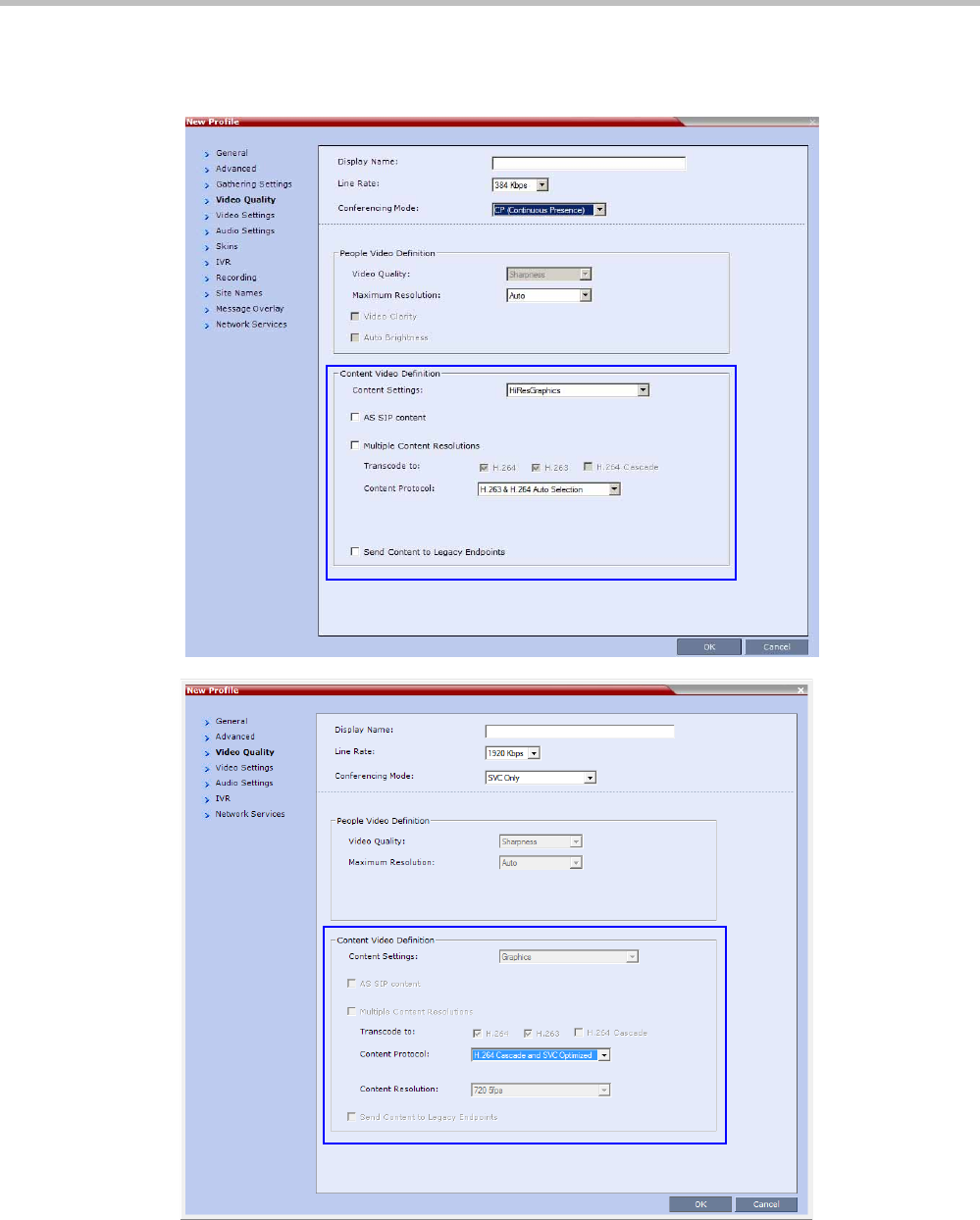
Polycom® RealPresence Collaboration ServerVirtual Edition Administrator’s Guide
3-4 Polycom, Inc.
Content parameters are defined in the Conference Profiles - Video Quality dialog box.
The parameters change according to the Conferencing Mode.
AVC CP
Conferencing
Mode
SVC
Conferencing
Mode
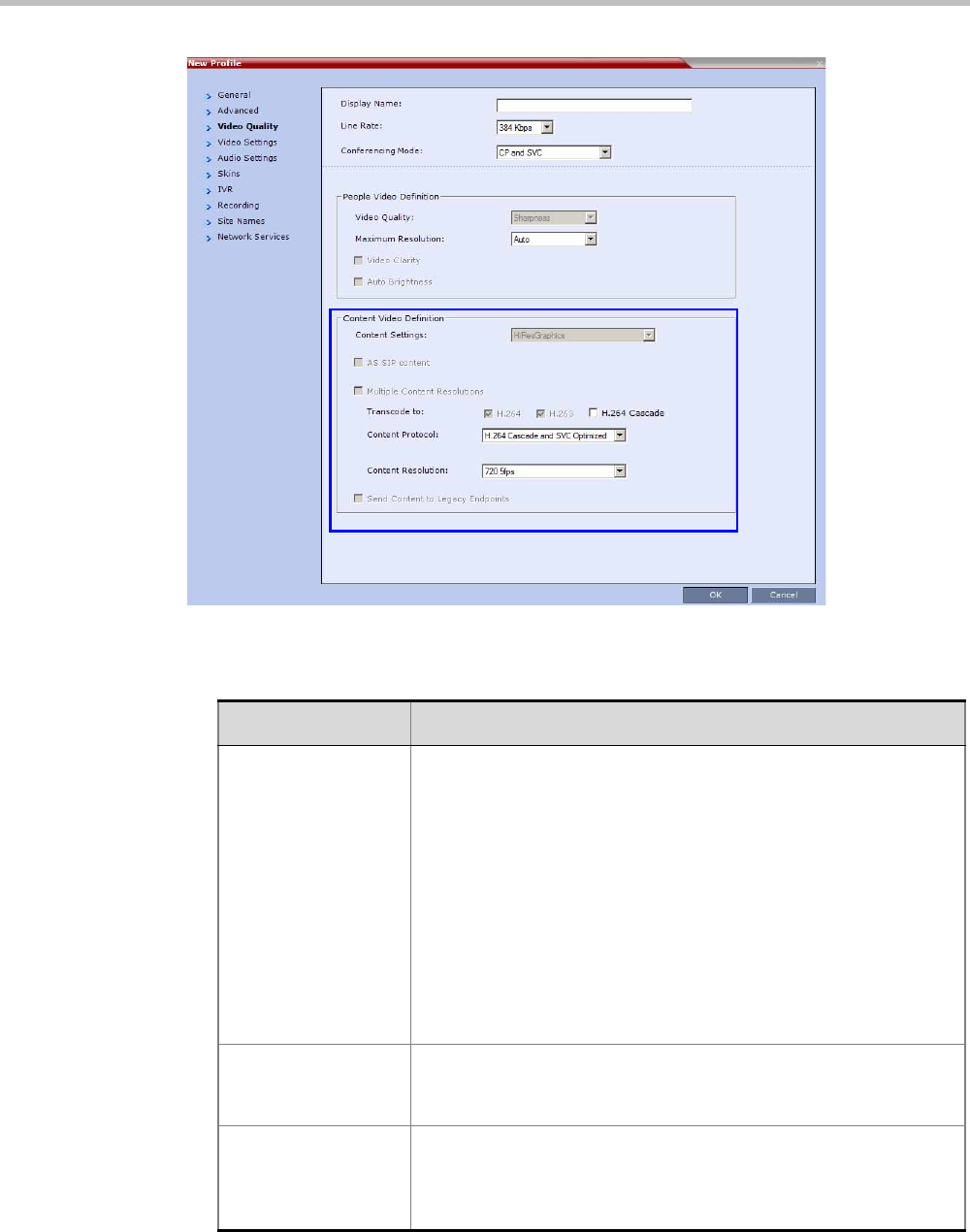
Chapter 3-Additional Conferencing Information
Polycom, Inc. 3-5
1In the Content Video Definition section, select the Content Settings and Protocol as follows:
Mixed CP and
SVC
Conferencing
Mode
Table 3-2 H.239 Content Options
Field Description
Content Settings Select the transmission mode for the Content channel:
•Graphics — basic mode, intended for normal graphics
•Hi-res Graphics (AVC CP Only) — a higher bit rate intended for
high resolution graphic display
•Live Video (AVC CP Only) — Content channel displays live video
•Customized Content Rate (AVC CP Only) - manual definition of
the Conference Content Rate, mainly for cascading conferences.
Selection of a higher bit rate for the Content results in a lower bit rate
for the people channel.
For a detailed description of each of these options, see "Content
Sharing Parameters in Content Highest Common (Content Video
Switching) Mode” on page 3-6.
AS-SIP Content This Content Sharing option is not supported with RealPresence
Collaboration Server Virtual Edition.
Multiple Resolutions This Content Sharing option is not supported with RealPresence
Collaboration Server Virtual Edition.

Polycom® RealPresence Collaboration ServerVirtual Edition Administrator’s Guide
3-6 Polycom, Inc.
2Click OK.
Content Sharing Parameters in Content Highest Common (Content Video
Switching) Mode
This section describes the possible content sharing parameters when content Highest
Common mode is used:
• Content Settings
• Content Protocol
• Content Resolution
Content Protocol •H.263 (AVC CP Only)
•Content is shared using the H.263 protocol.
•Use this option when most of the endpoints support H.263 and
some endpoints support H.264.
•H.263 & H.264 Auto Selection (AVC CP Only)
•Content is shared using H.263 if a mix of H.263-supporting
and H.264-supporting endpoints are connected.
•Content is shared using H.264 if all connected endpoints have
H.264 capability.
•H.264 HD (AVC CP Only, default)
•Ensures high quality Content when most endpoints support
H.264 and HD Resolutions.
•H.264 Cascade and SVC Optimized
•All Content is shared using the H.264 content protocol and is
optimized for use in SVC only and Cascaded Conferences.
For a detailed description of each of these settings, see "Content
Protocols” on page 3-8.
Content Resolution Select a Content Resolution from the drop-down menu.
The Content Resolutions that are available for selection are
dependent on the content sharing mode (Highest Common Content
or Multiple Content Resolutions), Line Rate and Content Settings that
have been selected for the conference.
For a full list of Content Resolutions see "Defining Content Sharing
Parameters for a Conference” on page 3-3.
Note: This field is displayed only when H.264 Cascade is selected
for Multiple Content Resolution or when H.264 Cascade and SVC
Optimized option is selected as the Content Protocol (in the Highest
Common Content Mode) and is enabled for selection in CP
conferences (AVC CP Only). This option is disabled in SVC
conferences.
Send Content to
Legacy Endpoints
This Content Sharing option is not supported with RealPresence
Collaboration Server Virtual Edition.
Table 3-2 H.239 Content Options (Continued)
Field Description

Chapter 3-Additional Conferencing Information
Polycom, Inc. 3-7
Content Settings
The Content channel can transmit one of the following modes:
•Graphics – for standard graphics. This is the default mode in AVC conferences and the
only supported mode for SVC conferences.
•Hi-res Graphics (AVC CP Only) – requiring a higher bit rate, for high quality display or
highly detailed graphics.
•Live Video (AVC CP Only) – highest bit rate, for video clips or live video display.
•Customized Content Rate (AVC CP Only) - that allows manual definition of the
Conference Content Rate.
AVC CP Content Setting
For Graphics, Hi-res Graphics and Live Video, the highest common Content bit rate is
calculated for the conference each time an endpoint connects. Therefore, if an endpoint
connects to an ongoing conference at a lower bit rate than the current bit rate, the Content
bit rate for the current conference is re-calculated and decreased.
Bit rate allocation by the MCU is dynamic during the conference and when the Content
channel closes, the video bit rate of the People conference is restored to its maximum.
During a conference the MCU will not permit an endpoint to increase its bit rate, it can
however change its Content resolution. The Collaboration Server can decrease the allocated
Content bit rate during a conference.
The following table summarizes the bit rate allocated to the Content channel from the video
channel in each of the Content Settings according to the conference line rate:
Table 3-4 summarizes the Maximum Resolution of Content and Frames per Second (fps) for Bit
Rate Allocations to the Content Channel.
Table 3-3 Decision Matrix - Bit Rate Allocation to Content Channel per Conference Line Rate
Content
Settings
Content Bit Rate Allocation per Conference Line Rate (kbps)
64
96 128 256 384 512 768
832
1024
1152
1472
1728 1920
Graphics 64 64 128 128 256 256 256 256
Hi Resolution
Graphics 64 128 192 256 384 384 512 768
Live Video 64 128 256 384 512 768 768 1152
Customized
Content Rate
The Content Bit Rate is selected from a menu in the Content Video
Definition pane. See "Selecting a Customized Content Rate in AVC CP
Conferences” on page 3-13.
Polycom® RealPresence Collaboration ServerVirtual Edition Administrator’s Guide
3-8 Polycom, Inc.
SVC Only and Mixed CP and SVC Content Setting
The Content channel is transmitted in Graphics mode only.
Content Protocols
Two Content Protocols can be used for sharing content:
• H.263 (CP and mixed CP and SVC)
• H.264 (all conferencing modes)
H.264 offers higher quality content, but is not supported by legacy endpoints. Depending on
the endpoints capabilities, you can determine the content sharing experience by selecting
the appropriate protocol and system behavior from the Content Protocol list:
•H.263 & H.264 Auto Selection (AVC CP Only)
•H.263 (AVC CP Only)
•H.264 HD (AVC CP Only)
•H.264 Cascade and SVC Optimized (all conferences)
H.263 & H.264 Auto Selection (AVC CP Conferences)
The H.263 & H.264 Auto Selection option should be selected when Content is to be shared
using a mix of H.263-supporting and H.264-supporting endpoints.
Bit rate allocation to the Content channel by the Collaboration Server is dynamic according
to the conference line rate and Content Setting selected for the conference.
If an endpoint that supports only H.263 for Content Sharing connects to a conference with
Content Protocol set to H.263 & H.264 Auto Selection:
•Content is shared using H.263 even if H.264-supporting endpoints are connected.
•Content is shared using H.264 if all connected endpoints have H.264 capability.
• If the first endpoint to connect to the conference only supports H.263, the H.263 protocol
is used for Content for all conference participants.
•If Content is already being shared using the H.264 protocol when a H.263 endpoint
connects, Content sharing is stopped and must be manually restarted using H.263 (i.e.
the endpoint using H.263 Content Protocol must connect first), for all participants to
receive content. If the H.263 endpoint disconnects, Content sharing must be manually
stopped and restarted and will automatically upgrade to the H.264 protocol.
• Endpoints that do not have at least H.263 capability can connect to the conference but
cannot share Content.
• This option is not available in SVC Conferencing Mode and CP and SVC Conferencing
Mode.
Table 3-4 Content - Maximum Resolution, Frames/Second per Bit Rate Allocation
Bit Rate Allocated to Content
Channel (Kbps)
Content
Maximum Resolution Frames/Second
From 64 and less than 512 H.264 HD720p 5
From 512 and up to 1536 H.264 HD720p 30

Chapter 3-Additional Conferencing Information
Polycom, Inc. 3-9
H.263 (AVC CP Conferences)
Select this option when most of the endpoints support H.263 and some endpoints support
H.264. In such a case, all endpoints will share content using the H.263 protocol, and this
protocol will not change throughout the conference (fixed mode).
Bit rate allocation to the Content channel by the Collaboration Server is dynamic according
to the conference line rate and Content Settings selected for the conference. For more
information see "Content Sharing Parameters in Content Highest Common (Content Video
Switching) Mode” on page 3-6.
This option is not available in SVC Conferencing Mode and CP and SVC Conferencing Mode.
H.264 HD (AVC CP Conferences default)
The H.264 HD option should be selected only if most endpoints in the conference support
H.264 to ensure high quality Content.
When this protocol option is selected, endpoints must connect at Content bit rates above a
minimum as specified by specific System Flags to ensure high quality Content for all
participants. For more information about System Flags see "Setting the Minimum Content Rate
for Each Content Quality Setting for H.264 HD” on page 3-9.
Bit rate allocation to the Content channel by the Collaboration Server is dynamic according
to the conference line rate and Content Setting selected for the conference. For more
information see "Content Sharing Parameters in Content Highest Common (Content Video
Switching) Mode” on page 3-6.
Endpoints that do not support H.264, or those that do not meet the minimum line rate
threshold for the Content Setting will not receive content.
Guidelines
• Only endpoints that support H.264 capability at a resolutions of HD720p5 or higher will
be able to receive and send Content.
• This option is not available in SVC Conferencing Mode and CP and SVC Conferencing
Mode.
• Maximum supported content resolution is HD 720p.
• The minimum Content Rate required for allowing a participant to share Content is the
lower valued parameter when comparing the System Flag setting (Table 3-5) and the
content bit rate allocation derived from the conference line rate (Table 3-6).
When the flag settings enable an endpoint to share Content at a content rate that is
lower than the conference content rate (Table 3-6), the content rate of the entire
conference is reduced to the content rate supported by that endpoint.
Setting the Minimum Content Rate for Each Content Quality Setting for H.264 HD
The following System Flags determine the minimum content rate required for endpoints to
share H.264 high quality content via the Content channel.
A System Flag determines the minimum line rate for each Content Setting:
•Graphics
•Hi Resolution Graphics
•Live Video

Polycom® RealPresence Collaboration ServerVirtual Edition Administrator’s Guide
3-10 Polycom, Inc.
In order to change the System Flag values, the flags must be manually added to the System
Configuration. For more information see "Modifying System Flags” on page 20-1.
Example
Table 3-6 summarizes an example of two participants trying to connect to a conference
running at a Line Rate of 1024Kbps. The Content Setting for the conference is Hi Resolution
Graphics and the H264_HD_HIGHRES_MIN_CONTENT_RATE System Flag setting are
used to determine if Content will be shared with the participant.
Table 3-5 H.264 HD System Flags
Content Settings Flag Name Range Default
Graphics H264_HD_GRAPHICS_MIN_CONTENT_RATE 0-1536 128
Hi Resolution
Graphics
H264_HD_HIGHRES_MIN_CONTENT_RATE 0-1536 256
Live Video H264_HD_LIVEVIDEO_MIN_CONTENT_RATE 0-1536 384
Table 3-6 Participant Content Sharing Based on Connection Line Rate and System Flag Setting
Participant Conference
Flag
Value Result
Line Rate Bit Rate
Allocation
to
Content
Channel
(Table 3-5)
Line Rate Bit Rate
Allocation
to
Content
Channel
(Table 3-5)
Participant 1
384 192
1024 384
128
Participant and
entire conference
share content at
192Kbps
512 Participant will
not receive
content
Participant 2
1024 384
128
Participant and
entire conference
share content at
384Kbps
512
Participant and
entire conference
share content at
384Kbps

Chapter 3-Additional Conferencing Information
Polycom, Inc. 3-11
H.264 Cascade and SVC Optimized
The H.264 Cascade and SVC Optimized option maintains content quality and minimizes
the amount of content refreshes that occur in large cascading conferences when participants
connect or disconnect from the conference.
This option is the only available option automatically selected in SVC Only conferencing
Mode and mixed CP and SVC Conferencing Mode.
The H.264 Cascade and SVC Optimized option uses fixed resolution and frame rate for SVC
Only and mixed CP and SVC conferences. In AVC CP conferences, each content Line Rate
and Content Setting has its own resolution and frame rate as summarized in Table 3-4.
In AVC CP conferences, endpoints that do not support the required content parameters
(Content line rate, H.264 protocol and Content Resolution), will not receive content.
Endpoints that do not support the required content parameters (Content line rate and
Content Resolution) cannot share content.
Guidelines
• In Cascading conferences, the cascade link must be H.323.
• This is the only available Content sharing mode in SVC Conferencing Mode and CP and
SVC Conferencing Mode.
•H.264 High Profile is not supported.
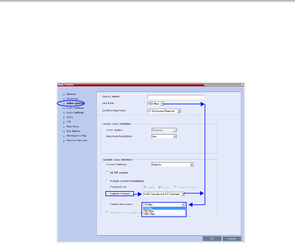
Polycom® RealPresence Collaboration ServerVirtual Edition Administrator’s Guide
3-12 Polycom, Inc.
Enabling H.264 Cascade and SVC Optimized Content Sharing in AVC CP Conferences
When H.264 Cascade and SVC Optimized is selected as the Content Protocol, an additional
field, Content Resolution is displayed in the Content Video Definition pane.
In SVC Conferencing Mode and CP and SVC Conferencing Mode, the Content Resolution option
is disabled.
The Content Resolution is a fixed resolution and frame rate for Content sharing in a Cascaded
Conference. The Content Resolution that are available for selection are dependent on the Line
Rate and Content Settings that have been selected for the conference.
The following table summarizes the interaction of these parameters.
The selection of the appropriate Content Resolution option, when several options are
available, should be based on the line rate and capabilities that can be used by most or all
endpoints connecting to the conference.
Examples:
• If the conference Line Rate is 1024 kbps.
and
•If the Content Settings selection is Graphics.
—Content Resolutions of HD720/5 and HD1080/15 are selectable with 256 kbps and
768 kbps allocated as the Conference Content Rate respectively.
The higher Content Resolution, HD1080/15 should be selected only if most of the
endpoints connecting to the conference can support a Content Rate of 768Kbps,
which requires the participant to connect to the conference at a Line Rate of
1024kbps.
CP
Conferencing
Mode

Chapter 3-Additional Conferencing Information
Polycom, Inc. 3-13
When the lower Content Resolution HD720/5 is selected, the conference Content Rate
is set to 256 kbps. This will enable the endpoints that connect to the conference at a
Line Rate of at least 768 kbps to receive content in the Content channel. Endpoints
that connect to the conference at a line rate lower than 768Kbps, will not receive
content.
•If the Content Settings selection is Hi Resolution Graphics.
—Only HD720/5 can be selected as the Content Resolution with 384 kbps allocated as
the conference Content Rate.
Only endpoints that connect at a Line Rate of 768 kbps that is required to support a
Content Rate of 384 kbps will receive content in the Content channel. Endpoints that
connect to the conference at a line rate lower than 768 kbps, will not receive
content.
•If the Content Settings selection is Live Video.
HD720/5, HD720/30 or HD1080/15 can be selected as the Content Resolution with
768 kbps allocated the as the Conference Content Rate. The higher Content Resolution
should be selected according to the resolution capabilities of the majority of the
endpoints connecting to the conference. Endpoints that cannot support the selected
Content Resolution are considered Legacy Endpoints and will not receive content.
Selecting a Customized Content Rate in AVC CP Conferences
Customized Content Rate functionality can be implemented when a Conference Content Rate,
that is automatically calculated by the Collaboration Server, may not be suitable in a
Cascaded Environment, where conference line rates may vary widely between the cascaded
conferences. For example, one conference may have a line rate of 2 Mbps, and the other a
line rate of is 512kbps.
Guidelines:
• Cascaded conferences may have different Conference Line Rates.
•The Customized Content Rate must be the same for all cascaded conferences.
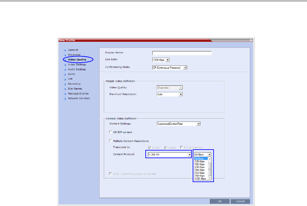
Polycom® RealPresence Collaboration ServerVirtual Edition Administrator’s Guide
3-14 Polycom, Inc.
To Select the Customized Content Rate:
Customized Content Rate is enabled in the Profile - Video Quality dialog box.
1In the Content Settings list, select Customized Content Rate.
When selected, a drop-down menu of the available Conference Content Rates is
displayed. These Content Line Rates are based on and will vary according to the selected
Conference Line Rate.
The largest selectable Content Line Rate is 66% of the Conference Line Rate.
If the Conference Line Rate is 64kbps or 96kbps, the only available Conference Content Rate
is 0, indicating that Content is not supported at these rates.
2Select the required content rate.
When selecting a Conference Line Rate (after selecting Customized Content Rate) that is too
low for the selected Customized Content Rate, the following error message is displayed:
“The selected content line rate should be modified. To update content line rate press Cancel. To
return to automatic mode (Graphics) press OK.”
You can then modify either the Content Line Rate or the Conference Line Rate or select
another Content Setting option.
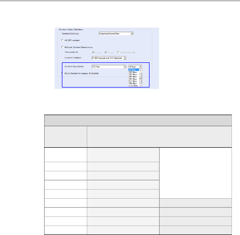
Chapter 3-Additional Conferencing Information
Polycom, Inc. 3-15
3If H.264 Cascade and SVC Optimized is the selected Content Protocol, a Content
Resolution must be selected.
Table 3-7 lists the Cascade Resolutions available for the various Conference Content Rates.
.
*The default resolution for all Content Rates is HD720p5.
Exclusive Content Mode
Exclusive Content Mode allows you to limit Content broadcasting to one participant, preventing
other participants from interrupting the Content broadcasting while it is active.
Guidelines
•Exclusive Content Mode is available in all Conferencing Modes.
Table 3-7 H.264 Cascade and SVC Optimized - Cascade Resolutions
H.264 Cascade Optimized
Conference
Content Rate
(Kbps)
Available Resolutions*
64 HD720p5
Content Not Supported
128 HD720p5
192 HD720p5
256 HD720p5
384 HD720p5
512 HD720p5 HD720p30
768 HD720p5 HD720p30
1152 HD720p5 HD720p30
1536 HD720p5 HD720p30
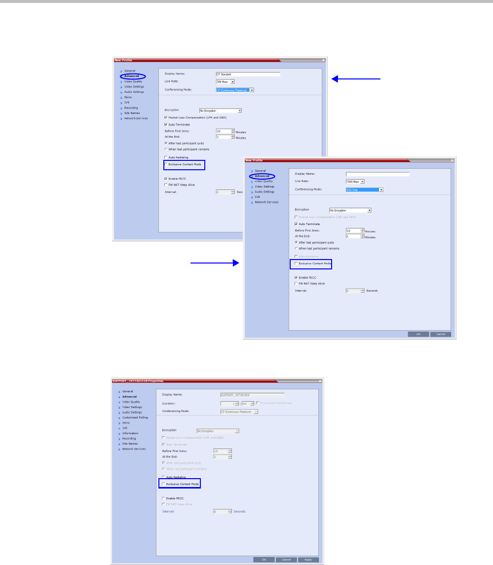
Polycom® RealPresence Collaboration ServerVirtual Edition Administrator’s Guide
3-16 Polycom, Inc.
•The Exclusive Content Mode is enabled or disabled by a check box in the in the Advanced
tabs of the Conference Profile. The check box is cleared (feature is disabled) by default.
•Exclusive Content Mode can be enabled or disabled during an ongoing conference using
the Conference Properties - Advanced dialog box.
•In Exclusive Content Mode, if the RESTRICT_CONTENT_BROADCAST _
TO_LECTURER System Flag is set to:
—NO - the first participant to send content becomes the Content Token holder and has
to release the Content Token before any other participant can acquire the token and
begin transmitting Content.
AVC CP and CP and
SVC Conference
Profile - Advanced
SVC Conference Profile -
Advanced
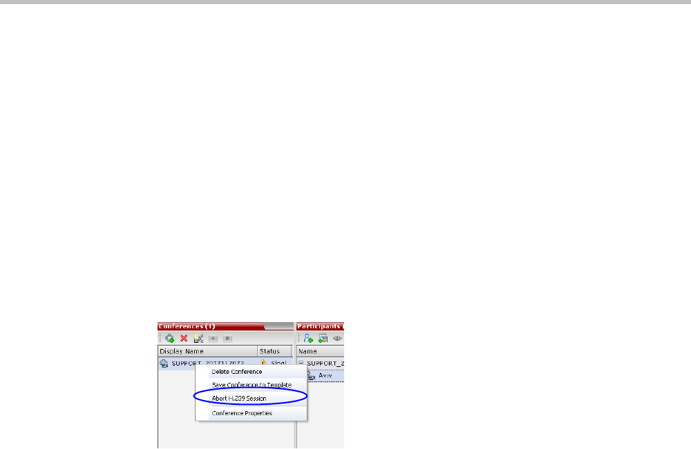
Chapter 3-Additional Conferencing Information
Polycom, Inc. 3-17
—YES - only the designated Lecturer can be the Content Token holder.
•In Exclusive Content Mode, if an endpoint attempts to send Content a few seconds after
another endpoint sent Content, the Content stream it is receiving is momentarily
interrupted by a slide which is displayed for a few seconds before the normal Content
stream is resumed.
Stopping a Content Session
In some cases, when one participant ends the Content session from his/her endpoint, the
Content token is not released and other participants cannot send Content.
The Collaboration Server User can withdraw the Content token from the current holder and
to return it to the MCU for assignment to other endpoints.
To end the current Content session:
>> In the Conferences list pane, right-click the conference icon and then click Abort H.239
Session.
Content Broadcast Control
Content Broadcast Control prevents the accidental interruption or termination of H.239
Content that is being shared in a conference.
Content Broadcast Control achieves this by giving Content Token ownership to a specific
endpoint via the Collaboration Server Web Client. Other endpoints are not able to send content
until Content Token ownership has been transferred to another endpoint via the Collaboration
Server Web Client.
Guidelines
•Content Broadcast Control is supported in CP conferences.
•Content Broadcast Control is supported in H.323 environments.
• Only the selected Content Token owner may send content and Content Token requests
from other endpoints are rejected.
•Content Token ownership is valid until:
—It is canceled by the Collaboration Server User via the Collaboration Server Web
Client.
—The owner releases it.
—The endpoint of the Content Token owner disconnects from the conference.
• The Collaboration Server User can cancel Content Token ownership.
• In cascaded conferences, a participant functioning as the cascade link cannot be given
token ownership.
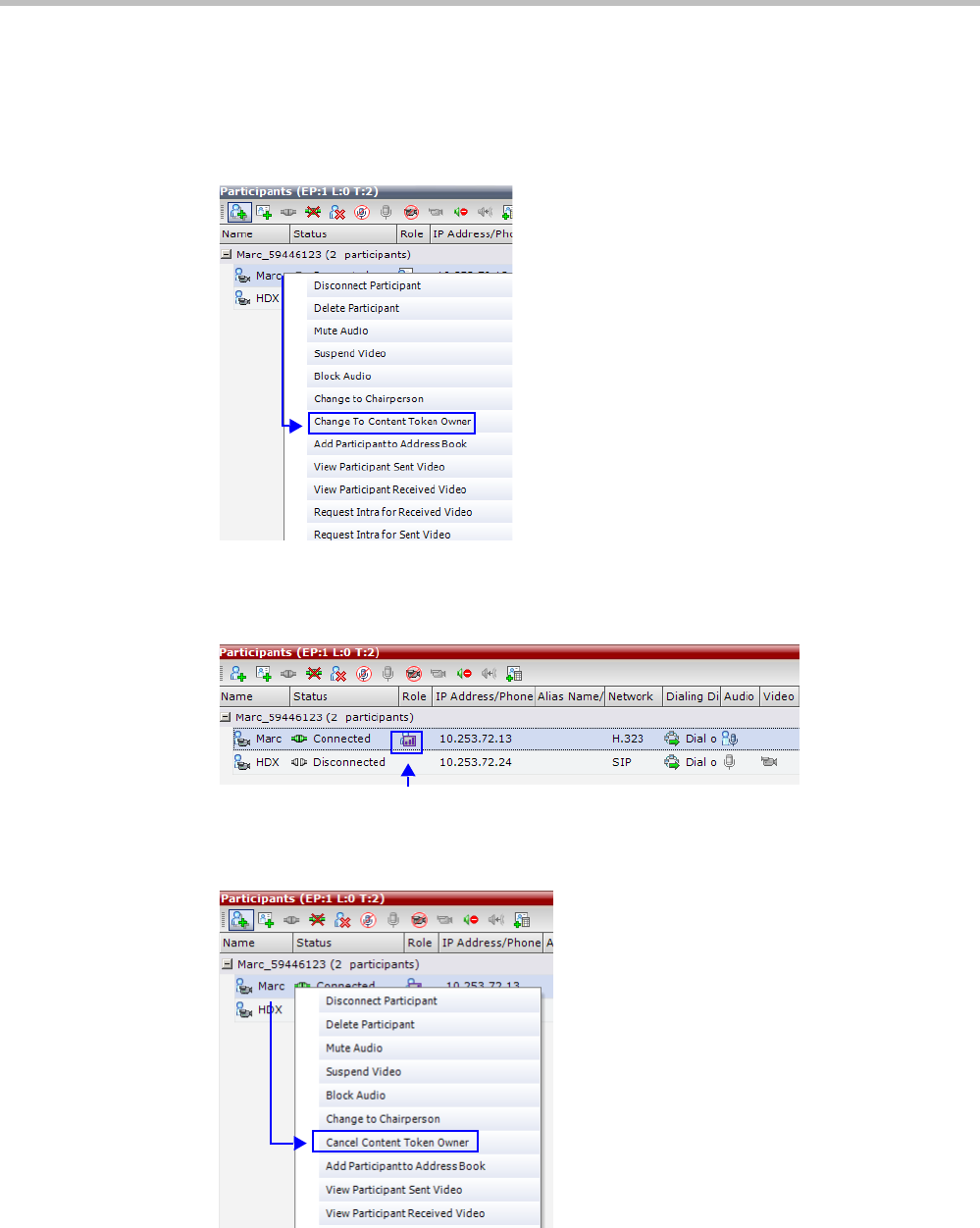
Polycom® RealPresence Collaboration ServerVirtual Edition Administrator’s Guide
3-18 Polycom, Inc.
Giving and Cancelling Token Ownership (AVC Participants)
To give token ownership:
1In the Participants list, right click the AVC-enabled endpoint that is to receive Content
Token ownership.
2Select Change To Content Token Owner in the drop-down menu.
The endpoint receives ownership of the Content Token and an indication icon is
displayed in the Role column of the participant’s entry in the Participants list.
To cancel token ownership:
1In the Participants list, right click the endpoint that currently has Content Token
ownership.

Chapter 3-Additional Conferencing Information
Polycom, Inc. 3-19
2Select Cancel Content Token Owner in the drop-down menu.
Content Token ownership is cancelled for the endpoint.
Managing Noisy Content Connections
The system can identify participants who send frequent requests to refresh their Content
display usually as a result of a problematic network connection. The frequent refresh
requests cause frequent refresh of the Content display and degrade the viewing quality.
When the system identifies the noisy participants, the system will automatically suspend
the requests to refresh the sent Content to avoid affecting the quality of the Content viewed
by other conference participants. This process is controlled by System flags.
Content Display Flags
•MAX_INTRA_REQUESTS_PER_INTERVAL_CONTENT
Enter the maximum number of refresh (intra) requests for the Content channel sent by
the participant’s endpoint in a 10 seconds interval that will be dealt by the
Collaboration Server system. When this number is exceeded, the Content sent by this
participant will be identified as noisy and his/her requests to refresh the Content
display will be suspended.
Default setting: 3
•MAX_INTRA_SUPPRESSION_DURATION_IN_SECONDS_CONTENT
Enter the duration in seconds to ignore the participant’s requests to refresh the Content
display.
Default setting: 10
•CONTENT_SPEAKER_INTRA_SUPPRESSION_IN_SECONDS
This flag controls the requests to refresh (intra) the Content sent from the Collaboration
Server system to the Content sender as a result of refresh requests initiated by other
conference participants.
Enter the interval in seconds between the Intra requests sent from the Collaboration
Server to the endpoint sending the Content to refresh the Content display. Refresh
requests that will be received from endpoints within the defined interval will be
postponed to the next interval.
Default setting: 5
Forcing Other Content Capabilities
•The H239_FORCE_CAPABILITIES System Flag in system.cfg gives additional control
over Content sharing:
—When the flag is set to NO (default), the Collaboration Server only verifies that the
endpoint supports the content protocols: H.263 or H.264.
—When set to YES, the Collaboration Server checks frame rate, bit rate, resolution,
annexes and all other parameters of the Content mode as declared by an endpoint
during the capabilities negotiation phase. If the endpoint does not support the
Content capabilities of the MCU, the participant will not be able to send or receive
content over a dedicated content channel.

Polycom® RealPresence Collaboration ServerVirtual Edition Administrator’s Guide
3-20 Polycom, Inc.
Content Sharing via the Polycom CCS Plug-in for Microsoft Lync Clients
From version 8.1, Polycom CCS (Content Collaboration Solution) Plug-in for Lync clients
allows Lync clients to receive and send Content on a separate channel, without having to use
the video channel. Content is transmitted using SIP BFCP.
For more information, see Appendix 3, “Exclusive Content Mode”on page 3-15.
Video Preview (AVC Only Participants)
Collaboration Server users can preview the video sent from the participant to the conference
(MCU) and the video sent from the conference to the participant. It enables the
Collaboration Server users to monitor the quality of the video sent and received by the
participant and identify possible quality degradation.
The video preview is displayed in a separate window independent to the Collaboration Server
Web Client. All Web Client functionality is enabled and conference and participant
monitoring as well as all other user actions can be performed while the video preview
window is open and active. Live video is shown in the preview window as long as the
window is open. The preview window closes automatically when the conference ends or
when participant disconnects from the conference. It can also be closed manually by the
Collaboration Server user.
Video Preview Guidelines
• Video preview is available for AVC participants. It is not available for SVC participants.
• Video preview window size and resolution are adjusted to the resolution of the PC that
displays the preview.
• Video Preview of the video sent from the conference to the participant is shown
according to the line rate and video parameters of the level threshold to which the
participant is connected.
• All users can view a video preview.
• Only one preview window can be displayed for each Collaboration Server Web Client
connection (workstation).
• Only one preview window can be displayed for a single conference and up to four
preview windows can be displayed for each system on different workstations (one per
workstation and one per conference).
• Live video that is shown in the preview window does not include the Content when it
is sent by the participant.
• Video Preview is supported in cascaded conferences.
• If the video preview window is opened when the IVR slide is displayed to the
participant, it will also be displayed in the video preview window.
• Video Preview is supported with H.264 High Profile.
• Video Preview is not supported for endpoints using the RTV protocol.
• Video Preview is disabled in encrypted conferences.
• Video preview cannot be displayed when the participant’s video is suspended.
• Participant’s video preview and the CMAD window cannot be open and running
simultaneously on the same PC as both require the same DirectDraw resource.
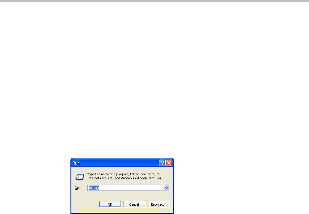
Chapter 3-Additional Conferencing Information
Polycom, Inc. 3-21
Workstation Requirements
To be able to display the video preview window, the following minimum requirements
must be met:
• Windows XP, Windows Vista and Windows 7
• Internet Explorer 7 and later
• DirectX is installed
• DirectDraw Acceleration must be enabled and no other application is using the video
resource
• Hardware acceleration must be enabled
Testing your Workstation
To ensure that your workstation can display the video preview window:
1In Windows, click Start > Run.
The Run dialog box opens.
2In the Open field, type dxdiag and press the Enter key or click OK.
A confirmation message is displayed.
3Click Yes to run the diagnostics.
The DirectX Diagnostic Tool dialog box opens.
4Click the Display tab.
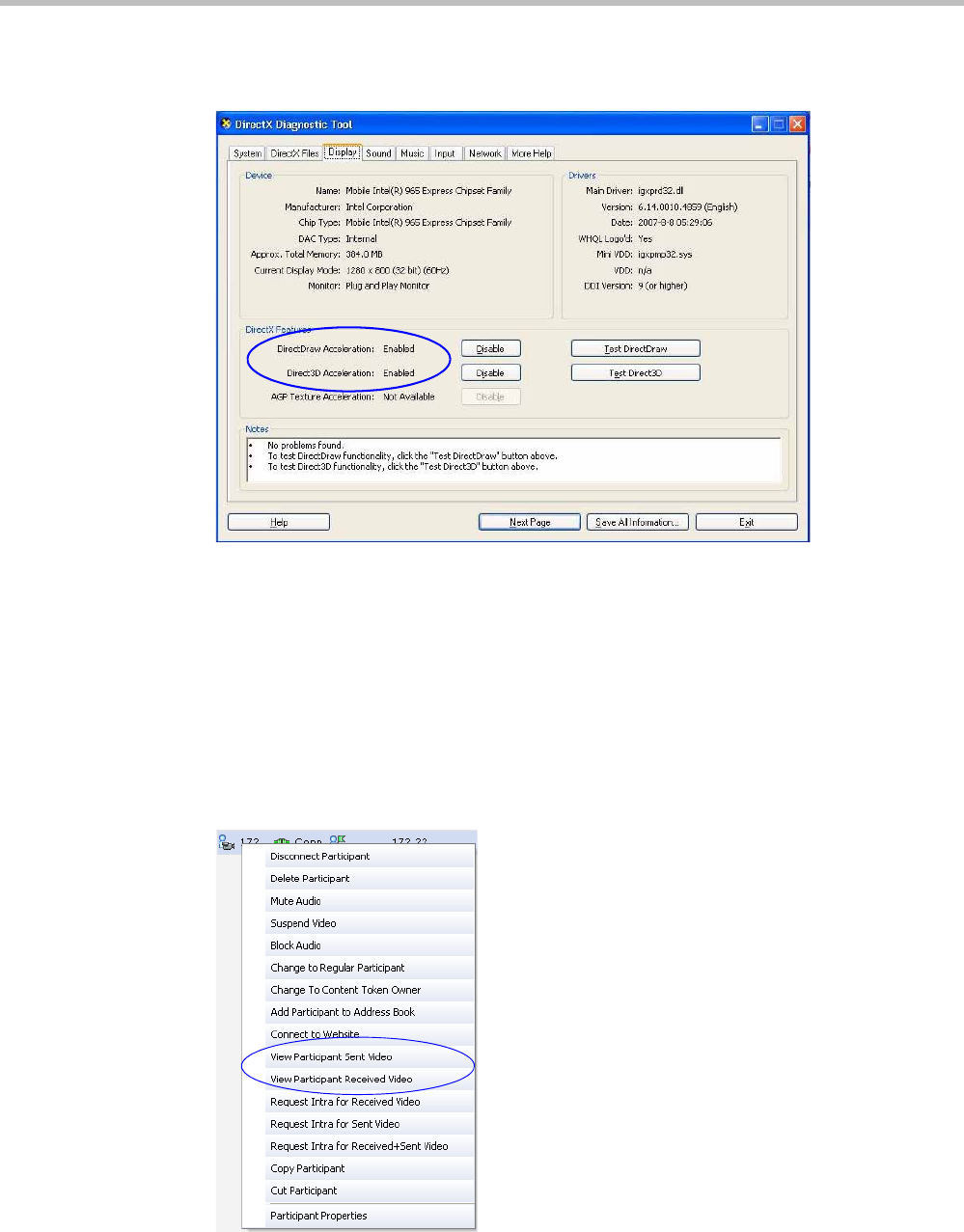
Polycom® RealPresence Collaboration ServerVirtual Edition Administrator’s Guide
3-22 Polycom, Inc.
To be able to display the video preview window, the DirectDraw Acceleration and
Direct3D Acceleration options must be Enabled.
If the video card installed in the PC does not support DirectDraw Acceleration, a black
window may be viewed in the Video Preview window.
5Click the Exit button.
Previewing the Participant Video
To preview the participant video:
1List the conference participants in the Participants pane.
2Right-click the participant whose video you want to preview and then click one of the
following options:
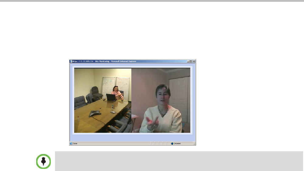
Chapter 3-Additional Conferencing Information
Polycom, Inc. 3-23
—View Participant Sent Video - to display the video sent from the participant to the
conference.
—View Participant Received Video - to display the video sent from the conference
to the participant.
The Video Preview window opens.
Auto Scan and Customized Polling in Video Layout (CP Only)
Auto Scan enables a user to define a single cell in the conference layout to cycle the display of
participants that are not in the conference layout.
Customized Polling allows the cyclic display to be set to a predefined order for a predefined
time period. The cyclic display only occurs when the number of participants is larger than
the number of cells in the layout.
Guidelines
•Auto Scan and Customized Polling are supported in AVC CP conferences only.
• Participants that are in the conference layout will not appear in the Auto Scan enabled
cell.
•If Customized Polling is not used to define the order of the Auto Scan it will proceed
according to order in which the participants connected to the conference.
• If the user changes the conference layout, the Auto Scan settings are not exported to the
new layout. If the user changes the conference layout back to the layout in which Auto
Scan was enabled, Auto Scan with the previous settings will be resumed.
If the video card installed in the PC does not support DirectDraw Acceleration, a black window may
be viewed.
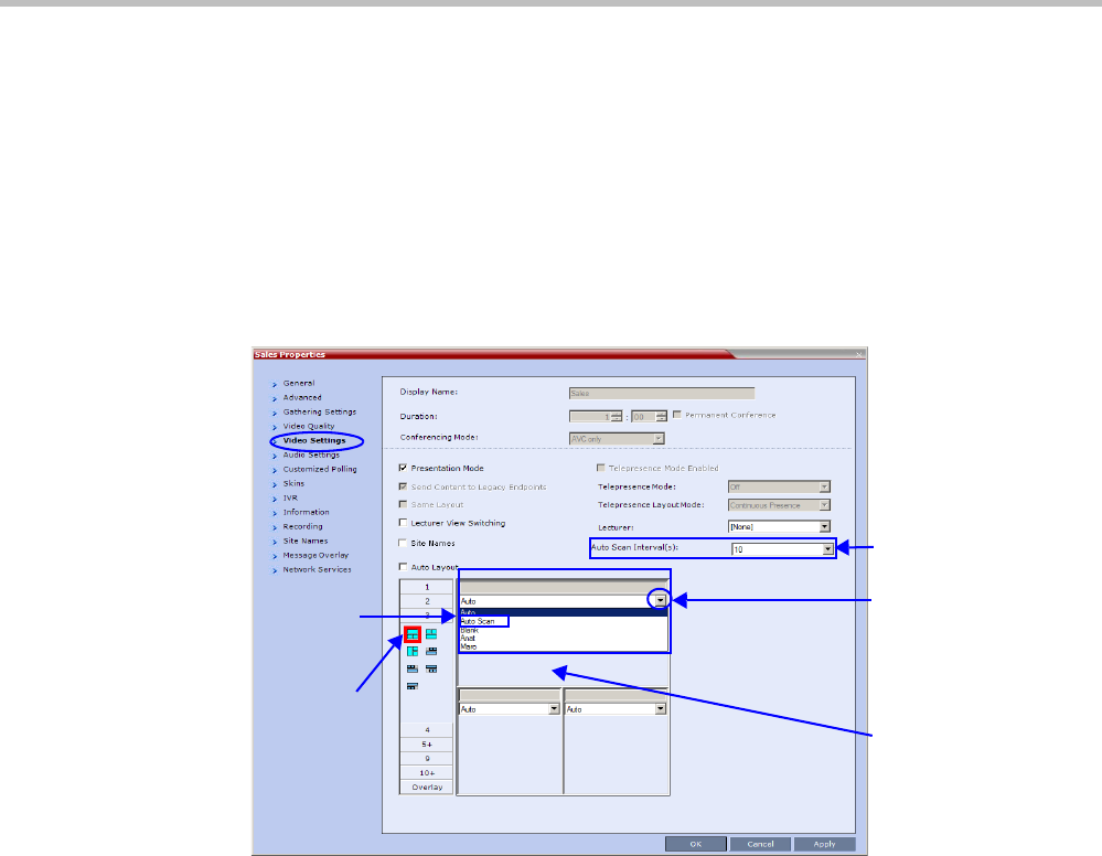
Polycom® RealPresence Collaboration ServerVirtual Edition Administrator’s Guide
3-24 Polycom, Inc.
Enabling Auto Scan and Customized Polling (CP Only)
Auto Scan
To enable Auto Scan:
1In the Collaboration Server Web Client Main Screen - Conference list pane, double-click the
conference or right-click the conference and then click Conference Properties.
2In the Conference Properties - General dialog box, click Video Settings.
The Video Settings tab is displayed.
3If Auto Layout check box is selected, clear it.
4In the video layout cell to be designated for Auto Scan, click the drop-down menu
button and select Auto Scan.
5Select from the Auto Scan Interval(s) drop-down list the scanning interval in seconds.
6Click the Apply button to confirm and keep the Conference Properties dialog box open.
-or-
Click OK to confirm and close the Conference Properties dialog box.
Customized Polling
The order in which the Auto Scanned participants are displayed in the Auto Scan enabled
cell of the video layout can be customized.
1Open the Customized Polling tab:
aIf the Video Settings tab is open click the Customized Polling tab.
or
bIn the Conference list pane, double-click the conference or right-click the conference
and then click Conference Properties.
Drop Down
Menu Button
Selected
Video Layout
Cell
Auto Scan
Option
Selected
Video Layout
Auto Scan
Interval(s)

Chapter 3-Additional Conferencing Information
Polycom, Inc. 3-25
cIn the Conference Properties - General dialog box, click Customized Polling.
The Customized Polling tab is displayed.
All conference participants are listed in the left pane (All Participants) while the
participants that are to be displayed in the Auto Scan enabled cell of the video layout
are listed in the right pane (Scanning Order).
The dialog box buttons are summarized in the following table:
2Optional. Add a participant to the list of participants to be Auto Scanned:
—Click on the participant’s name in the All Participants list and then click the Add
button to move the participant to the Scanning Order pane.
3Optional. Delete a participant from the list of participants to be Auto Scanned:
—Click on a participant’s name in the Scanning Order list and then click the Delete
button to move the participant back to the All Participants pane.
4Optional. Add all participants to the list of participants to be Auto Scanned by clicking
the Add All button.
5Optional. Delete all participant from the list of participants to be Auto Scanned by
clicking the Delete All button.
6Optional. Move the participant up in the Scanning Order by clicking the Up button.
7Optional. Move the participant down in the Scanning Order by clicking the Down
button.
8Click the Apply button to confirm and keep the Conference Properties dialog box open, or
click the OK the button to confirm and return to the Collaboration Server Web Client Main
Screen.
Button Description
Add Select a participant and click this button to Add a the participant to
the list of participants to be Auto Scanned.
The participants name is removed from the All Participants pane.
Delete Select a participant and click this button to Delete the participant
from the list of participants to be Auto Scanned.
The participants name is moved back to the All Participants pane.
Add All Add all participants to the list of participants to be Auto Scanned.
All participants’ names are removed from the All Participants pane.
Delete All Delete all participant from the list of participants to be Auto
Scanned.
All participants’ names are moved back to the All Participants pane.
Up Select a participant and click this button to move the participant Up
in the Scanning Order.
Down Select a participant and click this button to move the participant
Down in the Scanning Order.

Polycom® RealPresence Collaboration ServerVirtual Edition Administrator’s Guide
3-26 Polycom, Inc.
Media Encryption
Encryption is available at the conference and participant levels, based on AES 128
(Advanced Encryption Standard) and is fully H.233/H.234 compliant and the Encryption
Key exchange DH 1024-bit (Diffie-Hellman) standards.
Media Encryption Guidelines
• Encryption is not available in all countries and it is enabled in the MCU license. Contact
Polycom Support to enable it.
• Media encryption is supported in CP, SVC Only and mixed CP and SVC Conferencing
Modes.
• Endpoints must support both AES 128 encryption and DH 1024 key exchange
standards which are compliant with H.235 (H.323) to encrypt and to join an encrypted
conference.
• The encryption mode of the endpoints is not automatically recognized, therefore the
encryption mode must be set for the conference or the participants (when defined).
• Conference level encryption must be set in the Profile, and cannot be changed once the
conference is running.
• If an endpoint connected to an encrypted conference stops encrypting its media, it is
disconnected from the conference.
• In Cascaded conferences, the link between the cascaded conferences must be encrypted
in order to encrypt the conferences.
• The recording link can be encrypted when recording from an encrypted conference to
the RSS that is set to encryption. For more information, see "Recording Link Encryption”
on page 13-7.
• Encryption of SIP Media is supported using SRTP (Secured Real-time Transport Protocol)
and the AES key exchange method.
• Encryption of SIP Media requires the encryption of SIP signaling - TLS Transport Layer
must be used.
• Encryption of SIP Media is supported in conferences as follows:
—All media channels are encrypted: video, audio and FECC.
—Collaboration Server SRTP implementation complies with Microsoft SRTP
implementation.
—LPR is not supported with SRTP.
—The ENABLE_SIRENLPR_SIP_ENCRYPTION System Flag enables the SirenLPR
audio algorithm when using encryption with the SIP protocol. The default value of
this flag is NO meaning SirenLPR is disabled by default for SIP participants in an
encrypted conference. To enable SirenLPR the System Flag must be added to
system.cfg and its value set to YES.
—The SEND_SRTP_MKI System Flag enables or disables the inclusion of the MKI
field in SRTP packets sent by the Collaboration Server. The default value of the flag
is YES.
Add the flag to system.cfg and set its value set to NO to disable the inclusion of the MKI
field in SRTP packets sent by the Collaboration Server when using endpoints that
cannot decrypt SRTP-based audio and video streams if the MKI (Master Key Identifier)
field is included in SRTP packets sent by the Collaboration Server. When all conferences

Chapter 3-Additional Conferencing Information
Polycom, Inc. 3-27
on the RMX will not have MS-Lync clients participating and will have 3rd party
endpoints participating. This setting is recommended for Maximum Security
Environments.
Add the flag to system.cfg and set its value set to YES when Microsoft Office
Communicator and Lync Clients. When any conferences on the RMX will have both MS-
Lync clients and Polycom endpoints participating. Some 3rd party endpoints may be
unsuccessful in participating in conferences with this setting.
Polycom endpoints function normally regardless of the setting of this flag.
For more information, see "Modifying System Flags” on page 20-1.
Mixing Encrypted and Non-encrypted Endpoints in one Conference
Mixing encrypted and non-encrypted endpoints in one conference is possible, based on the
Encryption option “Encrypt When Possible” in the Conference Profile - Advance dialog box.
The option “Encrypt When Possible” enables the negotiation between the MCU and the
endpoints and let the MCU connect the participants according to their capabilities, where
encryption is the preferred setting. Defined participants that cannot connect encrypted are
connected non-encrypted, with the exception of dial-out SIP participants.
The same system behavior can be applied to undefined participants, depending on the
setting of the System Flag
FORCE_ENCRYPTION_FOR_UNDEFINED_PARTICIPANT_IN_WHEN_AVAILABLE_MODE:
• When set to NO and the conference encryption in the Profile is set to “Encrypt When
Possible”, both Encrypted and Non-encrypted undefined participants can connect to the
same conferences, where encryption is the preferred setting.
• When set to YES (default), Undefined participants must connect encrypted, otherwise
they are disconnected.
For defined participants, connection to the conference is decided according to the encryption
settings in the conference Profile, the Defined Participant’s encryption settings.
For undefined participants, connection to the conference is decided according to the
encryption settings in the conference Profile, the System Flag setting and the connecting
endpoint’s Media Encryption capabilities.
•When the conference encryption is set to "Encrypt when possible", SIP dial out participants
whose encryption is set to AUTO can only connect with encryption, otherwise they are
disconnected from the conference.
When the conference encryption is set to "Encrypt when possible", SIP dial out participants whose
encryption is set to AUTO can only connect with encryption, otherwise they are disconnected from
the conference.

Polycom® RealPresence Collaboration ServerVirtual Edition Administrator’s Guide
3-28 Polycom, Inc.
Direct Connection to the Conference
Table 3-8, summarizes the connection status of participants, based on the encryption
settings in the conference Profile, the Defined Participant’s encryption settings or the System
Flag setting for undefined participants and the connecting endpoint’s Media Encryption
capabilities.
* System Flag = FORCE_ENCRYPTION_FOR_UNDEFINED_PARTICIPANT_IN_WHEN_AVAILABLE_MODE
Table 3-8 Connection of Defined and Undefined H.323, SIP Participants to the Conference Based
on the Encryption Settings
Conference
Encryption
Setting
Defined Participant Undefined Participant
Encryption
Setting Connection status
Connection
Status
*Flag = No
Connection
Status
*Flag = YES
No
Encryption
Auto Connected,
non-encrypted
Connected
non-encrypted
(Encryption is not
declared by the
Collaboration
Server, therefore
the endpoint does
not use
encryption)
Connected
non-encrypted
(Encryption is not
declared by the
Collaboration
Server, therefore
the endpoint does
not use
encryption)
No Connected,
non-encrypted
Yes Connected only if
encrypted.
Non-encrypted endpoints
are disconnected as
encryption is forced for the
participant.
Encrypt All Auto Connected, encrypted.
Non-encrypted endpoints
are disconnected
Connect only if
encrypted.
Non-encrypted
endpoints are
disconnected
Connect only if
encrypted.
Non-encrypted
endpoints are
disconnected
No Disconnected (cannot be
added to the conference)
Yes Connected, encrypted
Encrypt
When
Possible
Auto All defined participants
except dial-out SIP
participants: Connect
encrypted - Endpoints with
encryption capabilities.
Connect non-encrypted -
endpoints without
encryption capabilities.
Defined dial-out SIP
participant: Connect only if
encrypted.
Non-encrypted endpoints
are disconnected.
Connect
encrypted -
Endpoints with
encryption
capabilities.
Connect non-
encrypted -
endpoints without
encryption
capabilities
Connect only if
encrypted.
Non-encrypted
endpoints are
disconnected.
No Connected, non-encrypted
Yes Connected, encrypted

Chapter 3-Additional Conferencing Information
Polycom, Inc. 3-29
Connection to the Entry Queue
An undefined participant connecting to an Entry Queue inherits the encryption
characteristics of the Entry Queue as defined in the Entry Queue’s profile.
Participants can be moved from the Entry Queue and the destination conference if both
conferencing entities have the same Profile settings, i.e. from SVC Only Entry Queue to SVC
Only conference and from mixed CP and SVC Entry Queue to a mixed CP and SVC
conference, etc.
Table 3-9 summarizes the connection possibilities for a participant that is to be moved from
an Entry Queue to a destination conference for each of the conference Profile and Entry
Queue encryption options.
* System Flag = FORCE_ENCRYPTION_FOR_UNDEFINED_PARTICIPANT_IN_WHEN_AVAILABLE_MODE
Moving from the Entry Queue to Conferences or Between Conferences
Participants can be moved from the Entry Queue and the destination conference if both
conferencing entities have the same Profile settings, i.e. from SVC Only Entry Queue to SVC
Only conference and from mixed CP and SVC Entry Queue to a mixed CP and SVC
conference, etc.
Table 3-9 Connection of Undefined Participants to the Entry Queue Based on the Encryption
Settings
Entry Queue
Encryption Setting
Undefined Participant Connection to the Entry Queue
*Flag = No *Flag = YES
No Encryption Connected, non-encrypted
(Encryption is not declared by the
Collaboration Server, therefore
endpoint does not use encryption)
Connected, non-encrypted
(Encryption is not declared by the
Collaboration Server, therefore
endpoint does not use encryption)
Encrypt All Connected only if encrypted.
Non-encrypted endpoints are
disconnected
Connected only if encrypted.
Non-encrypted endpoints are
disconnected
Encrypt When
Possible
Connected encrypted - Endpoints
with encryption capabilities.
Connected non-encrypted -
endpoints without encryption
capabilities
Connected only if encrypted.
Non-encrypted endpoints are
disconnected.
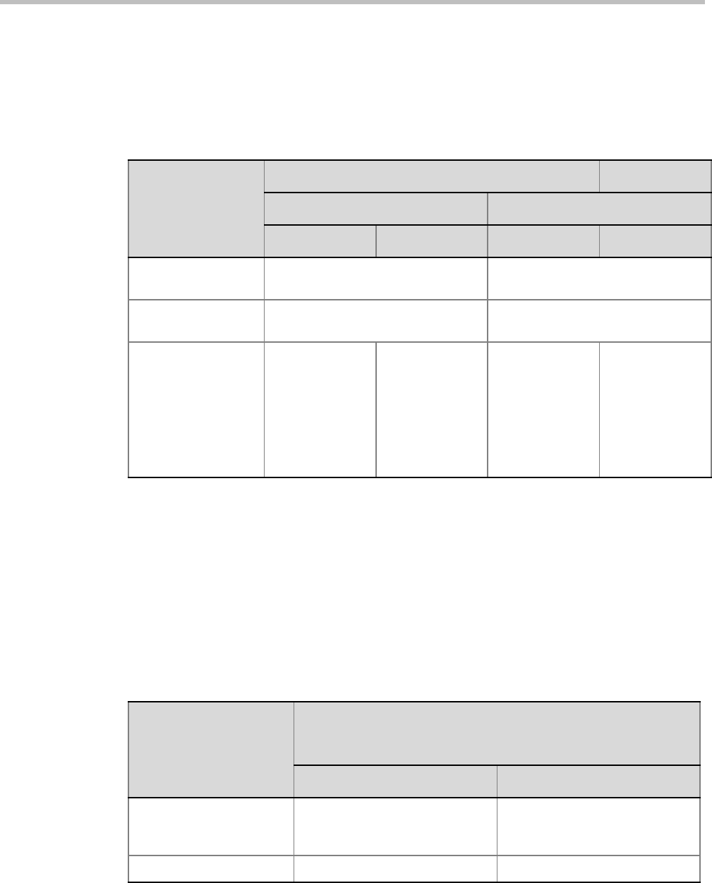
Polycom® RealPresence Collaboration ServerVirtual Edition Administrator’s Guide
3-30 Polycom, Inc.
When moving participants from the Entry Queue to the destination conference, or when the
Collaboration Server user moves AVC participants from one conference to another (SVC
participants cannot be moved between conferences), the connection rules are similar and
they are summarized in Table 3-10:
* System Flag = FORCE_ENCRYPTION_FOR_UNDEFINED_PARTICIPANT_IN_WHEN_AVAILABLE_MODE
Recording Link Encryption
Recording Links are treated as regular participants, however the
ALLOW_NON_ENCRYPT_RECORDING_LINK_IN_ENCRYPT_CONF System Flag must
be set to YES if a non-encrypted Recording Link is to be allowed to connect to an encrypted
conference.
Table 3-11 summarizes the connection possibilities for a Recording Link that is to be
connected to a conference for each of the conference profile and Entry Queue encryption
options.
Table 3-10 Moving Participants from the Entry Queue to the Destination conference or between
conferences Based on the Encryption Settings
Destination
Conference
Encryption Setting
Current Participant Encryption Status
Encrypted Non-Encrypted
*Flag = NO *Flag = YES *Flag = NO *Flag = YES
No Encryption Move succeeds, connected
encrypted
Move succeeds, connected non-
encrypted
Encrypt All Move succeeds, connected
encrypted.
Move fails, disconnected.
Encrypt When
Possible
Move succeeds,
connected
encrypted
Move succeeds,
connected
encrypted
Move succeeds,
connected non-
encrypted
Connected only
if endpoint was a
defined
participant in the
source
conference.
Otherwise, move
fails.
Table 3-11 Connections by Recording Link and Conference Encryption Settings
Conference
Profile Setting
Recording Link Connection Status according to flag:
ALLOW_NON_ENCRYPT_RECORDING_
LINK_IN_ENCRYPT_CONF
YES NO
Encrypt All
Connected encrypted if possible,
otherwise connected non-
encrypted.
Connected only if encrypted,
otherwise disconnected
No Encryption Connected non-encrypted Connected non-encrypted

Chapter 3-Additional Conferencing Information
Polycom, Inc. 3-31
Encryption Flag Settings
To modify the Encryption flags:
1Click Setup>System Configuration.
The System Flags dialog box opens.
2Set the
FORCE_ENCRYPTION_FOR_UNDEFINED_PARTICIPANT_IN_WHEN_AVAILA
BLE_MODE flag to YES or NO.
3If recording will be used in encrypted conferences, set the
ALLOW_NON_ENCRYPT_RECORDING_LINK_IN_ENCRYPT_CONF flag to YES
or NO.
4Click OK.
For more information, see "Modifying System Flags” on page 20-1.
5Reset the MCU for flag changes to take effect.
Encrypt when possible
Connected encrypted if possible,
otherwise connected non-
encrypted.
Connected encrypted if possible,
otherwise connected non-
encrypted.
Table 3-11 Connections by Recording Link and Conference Encryption Settings (Continued)
Conference
Profile Setting
Recording Link Connection Status according to flag:
ALLOW_NON_ENCRYPT_RECORDING_
LINK_IN_ENCRYPT_CONF
YES NO
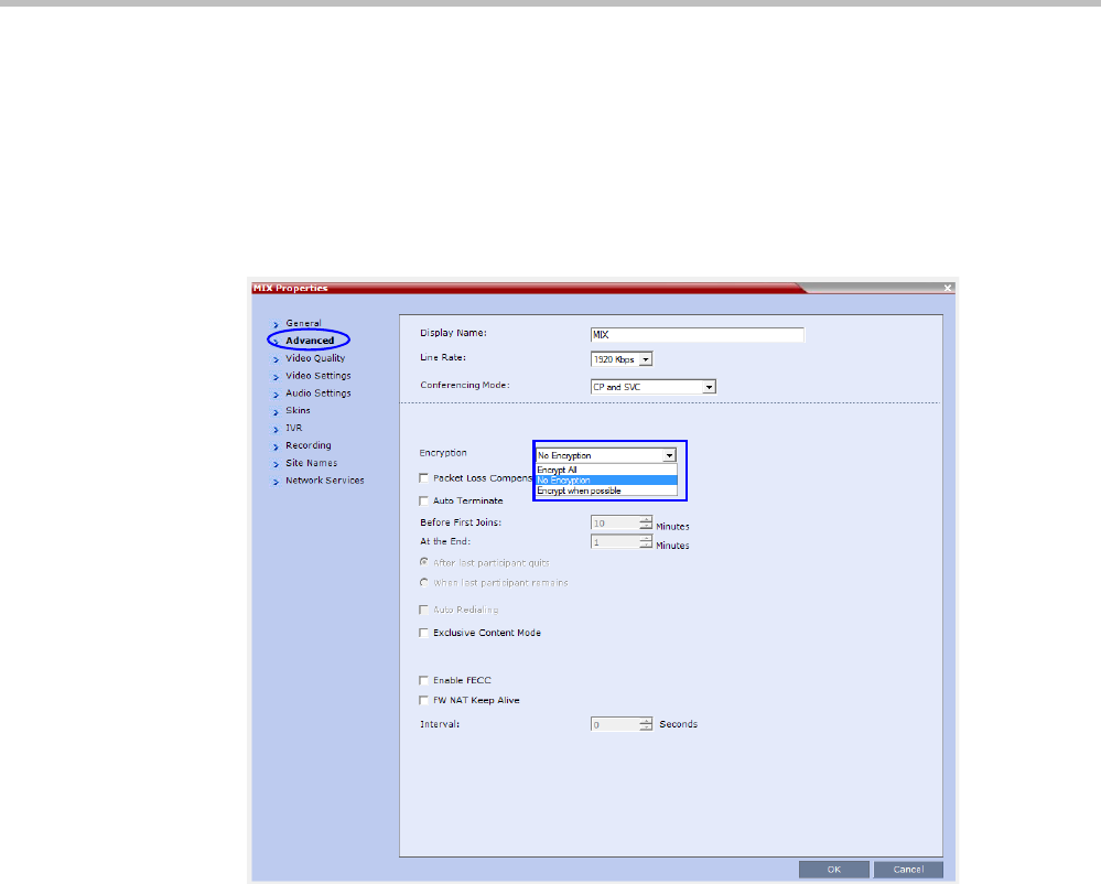
Polycom® RealPresence Collaboration ServerVirtual Edition Administrator’s Guide
3-32 Polycom, Inc.
Enabling Encryption in the Profile
Encryption for the conference is in the Profile and cannot be changed once the conference is
running.
To enable encryption at the conference level:
>> In the Conference Profile Properties – Advanced dialog box, select one of the following
Encryption options:
—Encrypt All - Encryption is enabled for the conference and all conference
participants must be encrypted.
—No Encryption - Encryption is disabled for the conference.
—Encrypt when possible - enables the negotiation between the MCU and the
endpoints and let the MCU connect the participants according to their capabilities,
where encryption is the preferred setting. For connection guidelines see "Mixing
Encrypted and Non-encrypted Endpoints in one Conference” on page 3-27.
For more information about recording encrypted conferences, see "Recording Link
Encryption” on page 13-7.
Enabling Encryption at the Participant Level
You can select the encryption mode for each of the defined participants. Encryption options
are affected by the settings of the flag in the system configuration. Undefined participants
are connected with the Participant Encryption option set to Auto, inheriting the conference/
Entry Queue encryption setting.
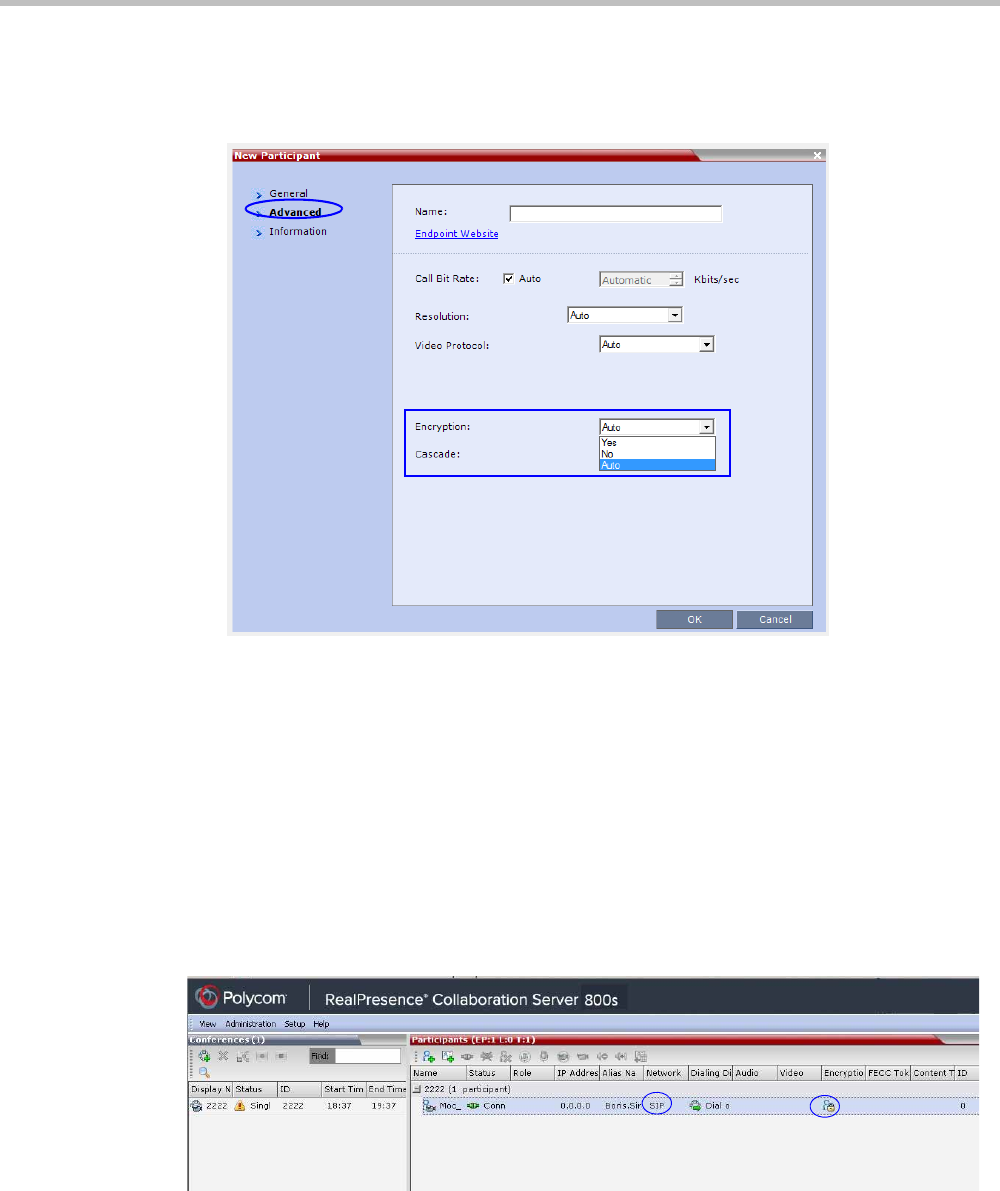
Chapter 3-Additional Conferencing Information
Polycom, Inc. 3-33
To enable encryption at the participant level:
>> In the Participant Properties – Advanced dialog box, in the Encryption list, select one of the
following options: Auto, On, or Off.
—Auto - The participant inherits the conference/Entry Queue encryption setting.
The participant connects as encrypted only if the conference is defined as
encrypted.
—Yes - The participant joins the conference/Entry Queue as encrypted.
—No - The participant joins the conference/Entry Queue as non-encrypted.
Monitoring the Encryption Status
The conference encryption status is indicated in the Conference Properties - General dialog
box.
The participant encryption status is indicated by a check mark in the Encryption column in
the Participants list pane.
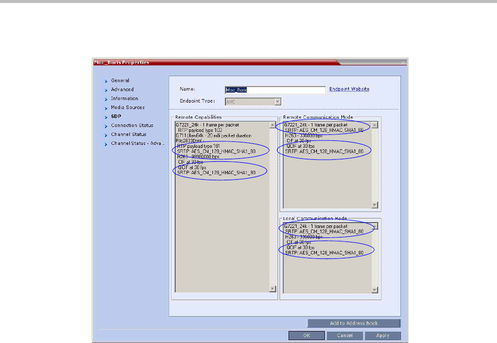
Polycom® RealPresence Collaboration ServerVirtual Edition Administrator’s Guide
3-34 Polycom, Inc.
The participant encryption status is also indicated in the Participant Properties – SDP tab,
where SRTP indication is listed for each encrypted channel (for example, audio and video).
An encrypted participant who is unable to join a conference is disconnected from the
conference. The disconnection cause is displayed in the Participant Properties – Connection
Status tab, Security Failure indication, and the Cause box identifies the encryption related
situation.
For more information about monitoring, see "Conference and Participant Monitoring” on
page 12-1.
Packet Loss Compensation (LPR and DBA) AVC CP
Conferences
Lost Packet Recovery (LPR) and Dynamic Bandwidth Allocation (DBA) help minimize media
quality degradation that can result from packet loss in the network. Packet loss Compensation
is available in AVC CP Conferencing Mode only and is not supported in SVC Conferencing
Mode or CP and SVC Conferencing Mode.
Packet Loss
Packet Loss refers to the failure of data packets, transmitted over an IP network, to arrive at
their destination. Packet Loss is described as a percentage of the total packets transmitted.

Chapter 3-Additional Conferencing Information
Polycom, Inc. 3-35
Causes of Packet Loss
Network congestion within a LAN or WAN, faulty or incorrectly configured network
equipment or faulty cabling are among the many causes of Packet Loss.
Effects of Packet Loss on Conferences
Packet Loss affects the quality of:
•Video – frozen images, decreased frame rate, flickering, tiling, distortion, smearing,
loss of lip sync
•Audio – drop-outs, chirping, audio distortion
•Content – frozen images, blurring, distortion, slow screen refresh rate
Lost Packet Recovery
The Lost Packet Recovery (LPR) algorithm uses Forward Error Correction (FEC) to create
additional packets that contain recovery information. These additional packets are used to
reconstruct packets that are lost, for whatever reason, during transmission. Dynamic
Bandwidth Allocation (DBA) is used to allocate the bandwidth needed to transmit the
additional packets.
Lost Packet Recovery Guidelines
• If packet loss is detected in the packet transmissions of either the video or Content
streams:
—LPR is applied to both the video and Content streams.
—DBA allocates bandwidth from the video stream for the insertion of additional
packets containing recovery information.
•LPR is supported in H.323 and SIP networking environments only.
•In LPR-enabled Continuous Presence conferences:
—Both LPR-enabled and non-LPR-enabled endpoints are supported.
—The LPR process is not applied to packet transmissions from non-LPR-enabled
H.323 and SIP endpoints.
—Non-LPR-enabled endpoints can be moved to LPR-enabled conferences.
—LPR-enabled endpoints cannot be moved to non-LPR-enabled conferences.
• When connecting via an Entry Queue:
—A participant using an LPR-enabled endpoint can be moved to a non-LPR-enabled
conference. The participant is connected with LPR enabled.
Enabling Lost Packet Recovery
LPR is enabled or disabled in the Conference Profile dialog box.
•CP Conferences – LPR is enabled by default in the New Profile – Advanced dialog box.
For more information, see "Defining New Profiles” on page 2-20.
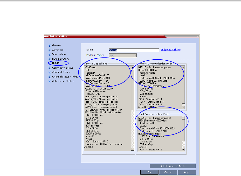
Polycom® RealPresence Collaboration ServerVirtual Edition Administrator’s Guide
3-36 Polycom, Inc.
Monitoring Lost Packet Recovery
In the Participant Properties – H.245 tab, LPR activity is displayed in all three panes.
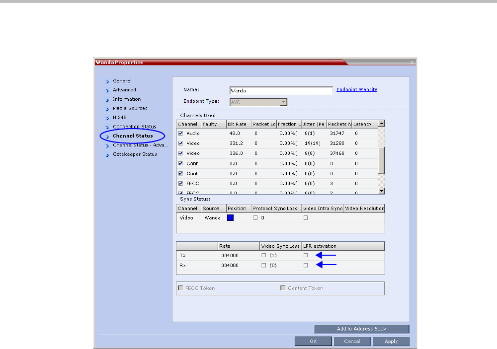
Chapter 3-Additional Conferencing Information
Polycom, Inc. 3-37
In the Participant Properties – Channel Status tab, check box indicators show LPR activation in
the local and remote (transmit and receive) channels.
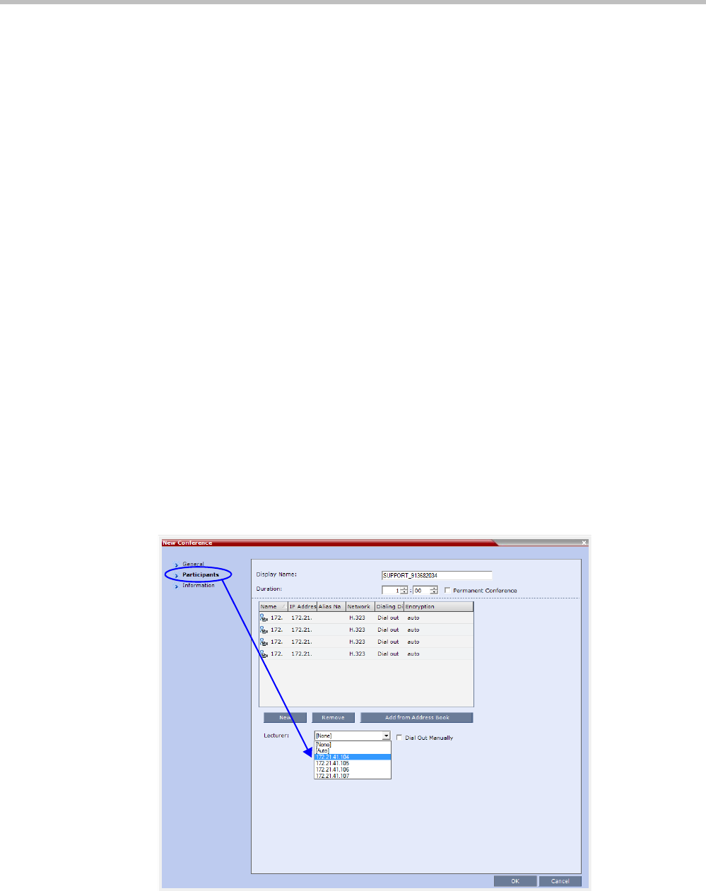
Polycom® RealPresence Collaboration ServerVirtual Edition Administrator’s Guide
3-38 Polycom, Inc.
Lecture Mode (AVC CP Only)
Lecture Mode enables all participants to view the lecturer in full screen while the conference
lecturer sees all the other conference participants in the selected layout while he/she is
speaking. When the number of sites/endpoints exceeds the number of video windows in
the layout, switching between participants occurs every 15 seconds. Conference participants
cannot change their Personal Layouts while Lecture Mode is enabled.
Automatic switching is suspended when one of the participants begins talking, and it is
resumed automatically when the lecturer resumes talking.
Lecture Mode is available only in AVC CP Conferencing Mode.
Enabling Lecture Mode
Lecture Mode is enabled at the conference level by selecting the lecturer. Conference
participants cannot change their Personal Layouts while Lecture Mode is enabled.
Automatic switching between participants viewed on the lecturer’s screen is enabled in the
conference Profile.
Selecting the Conference Lecturer
Selecting a lecturer for the ongoing conference, enables the Lecture Mode. You can select the
lecturer:
• during the definition of the ongoing conference
• after the conference has started and the participants have connected to the conference.
To select the lecturer and enable the Lecture Mode while starting the conference:
>> In the Conference Properties - Participant dialog box, enable the Lecture Mode in one of
the following methods:
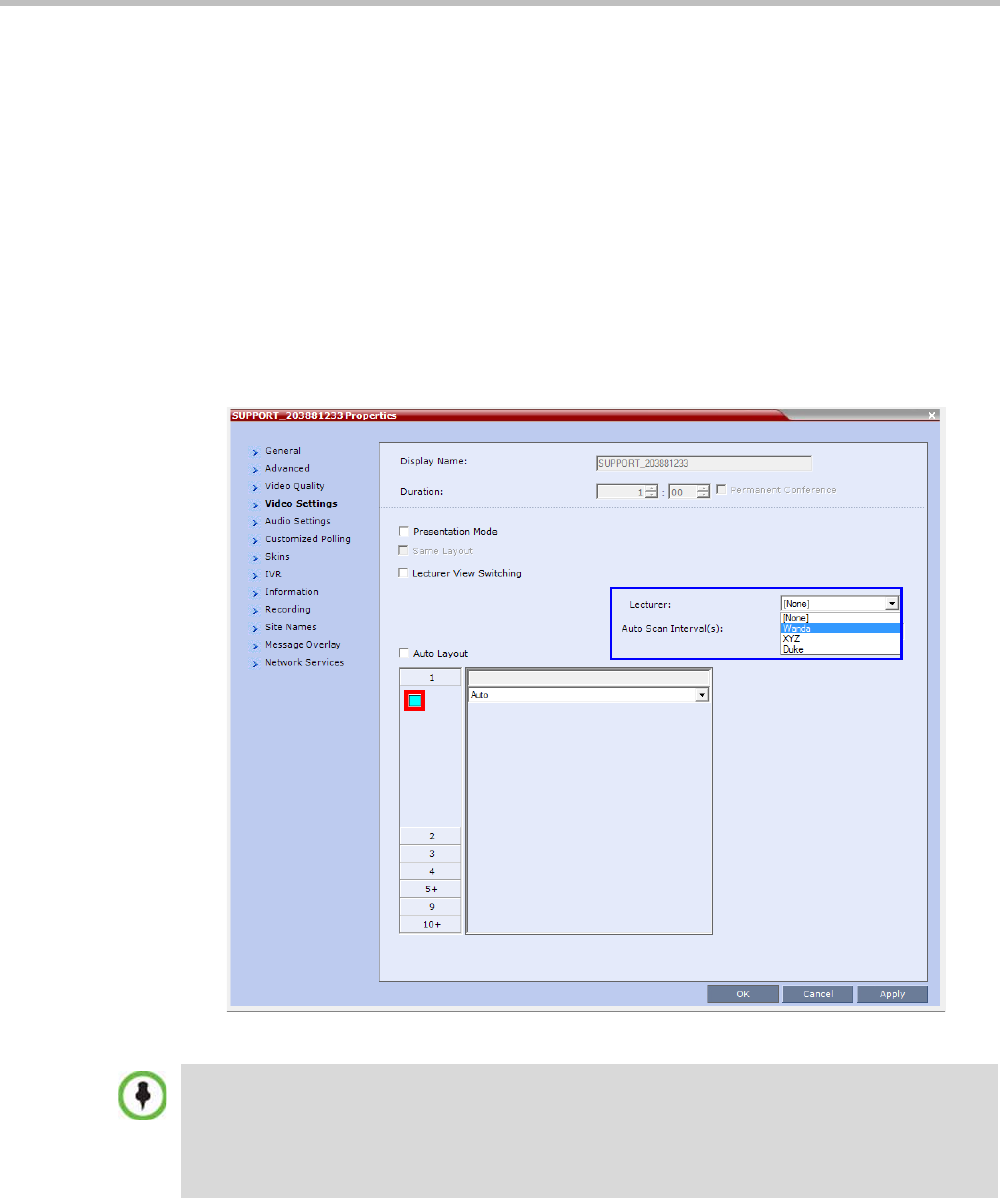
Chapter 3-Additional Conferencing Information
Polycom, Inc. 3-39
Selecting a defined participant:
aAdd participants to the conference either from the Address book or by defining
new participants.
bIn the Lecturer field, select the lecturer from the list of the defined participants.
Automatic selection of the lecturer:
—In the Lecturer field, select [Auto].
In this mode, the conference speaker becomes the lecturer.
To select the lecturer and enable the Lecture Mode during the ongoing conference:
1Make sure that the participant you want to designate as the lecturer has connected to
the conference.
2In the Conference Properties - Video Settings dialog box, in the Lecturer field, select the
lecturer from the list of the connected participants.
Defined dial out participants and dial in participants are considered to be two separate participants
even if they have the same IP address/number. Therefore, if a defined dial-out participant is added to
the conference and the same participant then dials in (before the system dialed out to that
participant) the system creates a second participant in the Participants list and tries to call the dial-
out participant. If the dial-out participant was designated as the conference lecturer, the system will
not be able to replace that participant with the dial-in participant that is connected to the conference.
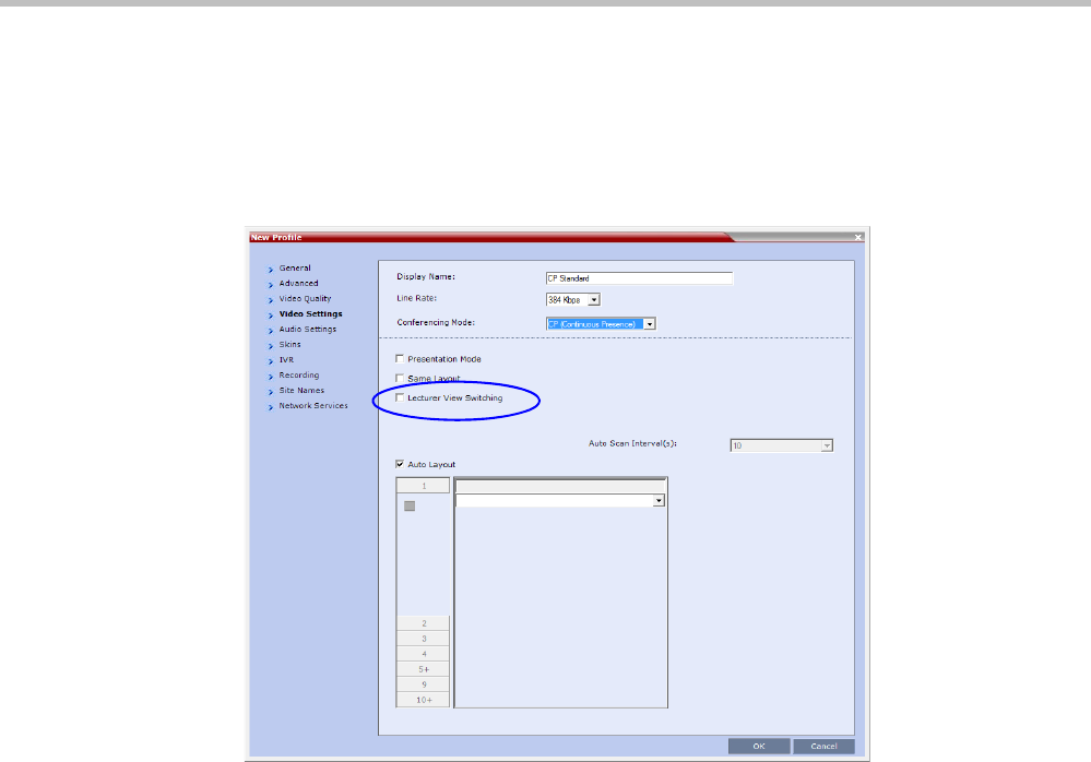
Polycom® RealPresence Collaboration ServerVirtual Edition Administrator’s Guide
3-40 Polycom, Inc.
Enabling the Automatic Switching
Automatic switching between participants viewed on the lecturer’s screen is enabled in the
conference Profile, or during the ongoing conference, in the Conference Properties.
>> In the Profile Properties - Video Settings dialog box, select the Lecturer View Switching
check box.
This option is activated when the conference includes more sites than windows in the
selected layout. If this option is disabled, the participants will be displayed in the
selected video layout without switching.
For more information about Profile definition, see "Defining AVC CP Conferencing
Profiles” on page 2-21.
>> Once the conference is running, in the Conference Properties - Video Settings dialog box,
select the Lecturer View Switching check box.
Lecture Mode Monitoring
A conference in which the Lecture Mode is enabled is started as any other conference. The
conference runs as an audio activated Continuous Presence conference until the lecturer
connects to the conference. The selected video layout is the one that is activated when the
conference starts. Once the lecturer is connected, the conference switches to the Lecture
Mode.
When Lecturer View Switching is activated, it enables automatic switching between the
conference participants in the lecturer’s video window. The switching in this mode is not
determined by voice activation and is initiated when the number of participants exceeds the
number of windows in the selected video layout. In this case, when the switching is
performed, the system refreshes the display and replaces the last active speaker with the
current speaker.
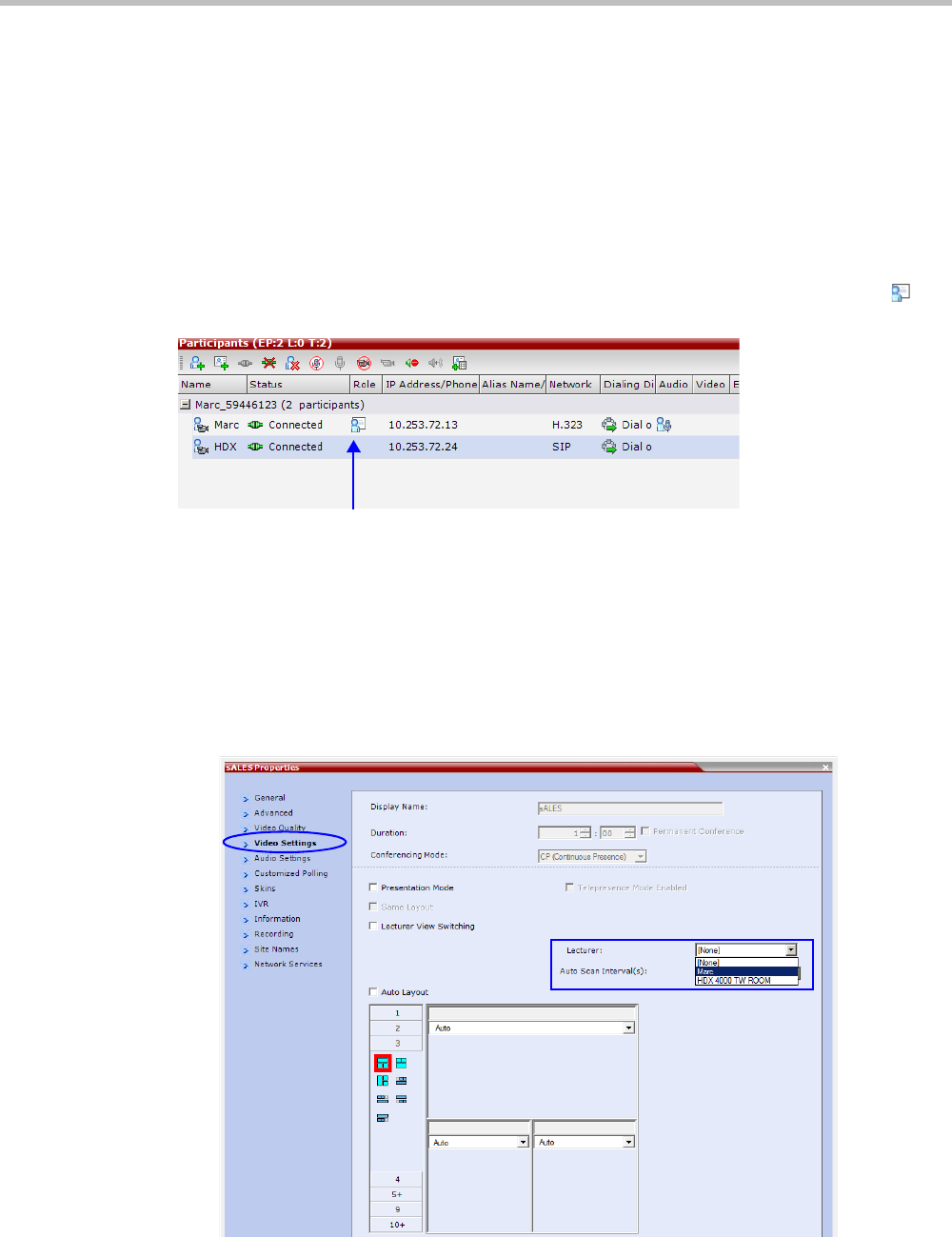
Chapter 3-Additional Conferencing Information
Polycom, Inc. 3-41
When one of the participants is talking, the automatic switching is suspended, showing the
current speaker, and it is resumed when the lecturer resumes talking.
If the lecturer is disconnected during an Ongoing Conference, the conference resumes
standard conferencing.
Forcing is enabled at the Conference level only. It applies only to the video layout viewed by
the lecturer as all the other conference participants see only the lecturer in full screen.
If an asymmetrical video layout is selected for the lecturer (i.e. 3+1, 4+1, 8+1), each video
window contains a different participant (i.e. one cannot be forced to a large frame and to a
small frame simultaneously).
When Lecture Mode is enabled for the conference, the lecturer is indicated by an icon ( ) in
the Role column of the Participants list.
To control the Lecture Mode during an Ongoing Conference:
During the Ongoing Conference, in the Conference Properties - Video Settings dialog box you
can:
• Enable or disable the Lecture Mode and designate the conference lecturer in the Lecturer
list; select None to disable the Lecture Mode or select a participant to become the
lecturer to enable it.
• Designate a new lecturer.
Participant designated as the
Lecturer
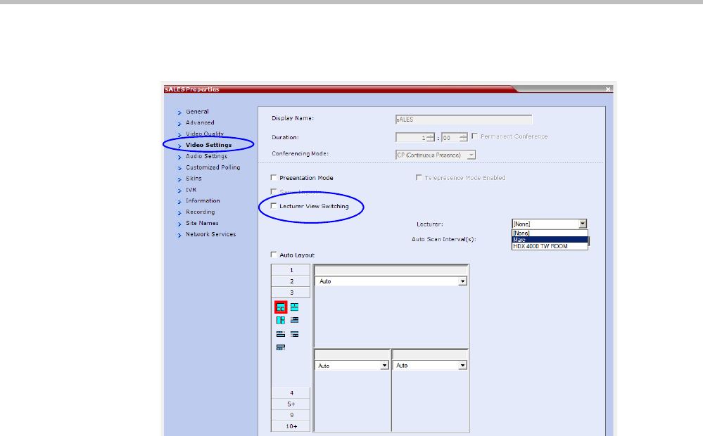
Polycom® RealPresence Collaboration ServerVirtual Edition Administrator’s Guide
3-42 Polycom, Inc.
• Enable or disable the Lecturer View Switching between participants displayed on the
lecturer monitor by selecting or clearing the Lecturer View Switching check box.
• Change the video layout for the lecturer by selecting another video layout.
Restricting Content Broadcast to Lecturer
Content broadcasting can be restricted to the conference lecturer only, when one of the
conference participants is set as the lecturer (and not automatically selected by the system).
Restricting the Content Broadcast prevents the accidental interruption or termination of
H.239 Content that is being shared in a conference.
Content Broadcast restriction is enabled by setting the
RESTRICT_CONTENT_BROADCAST_TO_LECTURER system flag to ON. When set to
OFF (default) it enables all users to send Content.
When enabled, the following rules apply:
• Content can only be sent by the designated lecturer. When any other participant tries to
send Content, the request is rejected.
• If the Collaboration Server user changes the designated lecturer (in the Conference
Properties - Video Settings dialog box), the Content of the current lecturer is stopped
immediately and cannot be renewed.
• The Collaboration Server User can abort the H.239 Session of the lecturer.
• Content Broadcasting is not implemented in conferences that do not include a
designated lecturer and the lecturer is automatically selected by the system (for
example, in Presentation Mode).

Chapter 3-Additional Conferencing Information
Polycom, Inc. 3-43
Muting Participants Except the Lecturer (AVC CP Only)
When the Mute Participants Except Lecturer option in the Conference Profile is enabled, the
audio of all participants in the conference except for the lecturer can be automatically muted
upon connection to the conference. This prevents other conference participants from
accidentally interrupting the lecture, or from a noisy participant affecting the audio quality
of the entire conference. Muted participants cannot unmute themselves unless they are
unmuted from the Collaboration Server Web Client/RMX Manager.
Guidelines
• Both administrators and operators (users) are allowed to set the Mute Participants Except
Lecturer option.
• When the Mute Participants Except Lecturer option is enabled, the mute indicator on the
participant endpoints are not visible because the mute participants was initiated by the
MCU. Therefore, it is recommended to inform the participants that their audio is muted
by using the Closed Caption or Message Overlay functions.
• When the Mute Participants Except Lecturer option is enabled in the Conference Profile
settings, all conferences to which this profile is assigned will start with this option
enabled. All participants, except for the designated lecturer, are muted.
•The Mute Participants Except Lecturer option can be enabled or disabled at any time after
the start of the conference. When enabled, it allows all the conference participants to
converse before the lecturer joins the conference or before they are muted. When
disabled, it unmutes all the participants in the conference.
• If the endpoint of the designated lecturer is muted when the lecturer connects to the
conference, the lecturer remains muted until the endpoint has been unmuted.
• When you replace a lecturer, the MCU automatically mutes the previous lecturer and
unmutes the new lecturer.
• When you disconnect a lecturer from the conference or the lecturer leaves the
conference, all participants remain muted but are able to view participants in regular
video layout until the you disable the Mute Participants Except Lecturer option.
• A participant can override the Mute Participants Except Lecturer option by activating the
Mute All Except Me option using the appropriate DTMF code, provided the participant
has authorization for this operation in the IVR Services properties. The lecturer audio is
muted and the participant audio is unmuted. You can reactivate the Mute Participants
Except Lecturer option after a participant has previously activated the Mute All Except
Me option. The participant is muted and the lecturer, if designated, is unmuted.
• In cascaded conferences, all participants (including the link participants) except the
lecturer are muted. Only the lecturer is not muted.
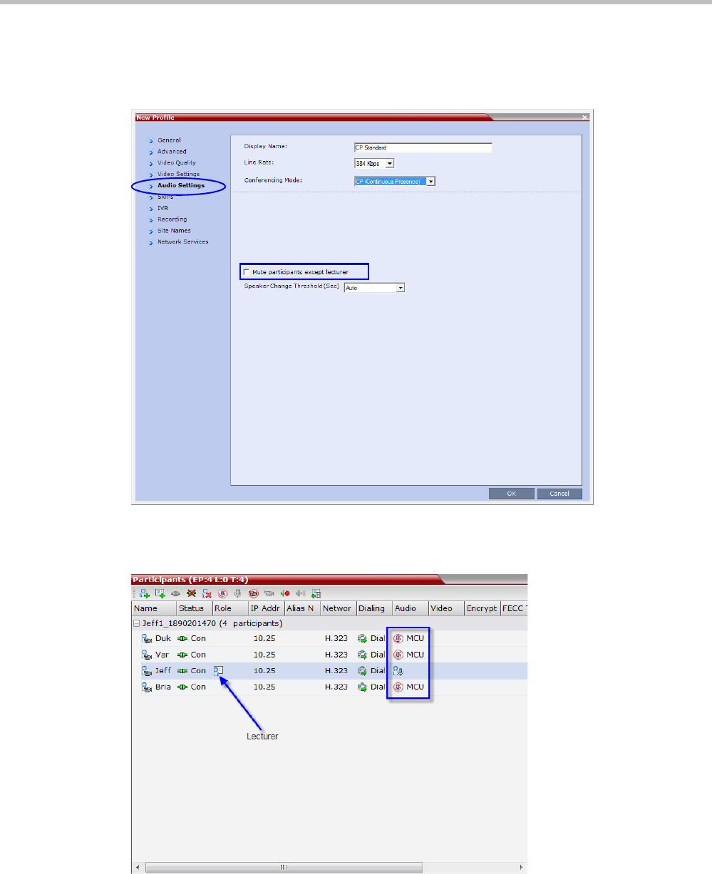
Polycom® RealPresence Collaboration ServerVirtual Edition Administrator’s Guide
3-44 Polycom, Inc.
Enabling the Mute Participants Except Lecturer Option
The Mute Participants Except Lecturer option is enabled or disabled (default) in the Conference
Profile or in an ongoing conference in the Profile Properties - Audio Settings tab.
When the Mute Participants Except Lecturer option is enabled and a conference has started,
the Mute by MCU icon is displayed in the Audio column in the Participants pane of each
participant that is muted.

Chapter 3-Additional Conferencing Information
Polycom, Inc. 3-45
Audio Algorithm Support
The Collaboration Server supports the following audio algorithms in AVC conferences:
G.711, G. 719, G.722, G.722.1, G.722.1C, G.729A, G.723.1, Polycom Siren 7 (in mono), Siren14,
Siren 22 (in mono or stereo) and SirenLPR.
Polycom’s proprietary Siren 22 and industry standard G.719 audio algorithms are supported
for participants connecting with Polycom endpoints.
The Siren 22 audio algorithm provides CD-quality audio for better clarity and less listener
fatigue with audio and visual communication applications. Siren 22 requires less computing
power and has much lower latency than alternative wideband audio technologies.
The SirenLPR audio algorithm provides CD-quality audio for better clarity and less listener
fatigue with audio and visual communication applications.
In SVC conferences, the system supports SAC (Scalable Audio Coding) audio algorithm.
Guidelines
•Siren 22 and G.719 are supported in both mono and stereo.
• Stereo is supported in H.323 calls only.
•Siren 22 is supported by Polycom HDX endpoints, version 2.0 and later.
•G.728 is supported in H.323 and SIP environments.
•SirenLPR is enabled by default and can be disabled by setting the system flag,
ENABLE_SIRENLPR, to NO.
•SirenLPR is supported:
—In IP (H.323, SIP) calls only.
—In CP and VSW conferences.
—With Polycom CMAD and HDX “Canyon 3.0.1” endpoints.
—For mono audio at audio line rates of 32Kbps, 48Kbps and 64Kbps.
—For stereo audio at audio line rates of 64Kbps, 96Kbps and 128Kbps.
SIP Encryption
The ENABLE_SIRENLPR_SIP_ENCRYPTION System Flag enables the SirenLPR audio
algorithm when using encryption with the SIP protocol.
The default value of this flag is NO meaning SirenLPR is disabled by default for SIP
participants in an encrypted conference. To enable SirenLPR the System Flag must be added
to system.cfg and its value set to YES.
Mono
The Siren 22, G.719 and SirenLPR mono audio algorithms are supported at the following bit
rates:
Table 3-12 Siren22, G.719 and SirenLPR Mono vs Bitrate
Audio Algorithm Minimum Bitrate (kbps)
Siren22 64k
Siren22 48K
Siren22_32k

Polycom® RealPresence Collaboration ServerVirtual Edition Administrator’s Guide
3-46 Polycom, Inc.
Stereo
The Siren 22Stereo, G.719Stereo and SirenLPR audio algorithms are supported at the
following bit rates.
G.719_64k 384
G.719_48k
G.719_32k
G.728 16K
G.719_64k 384
SirenLPR_48k 256
Siren22_48K
G.719_48k
G.7221C_48k
Siren14_48k
SirenLPR_32k
128
Siren22_32k
G.719_32k
G.7221C_32k
Siren14_32k
SirenLPR 64
SirenLPR 48
SirenLPR 32
Table 3-13 Siren22Stereo, G.719Stereo and SirenLPR vs Bitrate
Audio Algorithm Minimum Bitrate (kbps)
Siren22Stereo_128k
1024SirenLPRStereo_128k
G.719Stereo_128k
Siren22Stereo_96k
512
SirenLPRStereo_96k
G.719Stero_96k
Siren14Stero_96k
Table 3-12 Siren22, G.719 and SirenLPR Mono vs Bitrate (Continued)
Audio Algorithm Minimum Bitrate (kbps)
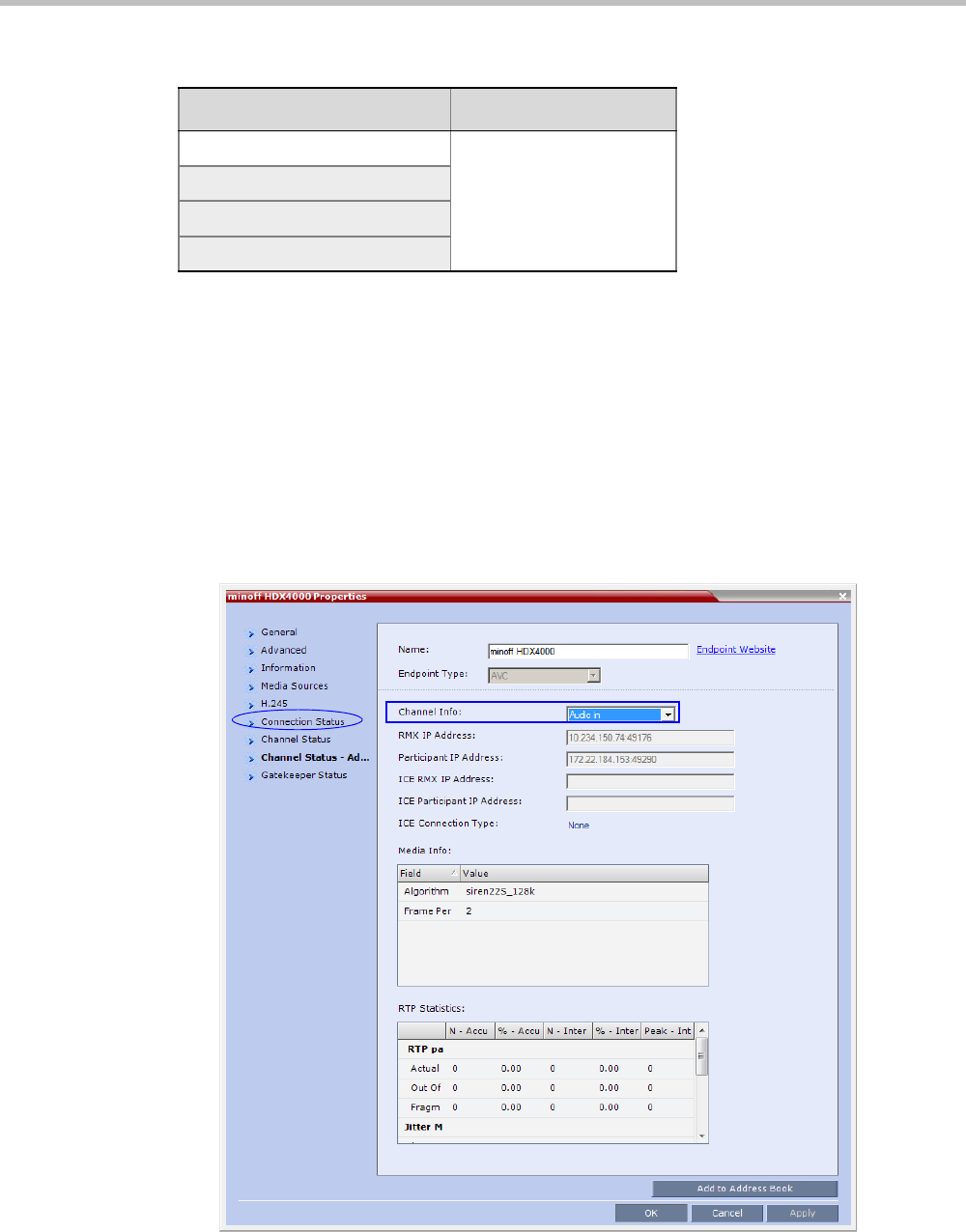
Chapter 3-Additional Conferencing Information
Polycom, Inc. 3-47
Monitoring Participant Audio Properties
The audio algorithm used by the participant’s endpoint can be verified in the Participant
Properties - Channel Status dialog box.
To view the participant’s properties during a conference:
1In the Participants list, right click the desired participant and select Participant
Properties.
2Click the Channel Status - Advanced tab.
The Participant Properties - Channel Status - Advanced dialog box is displayed.
3In the Channel Info field, select Audio In or Audio Out to display the audio parameters.
4Click the OK button.
SirenLPRStereo_64k
384
G.719Stereo_64k
Siren22Stereo_64k
Siren14Stereo_64k
Table 3-13 Siren22Stereo, G.719Stereo and SirenLPR vs Bitrate (Continued)
Audio Algorithm Minimum Bitrate (kbps)

Polycom® RealPresence Collaboration ServerVirtual Edition Administrator’s Guide
3-48 Polycom, Inc.
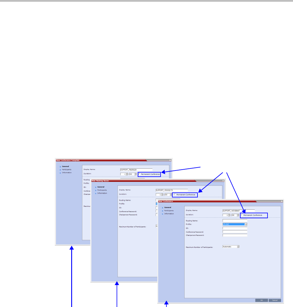
Chapter 3-Additional Conferencing Information
Polycom, Inc. 3-49
Permanent Conference
A Permanent Conference is any ongoing conference with no pre-determined End Time
continuing until it is terminated by an administrator, operator or chairperson.
Guidelines
•Auto Terminate is disabled in Permanent Conferences.
• If participants disconnect from the Permanent Conference, resources are released.
•Entry Queues, Conference Reservations and SIP Factories cannot be defined as Permanent
Conferences.
• Additional participants can connect to the conference, or be added by the operator, if
sufficient resources are available.
• The maximum size of the Call Detail Record (CDR) for a Permanent Conference is 1MB.
Enabling a Permanent Conference
The Permanent Conference option is selected in the New Conference, New Meeting Room or New
Conference Templates dialog boxes.
New Conference New Meeting Room New Conference Template
Permanent Conference

Polycom® RealPresence Collaboration ServerVirtual Edition Administrator’s Guide
3-50 Polycom, Inc.

Polycom, Inc. 4-1
4
Video Protocols and Resolution
Configuration for CP Conferencing
Video Resolutions in AVC-based CP Conferencing
The Polycom® RealPresence® Collaboration Server always attempts to connect to endpoints
at the highest line rate defined for the conference. If the connection cannot be established
using the conference line rate, the Collaboration Server attempts to connect at the next
highest line rate at its highest supported resolution.
Depending on the line rate, the Collaboration Server sends video at the best possible
resolution supported by the endpoint regardless of the resolution received from the
endpoint.
The video resolution is also defined by the Video Quality settings in the Profile.
The combination of frame rate and resolution affects the number of video resources
required on the MCU to support the call.
The following resolutions are supported:
• CIF 352 x 288 pixels.
• SD 720 x 576 pixels.
• HD 720p 1280 x 720 pixels.
Video Display with CIF, SD and HD Video Connections
Although any combination of CIF, SD and HD connections is supported in all CP
conferences, the following rules apply:
• In a 1X1 Video Layout:
—SD: If the speaker transmits CIF, the MCU will send CIF to all participants,
including the SD participants. In any other layout the MCU will transmit to each
participant at the participant’s sending resolution.
—HD: The MCU transmits speaker resolution (including input from HD
participants) at up to SD resolution. If 1x1 is the requested layout for the entire
duration of the conference, set the conference to HD Video Switching mode.
• In asymmetrical Video Layouts:
—SD: A participant in the large frame that sends CIF is displayed in CIF.
—HD: Where participants’ video windows are different sizes, the Collaboration Server
transmits HD and receives SD or lower resolutions.
The following video resolution information applies to AVC Conferencing Mode.
For a description of resolutions for SVC Conferencing Mode see “SVC-based Conferencing”.
RealPresence Collaboration Server Virtual Edition Administrator’s Guide
4-2 Polycom, Inc.
• In panoramic Video Layouts:
—SD: Participants that send CIF also receive CIF.
—HD: the Collaboration Server transmits HD and receives SD or lower resolutions,
the Collaboration Server scales images from SD to HD resolution.
H.264 High Profile Support in CP Conferences
The H.264 High Profile is a new addition to the H.264 video protocol suite. It uses the most
efficient video data compression algorithms to even further reduce bandwidth requirements
for video data streams.
Video quality is maintained at bit rates that are up to 50% lower than previously required.
For example, a 512Kbps call will have the video quality of a 1Mbps HD call while a 1Mbps
HD call has higher video quality at the same (1Mbps) bit rate.
Guidelines
•H.264 High Profile is supported in H.323 and SIP networking environments.
•H.264 High Profile is supported in Continuous Presence conferences at all bit rates, video
resolutions and layouts.
•H.264 High Profile is the first protocol declared by the Collaboration Server, to ensure
that endpoints that support the protocol will connect using it.
Setting minimum bit rate thresholds that are lower than the default may affect the video
quality of endpoints that do not support the H.264 High Profile.
• For monitoring purposes, the Collaboration Server and endpoint H.264 High Profile
capability is listed in the Participant Properties - H.245 and SDP tabs for H.323
participants and SIP participants respectively.
For more information see "IP Participant Properties” on page 12-20.
•H.264 High Profile is not supported:
—For Content Sharing
—As an RSS Recording link
—With Video Preview
CP Conferencing with H.263 4CIF
The video resolution of 4CIF in H.263 endpoints is only supported for line rates of 384 Kbps
to 1920 Kbps as shown in Table 4-1.
H.264 High-Profile should be used when all or most endpoints support it.
Table 4-1 Video Quality vs. Line Rate
Endpoint Line Rate Kbps
Video Quality
Resolution Frame Rate
128 CIF 30
256 CIF 30

Chapter 4-Video Protocols and Resolution Configuration for CP Conferencing
Polycom, Inc. 4-3
The Collaboration Server Web Client supports monitoring of H.263 4CIF information. The
H.245 or SDP tab includes the additional information.
The creation of a new H.263 4CIF slide is supported in the IVR Service in addition to the
current H.263 IVR slide. If users utilize the default Polycom slides that are delivered with
the RealPresence Collaboration Server, the slide’s resolution will be as defined in the profile,
i.e. SD, HD, CIF, etc.
For more information see “High Resolution Slides” on page 16-14.
H.263 4CIF Guidelines
• H.263 4CIF is supported with H.323 and SIP connection endpoints.
• H.263 4CIF is supported in CP mode only.
• Click & View is supported in H.263 4CIF.
• AES encryption is supported with H.263 4CIF.
• H.263 4CIF is supported in recording by the RSS2000 and other recording devices.
• All video layouts are supported in H.263 4CIF, except 1x1 layout. In a 1x1 layout, the
resolution will be CIF.
• For information about Resource Usage see Table 19-7 on page 19-8.
• H.239 is supported in H.263 4CIF and is based on the same bandwidth decision matrix
as for HD.
The CP Resolution Decision Matrix
All the CP resolution options and settings are based on a decision matrix which matches
video resolutions to connection line rates, with the aim of providing the best balance
between resource usage and video quality at any given line rate.
The following factors affect the decision matrices:
• The video protocol used: H.264 base Profile or H.264 High Profile. The H.264 High Profile
maintains the Video quality at bit rates that are up to 50% lower than previously
required. For example, a 512 kbps call will have the video quality of a 1Mbps HD call
while a 1Mbps HD call has higher video quality at the same (1Mbps) bit rate.
By default, the system shipped with three pre-defined settings of the decision matrix for
H.264 Base Profile and three pre-defined settings of the decision matrix for H.264 High Profile:
•Resource-Quality Balanced (default)
A balance between video quality and resource usage.
•Resource Optimized
System resource usage is optimized by allowing high resolution connections only at
high line rates and may result in lower video resolutions (in comparison to other
resolution configurations) for some line rates. This option allows to save MCU
resources and increase the number of participant connections.
384 - 1920+ 4CIF 15
Table 4-1 Video Quality vs. Line Rate (Continued)
Endpoint Line Rate Kbps
Video Quality
Resolution Frame Rate
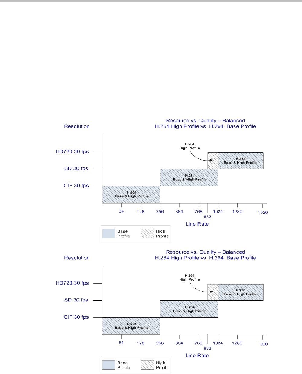
RealPresence Collaboration Server Virtual Edition Administrator’s Guide
4-4 Polycom, Inc.
•Video Quality Optimized
Video is optimized through higher resolution connections at lower line rates increasing
the resource usage at lower line rates. This may decrease the number of participant
connections.
Video Resource Usage
Video resource usage is dependent on the participant’s line rate, resolution and Video
Quality settings.
H.264 Base Profile and High Profile Comparison
The following illustrations show a comparison between the resolutions used at various line
rates for H.264 Baseline and the H.264 High Profile Video Quality setting.
Figure 4-1 Resolution usage for H.264 High Profile and H.264 Base Profile at various line rates
when Resolution Configuration is set to Resource-Quality Balanced
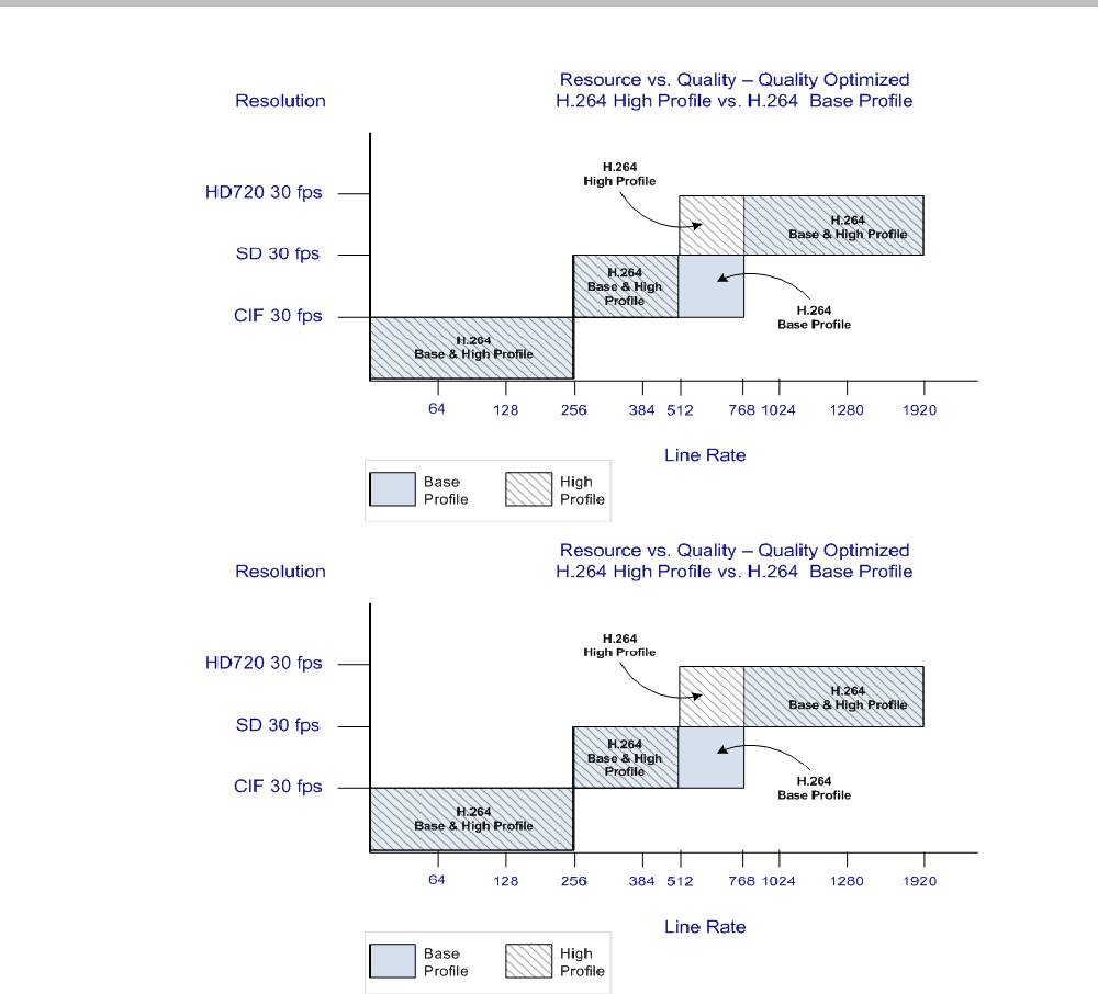
Chapter 4-Video Protocols and Resolution Configuration for CP Conferencing
Polycom, Inc. 4-5
Figure 4-2 Resolution usage for H.264 High Profile and H.264 Base Profile at various line rates
when Resolution Configuration is set to Video Quality Optimized
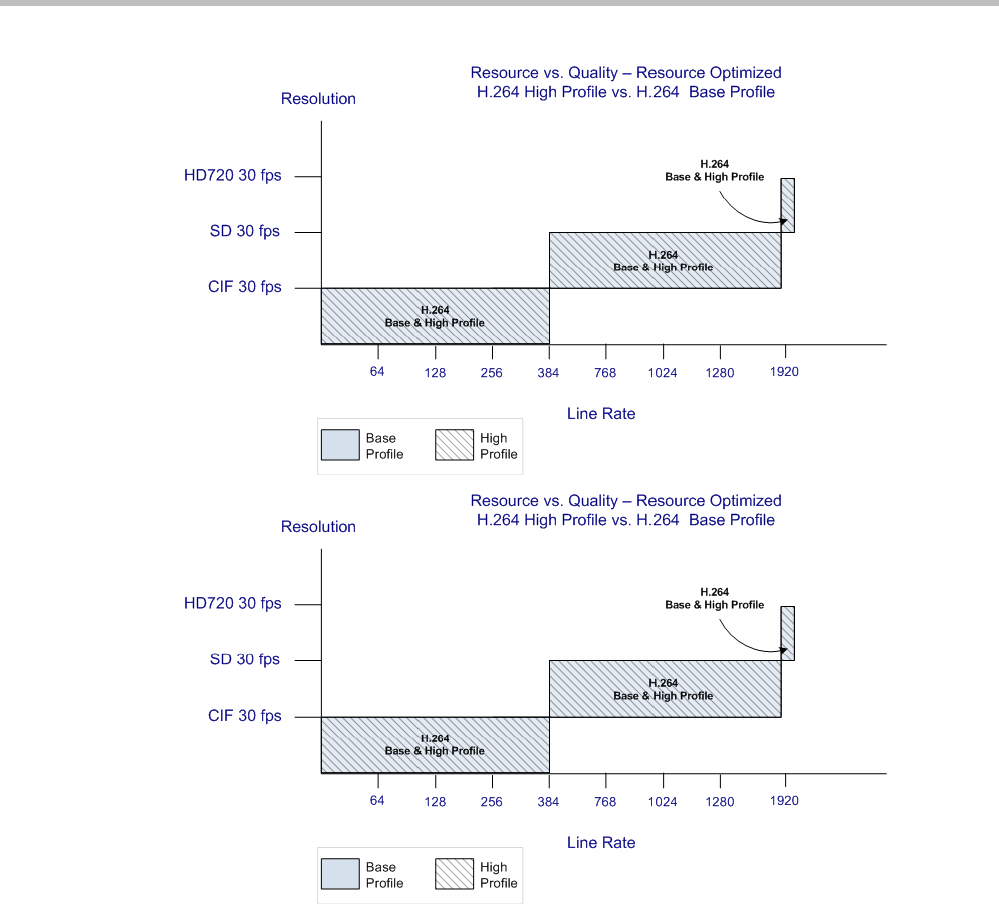
RealPresence Collaboration Server Virtual Edition Administrator’s Guide
4-6 Polycom, Inc.
Figure 4-3 Resolution usage for H.264 High Profile and H.264 Base Profile at various line rates
when Resolution Configuration is set to Resource Optimized
Default Minimum Threshold Line Rates and Resource Usage Summary
The following Table summarizes the Default Minimum Threshold Line Rates and Video
Resource usage for each of the pre-defined optimization settings for each Resolution, H.264
Profile, Video Quality setting.
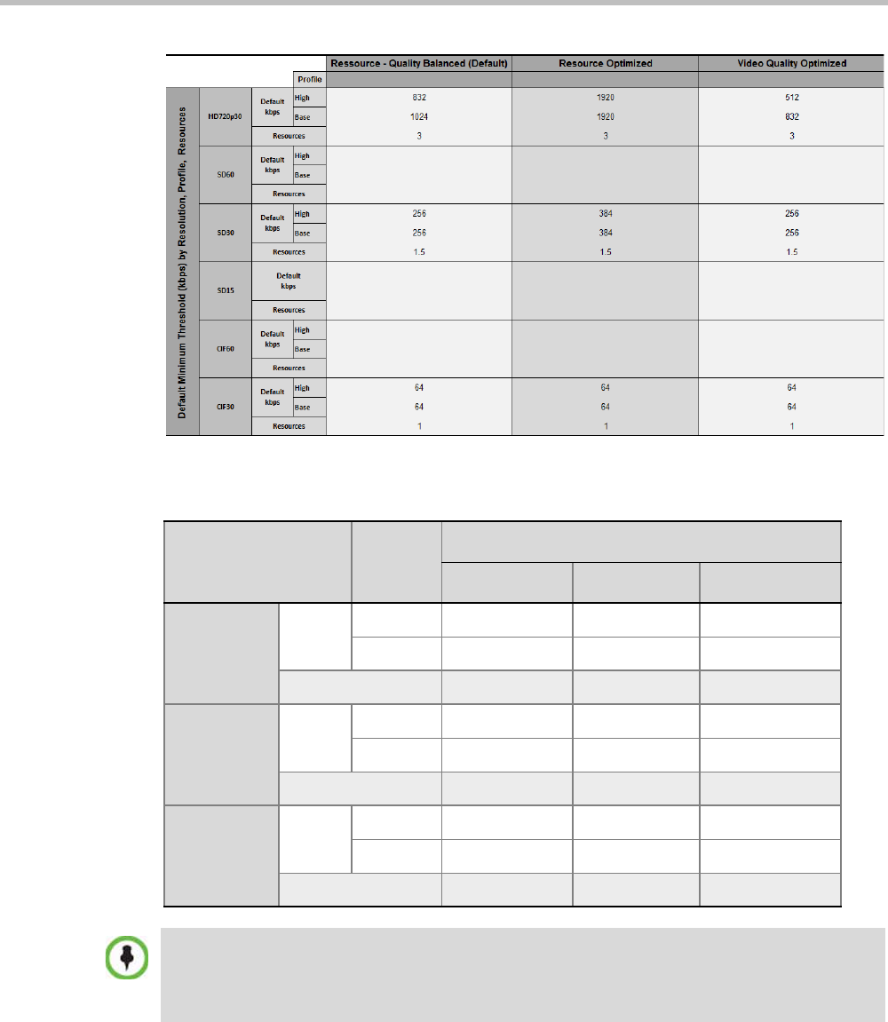
Chapter 4-Video Protocols and Resolution Configuration for CP Conferencing
Polycom, Inc. 4-7
Table 4-2 Default Minimum Threshold Line Rates and Video Resource Usage
Resolution
Profile
Optimization Mode
Balanced Resource Video Quality
HD720p30
Default
kbps
High 832 1920 512
Base 1024 1920 832
Resources 2 2 2
SD 30
Default
kbps
High 256 384 256
Base 256 384 256
Resources 1 1 1
CIF 30
Default
kbps
High 64 64 64
Base 64 64 64
Resources 1 1 1
The table above lists resource consumption for H.264:
•CIF resolution consumes 1 resources.
•4CIF resolution consumes 1 resources.
•HD720p resolution consumes 2 resources.

RealPresence Collaboration Server Virtual Edition Administrator’s Guide
4-8 Polycom, Inc.
Resolution Configuration for CP Conferences
The Resolution Configuration dialog box enables Collaboration Server administrators to
override the default video resolution decision matrix, effectively creating their own decision
matrix. The minimum threshold line rates at which endpoints are connected at the various
video resolutions can be optimized by adjusting the resolution sliders.
System resource usage is also affected by the Resolution Configuration settings. For more
information see "Video Resource Usage” on page 4-4 and "Default Minimum Threshold Line
Rates and Resource Usage Summary” on page 4-6.
Guidelines
•Resolution Slider settings affect all Continuous Presence (CP) conferences running on the
Collaboration Server. Video Switched conferences are not affected.
• A system restart is not needed after changing the Resolution Slider settings.
•Resolution Slider settings cannot be changed if there are ongoing conferences running on
the Collaboration Server.
Modifying the Resolution Configuration
The Resolution Configuration dialog box is accessed by clicking Setup > Resolution
Configuration in the Collaboration Server Setup menu.
Clicking the Detailed Configuration button toggles the display of the Detailed Configuration
pane, which displays sliders for modifying minimum connection threshold line rates for
endpoints that support H.264 Base Profile or High Profile.
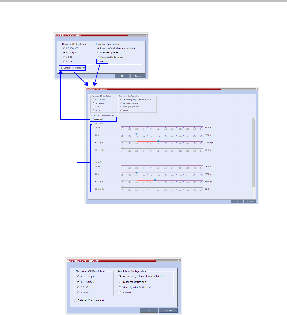
Chapter 4-Video Protocols and Resolution Configuration for CP Conferencing
Polycom, Inc. 4-9
The Detailed Configuration pane can also be opened by clicking the Manual radio button in
the Resolution Configuration pane.
Resolution Configuration - Basic
The Resolution Configuration -Basic dialog box contains the following panes:
•Max CP Resolution Pane
•Resolution Configuration Pane
Maximum CP Resolution Pane
The Collaboration Server can be set to one of the following Maximum CP Resolutions:
• HD 720p30
•SD 30
•CIF 30
Basic Configuration
Minimum
Connection
Threshold
Line Rate
Sliders
Detailed Configuration
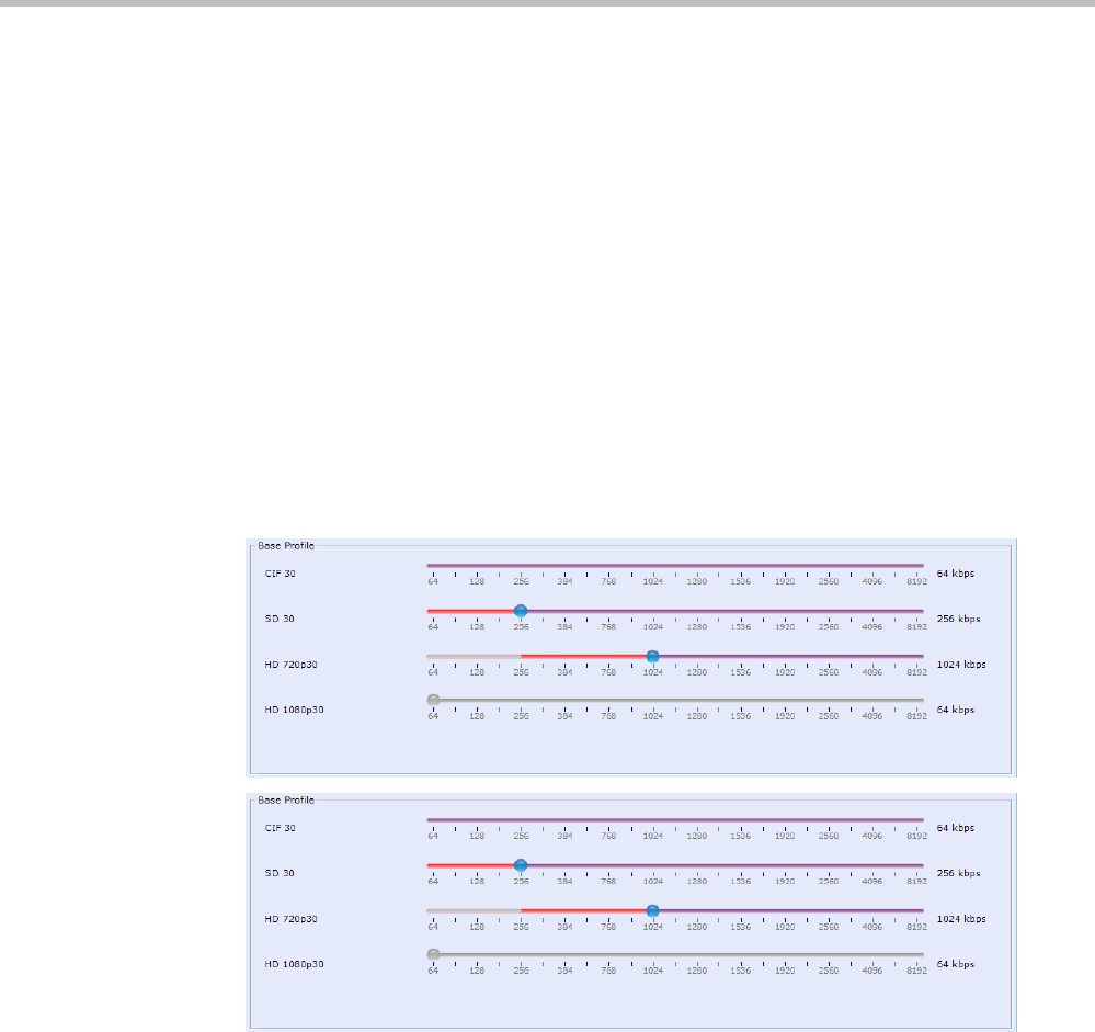
RealPresence Collaboration Server Virtual Edition Administrator’s Guide
4-10 Polycom, Inc.
Limiting Maximum Resolution
Before a selection is made in this pane, the Maximum CP Resolution of the system is
determined by the MAX_CP_RESOLUTION System Flag.
Resolution Configuration - Detailed
H.264 High Profile allows higher quality video to be transmitted at lower bit rates.
However, setting minimum bit rate thresholds that are lower than the default may affect the
video quality of endpoints that do not support the H.264 High Profile. The Collaboration
Server uses two decision matrices (Base Profile, High Profile) to enable endpoints to connect
according to their capabilities.
Resolution Configuration Sliders
The Detailed Configuration dialog box allows the administrator to configure minimum
connection threshold bit rates for endpoints that support H.264 High Profile and those that
do not support H.264 High Profile by using the following slider panes:
• Base Profile - Endpoints that do not support H.264 High Profile connect at these
minimum threshold bit rates.
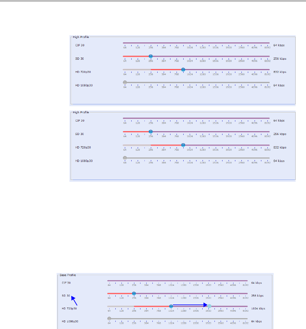
Chapter 4-Video Protocols and Resolution Configuration for CP Conferencing
Polycom, Inc. 4-11
•High Profile - Endpoints that support H.264 High Profile connect at these minimum
threshold bit rates.
Although the default minimum threshold bit rates provide acceptable video quality, the
use of higher bit rates usually results in better video quality.
These Video Quality settings are selected per conference and are defined in the conference
Profile and they determine the resolution matrix that will be applied globally to all
conferences. The resolution matrix is determined by the resolution configuration and can be
viewed in the Resolution Configuration sliders.
System Resource usage is affected by the Resolution Configuration settings.
Example
As shown in following diagram:
•Moving the HD720p30 resolution slider from 1024kbps to 1920kbps increases the
minimum connection threshold line rate for that resolution. Endpoints connecting at
line rates between 1024kbps and 1920kbps that would have connected at HD 720p30
resolution will instead connect at SD 30 resolution. Each of the affected endpoints will
connect at lower resolution but will use 1 system resource instead of 2 system resources.

RealPresence Collaboration Server Virtual Edition Administrator’s Guide
4-12 Polycom, Inc.
Flag Settings
Setting the Maximum CP Resolution for Conferencing
The MAX_CP_RESOLUTION flag value is applied to the system during First-time Power-up
and after a system upgrade. The default value is HD720p30.
All subsequent changes to the Maximum CP Resolution of the system are made by selections
in the Max Resolution pane of the Resolution Configuration dialog box.
The Collaboration Server can be set to one of the following resolutions:
•HD720p30
•SD 30
•CIF 30
Minimum Frame Rate Threshold for SD Resolution
The MINIMUM_FRAME_RATE_THRESHOLD_FOR_SD System Flag can be added and
set to prevent low quality, low frame rate video from being sent to endpoints by ensuring
that an SD channel is not opened at frame rates below the specified value. For more
information see "Modifying System Flags” on page 20-1.

Chapter 4-Video Protocols and Resolution Configuration for CP Conferencing
Polycom, Inc. 4-13
Additional Video Resolutions
The following higher video quality resolutions are available:
• CIF 352 x 288 pixels at 50 fps.
• WCIF 512 x 288 pixels at 50 fps.
• WSD 848 x 480 pixels at 50 fps.
• W4CIF 1024 x 576 pixels at 30 fps.
• HD 720p 1280 x 720 pixels at 30fps
Additional Intermediate Video Resolutions
Two higher quality, intermediate video resolutions replace the transmission of CIF (352 x
288 pixels) or SIF (352 x 240 pixels) resolutions to endpoints that have capabilities between:
•CIF (352 x 288 pixels) and 4CIF (704 x 576 pixels) – the resolution transmitted to these
endpoints is 432 x 336 pixels.
•SIF (352 x 240 pixels) and 4SIF (704 x 480 pixels) – the resolution transmitted to these
endpoints is 480 x 352 pixels.
• The frame rates (depending on the endpoint’s capability) for both intermediate
resolutions are 25 or 30 fps.
Microsoft RTV Video Protocol Support in CP Conferences
Microsoft RTV (Real Time Video) protocol provides high quality video conferencing capability
to Microsoft OC (Office Communicator) Client endpoints at resolutions up to HD720p30.
Interoperability between Polycom HDX and OCS endpoints is improved.
Guidelines
•The RTV protocol is supported:
—In SIP networking environments only
—In CP mode only
•OCS (Wave 13) and Lync Server (Wave 14) clients are supported.
•RTV is supported in Basic Cascade mode.
•RTV is the default protocol for OCS endpoints and Lync Server clients connecting to a
conference.
•RTV participants are supported in recorded conferences.
•RTV participant encryption is supported using the SRTP protocol.
•Video Preview is not supported for RTV endpoints.
•Custom Slides in IVR Services are not supported for RTV endpoints.
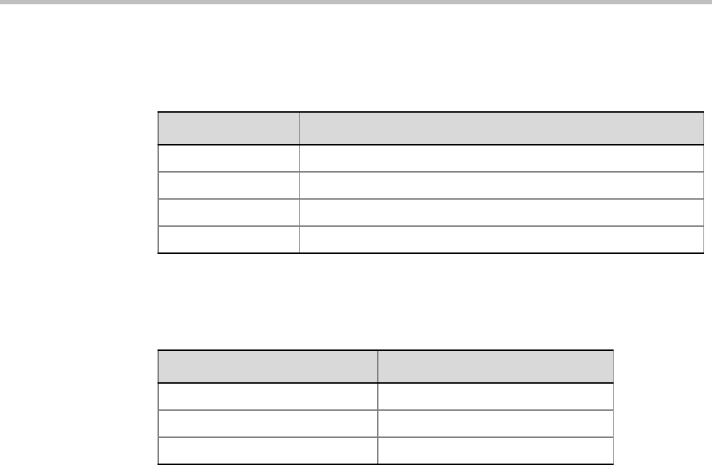
RealPresence Collaboration Server Virtual Edition Administrator’s Guide
4-14 Polycom, Inc.
•HD720p30 resolution is supported at bit rates greater than 600 kbps. The following table
summarizes the resolutions supported at the various bit rates.
* Dependant on the PC’s capability
•System Resource usage is the same as for the H.264 protocol. Table 4-4 summarizes
System Resource usage for each of the supported resolutions.
Table 4-3 RTV - Resolution by Bit Rate
Resolution Bitrate
QCIF Bitrate <180kbps
CIF30 180kbps < Bitrate < 250kbps
VGA (SD30) 250kbps < Bitrate < 600kbps *
HD720p30 600kbps < Bitrate *
Table 4-4 RTV - Resources by Resolution
Resolution HD Video Resources Used
QCIF / CIF30 0.333
VGA (SD30) / W4CIF 0.5
HD720p30 1
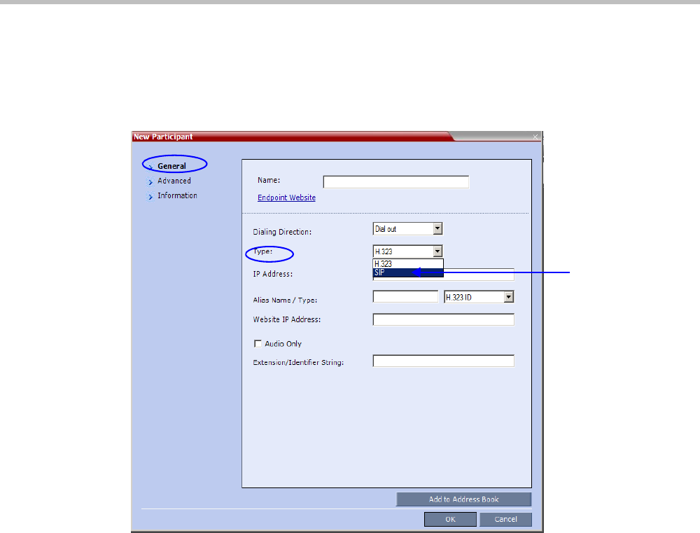
Chapter 4-Video Protocols and Resolution Configuration for CP Conferencing
Polycom, Inc. 4-15
Participant Settings
When defining a new participant or modifying an existing participant, select SIP as the
participant’s networking environment Type in the
New Participant
or
Participant Properties -
General tab.
The participants Video Protocol in the
New Participant
or
Participant Properties -
Advanced tab
should be left at (or set to) its default value: Auto.
The Auto setting allows the video protocol to be negotiated according to the endpoint’s
capabilities:
•OCS endpoints and Lync Server clients connect to the conference using the RTV
protocol.
• Other endpoints negotiate the video protocol in the following sequence: H.264,
followed by RTV, followed by H.263 and finally H.261.
Protocol Forcing
Selecting H.264, RTV, H.263 or H.261 as the Video Protocol results in endpoints that do not
support the selected Video Protocol connecting as Secondary (audio only).
SIP
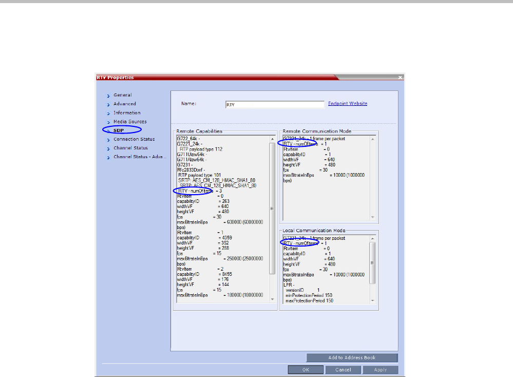
RealPresence Collaboration Server Virtual Edition Administrator’s Guide
4-16 Polycom, Inc.
Monitoring RTV
RTV information appears in all three panes of the Participant Properties - SDP tab.
Controlling Resource Allocations for Lync Clients Using RTV Video
Protocol
The number of resources used by the system to connect a Lync client with RTV is
determined according to the conference line rate and the Maximum video resolution set in
the Conference Profile.
The system flag MAX_RTV_RESOLUTION enables you to override the Collaboration
Server resolution selection and limit it to a lower resolution. Resource usage can then be
minimized the 1 or 1.5 video resources per call instead of 3 resources, depending on the
selected resolution.
Possible flag values are: AUTO (default), QCIF, CIF, VGA or HD720.
For example, if the flag is set to VGA, conference line rate is 1024Kbps, and the Profile
Maximum Resolution is set to Auto, the system will limit the Lync RTV client to a resolution
of VGA instead of HD720p and will consume only 1.5 video resources instead of 3
resources.
When set to AUTO (default), the system uses the default resolution matrix based on the
conference line rate.
To change the default flag setting, add the MAX_RTV_RESOLUTION flag to the System
Configuration flags and set its value. For information, see .

Chapter 4-Video Protocols and Resolution Configuration for CP Conferencing
Polycom, Inc. 4-17
The following table summarizes the Collaboration Server resources allocated to a Lync
Client based on the MAX_RTV_RESOLUTION flag setting, the connection line rate and the
video resolution.
Table 4-5 Selected video resolution based on flag setting and conference line rate and core
processor
Maximum
Resolution
Value
Line Rate
Selected Video Resolution Per Core Processor
Quad Dual Single
AUTO > 600 kbps HD720p 30fps VGA 30fps VGA 15fps
250 kbps - 600 kbps VGA 30fps VGA 30fps VGA 15fps
180 kbps - 249 kbps CIF CIF CIF
64 kbps - 179 kbps QCIF QCIF QCIF
HD720p > 600 kbps HD720p 30fps HD720p 13fps VGA 15fps
250 kbps - 600 kbps VGA 30fps VGA 30fps VGA 15fps
180 kbps - 249 kbps CIF CIF CIF
64 kbps - 179 kbps QCIF QCIF QCIF
VGA > 600 kbps VGA 30fps VGA 30fps VGA 15fps
250 kbps - 600 kbps VGA 30fps VGA 30fps VGA 15fps
180 kbps - 249 kbps CIF CIF CIF
64 kbps - 179 kbps QCIF QCIF QCIF
CIF > 600 kbps CIF CIF CIF
250 kbps - 600 kbps CIF CIF CIF
180 kbps - 249 kbps CIF CIF CIF
64 kbps - 179 kbps QCIF QCIF QCIF
QCIF > 600 kbps QCIF QCIF QCIF
250 kbps - 600 kbps QCIF QCIF QCIF
180 kbps - 249 kbps QCIF QCIF QCIF
64 kbps - 179 kbps QCIF QCIF QCIF
When the MAX_ALLOWED_RTV_HD_FRAME_RATE flag equals 0 (default value), Table 1-1 for the
MAX_RTV_RESOLUTION flag applies. When the MAX_ALLOWED_RTV_HD_FRAME_RATE flag
does not equal 0, see "Threshold HD Flag Settings using the RTV Video Protocol” on page 3-30 for
more information.
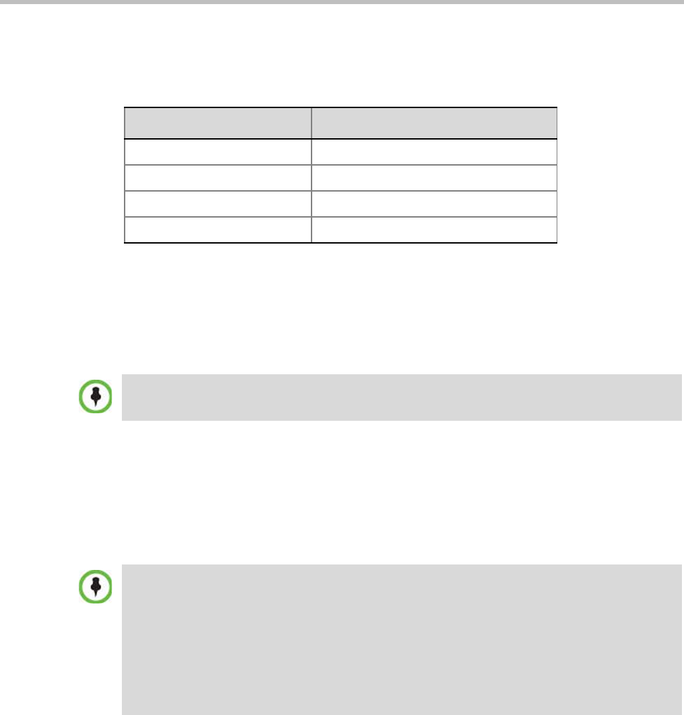
RealPresence Collaboration Server Virtual Edition Administrator’s Guide
4-18 Polycom, Inc.
The following table describes the number of allocated video resources for each video
resolution when using the RTV protocol.
Threshold HD Flag Settings using the RTV Video Protocol
The system flag MAX_ALLOWED_RTV_HD_FRAME_RATE defines the threshold Frame
Rate (fps) in which RTV Video Protocol initiates HD resolutions.
Flag values are as follows:
•Default: 0 (fps) - Implements any Frame Rate based on Lync RTV Client capabilities
•Range: 0-30 (fps)
For example, when the flag is set to 15 and the Lync RTV Client declares HD 720P at 10fps,
because the endpoint’s frame rate (fps) of 10 is less than flag setting of 15, then the
endpoint’s video will open VGA and not HD.
In another example, when the flag is set to a frame rate of 10 and the Lync RTV Client
declares HD 720P at 13fps, because the endpoint’s frame rate (fps) of 13 is greater than flag
setting of 10, then the endpoint’s video will open HD and not VGA.
Table 4-6 Allocated video resolutions per video resolution
Selected Video Resolution Number of Allocated Video Resources
HD720p 3
VGA 1.5
CIF 1
QCIF 1
If the MAX_RTV_RESOLUTION flag is set to AUTO dual core systems always view VGA. For more
information on Lync RTV Client capabilities, see , "Controlling Resource Allocations for Lync Clients
Using RTV Video Protocol” on page 3-23 for more information.
•Single core PC’s cannot view HD and always connect in VGA.
•Dual Core Processor - The threshold for flag settings on Dual Core systems is 13 (fps) and less
for viewing HD. When system flag is set to 14 (fps) or higher, the RTV Video Protocol shall
connect in VGA.
•Quad Core PC systems always view HD, even when flag settings are set anywhere from to 0-30.
•The number of resources used by the system to connect a Lync client with RTV is determined
according to the conference line rate and the maximum video resolution set in the Conference
Profile. For more information, see "Microsoft RTV Video Protocol Support in CP Conferences”
on page 3-20.
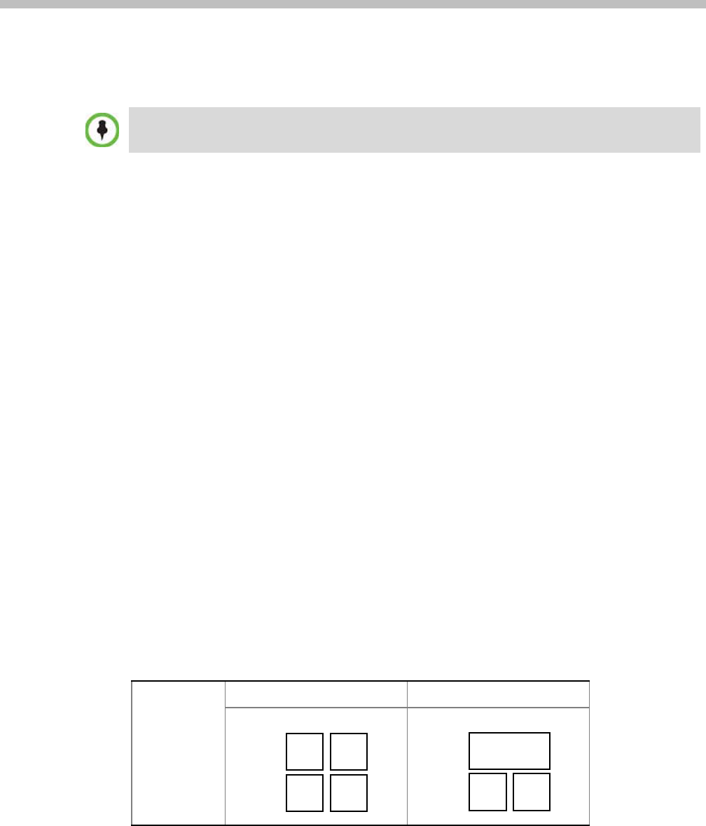
Polycom, Inc. 5-1
5
Cascading Conferences
Cascading enables administrators to connect one conference directly to one or several
conferences, depending on the topology, creating one large conference. The conferences can
run on the same MCU or different MCUs.
There are many reasons for cascading conferences, the most common are:
• Connecting two conferences on different MCUs at different sites.
• Utilizing the connection abilities of different MCUs, for example, different
communication protocols.
The following cascading topologies are available for cascading:
•Basic Cascading - only two conferences are connected (usually running on two
different Collaboration Servers). The cascaded MCUs reside on the same network.
•Star Cascading - one or several conferences are connected to one master conference.
Conferences are usually running on separate MCUs. The cascaded MCUs reside on the
same network.
System configuration and feature availability change according to the selected cascading
topology.
Video Layout in Cascading conferences (CP and mixed CP and SVC)
Cascade links are treated as endpoints in CP conferences and are allocated resources
according to "Resolution Configuration for CP Conferences” on page 4-8. Cascaded links in 1x1
video layout are in SD resolution.
When cascading two conferences, the video layout displayed in the cascaded conference is
determined by the selected layout in each of the two conferences. Each of the two
conferences will inherit the video layout of the other conference in one of their windows.
In order to avoid cluttering in the cascaded window, it is advised to select appropriate video
layouts in each conference before cascading them.
Cascading information applies to AVC Conferencing Mode (CP and mixed CP and SVC) only.
Cascading is not supported with SVC Conferencing Mode.
Without
Cascade
Conference A Conference B

Polycom® RealPresence Collaboration ServerVirtual Edition Administrator’s Guide
5-2 Polycom, Inc.
Figure 5-1 Video Layouts in Cascaded Conferences
Guidelines
To ensure that conferences can be cascaded and video can be viewed in all conferences the
following guidelines are recommended:
• The same version installed on all MCUs participating the cascading topology
• The same license installed on all MCUs participating the cascading topology
• Same Conference Parameters are defined in the Profile of the conferences participating
in the cascading topology
—Conference line rates should be identical
—Content rate should be identical
—Same encryption settings
• DTMF codes should be defined with the same numeric codes in the IVR services
assigned to the cascading conferences
• DTMF forwarding is suppressed
• The video layout of the link is set to 1x1 by the appropriate system flag.
• When the Mute Participants Except Lecturer option is enabled in the Conference
Profile, all participants (including the link participants) except the lecturer are muted.
Only the lecturer is not muted.
Flags controlling Cascade Layouts
• Setting the FORCE_1X1_LAYOUT_ON_CASCADED_LINK
_CONNECTION System Flag to YES (default) automatically forces the cascading link to
Full Screen (1x1) in CP conferences, hence displaying the speaker of one conference to a
full window in the video layout of the other conference.
Set this flag to NO when cascading between an Collaboration Server and an MGC that
is functioning as a Gateway, if the participant layouts on the MGC are not to be forced
to 1X1.
• Setting the AVOID_VIDEO_LOOP_BACK_IN_CASCADE System Flag to YES
(default) prevents the speaker’s image from being sent back through the participant
link from the cascaded conference. This can occur in cascaded conferences with
conference layouts other than 1x1. It results in the speaker’s own video image being
displayed in the speaker’s video layout.
This option is supported with Basic Cascading. If a Master MCU has two slave MCUs,
participants connected to the slave MCUs will not receive video from each other.
For more details on defining system flags, see "Modifying System Flags” on page 20-1.
During
Cascading
Video layout of Conf. B in
window of Conf. A
Video layout of Conf. A in
window of Conf. B
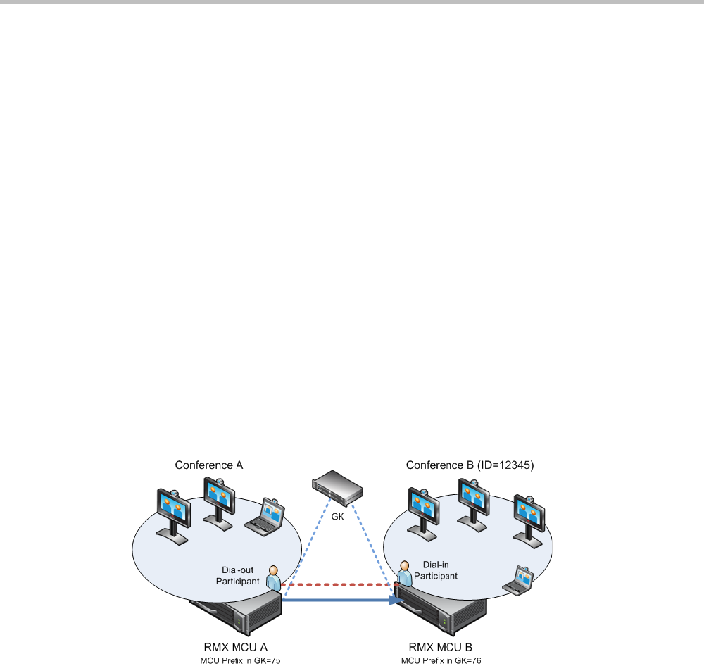
Chapter 5-Cascading Conferences
Polycom, Inc. 5-3
Basic Cascading
In this topology, a link is created between two conferences, usually running on two different
MCUs. The MCUs are usually installed at different locations (states/countries) to save long
distance charges by connecting each participant to their local MCU, while only the link
between the two conferences is billed as long distance call.
• This is the only topology that enables IP cascading links:
—When linking two conferences using an IP connection, the destination MCU can be
indicated by:
•IP address
•H.323 Alias
—If IP cascading link is used to connect the two conferences, both MCUs must be
located in the same network.
• One MCU can be used as a gateway.
• The configuration can include two Collaboration Servers.
Basic Cascading using IP Cascaded Link
In this topology, both MCUs can be registered with the same gatekeeper or the IP addresses
of both MCUs can be used for the cascading link. Content can be sent across the Cascading
Link.
Figure 5-2 Basic Cascading Topology - IP Cascading Link
For example, MCU B is registered with the gatekeeper using 76 as the MCU prefix.
The connection between the two conferences is created when a dial out IP participant is
defined (added) to conference A whose dial out number is the dial-in number of the
conference or Entry Queue running on MCU B.
Dialing Directly to a Conference
Dial out IP participant in conference A dials out to the conference running on MCU B
entering the number in the format:
[MCU B Prefix/IP address][conference B ID].
For example, if MCU B prefix is 76 and the conference ID is 12345, the dial number is
7612345.

Polycom® RealPresence Collaboration ServerVirtual Edition Administrator’s Guide
5-4 Polycom, Inc.
Automatic Identification of the Cascading Link
The system automatically identifies that the dial in participant is an MCU and creates a
Cascading Link and displays the link icon for the participant ( ). The master-slave
relationship is randomly defined by the MCUs during the negotiation process of the
connection phase.

Polycom, Inc. 6-1
6
Meeting Rooms
A Meeting Room is a conference saved on the MCU in passive mode, without using any of
the system resources. A Meeting Room is automatically activated when the first participant
dials into it. Meeting Rooms can be activated as many times as required. Once activated, a
Meeting Room functions as any ongoing conference.
The conferencing Mode of the Meeting Room is determined by the Profile assigned to it.
In SVC Conferencing Mode, dial-in is available as follows:
• AVC-capable endpoints (participants) can only connect to an AVC CP Meeting Room.
When dialing into SVC Only Meeting Room the calls fail.
• SVC-capable endpoints support both AVC and SVC video protocols. When dialing into
SVC Only conferences, they connect as SVC endpoints. When dialing into AVC CP
Only conferences, they connect as AVC endpoints.
• Both AVC and SVC endpoints can connect to a mixed CP and SVC conference.
In AVC CP Conferences, dial-out participants can be connected to the conference
automatically, or manually. In the automatic mode the system calls all the participants one
after the other. In the manual mode, the Collaboration Server user or meeting organizer
instructs the conferencing system to call the participant. Dial-out participants must be
defined (mainly their name) and added to the conference. This mode can only be selected at
the conference/Meeting Room definition stage and cannot be changed once the conference
is ongoing.
A Meeting Room can be designated as a Permanent Conference. For more information see
"Audio Algorithm Support” on page 3-45.
The maximum of number of Meeting Rooms that can be defined is 1000.
The system is shipped with four default Meeting Rooms as shown in Table 6-1.
Table 6-1 Default Meeting Rooms List
Meeting Room Name ID Default Line Rate
Maple_Room 1001 1920 Kbps
Oak_Room 1002 1920 Kbps
Juniper_Room 1003 1920 Kbps
Fig_Room 1004 1920 Kbps
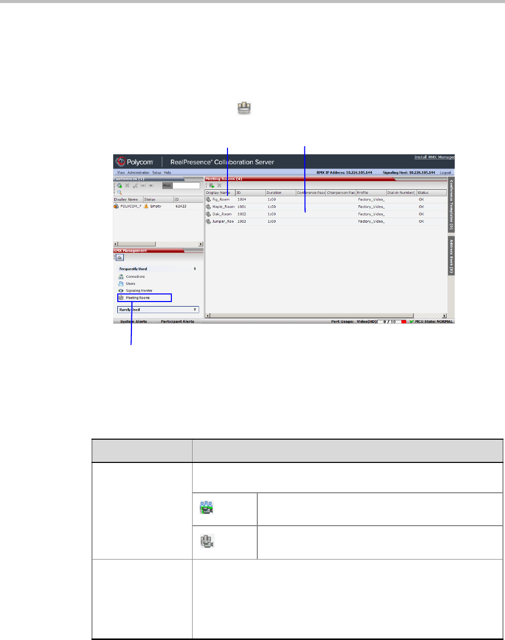
Polycom® RealPresence Collaboration ServerVirtual Edition Administrator’s Guide
6-2 Polycom, Inc.
Meeting Rooms List
Meeting Rooms are listed in the Meeting Room list pane.
To list Meeting Rooms:
>> In the RealPresence Collaboration Server Management pane, in the Frequently Used list, click
the Meeting Rooms button .
The Meeting Rooms List is displayed.
An active Meeting Room becomes an ongoing conference and is monitored in the same way
as any other conference.
The Meeting Room List columns include:
Table 6-2 Meeting Rooms List Columns
Field Description
Display Name Displays the name and the icon of the Meeting Room in the Collaboration
Server Web Client.
(green)
An active video Meeting Room that was activated when
the first participant connected to it.
(gray)
A passive video Meeting Room that is waiting to be
activated.
Routing Name The ASCII name that registers conferences, Meeting Rooms, Entry
Queues and SIP Factories in the various gatekeepers and SIP Servers. In
addition, the Routing Name is also:
•The name that endpoints use to connect to conferences.
•The name used by all conferencing devices to connect to conferences
that must be registered with the gatekeeper and SIP Servers.
Meeting Room Toolbar Meeting Room List
Access to Meeting Rooms

Chapter 6-Meeting Rooms
Polycom, Inc. 6-3
ID Displays the Meeting Room ID. This number must be communicated to
H.323 conference participants to enable them to dial in.
Duration Displays the duration of the Meeting Room in hours using the format
HH:MM (default 01:00).
Conference
Password
The password to be used by participants to
access the Meeting Room. If blank, no password
is assigned to the conference. This password is
valid only in conferences that are configured to
prompt for a conference password in the IVR
Service.
The Collaboration
Server can be
configured to
automatically
generate conference
and chairperson
passwords when
these fields are left
blank.
For more information,
see the "Automatic
Password Generation
Flags” on
page 20-37.
Chairperson
Password
Displays the password to be used by the users to
identify themselves as Chairpersons. They are
granted additional privileges. If left blank, no
chairperson password is assigned to the
conference. This password is valid only in
conferences that are configured to prompt for a
chairperson password.
Profile Displays the name of the Profile assigned to the Meeting Room. For more
information, see "Defining New Profiles” on page 2-9.
SIP Registration The status of registration with the SIP server:
•Not configured - Registration with the SIP Server was not enabled in
the Conference Profile assigned to this conferencing Entity. In Multiple
Networks configuration, If one service is not configured while others
are configured and registered, the status reflects the registration with
the configured Network Services. The registration status with each SIP
Server can be viewed in the Properties - Network Services dialog box
of each conferencing entity.
When SIP registration is not enabled in the conference profile, the
Collaboration Server's registering to SIP Servers will each register with
an URL derived from its own signaling address.
•Failed - Registration with the SIP Server failed. This may be due to
incorrect definition of the SIP server in the IP Network Service, or the
SIP server may be down, or any other reason the affects the
connection between the Collaboration Server or the SIP Server to the
network.
•Registered - the conferencing entity is registered with the SIP Server.
•Partially Registered - This status is available only in Multiple
Networks configuration, when the conferencing entity failed to register
to all the required Network Services if more than one Network Service
was selected.
Table 6-2 Meeting Rooms List Columns (Continued)
Field Description
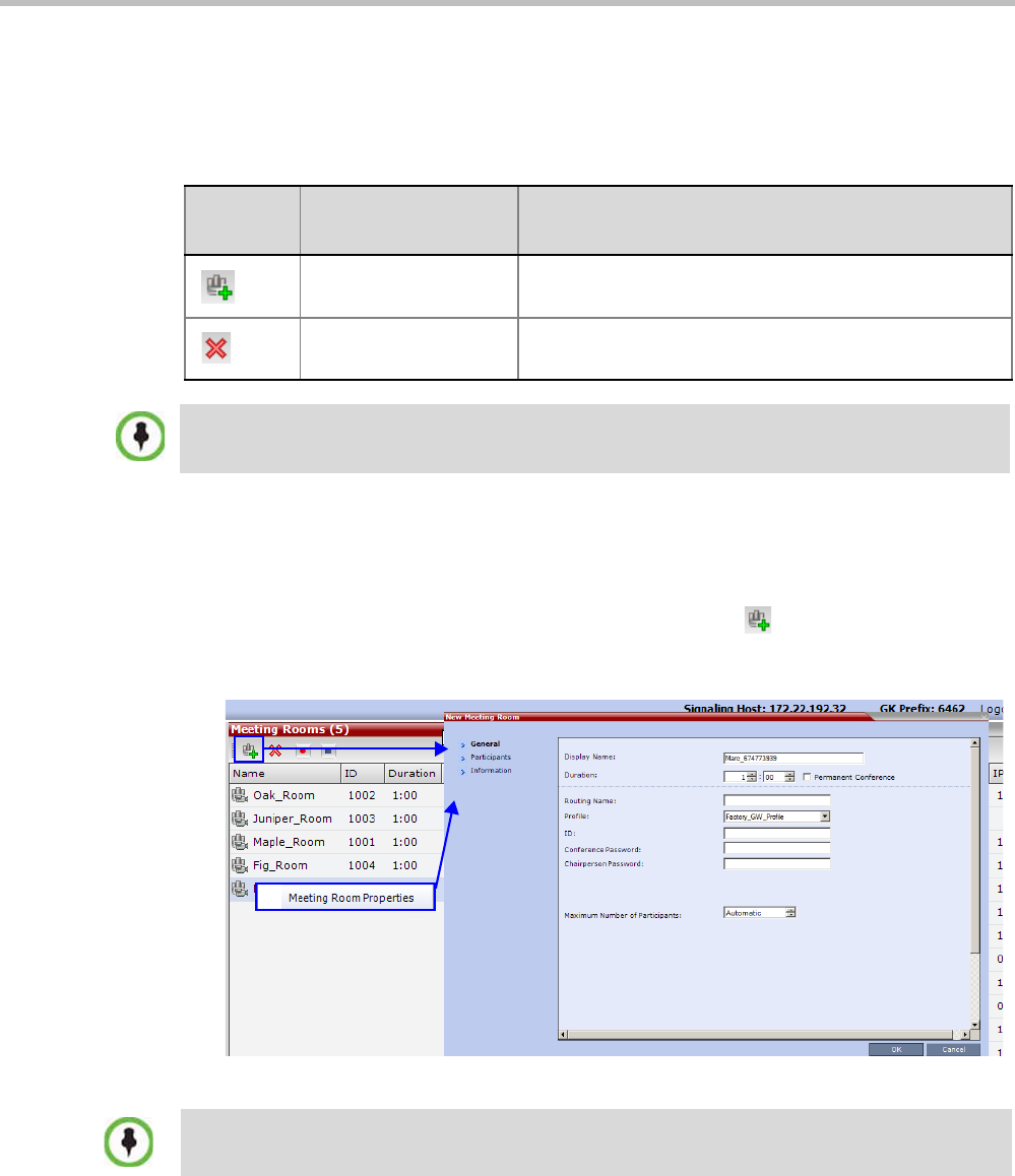
Polycom® RealPresence Collaboration ServerVirtual Edition Administrator’s Guide
6-4 Polycom, Inc.
Meeting Room Toolbar & Right-click Menu
The Meeting Room toolbar and right-click menus provide the following functionality:
Creating a New Meeting Room
To create a new meeting room:
>> In the Meeting Rooms pane, click the New Meeting Room button or right-click an
empty area in the pane and then click New Meeting Room.
The New Meeting Room dialog box is displayed.
The definition procedure is the same as for the new conference.
For more information, see the Polycom® RealPresence Collaboration Server Virtual Edition
Getting Started Guide, "Starting an AVC CP Conference from the Conferences Pane” on
page 3-13.
Table 6-3 Meeting Room Toolbar and Right-click Menus
Toolbar
button Right-click menu Description
New Meeting Room Select this button to create a new Meeting Room.
Delete Meeting Room Select any Meeting Room and then click this button to
delete the Meeting Room.
Dial out to AVC participants assigned to a Meeting Room will only start when the dial in participant
who has activated it has completed the connection process and the Meeting Room has become an
ongoing conference.
If SIP Factories are being used do not assign a Meeting Room the ID 7001. This ID is reserved for
the default SIP Factory.

Chapter 6-Meeting Rooms
Polycom, Inc. 6-5
Microsoft Lync users can connect a Collaboration Server Meeting Room to a conference
running on the Microsoft A/V MCU. This allows Collaboration Server Lync users to
connect with a conference in progress on the A/V MCU and be an active participant in
the conference.
For more information, see "Connecting a Collaboration Server Meeting Room to a Microsoft
AV-MCU Conference” on page G-31.

Polycom® RealPresence Collaboration ServerVirtual Edition Administrator’s Guide
6-6 Polycom, Inc.

Polycom, Inc. 7-1
7
Entry Queues, Ad Hoc Conferences
and SIP Factories
Entry Queues
An Entry Queue (EQ) is a special routing lobby to access conferences. Participants connect
to a single-dial lobby and are routed to their destination conference according to the
Conference ID they enter. The Entry Queue remains in a passive state when there are no
callers in the queue (in between connections) and is automatically activated once a caller
dials its dial-in number.
Participants can be moved from the Entry Queue and the destination conference if both
conferencing entities are set to the same conferencing parameters: Conferencing Mode, Line
rate and video parameters. For example, participants can be moved from SVC Only Entry
Queue to SVC Only conference, or from a mixed CP and SVC Entry Queue to a mix CP and
SVC conference, from CP only Entry Queue to CP only conference.
The maximum of number of Entry Queues that can be defined is 40.
The parameters (bit rate and video properties) with which the participants connect to the
Entry Queue and later to their destination conference are defined in the Conference Profile
that is assigned to the Entry Queue. For example, if the Profile Bit Rate is set to 384kbps, all
endpoints connect to the Entry Queue and later to their destination conference using this bit
rate even if they are capable of connecting at higher bit rates.
An Entry Queue IVR Service must be assigned to the Entry Queue to enable the voice
prompts guiding the participants through the connection process. The Entry Queue IVR
Service also includes a video slide that is displayed to the participants while staying in the
Entry Queue (during their connection process).
Different Entry Queues can be created to accommodate different conferencing modes,
conferencing parameters (by assigning different Profiles) and prompts in different
languages (by assigning different Entry Queue IVR Services).
For more information, see "IVR Services List” on page 16-1.
The Entry Queue can also be used for Ad Hoc conferencing. If the Ad Hoc option is enabled
for the Entry Queue, when the participant enters the target conference ID the system checks
whether a conference with that ID is already running on the MCU. If not, the system
automatically creates a new ongoing conference with that ID. For more information about
Ad Hoc conferencing, see "Ad Hoc Conferencing” on page 7-11.
An Entry Queue can be designated as Transit Entry Queue to which calls with dial
strings
containing incomplete or incorrect conference routing information are transferred.
For more
information, see "Transit Entry Queue” on page 7-6.

Polycom® RealPresence Collaboration ServerVirtual Edition Administrator’s Guide
7-2 Polycom, Inc.
Default Entry Queue properties
The system is shipped with a default Entry Queue whose properties are:
Table 7-1 Default Entry Queue Properties
Parameter Value
Display Name DefaultEQ
The user can change the name if required.
Routing Name DefaultEQ
The default Routing Name cannot be changed.
ID 1000
Profile name Factory_Mixd_CP_SVC_Video_Profile. Profile Bit Rate is set to
1920Kbps.
Entry Queue Service Entry Queue IVR Service. This is default Entry Queue IVR Service
shipped with the system and includes default voice messages and
prompts in English.
Ad Hoc Enabled
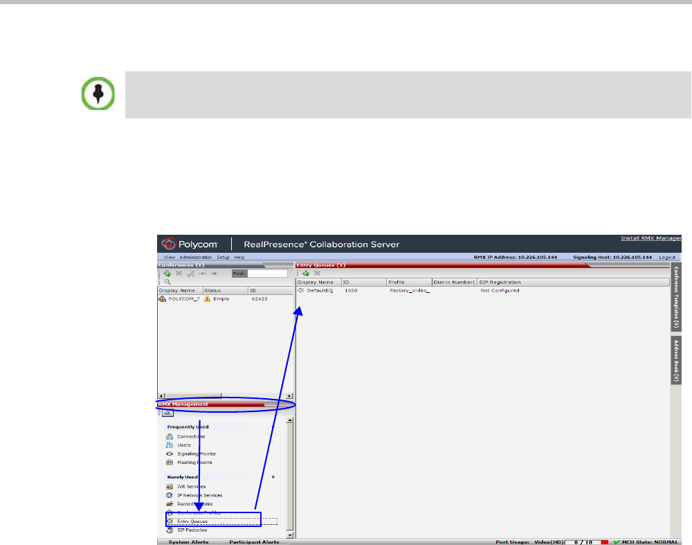
Chapter 7-Entry Queues, Ad Hoc Conferences and SIP Factories
Polycom, Inc. 7-3
Defining a New Entry Queue
You can modify the properties of the default Entry Queue and define additional Entry
Queues to suit different conferencing requirements.
To define a new Entry Queue:
1In the RealPresence Collaboration Server Management - Rarely Used pane, click Entry
Queues.
In the RealPresence CloudAxis Solution, virtual Entry Queues and ad-hoc conferences are defined
in the RealPresence DMA system component and should not be defined directly in the
RealPresence Collaboration Server Virtual Edition component.
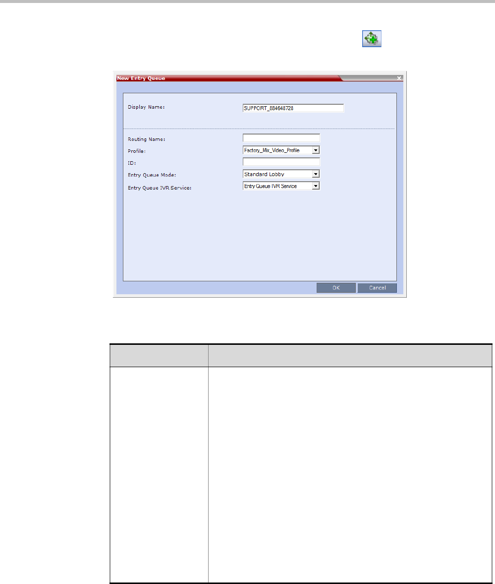
Polycom® RealPresence Collaboration ServerVirtual Edition Administrator’s Guide
7-4 Polycom, Inc.
2In the Entry Queues list pane, click the New Entry Queue button.
The New Entry Queue dialog box opens.
3Define the following parameters:
Table 7-2: Entry Queue Definitions Parameters
Option Description
Display Name The Display Name is the conferencing entity name in native language
character sets to be displayed in the Collaboration Server Web
Client.
In conferences, Meeting Rooms, Entry Queues and SIP factories the
system automatically generates an ASCII name for the Display Name
field that can be modified using Unicode encoding.
•English text uses ASCII encoding and can contain the most
characters (length varies according to the field).
•European and Latin text length is approximately half the length of
the maximum.
•Asian text length is approximately one third of the length of the
maximum.
The maximum length of text fields also varies according to the
mixture of character sets (Unicode and ASCII).
Maximum field length in ASCII is 80 characters. If the same name is
already used by another conference, Meeting Room or Entry Queue,
the Collaboration Server displays an error message requesting you to
enter a different name.

Chapter 7-Entry Queues, Ad Hoc Conferences and SIP Factories
Polycom, Inc. 7-5
4Click OK.
The new Entry Queue is added to the Entry Queues list.
Routing Name Enter a name using ASCII text only. If no Routing Name is entered,
the system automatically assigns a new name as follows:
•If an all ASCII text is entered in Display Name, it is used also as
the Routing Name.
•If any combination of Unicode and ASCII text (or full Unicode text)
is entered in Display Name, the ID (such as Conference ID) is
used as the Routing Name.
Profile Select the Profile to be used by the Entry Queue. The default Profile
is selected by default. This Profile determines the Bit Rate and the
video properties with which participants connect to the Entry Queue
and destination conference.
In Ad Hoc conferencing, it is used to define the new conference
properties.
ID Enter a unique number identifying this conferencing entity for dial in.
Default string length is 4 digits.
If you do not manually assign the ID, the MCU assigns one after the
completion of the definition. The ID String Length is defined by the
flag NUMERIC_CONF_ID_LEN in the System Configuration.
Entry Queue Mode Select the mode for the Entry Queue:
Standard Lobby (default)-When selected, the Entry Queue is used
as a routing lobby to access conferences. Participants connect to a
single-dial lobby and are routed to their destination conference
according to the Conference ID they enter.
Ad Hoc - Select this option to enable the Ad Hoc option for this Entry
Queue. In this mode, when the participant enters the target
conference ID the system checks whether a conference with that ID
is already running on the MCU. If not, the system automatically
creates a new ongoing conference with that ID.
IVR Service Provider Only - When selected, designates this Entry
Queue as a special Entry Queue that provides IVR Services to SIP
calls on behalf of the RealPresence DMA system. The IVR service
provider only Entry Queue does not route the SIP calls to a target
conference. Instead the RealPresence DMA system handles the call.
For more details, see "” on page 7-7.
External IVR Control - Not Supported with RealPresence
Collaboration Server Virtual Edition.
Entry Queue IVR
Service
The default Entry Queue IVR Service is selected. If required, select
an alternate Entry Queue IVR Service, which includes the required
voice prompts, to guide participants during their connection to the
Entry Queue.
Table 7-2: Entry Queue Definitions Parameters (Continued)
Option Description
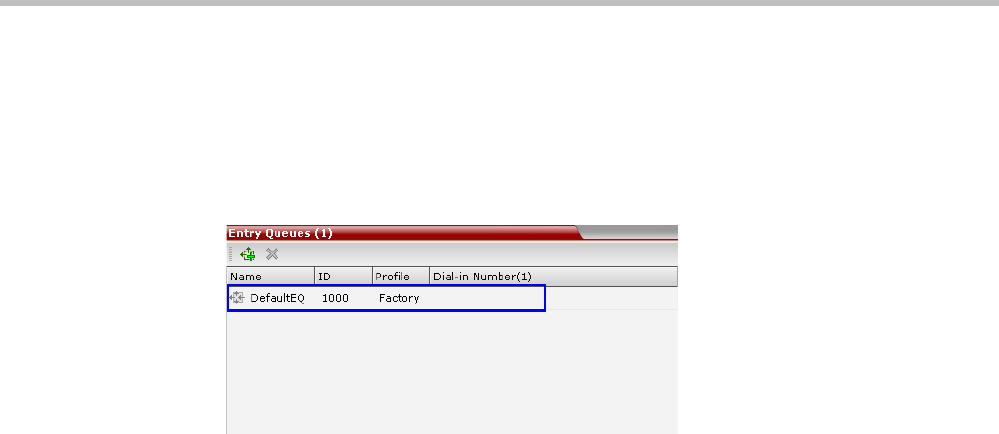
Polycom® RealPresence Collaboration ServerVirtual Edition Administrator’s Guide
7-6 Polycom, Inc.
Listing Entry Queues
To view the list of Entry Queues:
>> In the RealPresence Collaboration Server Management - Rarely Used pane, click Entry
Queues.
The Entry Queues are listed in the Entry Queues pane.
You can double-click an Entry Queue to view its properties.
Modifying the EQ Properties
To modify the EQ:
>> In the Entry Queues pane, either double-click or right-click and select Entry Queue
Properties of the selected Entry Queue in the list.
The Entry Queue Properties dialog box is displayed. All the fields may be modified
except Routing Name.
Transit Entry Queue
A Transit Entry Queue is an Entry Queue to which calls with dial
strings containing
incomplete or incorrect conference routing information are transferred.
IP Calls are routed to the Transit Entry Queue when:
• A gatekeeper is not used, or where calls are made directly to the Collaboration Server’s
Signaling IP Address, with incorrect or without a Conference ID.
• When a gatekeeper is used and only the prefix of the Collaboration Server is dialed,
with incorrect or without a Conference ID.
• When the dialed prefix is followed by an incorrect conference ID.
When no Transit Entry Queue is defined, all calls containing incomplete or incorrect
conference routing information are rejected by the Collaboration Server.
In the Transit Entry Queue, the Entry Queue IVR Service prompts the participant for a
destination conference ID. Once the correct information is entered, the participant is
transferred to the destination conference.
Setting a Transit Entry Queue
The Collaboration Server factory default settings define the Default Entry Queue also as the
Transit Entry Queue. You can designate another Entry Queue as the Transit Entry Queue.
Only one Transit Entry Queue may be defined per Collaboration Server and selecting another
Entry Queue as the Transit Entry Queue automatically cancels the previous selection.
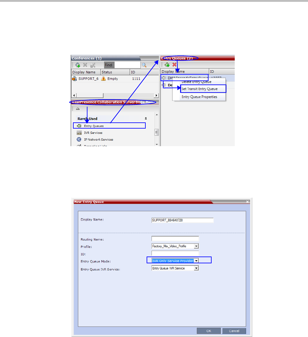
Chapter 7-Entry Queues, Ad Hoc Conferences and SIP Factories
Polycom, Inc. 7-7
To designate an Entry Queue as Transit Entry Queue:
1In the Collaboration Server Management - Rarely Used pane, click Entry Queues.
2In the Entry Queues list, right-click the Entry Queue entry and then click Set Transit
Entry Queue.
The Entry Queue selected as Transit Entry Queue is displayed in bold.
To cancel the Transit Entry Queue setting:
1In the Collaboration Server Management - Rarely Used pane click Entry Queues.
2In the Entry Queues list, right-click the Transit Entry Queue entry and then click Cancel
Transit Entry Queue.
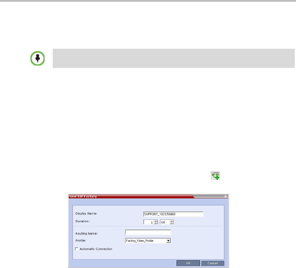
Polycom® RealPresence Collaboration ServerVirtual Edition Administrator’s Guide
7-8 Polycom, Inc.
SIP Factories
A SIP Factory is a conferencing entity that enables SIP endpoints to create Ad Hoc
conferences. The system is shipped with a default SIP Factory, named DefaultFactory.
When a SIP endpoint calls the SIP Factory URI, a new conference is automatically created
based on the Profile parameters, and the endpoint joins the conference.
The SIP Factory URI must be registered with the SIP server to enable routing of calls to the
SIP Factory. To ensure that the SIP factory is registered, the option to register Factories must
be selected in the Default IP Network Service.
The maximum of number of SIP Factories that can be defined is 40.
Creating SIP Factories
To create a new SIP Factory:
1In the RealPresence Collaboration Server Management - Rarely Used pane, click SIP
Factories.
2In the SIP Factories list pane, click the New SIP Factory button.
The New Factory dialog box opens.
The default SIP Factory uses the conferencing ID 7001. If a SIP Factory is being used do not assign
this ID to any conferencing entity, including conferences, and meeting rooms.

Chapter 7-Entry Queues, Ad Hoc Conferences and SIP Factories
Polycom, Inc. 7-9
3Define the following parameters:
4Click OK.
The new SIP Factory is added to the list.
Table 7-3: New Factory Properties
Option Description
Display Name Enter the SIP Factory name that will be displayed.
The Display Name is the conferencing entity name in native language
character sets to be displayed in the Collaboration Server Web Client.
In conferences, Meeting Rooms, Entry Queues and SIP factories the
system automatically generates an ASCII name for the Display Name
field that can be modified using Unicode encoding.
•English text uses ASCII encoding and can contain the most
characters (length varies according to the field).
•European and Latin text length is approximately half the length of
the maximum.
•Asian text length is approximately one third of the length of the
maximum.
The maximum length of text fields also varies according to the
mixture of character sets (Unicode
and ASCII).
Maximum field length in ASCII is 80 characters. If the same name is
already used by another conference, Meeting Room or Entry Queue,
the Collaboration Server displays an error message requesting you to
enter a different name.
Routing Name The Routing Name is defined by the user, however if no Routing
Name is entered, the system will automatically assign a new name
when the Profile is saved as follows:
•If an all ASCII text is entered in Display Name, it is used also as
the Routing Name.
•If any combination of Unicode and ASCII text (or full Unicode text)
is entered in Display Name, the ID (such as Conference ID) is
used as the Routing Name.
Profile The default Profile is selected by default. If required, select the
conference Profile from the list of Profiles defined in the MCU.
A new conference is created using the parameters defined in the
Profile.
Automatic
Connection
Select this check box to immediately accept the conference creator
endpoint to the conference. If the check box is cleared, the endpoint
is redirected to the conference and then connected.
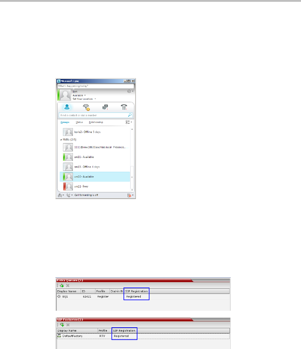
Polycom® RealPresence Collaboration ServerVirtual Edition Administrator’s Guide
7-10 Polycom, Inc.
SIP Registration & Presence for Entry Queues and SIP
Factories
Entry Queues and SIP Factories can be registered with SIP servers. This enables Office
Communication Server or Lync server client users to see the availability status (Available,
Offline, or Busy) of these conferencing entities and to connect to them directly from the
Buddy List.
Guidelines
•The Entry Queue or SIP Factory must be added to the Active Directory as a User.
•SIP Registration must be enabled in the Profile assigned to the Entry Queue or SIP Factory.
For more information see Step of "Defining New Profiles” on page 2-20.
Monitoring Registration Status
The SIP registration status can be viewed in the Entry Queue or SIP Factory list panes.
The following statuses are displayed:
•Not configured - Registration with the SIP Server was not enabled in the Conference
Profile assigned to the Entry Queue or SIP Factory.

Chapter 7-Entry Queues, Ad Hoc Conferences and SIP Factories
Polycom, Inc. 7-11
When SIP registration is not enabled in the conference profile, the Collaboration
Server's registering to SIP Servers will each register with an URL derived from its own
signaling address.
•Failed - Registration with the SIP Server failed.
This may be due to incorrect definition of the SIP server in the IP Network Service, or the
SIP Server may be down, or any other reason the affects the connection between the
Collaboration Server or the SIP Server to the network.
•Registered - the conferencing entity is registered with the SIP Server.
•Partially Registered - This status is available only in Multiple Networks configuration,
when the conferencing entity failed to register to all the required Network Services if
more than one Network Service was selected for Registration.
Ad Hoc Conferencing
The Entry Queue can also be used for Ad Hoc conferencing. If the Ad Hoc option is enabled
for the Entry Queue, when the participant enters the target conference ID the system checks
whether a conference with that ID is already running on the MCU. If not, the system
automatically creates a new ongoing conference with that ID. The conference parameters are
based on the Profile linked to the Entry Queue. As opposed to Meeting Rooms, that are
predefined conferences saved on the MCU, Ad Hoc conferences are not stored on the MCU.
Once an Ad Hoc conference is started it becomes an ongoing conference, and it is monitored
and controlled as any standard ongoing conference.
An external database application can be used for authentication with Ad Hoc conferences.
The authentication can be done at the Entry Queue level and at the conference level. At the
Entry Queue level, the MCU queries the external database server whether the participant
has the right to create a new conference. At the conference level the MCU verifies whether
the participant can join the conference and if the participant is the conference chairperson.
The external database can populate certain conference parameters.
For more information about Ad Hoc conferencing, see Appendix D, "Ad Hoc Conferencing and
External Database Authentication” on page D-1.

Polycom® RealPresence Collaboration ServerVirtual Edition Administrator’s Guide
7-12 Polycom, Inc.

Polycom, Inc. 8-1
8
Address Book
The Address Book stores information about the people and businesses you communicate
with. The Address Book stores, among many other fields, IP addresses, phone numbers and
network communication protocols used by the participant’s endpoint. By utilizing the
Address Book you can quickly and efficiently assign or designate participants to
conferences. Groups defined in the Address Book help facilitate the creation of conferences.
Participants can be added to the Address Book individually or in Groups.
The maximum of number of Address Book entries that can be defined on the Collaboration
Server is 4000.
When using the Polycom CMA/RealPresence Resource Manager Global Address Book, all
entries are listed.
The Address Book can be organized into a multi-level hierarchical structure. It can be used
to mirror the organizational layout of the enterprises and it is especially suitable for large-
scale enterprises with a considerable number of conference participants and organizational
departments and divisions. Groups in the Address Book can contain sub-groups or sub-
trees, and individual address book participant entities.
The Address Book provides flexibility in arranging conference participants into groups in
multiple levels and the capabilities to add groups or participants, move or copy participants
to multiple groups within the address book, and use the address book to add groups and
participants to a conference or Conference Template.
Importing and exporting of Address Books enables organizations to seamlessly distribute
up-to-date Address Books to multiple Collaboration Server units. It is not possible to
distribute Address Books to external databases running on applications such as Polycom’s
RealPresence Resource Manager (XMA) or Polycom CMA. External databases can run in
conjunction with Collaboration Server units, but must be managed from the external
application. For example, new participants cannot be added to the external database from
the Collaboration Server Web Client. To enable the Collaboration Server to run with an
external database such as Polycom RealPresence Resource Manager (XMA) or CMA, the
appropriate system configuration flags must be set.
For more information, see "Modifying System Flags” on page 20-1.
Integration with the Global Address Book of the Polycom RealPresence Resource Manager (XMA)
or CMA is supported. For more information, see "Integrating the Global Address Book (GAB) of
Polycom RealPresence Resource Manager (XMA) or Polycom CMA™ with the Collaboration
Server” on page 8-23. Integration with the SE200 GAB (Global Address Book) is not supported.
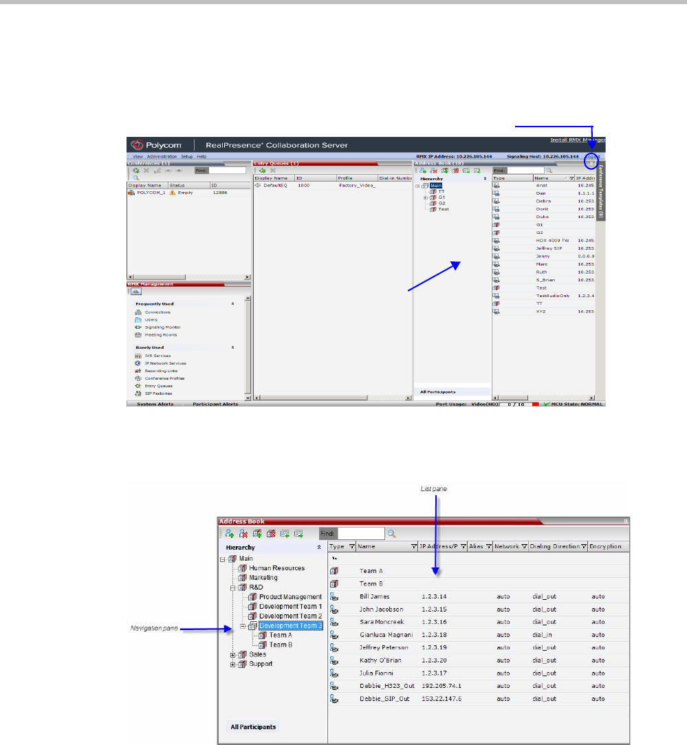
Polycom® RealPresence Collaboration ServerVirtual Edition Administrator’s Guide
8-2 Polycom, Inc.
Viewing the Address Book
You can view the participants currently defined in the Address Book. The first time the
Collaboration Server Web Client is accessed, the Address Book pane is displayed.
The Address Book contains two panes:
•Navigation pane - contains the hierarchical tree and All Participants list
•List pane - displays the list of all the members of the selected group and sub-groups.
The Navigation pane of the Address Book contains the following types of lists:
•Hierarchical — displays a multi-level hierarchical tree of groups and participants.
Double-clicking a group on the navigation pane displays the group participants and
sub-groups in the List pane.
•All Participants — double-clicking this selection displays the single unique entity of all
the participants in a single level. When adding a participant to a group, the system adds
a link to the participant’s unique entity that is stored in the All Participants list. The
same participant may be added to many groups at different levels, and all these
Address Book pane
Anchor Pin
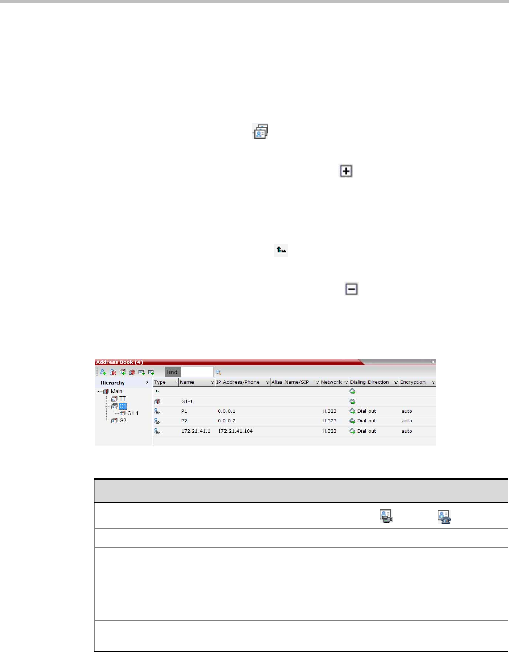
Chapter 8-Address Book
Polycom, Inc. 8-3
participant links are associated with the same definition of the participant in the All
Participants list. If the participant properties are changed in one group, they will be
changed in all the groups accordingly.
Displaying and Hiding the Group Members in the Navigation Pane
The currently selected group, whose group members are displayed in the Address Book List
pane is identified by a special icon .
To expand the group to view the group members:
>> Double-click the group name or click the Expand button.
The address book entities and sub-groups of the group is displayed in the right group
list pane. You can drill down the sub-group to view address book entities in the sub-
group.
To move up to the next level and view the members in the upper level:
>> Double-click the navigation arrow button in the group members pane.
To collapse a group:
>> Double-click the group name or click the Collapse button.
Participants List Pane Information
The Participants List pane displays the following information for each participant:
Table 8-1 Docked Address Book List Columns
Field/Option Description
Type Indicates whether the participant is a video ( ) or voice ( ).
Name Displays the name of the participant.
IP Address/Phone Enter the IP address of the participant’s endpoint.
•For H.323 participant define either the endpoint IP address or alias.
•For SIP participant define either the endpoint IP address or the SIP
address.
Network The network communication protocol used by the endpoint to connect to
the conference: H.323 or SIP .
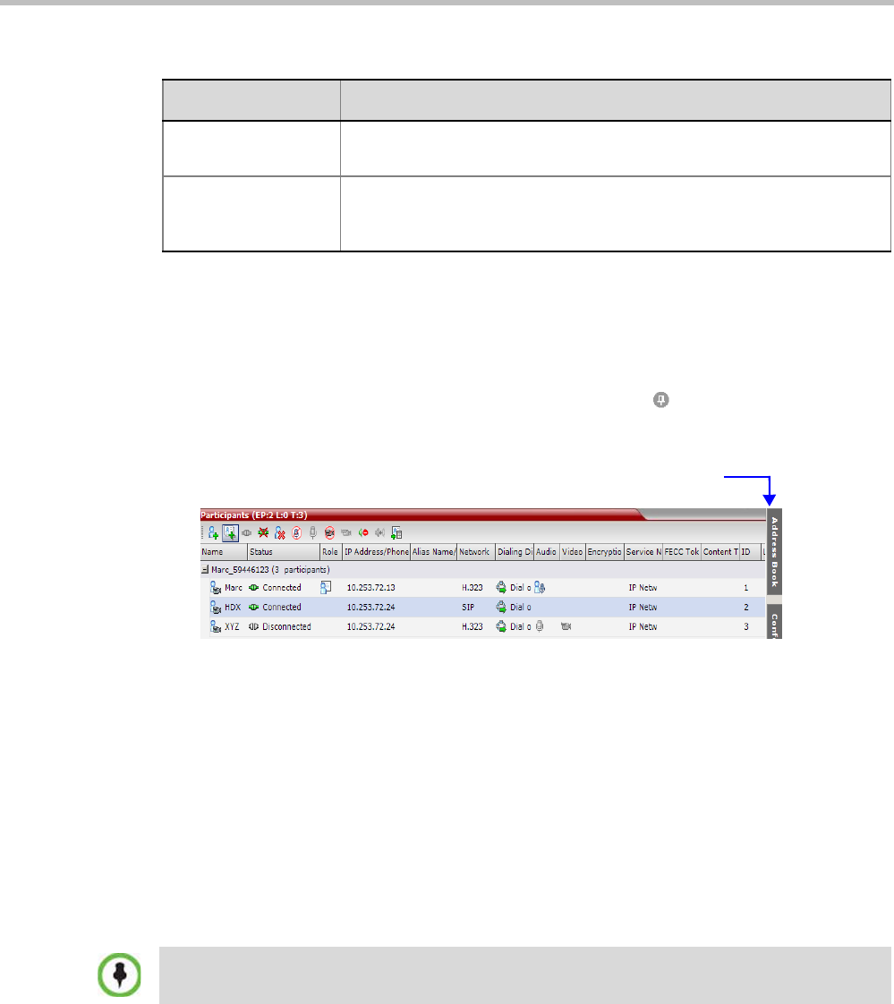
Polycom® RealPresence Collaboration ServerVirtual Edition Administrator’s Guide
8-4 Polycom, Inc.
For information on adding and modifying participants in the Address Book, see "Managing
the Address Book” on page 8-7.
Displaying and Hiding the Address Book
The Address Book can be hidden it by clicking the anchor pin ( ) button in the pane header.
The Address Book pane closes and a tab is displayed at the right edge of the screen.
>> Click the tab to re-open the Address Book.
Adding Participants from the Address Book to
Conferences
You can add individual participants or a group of participants from the Address Book to a
conference.
Adding Individual Participants from the Address Book to Conferences
You can add a participant or multiple participants to a new conference, ongoing
conferences, or to Conference Templates by using the drag-and-drop operation.
To add a participant to a new conference or an ongoing conference:
1In the Address Book Navigation pane, select the group from which to add participants.
2In the Address Book List pane, select the participant or participants you want to add to
the conference.
Dialing Direction Dial-in – The participant dials in to the conference.
Dial-out – The Collaboration Server dials out to the participant.
Encryption Displays whether the endpoint uses encryption for its media.
The default setting is Auto, indicating that the endpoint must connect
according to the conference encryption setting.
Table 8-1 Docked Address Book List Columns (Continued)
Field/Option Description
Click tab to open Address Book
Multiple selection of group levels is not available.

Chapter 8-Address Book
Polycom, Inc. 8-5
3Click and hold the left mouse button and drag the selection to the Participants pane of
the conference.
The participants are added to the conference.
Adding a Group from the Address Book to Conferences
You can add a group of participants to a new conference, ongoing conferences, or to
Conference Templates by using the drag-and-drop operation.
To add a group to a new conference or an ongoing conference:
1In the Address Book Navigation pane, select the group you want to add to the conference.
2Click and hold the left mouse button and drag the selection to the Participants pane of
the conference.
The participants in the group level and all sub-levels are added to the conference.
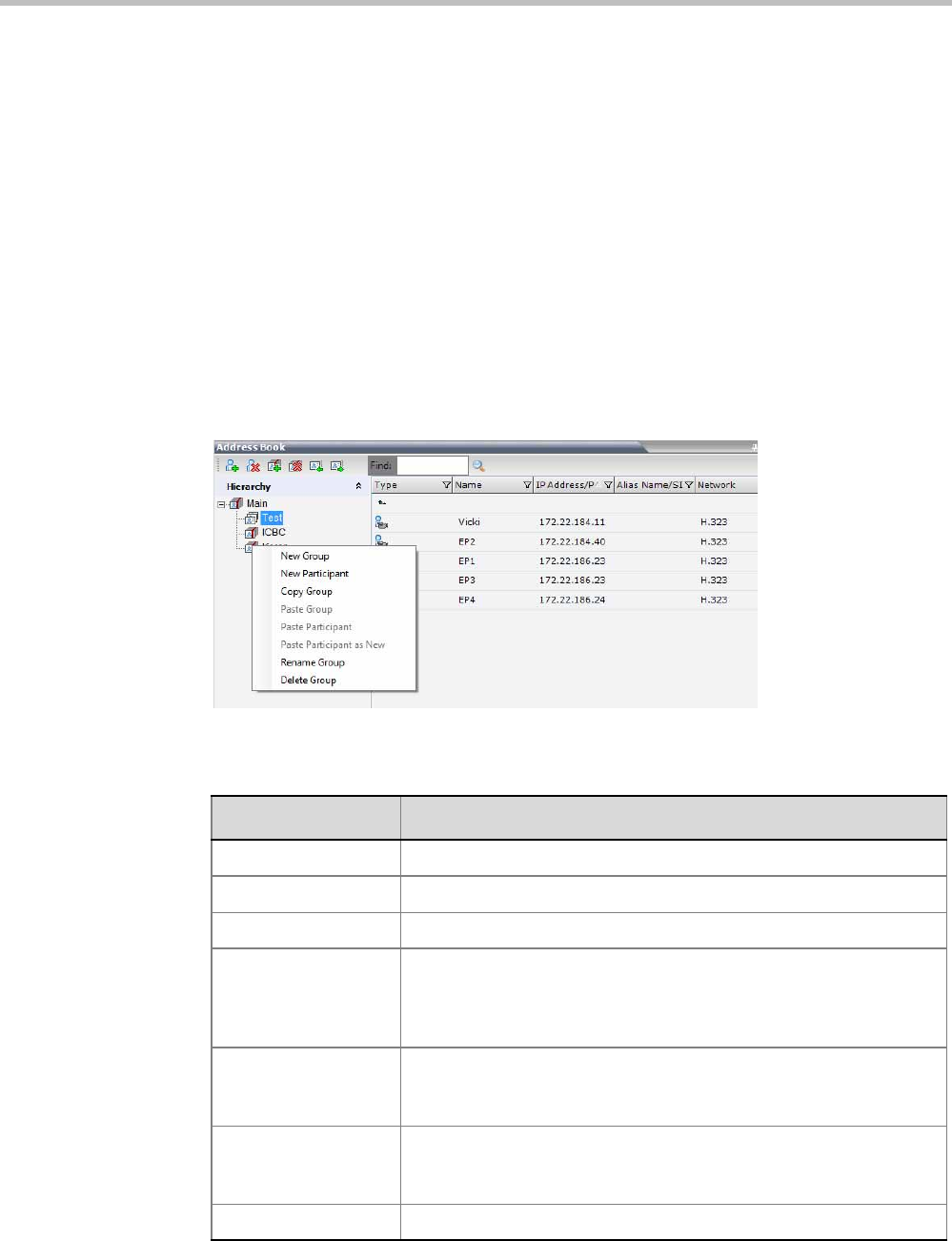
Polycom® RealPresence Collaboration ServerVirtual Edition Administrator’s Guide
8-6 Polycom, Inc.
Participant Groups
A group is a predefined collection of participants. A group provides an easy way to manage
clusters of participants that are in the same organizational structure and to connect a
combination of endpoints to a conference. For example, if you frequently conduct
conferences with the marketing department, you can create a group called “Marketing
Team” that contains the endpoints of all members of the marketing team.
Groups can contain participants and sub-groups. You can define up to ten levels in the
“Main” group.
Managing Groups in the Address Book
To manage the groups in the Address Book:
1In the Address Book Navigation pane, right-click the group you want to manage.
The Groups menu is displayed.
2Select one of the following actions:
Table 8-2 Groups Drop-down Menu Actions
Action Description
New Group Creates a new group within the current group.
New Participant Adds a new participant within the current group.
Copy Group Copies the current group to be pasted as an additional group.
Paste Group Places the copied group into the current group. The group name of
the copied group is defined with “Copy” at the end of the group name.
This action is only available after a Copy Group action has been
implemented.
Paste Participant Places the copied participant into the current selected group. This
action is available after a Copy or Cut action was activated when
selecting a single participant or multiple participants.
Paste Participant as
New
Pastes as a new participant into the selected group. This paste action
adds “Copy” at the end of the participant name. This action is only
available after a Copy action was activated for a single participant.
Rename Group Renames the group name.

Chapter 8-Address Book
Polycom, Inc. 8-7
Additionally, you can drag a group from one location in the Address Book to another
location, moving the group and all its members, including sub-groups, to its new location
using the drag-and-drop operation. Moving a group to a new location can be done in the
navigation pane or the list pane.
To drag a group from a location in the address book to another location:
1Select the group you want to move.
2Click and hold the left mouse button and drag the selection to the new location. The
new location can be either the “Main” root level or another group level.
The group and all its members (participants and groups) are moved to the new address
book location.
Managing the Address Book
Guidelines
• The multi-level Address Book can only be used in a local configuration on the
Collaboration Server. The hierarchical structure cannot be implemented with the Global
Address Book (GAB).
• Up to ten levels can be defined in the hierarchical structure of the Address Book.
• The default name of the root level is “Main”. The “Main” root level cannot be deleted
but the root level name can be modified.
• Address Book names support multilingual characters.
• Participants in the Address Book can be copied to multiple groups. However, only one
participant exists in the Address Book. Groups that contain the same participants refer to
the same definition of the participant entity.
Adding a Participant to the Address Book
Adding participants to the Address Book can be performed by the following methods:
• Directly in the Address Book.
• Moving or saving a participant from an ongoing conference to the Address Book.
When adding dial-out participants to the ongoing conference, the system automatically
dials out to the participants using the Network Service
defined for the connection in the
participant properties.
Delete Group Deletes the group and all of its members. This action displays a
message requesting confirmation to delete the group and all
members connected with the group.
Table 8-2 Groups Drop-down Menu Actions (Continued)
Action Description
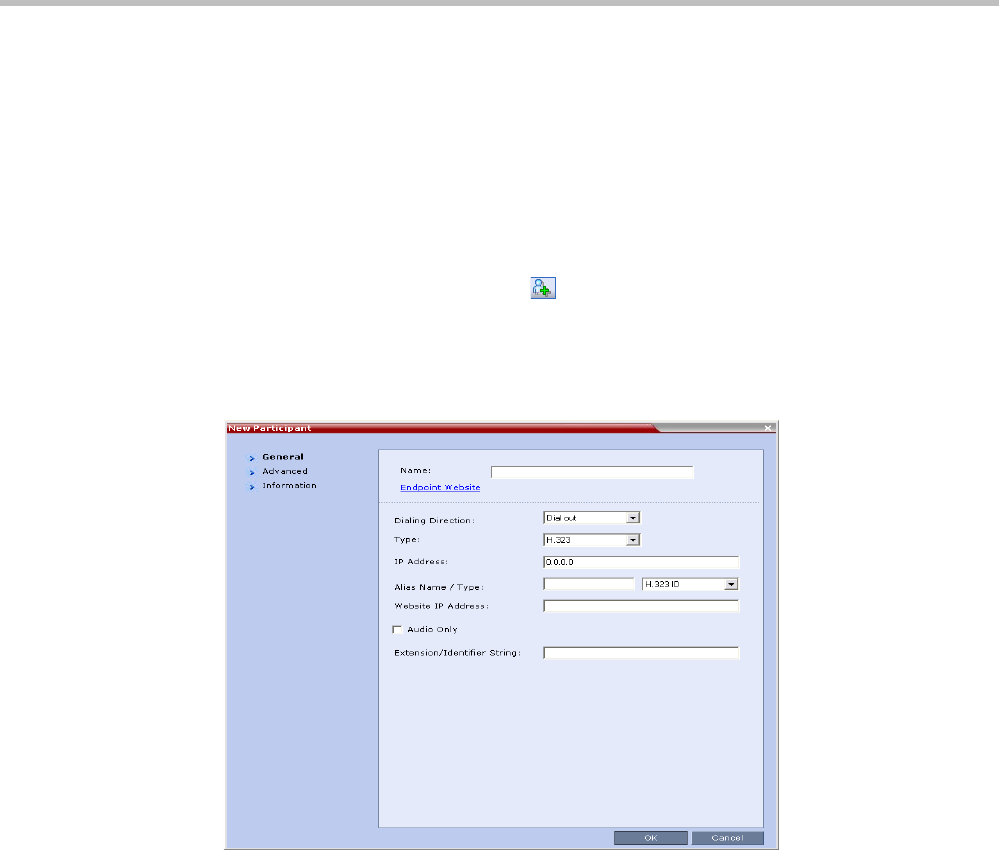
Polycom® RealPresence Collaboration ServerVirtual Edition Administrator’s Guide
8-8 Polycom, Inc.
Adding a New participant to the Address Book Directly
You can add a new participant to the “Main” group or to a group in the Address Book.
Additionally, you can add a participant from a new conference, ongoing conference, or
Conference Template.
To add a new participant to the Address Book:
1In the Address Book - Navigation pane, select the group to where you want to add the
new participant.
2Click the New Participant button ( ) or right-click the group to where you want to
add the participant and select the New Participant option.
—Alternatively, click anywhere in the List pane and select the New Participant
option.
The New Participant - General dialog box opens.

Chapter 8-Address Book
Polycom, Inc. 8-9
3Define the following fields:
Table 8-3 New Participant – General Properties
Field Description
Name Enter the name of the participant or the endpoint as it will be
displayed in the Collaboration Server Web Client.
The Name field can be modified using Unicode encoding.
•
English text uses ASCII encoding and can contain the most
characters (length varies according to the field).
•European and Latin text length is approximately half the length of
the maximum.
•Asian text length is approximately one third of the length of the
maximum.
Maximum field length in ASCII is 80 characters.
The maximum length of text fields varies according to the mixture of
character sets used (Unicode and ASCII).
This field may not be left blank. Duplicate participant names, comma,
and semi-colon characters may not be used in this field.
This name can also become the endpoint name that is displayed in
the video layout. For more details about endpoint (site) names, see
the Polycom® RealPresence Collaboration Server Virtual Edition
Getting Started Guide, "Audio and Visual Indications (AVC CP
Conferencing)” on page 3-36”.
Note: This field is displayed in all tabs.
Endpoint Website Click the Endpoint Website hyperlink to connect to the internal
website of the participant’s endpoint. It enables you to perform
administrative, configuration and troubleshooting activities on the
endpoint.
The connection is available only if the IP address of the endpoint’s
internal site is defined in the Website IP Address field.
Dialing Direction Select the dialing direction:
•Dial-in – The participant dials in to the conference. This field
applies to IP participants only.
•Dial-out – The MCU dials out to the participant.
Type The network communication protocol used by the endpoint to connect
to the conference: H.323 or SIP.
The fields in the dialog box change according to the selected network
type.
IP Address Enter the IP address of the participant’s endpoint.
•For H.323 participant define either the endpoint IP address or
alias.
•For SIP participant define either the endpoint IP address or the
SIP address.
For Collaboration Servers registered to a gatekeeper, the
Collaboration Server can be configured to dial and receive calls to
and from H.323 endpoints using the IP address in the event that the
Gatekeeper is not functioning.

Polycom® RealPresence Collaboration ServerVirtual Edition Administrator’s Guide
8-10 Polycom, Inc.
Alias Name/Type
(H.323 Only)
If you are using the endpoint’s alias and not the IP address, first
select the type of alias and then enter the endpoint’s alias:
•H.323 ID (alphanumeric ID)
•E.164 (digits 0-9, * and #)
•Email ID (email address format,
e.g. abc@example.com)
•Participant Number (digits 0-9, * and #)
Notes:
•Although all types are supported, the type of alias is dependent on
the gatekeeper’s capabilities. The most commonly supported alias
types are H.323 ID and E.164.
•This field is used to enter the Entry Queue ID, target Conference
ID and Conference Password when defining a cascaded link.
•Use of the E.164 Number is dependent on the setting of the
REMOVE_IP_IF_NUMBER_EXISTS System Flag. For more
information see "Substituting E.164 Number in Dial String” on
page 8-13.
SIP Address/Type
(SIP Only)
Select the format in which the SIP address is written:
•SIP URI - Uses the format of an E-mail address, typically
containing a user name and a host name: sip:[user]@[host]. For
example, sip:dan@polycom.com.
Note: If the SIP Address field contains an IPv6 address, it must be
surrounded by square brackets, for example, [::1].
•TEL URI - Used when the endpoint does not specify the domain
that should interpret a telephone number that has been input by
the user. Rather, each domain through which the request passes
would be given that opportunity.
For example, a user in an airport might log in and send requests
through an outbound proxy in the airport. If the users enters “411”
(this is the phone number for local directory assistance in the United
States), this number needs to be interpreted and processed by the
outbound proxy in the airport, and not by the user's home domain. In
this case, tel: 411 is the correct choice.
Endpoint Website IP
Address
Enter the IP address of the endpoint’s internal site to enable
connection to it for management and configuration purposes.
This field is automatically completed the first time that the endpoint
connects to the Collaboration Server. If the field is blank it can be
manually completed by the system administrator. The field can be
modified while the endpoint is connected
Audio Only Select this check box to define the participant as a voice participant,
with no video capabilities.
Table 8-3 New Participant – General Properties (Continued)
Field Description

Chapter 8-Address Book
Polycom, Inc. 8-11
4Usually, additional definitions are not required and you can use the system defaults for
the remaining parameters. In such a case, click OK.
To modify the default settings for advanced parameters, click the Advanced tab.
Extension/Identifier
String
Dial-out participants that connect to an external device such as
Cascaded Links or Recording Links may be required to enter a
conference password or an identifying string to connect. Enter the
required string as follows:
[p]…[p][string]
For example: pp4566#
p - optional - indicates a pause of one second before sending the
DTMF string. Enter several concatenated [p]s to increase the delay
before sending the string. The required delay depends on the
configuration of the external device or conference IVR system.
String - enter the required string using the digits 0-9 and the
characters * and #. The maximum number of characters that can be
entered is identical to the H.323 alias length.
If the information required to access the device/conference is
composed of several strings, for example, the conference ID and the
conference password, this information can be entered as one string,
where pauses [p] are added between the strings for the required
delays, as follows:
[p]…[p][string][p]…[p] [string]...
For example: p23pp*34p4566#
Extension/Identifier
String (continued)
The Collaboration Server automatically sends this information upon
connection to the destination device/conference. The information is
sent by the Collaboration Server as DTMF code to the destination
device/conference, simulating the standard IVR procedure.
Table 8-3 New Participant – General Properties (Continued)
Field Description
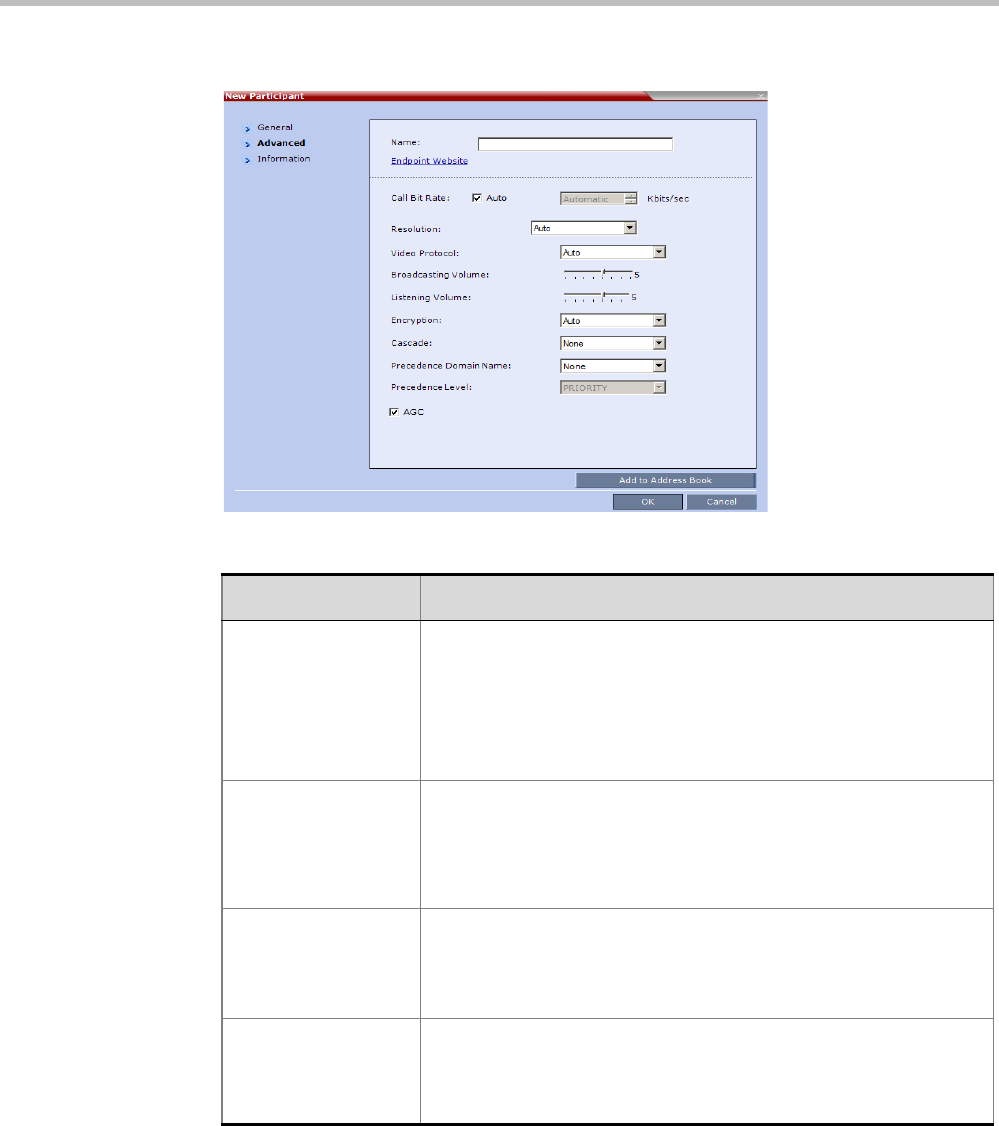
Polycom® RealPresence Collaboration ServerVirtual Edition Administrator’s Guide
8-12 Polycom, Inc.
5Define the following Advanced parameters:
Table 8-4 New Participant – Advanced Properties
Field Description
Video Bit Rate / Auto The Auto check box is automatically selected to use the Line Rate
defined for the conference.
Note: This check box cannot be cleared when defining a new
participant during an ongoing conference.
To specify the video rate for the endpoint, clear this check box and
then select the required video rate.
Video Protocol Select the video compression standard that will be forced by the MCU
on the endpoint when connecting to the conference: H.261, H.263,
H.264 or RTV.
Select Auto to let the MCU select the video protocol according to the
endpoint’s capabilities.
Resolution The Auto check box is automatically selected to use the Resolution
defined for the conference.
To specify the Resolution for the participant, select the required
resolution from the drop-down menu.
Encryption Select whether the endpoint uses encryption for its connection to the
conference.
Auto (default setting) indicates that the endpoint will connect
according to the conference encryption setting.

Chapter 8-Address Book
Polycom, Inc. 8-13
6To add general information about the participant, such as e-mail, company name, and
so on, click the Information tab and type the necessary details in the Info 1-4 fields.
Text in the info fields can be added in Unicode format (length: 31 characters).
7Click OK.
The new participant is added to the selected group in the address book.
Substituting E.164 Number in Dial String
Between the time a conference is scheduled and when it becomes active, the IP of an
endpoint may change, especially in an environment that uses DHCP. The MCU can be set to
ignore the IP address of a participant when the conference starts. Instead, the alternative
E.164 number will be used.
A new flag, REMOVE_IP_IF_NUMBER_EXISTS, has been added to control this option. This
flag must be manually added to change its value. The values of this flag are:
•YES (default) - The IP address of an endpoint will be ignored.
•NO - The IP address of an endpoint will be used.
Guidelines
• When this feature is enabled, the IP address field of participants in scheduled
conferences and conference templates will be empty.
• In order for the MCU to ignore the IP of H.323 participants, the following requirements
must be met:
—A gatekeeper must be defined.
—The alias of the participant must be defined.
—The alias type must be defined (not set to None).
• If an H.323 gatekeeper is defined but is not connected, the MCU will fail to connect to
H.323 dial-out participants.
Cascaded If this participant is used as a link between conferences select:
•Slave, if the participant is defined in a conference running on a
Slave MCU.
•Master, if the participant is defined in a conference running on the
Master MCU.
It enables the connection of one conference directly to another
conference using an H.323 connection only. The conferences can run
on the same MCU or different MCU’s. For more information, see
"Basic Cascading using IP Cascaded Link” on page 5-3.
Precedence Domain
Name
(Dial-out SIP Only)
Not supported with RealPresence Collaboration Server Virtual
Edition.
Precedence Level
(Dial-out SIP Only)
Not supported with RealPresence Collaboration Server Virtual
Edition.
AGC The Audio Gain Control (AGC) protocol that reduces noises is
enabled by default for the participants.
Clear this check box to disable the AGC feature.
Table 8-4 New Participant – Advanced Properties (Continued)
Field Description
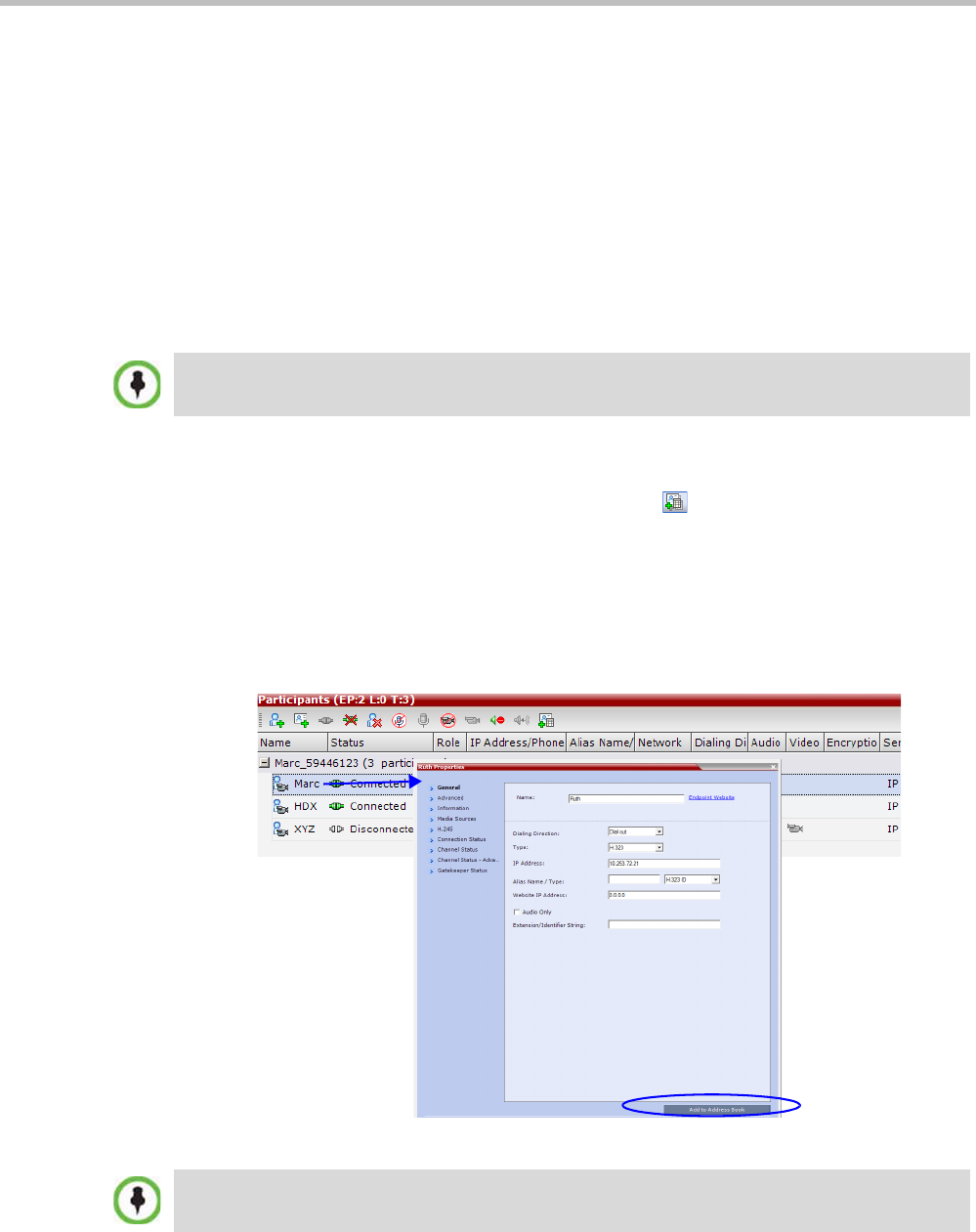
Polycom® RealPresence Collaboration ServerVirtual Edition Administrator’s Guide
8-14 Polycom, Inc.
• In order for the MCU to ignore the IP of SIP participants, the following requirements
must be met:
—A SIP proxy must be defined.
—The SIP address must be defined.
• If a SIP proxy is defined but is not connected, the MCU will fail to connect to SIP dial-
out participants.
Adding a Participant from an Ongoing Conference to the Address Book
You can add a participant to the Address Book directly from an ongoing conference.
To add a participant from the conference to the Address Book:
1During an ongoing conference, select the participant in the Participant pane and either
click the Add Participant to Address Book button ( ) or right-click and select Add
Participant to Address Book.
The participant is added to the Address Book.
Alternatively, you could:
aDouble-click the participant’s icon or right-click the participant icon and click
Participant Properties.
The Participant Properties window opens.
bClick the Add to Address Book button.
When adding a participant to the address book from a new conference, Participants list of an
ongoing conference or Conference Template, the participant is always added to the “Main” group.
If the participant name is already listed in the All Participants list, an error message is displayed. In
such a case, change the name of the participant before adding the participant to the address book.
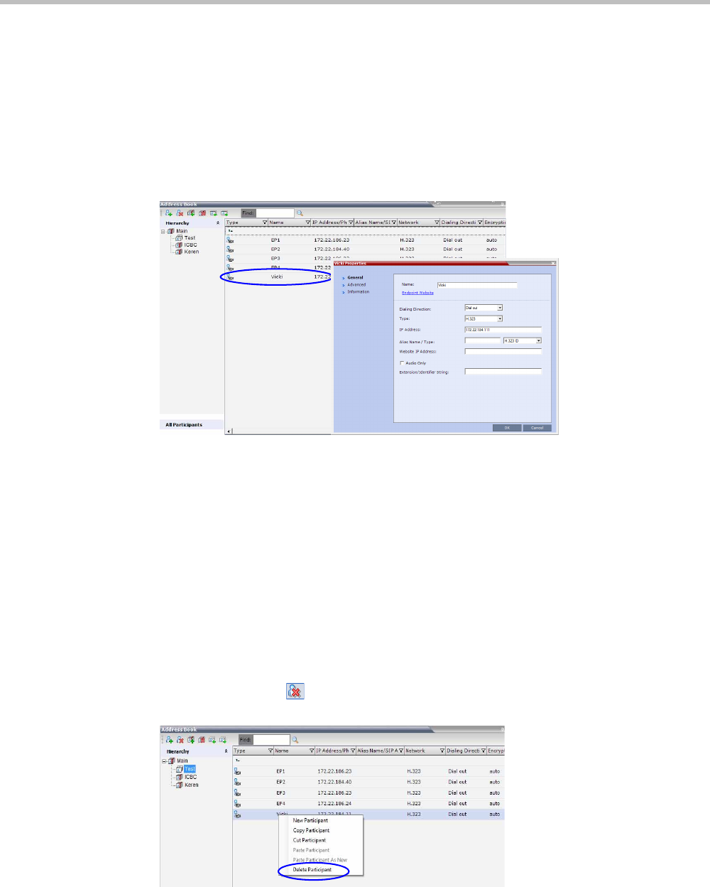
Chapter 8-Address Book
Polycom, Inc. 8-15
Modifying Participants in the Address Book
When required, you can modify the participant’s properties.
To modify participant properties in the Address Book:
1In the Address Book - Navigation pane, select the group to where the participant to
modify is listed.
2In the Address Book - List pane, double-click the participant’s icon.
The Participant’s Properties window is displayed.
3Modify the necessary properties in the window, such as dialing direction,
communication protocol type, and so on. You can modify any property in any of the
three tabs: General, Advanced and Info.
4Click OK.
The changes to the participant’s properties are updated.
Deleting Participants from the Address Book
To delete participants from the Address Book:
1In the Address Book - Navigation pane, select the group where the participant to delete is
listed.
2In the Address Book - List pane, either select the participant to delete and then click the
Delete Participant ( ) button, or right-click the participant icon and then click the
Delete Participant option.
3A confirmation message is displayed depending on the participant’s assignment to
groups in the address book:
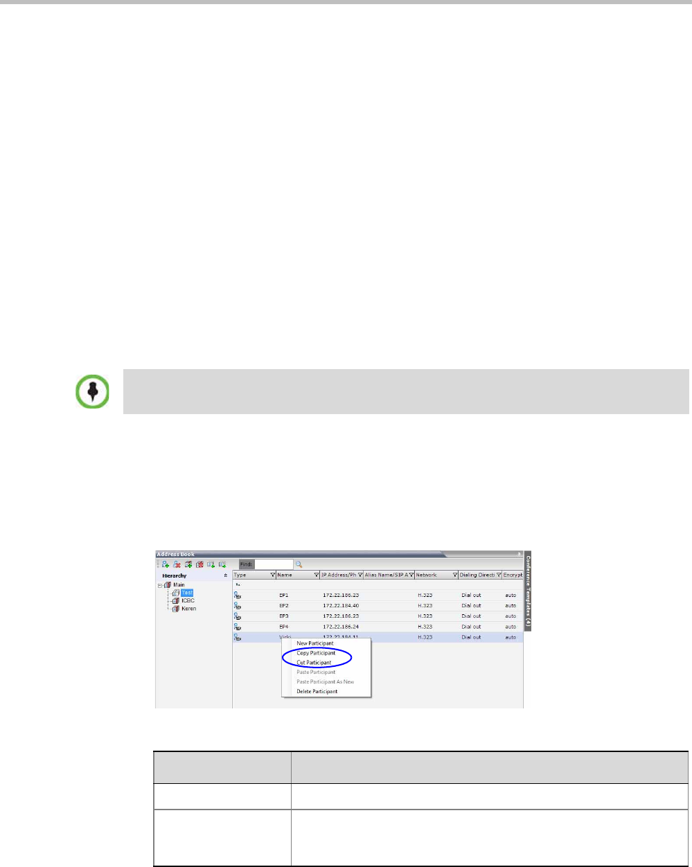
Polycom® RealPresence Collaboration ServerVirtual Edition Administrator’s Guide
8-16 Polycom, Inc.
aWhen the participant belongs to only one group: click Yes to permanently delete
the participant from the address book.
bWhen the participant belongs to multiple groups, a message is displayed
requesting whether to delete the participant from the Address Book or from the
current selected group. Select:
•Current group to delete the participant from the selected group
•Address Book to permanently delete the participant from the address book
(all groups).
Click OK to perform the delete operation or Cancel to exit the delete operation.
Copying or Moving a Participant
You can copy or move a participant from one group to another group using the Copy, Cut,
and Paste options. A participant can belong to multiple groups. However, there is only one
entity per participant. Groups that contain the same participants refer to the same definition
of the participant entity. Alternatively, you can drag a participant from one location in the
Address Book to another location, moving the participant to its new location using the drag-
and-drop operation.
To copy or move a participant to another group:
1In the Address Book - Navigation pane, select the group from where to copy the
participant.
2In the Address Book - List pane, select the participant you want to copy.
3Right-click the selected participant and select one of the following functions from the
drop-down menu:
The cut and copy actions are not available when selecting multiple participants.
Table 8-5 Copy/Cut Functions
Function Description
Copy Participant Copies the participant to be pasted into an additional group.
Cut Participant Moves the participant from the current group to a different group.
Alternatively, you can move a participant to another location by
dragging the participant to the new location.
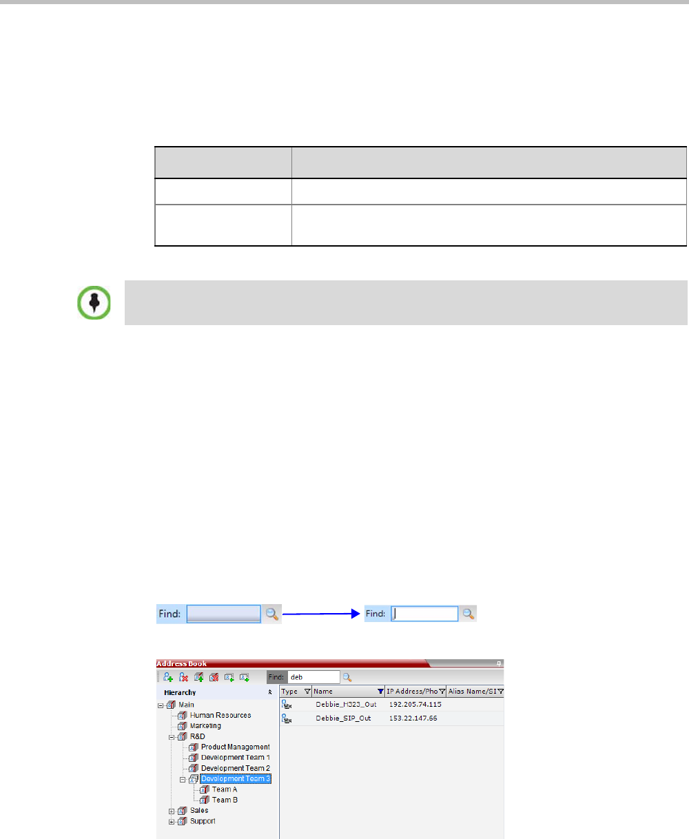
Chapter 8-Address Book
Polycom, Inc. 8-17
4In the Address Book navigation pane, navigate and select the group in which you want to
paste the participant.
5Right-click the selected group and click one of the following Paste functions from the
drop-down menu:
To drag a participant from an address book group to another group:
1Select the participant or participants you want to move.
2Click and hold the left mouse button and drag the selection to the new group.
The participants are moved to the new address book group.
Searching the Address Book
You can search the Address Book for a participant’s name or a group name only on the
currently selected group/level.
To search for participants or groups in the current selected level:
1In the Address Book Navigation pane, select the group/level within to run the search.
2In the Address Book toolbar, activate the search option by clicking the Find field.
The field clears and a cursor appears indicating that the field is active.
3Type all or part of the participant’s name or group name and click the search button.
The closest matching participant entries are displayed and the Active Filter indicator
turns on.
Table 8-6 Paste functions
Function Description
Paste Participant Creates a link to the participant entity in the pasted location.
Paste Participant as
New
Pastes as a new participant into the selected group. This paste action
adds “Copy” to the end of the participant name.
The Paste functions are only available after a Copy or Cut action has been implemented.
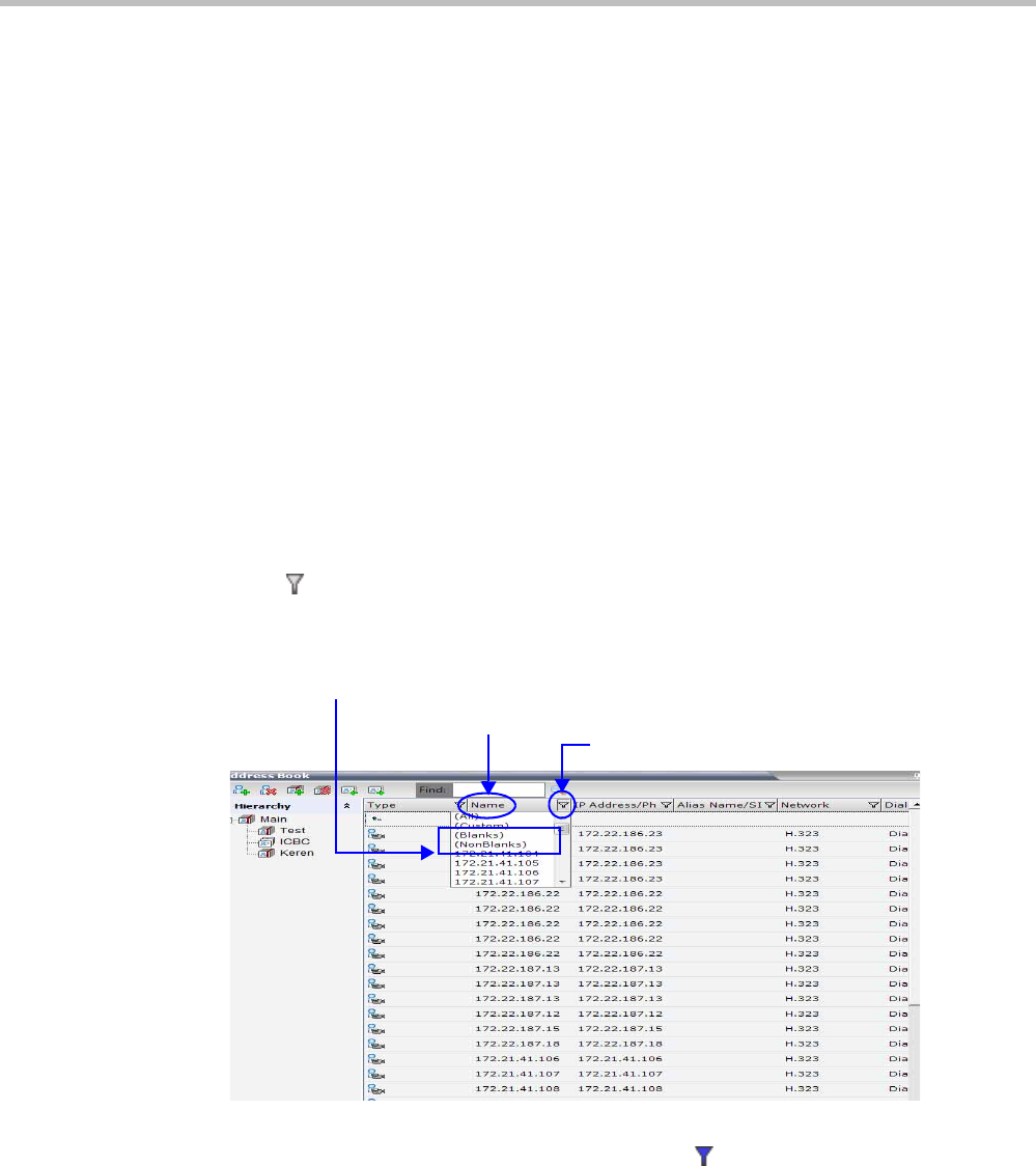
Polycom® RealPresence Collaboration ServerVirtual Edition Administrator’s Guide
8-18 Polycom, Inc.
Filtering the Address Book
The entries in an address book group can be filtered to display only the entries (participants
or groups) that meet criteria that you specify and hides entries that you do not want
displayed. It enables you to select and work with a subset of Address Book entries.
You can filter by more than one column, by adding additional filters (columns).
The filter applies to the displayed group. If All Participants option is selected, it applies to all
the listed participants.
Filtering can be done using:
• A predefined pattern
• Customized pattern
When you use the Find dialog box to search filtered data, only the data that is displayed is
searched; data that is not displayed is not searched. To search all the data, clear all filters.
Filtering Address Book Data Using a Predefined Pattern
To filter the data in an address book group:
1In the Address Book - Navigation pane, select the group to filter.
2In the Address Book - List pane, in the column that you want to use for filtering, click the
filter ( ) button.
A drop-down menu is displayed containing all the matching patterns that can be
applied to the selected field.
3Click the matching pattern to be applied.
The filtered list is displayed with a filter indicator ( ) displayed in the selected column
heading.
Filter Button
Filtering Options
Selected Column
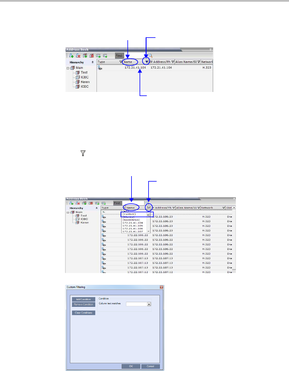
Chapter 8-Address Book
Polycom, Inc. 8-19
Example: If the user selects 172.21.41.104 as the matching pattern, the filtered group in
the Address Book is displayed as follows:
Filtering Address Book Data Using a Custom Pattern
To filter the data in an address book group:
1In the Address Book - Navigation pane, select the group to filter.
2In the Address Book - List pane, in the column that you want to use for filtering, click the
filter ( ) button.
3Select the (Custom) option from the drop-down list.
The Custom Filtering dialog box opens.
Active Filter Indicator
Selected Column
1 Entry matching “172.21.41.104” in filtered group
Filter Button
Selected Column
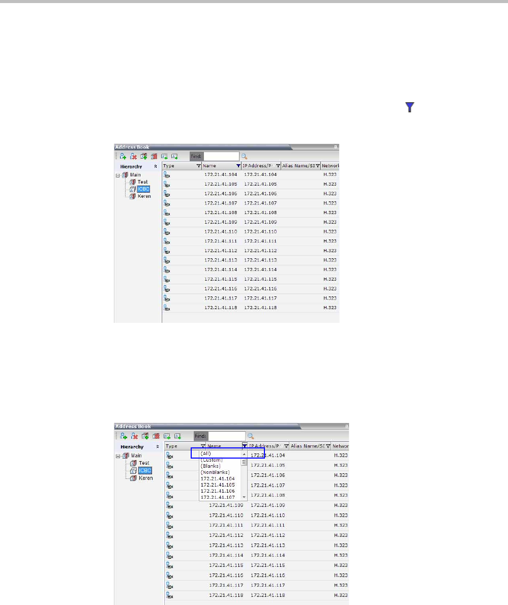
Polycom® RealPresence Collaboration ServerVirtual Edition Administrator’s Guide
8-20 Polycom, Inc.
4In the Condition - Column text matches field, enter the filtering pattern.
For example, to list only endpoints that include the numerals 41 in their name, enter 41.
5Optional. Click the Add Condition button to define additional filtering patterns to
further filter the list and fine tune your search.
To clear a filtering pattern, click the Clear Condition button.
The filtered list is displayed with an active filter (blue) indicator ( ) displayed in the
selected column heading. For example, if the filtering pattern is 41, the participants list
includes all the endpoints that contain the numerals 41 in their name.
Clearing the Filter
To clear the filter and display all entries:
1In the filtered Address Book column heading, click the Active Filter indicator.
The pattern matching options menu is displayed.
2Click (All).
The filter is deactivated and all the group/level entries are displayed.
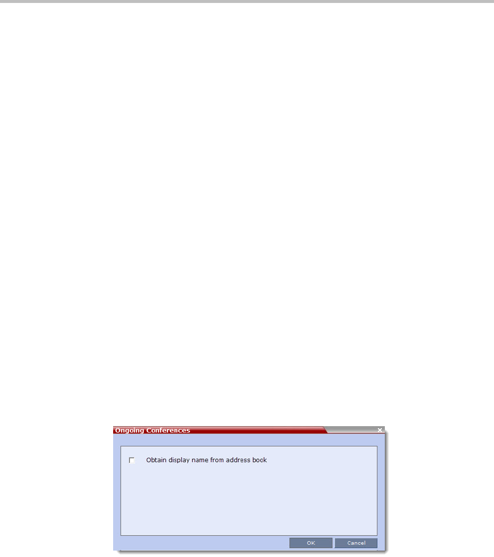
Chapter 8-Address Book
Polycom, Inc. 8-21
Obtaining the Display Name from the Address Book
The MCU can be configured to replace the name of the dial-in participant as defined in the
endpoint (site name) with the name defined in the Address Book.
In this process, the system retrieves the data (name, alias, number or IP address) of the dial-
in participant and compares it first with the conference defined dial-in participants and if
the endpoint is not found, it then searches for the endpoint with entries in the address book.
After a match is found, the system displays the participant name as defined in the address
book instead of the site name, in both the video layout and the Collaboration Server Web
Client/Manager.
The system compares the following endpoint data with the address book entries:
• For H.323 participants, the system compares the IP address, Alias, or H.323 number.
• For SIP participants, the system compares the IP address or the SIP URI.
Guidelines
•Only Users with Administrator and Operator Authorization Levels are allowed to enable
and disable the Obtain Display Name from Address Book feature.
• This feature is supported only for IPv4 participants.
Enabling and Disabling the Obtain Display Name from Address Book
Feature
The Obtain Display Name from Address Book option can be enabled for all participants
connecting to the MCU if the name of the participants are defined in the Address Book.
To enable or disable the Obtain Display Name from Address Book option:
1On the Collaboration Server main menu bar, click Setup > Customize Display Settings
> Ongoing Conferences.
The Ongoing Conferences dialog box is displayed.
2Select the Obtain display name from address book check box to enable the feature or
clear the check box to disable the feature.
3Click OK.
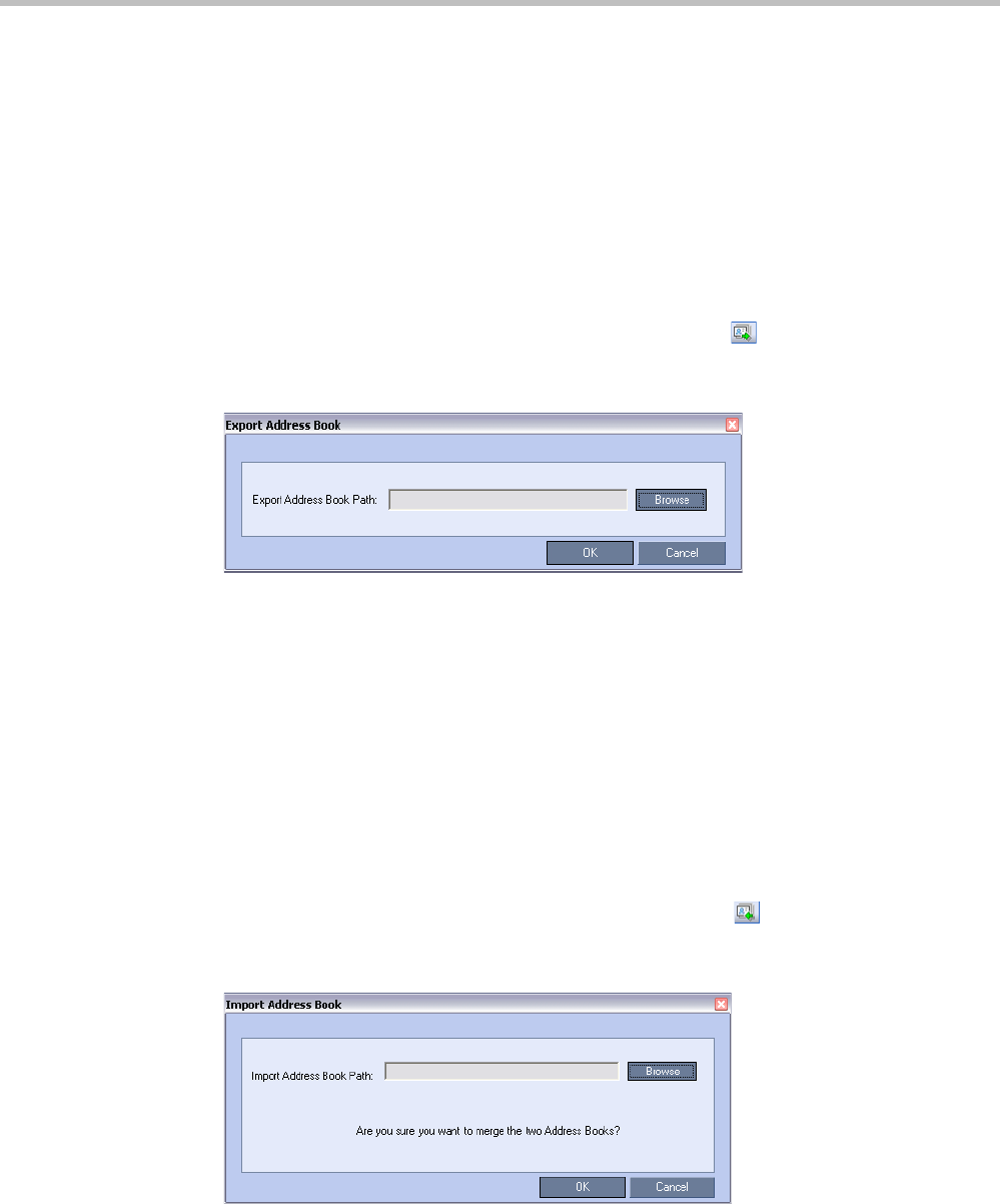
Polycom® RealPresence Collaboration ServerVirtual Edition Administrator’s Guide
8-22 Polycom, Inc.
Importing and Exporting Address Books
Address Books are proprietary Polycom data files that can only be distributed among
Collaboration Server units. The Address Books are exported in XML format, which are
editable offline. If no name is assigned to the exported Address Book, the default file name
is: EMA.DataObjects.OfflineTemplates.AddressbookContent_.xml
Exporting an Address Book
To Export an Address Book:
1In the Address Book pane, click the Export Address Book ( ) button or right-click an
empty area in the pane and click Export Address Book.
The Export Address Book dialog box is displayed.
2Enter the desired path or click the Browse button.
3In the Save Address Book dialog box, select the directory to save the file. You may also
rename the file in the File Name field.
4Click Save.
You will return to the Export File dialog box.
5Click OK.
The exported Address Book is saved in the selected folder in XML format.
Importing an Address Book
To Import and Address Book:
1In the Address Book pane, click the Import Address Book ( ) button or right-click an
empty area in the pane and then click Import Address Book.
The Import Address Book dialog box is displayed.
2Enter the path from which to import the Address Book or click the Browse button.
3In the Open dialog box navigate to the desired Address Book file (in XML format) to
import.
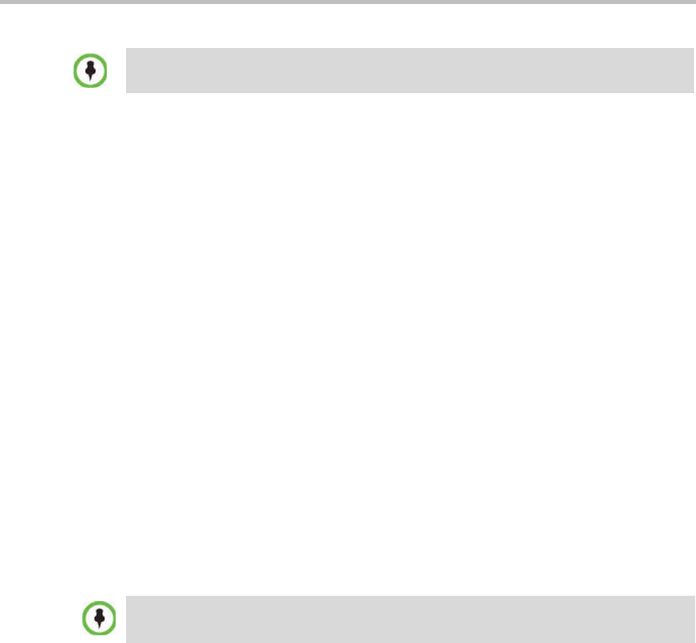
Chapter 8-Address Book
Polycom, Inc. 8-23
4Click Open.
You will return to the Import File dialog box.
5Click OK.
The Address Book is imported and a confirmation message is displayed at the end of the
process.
6Click Close.
Integrating the Global Address Book (GAB) of Polycom
RealPresence Resource Manager (XMA) or Polycom
CMA™ with the Collaboration Server
The Polycom RealPresence Resource Manager (XMA) or Polycom CMA™ application
includes a Global Address Book (GAB) with all registered endpoints. This address book can
be used by the Collaboration Server users to add participants to conferences.
Guidelines for integrating with the Global Address Book of Polycom RealPresence
Resource Manager (XMA) or Polycom CMA™:
• The Collaboration Server can use only one address book at a time. After you integrate
the Polycom RealPresence Resource Manager (XMA) or Polycom CMA with the
Polycom Collaboration Server, the XMA/CMA address book replaces the Collaboration
Server internal address book.
• The Collaboration Server uses the RealPresence Resource Manager (XMA) or Polycom
CMA address book in read-only mode. You can only add or modify XMA/CMA
address book entries from the RealPresence Resource Manager (XMA) or Polycom
CMA.
To Integrate the RealPresence Resource Manager (XMA) or Polycom CMA Global
Address Book (GAB) with the Collaboration Server:
RealPresence Resource Manager (XMA) or Polycom CMA Side
1In the RealPresence Resource Manager (XMA) or Polycom CMA application, manually
add the Polycom Collaboration Server system to the RealPresence Resource Manager
(XMA) or Polycom CMA system as directed in the PRealPresence Resource Manager
(XMA) or Polycom CMA Operations Guide.
2In the RealPresence Resource Manager (XMA) or Polycom CMA application, add a user
or use an existing user for Collaboration Server login as directed in the RealPresence
Resource Manager (XMA) or Polycom CMA Operations Guide.
Write down the User Name and Password as they will be used later to define the
Collaboration Server connection to the RealPresence Resource Manager (XMA) or
Polycom CMA Global Address Book.
When importing an Address Book, participants with exact names in the current Address Book will be
overwritten by participants defined in the imported Address Book.
The Collaboration Server acts as a proxy to all address book requests between the Collaboration
Server Web Client and the XMA/CMA. Ensure that firewall and other network settings allow the
Collaboration Server access to the XMA or CMA server.
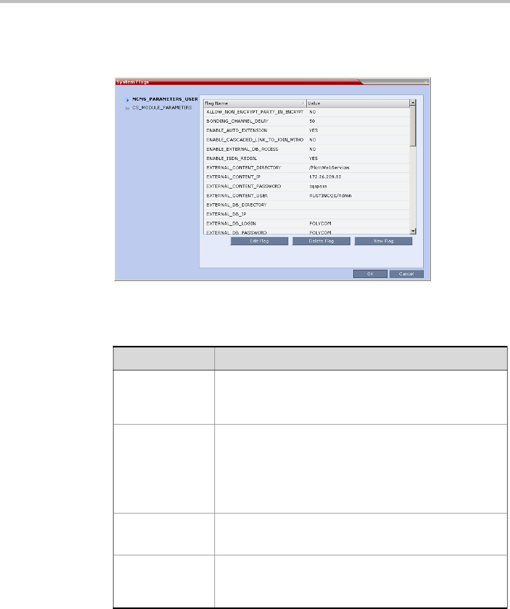
Polycom® RealPresence Collaboration ServerVirtual Edition Administrator’s Guide
8-24 Polycom, Inc.
Collaboration Server Side
1On the Collaboration Server menu, click Setup > System Configuration.
The System Flags - MCMS_PARAMETERS_USER dialog box opens.
2Modify the values of the following flags:
For more information, see "Modifying System Flags” on page 20-1.
3Click OK to complete the definitions.
When prompted, click Yes to reset the MCU and implement the changes to the system
configuration.
Table 8-7 System Flags for CMA Address Book Integration
Flag Description
EXTERNAL_CONTE
NT_DIRECTORY
The Web Server folder name. Change this name if you have changed
the default names used by the RealPresence Resource Manager
(XMA) or Polycom CMA application.
Default: /PlcmWebServices
EXTERNAL_CONTE
NT_IP
Enter the IP address of the RealPresence Resource Manager (XMA)
or Polycom CMA server. For example: 172.22.185.89.
This flag is also the trigger for replacing the internal Collaboration
Server address book with the RealPresence Resource Manager
(XMA) or Polycom CMA Global Address Book (GAB).
Leave this flag blank to disable address book integration with the
RealPresence Resource Manager (XMA) or Polycom CMA server.
EXTERNAL_CONTE
NT_PASSWORD
The password associated with the user name defined for the
Collaboration Server in the RealPresence Resource Manager (XMA)
or Polycom CMA server.
EXTERNAL_CONTE
NT_USER
The login name defined for the Collaboration Server in the
RealPresence Resource Manager (XMA) or Polycom CMA server
defined in the format:
domain name/user name.

Polycom, Inc. 9-1
9
Operator Assistance & Participant
Move
Users (operators) assistance to participants is available when:
• Participants have requested individual help (using *0 DTMF code) during the
conference.
• Participants have requested help for the conference (using 00 DTMF code) during the
conference.
• Participants have problems connecting to conferences, for example, when they enter the
wrong conference ID or password.
In addition, the user (operator) can join the ongoing conference and assist all conference
participants.
Operator assistance is available only when an Operator conference is running on the MCU.
The Operator conference offers additional conference management capabilities to the
Collaboration Server users, enabling them to attend to participants with special requirements
and acquire participant details for billing and statistics. This service is designed usually for
large conferences that require the personal touch.
Operator Conferences
An Operator conference is a special conference that enables the Collaboration Server user
acting as an operator to assist participants without disturbing the ongoing conferences and
without being heard by other conference participants. The operator can move a participant
from the Entry Queue or ongoing conference to a private, one-on-one conversation in the
Operator conference.
In attended mode, the Collaboration Server user (operator) can perform one of the following
actions:
• Participants connected to the Entry Queue who fail to enter the correct destination ID or
conference password can be moved by the user to the Operator conference for
assistance.
• After a short conversation, the operator can move the participant from the Operator
conference to the appropriate destination conference (Home conference).
• The operator can connect participants belonging to the same destination conference to
their conference simultaneously by selecting the appropriate participants and moving
them to the Home conference (interactively or using the right-click menu).
Operator conferences and participant move are supported in AVC CP Conferencing Mode only.

Polycom® RealPresence Collaboration ServerVirtual Edition Administrator’s Guide
9-2 Polycom, Inc.
• The operator can move one or several participants from an ongoing conference to the
Operator conference for a private conversation.
• The operator can move participants between ongoing Continuous Presence
conferences.
Operator Conference Guidelines
•An Operator conference can only run in Continuous Presence mode.
•Operator conference is defined in the Conference Profile. When enabled in Conference
Profile, High Definition Video Switching option is disabled.
•An Operator conference can only be created by a User with Operator or Administrator
Authorization level.
•Operator conference name is derived from the User Login Name and it cannot be
modified.
• Only one Operator conference per User Login Name can be created.
• When created, the Operator conference must include one and only one participant - the
Operator participant.
• Only a defined dial-out participant can be added to an Operator conference as an
Operator participant
• Once running, the Collaboration Server user can add new participants or move
participants from other conferences to this conference. The maximum number of
participants in an Operator conference is the same as in standard conferences.
• Special icons are used to indicate an Operator conference in the Ongoing Conferences list
and the operator participant in the Participants list.
•An Operator conference can be saved to a Conference Template. An ongoing Operator
conference can be started from a Conference Template.
• The Operator participant cannot be deleted from the Operator conference or from any
other conference to which she/he was moved to, but it can be disconnected from the
conference.
• When deleting or terminating the Operator conference, the operator participant is
automatically disconnected from the MCU, even if participating in a conference other
than the Operator conference.
• Moving participants from/to an Operator conference follows the same guidelines as
moving participants between conferences. For move guidelines, see "Move Guidelines”
on page 9-14.
• When a participant is moved from the Entry Queue to the Operator conference, the option
to move back to the source (Home) conference is disabled as the Entry Queue is not
considered as a source conference.
• The conference chairperson cannot be moved to the Operator conference following the
individual help request if the Auto Terminate When Chairperson Exits option is enabled,
to prevent the conference from automatically ending prematurely. In such a case, the
assistance request is treated by the system as a conference assistance request, and the
operator can join the conference.
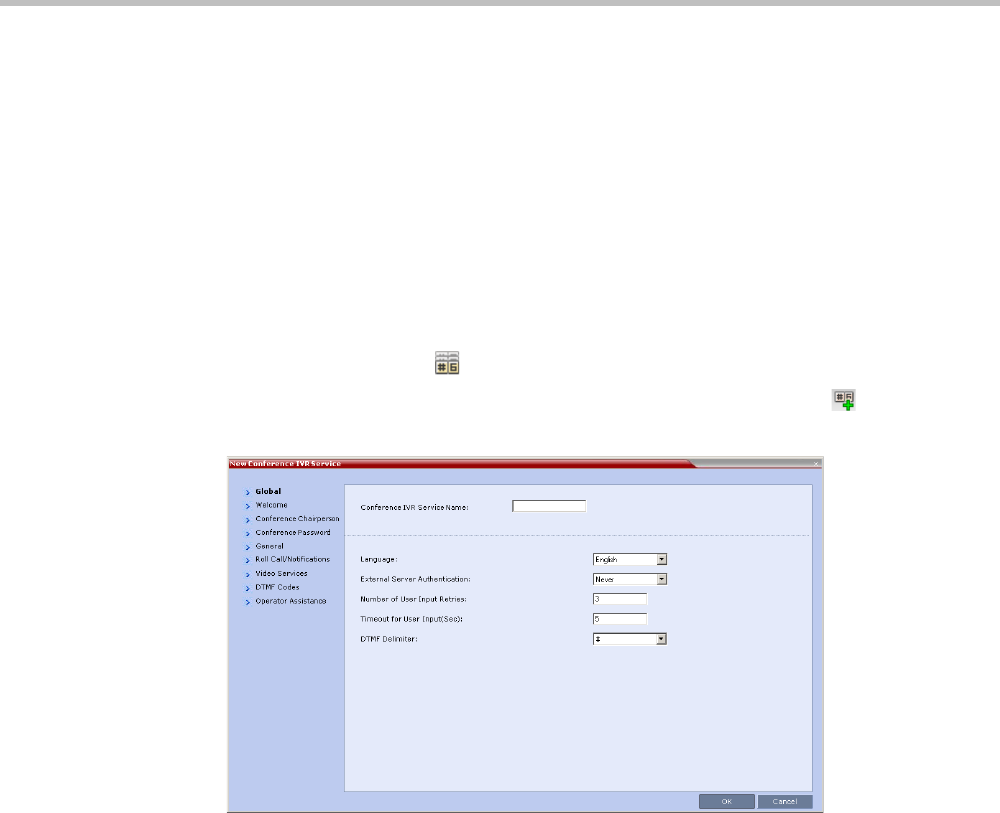
Chapter 9-Operator Assistance & Participant Move
Polycom, Inc. 9-3
Defining the Components Enabling Operator Assistance
To enable operator assistance for conferences, the following conferencing entities must be
adjusted or created:
• IVR Service (Entry Queue and Conference) in which Operator Assistance options are
enabled.
• A Conference Profile with the Operator Conference option enabled.
• An active Operator conference with a connected Operator participant.
Defining a Conference IVR Service with Operator Assistance Options
In the RealPresence Collaboration Server Management pane, expand the Rarely Used list and
click the IVR Services () entry.
1On the IVR Services toolbar, click the New Conference IVR Service () button.
The New Conference IVR Service - Global dialog box opens.
2Enter the Conference IVR Service Name.
3Define the Conference IVR Service - Global parameters. For more information, see
Table 16-3, “Conference IVR Service Properties - Global Parameters,” on page 16-7.
4Click the Welcome tab.
The New Conference IVR Service - Welcome dialog box opens.
5Define the system behavior when the participant enters the Conference IVR queue. For
more information, see "Defining a New Conference IVR Service” on page 16-6.
6Click the Conference Chairperson tab.
The New Conference IVR Service - Conference Chairperson dialog box opens.
7If required, enable the chairperson functionality and select the various voice messages
and options for the chairperson connection. For more information, see Table 16-4, “New
Conference IVR Service Properties - Conference Chairperson Options and Messages,” on
page 16-9.
8Click the Conference Password tab.
The New Conference IVR Service - Conference Password dialog box opens.
9If required, enable the request for conference password before moving the participant
from the conference IVR queue to the conference and set the MCU behavior for
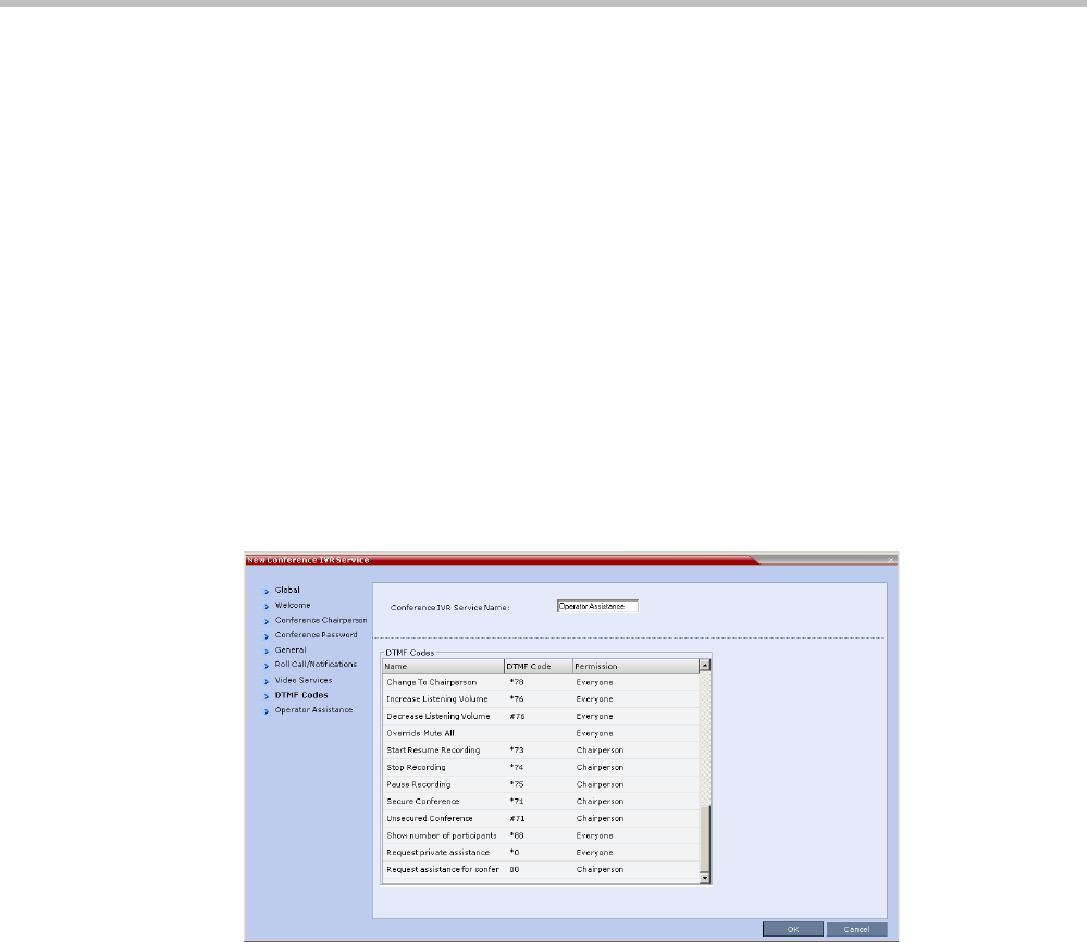
Polycom® RealPresence Collaboration ServerVirtual Edition Administrator’s Guide
9-4 Polycom, Inc.
password request for Dial-in and Dial-out participant connections. For more
information, see Table 16-5, “New Conference IVR Service Properties - Conference Password
Parameters,” on page 16-10.
10 Select the various audio messages that will be played in each case. For more
information, see Table 16-5, “New Conference IVR Service Properties - Conference Password
Parameters,” on page 16-10.
11 Click the General tab.
The New Conference IVR Service - General dialog box opens.
12 Select the messages that will be played during the conference. For more information,
see Table 16-6, “Conference IVR Service Properties - General Voice Messages,” on page 16-11.
13 Click the Video Services tab.
The New Conference IVR Service - Video Services dialog box opens.
14 Define the Video Services parameters. For more information, see Table 16-8, “New
Conference IVR Service Properties - Video Services Parameters,” on page 16-15.
15 Click the DTMF Codes tab.
The New Conference IVR Service - DTMF Codes dialog box opens.
The default DTMF codes for the various functions that can be performed during the
conference by all participants or by the chairperson are listed. For the full list of the
available DTMF codes, see Table 16-9, “New Conference IVR Service Properties - DTMF
Codes,” on page 16-16.
16 If required, modify the default DTMF codes and the permissions for various operations
including Operator Assistance options:
—*0 for individual help - the participant requested help for himself or herself. In such
a case, the participant requesting help is moved to the Operator conference for one-
on-one conversation. By default, all participants can use this code.
—00 for conference help - the conference chairperson (default) can request help for
the conference. In such a case, the operator joins the conference.
17 Click the Operator Assistance tab.
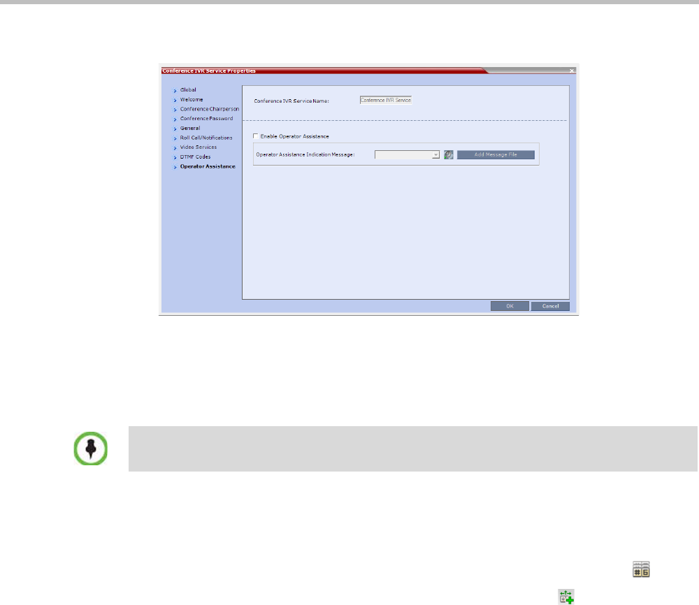
Chapter 9-Operator Assistance & Participant Move
Polycom, Inc. 9-5
The Operator Assistance dialog box opens.
18 Select Enable Operator Assistance to enable operator assistance when the participant
requires or requests help during the connection process to the conference or during the
conference.
19 In the Operator Assistance Indication Message field, select the audio message to be played
when the participant requests or is waiting for the operator’s assistance.
20 Click OK to complete the IVR Service definition.
The new Conference IVR Service is added to the IVR Services list.
Defining an Entry Queue IVR Service with Operator Assistance Options
1In the RealPresence Collaboration Server Management pane, click IVR Services ().
2In the IVR Services list, click the New Entry Queue IVR Service () button.
The New Entry Queue IVR Service - Global dialog box opens.
3Define the Entry Queue Service Name.
4Define the Entry Queue IVR Service Global parameters. For more information, see
Table 16-10, “Entry Queue IVR Service Properties - Global Parameters,” on page 16-19.
5Click the Welcome tab.
The New Entry Queue IVR Service - Welcome dialog box opens.
6Define the system behavior when the participant enters the Entry Queue. This dialog
box contains options that are identical to those in the Conference IVR Service - Welcome
Message dialog box.
7Click the Conference ID tab.
The New Entry Queue IVR Service - Conference ID dialog box opens.
8Select the required voice messages. For more information, see Table 16-11, “Entry Queue
IVR Service Properties - Conference ID,” on page 16-21.
If the audio file was not uploaded prior to the definition of the IVR Service or if you want to add new
audio files, click Add Message File to upload the appropriate audio file to the Collaboration Server.
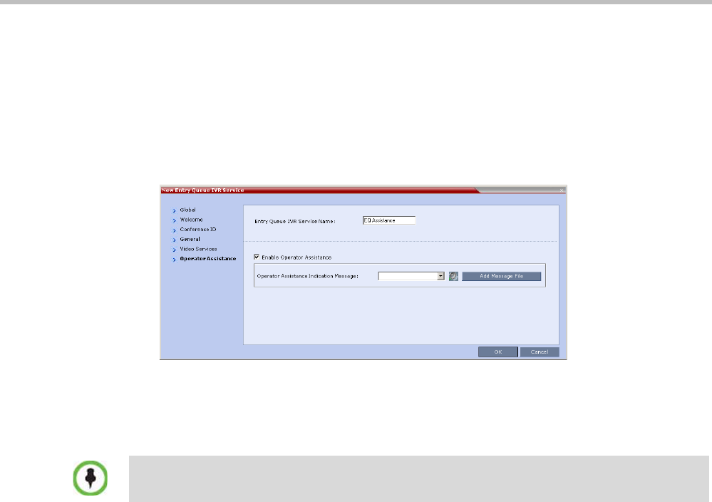
Polycom® RealPresence Collaboration ServerVirtual Edition Administrator’s Guide
9-6 Polycom, Inc.
9Click the Video Services tab.
The New Entry Queue IVR Service - Video Services dialog box opens.
10 In the Video Welcome Slide list, select the video slide that will be displayed to
participants connecting to the Entry Queue. The slide list includes the video slides that
were previously uploaded to the MCU memory.
11 Click the Operator Assistance tab.
The Operator Assistance dialog box opens.
12 Select Enable Operator Assistance to enable operator assistance when the participant
requires or requests help during the connection process.
13 In the Operator Assistance Indication Message field, select the audio message to be played
when the participant requests or is waiting for operator’s assistance.
14 Click OK to complete the Entry Queue IVR Service definition.
The new Entry Queue IVR Service is added to the IVR Services list.
Defining a Conference Profile for an Operator Conference
1In the RealPresence Collaboration Server Management pane, click Conference Profiles.
If the audio file was not uploaded prior to the definition of the IVR Service or if you want to add new
audio files, click Add Message File to upload the appropriate audio file to the Collaboration Server.
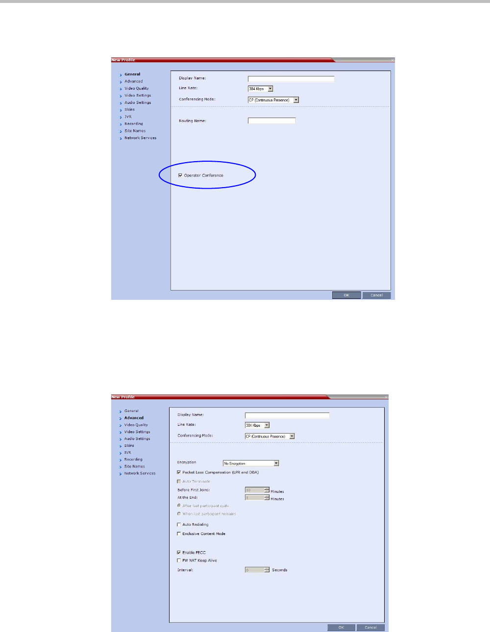
Chapter 9-Operator Assistance & Participant Move
Polycom, Inc. 9-7
2In the Conference Profiles pane, click the New Profile button.
The New Profile – General dialog box opens.
3Define the Profile name and, if required, the Profile general parameters.
For more details, see Table 2-10, “New AVC CP Profile - General Parameters,” on
page 2-21.
4Click the Operator Conference check box.
5Click the Advanced tab.
The New Profile – Advanced dialog box opens.
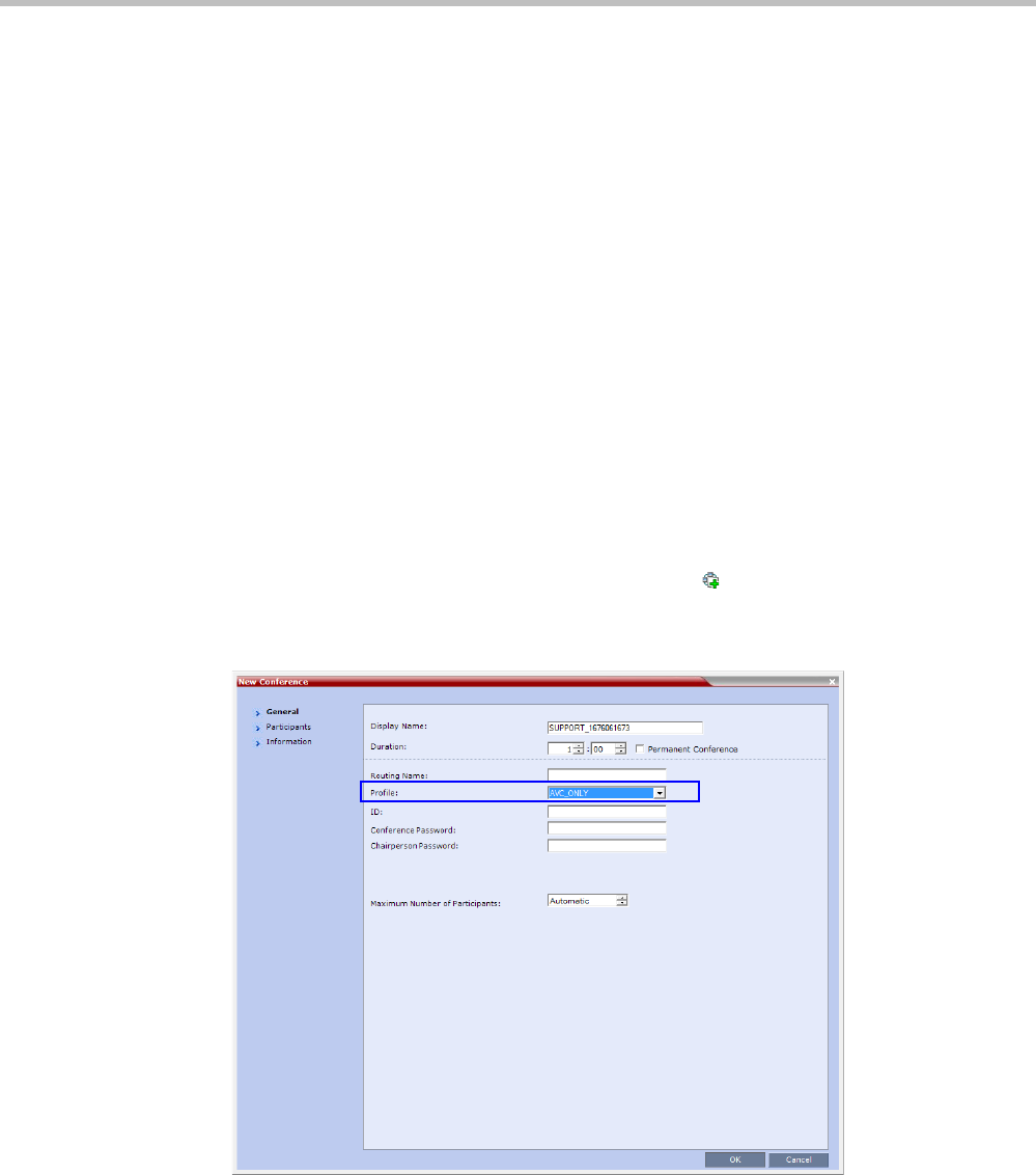
Polycom® RealPresence Collaboration ServerVirtual Edition Administrator’s Guide
9-8 Polycom, Inc.
6Define the Profile Advanced parameters.
Note that when Operator Conference is selected, the Auto Terminate selection is
automatically cleared and disabled and the Operator conference cannot automatically
end unless it is terminated by the Collaboration Server User.
7Click the Video Quality tab.
The New Profile – Video Quality dialog box opens.
8Define the Video Quality parameters.
9Click the Video Settings tab.
The New Profile - Video Settings dialog box opens.
10 Define the video display mode and layout. For more details, see Table 2-13, “New AVC
CP Profile - Video Settings Parameters,” on page 2-28.
11 Define the remaining Profile parameters.
12 Click OK to complete the Profile definition.
A new Profile is created and added to the Conference Profiles list.
Starting an Ongoing Operator Conference
To start a conference from the Conference pane:
1In the Conferences pane, click the New Conference ( ) button.
The New Conference – General dialog box opens.
2In the Profile field, select a Profile in which the Operator Conference option is selected.
Upon selection of the Operator Conference Profile, the Display Name is automatically
taken from the Collaboration Server User Login Name. This name cannot be modified.
Only one Operator conference can be created for each User Login name.

Chapter 9-Operator Assistance & Participant Move
Polycom, Inc. 9-9
3Define the following parameters:
4Click the Participants tab.
The New Conference - Participants dialog box opens.
You must define or add the Operator participant to the Operator conference.
This participant must be defined as a dial-out participant.
Define the parameters of the endpoint that will be used by the Collaboration Server
User to connect to the Operator conference and to other conference to assist
participants.
Table 9-1 New Conference – General Options
Field Description
Duration Define the duration of the conference in hours using the format
HH:MM (default 01:00).
Notes:
•The Operator conference is automatically extended up to a
maximum of 168 hours. Therefore, the default duration can be
used.
•This field is displayed in all tabs.
Routing Name Routing Name is the name with which ongoing conferences, Meeting
Rooms, Entry Queues and SIP Factories register with various
devices on the network such as gatekeepers and SIP servers. This
name must be defined using ASCII characters.
Comma, colon and semicolon characters cannot be used in the
Routing Name.
The Routing Name can be defined by the user or automatically
generated by the system if no Routing Name is entered as follows:
•If ASCII characters are entered as the Display Name, it is used
also as the Routing Name
•If a combination of Unicode and ASCII characters (or full Unicode
text) is entered as the Display Name, the ID (such as Conference
ID) is used as the Routing Name.
If the same name is already used by another conference, Meeting
Room or Entry Queue, the Collaboration Server displays an error
message and requests that you to enter a different name.
ID Enter the unique-per-MCU conference ID. If left blank, the MCU
automatically assigns a number once the conference is launched.
This ID must be communicated to conference participants to enable
them to dial in to the conference.
Conference
Password
Leave this field empty when defining an Operator conference.
Chairperson
Password
Leave this field empty when defining an Operator conference.
Maximum Number of
Participants
Enter the maximum number of participants that can connect to an
Operator conference (you can have more than two), or leave the
default selection (Automatic).
Maximum number of participants that can connect to an Operator
conference:
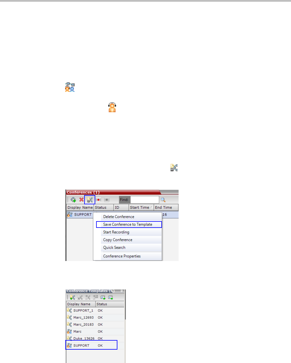
Polycom® RealPresence Collaboration ServerVirtual Edition Administrator’s Guide
9-10 Polycom, Inc.
For more details, see the Polycom® RealPresence Collaboration Server Virtual Edition
Getting Started Guide, "Participants Tab” on page 3-17.
5Optional. Click the Information tab.
The Information tab opens.
6Enter the required information. For more details, see the Polycom® RealPresence
Collaboration Server Virtual Edition Getting Started Guide, "Information Tab” on page 3-20.
7Click OK.
The new Operator conference is added to the ongoing Conferences list with a special icon
.
The Operator participant is displayed in the Participants list with an Operator
participant icon , and the system automatically dials out to the Operator
participant.
Saving an Operator Conference to a Template
The Operator conference that is ongoing can be saved as a template.
To save an ongoing Operator conference as a template:
1In the Conferences List, select the Operator conference you want to save as a Template.
2Click the Save Conference to Template () button.
or
Right-click and select Save Conference to Template.
The conference is saved to a template whose name is taken from the ongoing conference
Display Name (the Login name of the Collaboration Server User). The Template is
displayed with the Operator Conference icon.
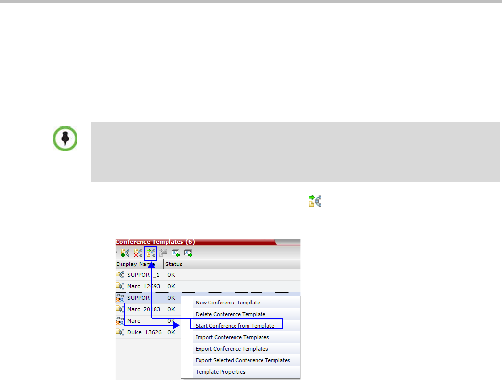
Chapter 9-Operator Assistance & Participant Move
Polycom, Inc. 9-11
Starting an Operator Conference from a Template
An ongoing Operator conference can be started from an Operator Template saved in the
Conference Templates list.
To start an ongoing Operator conference from an Operator Template:
1In the Conference Templates list, select the Operator Template to start as an ongoing
Operator conference.
2Click the Start Conference from Template () button.
or
Right-click and select Start Conference from Template.
The conference is started.
The name of the ongoing conference in the Conferences list is taken from the Conference
Template Display Name.
•You can only start an Operator conference from a template whose name is identical to your Login
Name. For example, if your Login name is Polycom, you can only start an Operator conference
from a template whose name is Polycom.
•If an ongoing Operator conference with the same name or any other conference with the same
ID is already running, you cannot start another Operator conference with the same login name.
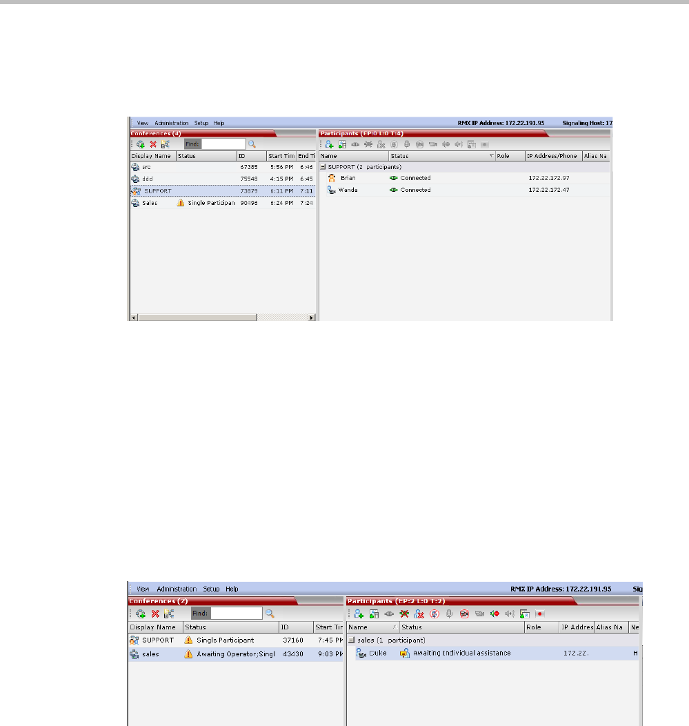
Polycom® RealPresence Collaboration ServerVirtual Edition Administrator’s Guide
9-12 Polycom, Inc.
Monitoring Operator Conferences and Participants Requiring Assistance
Operator conferences are monitored in the same way as standard ongoing conferences.
Each Operator conference includes at least one participant - the Operator.
You can view the properties of the Operator conference by double-clicking the conference
entry in the Conferences list or by right-clicking the conference entry and selecting
Conference Properties. For more information, see the Polycom® RealPresence Collaboration
Server Virtual Edition Getting Started Guide, "Conference Level Monitoring” on page 3-45.
Requesting Help
A participant can request help using the appropriate DTMF code from his/her touch tone
telephone or the endpoint’s DTMF input device. The participant can request Individual
Assistance (default DTMF code *0) or Conference Assistance (default DTMF code 00).
Participants in Entry Queues who failed to enter the correct destination conference ID or the
conference password will wait for operator assistance (provided that an Operator
conference is active).
When requiring or requesting operator assistance, the Collaboration Server management
application displays the following:
• The participant’s connection Status changes, reflecting the help request. For more
information, see Table 9-2.
• The conference status changes and it is displayed with the exclamation point icon and
the status “Awaiting Operator”.
• The appropriate voice message is played to the relevant participants indicating that
assistance will be provided shortly.
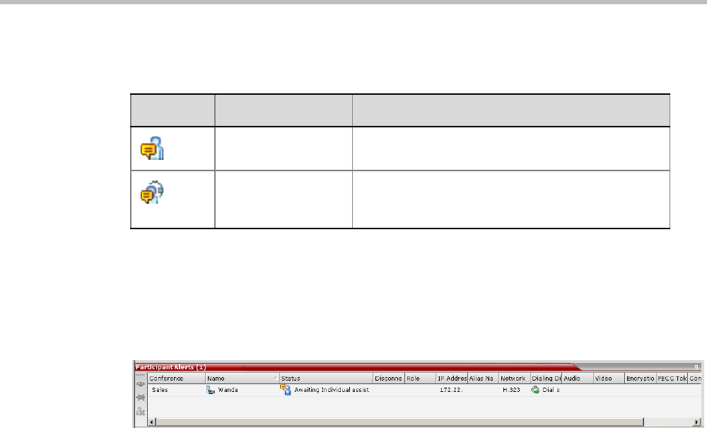
Chapter 9-Operator Assistance & Participant Move
Polycom, Inc. 9-13
The following icons and statuses are displayed in the Participant Status column:
When the Operator moves the participant to the Operator conference for individual assistance
the participant Status indications are cleared.
Participant Alerts List
The Participant Alerts list contains all the participants who are currently waiting for operator
assistance.
Participants are automatically added to the Participants Alerts list in the following
circumstances:
• The participant fails to connect to the conference by entering the wrong conference ID
or conference password and waits for the operator’s assistance
• The participant requests Operator’s Assistance during the ongoing conference
This list is used as reference only. Participants can be assisted and moved to the Operator
conference or the destination conference only from the Participants list of the Entry Queues or
ongoing conference where they are awaiting assistance.
The participants are automatically removed from the Participant Alerts list when moved to
any conference (including the Operator conference).
Audible Alarms
In addition to the visual cues used to detect events occurring on the Collaboration Server, an
audible alarm can be activated and played when participants request Operator Assistance.
Using Audible Alarms
The Audible Alarm functionality for Operator Assistance requests is enabled for each MCU
in either the Collaboration Server Web Client or RMX Manager.
The Audible Alarm played when Operator Assistance is requested is enabled and selected
in the Setup > Audible Alarm > User Customization. When the Audible Alarm is activated,
the *.wav file selected in the User Customization is played, and it is repeated according to the
number of repetitions defined in the User Customization.
Table 9-2 Participants List Status Column Icons and Indications
Icon Status Indication Description
Awaiting Individual
Assistance
The participant has requested the operator’s
assistance for himself/herself.
Awaiting Conference
Assistance
The participant has requested the operator’s
assistance for the conference. Usually this means
that the operator is requested to join the conference.

Polycom® RealPresence Collaboration ServerVirtual Edition Administrator’s Guide
9-14 Polycom, Inc.
If more than one Collaboration Server is monitored in the RMX Manager, the Audible Alarm
must be enabled separately for each Collaboration Server installed in the site/configuration.
A different *.wav file can be selected for each MCU.
When multiple Audible Alarms are activated in different conferences or by multiple MCUs,
the Audible Alarms are synchronized and played one after the other. It is important to note
that when Stop Repeating Alarm is selected from the toolbar from the Collaboration Server
Web Client or RMX Manager, all activated Audible Alarms are immediately halted.
For more details on Audible alarms and their configuration, see "Audible Alarms” on
page 19-31.
Moving Participants Between Conferences
The Collaboration Server User can move participants between ongoing conferences,
including the Operator conference, and from the Entry Queue to the destination conference if
help is required.
When moving between conferences or when a participant is moved from an Entry Queue to
a conference by the Collaboration Server user (after failure to enter the correct destination
ID or conference password), the IVR messages and slide display are skipped.
Move Guidelines
• Move is available only between CP conferences. Move is unavailable from/to Video
Switching conferences.
• Move between conferences can be performed without an active Operator conference.
• When moving the conference chairperson from his/her conference to another
conference, the source conference will automatically end if the Auto Terminate When
Chairperson Exits option is enabled and that participant is the only conference
chairperson.
• When moving the Operator to any conference (following assistance request), the IVR
messages and slide display are skipped.
• Participants cannot be moved from LPR-enabled conferences to non-LPR conferences.
Move from non-LPR conferences to LPR-enabled conferences is available.
• Move between encrypted and non-encrypted conferences depends on the
ALLOW_NON_ENCRYPT_PARTY_IN_ENCRYPT_CONF flag setting, as described
in Table 9-3:
Table 9-3 Participant Move Capabilities vs. ALLOW_NON_
ENCRYPT_PARTY_IN_ENCRYPT_CONF flag setting
Flag
Setting
Source
Conference/
EQ Encrypted
Destination
Conference
Encrypted
Move Enabled?
NO Yes Yes Yes
NO Yes No Yes
NO No Yes No
NO No No Yes
YES Yes Yes Yes
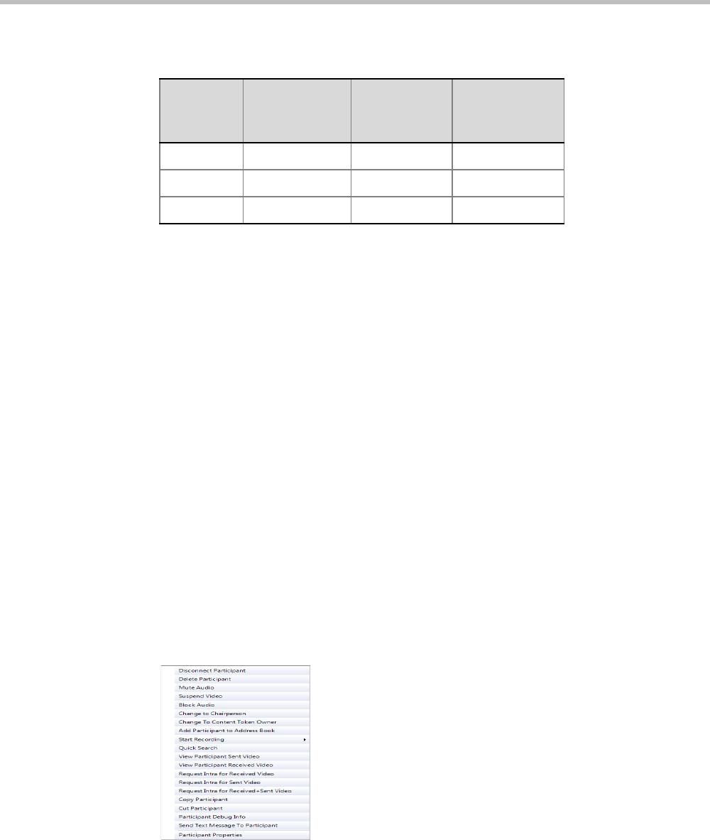
Chapter 9-Operator Assistance & Participant Move
Polycom, Inc. 9-15
• When moving dial-out participants who are disconnected to another conference, the
system automatically dials out to connect them to the destination conference.
• Cascaded links cannot be moved between conferences.
• Participants cannot be moved to a conference if the move will cause the number of
participants to exceed the maximum number of participants allowed for the destination
conference.
Moving Participants Options
Collaboration Server users can assist participants by performing the following operations:
• Move a participant to an Operator conference (Attend a participant).
• Move a participant to the Home (destination) conference.
• Move participant from one ongoing conference to another
A move can be performed using the following methods:
• Using the participant right-click menu
• Using drag and drop
To move a participant from the ongoing conference using the right-click menu options:
1In the Conferences list, click the conference where there are participants waiting for
Operator’s Assistance to display the list of participants.
2In the Participants list, right-click the icon of the participant to move and select one of
the following options:
—Move to Operator Conference - to move the participant to the Operator
conference.
—Move to Conference - to move the participant to any ongoing conference.
YES Yes N o Yes
YES No Yes Yes
YES No No Yes
Table 9-3 Participant Move Capabilities vs. ALLOW_NON_
ENCRYPT_PARTY_IN_ENCRYPT_CONF flag setting (Continued)
Flag
Setting
Source
Conference/
EQ Encrypted
Destination
Conference
Encrypted
Move Enabled?

Polycom® RealPresence Collaboration ServerVirtual Edition Administrator’s Guide
9-16 Polycom, Inc.
When selected, the Move to Conference dialog box opens, letting you select the name
of the destination conference.
—Back to Home Conference - if the participant was moved to another conference or
to the Operator conference, this options moves the participant back to his/her source
conference.
This option is not available if the participant was moved from the Entry Queue to
the Operator conference or the destination conference.
Moving a Participant Interactively
You can drag and drop a participant from the Entry Queue or ongoing conference to the
Operator or destination (Home) conference:
1Display the participants list of the Entry Queue or the source conference by clicking its
entry in the Conferences list.
2In the Participants list, drag the icon of the participant to the Conferences List pane and
drop it on the Operator Conference icon or another ongoing conference.

Polycom, Inc. 10-1
10
Conference Templates
Conference Templates enable administrators and operators to create, save, schedule and
activate identical conferences.
A Conference Template:
• Saves the conference Profile.
• Saves all participant parameters including their Personal Layout and Video Forcing
settings.
Guidelines
• The maximum number of templates is 100.
Trying to start a Conference Template that exceeds the allowed maximum number of
participants will result in participants being disconnected due to resource deficiency.
• If the Profile assigned to a conference is deleted while the conference is ongoing the
conference cannot be saved as a template.
• A Profile assigned to a Conference Template cannot be deleted. The system does not
permit such a deletion.
• Profile parameters are not embedded in the Conference Template, and are taken from the
Profile when the Conference Template becomes an ongoing conference. Therefore, any
changes to the Profile parameters between the time the Conference Template was created
and the time that it is activated (and becomes an ongoing conference) will be applied to
the conference.
• Only defined participants can be saved to the Conference Template. Before saving a
conference to a template ensure that all undefined participants have disconnected.
• Undefined participants are not saved in Conference Templates.
• Participant properties are embedded in the Conference Template and therefore, if the
participant properties are modified in the Address Book after the Conference Template
has been created they are not applied to the participant whether the Template becomes
an ongoing conference or not.
•The Conference Template display name, routing name or ID can be the same as an
Ongoing Conference, reservation, Meeting Room or Entry Queue as it is not active.
However, an ongoing conference cannot be launched from the Conference Template if an
ongoing conference, Meeting Room or Entry Queue already has the same name or ID.
Therefore, it is recommended to modify the template ID, display name, routing name to
be unique.
• SIP Factories and Entry Queues cannot be saved as Conference Templates.
• The conference specified in the Conference Template can be designated as a Permanent
Conference. For more information see "Lecture Mode (AVC CP Only)” on page 3-38.
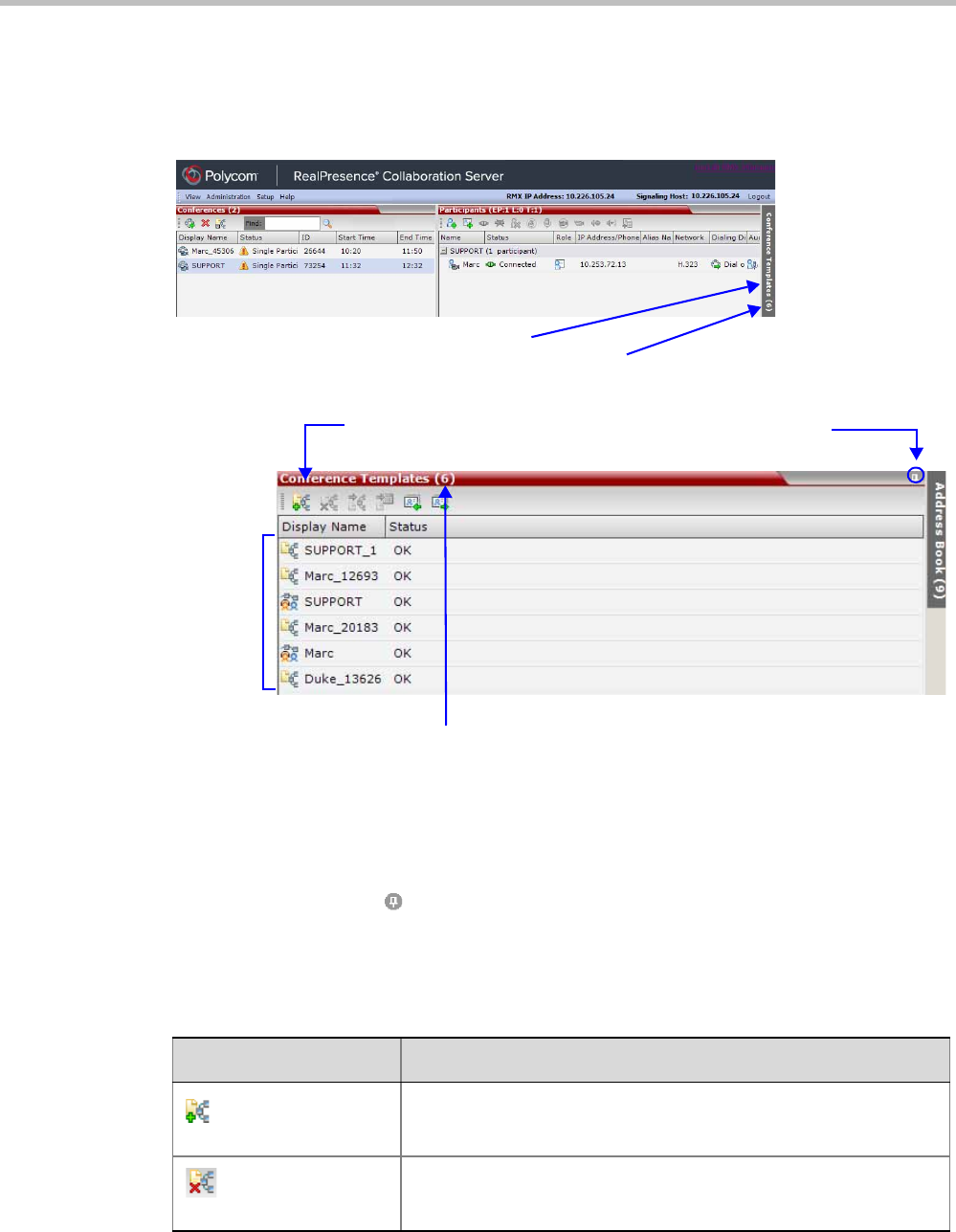
Polycom® RealPresence Collaboration ServerVirtual Edition Administrator’s Guide
10-2 Polycom, Inc.
Using Conference Templates
The Conference Templates list is initially displayed as a closed tab in the Collaboration Server
Web Client main window. The number of saved Conference Templates is indicated on the tab.
Clicking the tab opens the Conference Templates list.
The Conference Templates are listed by Conference Template Display Name and ID and can be
sorted by either field. The list can be customized by re-sizing the pane, adjusting the column
widths or changing the order of the column headings.
For more information see Polycom® RealPresence Collaboration Server Virtual Edition Getting
Started Guide, "Customizing the Main Screen” on page 3-10.
Clicking the anchor pin ( ) button hides the Conference Templates list as a closed tab.
Toolbar Buttons
The Conference Template toolbar includes the following buttons:
Conference Templates Tab
Number of Saved Conference Templates
Toolbar buttons
Number of Saved Conference Templates
List of
Saved
Templates
Click to hide the
Conference Templates List
Table 1 Conference Templates – Toolbar Buttons
Button Description
New Conference
Template
Creates a new Conference Template.
Delete Conference
Template
Deletes the Conference Template(s) that are selected in the list.
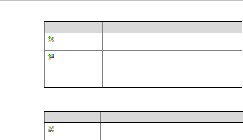
Chapter 10-Conference Templates
Polycom, Inc. 10-3
The Conferences List toolbar includes the following button:
Start Conference
from Template
Starts an ongoing conference from the Conference Template that has
an identical name, ID parameters and participants as the template.
Schedule Reservation
from Template
Creates a conference Reservation from the Conference Template
with the same name, ID, parameters and participants as the
Temp la te.
Opens the Scheduler dialog box enabling you to modify the fields
required to create a single or recurring Reservation based on the
template. For more information see "Reservations” on page 9-1.
Table 1 Conference Templates – Toolbar Buttons (Continued)
Button Description
Table 2 Conferences List – Toolbar Button
Button Description
Save Conference to
Template Saves the selected ongoing conference as a Conference Template.
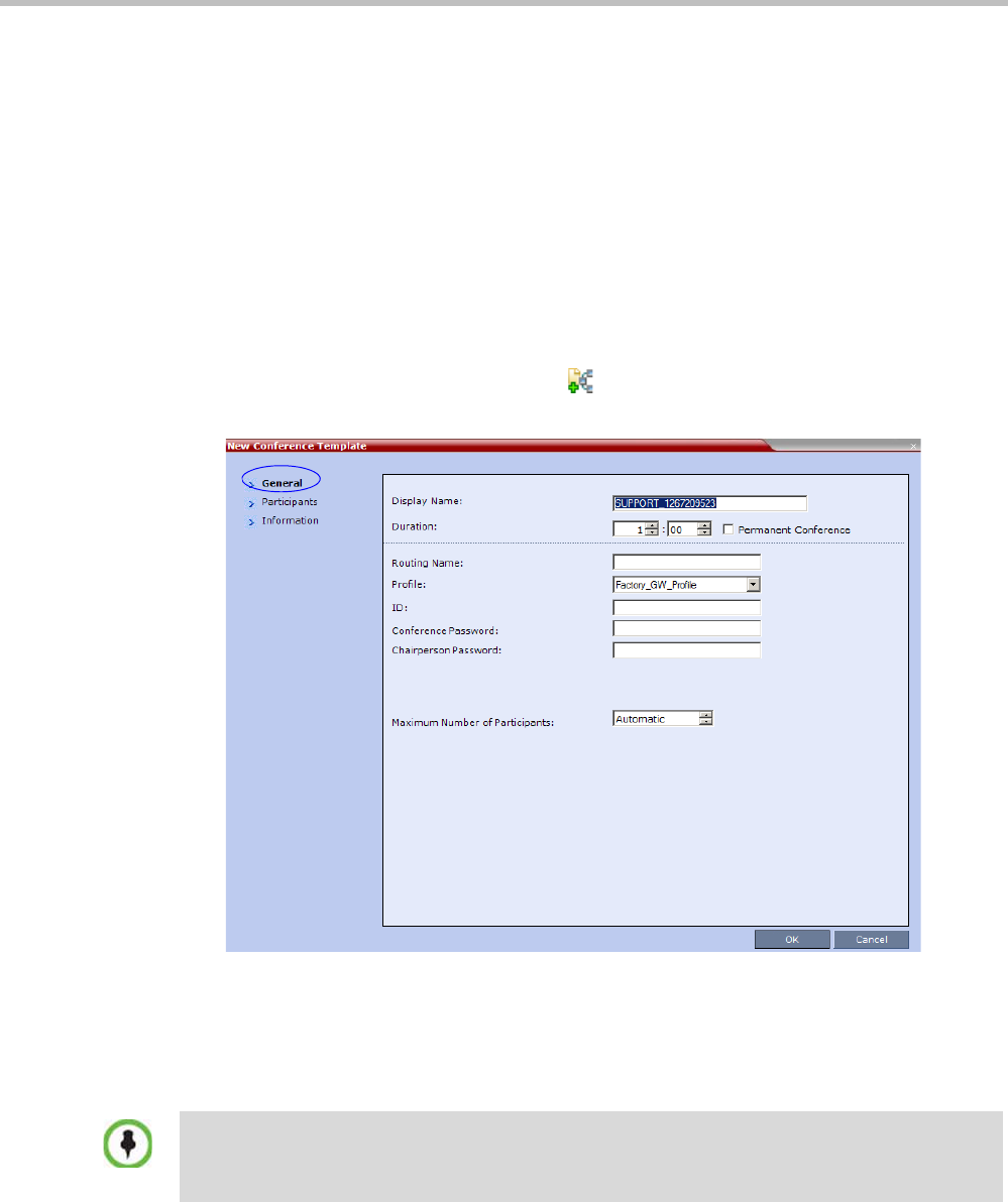
Polycom® RealPresence Collaboration ServerVirtual Edition Administrator’s Guide
10-4 Polycom, Inc.
Creating a New Conference Template
There are two methods to create a Conference Template:
• From scratch - defining the conference parameters and participants
• Saving an ongoing conference as Template
Creating a new Conference Template from Scratch
To create a new Conference Template:
1In the Collaboration Server Polycom® RealPresence Collaboration Server Virtual Edition
Administrator’s Guide, click the Conference Templates tab.
2Click the New Conference Template ( ) button.
The New Conference Template - General dialog box opens.
3The fields of the New Template – General dialog box are identical to those of the New
Conference – General dialog box. For a full description of the fields see the Polycom®
RealPresence Collaboration Server Virtual Edition Getting Started Guide, "General Tab” on
page 3-14.
4Modify the fields of the General tab.
5Click the Participants tab.
A unique dial-in number must be assigned to each conferencing entity. However, Conference
Templates can be assigned dial-in numbers that are already assigned to other conferencing entities,
but when the template is used to start an ongoing conference or schedule a reservation, it will not
start if another ongoing conference, Meeting Room, or Entry Queue is using this number.
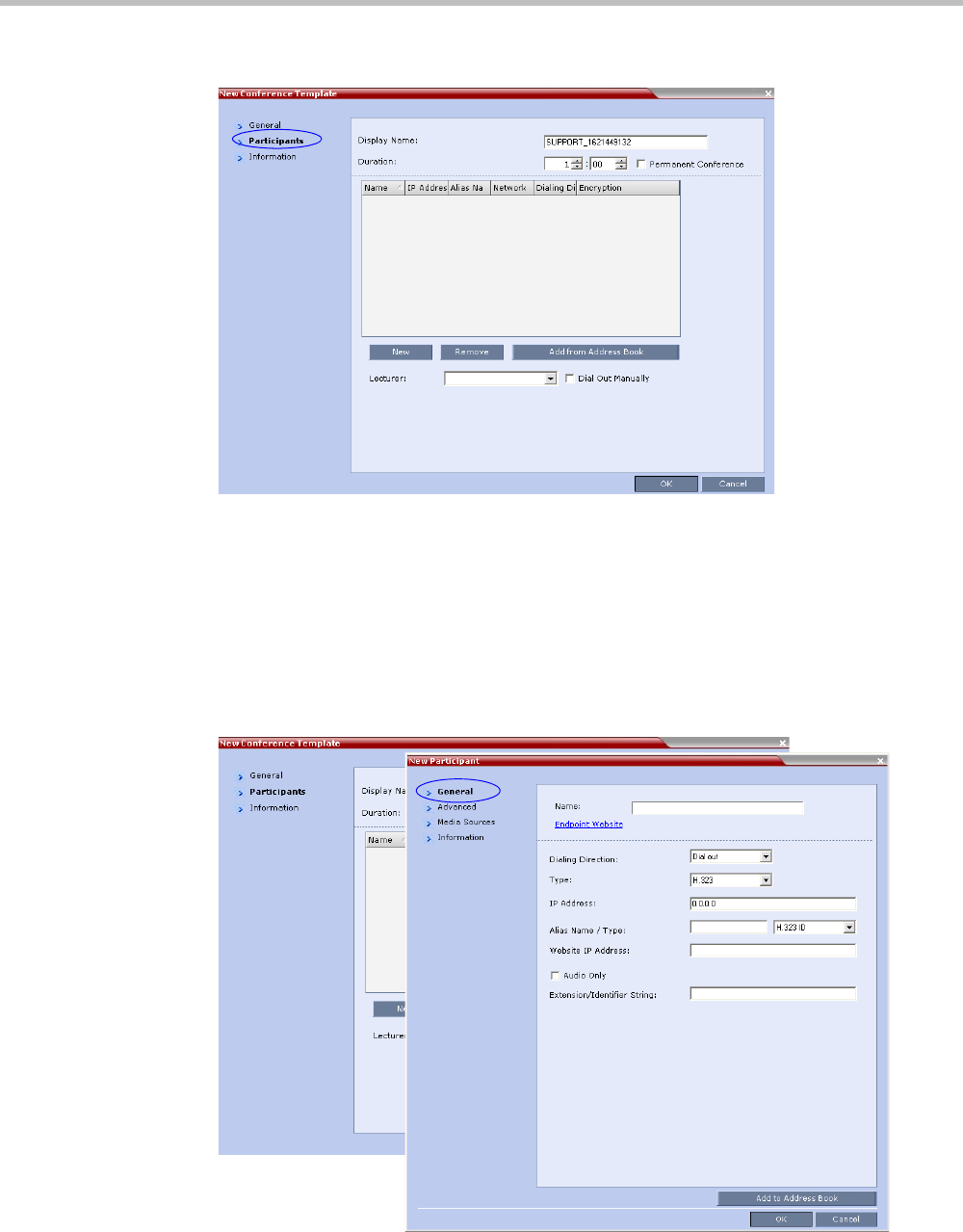
Chapter 10-Conference Templates
Polycom, Inc. 10-5
The New Template – Participants dialog box opens.
The fields of the New Template – Participants dialog box are the same as those of the New
Conference – Participant dialog box.
For a full description of these fields see the Polycom® RealPresence Collaboration Server
Virtual Edition Getting Started Guide, "Participants Tab” on page 3-17.
6Optional. Add participants to the template from the Address Book.
7Click the New button.
The New Participant – General tab opens.
The New Template – Participant dialog box remains open in the background.
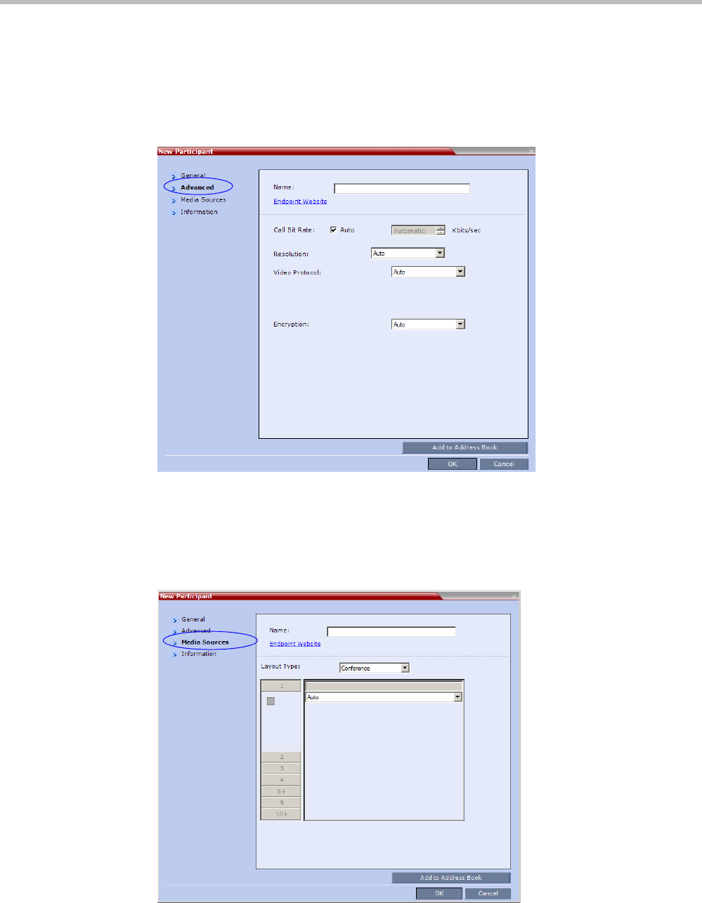
Polycom® RealPresence Collaboration ServerVirtual Edition Administrator’s Guide
10-6 Polycom, Inc.
For a full description of the General tab fields see "Adding a New participant to the Address
Book Directly” on page 8-8.
8Modify the fields of the General tab.
9Click the Advanced tab.
The New Participant – Advanced tab opens.
For a full description of the Advanced tab fields see, "New Participant – Advanced
Properties” on page 8-12.
10 Modify the fields of the Advanced tab.
11 Click the Media Sources tab.
The Media Sources tab opens.
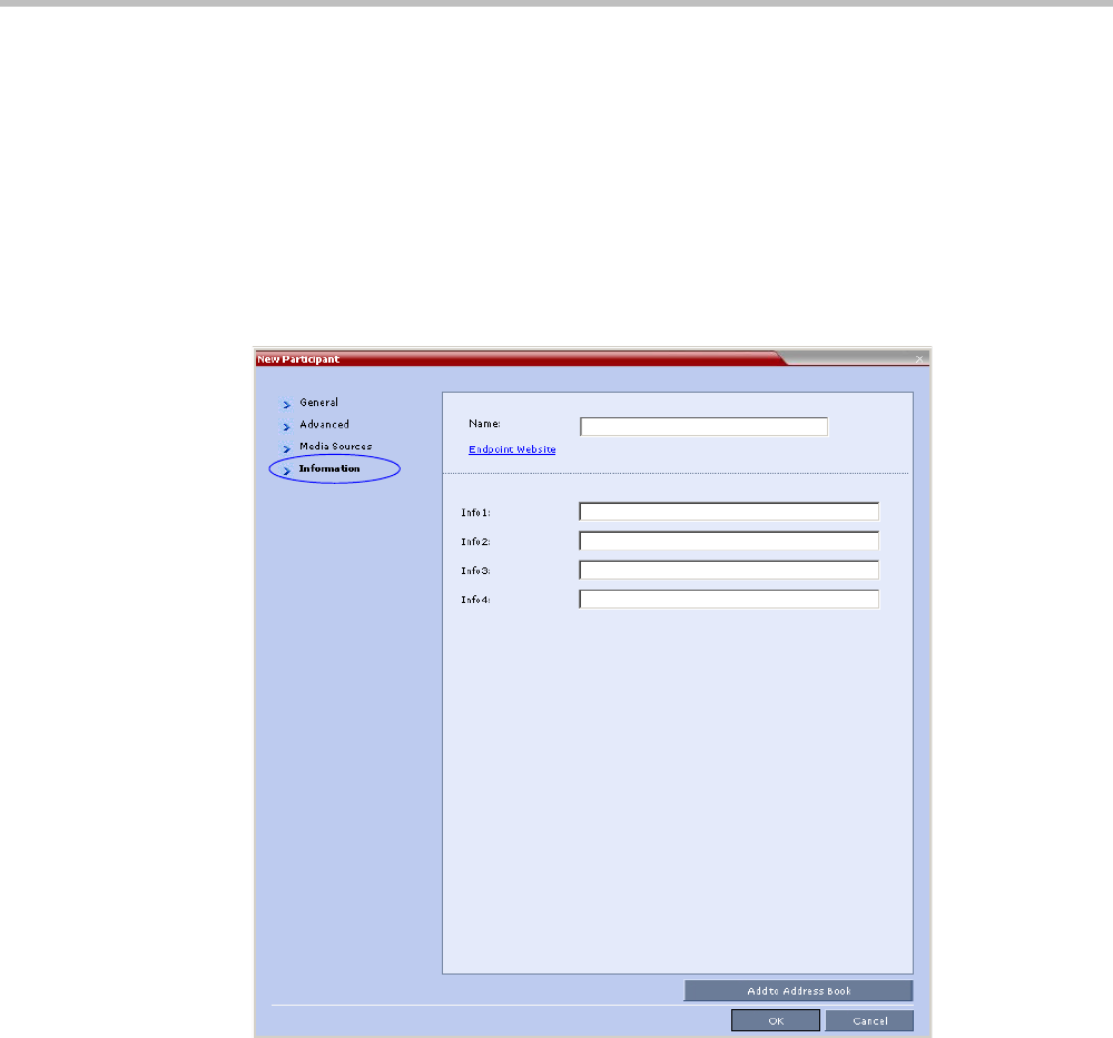
Chapter 10-Conference Templates
Polycom, Inc. 10-7
The Media Sources tab enables you to set up and save Personal Layout and Video Forcing
settings for each participant.
For a full description of Personal Layout and Video Forcing settings see the Polycom®
RealPresence Collaboration Server Virtual Edition Getting Started Guide, "Changing the Video
Layout of a Conference (AVC-Based CP and Mixed CP and SVC Conferences)” on page 3-59
and "Video Forcing (AVC-Based CP and Mixed CP and SVC Conferences)” on page 3-61.
12 Modify the Personal Layout and Video Forcing settings for the participant.
13 Optional. Click the Information tab.
The New Participant – Information tab opens.
For a full description of the Information fields see the Polycom® RealPresence Collaboration
Server Virtual Edition Getting Started Guide, "Information Tab” on page 3-20.
14 Click the OK button.
The participant you have defined is added to the Participants List.
The New Participant dialog box closes and you are returned to the New Template –
Participant dialog box (which has remained open since Step 7).
15 Optional. In the New Conference Template dialog box, click the Information tab.
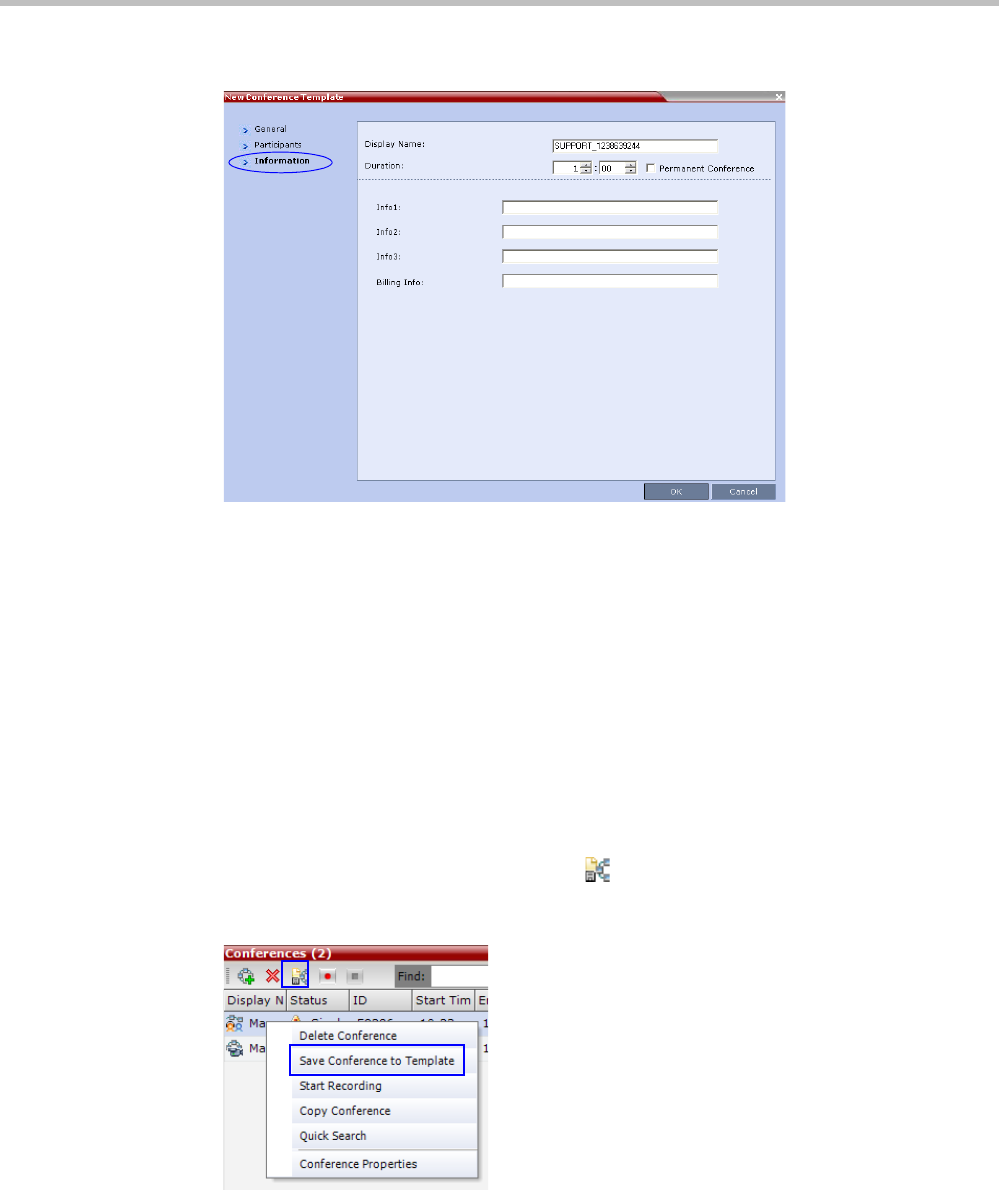
Polycom® RealPresence Collaboration ServerVirtual Edition Administrator’s Guide
10-8 Polycom, Inc.
The New Conference Template – Information tab opens.
For a full description of the Information fields see the Polycom® RealPresence Collaboration
Server Virtual Edition Getting Started Guide, “Information Tab” on page 20.
16 Click the OK button.
The New Conference Template is created and its name is added to the Conference Templates
list.
Saving an Ongoing or AVC-based CP Operator Conference as a Template
Any ongoing or AVC-based CP Operator Conference can be saved as a template.
To save an ongoing or AVC-based CP Operator Conference as a template:
1In the Conferences List, select the conference or Operator Conference to be saved as a
Template.
2Click the Save Conference to Template () button.
or
Right-click and select Save Conference to Template.
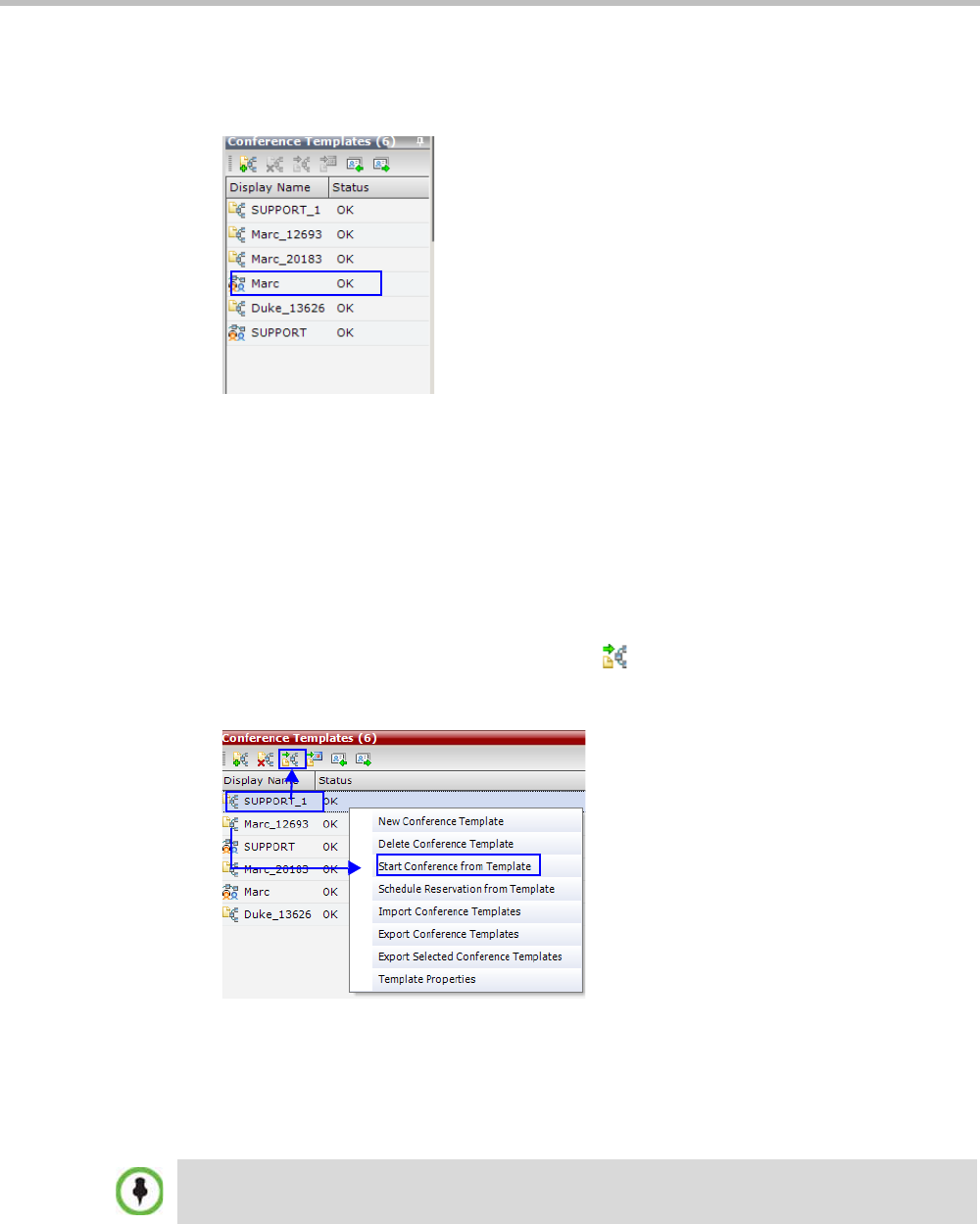
Chapter 10-Conference Templates
Polycom, Inc. 10-9
The conference is saved to a template whose name is taken from the ongoing conference
Display Name (the Login name of the Collaboration Server User). The Template is displayed
with the Operator Conference icon.
Starting an Ongoing Conference From a Template
An ongoing conference can be started from any Template saved in the Conference Templates
list. In SVC-based templates, only defined dial-in participants may be part of the conference.
To start an ongoing conference from a Template:
1In the Conference Templates list, select the Template you want to start as an ongoing
conference.
2Click the Start Conference from Template () button.
or
Right-click and select Start Conference from Template.
The conference is started.
The name of the ongoing conference in the Conferences list is taken from the Conference
Template Display Name.
Participants that are connected to other ongoing conferences when the template
becomes an ongoing conference are not connected.
If an ongoing conference, Meeting Room or Entry Queue with the same Display Name, Routing
Name or ID already exists in the system, the conference will not be started.
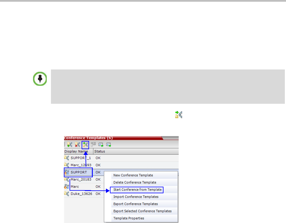
Polycom® RealPresence Collaboration ServerVirtual Edition Administrator’s Guide
10-10 Polycom, Inc.
Starting an Operator Conference from a Template (AVC Conferencing)
An ongoing Operator conference can be started from an Operator Template saved in the
Conference Templates list.
To start an ongoing Operator conference from an Operator Template:
1In the Conference Templates list, select the Operator Template to start as an ongoing
Operator conference.
2Click the Start Conference from Template () button.
or
Right-click and select Start Conference from Template.
The conference is started.
The name of the ongoing conference in the Conferences list is taken from the Conference
Template Display Name.
Deleting a Conference Template
One or several Conference Templates can be deleted at a time.
To delete Conference Templates:
1In the Conference Templates list, select the Template(s) you want to delete.
•You can only start an Operator conference from a template whose name is identical to your Login
Name. For example, if your Login name is Polycom, you can only start an Operator conference
from a template whose name is Polycom.
•If an ongoing Operator conference with the same name or any other conference with the same
ID is already running, you cannot start another Operator conference with the same login name.
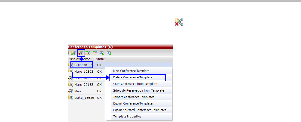
Chapter 10-Conference Templates
Polycom, Inc. 10-11
2Click the Delete Conference Template () button.
or
Right-click and select Delete Conference Template.
A confirmation dialog box is displayed.
3Click the OK button to delete the Conference Template(s).
Exporting and Importing Conference Templates
Conference Templates can be exported from one MCU and imported to multiple MCUs in
your environment. Additionally, you can export Conference Templates and their associated
Conference Profiles simultaneously. Using this option can save configuration time and
ensures that identical settings are used for conferences running on different MCUs. This is
especially important in environments using cascading conferences that are running on
different MCUs.
• Administrators can export and import Conference Templates. Operators are only allowed
to export Conference Templates.
• You can select a single, multiple or all Conference Templates to be exported.
•Both Conference Templates and their associated Conference Profiles can be exported and
imported simultaneously when enabling the Export includes conference profiles or
Import includes conference profiles options.
• Exporting and importing Conference Templates only can be used when you want to
export and import individual Conference Templates without their associated Conference
Profiles. This option enables you to import Conference Templates when Conference Profiles
already exist on an MCU.
Exporting Conference Templates
Conference Templates are exported to a single XML file that can be used to import the
Conference Templates on multiple MCUs.
Using the Export Conference Templates option, you can:
•Export all Conference Templates from an MCU
•Export selected Conference Templates
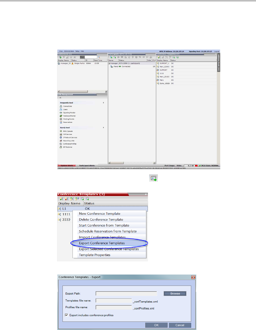
Polycom® RealPresence Collaboration ServerVirtual Edition Administrator’s Guide
10-12 Polycom, Inc.
Exporting All Conference Templates from an MCU
To export all Conference Templates from an MCU:
1In the Collaboration Server Web Client main window, click the Conference Templates tab.
The Conference Templates list pane is displayed.
2Click the Export Conference Templates button or right-click the Conference
Templates list, and then click Export Conference Templates.
The Conference Templates - Export dialog box is displayed.
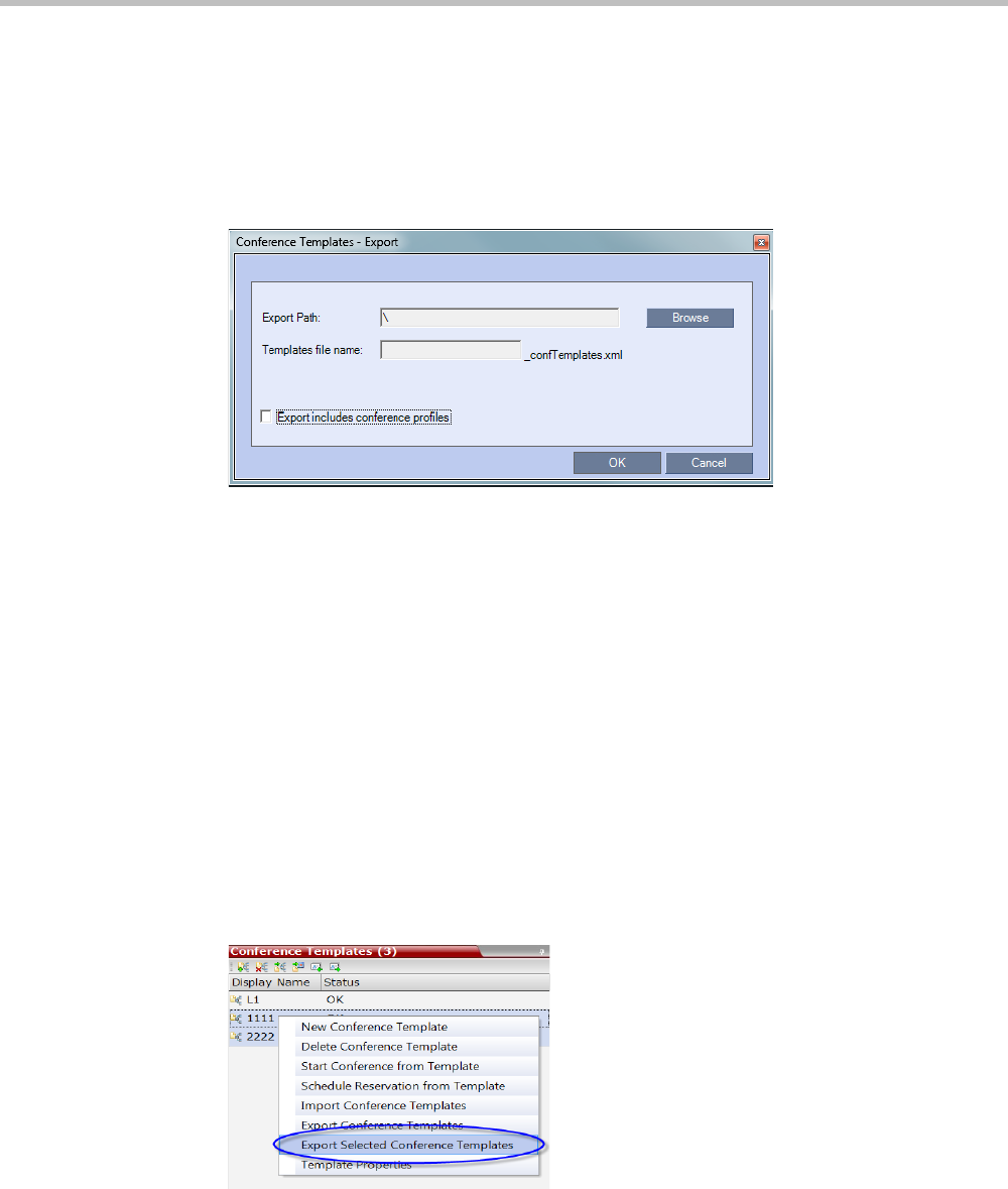
Chapter 10-Conference Templates
Polycom, Inc. 10-13
3In the Export Path field, type the path name to the location where you want to save the
exported file or click Browse to select the desired path.
4Optional. Clear the Export includes conference profiles check box when you only want
to export Conference Templates.
When this check box is cleared, the Conference Templates - Export dialog box is displayed
without the Profiles file name field.
5In the Templates file name field, type the file name prefix. The file name suffix
(_confTemplates.xml) is predefined by the system. For example, if you type
Templates01, the exported file name is defined as Templates01_confTemplates.xml.
The system automatically defines the Profiles file name field with the same file name
prefix as the Templates file name field. For example, if you type Templates01 in the
Templates file name field, the exported profiles file name is defined as
Templates01_confProfiles.xml.
6Click OK to export the Conference Templates and Conference Profiles to a file.
Exporting Selected Conference Templates
You can export a single Conference Template or multiple Conference Templates to other MCUs
in your environment.
To export selected Conference Templates:
1In the Conference Templates list, select the templates you want to export.
2Right-click the Conference Templates to be exported, and then click Export Selected
Conference Templates.
.
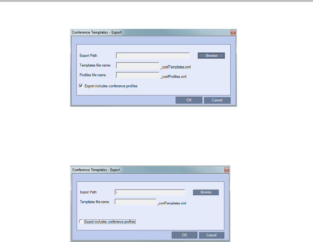
Polycom® RealPresence Collaboration ServerVirtual Edition Administrator’s Guide
10-14 Polycom, Inc.
The Conference Templates - Export dialog box is displayed.
3In the Export Path field, type the path name to the location where you want to save the
exported file or click Browse to select the desired path.
4Optional. Clear the Export includes conference profiles check box when you only want
to export Conference Templates.
When this check box is cleared, the Conference Templates - Export dialog box is displayed
without the Profiles file name field.
5In the Templates file name field, type the file name prefix. The file name suffix
(_confTemplates.xml) is predefined by the system. For example, if you type,
Templates01, the exported file name is defined as Templates01_confTemplates.xml.
The system automatically defines the Profiles file name field with the same file name
prefix as the Templates file name field. For example, if you type Templates01 in the
Templates file name field, the exported profiles file name is defined as
Templates01_confProfiles.xml.
6Click OK to export the Conference Templates and Conference Profiles to a file.
Importing Conference Templates
You can import Conference Templates and Conference Profiles from one MCU to multiple
MCUs in your environment.
To import Conference Templates:
1In the Collaboration Server Web Client main window, click the Conference Templates tab.
The Conference Templates are displayed.
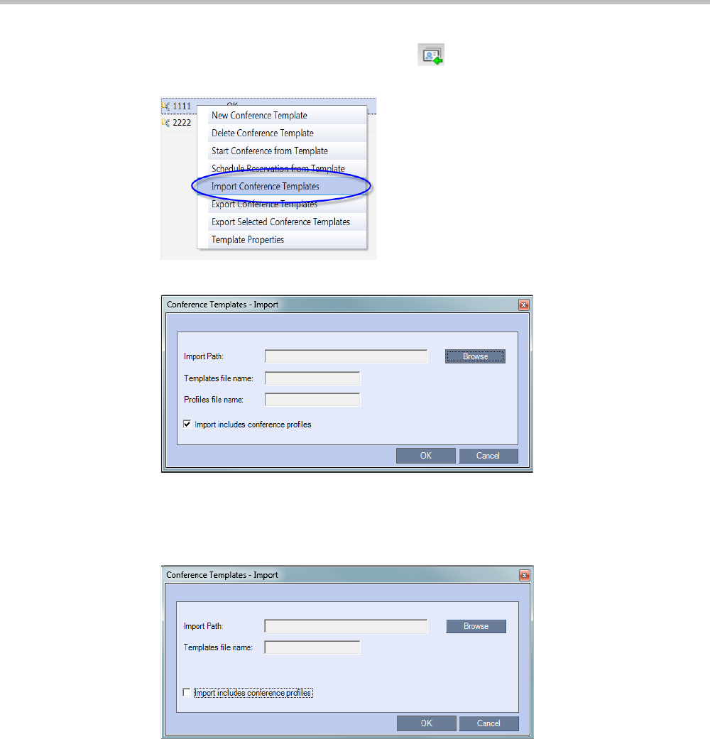
Chapter 10-Conference Templates
Polycom, Inc. 10-15
2Click the Import Conference Templates button or right-click the Conference
Templates pane, and then click Import Conference Templates.
The Conference Templates - Import dialog box is displayed.
3Optional. Clear the Import includes conference profiles check box when you only
want to import Conference Templates.
When this check box is cleared, the Conference Templates - Import dialog box is displayed
without the Profiles file name field.
4In the Import Path field, click Browse to navigate to the path and file name of the
Conference Templates you want to import.
When clicking the exported templates file you want to import, the system automatically
displays the appropriate files in the Templates file name field and the Profiles file name
field (when the Import includes conference profiles check box is selected).
5Click OK to import the Conference Templates and their associated Conference Profiles, if
selected.
Conference Templates are not imported when:
—A Conference Template already exists
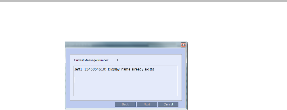
Polycom® RealPresence Collaboration ServerVirtual Edition Administrator’s Guide
10-16 Polycom, Inc.
—An associated Conference Profile is not defined in the Conference Profiles list
When one or more Conference Templates are not imported, a Message Alert window is
displayed with the templates that were not imported.
6Click Cancel to exit the Message Alerts window.
The imported Conference Templates are added to the Conference Templates list. When the
Import includes conference profiles check box is selected, the imported Conference
Profiles are added to the Conference Profiles list.
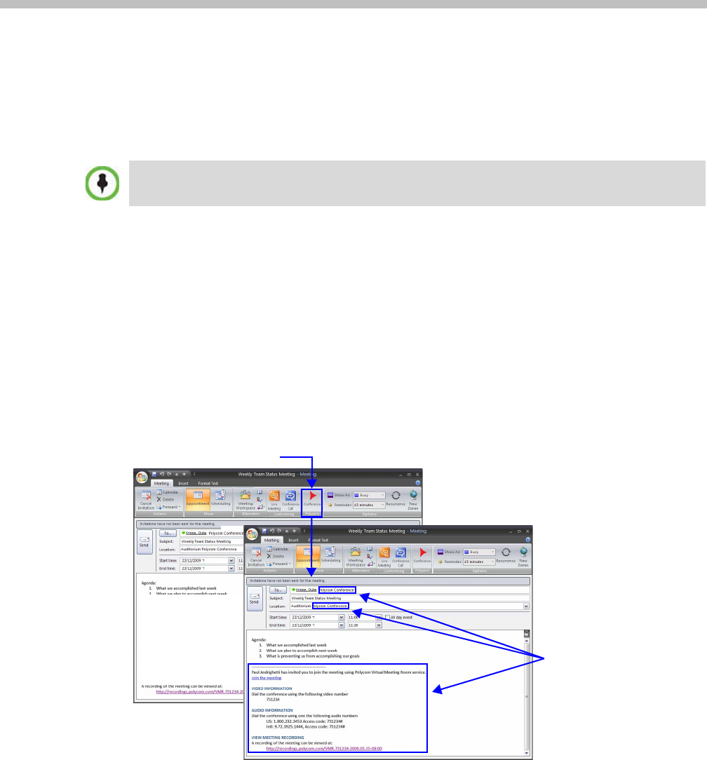
Polycom, Inc. 11-1
11
Polycom Conferencing for Microsoft
Outlook®
Polycom Conferencing for Microsoft Outlook is an add-in that enables users to easily organize
and invite attendees to Video Enabled meetings via Microsoft Outlook®.
Polycom Conferencing for Microsoft Outlook is implemented by installing the Polycom
Conferencing Add-in for Microsoft Outlook on Microsoft Outlook® e-mail clients. It enables
meetings to be scheduled with video endpoints from within Outlook. The add-in also adds a
Polycom Conference button in the Meeting tab of the Microsoft Outlook e-mail client ribbon.
The meeting organizer clicks the Polycom Conference button to add Conference Information
to the meeting invitation.
Attendees call the meeting at the scheduled Start Time using the link or the dial-in number
provided in the meeting invitation.
Polycom Conferencing for Microsoft Outlook is supported in AVC CP Conferencing Mode only.
Polycom Conference Button
Conference
Information
Added
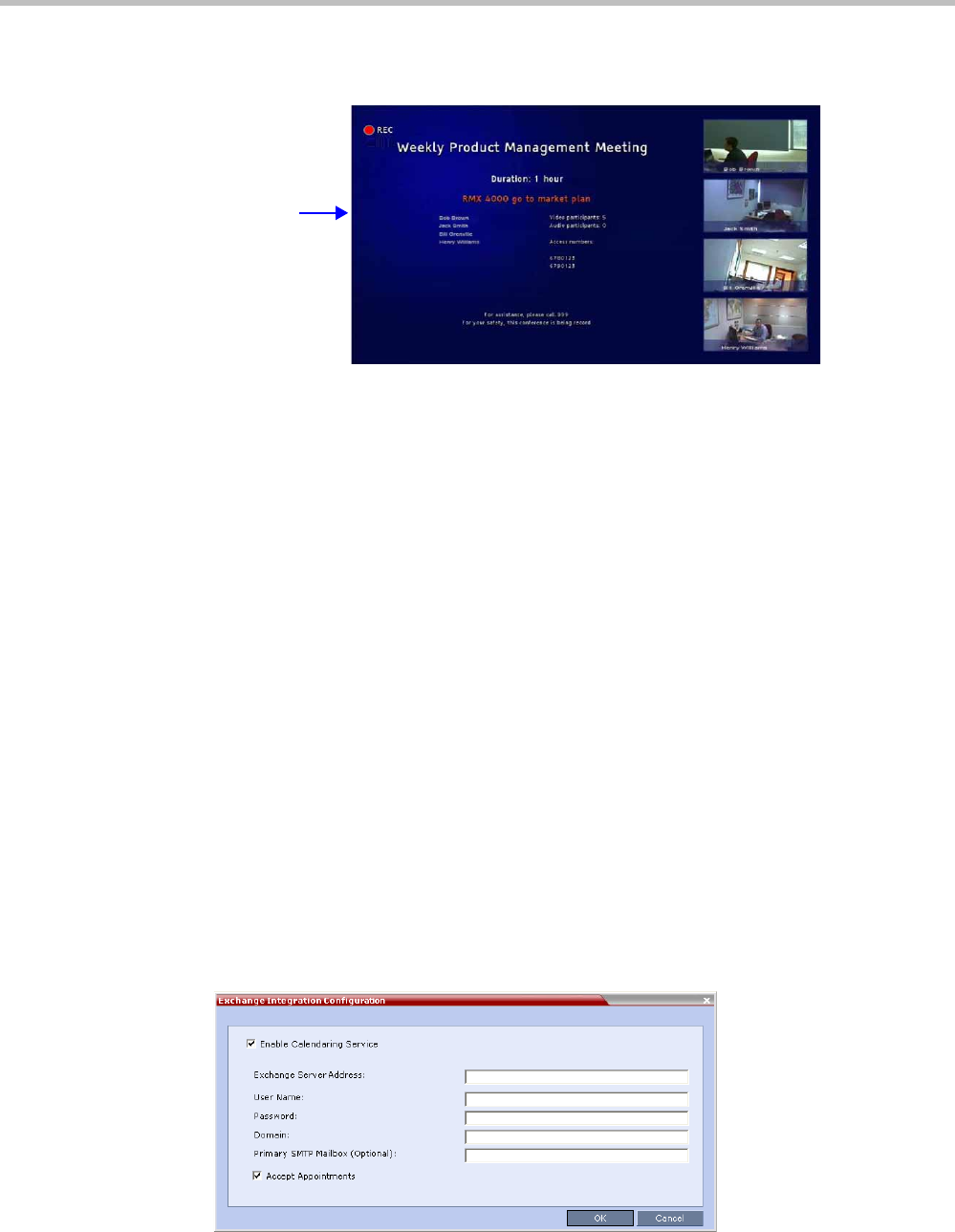
Polycom® RealPresence Collaboration ServerVirtual Edition Administrator’s Guide
11-2 Polycom, Inc.
A Gathering Slide is displayed to connected participants until the conference starts.
The Gathering Slide displays live video along with information taken from the meeting
invitation such as the subject, meeting organizer, duration, dial-in numbers etc. At the end
of the Gathering Phase, the conference layout is displayed.
For more information see "Video Preview (AVC Only Participants)” on page 3-20.
Setting up the Calendaring Solution
The following steps are performed to set up the Calendaring solution:
AThe administrator installs the Polycom Conferencing Add-in for Microsoft for Microsoft
Outlook e-mail clients. For more information, see the Polycom Unified Communications
Deployment Guide for Microsoft Environments.
BThe administrator creates an Microsoft Outlook e-mail-account for the Collaboration
Server.
If included in the solution, Polycom RealPresence DMA system and calendaring-enabled
endpoints share this e-mail account. For more information, see the Polycom Unified
Communications Deployment Guide for Microsoft Environments.
CThe administrator configures the Collaboration Server for Calendaring using the
Exchange Integration Configuration dialog box, providing it with the Microsoft Exchange
Server Name, User Name and Password and optional Primary SMTP Mail box
information needed to access the e-mail account.
To configure the Collaboration Server’s Exchange Integration Configuration:
1On the Collaboration Server menu, click Setup > Exchange Integration Configuration.
The Exchange Integration Configuration dialog box is displayed.
Gathering Slide:
Displays Meeting
Information Until
Conference Starts
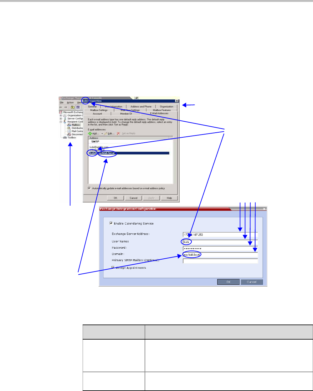
Chapter 11-Polycom Conferencing for Microsoft Outlook®
Polycom, Inc. 11-3
There are three options that can be used to configure the Exchange Integration
Configuration. The option you choose will depend on the configuration of the mailbox in
the Exchange Server and the configuration of the Exchange Server itself.
—Option 1 - Use this option if the Exchange Server settings have been left at their
default values.
—Option 2 - Use this option if the Primary SMTP Mailbox is not the default mailbox.
—Option 3 - Use this option if the Exchange Server settings have been modified by the
administrator.
Option 1 - Using default Exchange Server settings
aDefine the following fields:
Mailbox Properties
Default
Mailbox
Name
Required
Fields
Exchange
Management
Console
Default
Domain
Name
Table 11-1 Exchange Integration Configuration - Option 1
Field Description
Enable Calendaring
Service
Select or clear this check box to enable or disable the
Calendaring Service using the Polycom Add-in for Microsoft
Outlook. When this check box is cleared all fields in the dialog
box are disabled.
Exchange Server
Address
Enter the IP address of the Exchange Server.

Polycom® RealPresence Collaboration ServerVirtual Edition Administrator’s Guide
11-4 Polycom, Inc.
bClick the OK button.
User Name Enter the User Name of the Collaboration Server, as registered
in the Microsoft Exchange Server, that the Collaboration Server
uses to login to its e-mail account.
Field length: Up to 80 characters.
Password Enter the Password the Collaboration Server uses to login to its
e-mail account as registered in the Microsoft Exchange Server.
Field length: Up to 80 characters.
Domain Enter the name of the network domain where the Collaboration
Server is installed as defined in the Microsoft Exchange Server.
Primary SMTP
Mailbox (Optional)
This field is left empty.
Accept Appointments Select this check box to enable the Collaboration Server to send
replies to meeting invitations.
Clear this check box when the Collaboration Server is part of a
Unified Conferencing solution that includes a RealPresence
DMA system, as the RealPresence DMA system will send a
reply to the meeting invitation.
Table 11-1 Exchange Integration Configuration - Option 1 (Continued)
Field Description
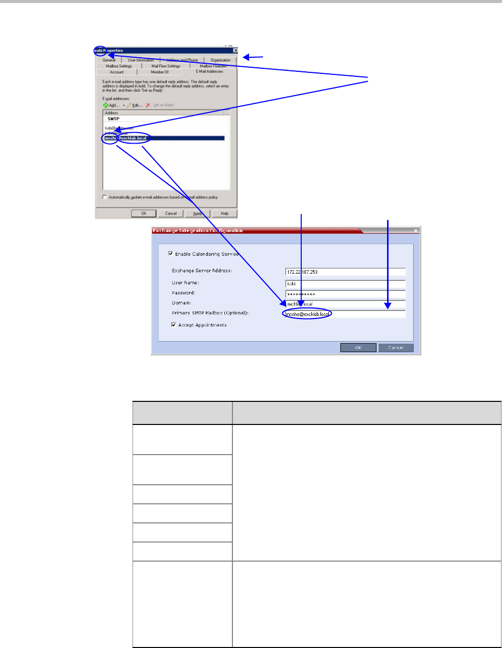
Chapter 11-Polycom Conferencing for Microsoft Outlook®
Polycom, Inc. 11-5
Option 2 - Using an alternate Primary SMTP Mailbox
aDefine the following fields:
Mailbox Properties
Different
Mailbox
Names
Additional
Required
Field
Primary
SMTP
Mailbox
Table 11-2 Exchange Integration Configuration - Option 2
Field Description
Enable Calendaring
Service
These fields are defined as for Option 1 above.
Exchange Server
Address
User Name
Password
Domain
Accept Appointments
Primary SMTP
Mailbox (Optional)
Enter the name of the SMTP Mailbox in the Microsoft Exchange
Server to be monitored by the Collaboration Server.
Note: Although several mailboxes can be assigned to each user
in the Microsoft Exchange Server, only the Primary SMTP
Mailbox is monitored. The Primary SMTP Mailbox name does
not have to contain either the Collaboration Server’s User Name
or Domain name.
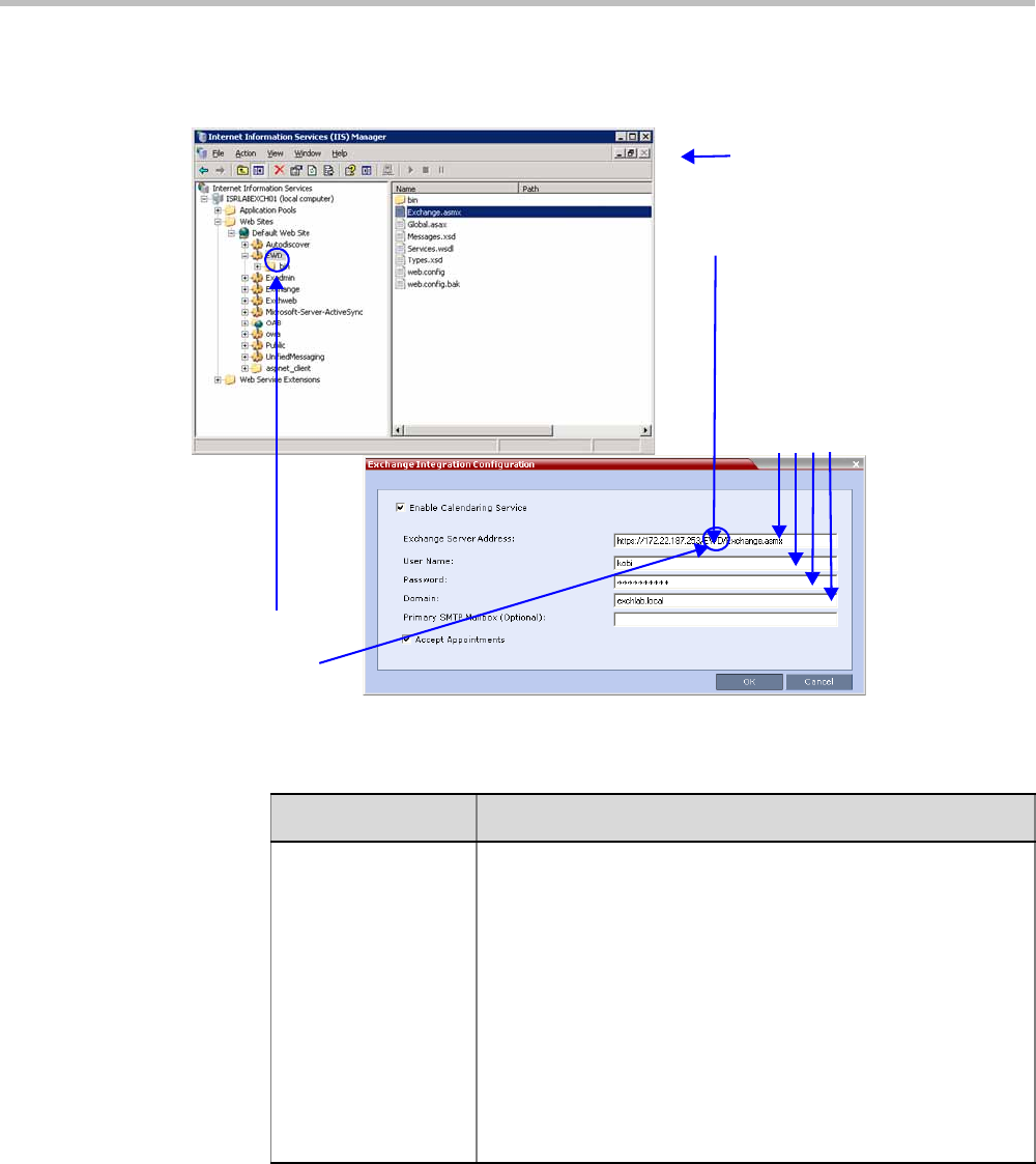
Polycom® RealPresence Collaboration ServerVirtual Edition Administrator’s Guide
11-6 Polycom, Inc.
bClick the OK button.
Option 3 - Using modified Exchange Server settings
aDefine the following fields:
Exchange Web
Services Folder
Renamed from
EWS to EWD
Required
Fields
Full path to
Exchange Server
IIS Manager
Table 11-3 Exchange Integration Configuration - Option 3
Field Description
Exchange Server
Address
If Exchange Server settings have been modified, enter the full
path to the Microsoft Exchange Server where the Collaboration
Server’s Microsoft Outlook e-mail account is registered, for
example if the EWS folder has been renamed EWD:
https://labexch01/EWD/Exchange.asmx
Note: If a server name is entered, the Collaboration Server and
the Microsoft Exchange Server must be registered to the same
Domain. (The Domain name entered in this dialog box must
match the Local Domain Name entry in the Management
Network - DNS Properties dialog box.)
For more information see "Modifying the Default IP Network
Service” on page 16-6.
Field length: Up to 80 characters.
Chapter 11-Polycom Conferencing for Microsoft Outlook®
Polycom, Inc. 11-7
bClick the OK button.
If applicable, RSS, VMC, RealPresence DMA system, and calendaring-enabled endpoints
are configured with the Exchange Server Name, User Names and Passwords needed to
access their accounts.
For more information see the Polycom Unified Communications Deployment Guide for
Microsoft Environments.
2The administrator configures the Collaboration Server to have a default Ad-hoc Entry
Queue service enabled.
For more information see "Defining a New Entry Queue” on page 7-3.
Calendaring Guidelines
• The Collaboration Server must have its MCU prefix registered in the gatekeeper.
For more information see "Modifying the Default IP Network Service” on page 16-6.
• The Collaboration Server must be configured as a Static Route.
For more information see "Modifying the Default IP Network Service” on page 16-6.
• The Collaboration Server’s Default Entry Queue must be configured as an Ad Hoc Entry
Queue and must be designated as the Transit Entry Queue.
For more information see the "Entry Queues” on page 7-1.
• The meeting organizer can enable recording and/or streaming of the meeting.
• If meeting is to be recorded, the Ad Hoc Entry Queue must have recording enabled in its
Profile.
For more information see "Defining New Profiles” on page 2-20.
• Meetings can be single instance or have multiple occurrences.
• Attendees that do not have video devices may be invited to the meeting.
• Attendees using e-mail applications that use the iCalendar format may be invited to
meetings via the Calendaring Service.
• Meeting invitations sent by Polycom Conferencing for Microsoft Outlook can be in a
different language to the Collaboration Server Web Client. The following languages are
supported:
—English
—French
—German
Enable Calendaring
Service
These fields are defined as for Option 1 above.
User Name
Password
Domain
Primary SMTP
Mailbox (Optional)
Accept Appointments
Table 11-3 Exchange Integration Configuration - Option 3 (Continued)
Field Description

Polycom® RealPresence Collaboration ServerVirtual Edition Administrator’s Guide
11-8 Polycom, Inc.
—International Spanish
—Korean
—Japanese
—Simplified Chinese
• Collaboration Server resource management is the responsibility of the system
administrator:
—Conferences initiated by Polycom Conferencing for Microsoft Outlook are ad hoc
and therefore resources are not reserved in advance.
—Polycom Conferencing for Microsoft Outlook Add-in assumes that sufficient
resources are available and does not check resource availability. Sufficient
resources are therefore not guaranteed.
—A meeting invitation that is automatically accepted by the Collaboration Server is
not guaranteed availability of resources.
—If the Collaboration Server runs out of resources, attendees will not be able to
connect to their conferences.
• By using RealPresence DMA system to load-balance resources between several
Collaboration Servers, resource capacity can be increased, alleviating resource
availability problems.
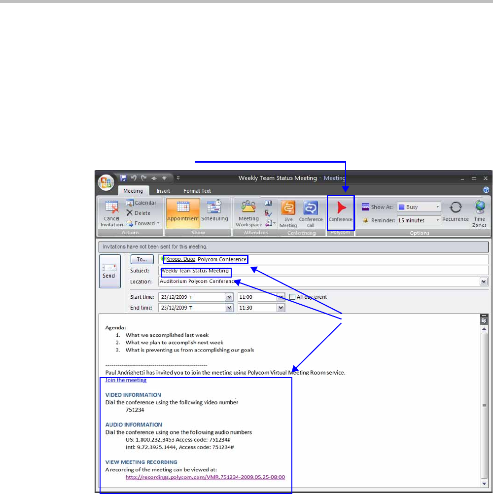
Chapter 11-Polycom Conferencing for Microsoft Outlook®
Polycom, Inc. 11-9
Creating and Connecting to a Conference
Creating a Conference
Meetings are organized using the Microsoft Outlook client in the normal manner.
If the meeting organizer decides that video participants are to be included in a multipoint
video conference, he/she clicks the Polycom Conference button. Conference Information such
as the Meeting ID and connection information is automatically added to the existing
appointment information.
The meeting organizer can add a meeting agenda or personal text to the invitation before it
is sent. The meeting organizer can update or cancel the video enabled meeting in the same
manner as for any other meeting.
When the meeting organizer sends the meeting invitation a meeting record is saved in the
Microsoft Exchange Server, the RealPresence Collaboration Server, RealPresence DMA system,
RSS and calendaring-enabled endpoints.
RealPresence Collaboration Servers, RealPresence DMA system, and calendaring-enabled
endpoints poll the Microsoft Exchange Server to retrieve new meeting records and updates to
existing meeting records.
Polycom Conference Button
Conference
Information

Polycom® RealPresence Collaboration ServerVirtual Edition Administrator’s Guide
11-10 Polycom, Inc.
Table 11-4 summarizes the Collaboration Server’s usage of Microsoft Outlook data fields
included in the meeting invitation.
Connecting to a Conference
Participants can connect to the conference in the following ways:
• Participants with Polycom CMA Desktop™ or a Microsoft Office Communicator client
running on their PCs can click on a link in the meeting invitation to connect to the
meeting.
• Participants with a HDX or a room system will receive a prompt from the endpoint’s
calendaring system along with a button that can be clicked in order to connect.
Participants with endpoints that are not calendaring-enabled can connect to the
meeting by dialing the meeting number manually.
Collaboration Server Standalone Deployment
When using a single Collaboration Server in a standalone deployment, connection is via an
Ad Hoc Entry Queue. The meeting is started when the first participant connects to the
Collaboration Server.
Table 11-4 Microsoft Outlook Field Usage
Microsoft
Outlook Field
Usage by the Collaboration Server / RealPresence DMAsystem
Conference / Meeting Room Gathering Slide
Subject Display Name of Conference / Meeting
Room.
Meeting Name.
Start/End Time Used to calculate the Conference’s Duration.
Record Enable Recording in the Conference or
Meeting Room Profile.
Display Recording option.
Video Access
Number
Comprised of: <MCU Prefix in
Gatekeeper>
<Conference Numeric ID>.
Note: It is important that MCU Prefix in
Gatekeeper field in the Collaboration
Server’s IP Network Service -
Gatekeeper tab and the Dial-in prefix
field in the Polycom Conferencing Add-
in for Microsoft Outlook - Video Network
tab contain the same prefix information.
Displayed as the IP dial in number
in the Access Number section of
the Gathering Slide.
Video Access
Number (Cont.)
If Recording and Streaming are enabled
in the Conference Profile, this number
is used as part of the recording file
name.
Streaming
recording link
Enables the recording of the
conference to the Polycom RSS using
the recording link.
Enables streaming of the recording of
the conference from the Polycom RSS.
If recording is enabled, a REC
indicator is displayed in the top left
corner of the slide.

Chapter 11-Polycom Conferencing for Microsoft Outlook®
Polycom, Inc. 11-11
When the first participant connects, a conference is created and named according to the
information contained in the dial string. Subsequent participants connecting with the same
dial string are routed from the Ad Hoc Entry Queue to the conference.
After the conference has been created the Conference Name, Organizer, Time, Duration and
Password (if enabled) are retrieved from the conference parameters for display during the
Gathering Phase.
Collaboration Server and Polycom RealPresence DMA System
Deployment
In a RealPresence DMA system deployment a Virtual Meeting Room is activated when the
first participant connects to the RealPresence DMA system. The RealPresence DMA system
receives the dial string to activate a Virtual Meeting Room on the Collaboration Server.
The RealPresence DMA system uses the Meeting ID contained in the dial-in string to access
meeting information stored in the Exchange Server database.
When the meeting information is found on the Exchange Server, the Conference Name,
Organizer, Time, Duration and Password (if enabled) are retrieved from the Exchange Server
database for display during the Gathering Phase.
Polycom Solution Support
Polycom Implementation and Maintenance services provide support for Polycom solution
components only. Additional services for supported third-party Unified Communications
(UC) environments integrated with Polycom solutions are available from Polycom Global
Services and its certified Partners. These additional services will help customers successfully
design, deploy, optimize and manage Polycom visual communications within their UC
environments.
Professional Services for Microsoft Integration is mandatory for Polycom Conferencing for
Microsoft Outlook and Microsoft Office Communications Server integrations. For additional
information and details please see http://www.polycom.com/services/
professional_services/index.html or contact your local Polycom representative.
If enabled, automatically generated passwords are ignored.
For more information see "Automatic Password Generation Flags” on page 20-37.

Polycom® RealPresence Collaboration ServerVirtual Edition Administrator’s Guide
11-12 Polycom, Inc.

Polycom, Inc. 12-1
12
Conference and Participant
Monitoring
You can monitor ongoing conferences and perform various operations while conferences
are running.
Three levels of monitoring are available with the Collaboration Server:
•General Monitoring - You can monitor the general status of all ongoing conferences and
their participants in the main window.
•Conference Level Monitoring - You can view additional information regarding a specific
conference and modify its parameters if required, using the Conference Properties option.
•Participant Level Monitoring - You can view detailed information on the participant's
status, using the Participant Properties option.
• The maximum number of participants in a conference:
—In SVC Only conference: up to 60 SVC-based participants
—In CP Only conference: up to 20 AVC-based HD participants or 40 AVC-based SD
participants
—In a Mixed CP and SVC conference: any combination of SVC and AVC-based
participants depending on the number of AVC and SVC participants.
Viewing Permissions
Chairperson
Administrator
Operator
Tab
Skins
IVR
Info
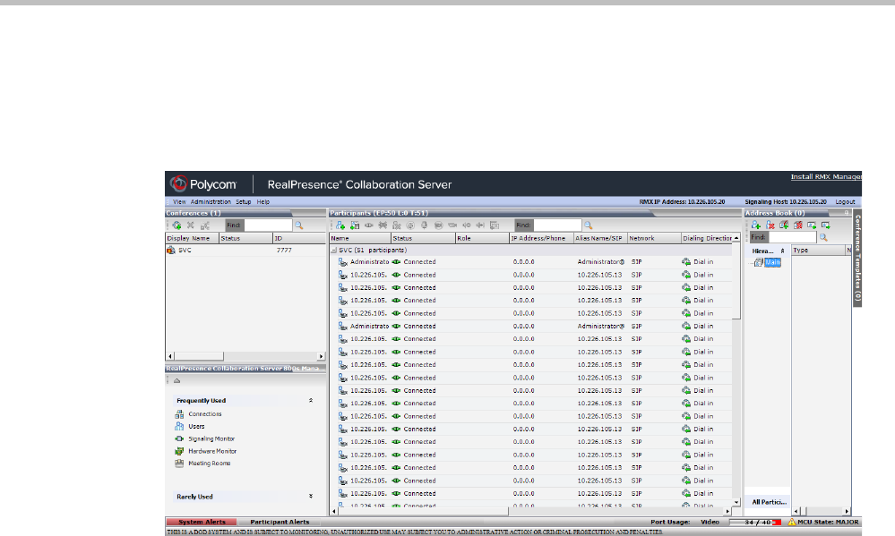
Polycom® RealPresence Collaboration ServerVirtual Edition Administrator’s Guide
12-2 Polycom, Inc.
General Monitoring
Users can monitor a conference or keep track of its particiRealPresence Collaboration
Serverpants and progress. For more information, see Polycom® RealPresence Collaboration
Server Virtual Edition Getting Started Guide, "Monitoring Ongoing Conferences” on page 3-43.
You can click the blinking Participant Alerts indication bar to view participants that require
attention. For more information, see "System and Participant Alerts” on page 19-1.
Conference Level Monitoring
In addition to the general conference information that is displayed in the Conference list
pane, you can view the details of the conference’s current status and setup parameters,
using the Conference Properties dialog box.
Viewing the Properties of an Ongoing AVC CP and Mixed CP and SVC
Conference
To view the parameters of an ongoing AVC CP conference:
1In the Conference list pane, double-click the AVC CP conference or right-click the AVC
CP conference and then click Conference Properties.
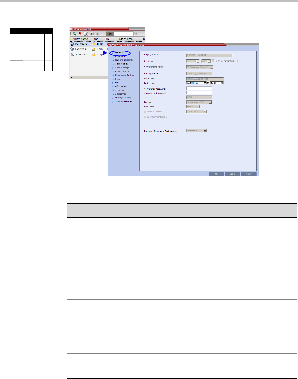
Chapter 12-Conference and Participant Monitoring
Polycom, Inc. 12-3
The Conference Properties - General dialog box with the General tab opens.
The following information is displayed in the General tab:
Viewing Permissions
Chairperson
Administrator
Operator
Tab
General
Table 12-1 Conference Properties - General
Field Description
Display Name The Display Name is the conference name in native language and
Unicode character sets to be displayed in the Collaboration Server
Web Client.
Note: This field is displayed in all tabs.
Duration The expected duration of the conference using the format HH:MM.
Note: This field is displayed in all tabs.
Permanent
Conference
Indicates whether the conference is set as a Permanent Conference,
with no pre-determined End Time. This conference continues until it
is terminated by an administrator, operator or chairperson.
Note: This field is displayed in all tabs.
Routing Name The ASCII name of the conference. It can be used by H.323 and SIP
participants for dialing in directly to the conference. It is used to
register the conference in the gatekeeper and the SIP server.
Conferencing Mode The conferencing mode set for the conference: CP, VSW, SVC only
or CP and SVC.
Start Time The time the conference started.
End Time The expected conference end time.
Note: This field is not shown when the conference is set as a
Permanent Conference.
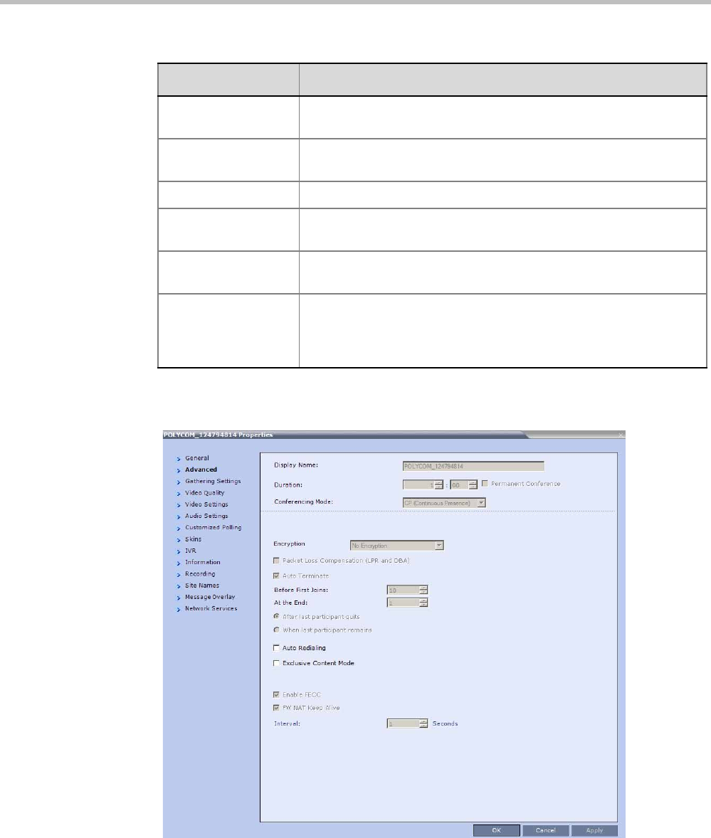
Polycom® RealPresence Collaboration ServerVirtual Edition Administrator’s Guide
12-4 Polycom, Inc.
2Click the Advanced tab.
The Conference Properties - Advanced dialog box opens.
Conference
Password
A numeric password for participants to access the conference.
Chairperson
Password
A numeric password used by participants to identify themselves as
the conference chairperson.
ID The conference ID.
Profile The name of the conference Profile from which conference
parameters were taken.
Line Rate The maximum transfer rate, in kilobytes per second (Kbps) of the call
(video and audio streams).
Max Number of
Participants
Indicates the total number of participants that can be connected to
the conference. The Automatic setting indicates the maximum
number of participants that can be connected to the MCU according
to resource availability.
Table 12-1 Conference Properties - General (Continued)
Field Description
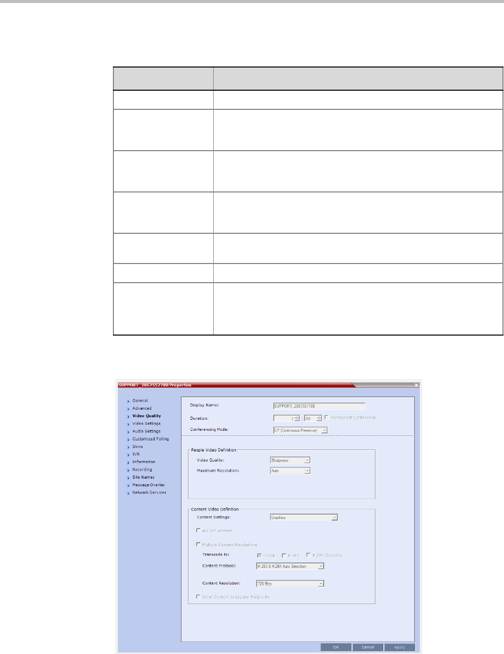
Chapter 12-Conference and Participant Monitoring
Polycom, Inc. 12-5
3The following information is displayed in the Advanced tab:
4Click the Video Quality tab.
The Conference Properties - Video Quality dialog box opens.
Table 12-2 Conference Properties - Advanced Parameters
Field/Option Description
Encryption Indicates whether the conference is encrypted.
Packet Loss
Compensation (LPR
and DBA)
Indicates wether Packet Loss Compensation (LPR and DBA) is
enabled for the conference.
Auto Terminate When selected, indicates that the MCU will automatically terminate
the conference when Before First Joins, At the End-After Last Quits
and At the End - When Last Participant Remains parameters apply.
Auto Redialing Indicates whether dial-out participants are automatically (when
selected) or manually (when cleared) connected to the conference.
This option is disabled in mixed CP and SVC conferences.
Exclusive Content
Mode
When selected, Content is limited to one participant.
Enable FECC When selected, Far End Camera Control is enabled.
FW NAT Keep Alive When selected, sends a FW NAT Keep Alive message at specific
Intervals for the RTP, UDP and BFCP channels. The interval specifies
how often a FW NAT Keep Alive message is sent. For more
information, see

Polycom® RealPresence Collaboration ServerVirtual Edition Administrator’s Guide
12-6 Polycom, Inc.
The following information is displayed:
Table 12-3 Conference Properties - Video Quality Parameters
Field/Option Description
People Video Definition
Video Quality Indicates the resolution and frame rate that determine the video
quality set for the conference. This is always Sharpness. For more
information, see "Video Resolutions in AVC-based CP Conferencing”
on page 4-1.
Maximum Resolution Indicates the Maximum Resolution setting for the conference.
•Auto (default) - indicates that the Maximum Resolution is as
selected in the Resolution Configuration dialog box.
The Maximum Resolution settings for conferences and participants
cannot be changed during an ongoing conference.
Content Video Definition
AS-SIP This option is not supported with RealPresence Collaboration Server
Virtual Edition.
Multiple Content
Resolutions
This option is not supported with RealPresence Collaboration Server
Virtual Edition.
Content Settings Indicates the Content channel resolution set for the conference.
Possible resolutions are:
•Graphics – default mode
•Hi-res Graphics – requiring a higher bit rate
•Live Video – content channel is live video
•Customized Content Rate - resolution is manually defined.
Content Protocol Indicates the Content Protocol used for content sharing in Highest
Common Content Sharing Mode.
For more information, see "Content Protocols” on page 3-8.
Content Resolution Indicates the Content Resolution and frame rate according to the
selected Content Sharing Mode (Highest common Content or Multiple
Resolution Contents) and the video protocol. For more information,
see "Defining Content Sharing Parameters for a Conference” on
page 3-3.
Send Content to
Legacy Endpoints
(CP only)
This Content Sharing option is not supported with RealPresence
Collaboration Server Virtual Edition.
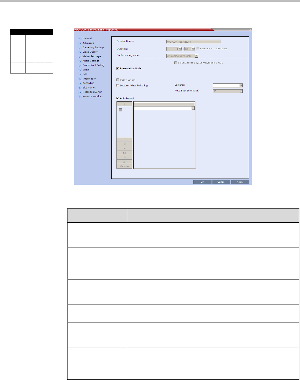
Chapter 12-Conference and Participant Monitoring
Polycom, Inc. 12-7
5Click the Video Settings tab to list the video parameters.
Viewing Permissions
Chairperson
Administrator
Operator
Tab
Video
Settings
Table 12-4 Conference Properties - Video Settings Parameters
Field Description
Presentation Mode When checked, indicates that the Presentations Mode is active. This
option is disabled in a mixed CP and SVC conference.
For more information, see .
Lecturer View
Switching
When checked, the Lecturer View Switching enables automatic
random switching between the conference participants in the lecturer
video window.
This option is disabled in a mixed CP and SVC conference.
Same Layout When checked, forces the selected layout on all conference
participants, and the Personal Layout option is disabled.
This option is disabled in a mixed CP and SVC conference.
Auto Layout When enabled, the system automatically selects the conference
layout based on the number of participants in the conference.
Lecturer Indicates the name of the lecturer (if one is selected). Selecting a
lecturer enables the Lecture Mode.
This option is disabled in a mixed CP and SVC conference.
Auto Scan Interval(s) The time interval, 10 - 300 seconds, that Auto Scan uses to cycle the
display of participants that are not in the conference layout in the
selected cell.
This option is disabled in a mixed CP and SVC conference.
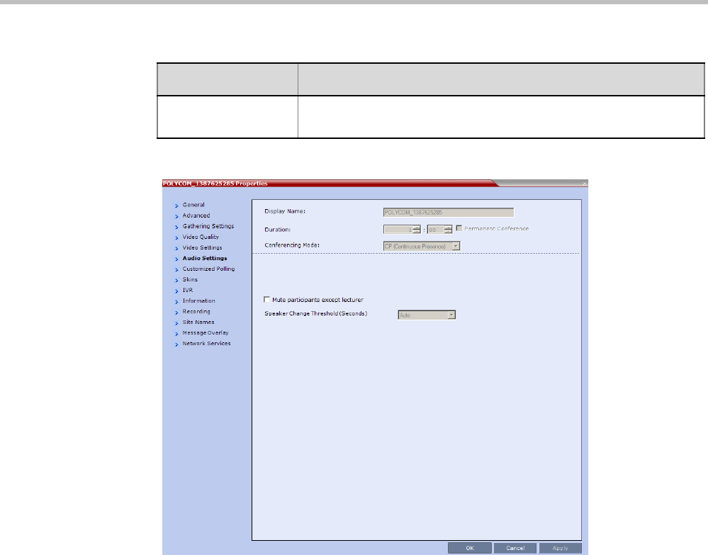
Polycom® RealPresence Collaboration ServerVirtual Edition Administrator’s Guide
12-8 Polycom, Inc.
6Click the Audio Settings tab to view the audio setting for the conference.
7If needed, you can enable or disable the Mute participants except lecturer setting.
Video Layouts
(graphic)
Indicates the currently selected video layout.
Table 12-4 Conference Properties - Video Settings Parameters (Continued)
Field Description
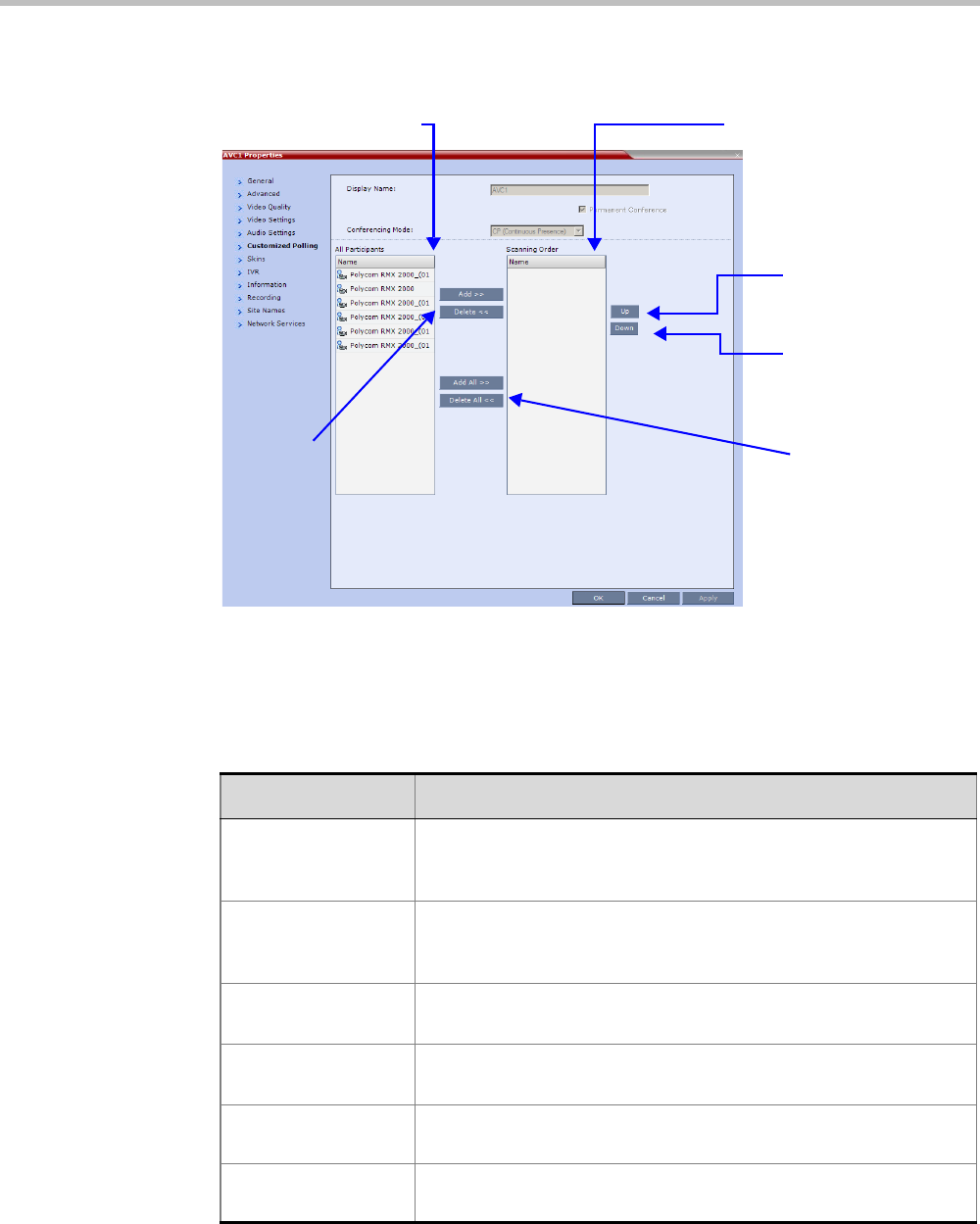
Chapter 12-Conference and Participant Monitoring
Polycom, Inc. 12-9
8CP Only Conferences: Click the Customized Polling tab to view and modify the
customized polling for the conference.
All conference participants are listed in the left pane (All Participants) while the
participants that are to be displayed in the Auto Scan enabled cell of the video layout
are listed in the right pane (Scanning Order).
The dialog box buttons are summarized in Table 12-5.
All Conference Participants Scanning Order
Move
participant up
in Scanning
Order
Move
participant
down in
Scanning Order
Add /
Delete Add All /
Delete All
Table 12-5 Customized Polling - Buttons
Button Description
Add Select a participant and click this button to Add a the participant to the
list of participants to be Auto Scanned.
The participants name is removed from the All Participants pane.
Delete Select a participant and click this button to Delete the participant from
the list of participants to be Auto Scanned.
The participants name is moved back to the All Participants pane.
Add All Add all participants to the list of participants to be Auto Scanned.
All participants’ names are removed from the All Participants pane.
Delete All Delete all participant from the list of participants to be Auto Scanned.
All participants’ names are moved back to the All Participants pane.
Up Select a participant and click this button to move the participant Up in
the Scanning Order.
Down Select a participant and click this button to move the participant Down
in the Scanning Order.
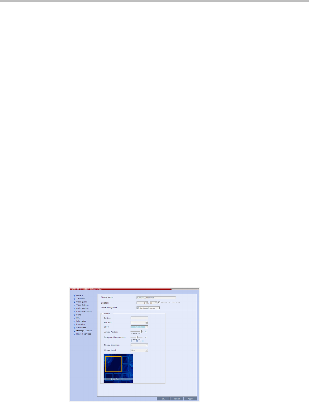
Polycom® RealPresence Collaboration ServerVirtual Edition Administrator’s Guide
12-10 Polycom, Inc.
9Optional. Add a participant to the list of participants to be Auto Scanned:
aClick on the participant’s name in the All Participants list.
bClick the Add button to move the participant to the Scanning Order pane.
10 Optional. Delete a participant from the list of participants to be Auto Scanned:
aClick on a participant’s name in the Scanning Order list.
bClick the Delete button to move the participant back to the All Participants pane.
11 Optional. Add all participants to the list of participants to be Auto Scanned:
—Click the Add All button.
12 Optional. Delete all participant from the list of participants to be Auto Scanned:
—Click the Delete All button.
13 Optional. Move the participant up in the Scanning Order:
—Click the Up button.
14 Optional. Move the participant down in the Scanning Order:
—Click the Down button.
15 Click the Apply button to confirm and keep the Conference Properties dialog box open.
or
Click the OK the button to confirm and return to the Collaboration Server Web Client
Main Screen.
16 Click the Skins tab to view the skin selected for the conference.
You cannot select another skin during an ongoing conference.
17 Click the IVR tab to view the IVR settings.
18 Click the Information tab to view general information defined for the conference.
Changes made to this information once the conference is running are not saved to the
CDR.
19 Click the Recording tab to review the recording settings for the conference.
20 Click the Site Names tab to enable or disable the display of site names during the
conference, and adjust the display properties.
21 Click the Message Overlay tab to send text messages to the conference participants
during the conference, and adjust the display properties of the text messages.
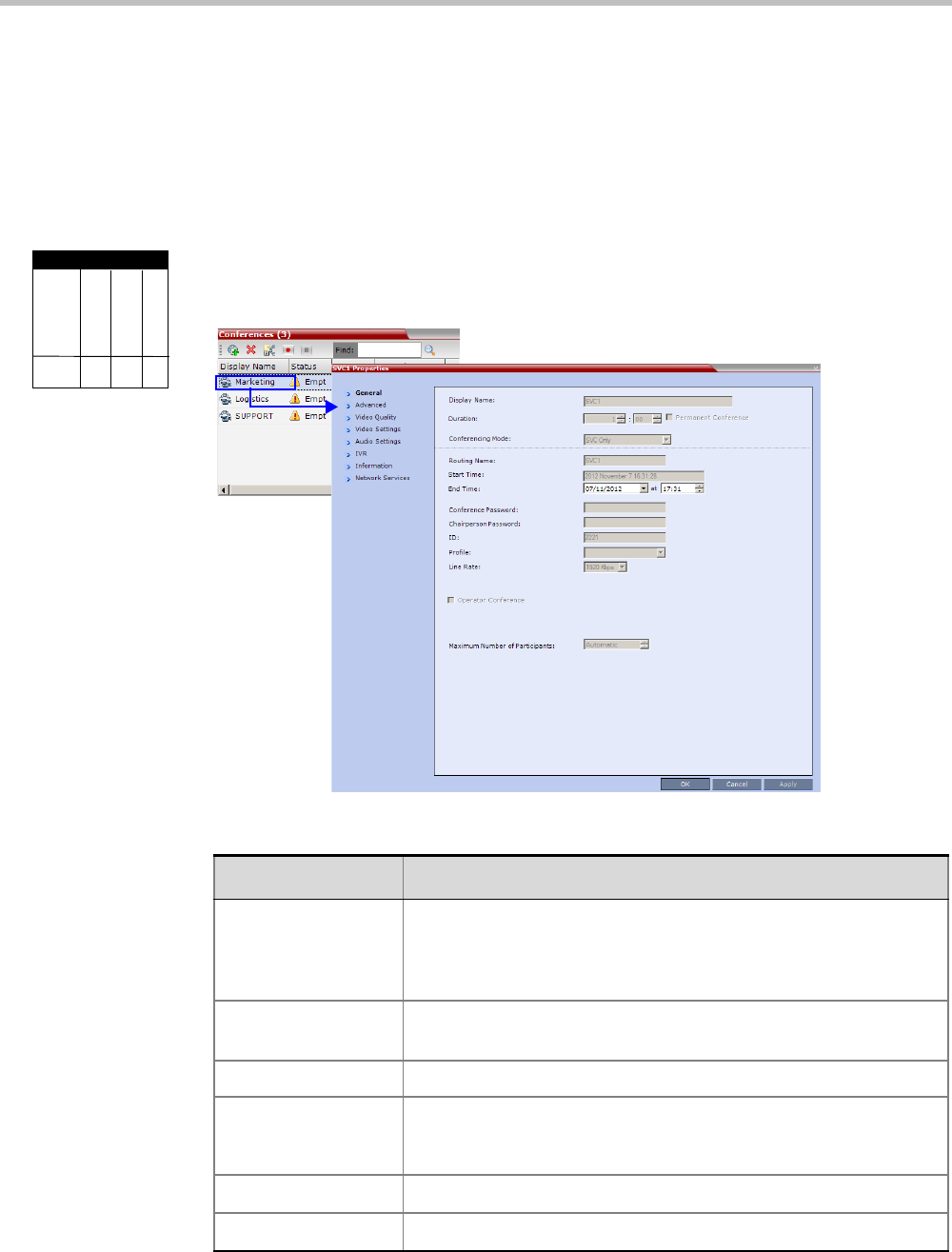
Chapter 12-Conference and Participant Monitoring
Polycom, Inc. 12-11
For more information, see "Message Overlay for Text Messaging” on page 2-58.
22 Click the Network Services tab to verify the SIP registration for the conference.
23 Click OK to close the Conference Properties dialog box.
Viewing the Properties of an Ongoing SVC-based Conference
To view the parameters of an ongoing SVC conference:
1In the Conference list pane, double-click the SVC conference or right-click the SVC
conference and then click Conference Properties.
The Conference Properties - General dialog box with the General tab opens.
2The following information is displayed in the General tab:
Viewing Permissions
Chairperson
Administrator
Operator
Tab
General
Field Description
Display Name The Display Name is the conference name in native language and
Unicode character sets to be displayed in the Collaboration Server
Web Client.
Note: This field is displayed in all tabs.
Duration The expected duration of the conference using the format HH:MM.
Note: This field is displayed in all tabs.
Conferencing Mode The conferencing mode for the conference.
Routing Name The ASCII name of the conference. It can be used by H.323 and SIP
participants for dialing in directly to the conference. It is used to
register the conference in the gatekeeper and the SIP server.
Start Time The time the conference started.
End Time The expected conference end time.
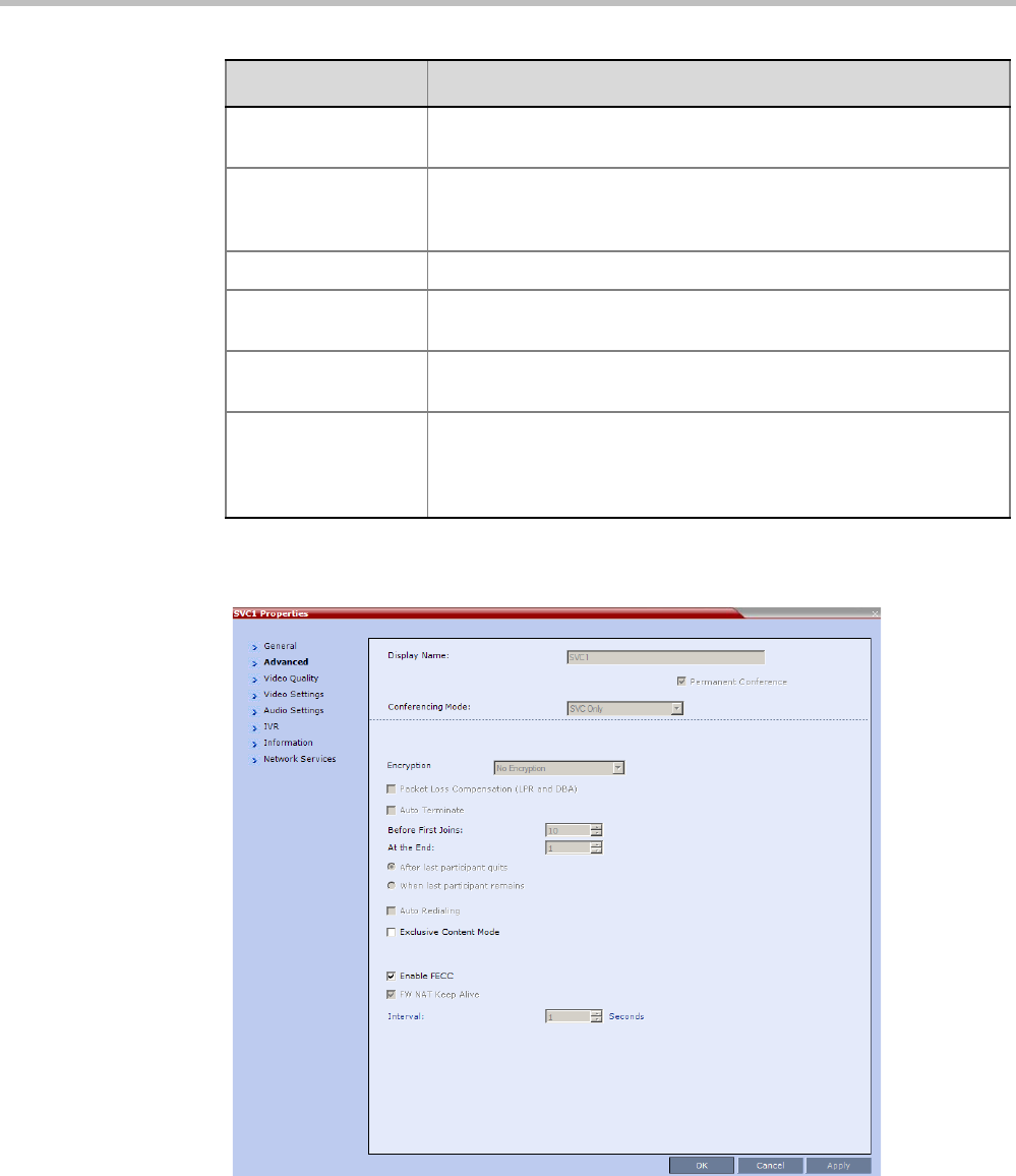
Polycom® RealPresence Collaboration ServerVirtual Edition Administrator’s Guide
12-12 Polycom, Inc.
3Click the Advanced tab.
The Conference Properties - Advanced dialog box opens.
Conference
Password
A numeric password for participants to access the conference.A
numeric password for participants to access the conference.
Chairperson
Password
A numeric password used by participants to identify themselves as
the conference chairperson.A numeric password used by participants
to identify themselves as the conference chairperson.
ID The conference ID.
Profile The name of the conference Profile from which conference
parameters were taken.
Line Rate The maximum transfer rate, in kilobytes per second (Kbps) of the call
(video and audio streams).
Max Number of
Participants
Indicates the total number of participants that can be connected to
the conference. The Automatic setting indicates the maximum
number of participants that can be connected to the MCU according
to resource availability.
Field Description
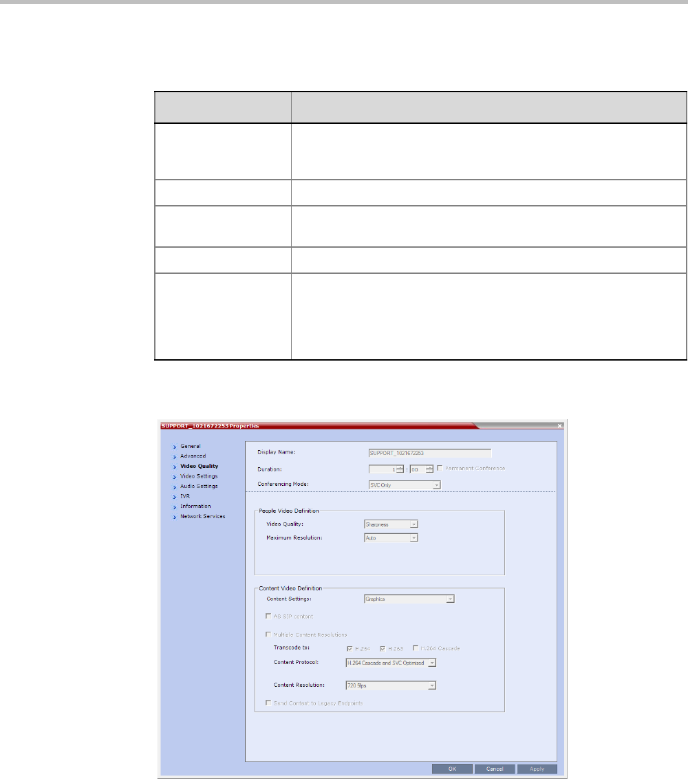
Chapter 12-Conference and Participant Monitoring
Polycom, Inc. 12-13
4The following information is displayed in the Advanced tab:
5Click the Video Quality tab.
The Conference Properties - Video Quality dialog box opens.
Table 12-6 Conference Properties - Advanced Parameters
Field/Option Description
Auto Terminate When selected, indicates that the MCU will automatically terminate
the conference when Before First Joins, At the End-After Last Quits
and At the End - When Last Participant Remains parameters apply.
Auto Redialing Dial-out is not supported in SVC conferences.
Exclusive Content
Mode
When selected, Content is limited to one participant.
Enable FECC Far End Camera Control is not supported in SVC conferences.
FW NAT Keep Alive When selected, sends a FW NAT Keep Alive message at specific
Intervals for the RTP, UDP and BFCP channels. The interval specifies
how often a FW NAT Keep Alive message is sent. For more
information, see "RealPresence Collaboration Server Virtual Edition
Network Port Usage” on page 15-28.

Polycom® RealPresence Collaboration ServerVirtual Edition Administrator’s Guide
12-14 Polycom, Inc.
The following information is displayed:
Table 12-7 Conference Properties - Video Quality Parameters
Field/Option Description
People Video Definition
Video Quality Indicates the resolution and frame rate that determine the video
quality set for the conference. Only Sharpness is supported.
Maximum Resolution In SVC conferencing, this is always Auto (default) - The Maximum
Resolution remains as selected in the Resolution Configuration dialog
box.
Content Video Definition
AS-SIP AS-SIP This option is not supported with RealPresence
Collaboration Server Virtual Edition.is not supported in SVC
conferences.
Multiple Content
Resolutions
Multiple Content Resolutions This option is not supported with
RealPresence Collaboration Server Virtual Edition.This option is not
supported with RealPresence Collaboration Server Virtual Edition.is
not supported in SVC conferences.
Content Settings In SVC conferencing, this is always set to Graphics
Content Protocol In SVC conferencing this is always set to H.264 Cascade and SVC
Optimized.
Content Resolution Resolution is fixed in SVC conferences.
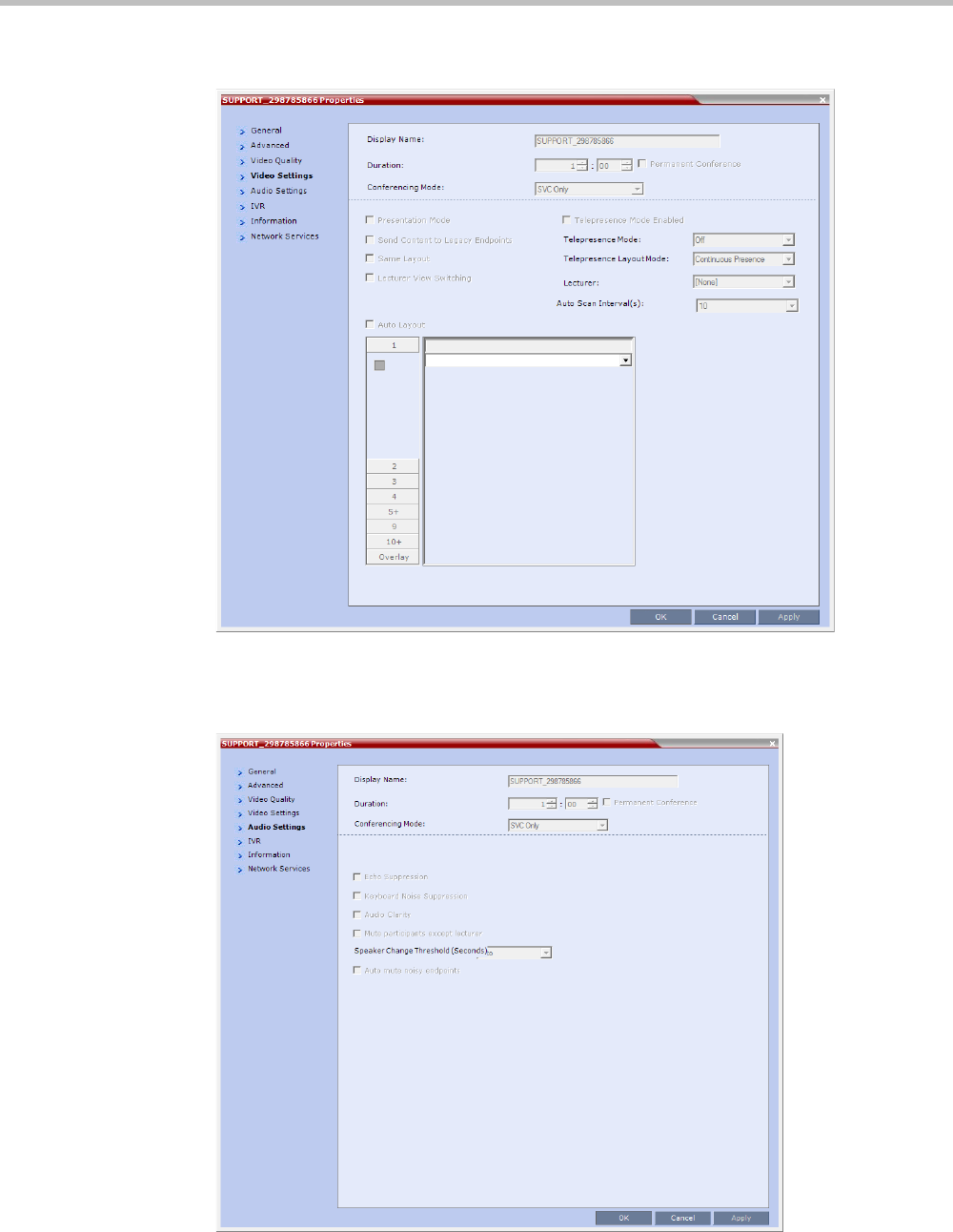
Chapter 12-Conference and Participant Monitoring
Polycom, Inc. 12-15
6Click the Video Settings tab to view the video parameters defined for the conference.
In SVC conferences, only Auto Layout is enabled and cannot be disabled. All other
video settings are disabled.
7Click the Audio Settings tab to view the audio parameters defined for the conference.
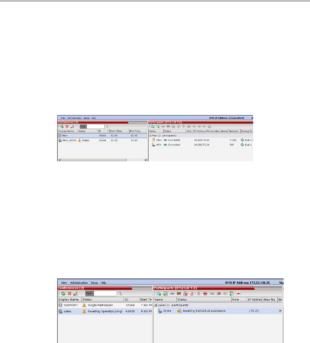
Polycom® RealPresence Collaboration ServerVirtual Edition Administrator’s Guide
12-16 Polycom, Inc.
In SVC conferences, all Audio Settings options are disabled.
8Click the Information tab to view general information defined for the conference.
Changes made to this information once the conference is running are not saved to the
CDR.
9Click OK to close the Conference Properties dialog box.
Monitoring Operator Conferences and Participants Requiring Assistance
(CP and Mixed CP and SVC Conferences)
Operator conferences are monitored in the same way as standard ongoing conferences.
Each Operator conference includes at least one participant - the Operator.
You can view the properties of the Operator conference by double-clicking the conference
entry in the Conferences list or by right-clicking the conference entry and selecting
Conference Properties. For more information, see the Polycom® RealPresence Collaboration
Server Virtual Edition Getting Started Guide, "Conference Level Monitoring” on page 3-45.
Requesting Help
A participant can request help using the appropriate DTMF code from his/her touch tone
telephone or the endpoint’s DTMF input device. The participant can request Individual
Assistance (default DTMF code *0) or Conference Assistance (default DTMF code 00).
Participants in Entry Queues who failed to enter the correct destination conference ID or the
conference password will wait for operator assistance (provided that an Operator
conference is active).
When requiring or requesting operator assistance, the Collaboration Server management
application displays the following:
• The participant’s connection Status changes, reflecting the help request. For details, see
Table 12-8.
• The conference status changes and it is displayed with the exclamation point icon and
the status “Awaiting Operator”.
• The appropriate voice message is played to the relevant participants indicating that
assistance will be provided shortly.
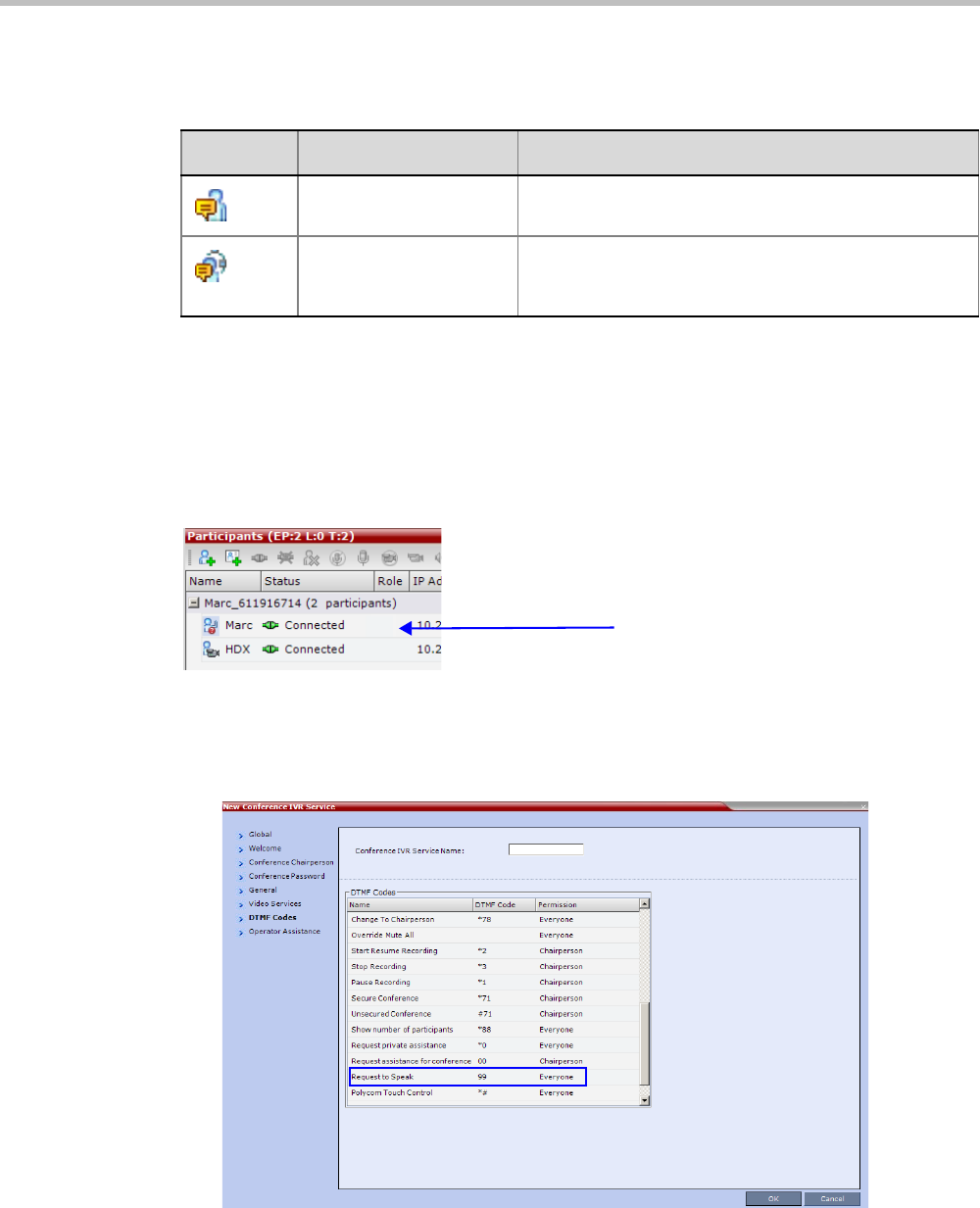
Chapter 12-Conference and Participant Monitoring
Polycom, Inc. 12-17
The following icons and statuses are displayed in the Participant Status column:
When the Operator moves the participant to the Operator conference for individual assistance
the participant Status indications are cleared.
Request to Speak
Participants that were muted by the conference organizer/system operator can indicate that
they want to be unmuted by entering the appropriate DTMF code.
An icon is displayed in the Role column of the Participants list for 30 seconds.
Request to Speak is:
• Activated when the participant enters the appropriate DTMF code (default: 99).
The DTMF code can be modified in the conference IVR Service Properties - DTMF Codes
dialog box.
• Available for dial-in and dial-out participants.
• A participant can request to speak more than once during the conference.
Table 12-8 Participants List Status Column Icons and Indications
Icon Status indication Description
Awaiting Individual
Assistance
The participant has requested the operator’s assistance
for himself/herself.
Awaiting Conference
Assistance
The participant has requested the operator’s assistance
for the conference. Usually this means that the operator
is requested to join the conference.
Request to Speak
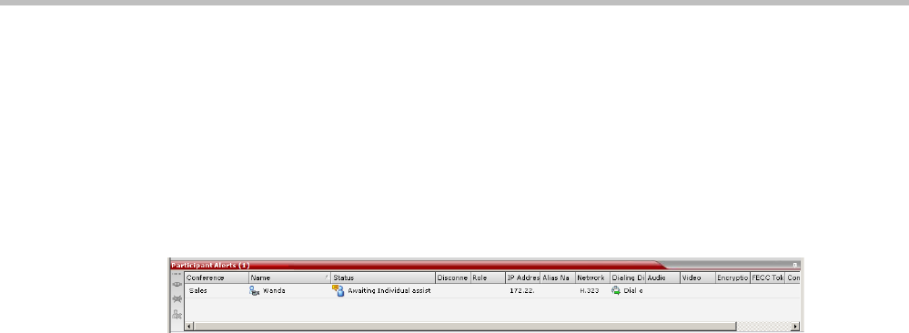
Polycom® RealPresence Collaboration ServerVirtual Edition Administrator’s Guide
12-18 Polycom, Inc.
•Supported in all conference types.
• Supported in H.323 and SIP environments.
• The duration of the icon display cannot be modified.
Participant Alerts List
The Participant Alerts list contains all the participants who are currently waiting for operator
assistance.
Participants are automatically added to the Participants Alerts list in the following
circumstances:
• The participant fails to connect to the conference by entering the wrong conference ID
or conference password and waits for the operator’s assistance.
• The participant requests Operator’s Assistance during the ongoing conference.
This list is used as reference only. Participants can be assisted and moved to the Operator
conference or the destination conference only from the Participants list of the Entry Queues or
ongoing conference where they are awaiting assistance.
The participants are automatically removed from the Participant Alerts list when moved to
any conference (including the Operator conference).
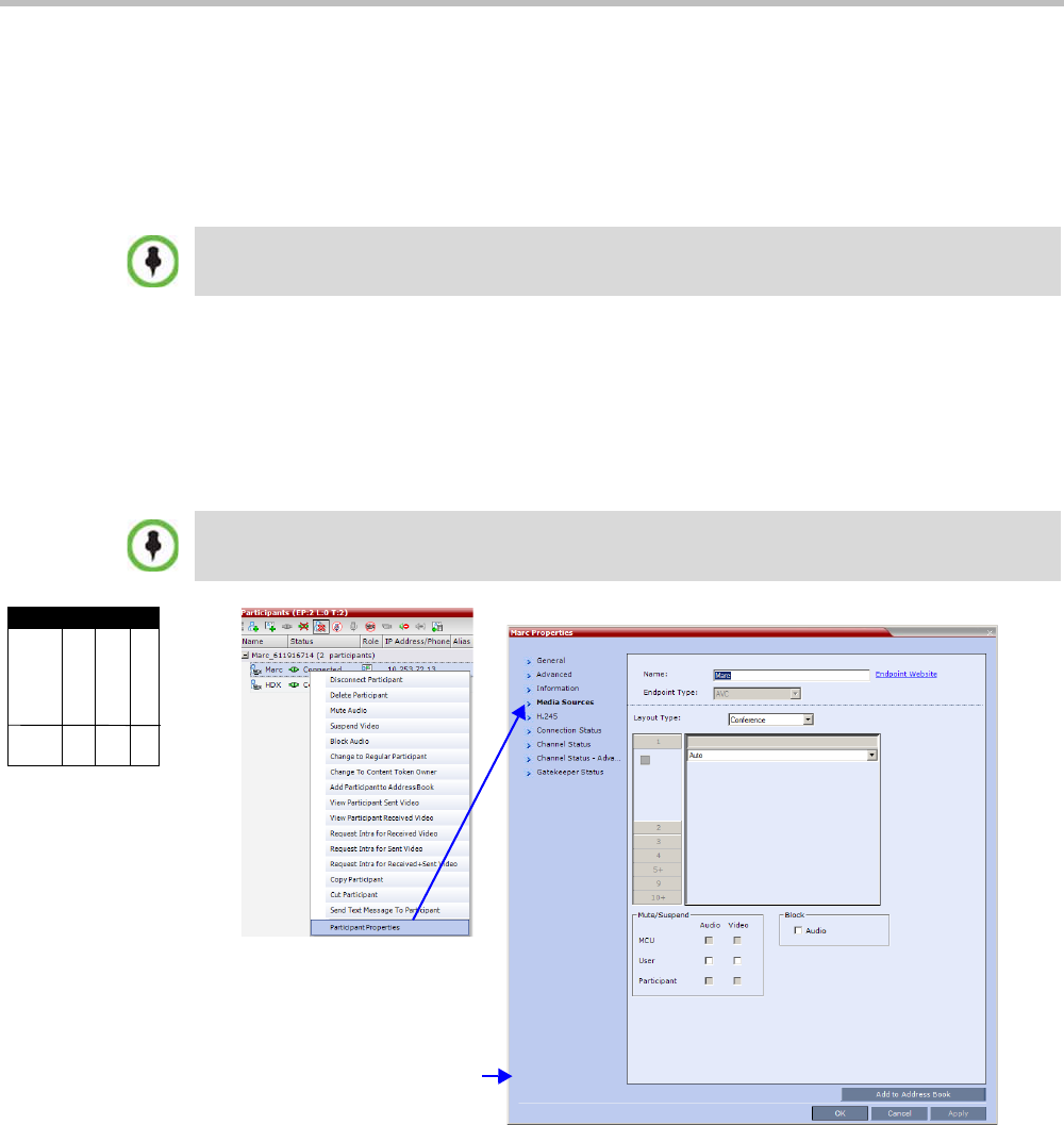
Chapter 12-Conference and Participant Monitoring
Polycom, Inc. 12-19
Participant Level Monitoring
In addition to conference information, you can view detailed information regarding the
status and parameters of each listed participant, using the Participant Properties dialog box.
Participant properties can be displayed for all participants currently connected to a
conference and for defined participants that have been disconnected.
Displaying Participants Properties
To display the participant Properties:
1In the Participant List pane double-click the participant entry. Alternatively, right-click a
participant and then click Participant Properties.
The Participant Properties - Media Sources dialog box opens.
The Media Sources dialog box enables you to mute participant’s audio, suspend
participant’s video transmission and select a personal Video Layout for the participant.
SIP SVC-based participant properties are similar to SIP AVC-based participant properties.
Media Sources properties are not available for SVC participants.
Viewing Permissions
Chairperson
Administrator
Operator
Tab
Media
Sources
AVC-based
Participant

Polycom® RealPresence Collaboration ServerVirtual Edition Administrator’s Guide
12-20 Polycom, Inc.
IP Participant Properties
The following parameters are displayed for an IP participant
Table 12-9 Participant Properties - Media Sources Parameters
Field Description
Name Indicates the participant’s name.
Note: This field is displayed in all tabs.
Endpoint Website
(link)
Click the Endpoint Website hyperlink to connect to the internal website of
the participant’s endpoint. It enables you to perform administrative,
configuration and troubleshooting activities on the endpoint.
The connection is available only if the IP address of the endpoint’s internal
site is filled in the Website IP Address field in the Participant Properties -
General dialog box.
Note: This field is displayed in all tabs.
Endpoint Type Indicates whether the participant is using an AVC-based or SVC-based
endpoint.
Fields, tabs and options are enabled or disabled according to the endpoint
type.
Note: This field is displayed in all tabs.
Layout Type Indicates whether the video layout currently viewed by the participant is the
Conference or Personal Layout. If Personal Layout is selected, you can
select a Video Layout that will be viewed only by this participant.
Video Layout Indicates the video layout currently viewed by the participant. When
Personal Layout is selected in the Layout Type you can force participants
to the video windows in a layout that is specific to the participant. For more
information, see Polycom® RealPresence Collaboration Server Virtual
Edition Getting Started Guide, "Changing the Video Layout of a
Conference (AVC-Based CP and Mixed CP and SVC Conferences)” on
page 3-59.
Mute/Suspend Indicates if the endpoint’s audio and/or video channels have been muted/
suspended. The entity that initiated audio mute or video suspend is also
indicated.
•MCU – Audio or Video channel has been muted/suspended by the
MCU.
•User – Channels have been muted/suspended by the Collaboration
Server user.
•Participant – Channels have been muted/suspended by the
participant from the endpoint.
You can also cancel or perform mute and suspend operation using these
check boxes.
Note: If the participant muted his/her audio channel, the system displays
the mute icon only for H.323. This icon is not displayed for SIP participant
due to SIP standard limitation.
Block When checked, the audio transmission from the conference to the
participant’s endpoint is blocked, but the participant will still be heard by
other participants.
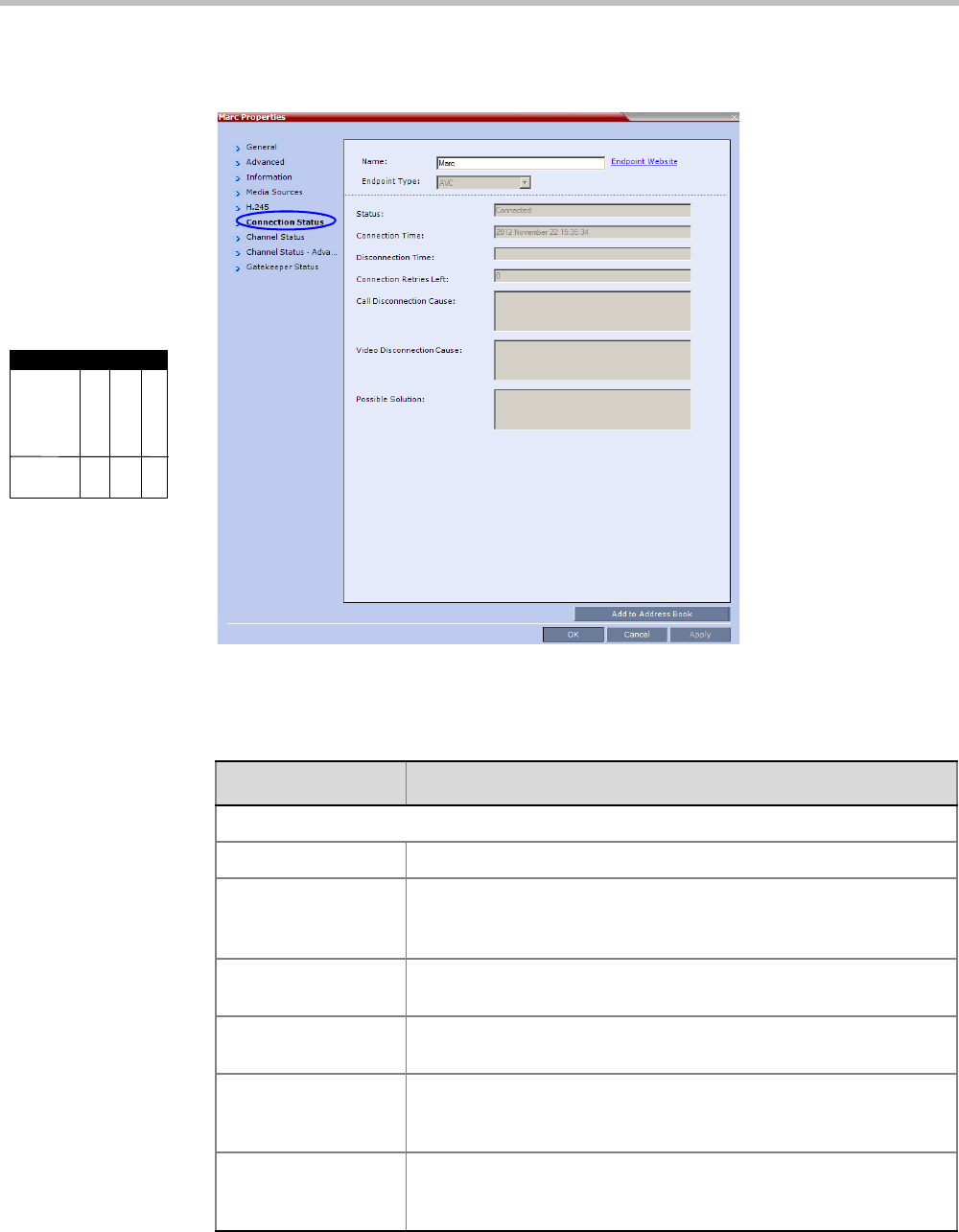
Chapter 12-Conference and Participant Monitoring
Polycom, Inc. 12-21
2Click the Connection Status tab to view the connection status, and if disconnected the
cause of the disconnection.
This dialog box is the same for AVC-based and SVC-based participants.
The following parameters are displayed:
Viewing Permissions
Chairperson
Administrator
Operator
Tab
Connection
Status
Table 12-10 Participant Properties - Connection Status Parameters
Field Description
Participant Status
Status Indicates the connection status of the participant.
Connection Time The date and time the participant connected to the conference.
Note: The time format is derived from the MCU’s operating system
time format.
Disconnection Time The date and time the defined participant disconnected from the
conference.
Connection Retries
Left
Indicates the number of retries left for the system to connect defined
participant to the conference.
Call Disconnection
Cause
Displays the cause for the defined participant’s disconnection from
the conference. See Appendix A: "Disconnection Causes” on
page A-1.
Video Disconnection
Cause
Displays the cause the video channel could not be connected. For
more information, see Appendix A: "Disconnection Causes” on
page A-1.
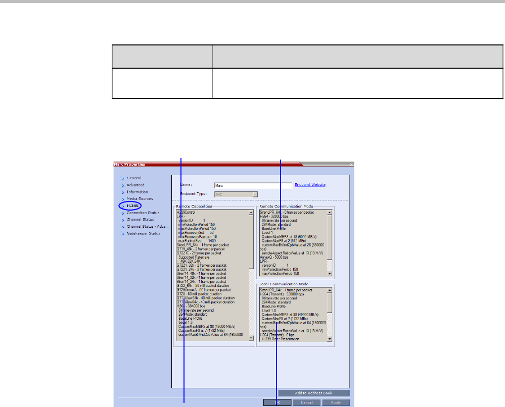
Polycom® RealPresence Collaboration ServerVirtual Edition Administrator’s Guide
12-22 Polycom, Inc.
3Click the H.245 (H.323) or SDP (SIP) tab during or after the participant’s connection
process to view information that can help in resolving connection issues.
Possible Solution In some cases, a possible solution is indicated to the cause of the
video disconnection.
Table 12-10 Participant Properties - Connection Status Parameters (Continued)
Field Description
Displays the endpoint’s actual
capabilities used for the connection
Displays the MCU’s capabilities used for
connection with the participant
List’s the endpoint’s capabilities as
retrieved from the remote site
LPR activity
(Displayed in all three panes)
H.323 Participant
(AVC-based|)
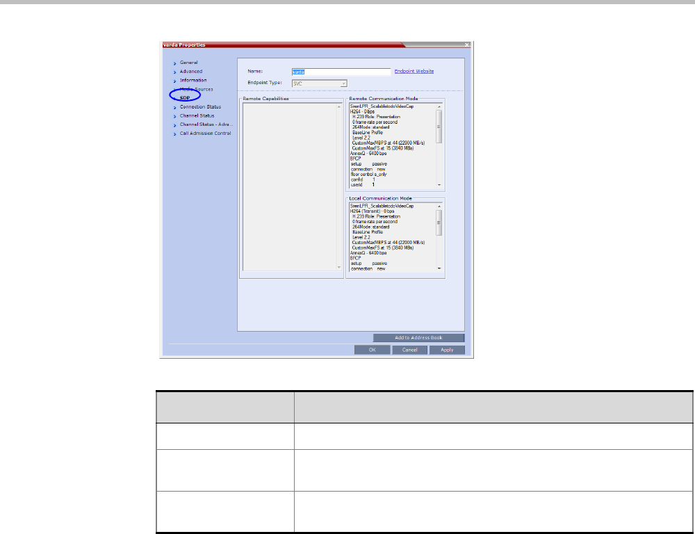
Chapter 12-Conference and Participant Monitoring
Polycom, Inc. 12-23
Table 12-11 Participant Properties - H.245/SDP Parameters
Field Description
Remote Capabilities Lists the participant’s capabilities as declared by the endpoint.
Remote
Communication Mode
Displays the actual capabilities used by the endpoint when
establishing the connection with the MCU (Endpoint to MCU).
Local Communication
Mode
Displays the actual capabilities used by the MCU when establishing
the connection with the participant’s endpoint (MCU to Endpoint).
SIP Participant
(AVC-based and
SVC-based)
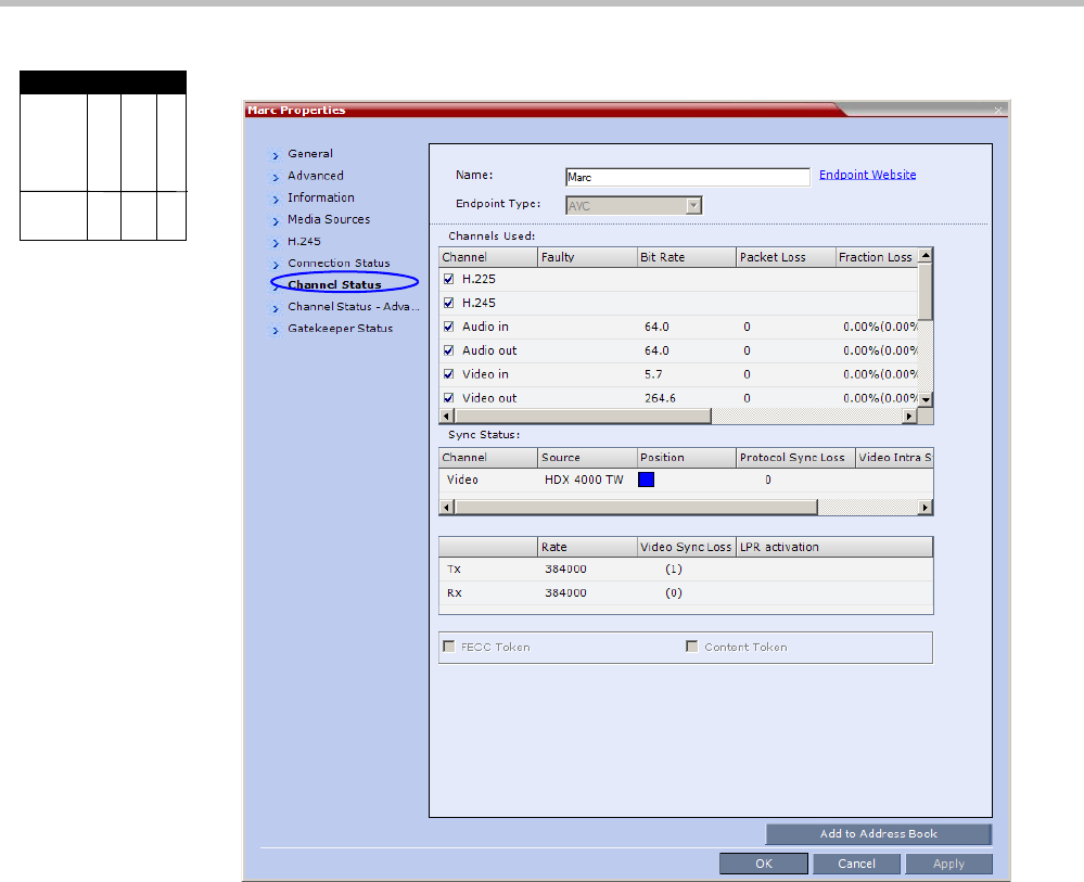
Polycom® RealPresence Collaboration ServerVirtual Edition Administrator’s Guide
12-24 Polycom, Inc.
4Click on the Channel Status tab to view the status of the various channels.
Viewing Permissions
Chairperson
Administrator
Operator
Tab
Channel
Status

Chapter 12-Conference and Participant Monitoring
Polycom, Inc. 12-25
The following parameters are displayed:
Table 12-12 Participant Properties - Channel Status Parameters
Field Description
Channels Used When checked, indicates the channel type used by the participant to
connect to the conference: Incoming channels are endpoint to MCU,
Outgoing channels are from MCU to endpoint.
Channels:
•H.225/Signaling - The call-signaling channel.
•H.245/SDP - The Control channel.
•Audio in - Incoming audio channel
•Audio out - Outgoing audio channel
•Video in - Incoming video channel
•Video out - Outgoing video channel
•Content in - H.239/People+Content conferences
•Content out - H.239/People+Content conferences
•FECC in - The incoming FECC channel is open.
•FECC out - The outgoing FECC channel is open.
Columns:
•Faulty – A red exclamation point indicates a faulty channel
condition. This is a real-time indication; when resolved the
indication disappears. An exclamation point indicates that further
investigation may be required using additional parameters
displayed in the Advanced Channel Status tab.
•Bit Rate – The actual transfer rate for the channel. When
channel is inactive, bit rate value is 0. For example, if the
participant is connected without video, the bit rate for the video
channel is 0.
Note: The CTS Audio Auxiliary channel is used only for Content.
In all other cases, the bit rate shown in this column for this
channel is 0.
•Packet Loss – The accumulated count of all packets that are
missing according to the RTCP report since the channel was
opened. This field is relevant only during the connection stage
and does not display faulty indications.
•Fraction Loss (Peak) – The ratio between the number of lost
packets and the total number of transmitted packets since the
last RTCP report. Peak (in parentheses) indicates the highest
ratio recorded since the channel was opened.
•Number of Packets – The number of received or transmitted
packets since the channel has opened. This field does not cause
the display of the faulty indicator.
•Jitter (Peak) – Displays the network jitter (the deviation in time
between the packets) as reported in the last RTCP report (in
milliseconds). Peak (in parentheses) reflects the maximum
network jitter since the channel was opened.
•Latency – Indicates the time it takes a packet to travel from one
end to another in milliseconds (derived from the RTCP report).
High latency value may indicate that there is a problem in the
network, or that the endpoint is sending an incorrect RTCP
values.

Polycom® RealPresence Collaboration ServerVirtual Edition Administrator’s Guide
12-26 Polycom, Inc.
Sync Status Channel - The channel type: Video or Content.
Source - The name of the participant currently viewed by this
participant.
Position - The video layout position indicating the place of each
participant as they appear in a conference.
Protocol Sync Loss - Indicates whether the system was able to
synchronize the bits order according to the selected video protocol.
Video Intra Sync - Indicates whether the synchronization on a video
Intra frame was successful.
Video Resolution - The video resolution of the participant.
Rx - Rate The received line rate.
Tx - Rate The transmitted line rate.
Tx - Video Sync Loss When checked, indicates a video synchronization problem in the
outgoing channel from the MCU.
The counter indicates the sync-loss count.
Rx - Video Sync Loss When checked, indicates a video synchronization problem in the
incoming channel from the endpoint.
The counter indicates the sync-loss count.
Tx - LPR Activation When checked, indicates LPR activation in the outgoing channel.
Rx - LPR Activation When checked, indicates LPR activation in the incoming channel.
FECC Token When checked, indicates that the participant is the holder of the
FECC Token.
Content Token When checked, indicates that the participant is the holder of the
Content Token.
Table 12-12 Participant Properties - Channel Status Parameters (Continued)
Field Description
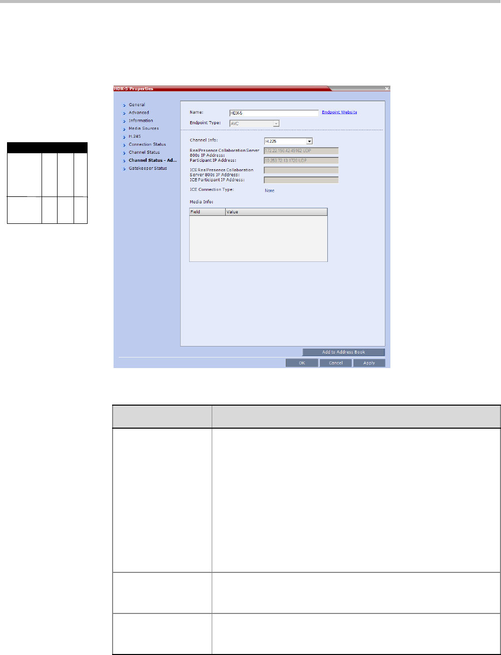
Chapter 12-Conference and Participant Monitoring
Polycom, Inc. 12-27
5Click the Channel Status Advanced tab to view additional information for selected
audio and video channels.
In the Channel Status - Advanced tab, channels can be selected for viewing additional
information:
Viewing Permissions
Chairperson
Administrator
Operator
Tab
Channel
Status
Advanced
Table 12-13 Participant Properties - Channel Status Advanced Parameters
Field Description
Channel Info Select a channel to view its information:
•H.225
•H.245
•Audio in
•Audio out
•Video in
•Video out
•Content in
•Content Out
•SIP BFCP TCP
Collaboration Server
IP Address
The IP address and the transport protocol (TCP/UDP) of the MCU to
which the participant is connected and the port number allocated to
the participant incoming media stream on the MCU side.
Participant IP
Address
The IP address and the transport protocol (TCP/UDP) of the
participant and the port number allocated to the media stream on the
participant side.

Polycom® RealPresence Collaboration ServerVirtual Edition Administrator’s Guide
12-28 Polycom, Inc.
ICE RealPresence
Collaboration Server
Virtual Edition IP
Address
Not Supported with RealPresence Collaboration Server.
ICE Participant IP
Address
Not Supported with RealPresence Collaboration Server..
ICE Connection Type •Not Supported with RealPresence Collaboration Server.
Media Info This table provides information about the audio and video parameters,
such as video algorithm, resolution, etc. For more information, see
Appendix E: "Participant Properties Advanced Channel Information”
on page E-1.
RTP Statistics This information may indicate problems with the network which can
affect the audio and video quality. For more information, see Appendix
E: "Participant Properties Advanced Channel Information” on
page E-1.
Table 12-13 Participant Properties - Channel Status Advanced Parameters (Continued)
Field Description
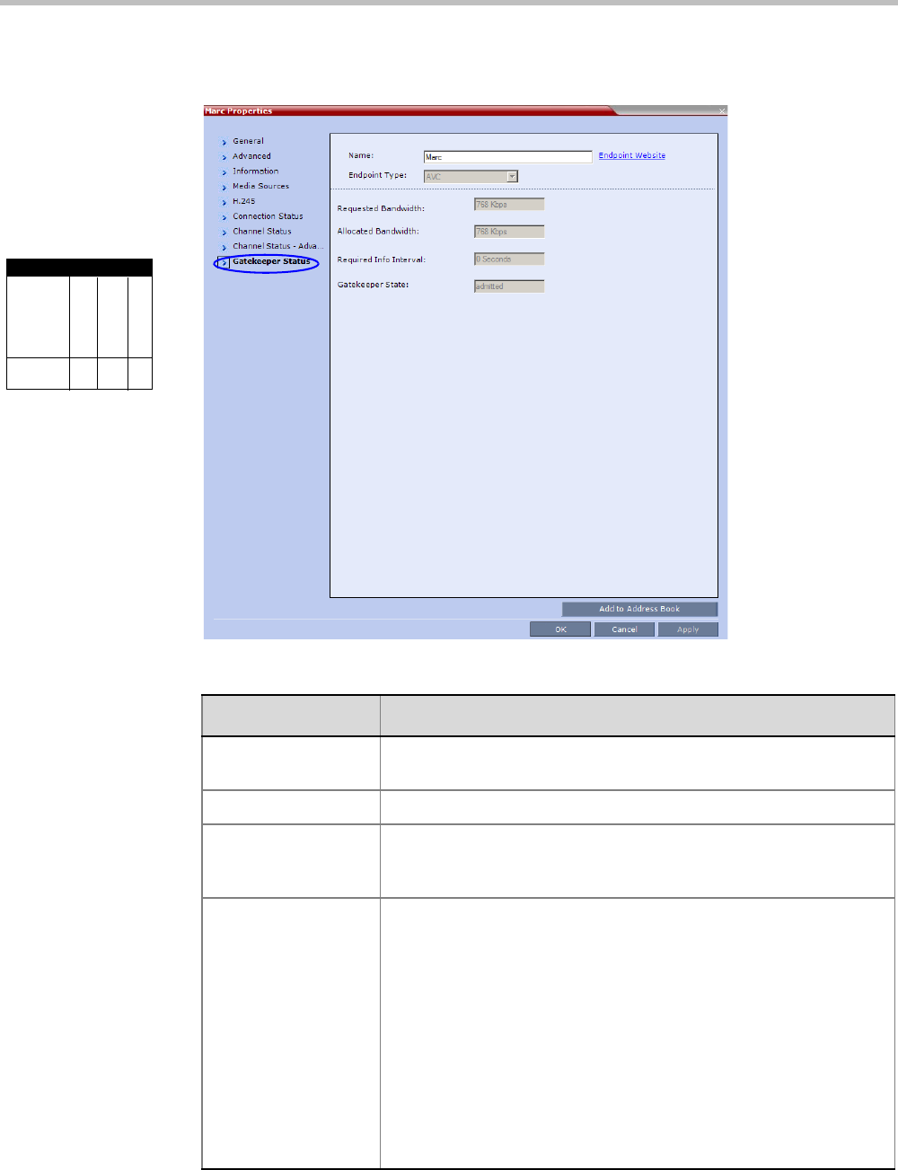
Chapter 12-Conference and Participant Monitoring
Polycom, Inc. 12-29
6Optional for H.323 AVC-based participants. Click the Gatekeeper Status tab to view
its parameters.
Viewing Permissions
Chairperson
Administrator
Operator
Tab
Gatekeeper
Status
Table 12-14 Participant Properties - Gatekeeper Status Parameters
Field Description
Requested
Bandwidth
The bandwidth requested by the MCU from the gatekeeper.
Allocated Bandwidth The actual bandwidth allocated by the gatekeeper to the MCU.
Required Info Interval Indicates the interval, in seconds, between registration messages
that the MCU sends to the gatekeeper to indicate that it is still
connected.
Gatekeeper State Indicates the status of the participant’s registration with the
gatekeeper and the bandwidth allocated to the participant. The
following statuses may be displayed:
•ARQ – Admission Request - indicates that the participant has
requested the gatekeeper to allocate the required bandwidth on
the LAN.
•Admitted – indicates that the gatekeeper has allocated the
required bandwidth to the participant.
•DRQ – Disengage Request – the endpoint informs the gatekeeper
that the connection to the conference is terminated and requests
to disconnect the call and free the resources.
•None – indicates that there is no connection to the gatekeeper.
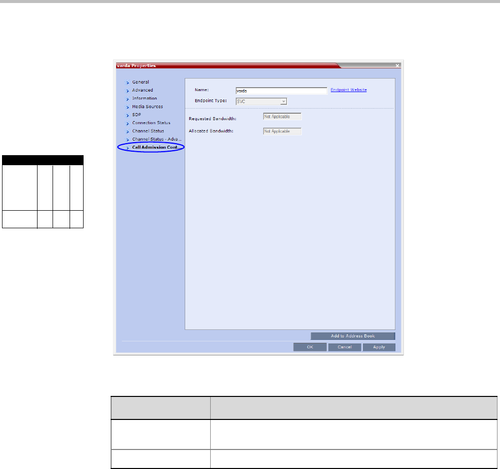
Polycom® RealPresence Collaboration ServerVirtual Edition Administrator’s Guide
12-30 Polycom, Inc.
7Optional for SIP AVC-based and SVC-based participants. Click the Call Admission
Control tab to view its parameters.
Viewing Permissions
Chairperson
Administrator
Operator
Tab
Gatekeeper
Status
Table 12-15 Participant Properties - Gatekeeper Status Parameters
Field Description
Requested
Bandwidth
The bandwidth requested by the MCU from the SIP server.
Allocated Bandwidth The actual bandwidth allocated by the SIP server to the MCU.
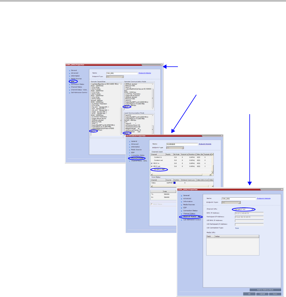
Chapter 12-Conference and Participant Monitoring
Polycom, Inc. 12-31
Monitoring SIP BFCP Content
In the SIP Participant Properties dialog box, BFCP status information appears in:
• All three panes of the SDP tab.
•The Channel Status tab.
•The Channel Status -Advanced tab.
For more information see "Participant Level Monitoring” on page 12-19.
SDP
Channel Status
Channel Status - Advanced

Polycom® RealPresence Collaboration ServerVirtual Edition Administrator’s Guide
12-32 Polycom, Inc.
Detecting SIP Endpoint Disconnection
When an abnormal disconnection of SIP endpoints occurs because of network problems or
client application failures, SIP endpoints remain connected to the conference causing
connection disruptions. For example, the video freezes in the layout or blocks content for
SIP endpoints when a quick re-connection is performed. It can take several minutes to detect
the SIP endpoint disconnection using the SIP standard behavior.
In a normal SIP video call, audio and video (RTP and RTCP) messages are sent from the
endpoints to the MCU to detect the signaling of connected endpoints. Conversely, SVC
endpoints might not send video RTP messages to the MCU when a participant is not
displayed in the video layout of any of the participants in the conference. For SVC
endpoints, the MCU will only verify audio RTP and RTCP messages and video RTCP
messages. Video RTP messages will not be checked.
To detect the disconnection of SIP endpoints in a reasonable amount of time, a new system
flag can be defined to specify the amount of time that the MCU should wait for an RTCP or
RTP message from the SIP endpoint before the endpoint starts the disconnection process.
The system default value is automatically set to 20 seconds.
The system flag, DETECT_SIP_EP_DISCONNECT _TIMER, contains the amount of time in
seconds to wait for an RTCP or RTP message to be received from the endpoint. When the
time that was set in the system flag has elapsed and no RTCP or RTP audio or video
message has been received on either the audio or the video channel, the MCU disconnects
the SIP endpoint from the conference. A CDR event record is created with a Call
Disconnection Cause of “SIP remote stopped responding”.
The Microsoft Lync add-in endpoint opens audio and content channels. Lync endpoints can
send RTCP/RTP messages and empty RTP audio messages. When the time that was set in
the system flag has elapsed and no RTCP or RTP message has been received on the audio
channel, the MCU disconnects the endpoint from the conference.
SIP audio only endpoints use the audio channel only. When the time that was set in the
system flag has elapsed and no RTCP or RTP message has been received on the audio
channel, the MCU disconnects the SIP audio endpoint from the conference.
Configuring the System Flag
When you want to change the system default value of 20 seconds, the system flag,
DETECT_SIP_EP_DISCONNECT_TIMER, can be manually added to the System Flags
configuration to detect the disconnection of SIP endpoints. For more information see
"Manually Adding and Deleting System Flags” on page 20-12.
The value range is from 0 to 300 seconds. When the value is set between 0 and 14, the feature
is disabled and SIP endpoints are not detected for disconnection. When the value is set
between 15 and 300, the feature is enabled.

Polycom, Inc. 13-1
13
Recording Conferences
Conferences running on the Collaboration Server can be recorded using a Polycom® RSS™
Recording and Streaming Server (RSS).
The recording system can be installed at the same site as the conferencing MCU or at a
remote site. Several MCU’s can share the same recording system.
Recording conferences is enabled via a Recording Link, which is a dial-out connection from
the conference to the recording system.
Recording can start automatically, when the first participant connects to a conference, or on
request, when the Collaboration Server user or conference chairperson initiates it.
Multiple Recording Links may be defined.
Conference Recording Links can be associated on the Collaboration Server with Virtual Recording
Rooms (VRR), created and saved on the Polycom® RSS™ 4000 Version 8.5 Recording and
Streaming Server (RSS).
Each Recording Link defined on the Collaboration Server can be given a descriptive name and
can be associated with one VRR saved on the Polycom RSS 4000.
The following guidelines apply:
•A Recording Link that is being used by an ongoing conference cannot be deleted.
•A Recording Link that is assigned to a Profile cannot be deleted.
•The Recording Link supports H.264 High Profile with H.323 connections.
•While a Profile is being used in an ongoing conference, it cannot have a different
Recording Link assigned to it.
• Up to 100 Recording Links can be listed for selection in the Conference Profile.
•Multiple Recording Links are supported in Continuous Presence and Video Switched
conferences.
• The number of Recording Links available for selection is determined by the value of the
MAXIMUM_RECORDING_LINKS System Flag in system.cfg. Default value is 20
Recording Links.
• The recording link can be encrypted when recording from an encrypted conference to
the RSS that is set to encryption. For more details, see "Recording Link Encryption” on
page 13-7.
Conference recording is not available in SVC Conferencing Mode.

Polycom® RealPresence Collaboration ServerVirtual Edition Administrator’s Guide
13-2 Polycom, Inc.
Creating Multiple Virtual Recording Rooms on the RSS
If the environment includes a Polycom® RSS™ 4000 Version 8.5 Recording and Streaming
Server (RSS) and you want to associate Recording Links on the Collaboration Server with
Virtual Recording Rooms (VRR), created and saved on the Polycom® RSS™ 4000 Version 8.5
perform the following operations on the RSS:
1Modify the parameters of a recording Template to meet the recording requirements.
2Assign the modified recording Template to a VRR. The recording and streaming server
will assign a number to the VRR.
3Repeat Step 1 and Step 2 for each VRR to create additional VRRs.
For more information see the RSS 4000 User Guide.
Configuring the Collaboration Server to Enable Recording
To make recording possible the following components you must be configured on the
Collaboration Server:
•Recording Link – defines the connection between the conference and the recording
system.
•Recording-enabled Conference IVR Service – recording DTMF codes and messages must be
set in the Conference IVR Service to enable “recording-related” voice messages to be
played and to allow the conference chairperson to control the recording process using
DTMF codes.
•Recording-enabled Profile – recording must be enabled in the Conference Profile assigned to
the recorded conference.
If Multiple Recording Links are being defined for Virtual Recording Rooms (VRRs), created and
saved on the Polycom® RSS™ 4000 Version 8.5, the MAXIMUM_RECORDING_LINKS
System Flag in system.cfg can be modified to determine the number of Recording Links
available for selection.
•Range: 20 - 100
•Default: 20
The flag value can be modified by selecting the System Configuration option from the Setup
menu. For more information, see "Modifying System Flags” on page 20-1.
Defining the Recording Link
The Recording Link is defined once and can be updated when the H.323 alias or the IP
address (of the recording system) is changed. Only one Recording Link can be defined in the
Collaboration Server. Its type must be H.323.
To define a Recording Link:
1In the Collaboration Server Management pane, click Recording Links ().
2In the Recording Links list, click the New Recording Link ( ) button.
In Multiple Networks Configuration, Recording Links use the default Network Service to connect to
conferences, therefore the recording system must be defined on the default IP Network Service to
enable the recording.
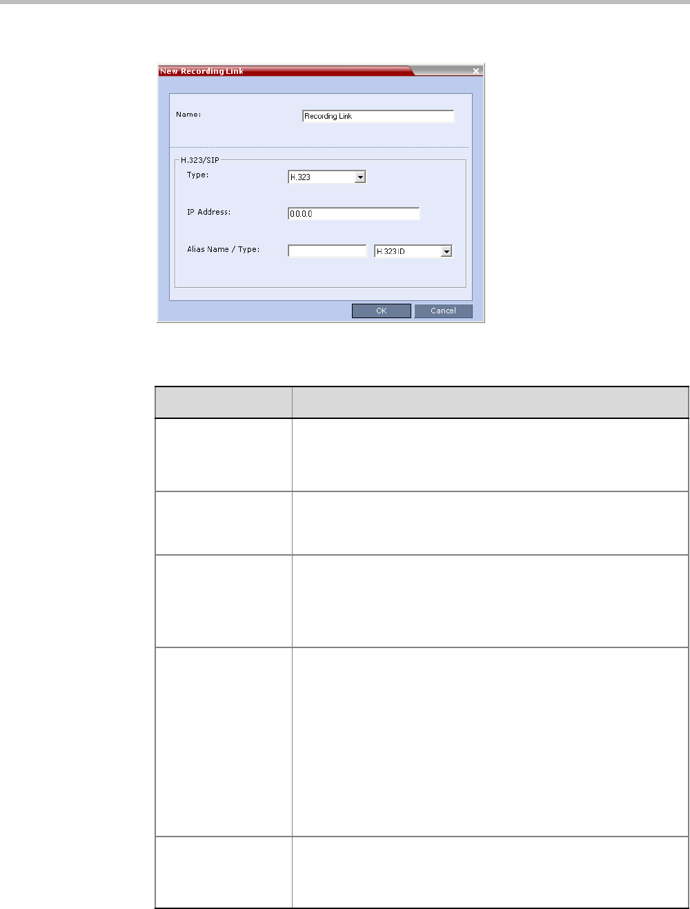
Chapter 13-Recording Conferences
Polycom, Inc. 13-3
The New Recording Link dialog box is displayed.
3Define the following parameters:
Table 13-1 Recording Link Parameters
Parameter Description
Name Displays the default name that is assigned to the Recording Link.
If multiple Recording Links are defined, it is recommended to use a
descriptive name to be indicate the VRR to which it will be associated.
Default: Recording Link
Type Select the network environment:
•H.323
•SIP
IP Address •If no gatekeeper is configured, enter the IP Address of the RSS.
Example: If the RSS IP address is 173.26.120.2 enter
173.26.120.2.
•If a gatekeeper is configured, you can either enter the IP address
or an alias (see the alias description).
Alias Name If using the endpoint’s alias instead of IP address, first select the alias
type and then enter the endpoint’s alias.
If you are associating this recording link to a VRR on the RSS, define
the alias as follows:
•If you are using the RSS IP address, enter the VRR number in the
Alias field. For example, if the VRR number is 5555, enter 5555.
•Alternatively, if the Alias Type is set to H.323 ID, enter the RSS IP
address and the VRR number in the format:
<RSS_IP_Address>##<VRR number>
For example: If the RSS IP is 173.26.120.2 and the VRR number
is 5555, enter 173.26.120.2##5555
Alias Type Depending on the format used to enter the information in the IP
address and Alias fields, select H.323 ID or E.164 (for multiple
Recording links). E-mail ID and Participant Number are also
available.
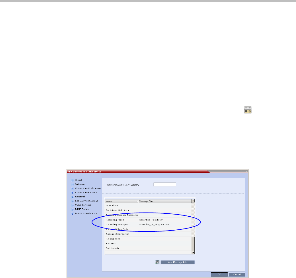
Polycom® RealPresence Collaboration ServerVirtual Edition Administrator’s Guide
13-4 Polycom, Inc.
4Click OK.
The Recording Link is added to the Collaboration Server unit.
Enabling the Recording Features in a Conference IVR Service
To record a conference, a Conference IVR Service in which the recording messages and DTMF
codes are activated must be assigned to the conference. The default Conference IVR Service
shipped with the Collaboration Server includes the recording-related voice messages and
default DTMF codes that enable the conference chairperson to control the recording process
from the endpoint. You can modify these default settings.
To modify the default recording settings for an existing Conference IVR Service:
1In the Collaboration Server Management pane, click the IVR Services ( ) button.
The IVR Services are listed in the IVR Services list pane.
2To modify the default recording settings, double-click the Conference IVR Service or
right-click and select Properties.
The Conference IVR Service Properties dialog box is displayed.
3To assign voice messages other than the default, click the General tab and scroll down
the list of messages to the recording messages.
4Select the Recording In Progress message, and then select the appropriate message file
(by default, Recording_in_Progress.wav) from the file list to the right of the field.
5Select the Recording Failed message, and then select the appropriate message file (by
default, Recording_Failed.wav) from the file list to the right of the field.
6To modify the default DTMF codes, click the DTMF Codes tab.
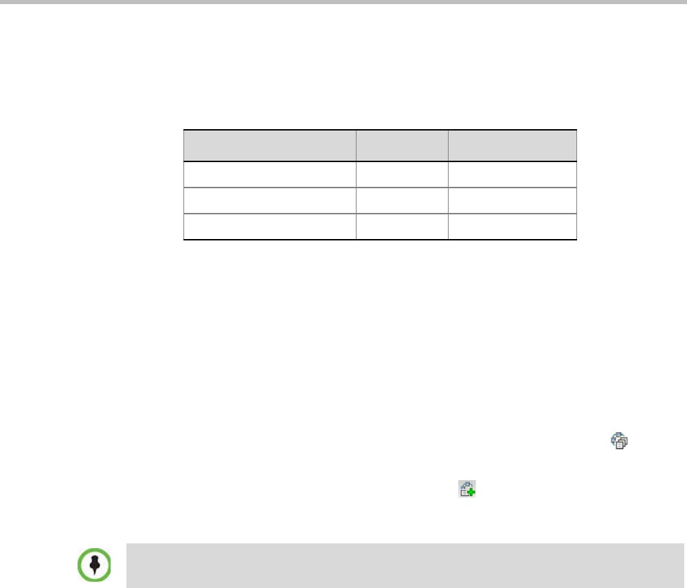
Chapter 13-Recording Conferences
Polycom, Inc. 13-5
7To modify the DTMF code or permission for a recording function:
aSelect the desired DTMF name (Start, Stop or Pause Recording), click the DTMF
code entry and type a new code.
bIn the Permission entry, select whether this function can be used by all conference
participants or only the chairperson.
8Click OK.
Enabling the Recording in the Conference Profile
To be able to record a conference, the recording options must be enabled in the Conference
Profile assigned to it. You can add recording to existing Profiles by modifying them.
To enable recording for a conference:
1In the Collaboration Server Management pane, click the Conference Profiles ( ) button.
The Conference Profiles list is displayed.
2Create a new profile by clicking the New Profile ( ) button or modify an existing
profile by double-clicking or right-clicking an existing profile and then selecting Profile
Properties.
3In the Profile Properties dialog box, click the Recording tab.
Table 13-2 Default DTMF Codes assigned to the recording process
Recording Operation DTMF Code Permission
Start or Resume Recording *3 Chairperson
Stop Recording *2 Chairperson
Pause Recording *1 Chairperson
If creating a new profile, complete the conference definition. For more information on creating
Profiles see on "Defining New Profiles” on page 2-20.
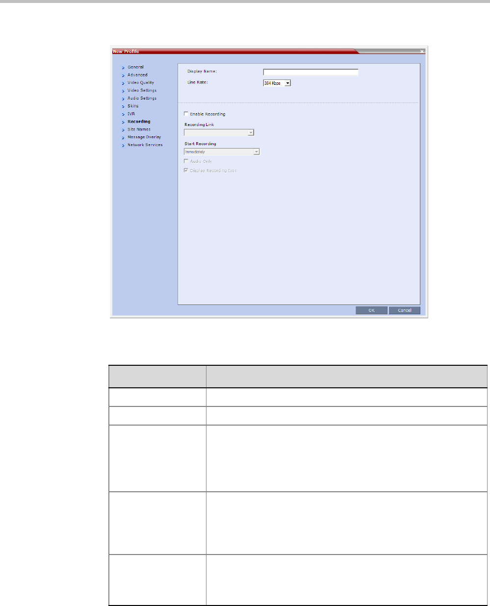
Polycom® RealPresence Collaboration ServerVirtual Edition Administrator’s Guide
13-6 Polycom, Inc.
4Select the Enable Recording check box.
5Define the following parameters:
6Click OK.
Recording is enabled in the Conference Profile.
Table 13-3 Conference Profile Recording Parameters
Parameter Description
Enable Recording Select to enable Recording Settings in the dialog box.
Recording Link Select a recording link for the conference from the list.
Start recording Select one of the following:
•Immediately – conference recording is automatically started
upon connection of the first participant.
•Upon Request – the operator or chairperson must initiate the
recording (manual).
Audio only Select this option to record only the audio channel of the conference.
Note:
An Audio Only Recording Link cannot be used to record a conference
if there are no Voice resources allocated in the Video/Voice Port
Configuration.
Display Recording
Icon
Select this option to display Recording Indication to all conference
participants informing them that the conference is being recorded.
The recording icon is replaced by a Paused icon when conference
recording is paused.

Chapter 13-Recording Conferences
Polycom, Inc. 13-7
Recording Link Encryption
The Recording Link can be encrypted when recording an encrypted conference. The
encryption of the Recording Link is enabled when Encryption is selected in the Conference
Profile on the Collaboration Server and on the RSS, and the system flag
ALLOW_NON_ENCRYPT_RECORDING_LINK_IN_ENCRYPT_CONF is set to NO.
Recording Link Encryption Guidelines:
•The Recording Link connection type must be H.323.
•The Recording Link uses the AES encryption format.
•The RSS 4000 recorder must be set to support encryption. For more information see the
RSS 4000 User Manual.
• Encryption must be selected in the Conference Profile.
Recording Link Encryption Flag Setting
Recording Links are treated as regular participants, however if the
ALLOW_NON_ENCRYPT_RECORDING_LINK_IN_ENCRYPT_CONF System Flag is set to
YES a non-encrypted Recording Link is to be allowed to connect to an encrypted conference.
Table 13-4 summarizes the connection possibilities for a Recording Link that is to be
connected to a conference for each of the conference profile and Entry Queue encryption
options.
Recording Link Settings
The recording of encrypted conferences via an encrypted Recording Link is enabled in the
Conference Profile by:
• Selecting the Encryption option (Encrypt All or Encrypt when Possible) in the Advanced
tab.
For more details, see "Media Encryption” on page 3-26.
• Setting the Recording options in the Recording tab. For more details, see "Enabling the
Recording in the Conference Profile” on page 13-5.
Table 13-4 Connections by Recording Link and Conference Encryption Settings
Conference
Profile Setting
Recording Link Connection Status according to flag:
ALLOW_NON_ENCRYPT_RECORDING_
LINK_IN_ENCRYPT_CONF
YES NO
Encrypt All
Connected encrypted if possible,
otherwise connected non-
encrypted.
Connected only if encrypted,
otherwise disconnected.
No Encryption Connected non-encrypted. Connected non-encrypted.
Encrypt when possible
Connected encrypted if possible,
otherwise connected non-
encrypted.
Connected encrypted if possible,
otherwise connected non-
encrypted.

Polycom® RealPresence Collaboration ServerVirtual Edition Administrator’s Guide
13-8 Polycom, Inc.
Managing the Recording Process
When a conference is started and recording is enabled in its Profile, the system will
automatically start the recording if the Start Recording parameter is set to immediately. If it is
set to Upon Request, the system waits for the chairperson or Collaboration Server user’s
request. Once the recording is initiated for a conference, the MCU connects to the recording
device (RSS 2000/4000) using the default Recording Link. The connection that is created
between the conference and the recording device is represented as a special participant
(Recording) whose name is the Recording Link. Once the recording has started, the recording
process can be stopped and restarted from the Chairperson’s endpoint (using DTMF codes)
or from the Collaboration Server Web Client. After the recording process has finished, the
recording can be identified in the RSS 2000/4000 by its Collaboration Server conference name.
Recording Link Layout
When the video layout of the conference is set to Auto Layout, the recording of the
conference will now include all the conference participants and not n-1 participants as in
previous versions.
In the new Auto Layout algorithm, the Recording Link is counted as a “participant” and
therefore it is excluded from the layout display used for the recording. The layout used for
the other participants will behave as in the “standard” Auto Layout behavior.
The Recording Link Layout can be changed during an ongoing conference in the same manner
as for any other conference participant. For more information see the "Participant Level
Monitoring” on page 12-19.
A conference participant and the Recording Link cannot have identical names, otherwise the
recording process will fail.
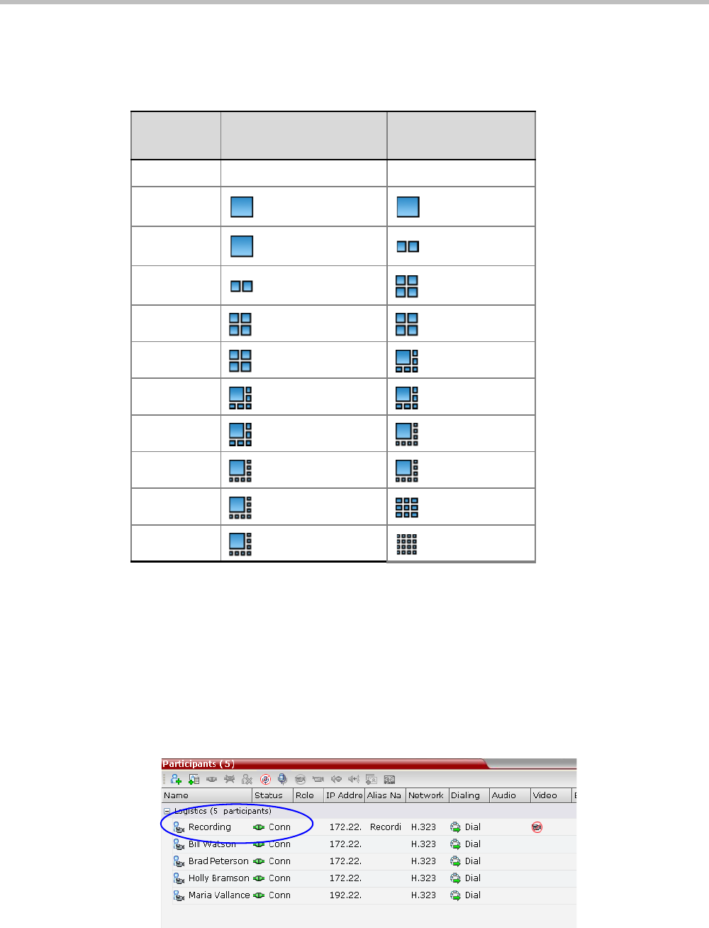
Chapter 13-Recording Conferences
Polycom, Inc. 13-9
The default settings for Auto Layout for the conference and the Recording Link are
summarized in the following table:
The default settings for Auto Layout of the Recording Link cannot be changed, and the Auto
Layout flags do not apply to the Recording Link Auto Layout default settings.
Using the Collaboration Server Web Client to Manage the Recording
Process
To manage the recording process using the right-click menu:
>> Right-click the Recording participant in the conference and select from one of the
following options:
Table 14 Recording Link Default Layout Settings (Auto Layout Mode)
Participants Conference Auto Layout
Default Settings
Recording Link Auto
Layout Settings
0Not applicable Not applicable
1
2
3
4
5
6
7
8
9
10 or more
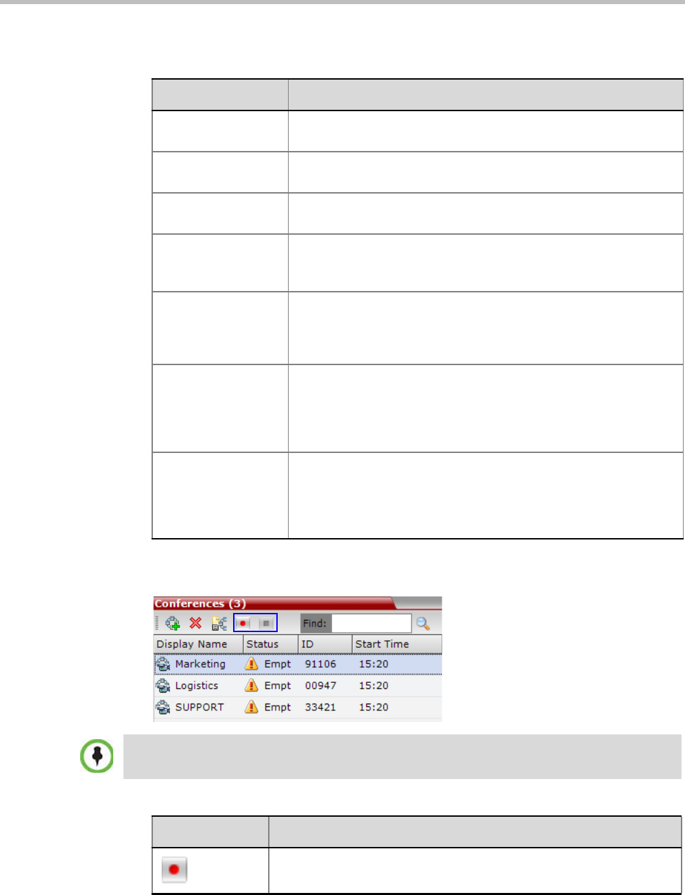
Polycom® RealPresence Collaboration ServerVirtual Edition Administrator’s Guide
13-10 Polycom, Inc.
To manage the recording process using the Conference toolbar:
>> In the Conferences pane, click one of the following buttons in the Conference tool bar.
Table 13-1 Recording Participant Right-click Options
Name Description
Start Starts recording. When recording has started, this option toggles with
the Pause option.
Pause Pauses the recording of the conference without disconnecting. When
the Recording is Paused, this option toggles with the Start option.
Resume Resumes the recording of the conference. The Resume option
toggles with the Pause option when it is used.
Stop Stops the recording.
Note: The Stop button is only enabled when the Recording is Started
or Paused.
Suspend Video The Suspend Video option prevents the incoming video of the
recording link participant to be part of the conference layout.
The Recording Link participant is set by default to Suspend Video.
The Suspend Video option toggles with the Resume Video option.
Resume Video The Resume Video option enables the incoming video of the
recording link participant to be part of the conference layout.
This feature may be used to play back previously recorded video or
audio feeds in the conference layout. For more information, see the
RSS 4000 User Guide.
Participant Properties The Participant Properties option displays viewing only information for
monitoring, e.g. communication capabilities and channels used to
connect to the conference. Users will not be able to perform any
functional requests from this window, i.e. disconnect, change layout
and mute.
The recording buttons will only be displayed in the conference tool bar for a conference that is
recording-enabled.
Table 13-2 Conferences List - Recording Tool bar buttons
Button Description
Start/Resume recording. This button toggles with the Pause button.
Chapter 13-Recording Conferences
Polycom, Inc. 13-11
Using DTMF Codes to Manage the Recording Process
By entering the appropriate DTMF code on the endpoint, the chairperson can Stop the
recording (*74), Pause it (*75), or Start/Resume the recording (*73). For more information on
managing the recording process via DTMF codes, see the RSS 2000 User’s Guide.
Recording between the Collaboration Server and the Codian VCR is enabled by adding an IP
participant to the recorded conference that acts as a link between the conference and the
recording device. This participant is identified as a recording link to the Codian VCR
according to the product ID sent from the VCR during the connection phase, in the call setup
parameters.
The video channel between the conference and the recording device is unidirectional where
the video stream is sent from the conference to the recorder.
If the Codian VCR opens a video channel to the conference - this channel is excluded from
the conference video mix.
To record a conference running on the Collaboration Server using Codian recorder:
>> In the conference, define or add a dial-out participant using the Codian VCR IP address
as the address for dialing.
Once added to the conference, the MCU automatically connects the participant (the link
to Codian VCR) and the recording is automatically started on the Codian VCR.
A connection can also be defined on the Codian VCR, dialing into the recorded conference
using the MCU prefix and the Conference ID as for any other dial-in participant in the
conference.
Monitoring the recording participant:
This connection is monitored as any other participant in the conference. The connection can
also be monitored in the Codian VCR web client.
Stop recording.
Pause recording. This button toggles with the Start/Resume button.
Table 13-2 Conferences List - Recording Tool bar buttons (Continued)
Button Description

Polycom® RealPresence Collaboration ServerVirtual Edition Administrator’s Guide
13-12 Polycom, Inc.

Polycom, Inc. 14-1
14
Users, Connections, and Notes
Users
Collaboration Server Web Client users are defined in the User’s table and can connect to the
MCU to perform various operations.
A maximum of 100 users can be defined per MCU.
User Types
The MCU supports the following user Authorization Levels:
—Administrator
—Operator
—Machine Account (Application-user)
—Administrator Read-only
—Chairperson
—Auditor
The authorization level determines a user’s capabilities within the system.
Administrator
An administrator can define and delete other users, and perform all configuration and
maintenance tasks.
Administrator Read-only
A user with Administrator permission with the same viewing and monitoring permissions
of a regular Administrator. However, this user is limited to creating system backups and
cannot perform any other configuration or conference related operation.
Operator
An Operator can manage Meeting Rooms, Profiles, Entry Queues, and SIP Factories, and
can also view the Collaboration Server configurations, but cannot change them.
Administrator and Operator users can verify which users are defined in the system. Neither
of them can view the user passwords, but an Administrator can change a password.
Chairperson
A Chairperson can only manage ongoing conferences and participants. The Chairperson
does not have access to the Collaboration Server configurations and utilities.
Users with Auditor authorization level cannot connect to the Collaboration Server via the RMX
Manager application and must use the Collaboration Server Web Client.
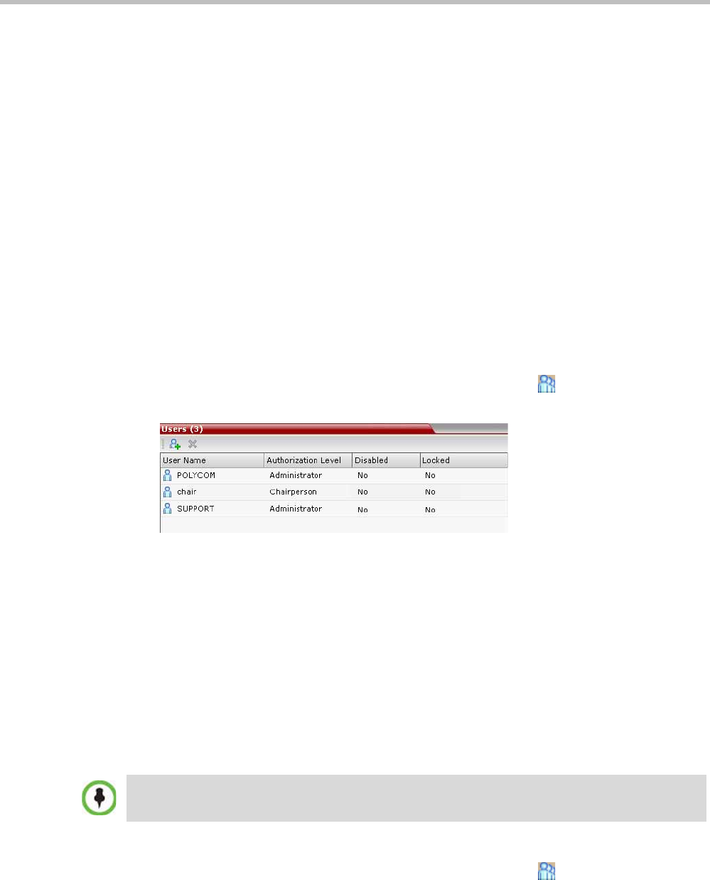
Polycom® RealPresence Collaboration ServerVirtual Edition Administrator’s Guide
14-2 Polycom, Inc.
Auditor
An Auditor can only view Auditor Files and audit the system.
Machine Account
User names can be associated with servers (machines) to ensure that all users are subject to
the same account and password policies. For more details, see "Machine Account” on
page 14-6.
Listing Users
The Users pane lists the currently defined users in the system and their authorization levels.
The pane also enables the administrators to add and delete users.
The system is shipped with a default Administrator user called POLYCOM, whose
password is POLYCOM. However, once you have defined other authorized Administrator
users, it is recommended to remove the default user.
You can view the list of users that are currently defined in the system.
To view the users currently defined in the system:
1In the Collaboration Server Management pane, click the Users ( ) button.
The Users pane is displayed.
The list includes three columns: User Name, Authorization Level and Disabled.
The User Name is the login name used by the user to connect to the MCU.
The Authorization indicates the Authorization Level assigned to the User: Administrator,
Administrator Read-only, Operator, Chairperson or Auditor.
Disabled indicates whether the user is disabled and cannot access the system unless
enabled by the administrator. For more details, see "Disabling a User” on page 14-4.
Locked indicates whether the user has been locked out and cannot access the system
unless enabled by the administrator.
Adding a New User
Administrators can add new users to the system.
To add a new user to the system:
1In the Collaboration Server Management pane, click the Users ( ) button.
2The Users pane is displayed.
The User Name and Password must be in ASCII.
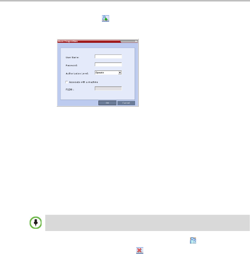
Chapter 14-Users, Connections, and Notes
Polycom, Inc. 14-3
3Click the New User ( ) button or right-click anywhere in the pane and then click New
User.
The User Properties dialog box opens.
4In the User Name text box, enter the name of the new user. This is the login name used
by the user when logging into the system.
5In the Password text box, enter the new user’s password. This will be the user’s
password when logging into the system.
6In the Authorization Level list, select the user type: Administrator, Administrator Read-
Only, Operator, Chairperson or Auditor.
7Optional. To associate a user with a machine:
aIn the User Properties dialog box, select the Associate with a machine check box.
bEnter the FQDN of the server that hosts the application who’s application-user
name is being added. Example: cma1.polycom.com
8Click OK.
The User Properties dialog box closes and the new user is added to the system.
Deleting a User
1In the Collaboration Server Management pane, click the Users ( ) button.
2Select the user and click the Delete ( ) button or right-click the user and then click
Delete User.
The system displays a confirmation message.
3In the confirmation dialog box, select Yes to confirm or No to cancel the operation.
If you select Yes, the user name and icon are removed from the system.
Changing a User’s Password
Users with Administrator authorization can change their own password and other users’
passwords. Users with Operator authorization can change their own password.
To delete a user, you must have Administrator authorization. The last remaining Administrator in the
Users list cannot be deleted.
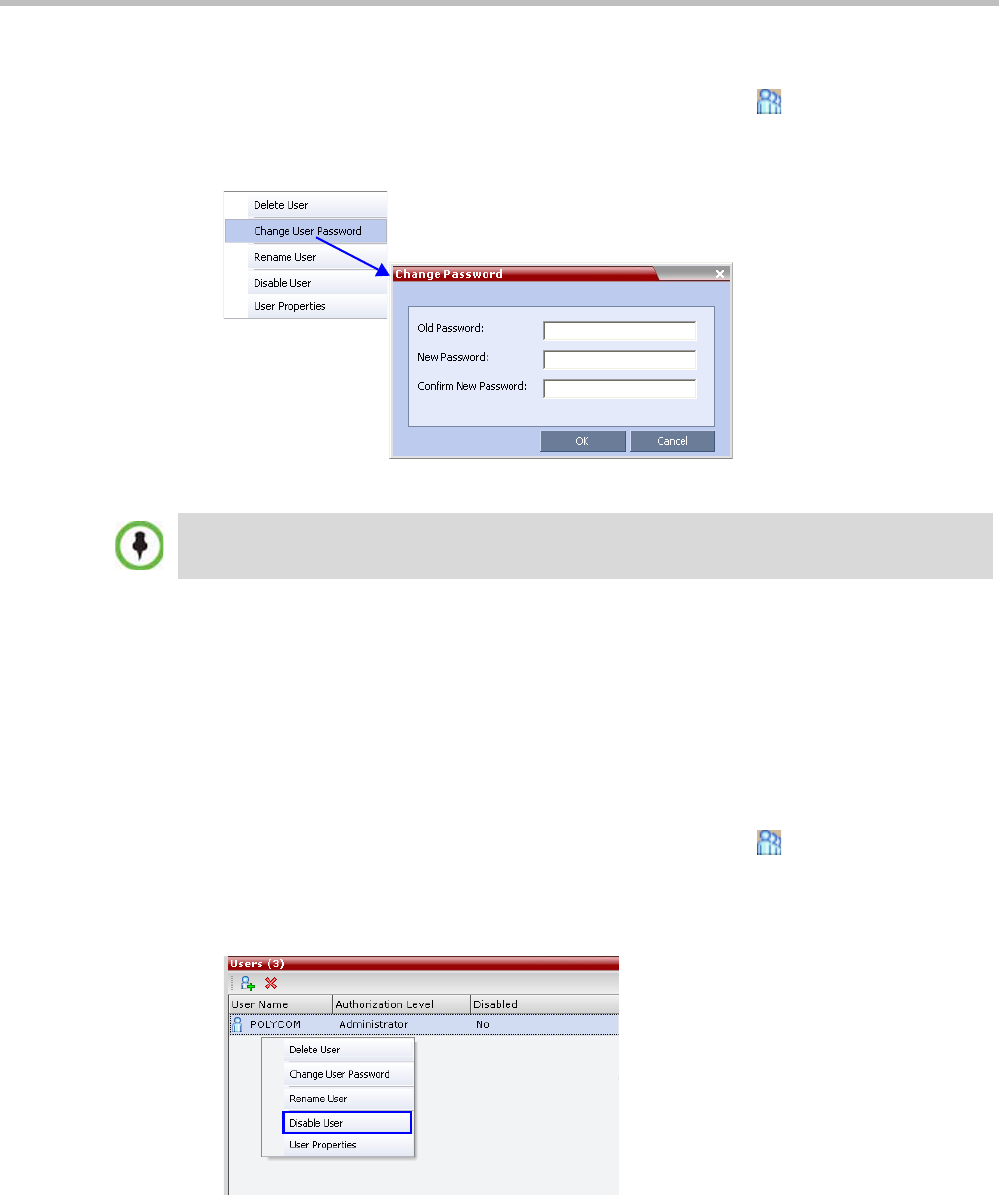
Polycom® RealPresence Collaboration ServerVirtual Edition Administrator’s Guide
14-4 Polycom, Inc.
To change a user’s password:
1In the Collaboration Server Management pane, click the Users ( ) option.
2Right-click the user and click Change User Password.
The Change Password dialog box opens.
3Enter the Old Password (current), New Password and Confirm the New Password.
4Click OK.
The user’s password is changed.
Disabling a User
An administrator can disable an enabled user. An indication is displayed in the Users List
when the User is disabled. An administrator can enable a disabled User.
To disable a user:
1In the Collaboration Server Management pane, click the Users ( ) button.
The Users pane is displayed.
2In the Users pane, right-click the user to be disabled and select Disable User in the
menu.
The Password must be in ASCII.
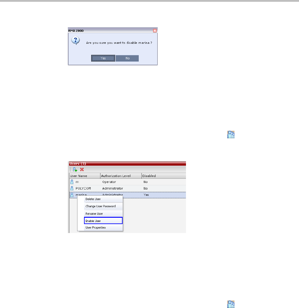
Chapter 14-Users, Connections, and Notes
Polycom, Inc. 14-5
A confirmation box is displayed.
3Click YES.
The User status in the Users list - Disabled column changes to Yes.
Enabling a User
An administrator can enable a User who was disabled manually by the administrator.
To enable a user:
1In the Collaboration Server Management pane, click the Users ( ) button.
The Users pane is displayed.
2Right-click the user to be enabled and select Enable User.
A confirmation box is displayed.
3Click YES.
The User status in the Users list - Disabled column changes to NO.
Renaming a User
To rename a user:
1In the Collaboration Server Management pane, click the Users ( ) button.
The Users pane is displayed.
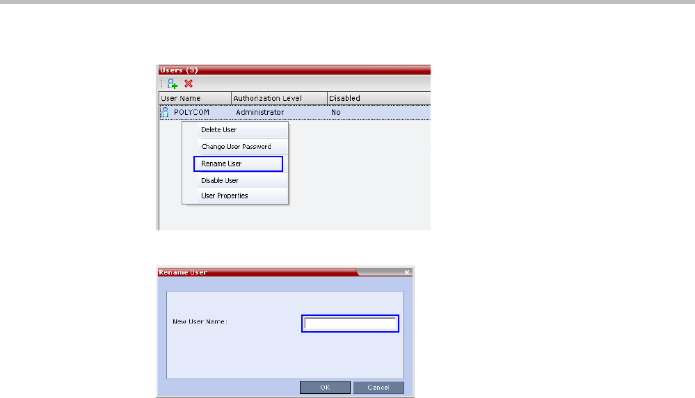
Polycom® RealPresence Collaboration ServerVirtual Edition Administrator’s Guide
14-6 Polycom, Inc.
2Right-click the user to be renamed and select Rename User.
The Rename User dialog box is displayed.
3Enter the user’s new name in the New User Name field and click OK.
The user is renamed and is forced to change his/her password.
Machine Account
User names can be associated with servers (machines) to ensure that all users are subject to
the same account and password policies.
For enhanced security reasons it is necessary for the Collaboration Server to process user
connection requests in the same manner, whether they be from regular users accessing the
Collaboration Server via the Collaboration Server Web Browser / RMX Manager or from
application-users representing applications such as CMA and RealPresence DMA system.
Regular users can connect from any workstation having a valid certificate while application-
users representing applications can only connect from specific servers. This policy ensures
that a regular user cannot impersonate an application-user to gain access to the Collaboration
Server in order to initiate an attack that would result in a Denial of Service (DoS) to the
impersonated application.
The connection process for an application-user connecting to the Collaboration Server is as
follows:
1The application-user sends a connection request, including its TLS certificate, to the
Collaboration Server.
2The Collaboration Server searches its records to find the FQDN that is associated with the
application-user’s name.
3If the FQDN in the received certificate matches that associated with application-user, and
the password is correct, the connection proceeds.

Chapter 14-Users, Connections, and Notes
Polycom, Inc. 14-7
Guidelines
•Application-users are only supported when TLS security is enabled and Request peer
certificate is selected. TLS security cannot be disabled until all application-user accounts
have been deleted from the system.
•For Secure Communications, an administrator must set up on the Collaboration Server
system a machine account for the RealPresence CMA/DMA/XMA system with which it
interacts. This machine account must include a fully-qualified domain name (FQDN)
for the RealPresence CMA/DMA/XMA system.
•Application-user names are the same as regular user names.
Example: the CMA application could have an application-user name of CMA1.
•The FQDN can be used to associate all user types: Administrator, Operator with the
FQDN of a server.
•Multiple application-users can be configured the same FQDN name if multiple
applications are hosted on the same server
• If the system is downgraded the application-user’s FQDN information is not deleted
from the Collaboration Server’s user records.
•A System Flag, PASS_EXP_DAYS_MACHINE, enables the administrator to change the
password expiration period of application-user’s independently of regular users. The
default flag value is 365 days.
• The server hosting an application-user whose password is about to expire will receive a
login response stating the number of days until the application-user’s password expires.
This is determined by the value of the
PASSWORD_EXPIRATION_WARNING_DAYS System Flag. The earliest warning
can be displayed 14 days before the password is due to expire and the latest warning
can be displayed 7 days before passwords are due to expire. An Active Alarm is created
stating the number of days before the password is due to expire.
•The MIN_PWD_CHANGE_FREQUENCY_IN_DAYS System Flag does not effect
application-user accounts. Applications typically manage their own password change
frequency.
• If an application-user identifies itself with an incorrect FQDN, its account will not be
locked, however the event is written to the Auditor Event File.
• If an application-user identifies itself with a correct FQDN and an incorrect password, its
account will be locked and the event written to the Auditor Event File.
•An application-user cannot be the last administrator in the system. The last administrator
must be regular user.
• User names are not case sensitive.
Monitoring
•An application-user and its connection is represented by a specific icon.
Active Directory
• When working with Active Directory, CMA, RealPresence DMA system, and XMA cannot
be registered within Active Directory as regular users. CMA and RealPresence DMA
system application-users must be manually.
• The only restriction is that TLS mode is enabled together with client certificate
validation.
• If the above configuration are set off it will not be possible to add machine accounts.
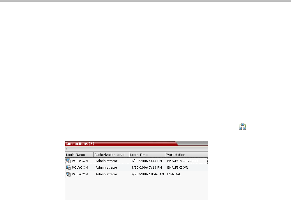
Polycom® RealPresence Collaboration ServerVirtual Edition Administrator’s Guide
14-8 Polycom, Inc.
• When setting the TLS mode off the system should check the existence of a machine
account and block this operation until all machine accounts are removed.
Connections
The Collaboration Server enables you to list all connections that are currently logged into the
MCU, e.g. users, servers or API users. The MCU issues an ID number for each login. The ID
numbers are reset whenever the MCU is reset.
A maximum of 50 users can be concurrently logged in to the MCU.
Viewing the Connections List
To list the users who are currently connected to the MCU:
1In the Collaboration Server Management pane, click the Connections ( ) button.
A list of connected users is displayed in the Connections pane.
The information includes:
—The user’s login name.
—The user’s authorization level (Chairperson, Operator, Administrator or Auditor).
—The time the user logged in.
—The name/identification of the computer used for the user’s connection.
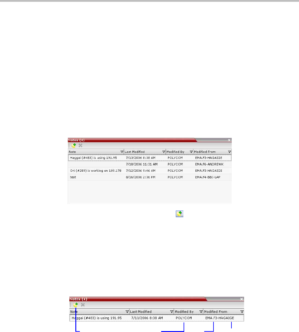
Chapter 14-Users, Connections, and Notes
Polycom, Inc. 14-9
Notes
Notes are the electronic equivalent of paper sticky notes. You can use notes to write down
questions, important phone numbers, names of contact persons, ideas, reminders, and
anything you would write on note paper. Notes can be left open on the screen while you
work.
Notes can be read by all system Users concurrently connected to the MCU. Notes that are
added to the Notes list are updated on all workstations by closing and re-opening the Notes
window. Notes can be written in any Unicode language.
Using Notes
To create a note:
1On the Collaboration Server menu, click Administration > Notes.
The Notes window opens.
2In the Notes toolbar, click the New Note ( ) button, or right-click anywhere inside the
Notes window and select New Note.
3In the Note dialog box, type the required text and click OK.
The new note is saved and closed. The Notes list is updated, listing the new note and its
properties:
—Note – The beginning of the note’s text.
—Last Modified – The date of creation or last modification.
—Modified By – The Login Name of the user who last modified the note.
—Modified From – The Client Application and Workstation from which the note was
created or modified.
To open or edit a note:
4Double-click the entry to edit, or right-click the entry and select Note Properties.
The note opens for viewing or editing.
User Name Client
Application
Workstation
Toolbar Handle

Polycom® RealPresence Collaboration ServerVirtual Edition Administrator’s Guide
14-10 Polycom, Inc.
To delete a note:
1In the Notes list, select the entry for the note to delete and click the Delete Note button
( ), or right-click the entry and select Delete Note.
A delete confirmation dialog box is displayed.
2Click OK to delete the note, or click Cancel to keep the note.
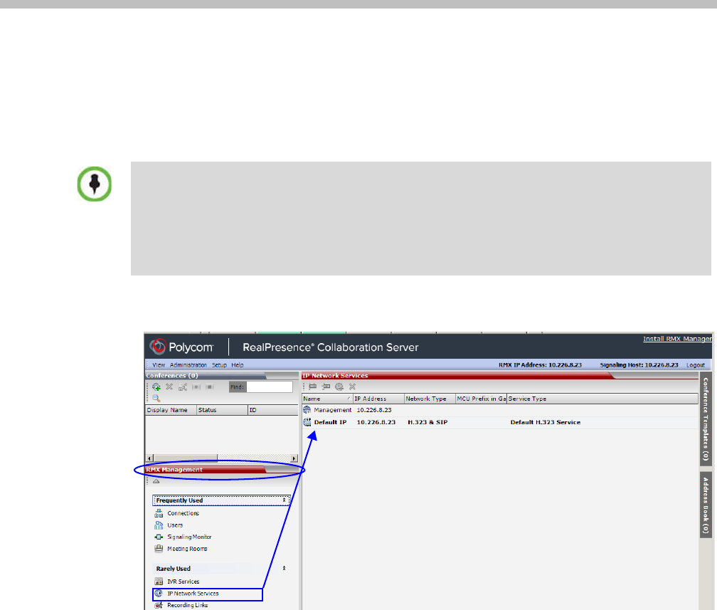
Polycom, Inc. 15-1
15
IP Network Services
To enable the RealPresence Collaboration Server Virtual Edition to function within IP
network environments, network parameters must be defined for the IP Network Services.
The configuration dialog boxes for the IP network services are accessed via the Collaboration
Server Management pane of the Collaboration Server Web Client.
IP Network Services
Two IP Services are defined for the Collaboration Server:
•Management Network
•Default IP Service (Conferencing Service)
Dial in, dial out connections and Collaboration Server management are supported within
IPv4 addressing environments. Both IP Services use the same IP. Therefore, only one IP is
needed for the Collaboration Server.
The RealPresence Collaboration Server Virtual Edition allows you only to view the parameters of the
IP Network Services in theRealPresence Collaboration Server Web Client or the but you cannot
define a new IP Network Service or modify the parameters of an existing Network Service.
Attempting to do so may cause unexpected results, including complete inability to use or access the
RealPresence Collaboration Server. These settings can be modified only using the text user
interface. For more information, see the Polycom® RealPresence Collaboration Server Virtual
Edition Getting Started Guide, "Manual IP Configuration” on page 2-22.

Polycom® RealPresence Collaboration ServerVirtual Edition Administrator’s Guide
15-2 Polycom, Inc.
Management Network (Primary)
The Management Network is used to control the Collaboration Server, mainly via the
RealPresence Collaboration Server Web Client application. The Management Network contains
the network parameters, such as the IP address of the Control Unit, needed for connection
between the Collaboration Server unit and the RP Collaboration Server Web Client. This IP
address can be used by the administrator or service personnel to connect to the Control Unit
should the MCU become corrupted or inaccessible.
In a typical environment where DHCP is enabled, the Management Network parameters are
automatically set during First Time Power-up and whenever the Collaboration Server is
restarted. In an environment where DHCP is not enabled, the Management Network
properties must be set manually. For more information, see the Polycom® RealPresence
Collaboration Server Virtual Edition Getting Started Guide, "Manual IP Configuration” on
page 2-22.
Default IP Service (Conferencing Service - Media and signaling)
The Default IP Service (media and signaling) is used to configure and manage communications
between the Collaboration Server and conferencing devices such as endpoints, gatekeepers,
SIP servers, etc. The same IP is used for both the Management Network and the Default IP
Service.
The Default IP Service contains parameters for:
• Signaling Host IP Address
• External conferencing devices
Calls from all external IP entities are made to the Signaling Host, which initiates call set-up.
Conferencing related definitions such as environment (H.323 or SIP) are also defined in this
service.
In a typical environment where DHCP is enabled, the Default IP Service is configured
automatically during First Time Power-up and whenever the Collaboration Server is
restarted, using the same parameters as are used for the Management Network. In an
environment where DHCP is not enabled, the Default IP Service properties are set when the
Management Network properties are set manually. For more information, see the Polycom®
RealPresence Collaboration Server Virtual Edition Getting Started Guide, "Manual IP
Configuration” on page 2-22.
Modifying the Management Network
To view the Management Network Service:
1In the Collaboration Server RMX Management pane, click the IP Network Services ()
button.
2In the IP Network Services list pane, double-click the Management Network () entry.
Changes made to any of these parameters only take effect when the Collaboration Server is reset.
An Active Alarm is created when changes made to the system have not yet been implemented and
the MCU must be reset.
In the RealPresence Collaboration Server Virtual Edition, these settings can only be changed in the
console Text User Interface. For more information, see the Polycom® RealPresence Collaboration
Server Virtual Edition Getting Started Guide, "Manual IP Configuration” on page 2-22.
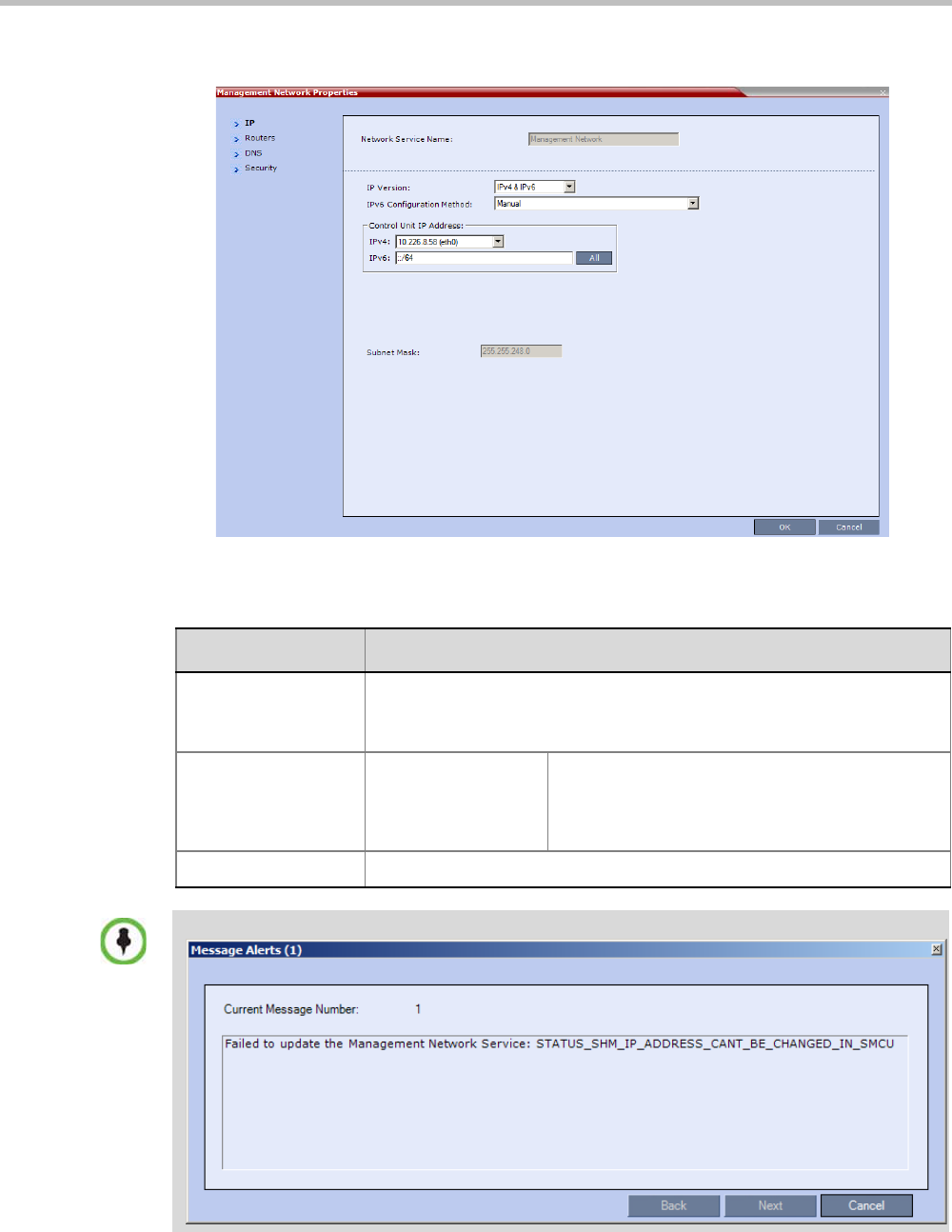
Chapter 15-IP Network Services
Polycom, Inc. 15-3
The Management Network Properties - IP dialog box opens.
The following fields can be viewed, but can not be modified:
Table 15-1 Default Management Network Service – IP
Field Description
Network Service
Name
Displays the name of the Management Network. This name cannot be
modified.
Note: This field is displayed in all Management Network Properties tabs.
Control Unit IP
Address
IPv4 The IPv4 address of the Collaboration Server.
This IP address is used by the Collaboration
Server Web Client to connect to the Collaboration
Server.
Subnet Mask The subnet mask of the Management Network Service.
If an attempt is made to modify these settings, the message below will be displayed:
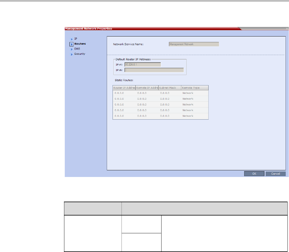
Polycom® RealPresence Collaboration ServerVirtual Edition Administrator’s Guide
15-4 Polycom, Inc.
3Click the Routers tab.
The following fields can be viewed but not modified.:
Table 15-2 Default Management Network Service – Routers
Field Description
Default Router
IP Address
IPv4 The IP address of the default router. The default
router is used whenever the defined static routers
are not able to route packets to their destination.
The default router is also used when host access is
restricted to one default router.
IPv6

Chapter 15-IP Network Services
Polycom, Inc. 15-5
Static Routes The system uses Static Routes to search other
networks for endpoint addresses that are not found
on the local LAN.
Up to five routers can be defined in addition to the
Default Router. The order in which the routers
appear in the list determines the order in which the
system looks for the endpoints on the various
networks. If the address is in the local subnet, no
router is used.
To define a static route (starting with the first), click
the appropriate column and enter the required
value.
Router IP
Address
The IP address of the router.
Remote IP
Address
The IP address of the entity to be reached outside
the local network. The Remote Type determines
whether this entity is a specific component (Host) or
a network.
•If Host is selected in the Remote Type field,
enter the IP address of the endpoint.
•If Network is selected in the Remote Type field,
enter of the segment of the other network.
Remote
Subnet Mask
The subnet mask of the remote network.
Remote Type The type of router connection:
•Network – defines a connection to a router
segment in another network.
•Host – defines a direct connection to an
endpoint found on another network.
Table 15-2 Default Management Network Service – Routers (Continued)
Field Description
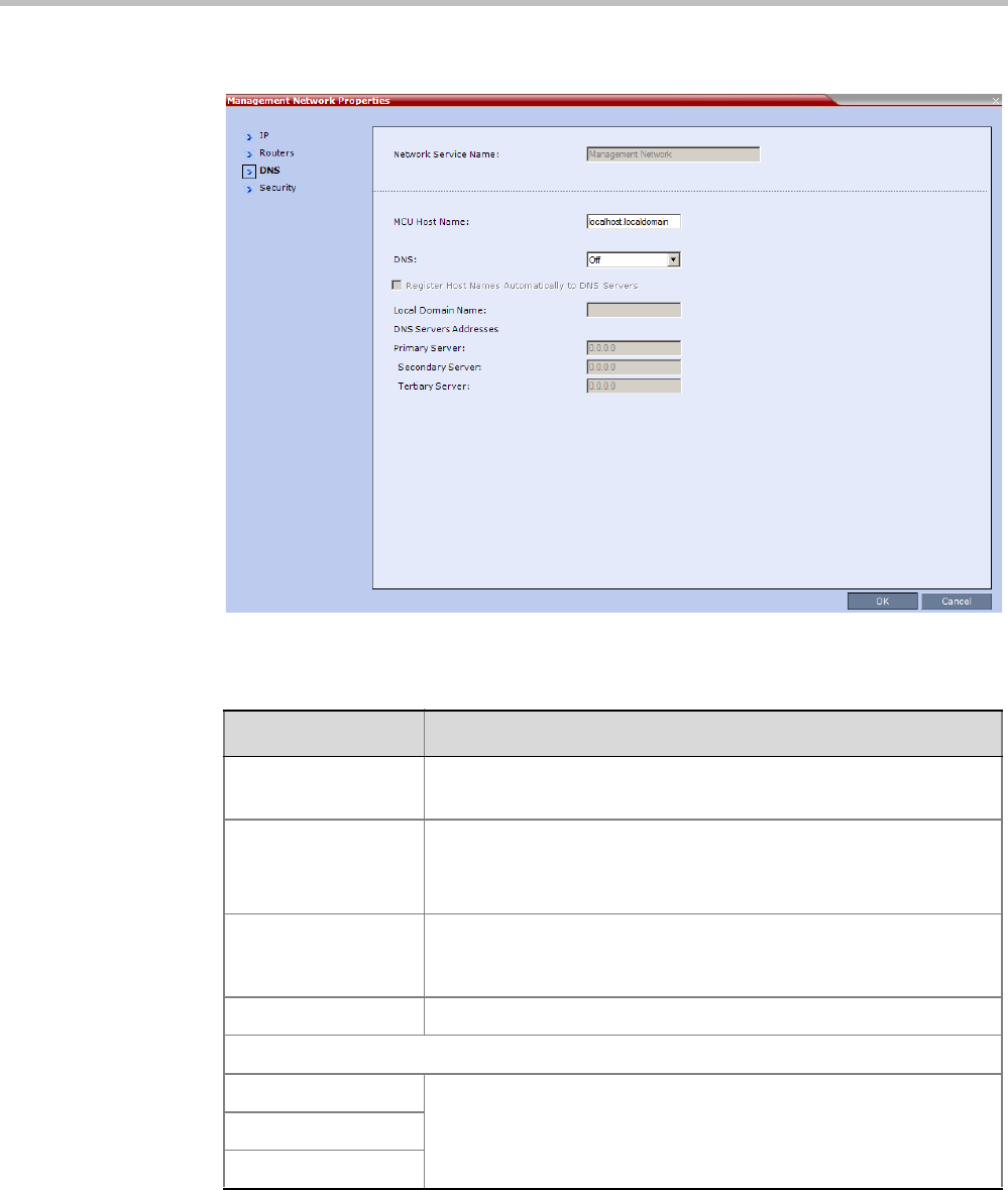
Polycom® RealPresence Collaboration ServerVirtual Edition Administrator’s Guide
15-6 Polycom, Inc.
4Click the DNS tab.
The following fields can be modified, but their values will not be applied:
Table 15-3 Default Management Network Service – DNS
Field Description
MCU Host Name The name of the MCU on the network.
Default name is PolycomMCU
DNS •Off – if DNS servers are not used in the network.
•Specify – to enter the IP addresses of the DNS servers.
Note: The IP address fields are enabled only if Specify is selected.
Register Host Names
Automatically to DNS
Servers
Select this option to automatically register the MCU Signaling Host
with the DNS server.
Local Domain Name Enter the name of the domain where the MCU is installed.
DNS Servers Addresses:
Primary Server
The static IP addresses of the DNS servers.
A maximum of three servers can be defined.
Secondary Server
Tertiary Server
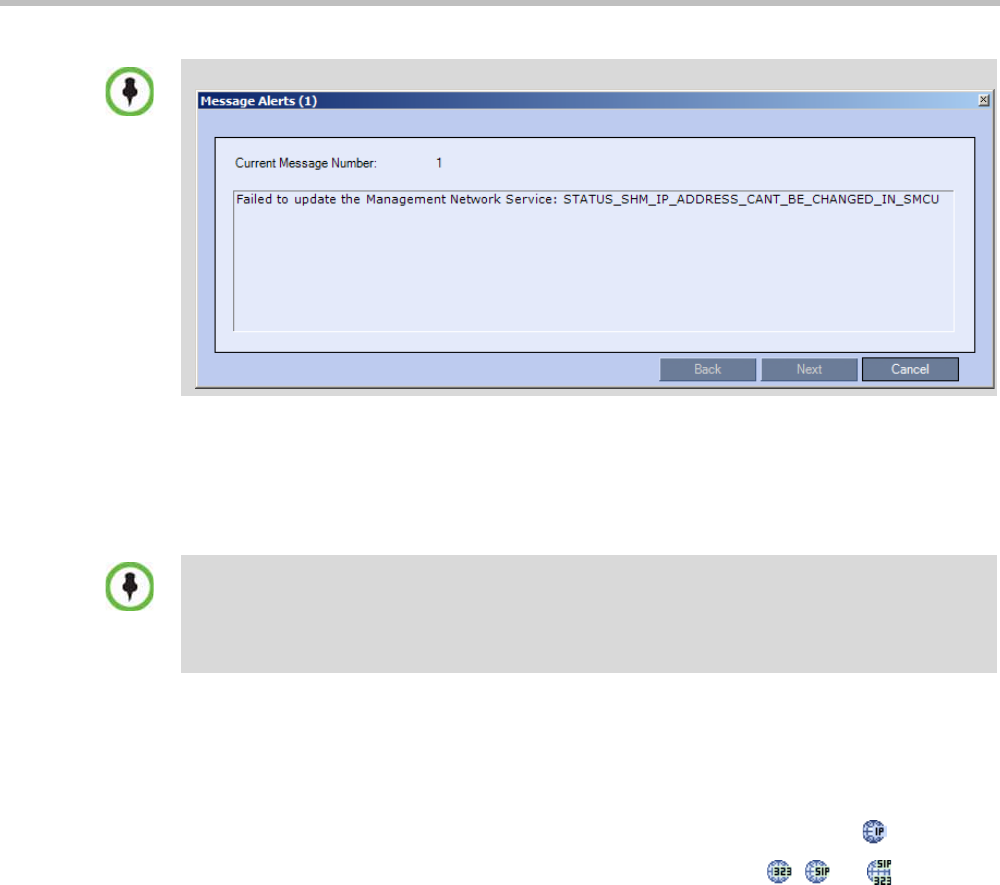
Chapter 15-IP Network Services
Polycom, Inc. 15-7
5Click OK.
6If you have modified the Management Network Properties, reset the MCU.
Modifying the Default IP Network Service
The Default IP Service parameters need to be modified if you want to change the:
• Gatekeeper parameters or add gatekeepers to the Alternate Gatekeepers list
• SIP server parameters
To view or modify the Default IP Service:
1In the Collaboration Server Management pane, click IP Network Services ().
2In the Network list pane, double-click the Default IP Service ( , , or ) entry.
If an attempt is made to modify these settings, the message below will be displayed:
In the RealPresence Collaboration Server Virtual Edition, both the Default IP Network Service and
the Management Network Service use the same IP address and subnet mask. These settings can
be modified only using the text user interface. To modify the IP address and subnet mask, see the
Polycom® RealPresence Collaboration Server Virtual Edition Getting Started Guide, "Manual IP
Configuration” on page 2-22.
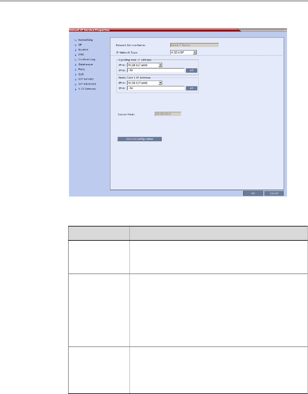
Polycom® RealPresence Collaboration ServerVirtual Edition Administrator’s Guide
15-8 Polycom, Inc.
The Default IP Service - Networking IP dialog box opens.
3 Modify the following fields:
Table 15-4 Default IP Network Service – IP
Field Description
Network Service
Name
The name Default IP Service is assigned to the IP Network Service by
the Fast Configuration Wizard. This field can not be changed.
Note: This field is displayed in all IP Signaling dialog boxes and can
contain character sets that use Unicode encoding.
IP Network Type Displays the network type selected during the First Entry
configuration. The Default IP Network icon indicates the selected
environment.
You can select:
•H.323: For an H.323-only Network Service.
•SIP: For a SIP-only Network Service.
•H.323 & SIP: For an integrated IP Service. Both H.323 and SIP
participants can connect to the MCU using this service.
Note: This field is displayed in all Default IP Service tabs.
Signaling Host IP
Address
This field can not be changed. One IP address is used for signaling
and media transmission.
Dial out calls from the Collaboration Server are initiated from this
address.
This address is used to register the RMX with a Gatekeeper or a SIP
Proxy server.
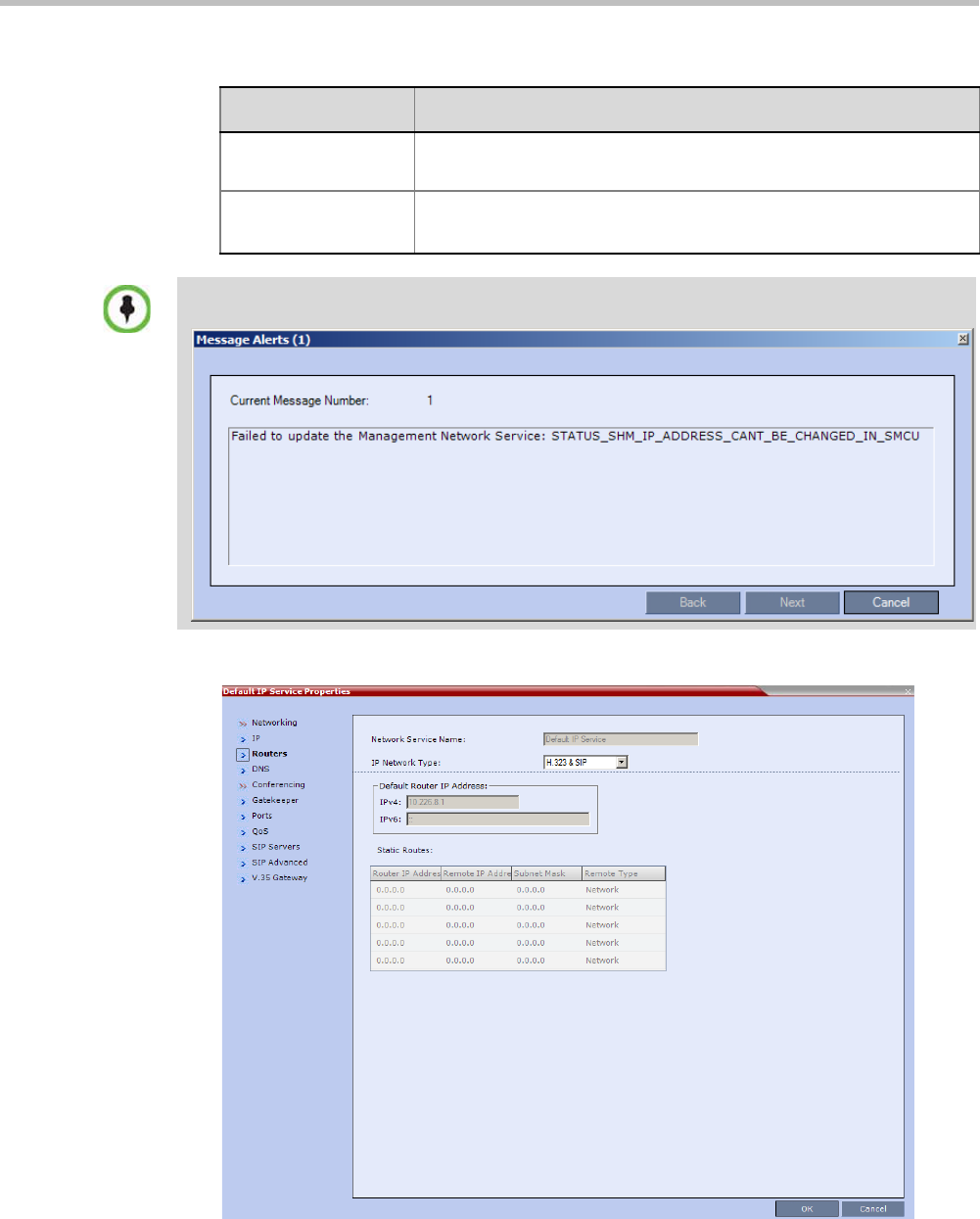
Chapter 15-IP Network Services
Polycom, Inc. 15-9
4Click the Routers tab.
With the exception of IP Network Type, the field definitions of the Routers tab are the
same as for the Default Management Network. For more information see page 15-4.
Media Card 1
IP Address
This field can not be changed. One IP address is used for signaling
and media transmission.
Subnet Mask The subnet mask of the MCU. This field can not be changed.
Default value: 255.255.255.0.
If an attempt is made to modify settings that can not be modified, the message below will be
displayed after clicking OK.:
Table 15-4 Default IP Network Service – IP (Continued)
Field Description
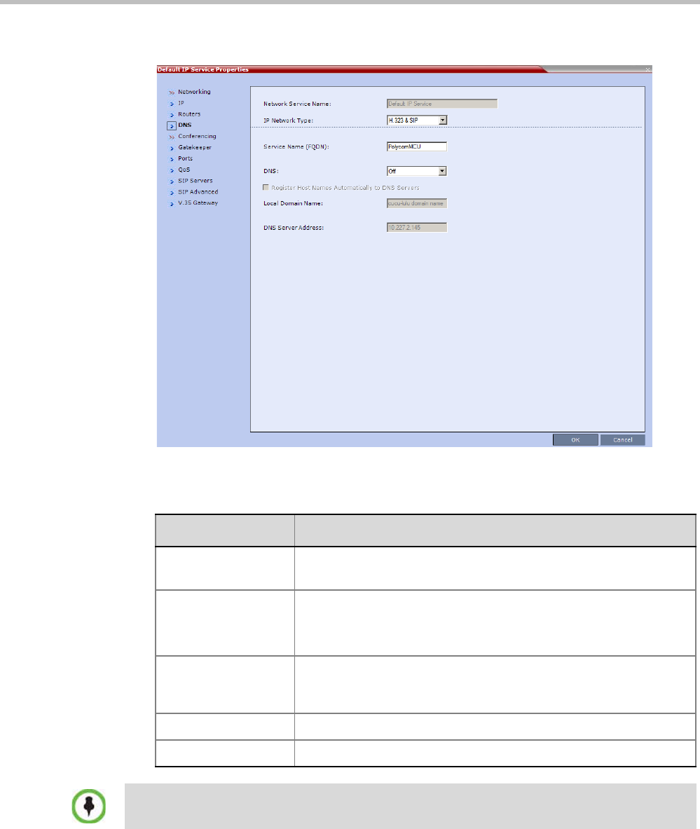
Polycom® RealPresence Collaboration ServerVirtual Edition Administrator’s Guide
15-10 Polycom, Inc.
5Optional. Click the DNS tab.
The following fields can be modified, but their values will not be applied:
Table 15-5 Default Management Network Service – DNS
Field Description
Service Name
(FQDN)
The name of the MCU on the network.
Default name is PolycomMCU
DNS •Off – if DNS servers are not used in the network.
•Specify – to enter the IP addresses of the DNS servers.
Note: The IP address fields are enabled only if Specify is selected.
Register Host Names
Automatically to DNS
Servers
Select this option to automatically register the MCU Signaling Host
with the DNS server.
Local Domain Name Enter the name of the domain where the MCU is installed.
DNS Server Address The static IP addresses of the DNS server.
If an attempt is made to modify these settings, the MCU will prompt you to reset. Regardless, these
settings will not be applied.
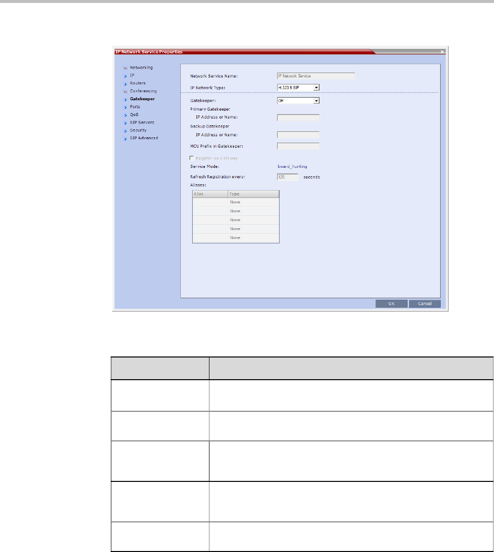
Chapter 15-IP Network Services
Polycom, Inc. 15-11
6Click the Gatekeeper tab.
7 Modify the following fields:
Table 15-6 Default IP Service – Conferencing – Gatekeeper Parameters
Field Description
Gatekeeper Select Specify to enable configuration of the gatekeeper IP address.
When Off is selected, all gatekeeper options are disabled.
Primary Gatekeeper
IP Address or Name
Enter either the gatekeeper’s host name as registered in the DNS or
IP address.
Backup Gatekeeper
IP Address or Name
Enter the DNS host name or IP address of the gatekeeper used as a
fallback gatekeeper used when the primary gatekeeper is not
functioning properly.
MCU Prefix in
Gatekeeper
Enter the number with which this Network Service registers in the
gatekeeper. This number is used by H.323 endpoints as the first part
of their dial-in string when dialing the MCU.
Register as Gateway Select this check box if the Collaboration Server is to be seen as a
gateway, for example, when using a Cisco gatekeeper.

Polycom® RealPresence Collaboration ServerVirtual Edition Administrator’s Guide
15-12 Polycom, Inc.
8Click the Ports tab.
Refresh Registration
every __ seconds
The frequency with which the system informs the gatekeeper that it is
active by re-sending the IP address and aliases of the system to the
gatekeeper. If the system does not register within the defined time
interval, the gatekeeper will not refer calls to the system until it re-
registers. If set to 0, re-registration is disabled.
Note:
•It is recommended to use default settings.
•This is a re-registration and not a ‘keep alive’ operation – an
alternate gatekeeper address may be returned.
Aliases:
Alias The alias that identifies the Collaboration Server’s Signaling Host
within the network. Up to five aliases can be defined for each
Collaboration Server.
Note: When a gatekeeper is specified, at least one alias must be
entered in the table.
Additional aliases or prefixes may also be entered.
Type The type defines the format in which the system alias is sent to the
gatekeeper. Each alias can be of a different type:
•H.323 ID (alphanumeric ID)
•E.164 (digits 0-9, * and #)
•Email ID (email address format,
e.g. abc@example.com)
•Participant Number (digits 0-9, * and #)
Note: Although all types are supported, the type of alias to be used
depends on the gatekeeper’s capabilities.
Table 15-6 Default IP Service – Conferencing – Gatekeeper Parameters (Continued)
Field Description
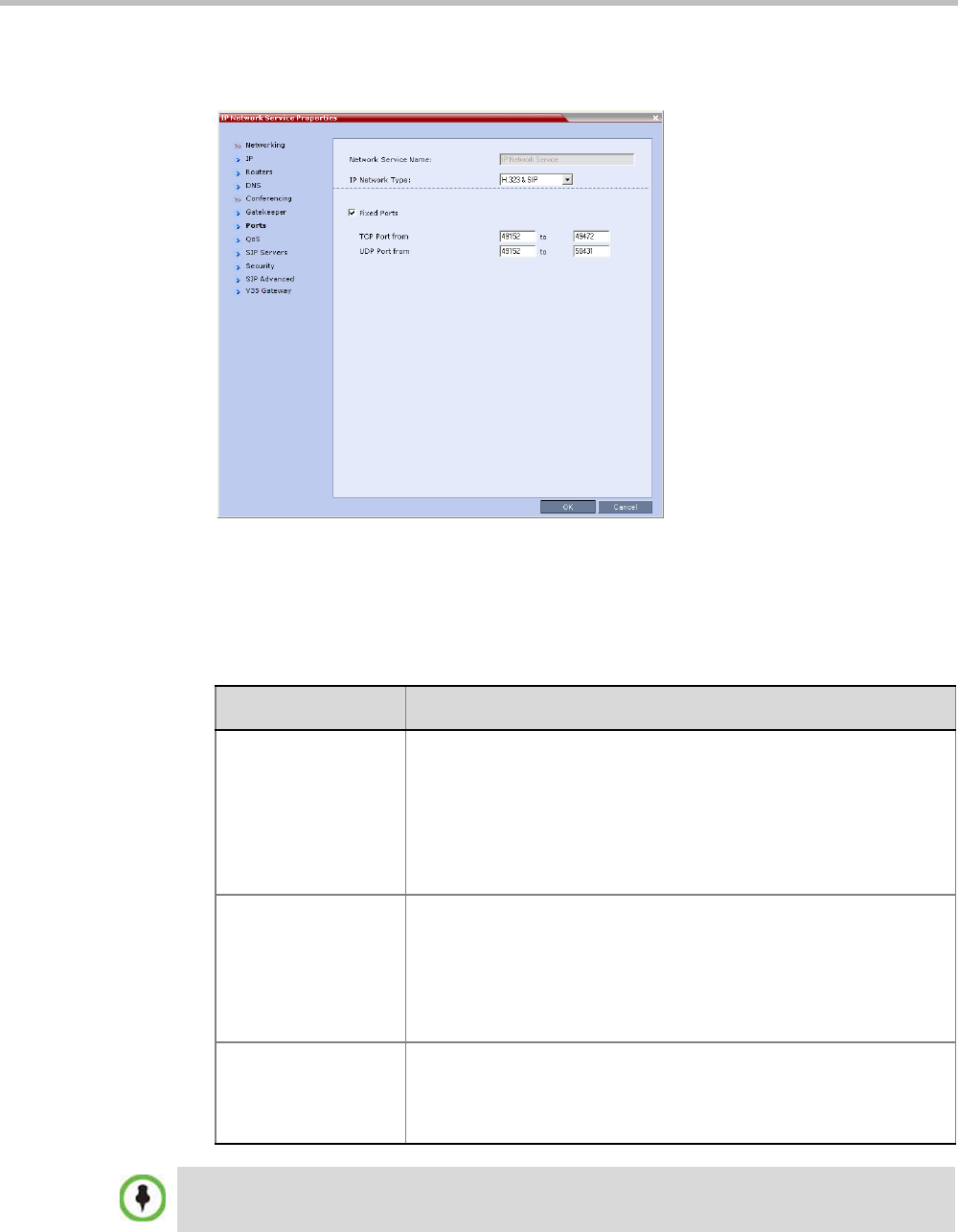
Chapter 15-IP Network Services
Polycom, Inc. 15-13
Settings in the Ports tab allow specific ports in the firewall to be allocated to multimedia
conference calls.
The port range recommended by IANA (Internet Assigned Numbers Authority) is
49152 to 65535. The Collaboration Server uses this recommendation along with the
number of licensed ports to calculate the port range.
9 Modify the following fields:
Table 15-7 Default IP Service – Conferencing – Ports Parameters
Field Description
Fixed Ports Leave this check box cleared if you are defining a Network Service for
local calls that do not require configuring the firewall to accept calls
from external entities. When cleared, the system uses the default port
range and allocates 4 RTP and 4 RTCP ports for media channels
(Audio, Video, Content and FECC).
Click this check box to manually define the port ranges or to limit the
number of ports to be left open.
TCP Port from - to Displays the default settings for port numbers used for signaling and
control.
To modify the number of TCP ports, enter the first and last port
numbers in the range.
The number of ports is calculated as follows:
Number of simultaneous calls x 2 ports (1 signaling + 1 control).
UDP Port from - to Displays the default settings for port numbers used for audio and
video.
To modify the number of UDP ports, enter the first and last port
numbers in the range, and the range must be 1024 ports.
If the network administrator does not specify an adequate port range, the system will accept the
settings and issue a warning. Calls will be rejected when the Collaboration Server’s ports are
exceeded.
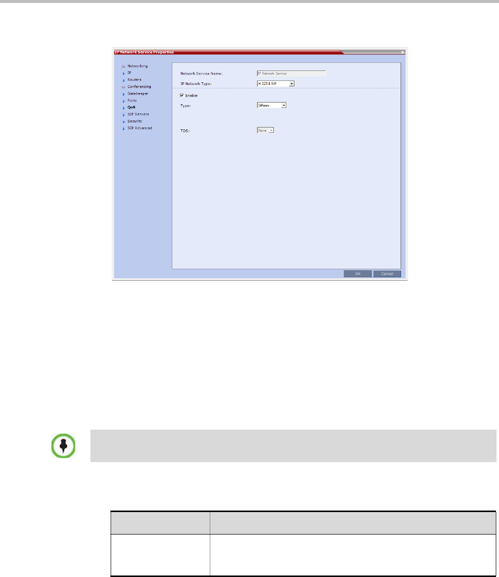
Polycom® RealPresence Collaboration ServerVirtual Edition Administrator’s Guide
15-14 Polycom, Inc.
10 If required, click the QoS tab.
Quality of Service (QoS) is important when transmitting high bandwidth audio and
video information. QoS can be measured and guaranteed in terms of:
• Average delay between packets
• Variation in delay (jitter)
• Transmission error rate
DiffServ and Precedence are the two QoS methods supported by the Collaboration
Server. These methods differ in the way the packet’s priority is encoded in the packet
header.
The Collaboration Server’s implementation of QoS is defined per Network Service, not
per endpoint.
11 View or modify the following fields:
The routers must support QoS in order for IP packets to get higher priority.
Table 15-8 Default IP Service – Conferencing – QoS Parameters
Field Description
Enable Select to enable the configuration and use of the QoS settings.
When un-checked, the values of the DSCP (Differentiated Services
Code Point) bits in the IP packet headers are zero.

Chapter 15-IP Network Services
Polycom, Inc. 15-15
Type DiffServ and Precedence are two methods for encoding packet
priority. The priority set here for audio video and IP Signaling packets
should match the priority set in the router.
•DiffServ: Select when the network router uses DiffServ for priority
encoding.
The default priorities for both audio and video packets is 0x88.
These values are determined by the QOS_IP_VIDEO and
QOS_IP_AUDIO flags.
The default priority for Signaling IP traffic is 0x00 and is
determined by the QOS_IP_SIGNALING flag.
For more information see "Modifying System Flags” on page 20-1.
•Precedence: Select when the network router uses Precedence
for priority encoding, or when you are not sure which method is
used by the router. Precedence should be combined with None in
the TOS field.
The default priority is 5 for audio and 4 for video packets.
Note: Precedence is the default mode as it is capable of providing
priority services to all types of routers, as well as being currently
the most common mechanism.
Audio / Video You can prioritize audio and video IP packets to ensure that all
participants in the conference hear and see each other clearly. Select
the desired priority. The scale is from 0 to 5, where 0 is the lowest
priority and 5 is the highest. The recommended priority is 4 for audio
and 4 for video to ensure that the delay for both packet types is the
same and that audio and video packets are synchronized and to
ensure lip sync.
TOS Select the type of Service (TOS) that defines optimization tagging for
routing the conferences audio and video packets.
•Delay: The recommended default for video conferencing;
prioritized audio and video packets tagged with this definition are
delivered with minimal delay (the throughput of IP packets
minimizes the queue sequence and the delay between packets).
•None: No optimization definition is applied. This is a compatibility
mode in which routing is based on Precedence priority settings
only. Select None if you do not know which standard your router
supports.
Table 15-8 Default IP Service – Conferencing – QoS Parameters (Continued)
Field Description
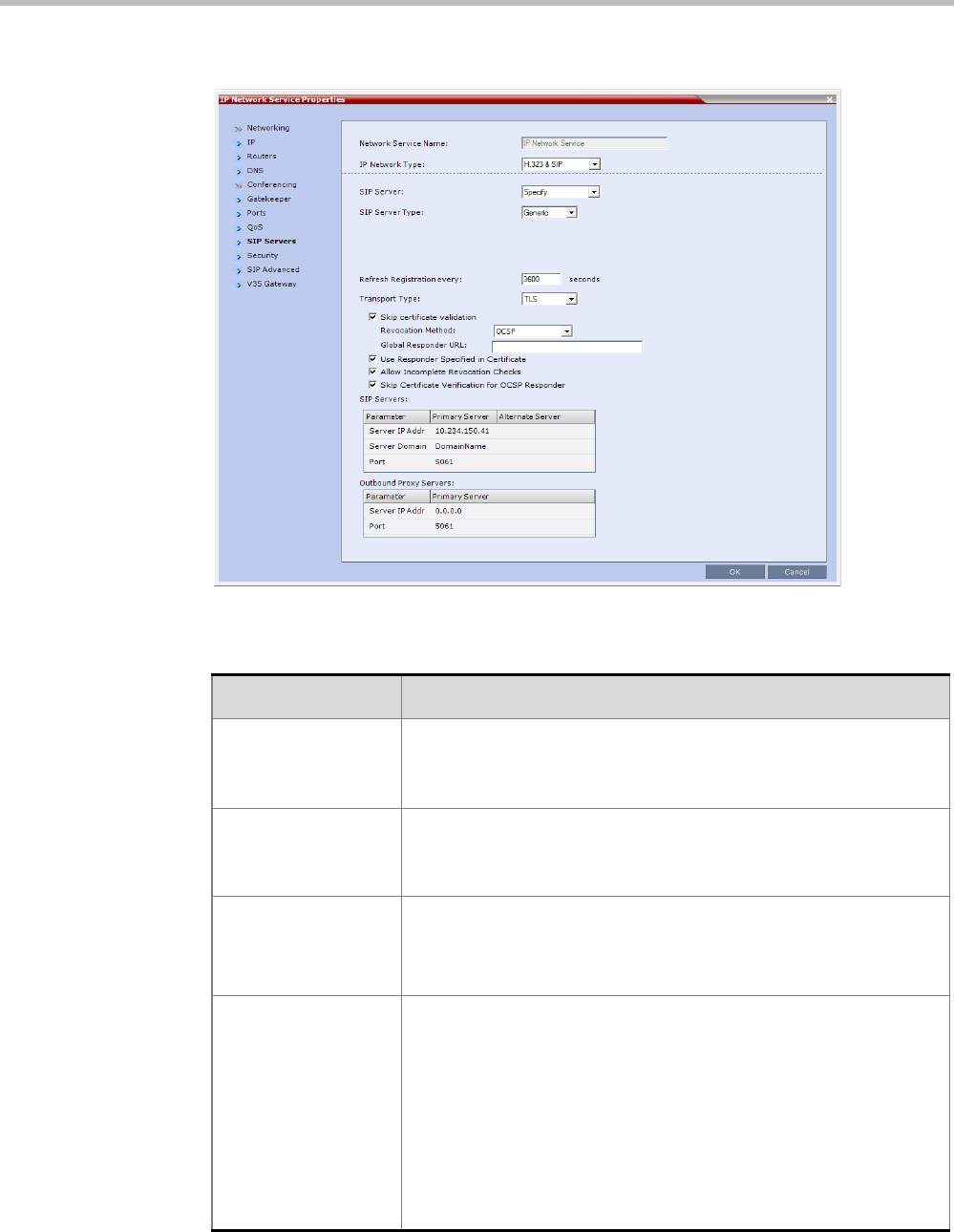
Polycom® RealPresence Collaboration ServerVirtual Edition Administrator’s Guide
15-16 Polycom, Inc.
12 Click the SIP Servers tab.
13 Modify the following fields:
Table 15-9 Default IP Network Service – SIP Servers
Field Description
SIP Server Select:
•Specify – to manually configure SIP servers.
•Off – if SIP servers are not present in the network.
SIP Server Type Select:
•Generic - for non Microsoft environments.
•Microsoft - for Microsoft environments.
Refresh Registration This defines the time in seconds, in which the Collaboration Server
refreshes it’s registration on the SIP server. For example, if “3600” is
entered the Collaboration Server will refresh it’s registration on the
SIP server every 3600 seconds.
Transport Type Select the protocol that is used for signaling between the
Collaboration Server and the SIP Server or the endpoints according
to the protocol supported by the SIP Server:
UDP – Select this option to use UDP for signaling.
TCP – Select this option to use TCP for signaling.
TLS – The Signaling Host listens on secured port 5061 only and all
outgoing connections are established on secured connections. Calls
from SIP clients or servers to non secured ports are rejected.
The following protocols are supported: TLS 1.0, SSL 2.0 and SSL
3.0.

Chapter 15-IP Network Services
Polycom, Inc. 15-17
Skip certificate
validation
Not supported in the RealPresence Collaboration Server Virtual
Edition.
Revocation Method The certificate revocation method:
•ONE (Default) - Certificate Revocation is not implemented.
•CRL - Requires at least one CRL file be installed, failing which an
error message, At least one CRL should be installed, is displayed.
Global Responder
URL
Not supported in the RealPresence Collaboration Server Virtual
Edition.
Use Responder
Specified in
Certificate
Not supported in the RealPresence Collaboration Server Virtual
Edition.
Allow Incomplete
Revocation Checks
•If the check box is checked and the CRL of the specific CA is not
loaded, all Certificates are the CA are not considered revoked.
•If the check box is unchecked and the CRL of the specific CA is
not loaded, all Certificates are the CA are considered revoked.
Skip Certificate
Validation for OSCP
Responder
Not supported in the RealPresence Collaboration Server Virtual
Edition.
SIP Servers: Primary / Backup Server Parameter
Server IP Address Enter the IP address of the preferred SIP server.
If DNS is used, you can enter the SIP server name.
Server Domain Name Enter the name of the domain that you are using for conferences, for
example:
user_name@domain name
The domain name is used for identifying the SIP server in the
appropriate domain according to the host part in the dialed string.
For example, when a call to EQ1@polycom.com reaches its
outbound proxy, this proxy looks for the SIP server in the
polycom.com domain, to which it will forward the call.
When this call arrives at the SIP server in polycom.com, the server
looks for the registered user (EQ1) and forwards the call to this Entry
Queue or conference.
Port Enter the number of the TCP or UDP port used for listening. The port
number must match the port number configured in the SIP server.
Default port is 5060.
Outbound Proxy Servers: Primary / Alternate Server Parameter
Server IP Address By default, the Outbound Proxy Server is the same as the SIP Server.
If they differ, modify the IP address of the Outbound Proxy and the
listening port number (if required).
If DNS is used, you can enter the SIP server name.
Port Enter the port number the outbound proxy is listening to.
The default port is 5060.
Table 15-9 Default IP Network Service – SIP Servers (Continued)
Field Description
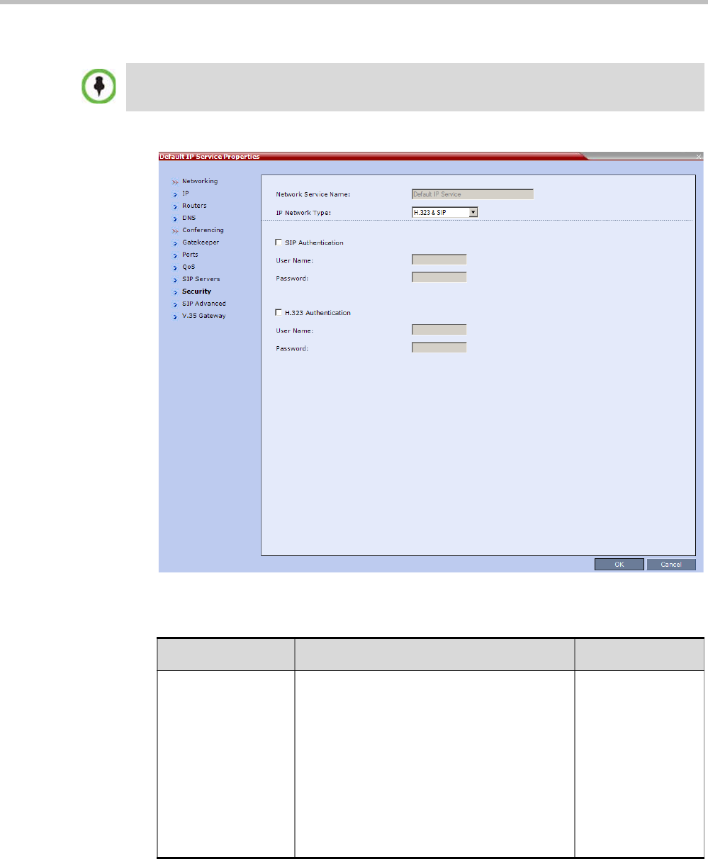
Polycom® RealPresence Collaboration ServerVirtual Edition Administrator’s Guide
15-18 Polycom, Inc.
14 Click the Security tab.
15 Modify the following fields:
When updating the parameters of the SIP Server in the IP Network Service - SIP Servers dialog box,
the Collaboration Server must be reset to implement the change.
Table 15-10 Default IP Network Service – Security (SIP Digest)
Field Description
SIP Authentication Click this check box to enable SIP proxy
authentication.
Select this check box only if the authentication
is enabled on the SIP proxy, to enable the
Collaboration Server to register with the SIP
proxy. If the authentication is enabled on the
SIP proxy and disabled on the RMX, calls will
fail to connect to the conferences.
Leave this check box cleared if the
authentication option is disabled on the SIP
proxy.
Chapter 15-IP Network Services
Polycom, Inc. 15-19
If the Authentication User Name and Authentication Password fields are left empty, the SIP
Digest authentication request is rejected. For registration without authentication, the
Collaboration Server must be registered as a trusted entity on the SIP server.
16 Click the OK button.
User Name Enter the user name the Collaboration Server
will use to authenticate itself with the SIP
proxy. This name must be defined in the SIP
proxy. These fields can
contain up to 20
ASCII characters.
Password Enter the password the Collaboration Server
will use to authenticate itself with the
gatekeeper. This password must be defined in
the SIP proxy.
H.323 Authentication Click this check box to enable H.323 server
authentication.
Select this check box only if the authentication
is enabled on the gatekeeper, to enable the
Collaboration Server to register with the
gatekeeper. If the authentication is enabled on
the gatekeeper and disabled on the RMX, calls
will fail to connect to the conferences.
Leave this check box cleared if the
authentication option is disabled on the
gatekeeper.
User Name Enter the user name the Collaboration Server
will use to authenticate itself with the
gatekeeper. This name must be defined in the
gatekeeper. These fields can
contain up to 64
ASCII characters.
Password Enter the password the Collaboration Server
will use to authenticate itself with the
gatekeeper. This password must be defined in
the gatekeeper.
Table 15-10 Default IP Network Service – Security (SIP Digest) (Continued)
Field Description
The fields in the SIP Advanced and V.35 Gateway tabs can be modified but their values will not be
applied.
When updating the parameters of the SIP Server in the IP Network Service - SIP Servers dialog box,
the Collaboration Server must be reset to implement the change.
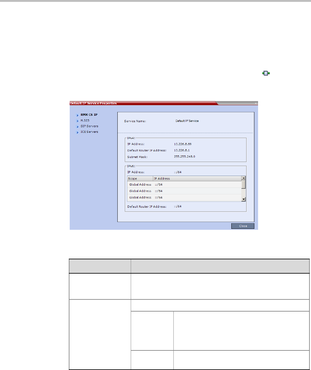
Polycom® RealPresence Collaboration ServerVirtual Edition Administrator’s Guide
15-20 Polycom, Inc.
IP Network Monitoring
The Signaling Monitor is the Collaboration Server entity used for monitoring the status of
external network entities such as the gatekeeper, DNS, SIP proxy and Outbound proxy and
their interaction with the MCU.
To monitor signaling status:
1In the Collaboration Server Management pane, click Signaling Monitor ().
2In the Signaling Monitor pane, double-click Default IP Service.
The IP Network Services Properties – RMX CS IP tab opens:
The RMX CS IP tab displays the following fields:
Table 15-11 IP Network Services Properties – RMX CS IP
Field Description
Service Name The name assigned to the IP Network Service by the Fast
Configuration Wizard.
Note: This field is displayed in all tabs.
IPv4 IP Address
Default
Router IP
Address
The IP address of the default router. The default
router is used whenever the defined static routers
are not able to route packets to their destination.
The default router is also used when host access is
restricted to one default router.
Subnet Mask The subnet mask of the MCU.
Default value: 255.255.255.0.
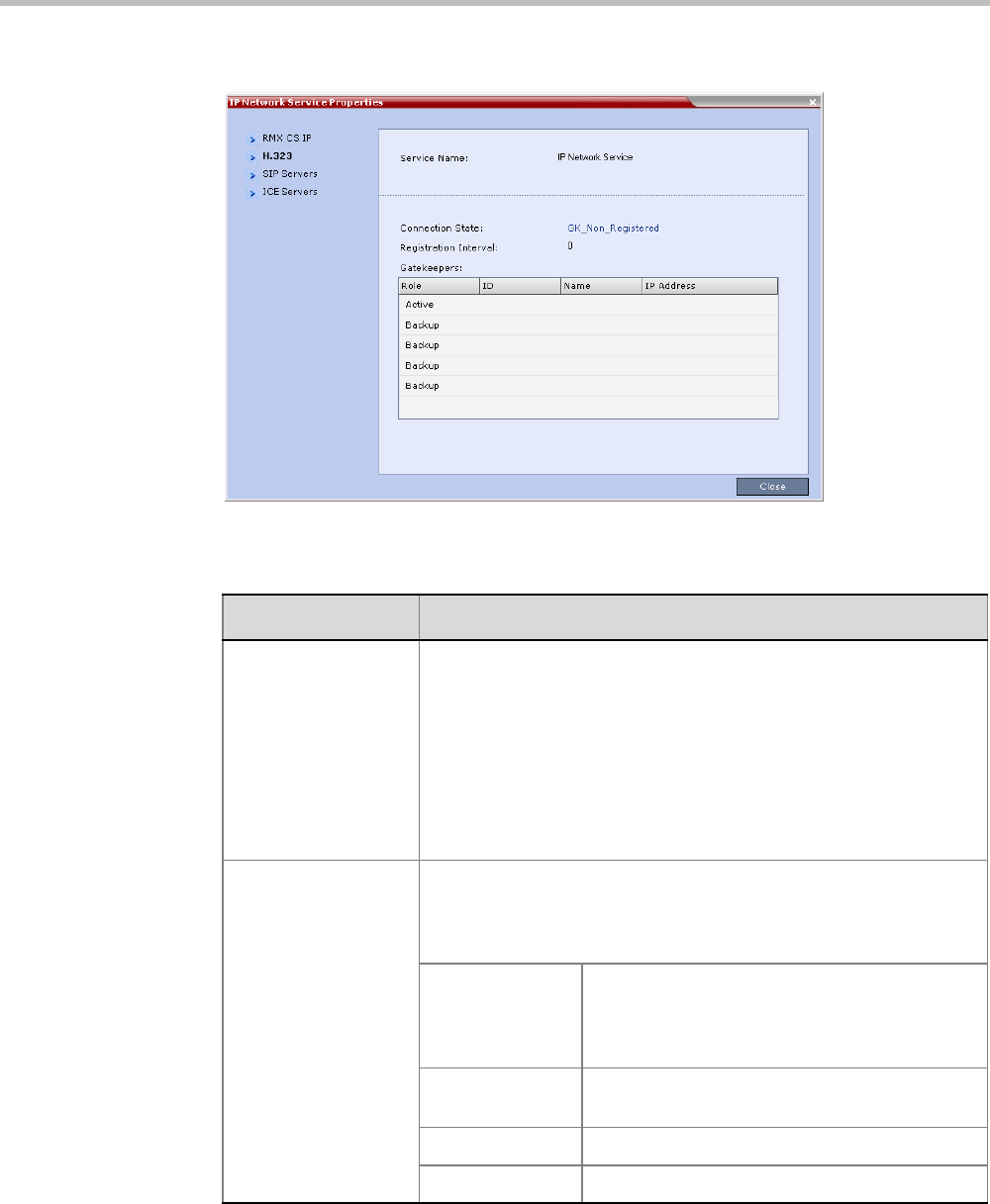
Chapter 15-IP Network Services
Polycom, Inc. 15-21
3Click the H.323 tab.
The H.323 tab displays the following fields:
Table 15-12 IP Network Services Properties – H.323
Field Description
Connection State The state of the connection between the Signaling Host and the
gatekeeper:
Discovery - The Signaling Host is attempting to locate the
gatekeeper.
Registration - The Signaling Host is in the process of registering with
the gatekeeper.
Registered - The Signaling Host is registered with the gatekeeper.
Not Registered - The registration of the Signaling Host with the
gatekeeper failed.
Registration Interval The interval in seconds between the Signaling Host’s registration
messages to the gatekeeper. This value is taken from either the IP
Network Service or from the gatekeeper during registration. The
lesser value of the two is chosen.
Role Active - The active gatekeeper.
Backup - The backup gatekeeper that can be
used if the connection to the preferred
gatekeeper fails.
ID The gatekeeper ID retrieved from the
gatekeeper during the registration process.
Name The gatekeeper’s host’s name.
IP Address The gatekeeper’s IP address.
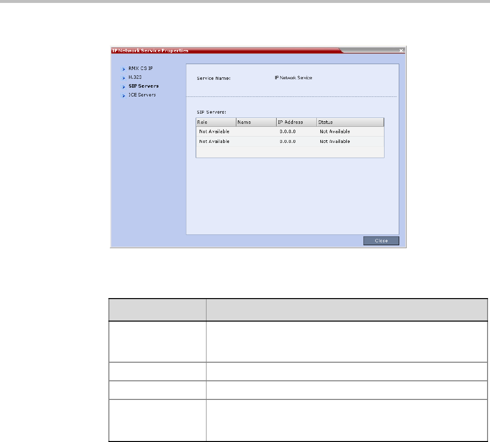
Polycom® RealPresence Collaboration ServerVirtual Edition Administrator’s Guide
15-22 Polycom, Inc.
4Click the SIP Servers tab.
The SIP Servers tab displays the following fields:
Table 15-13 IP Network Services Properties – SIP Servers
Field Description
Role Active -The default SIP Server is used for SIP traffic.
Backup -The SIP Server is used for SIP traffic if the preferred proxy
fails.
Name The name of the SIP Server.
IP Address The SIP Server's IP address.
Status The connection state between the SIP Server and the Signaling Host.
Not Available - No SIP server is available.
Auto - Gets information from DHCP, if used.
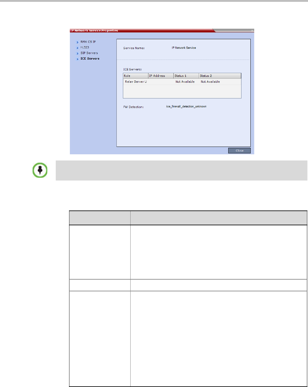
Chapter 15-IP Network Services
Polycom, Inc. 15-23
5Click the ICE Servers tab.
The ICE Servers tab displays the following fields:
ICE is not supported with RealPresence Collaboration Server Virtual Edition.
Table 15-14 IP Network Services Properties – ICE Servers
Field Description
Role The ICE Server’s role is displayed:
•STUN password server
•STUN Server UDP
•STUN Server TCP
•Relay Server UDP
•Relay Server TCP
IP Address The ICE Server’s IP Address.
Status 1/2/3/4 A status is displayed for each media card installed in the
Collaboration Server:
•Connection O.K.
•MS – register fail
•MS – subscribe fail
•MS – service fail
•Connection failed
•User/password failed
•Channel didn't receive any packets for 5 seconds
•Channel exceeded allotted bandwidth
•Unknown failure

Polycom® RealPresence Collaboration ServerVirtual Edition Administrator’s Guide
15-24 Polycom, Inc.
FW Detection The Firewall Detection status is displayed:
•Unknown
•UDP enabled
•TCP enabled
•Proxy -TCP is possible only through proxy
•Block – both UDP & TCP blocked
•None
Table 15-14 IP Network Services Properties – ICE Servers (Continued)
Field Description
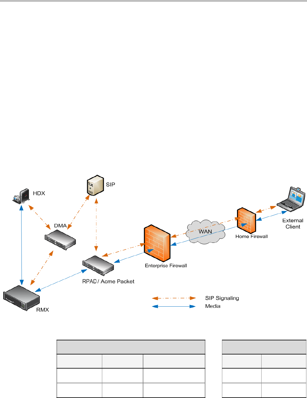
Chapter 15-IP Network Services
Polycom, Inc. 15-25
NAT (Network Address Translation) Traversal
NAT Traversal is a set of techniques enabling participants behind firewalls to connect to
conferences, hosted on the Collaboration Server, remotely using the internet.
Session Border Controller (SBC)
All signaling and media for both SIP and H.323 will be routed through an SBC.
The following SBC environments are supported:
•RealPresence Access Director (RPAD) - a Polycom SBC
•Acme Packet - a 3rd party SBC
•VBP - Polycom Video Border Proxy
Deployment Architectures
The following NAT Traversal topologies are given as examples. Actual deployments will
depend on user requirements and available infrastructure:
Remote Connection Using the Internet
The following Remote Connection call flow options are supported:
Table 15-15 Remote Connection
Enterprise Client CMA Client
Environment Registered SBC Registered Environment
SIP / H.323 Yes SAM / Acme Packet Yes SIP
SIP / H.323 No SAM / Acme Packet No SIP
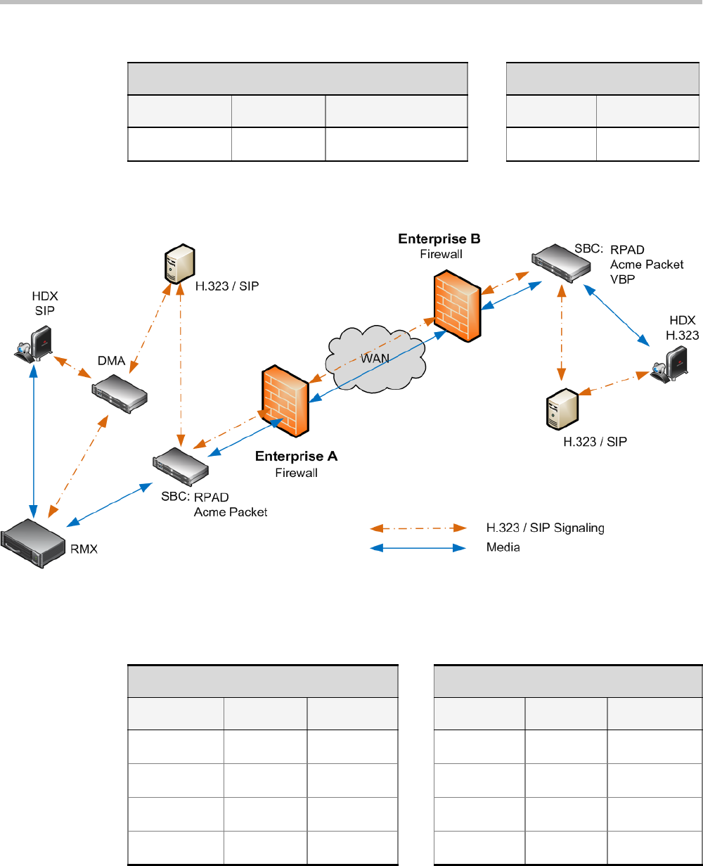
Polycom® RealPresence Collaboration ServerVirtual Edition Administrator’s Guide
15-26 Polycom, Inc.
Business to Business Connections
The following Business to Business connection call flow options are supported:
SIP / H.323 No SAM Only No H.323
Table 15-15 Remote Connection (Continued)
Enterprise Client CMA Client
Environment Registered SBC Registered Environment
Table 15-16 Business to Business Connection
Enterprise A Client Enterprise B Client
Environment Registered SBC SBC Registered Environment
H.323 Yes RPAD RPAD Yes H.323
H.323 Yes RPAD VBP Yes H.323
SIP Yes RPAD RPAD Yes H.323
SIP Yes Acme Packet Acme Packet Yes H.323

Chapter 15-IP Network Services
Polycom, Inc. 15-27
FW (Firewall) NAT Keep Alive
The Collaboration Server can be configured to send a FW NAT keep alive message at specific
Intervals for the RTP, UDP and BFCP channels.
This is necessary because port mappings in the firewall are kept open only if there is
network traffic in both directions. The firewall will only allow UDP packets into the
network through ports that have been used to send packets out.
By default the Collaboration Server sends a FW NAT Keep Alive message every 30 seconds.
As there is no traffic on the Content and FECC channels as a call begins, the firewall will not
allow any incoming packets from the Content and FECC channels in until the Collaboration
Server sends out the first of the FW NAT Keep Alive messages 30 seconds after the call starts.
If Content or FECC are required within the first 30 seconds of a call the FW NAT Keep Alive
Interval should be modified to a lower value.
To enable and modify FW NAT Keep Alive:
FW NAT Keep Alive is enabled in the New Profile - Advanced dialog box.
>> Select the FW NAT Keep Alive check box and if required, modify the Interval field within
the range of 1 - 86400 seconds.
System Configuration in SBC environments
In an environment that includes SAM (a Polycom SBC), to ensure that a RealPresence Mobile
endpoint can send content to a conference the value of the system flag
NUM_OF_INITIATE_HELLO_MESSAGE_IN_CALL_ESTABLISHMENT must be set to
at least 3.
For more details on modifying the values of system flags, see "Manually Adding and Deleting
System Flags” on page 20-12.
SIP Proxy Failover With Polycom® RealPresence
Distributed Media Application™ (DMA™) 7000 System
Collaboration Server systems that are part of a RealPresence DMA system environment can
benefit from the RealPresence DMA system’s SIP Proxy Failover functionality.
SIP Proxy Failover is supported in the RealPresence DMA system’s Local Clustering mode
with redundancy achieved by configuring two DMA servers to share a single virtual IP
address.
The virtual IP address is used by the Collaboration Server as the IP address of its SIP Proxy.
No additional configuration is needed on the Collaboration Server.
Should a SIP Proxy failure occur in one of the RealPresence DMA system servers:
• The other RealPresence DMA system server takes over as SIP Proxy.
• Ongoing calls may be disconnected.
• Previously ongoing calls will have to be re-connected using the original IP address,
registration and connection parameters.

Polycom® RealPresence Collaboration ServerVirtual Edition Administrator’s Guide
15-28 Polycom, Inc.
• New calls will connect using the original IP address, registration and connection
parameters.
RealPresence Collaboration Server Virtual Edition
Network Port Usage
The following table summarizes the port numbers and their usage in the RealPresence
Collaboration Server Virtual Edition:
Table 15-17 Collaboration Server Network Port Usage Summary
Connection
Type
Port
Number Protocol Description Configurable
HTTP 8080 TCP Management between the
Collaboration Server and
RealPresence Collaboration
Server Web Client.
No
HTTPS 4433 TCP Secured Management
between the Collaboration
Server and RealPresence
Collaboration Server Web
Client.
No
DNS 53 TCP Domain name server. Can be disabled in the
console Text User
Interface.
DHCP 68 TCP Dynamic Host Configuration
Protocol.
Can be disabled in the
console Text User
Interface.
SSH 22 TCP Secured shell. It is the
Collaboration Server terminal.
Can be disabled in the
console Text User
Interface.
NTP 123 UDP Network Time Protocol.
Enables access to a time
server on the network.
No
H.323 GK
RAS
1719 UDP Gatekeeper RAS messages
traffic.
No
H.323 Q.931 1720 -
incoming
;
49152-
59999 -
outgoing
TCP H.323 Q.931 call signaling.
Each outgoing call has a
separate port.
The port for each outgoing call
is allocated dynamically.
Yes - for outgoing
calls only.
It is configured in the
Fixed Ports section of
the IP service.

Chapter 15-IP Network Services
Polycom, Inc. 15-29
H.323 H.245 49152 -
59999
TCP H.245 control.
Each outgoing call has a
separate port.
The port for each outgoing call
is allocated dynamically. It can
be avoided by tunneling.
Yes - for outgoing
calls only.
It is configured in the
Fixed Ports section of
the IP service.
SIP server 5060
60000
UDP,
TCP
Connection to the SIP Server.
Sometimes port 60000 is used
when the system cannot reuse
the TCP port. This port can be
set in the Central signaling
(CS) configuration file.
Yes - in the IP service.
Alternative
SIP server
5060
60000
UDP,
TCP
Connection to the alternate
SIP Server.
Sometimes port 60000 is used
when the system cannot reuse
the TCP port. This port can be
set in the Central signaling
(CS) configuration file.
Yes - in the IP service.
SIP Outbound
proxy
5060
60000
UDP,
TCP
Connection to the SIP
outbound proxy.
Sometimes port 60000 is used
when the system cannot reuse
the TCP port. This port can be
set in the Central signaling
(CS) configuration file.
Yes - in the IP service.
Alternative
SIP Outbound
proxy
5060
60000
UDP,
TCP
Connection to the alternate
SIP outbound proxy.
Sometimes port 60000 is used
when the system cannot reuse
the TCP port. This port can be
set in the Central signaling
(CS) configuration file.
Yes - in the IP service.
SIP-TLS 60002 TCP Required for Binary Floor
Control Protocol (BFCP)
functionality for SIP
People+Content content
sharing.
No - port is not
opened if SIP
People+Content is
disabled.
RTP 49152 -
59999
UDP RTP media packets.
The ports are dynamically
allocated.
Yes - It is configured
in the Fixed Ports
section of the IP
service.
RTCP 49152 -
59999
UDP RTP control.
The ports are dynamically
allocated.
Yes - It is configured
in the Fixed Ports
section of the IP
service.
Table 15-17 Collaboration Server Network Port Usage Summary (Continued)
Connection
Type
Port
Number Protocol Description Configurable

Polycom® RealPresence Collaboration ServerVirtual Edition Administrator’s Guide
15-30 Polycom, Inc.
SIP -TLS 5061 TCP SIP -TLS for SIP server,
alternate SIP server,
outbound proxy and alternate
outbound proxy.
No
Table 15-17 Collaboration Server Network Port Usage Summary (Continued)
Connection
Type
Port
Number Protocol Description Configurable

Polycom, Inc. 16-1
16
IVR Services
Interactive Voice Response (IVR) is an application that allows participants to communicate
with the conferencing system via their endpoint’s input device (such as a remote control).
The IVR Service includes a set of voice prompts and a video slide used to automate the
participants connection to a conference or Entry Queue. It allows customization of menu
driven scripts and voice prompts to meet different needs and languages.
The IVR module includes two types of services:
• Conference IVR Service that is used with conferences
• Entry Queue IVR Service that is used with Entry Queues
The system is shipped with two default Conference IVR Services (one for the conferences
and the other for gateway calls) and one default Entry Queue IVR Service. The default
services include voice messages and video slides in English.
To customize the IVR messages and video slide perform the following operations:
• Record the required voice messages and create a new video slide. For more
information, see "Creating a Welcome Video Slide” on page 16-30.
• Optional. Add the language to the list of languages supported by the system.
• Upload the voice messages to the MCU (This can be done as part of the language
definition or during the IVR Service definition).
• Create the Conference IVR Service and upload the video slide, and if required any
additional voice messages.
• Optional. Create the Entry Queue IVR Service and upload the required video slide and
voice messages.
IVR Services List
You can view the currently defined Conference IVR and Entry Queue IVR Services in the
IVR Services list pane.
To view the IVR Services list:
1In the Collaboration Server Management pane, expand the Rarely Used list.
2Click the IVR Services () entry.
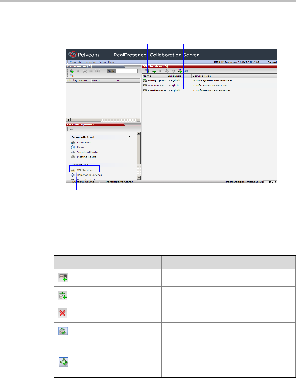
Polycom® RealPresence Collaboration ServerVirtual Edition Administrator’s Guide
16-2 Polycom, Inc.
The list pane displays the Conference IVR Services list and the total number of IVR
services currently defined in the system.
IVR Services Toolbar
The IVR Services toolbar provides quick access to the IVR Service definitions as follows:
IVR Toolbar IVR Services List Pane
Access to IVR Services
list and customization
Table 16-1 IVR Toolbar buttons
Button Button Name Descriptions
New Conference IVR Service To create a new Conference IVR Service.
New Entry Queue IVR Service To create a new Entry Queue IVR Service.
Delete Service Deletes the selected IVR service(s).
Set Default Conference IVR
Service
Sets the selected Conference IVR Service as default.
When creating a new conference Profile the default
IVR Service is automatically selected for the Profile
(but can be modified).
Set Default Entry Queue
Service
Sets the selected Entry Queue IVR Service as
default. When creating a new Entry Queue the default
Entry Queue IVR Service is automatically selected.
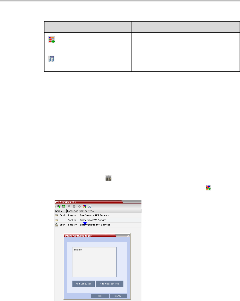
Chapter 16-IVR Services
Polycom, Inc. 16-3
Adding Languages
You can define different sets of audio prompts in different languages, allowing the
participants to hear the messages in their preferred language.
The Collaboration Server is shipped with a default language (English) and all the prompts and
messages required for the default IVR Services, conference and Entry Queues shipped with
the system.
You can add languages to the list of languages for which different messages are
downloaded to the MCU and IVR Services are created. This step is required before the
creation of additional IVR messages using languages that are different from English, or if
you want to download additional voice files to existing files in one operation and not during
the IVR service definition.
To add a language:
1In the Collaboration Server Management pane, expand the Rarely Used list.
2Click the IVR Services () entry.
3In the Conference IVR Services list, click the Add Supported Languages ( ) button.
The Supported Languages dialog box opens.
4Click the Add Language button.
Add Supported
Languages
Adds languages to the IVR module, enabling you to
download voice prompts and messages for various
languages.
Replace/Change Music File To replace the currently loaded music file that is used
to play background music, the MCU is shipped with a
default music file.
Table 16-1 IVR Toolbar buttons
Button Button Name Descriptions
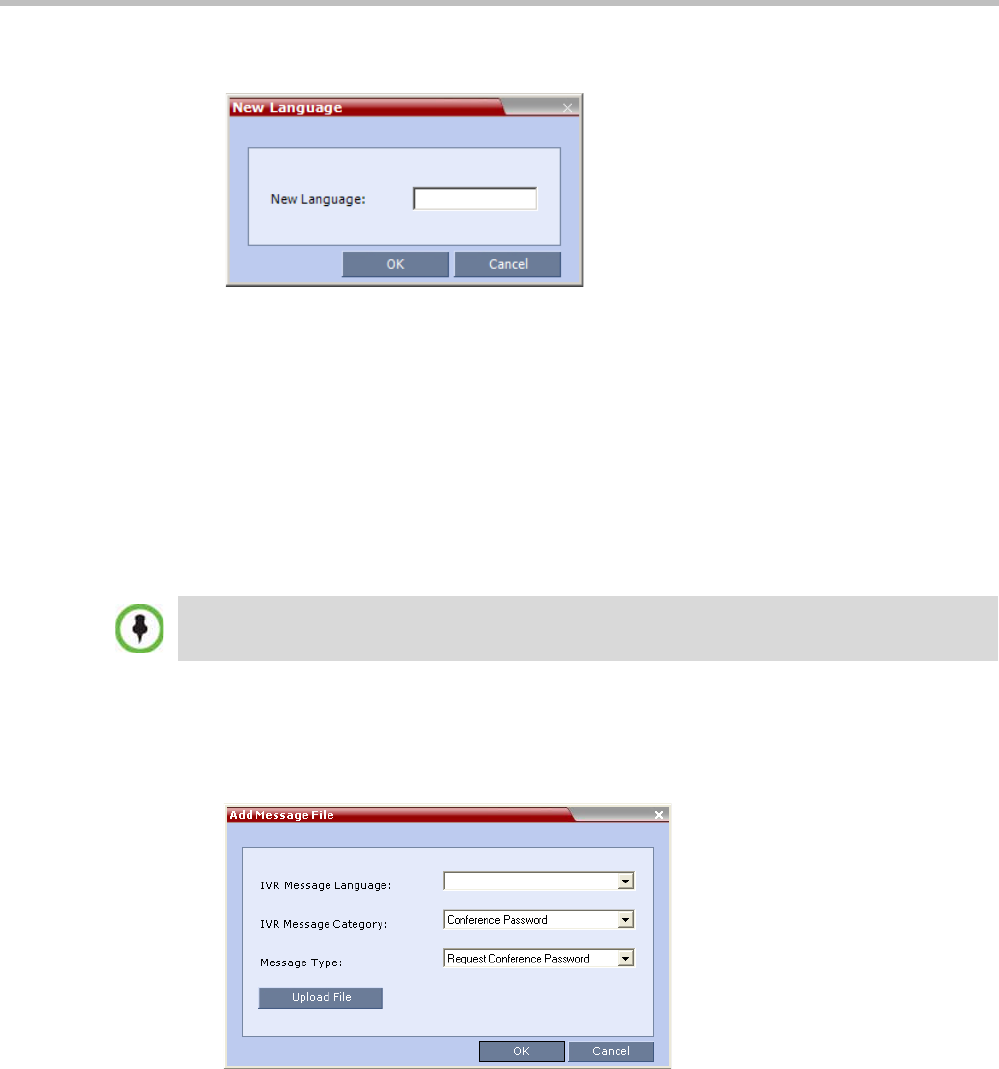
Polycom® RealPresence Collaboration ServerVirtual Edition Administrator’s Guide
16-4 Polycom, Inc.
The New Language dialog box opens.
5In the New Language box, enter the name of the new language. The language name can
be typed in Unicode and cannot start with a digit. Maximum field length is 31
characters.
6Click OK.
The new language is added to the list of Supported Languages.
Uploading a Message File to the Collaboration Server
You can upload audio files for the new language or additional files for an existing language
now, or you can do it during the definition of the IVR Service. In the latter case, you can skip
the next steps.
To upload messages to the MCU:
1To upload the files to the MCU, in the Supported Languages dialog box, click the Add
Message File button.
2The Add Message File dialog box opens.
Audio files are uploaded to the MCU one-by-one.
3In the IVR Message Language list, select the language for which the audio file will be
uploaded to the MCU.
4In the IVR Message Category list, select the category for which the audio file is uploaded.
5In the Message Type list, select the message type for which the uploaded message is to be
played. You can upload several audio files for each Message Type. Each file is
downloaded separately.
•Voice messages should not exceed 3 minutes.
•It is not recommended to upload more than 1000 audio files to the MCU memory.
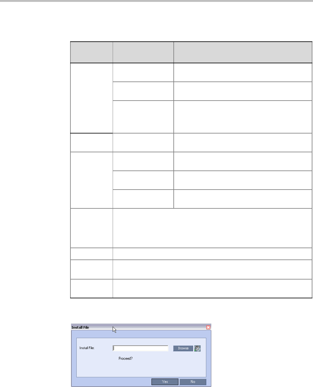
Chapter 16-IVR Services
Polycom, Inc. 16-5
Table 16-2 lists the Message Types for each category:
6Click Upload File to upload the appropriate audio file to the MCU.
The Install File dialog box opens.
7Enter the file name or click the Browse button to select the audio file to upload.
The Select Source File dialog box opens.
Table 16-2 IVR Message Types by Message Category
Message
Category Message Type Message
Conference
Password
Request Conference
Password
Requests the participant to enter the conference
password.
Request Conference
Password Retry
A participant who enters an incorrect password is
requested to enter it again.
Request Digit Requests the participant to enter any digit in order to
connect to the conference. Used for dial-out
participants to avoid answering machines in the
conference.
Welcome
Message
Welcome Message The first message played when the participant
connects to the conference or Entry Queue.
Conference
Chairperson
Request Chairperson
Identifier
Requests the participants to enter the chairperson
identifier key.
Request Chairperson
Password
Requests the participant to enter the chairperson
password.
Request Chairperson
Password Retry
When the participant enters an incorrect chairperson
password, requests the participant to enter it again.
General Messages played for system related event notifications, for example,
notification that the conference is locked. Upload the files for the voice
messages that are played when an event occurs during the conference. For
more information, see "Conference IVR Service Properties - General Voice
Messages” on page 16-11.
Billing Code Requests the chairperson to enter the conference Billing Code.
Roll Call Not applicable.
Conference
ID
Requests the participant to enter the required Conference ID to be routed to
the destination conference.
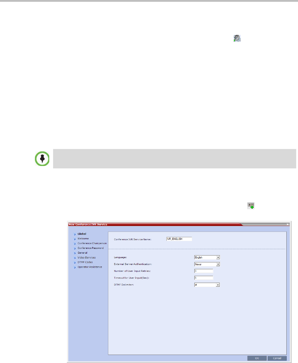
Polycom® RealPresence Collaboration ServerVirtual Edition Administrator’s Guide
16-6 Polycom, Inc.
8Select the appropriate *.wav audio file, and then click the Open button.
The name of the selected file is displayed in the Install field in the Install File dialog box.
9Optional. You can play a .wav file by selecting the Play button ( ).
10 Click Yes to upload the file to the MCU.
The system returns to the Add Message File dialog box.
11 Repeat step 6 to 10 for each additional audio file to be uploaded to the MCU.
12 Once all the audio files are uploaded to the MCU, close the Add Message File dialog box
and return to the Add Language dialog box.
13 Click OK.
Defining a New Conference IVR Service
The Collaboration Server is shipped with two default Conference IVR Services and all its
audio messages and video slide. You can define new Conference IVR Services or modify the
default Conference IVR Service.
Defining a New Conference IVR Service
To define a new Conference IVR Service:
1On the IVR Services toolbar, click the New Conference IVR Service () button.
The New Conference IVR Service - Global dialog box opens.
Up to 40 IVR Services (Conference IVR Services and Entry Queue IVR Services) can be defined for
a single Collaboration Server unit.
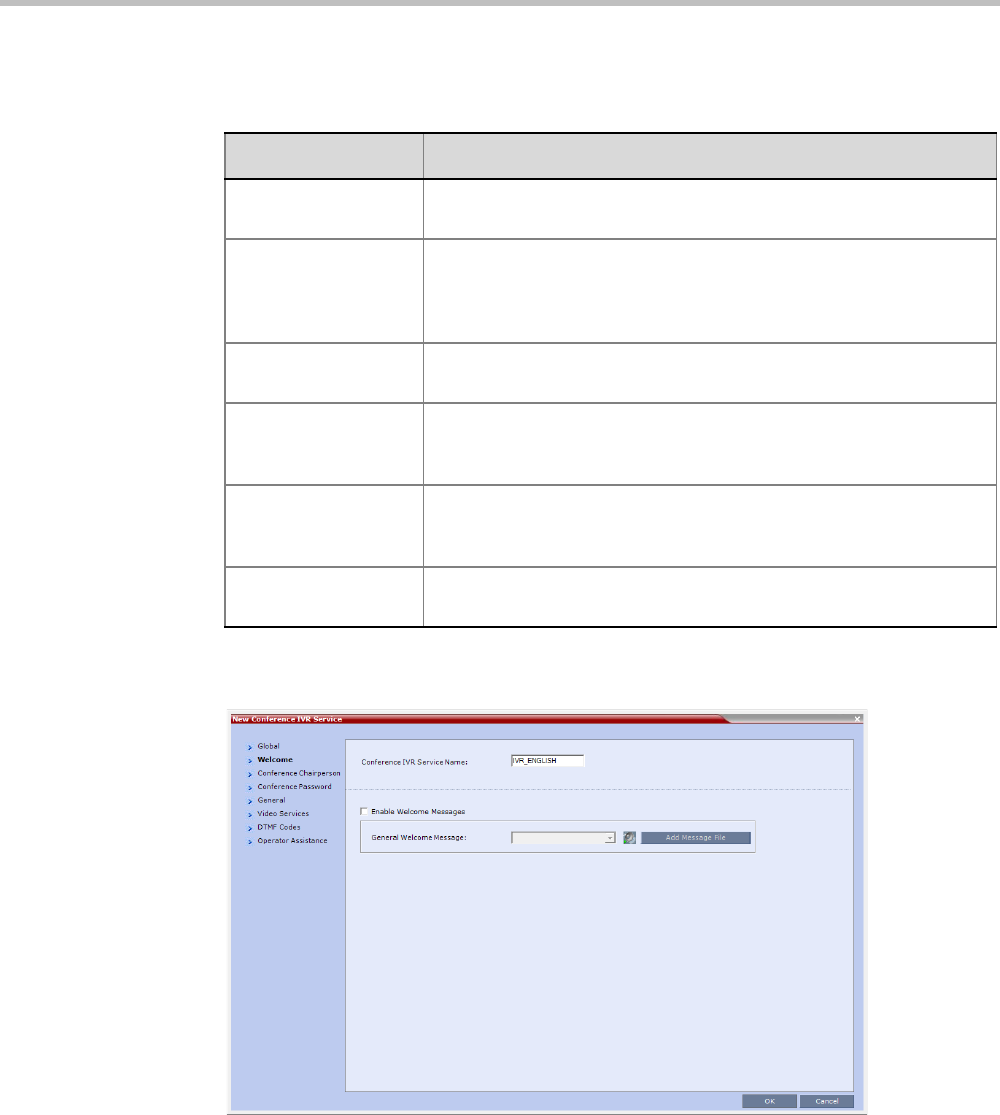
Chapter 16-IVR Services
Polycom, Inc. 16-7
2Define the following parameters:
3Click the Welcome tab.
The New Conference IVR Service - Welcome dialog box opens.
4Select the Enable Welcome Messages check box to define the system behavior when
the participant enters the Conference IVR queue. When participants access a conference
through an Entry Queue, they hear messages included in both the Entry Queue Service
and Conference IVR Service. To avoid playing the Welcome Message twice, disable the
Welcome Message in the Conference IVR Service.
5Select the General Welcome Message, to be played when the participant enters the
conference IVR queue.
Table 16-3 Conference IVR Service Properties - Global Parameters
Field/Option Description
Conference IVR
Service Name
Enter the name of the Conference IVR Service. The maximum field
length is 20 characters and may be typed in Unicode.
Language For IVR Select the language of the audio messages and prompts from the list
of languages defined in the Supported languages. The default
language is English. For more information, see "Adding Languages”
on page 16-3.
External Server
Authentication
Number of User Input
Retries
Enter the number of times the participant will be able to respond to
each menu prompt before being disconnected from the conference.
Range is between 1-4, and the default is 3.
Timeout for User
Input (Sec)
Enter the duration in seconds that the system will wait for the
participant’s input before prompting for another input. Range is
between 1-10, and the default value is 5 seconds.
DTMF Delimiter Enter the key that indicates the last input key. Possible values are the
pound (#) and star (*) keys. The default is #.
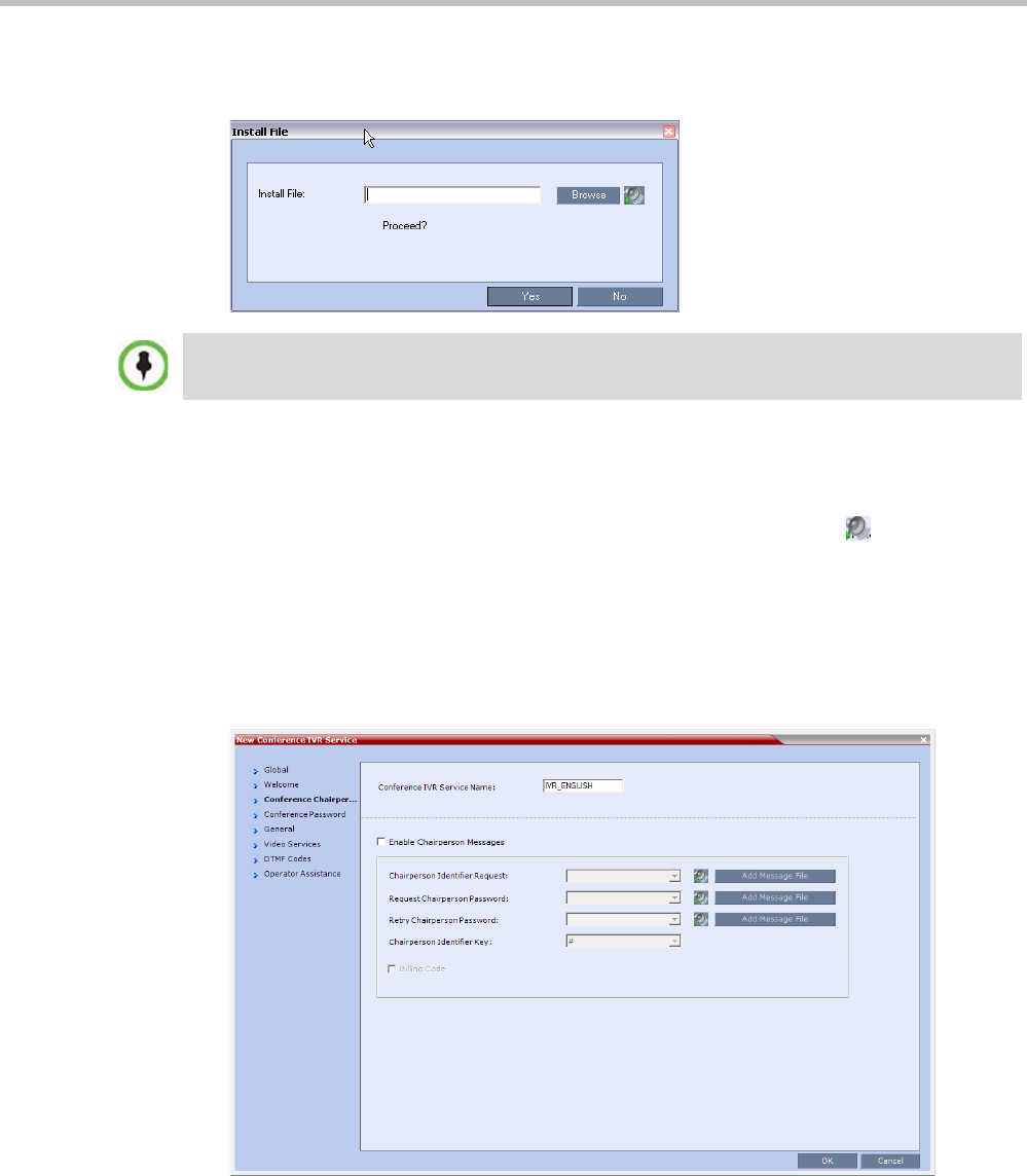
Polycom® RealPresence Collaboration ServerVirtual Edition Administrator’s Guide
16-8 Polycom, Inc.
6To upload an audio file for an IVR message, click Add Message File.
The Install File dialog box opens.
aClick the Browse button to select the audio file (*.wav) to upload.
The Select Source File dialog box opens.
bSelect the appropriate *.wav audio file and then click the Open button.
cOptional. You can play a .wav file by selecting the Play button ( ).
dIn the Install File dialog box, click Yes to upload the file to the MCU memory.
The Done dialog box opens.
eOnce the upload is complete, click OK and return to the IVR dialog box. The new
audio file can now be selected from the list of audio messages.
7Click the Conference Chairperson tab.
The New Conference IVR Service - Conference Chairperson dialog box opens.
The Collaboration Server unit is bundled with default audio IVR message files. To upload a
customized audio file, see "Creating Audio Prompts and Video Slides” on page 16-27.
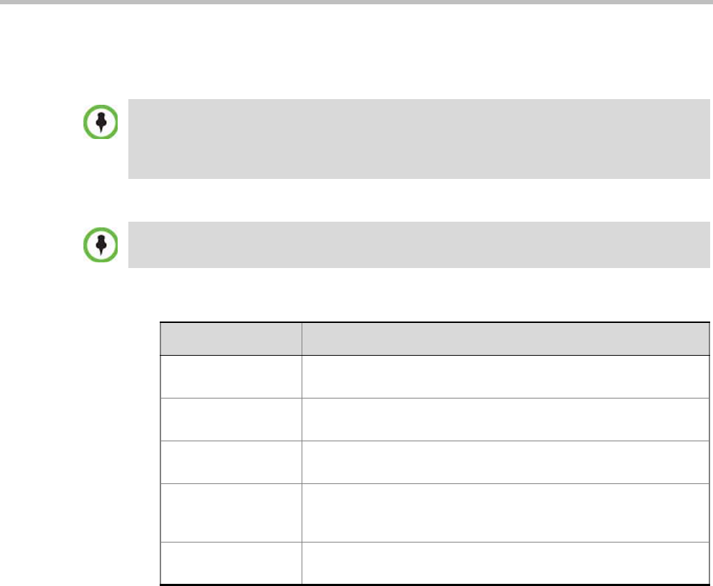
Chapter 16-IVR Services
Polycom, Inc. 16-9
8Select the Enable Chairperson Messages check box to enable the chairperson
functionality. If this feature is disabled, participants are not able to connect as the
chairperson.
9Select the various voice messages and options for the chairperson connection.
10 Click the Conference Password tab.
When both Conference Password and Chairperson Password options are enabled and defined, the
system first plays the prompt "Enter conference password". However, if the participant enters the
chairperson password, the participant becomes the chairperson.
To play the prompt requesting the Chairperson password, "For conference chairperson services...",
do not select the Enable Password Messages option.
If the files were not uploaded prior to the definition of the IVR Service or if you want to add new audio
files, click Add Message File to upload the appropriate audio file to the Collaboration Server.
Table 16-4 New Conference IVR Service Properties - Conference Chairperson Options and
Messages
Field/Option Description
Chairperson Identifier
Request
Select the audio file that requests the participants to enter the key
that identifies them as the conference chairperson.
Request Chairperson
Password
Select the audio file that prompts the participant for the chairperson
password.
Retry Chairperson
Password
Select the audio file that prompts participants to re-enter the
chairperson password if they enter it incorrectly.
Chairperson Identifier
Key
Enter the key to be used for identifying the participant as a
chairperson.
Possible keys are: pound key (#) or star (*).
Billing Code The prompt requesting the chairperson billing code selected in the
General tab.
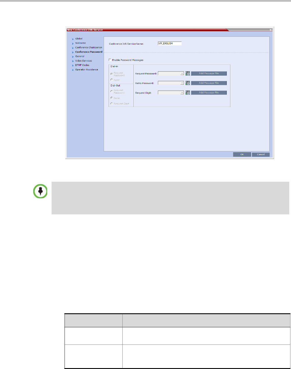
Polycom® RealPresence Collaboration ServerVirtual Edition Administrator’s Guide
16-10 Polycom, Inc.
The New Conference IVR Service - Conference Password dialog box opens.
11 Select the Enable Password Messages check box to request the conference password
before moving the participant from the conference IVR queue to the conference.
12 Select the MCU behavior for password request for Dial-in and Dial-out participant
connections.
Select the required system behavior as follows:
—Request password - The system requests the participant to enter the conference
password.
—None - The participant is moved to the conference without any password request.
—Request Digit - The system requests the participant to enter any key. This option is
used mainly for dial-out participants and to prevent an answering machine from
entering the conference.
13 Select the various audio messages that will be played in each case.
When both Conference Password and Chairperson Password are enabled and defined, the system
first plays the prompt "Enter conference password". However, if the participant enters the
chairperson password, the participant becomes the chairperson.
To play the prompt requesting the Chairperson password, "For conference chairperson services...",
do not select the Enable Password Messages option.
Table 16-5 New Conference IVR Service Properties - Conference Password Parameters
Option Description
Request Password Select the audio file that prompts the participant for the conference
password.
Retry Password Select the audio file that requests the participant to enter the
conference password again when failing to enter the correct
password.
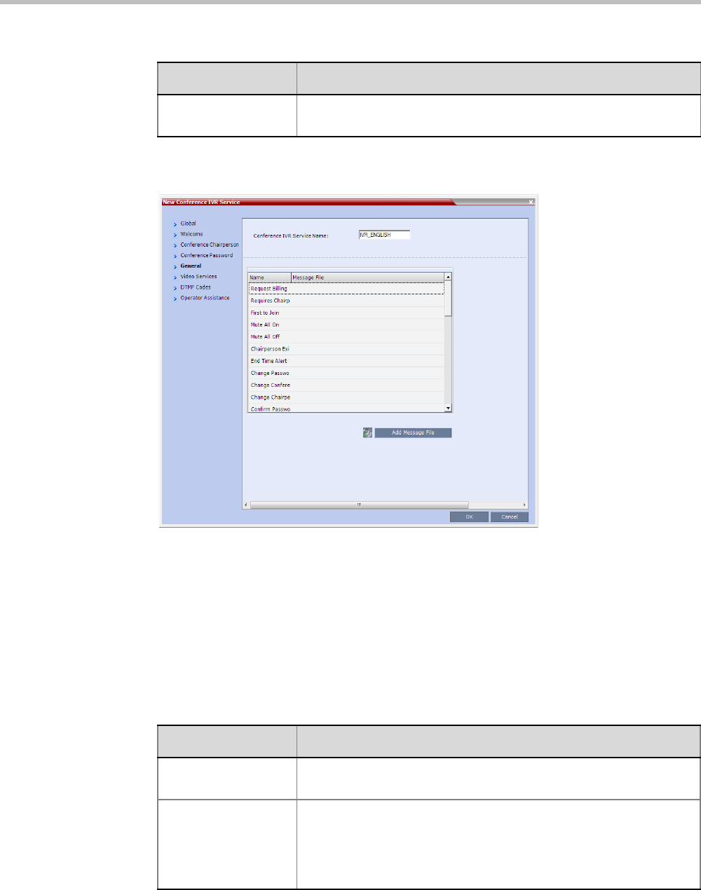
Chapter 16-IVR Services
Polycom, Inc. 16-11
14 Click the General tab.
The New Conference IVR Service - General dialog box opens.
The General dialog box lists messages that are played during the conference. These
messages are played when participants or the conference chairperson perform various
operations or when a change occurs.
15 To assign the appropriate audio file to the message type, click the appropriate table
entry, in the Message File column. A drop-down list is enabled.
16 From the list, select the audio file to be assigned to the event/indication.
17 Repeat steps 15 and 16 to select the audio files for the required messages.
The following types of messages and prompts can be enabled:
Request Digit Select the audio file that prompts the participant to press any key
when the Request Digit option is selected.
Table 16-5 New Conference IVR Service Properties - Conference Password Parameters
Option Description
Table 16-6 Conference IVR Service Properties - General Voice Messages
Message Type Description
Blip on Cascade Link Indicates that the link to the cascaded conference connected
successfully.
Chairperson Exit Informs all the conference participants that the chairperson has left
the conference, causing the conference to automatically terminate
after a short interval.
Note: This message is played only when the Requires Chairperson
option is selected in the Conference Profile - IVR dialog box.

Polycom® RealPresence Collaboration ServerVirtual Edition Administrator’s Guide
16-12 Polycom, Inc.
Chairperson Help
Menu
A voice menu is played upon a request from the chairperson, listing
the operations and their respective DTMF codes that can be
performed by the chairperson. The playback can be stopped any
time.
Note: If you modify the default DTMF codes used to perform various
operations, the default voice files for the help menus must be
replaced.
Change Chairperson
Password
Requests the participant to enter a new chairperson password when
the participant is attempting to modify the chairperson password.
Change Conference
Password
Requests the participant to enter a new conference password when
the participant is attempting to modify the conference password.
Change Password
Failure
A message played when the participant enters an invalid password,
for example when a password is already in use.
Change Passwords
Menu
This voice menu is played when the participants requests to change
the conference password. This message details the steps required to
complete the procedure.
Conference is Locked This message is played to participants attempting to join a Secured
conference.
Conference is
Secured
This message is played when the conference status changes to
Secure as initiated by the conference chairperson or participant
(using DTMF code *71).
Conference is
unsecured
This message is played when the conference status changes to
Unsecured as initiated by the conference chairperson or participant
(using DTMF code #71).
Confirm Password
Change
Requests the participant to re-enter the new password.
Enter Destination ID Prompts the calling participant for the destination number. Default
message prompts the participant for the conference ID (same
message as in the Entry Queue IVR Service).
Note: This option is not available in SVC conferences and for SVC
participants in mixed CP and SVC conferences.
First to Join Informs the participant that he or she is the first person to join the
conference.
Incorrect Destination
ID
If the participant entered an incorrect conference ID (in gateway calls
it is the destination number), requests the participant to enter the
number again.
Note: This option is not available in SVC conferences and for SVC
participants in mixed CP and SVC conferences.
Maximum Number of
Participants
Exceeded
Indicates the participant cannot join the destination conference as the
maximum allowed number of participants will be exceeded.
Table 16-6 Conference IVR Service Properties - General Voice Messages (Continued)
Message Type Description

Chapter 16-IVR Services
Polycom, Inc. 16-13
18 Click the Video Services tab.
Mute All Off This message is played to the conference to inform all participants
that they are unmuted (when Mute All is cancelled).
Mute All On Informs all participants that they are muted, with the exception of the
conference chairperson.
Note: This message is played only when the Mute All Except Me
option is activated.
No Video Resources
Audio Only.
Informs the participant of the lack of Video Resources in the
Collaboration Server and that he/she is being connected as Audio
Only.
Participant Help
Menu
A voice menu that is played upon request from a participant, listing
the operations and their DTMF codes that can be performed by any
participant.
Password Changed
Successfully
A message is played when the password was successfully changed.
Recording Failed This message is played when the conference recording initiated by
the chairperson or the participant (depending on the configuration)
fails to start.
Recording in
Progress
This message is played to participant joining a conference that is
being recorded indicating the recording status of the conference.
Request Billing Code Requests the participant to enter a code for billing purposes.
Requires Chairperson The message is played when the conference is on hold and the
chairperson joins the conference. For this message to be played the
Conference Requires Chairperson option must be selected in the
Conference Profile - IVR dialog box.
Self Mute A confirmation message that is played when participants request to
mute their line.
Self Unmute A confirmation message that is played when participants request to
unmute their line.
Table 16-6 Conference IVR Service Properties - General Voice Messages (Continued)
Message Type Description
The Roll Call and Tone Notification options are disabled in SVC and mixed CP and SVC
conferences.
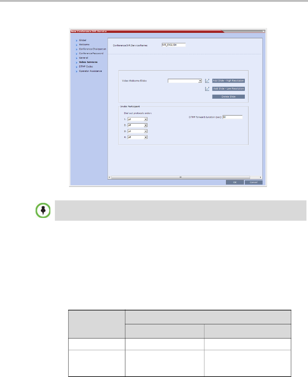
Polycom® RealPresence Collaboration ServerVirtual Edition Administrator’s Guide
16-14 Polycom, Inc.
The New Conference IVR Service - Video Services dialog box opens.
In addition to the low and high resolution slides included in the default slide set,
customized low and high resolution slides are supported.
The following guidelines apply:
—Two customized slides can be loaded per IVR Service:
• A low resolution slide, to be used with low resolution endpoints.
• A high resolution slide, to be used with high resolution endpoints.
Table 16-7 summarizes the recommended input slide formats and the resulting
slides that are generated:
—The source images for the high resolution slides must be in *.bmp or *.jpg format.
The Click&View and Invite Participants features are disabled in SVC and mixed CP and SVC
conferences.
Table 16-7 IVR Slide - Input / Output Formats
Slide Resolution
Format
Input Slides Generated Slides
High HD720p (16:9) HD720p
Low 4CIF (4:3)
or
CIF (4:3)
4SIF
SIF
CIF

Chapter 16-IVR Services
Polycom, Inc. 16-15
—If the uploaded slides are not of the exact SD or HD resolution, an error message is
displayed and the slides are automatically cropped or enlarged to the right size.
—If a slide that is selected in an IVR Service is deleted, a warning is displayed listing
the IVR Services in which it is selected. If deleted, it will be replaced with a default
Collaboration Server slide.
—The generated slides are not deleted if the system is downgraded to a lower
software version.
—The first custom source file uploaded, whatever its format, is used to generate both
high and low resolution custom slides. High resolution source files uploaded after
the first upload will be used to generate and replace high resolution custom slides.
Likewise, low resolution source files uploaded after the first upload will be used to
generate and replace low resolution custom slides.
—If there are two custom source files in the folder, one high resolution, one low
resolution, and a new high resolution custom source file is uploaded, new high
resolution custom slides are created. The existing low resolution custom slides are
not deleted.
—If there are two custom source files in the folder, one high resolution, one low
resolution, and a new low resolution custom source file is uploaded, new low
resolution custom slides are created. The existing high resolution custom slides are
not deleted.
19 Define the following parameters:
20 If the video slide file was not uploaded to the MCU prior to the IVR Service definition,
click the:
—Add Slide - Low Resolution button to upload a Low Resolution Slide.
—Add Slide - High Resolution button to upload a High Resolution Slide.
Table 16-8 New Conference IVR Service Properties - Video Services Parameters
Video Services Description
Video Welcome Slide Select the Low Resolution and High Resolution video slides to be
displayed when participants connect to the conference.
To view any slide, click the Preview Slide () button.
Notes:
•When using one of the default Polycom slides, the slide will be
displayed in the resolution defined in the profile, i.e. CIF, SD,
HD 720p
•Customized H.261 slides are not supported.
Invite Participant Not applicable.
Note: The Invite Participant feature is not available in SVC
conferences and for SVC participants in mixed CP and SVC
conferences.
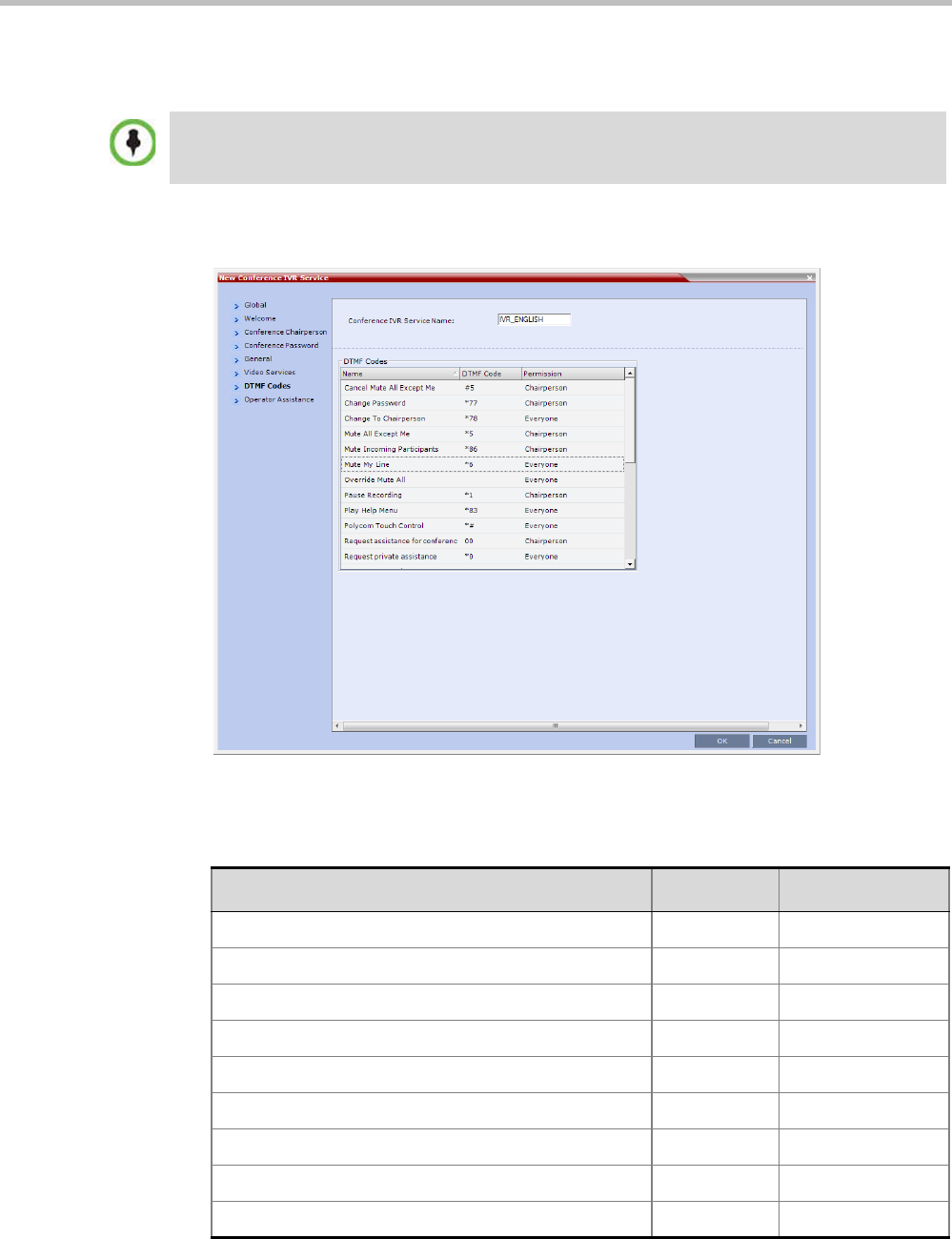
Polycom® RealPresence Collaboration ServerVirtual Edition Administrator’s Guide
16-16 Polycom, Inc.
The Install File dialog box opens. The uploading process is similar to the uploading of
audio files. For more information, see step 6 on page 16-8.
21 Click the DTMF Codes tab.
The New Conference IVR Service - DTMF Codes dialog box opens.
• This dialog box lists the default DTMF codes for the various functions that can be
performed during the conference by all participants or by the chairperson.
•The video slide must be in a .jpg or .bmp file format. For more information, see "Creating a
Welcome Video Slide” on page 16-30.
•Customized H.261 slides are not supported.
Table 16-9 New Conference IVR Service Properties - DTMF Codes
Operation DTMF String Permission
Mute My Line *6 Everyone
Unmute My Line #6 Everyone
Mute All Except Me *5 Chairperson
Cancel Mute All Except Me #5 Chairperson
Change Password *77 Chairperson
Mute Incoming Participants *86 Chairperson
Unmute Incoming Participants #86 Chairperson
Play Help Menu *83 Everyone
Terminate Conference *87 Chairperson
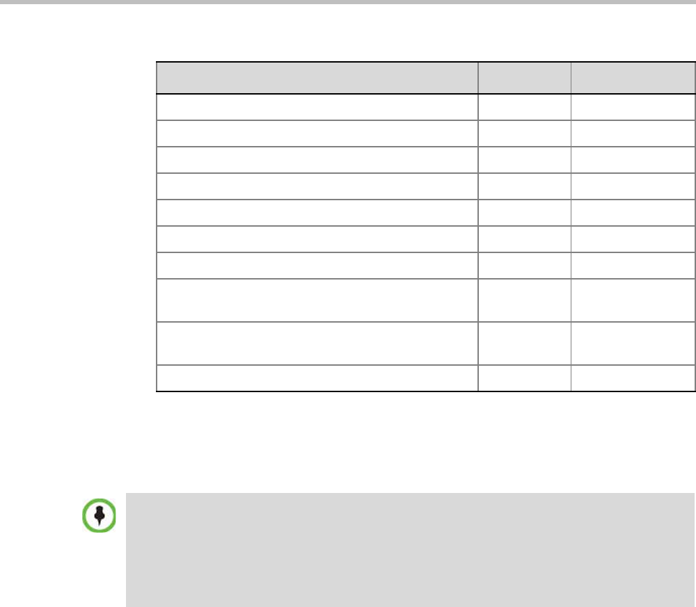
Chapter 16-IVR Services
Polycom, Inc. 16-17
22 To modify the DTMF code or permission:
aIn the DTMF Code column, in the appropriate entry enter the new code.
bIn the Permission column, select from the list who can use this feature (Everyone or
just the Chairperson).
Change To Chairperson *78 Everyone
Override Mute All Configurable Everyone
Start Recording *3 Chairperson
Stop Recording *2 Chairperson
Pause Recording *1 Chairperson
Secure Conference *71 Chairperson
Unsecured Conference #71 Chairperson
Request individual assistance
Note: This option is not available for SVC participants.
*0 Everyone
Request assistance for conference
Note: This option is not available for SVC participants.
00 Chairperson
Request to Speak 99 Everyone
Table 16-9 New Conference IVR Service Properties - DTMF Codes
Operation DTMF String Permission
By default, the Secure, Unsecure Conference and Show Number of Participants options are enabled
in the Conference IVR Service. These options can be disabled by removing their codes from the
Conference IVR Service.
•To disable the Text Indication option in the DTMF Code column, clear the DTMF code (*88) of
Show Number of Participants from the table.
•To disable the Secure Conference options, in the DTMF Code column, clear the DTMF codes of
both Secured Conference (*71) and Unsecured Conference (#71) from the table.
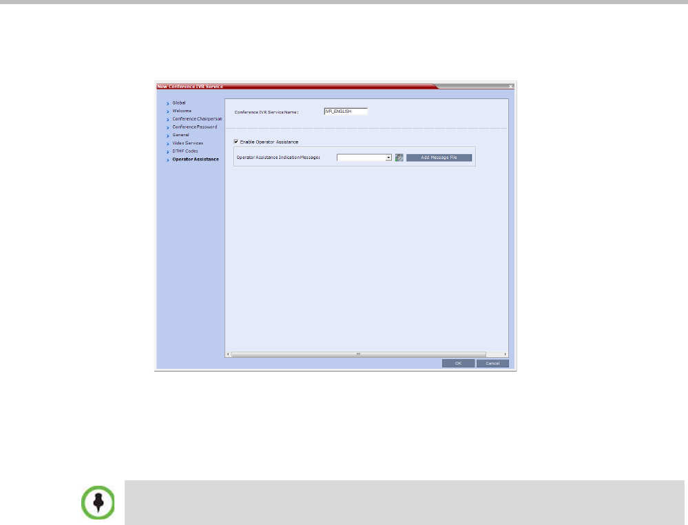
Polycom® RealPresence Collaboration ServerVirtual Edition Administrator’s Guide
16-18 Polycom, Inc.
23 Click the Operator Assistance tab.
The Operator Assistance dialog box opens.
24 Select Enable Operator Assistance to enable operator assistance when the participant
requires or requests help during the connection process to the conference or during the
conference.
25 In the Operator Assistance Indication Message field, select the audio message to be played
when the participant requests or is waiting for the operator’s assistance.
26 Click OK to complete the IVR Service definition.
The new Conference IVR Service is added to the IVR Services list.
Change to Chairperson
Regular participants can request to become the conference chairperson using the
appropriate DTMF code (default: *78), which enabled them to perform operations
designated for chairpersons only.
The Change to Chairperson via the DTMF code (default: *78) is executed only if the
following settings were configured for the MCU and the conference:
•In the Conference IVR Service - Conference Chairperson dialog box, select the Enable
Chairperson Messages check box, and select the appropriate voice messages.
For more information, see Polycom® RealPresence Collaboration Server Virtual Edition
Administrator’s Guide, "New Conference IVR Service Properties - Conference Chairperson
Options and Messages” on page 16-9.
• When starting a new conference or defining a new Meeting Room, define the
Chairperson Password in the conference General dialog box.
For more information, see "Creating a New Meeting Room” on page 6-4.
If the audio file was not uploaded prior to the definition of the IVR Service or if you want to add new
audio files, click Add Message File to upload the appropriate audio file to the Collaboration Server.
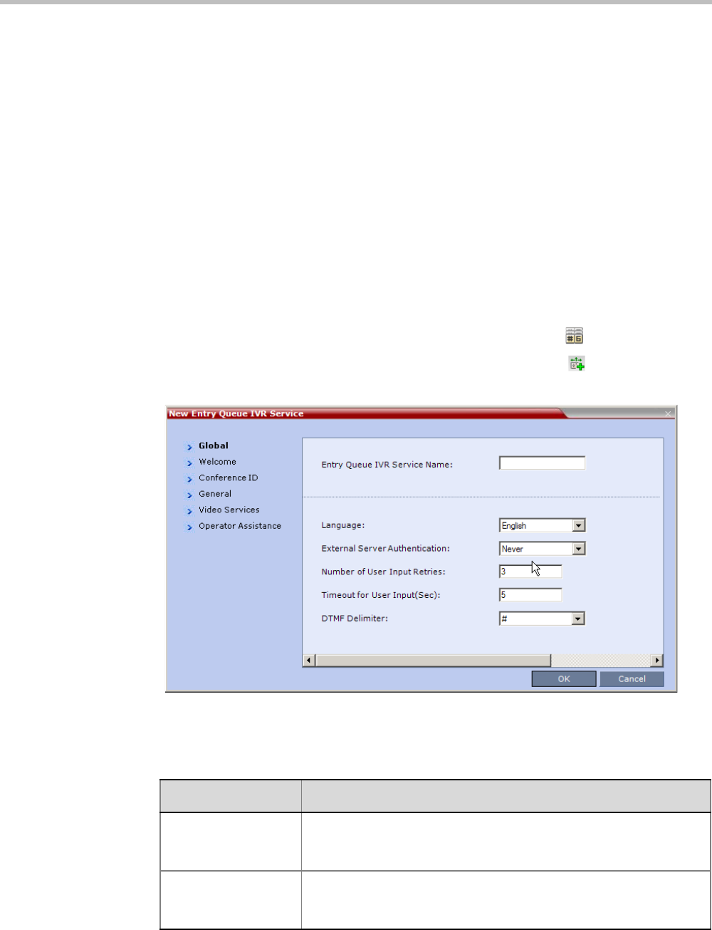
Chapter 16-IVR Services
Polycom, Inc. 16-19
Entry Queue IVR Service
An Entry Queue (EQ) is a routing lobby for conferences. Participants are routed to the
appropriate conference according to the conference ID they enter.
An Entry Queue IVR Service must be assigned to the Entry Queue to enable the voice
prompts and video slide guiding the participants through the connection process.
An Entry Queue IVR Service is a subset of an IVR Service. You can create different Entry
Queue Services for different languages and personalized voice messages.
The Collaboration Server is shipped with a default Entry Queue IVR Service and all its audio
messages and video slide. You can define new Entry Queue IVR Services or modify the
default Entry Queue IVR Service.
Defining a New Entry Queue IVR Service
To set up a new Entry Queue IVR Service:
1In the Collaboration Server Management pane, click IVR Services ().
2In the IVR Services list, click the New Entry Queue IVR Service () button.
The New Entry Queue IVR Service - Global dialog box opens.
3Fill in the following parameters:
Table 16-10 Entry Queue IVR Service Properties - Global Parameters
Option Description
Entry Queue Service
Name
(Mandatory) Enter the name of the Entry Queue Service. The name
can be typed in Unicode. Maximum field length is 80 ASCII
characters.
Language Select the language in which the Audio Messages and prompts will
be heard. The languages are defined in the Supported Languages
function.
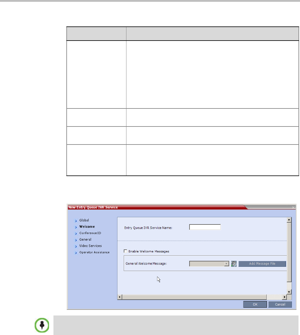
Polycom® RealPresence Collaboration ServerVirtual Edition Administrator’s Guide
16-20 Polycom, Inc.
4Click the Welcome tab.
The New Entry Queue IVR Service - Welcome dialog box opens.
5Define the appropriate parameters. This dialog box contains options that are identical
to those in the Conference IVR Service - Welcome Message dialog box. For more
information about these parameters, see Table 16-4 on page 16-9.
External Server
Authentication
This option is used for Ad Hoc conferencing, to verify the participant’s
permission to initiate a new conference. For a detailed description
see Appendix D: "Ad Hoc Conferencing and External Database
Authentication” on page D-1.
Select one of the following options:
•None to start a new conference without verifying with an external
database the user right to start it.
•Conference ID to verify the user’s right to start a new conference
with an external database application using the conference ID.
Number of User Input
Retries
Enter the number of times the participant is able to respond to each
menu prompt before the participant is disconnected from the MCU.
Timeout for User
Input (Sec.)
Enter the duration in seconds that the system waits for input from the
participant before it is considered as an input error.
DTMF Delimiter The interaction between the caller and the system is done via touch-
tone signals (DTMF codes). Enter the key that will be used to indicate
a DTMF command sent by the participant or the conference
chairperson. Possible keys are the pound key (#) or star (*).
Table 16-10 Entry Queue IVR Service Properties - Global Parameters (Continued)
Option Description
If the files were not uploaded prior to the definition of the IVR Service or if you want to add new audio
files, click Add Message File to upload the appropriate audio file to the Collaboration Server.
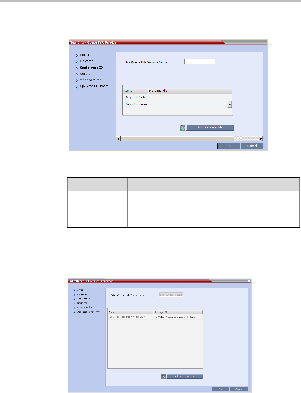
Chapter 16-IVR Services
Polycom, Inc. 16-21
6Click the Conference ID tab.
The New Entry Queue IVR Service - Conference ID dialog box opens.
7Select the voice messages:
8Assign an audio file to each message type, as follows:
—In the Message File column, click the table entry, and then select the appropriate
audio message.
9Click the General tab.
The New Entry Queue IVR Service - General dialog box opens.
Table 16-11 Entry Queue IVR Service Properties - Conference ID
Field/Option Description
Request Conference
ID
Prompts the participant for the conference ID.
Retry Conference ID When the participant entered an incorrect conference ID, requests
the participant to enter the ID again.
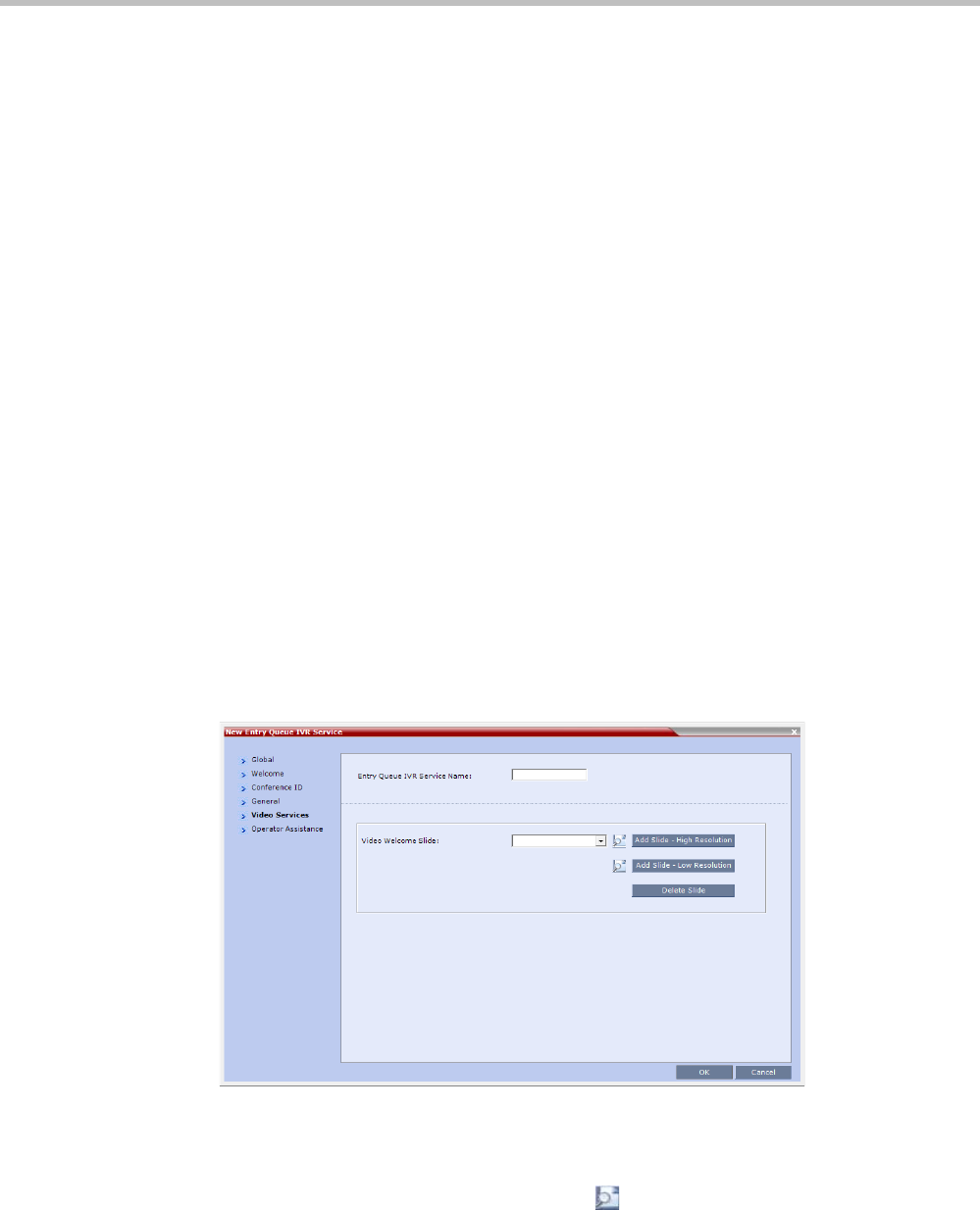
Polycom® RealPresence Collaboration ServerVirtual Edition Administrator’s Guide
16-22 Polycom, Inc.
The administrator can enable an audio message that informs the participant of the lack
of Video Resources in the Collaboration Server and that he/she is being connected as Audio
Only. The message states: All video resources are currently in use. Connecting using audio
only.
The following guidelines apply:
—The IVR message applies to video participants only. Audio Only participants will
not receive the message.
—Only H.323 and SIP participants receive the audio message.
—The audio message is the first message after the call is connected, preceding all
other IVR messages.
—The message is called No Video Resources-Audio Only and the message file (.wav) is
called No video resources audio only.wav.
—The audio message must be added to the Conference and Entry Queue IVR Services
separately.
—The IVR message can be enabled/disabled by the administrator using the
ENABLE_ NO_VIDEO_RESOURCES_ AUDIO_ONLY_MESSAGE System Flag
in system.cfg.
Possible values: YES / NO, default: YES
If you wish to modify the flag value, the flag must be added to the System Configuration
file. For more information see the "Modifying System Flags” on page 20-1.
10 Enter the message Name and Message File name for the Audio Only message:
—Message Name: No Video Resources-Audio Only
—Message File name: No_Video_Resources_Audio_Only.wav
11 Click the Video Services tab.
The New Entry Queue IVR Service - Video Services dialog box opens.
12 In the Video Welcome Slide list, select the video slide that will be displayed to
participants connecting to the Entry Queue. The slide list includes the video slides that
were previously uploaded to the MCU memory.
13 To view any slide, click the Preview Slide ( ) button.
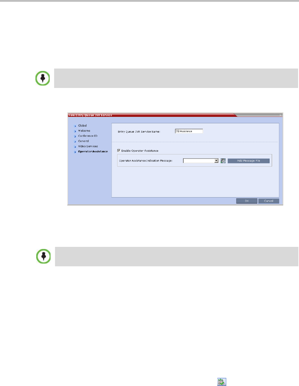
Chapter 16-IVR Services
Polycom, Inc. 16-23
14 If the video slide file was not uploaded to the MCU prior to the IVR Service definition,
click the:
—Add Slide - Low Resolution button to upload a Low Resolution Slide.
—Add Slide - High Resolution button to upload a High Resolution Slide.
The Install File dialog box opens. The uploading process is similar to the uploading of
audio files. For more information, see step 6 on page 16-8.
15 Click the Operator Assistance tab.
The Operator Assistance dialog box opens.
16 Select Enable Operator Assistance to enable operator assistance when the participant
requires or requests help during the connection process.
17 In the Operator Assistance Indication Message field, select the audio message to be played
when the participant requests or is waiting for operator’s assistance.
18 Click OK to complete the Entry Queue Service definition.
The new Entry Queue IVR Service is added to the IVR Services list. For more
information, see "IVR Services List” on page 16-1.
Setting a Conference IVR Service or Entry Queue IVR Service as the
Default Service
The first Conference IVR Service and Entry Queue IVR Service are automatically selected by
default. The IVR Services (Conference and Entry Queue) shipped with the system are also
set as default. If additional Conference IVR Services and Entry Queue IVR Services are
defined, you can set another service as the default for each service type.
To select the default Conference IVR Service:
>> In the IVR Services list, select the Conference IVR Service to be defined as the default,
and then click the Set Default Conference IVR Service () button.
The video slide must be in a .jpg or .bmp file format. For more information, see "Creating a Welcome
Video Slide” on page 16-30.
If the audio file was not uploaded prior to the definition of the IVR Service or if you want to add new
audio files, click Add Message File to upload the appropriate audio file to the Collaboration Server.
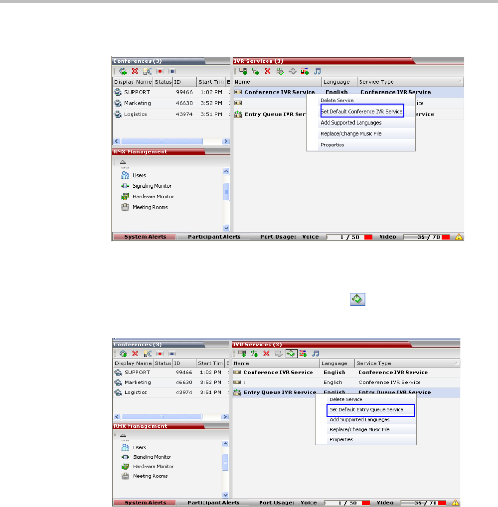
Polycom® RealPresence Collaboration ServerVirtual Edition Administrator’s Guide
16-24 Polycom, Inc.
Alternatively, in the IVR Services list, right-click the Conference IVR Service and then
select Set Default Conference IVR Service.
The IVR Service is displayed in bold, indicating that it is the current default service.
To select the Default Entry Queue IVR Service:
>> In the IVR Services list, select the Entry Queue IVR Service to be defined as the default,
and then click Set Default Entry Queue IVR Service () button.
Alternatively, in the Conference IVR Services list, right-click the Entry Queue IVR Service
and then select Set Default Entry Queue IVR Service.
The default Entry Queue IVR Service is displayed in bold, indicating that it is the
current default service.

Chapter 16-IVR Services
Polycom, Inc. 16-25
Modifying the Conference or Entry Queue IVR Service Properties
You can modify the properties of an existing IVR Service, except the service name and
language.
To modify the properties of an IVR Service:
1In the Collaboration Server Management pane, click IVR Services.
2In the IVR Services list, Click the IVR Service to modify.
For more information about the tabs and options of this dialog box, see "Defining a New
Conference IVR Service” on page 16-6.
3Modify the required parameters or upload the required audio files.
4Click OK.
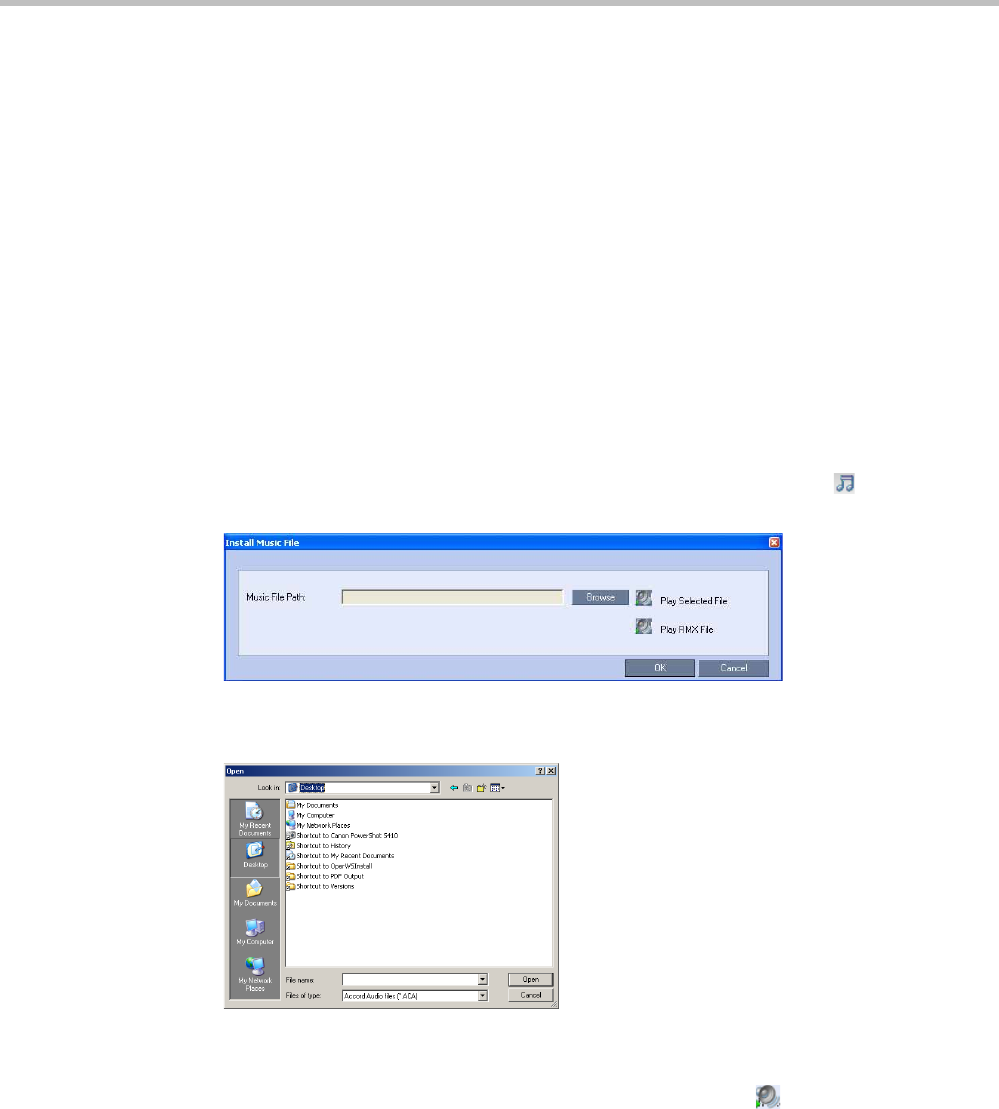
Polycom® RealPresence Collaboration ServerVirtual Edition Administrator’s Guide
16-26 Polycom, Inc.
Replacing the Music File
The Collaboration Server is shipped with a default music file that is played when participants
are placed on hold, for example, while waiting for the chairperson to connect to the
conference (if the conference requires a chairperson), or when a single participant is
connected to the conference. You can replace the default music file with your own recorded
music.
Music file guidelines:
• The file must be in *.wav format.
• Music length cannot exceed one hour.
• The music recording must be in the range of (-12dB) to (-9dB).
Adding a Music File
To replace the Music file:
1In the Collaboration Server Management pane, click IVR Services.
2In the IVR Services list toolbar, click the Replace/Change Music File ( ) button.
The Install Music File window opens.
3Click the Browse button to select the audio file (*.wav) to upload.
The Open dialog box opens.
4Select the appropriate audio *.wav file and then click the Open button.
The selected file name is displayed in the Install Music File dialog box.
5Optional. You can play the selected file by clicking the Play () button.
aClick Play Selected File to play a file on your computer.
bClick Play Collaboration Server File to play a file already uploaded on the
Collaboration Server.
6In the Install Music File dialog box, click OK to upload the file to the MCU.
The new file replaces the previously uploaded file and this file is used for all
background music played by the MCU.
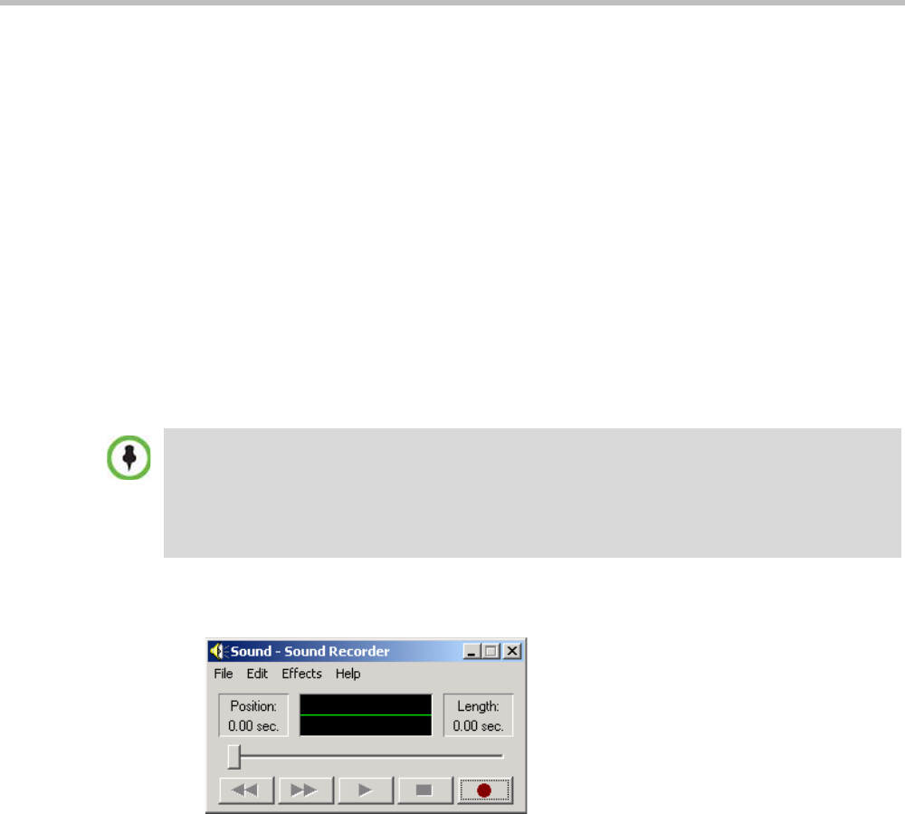
Chapter 16-IVR Services
Polycom, Inc. 16-27
Creating Audio Prompts and Video Slides
The Collaboration Server is shipped with default voice messages (in WAV format) and video
slides that are used for the default IVR services. You can create your own video slides and
record the voice messages for different languages or customize them to your needs.
Recording an Audio Message
To record audio messages, use any sound recording utility available in your computer or
record them professionally in a recording studio. Make sure that recorded message can be
saved as a Wave file (*.wav format) and that the recorded format settings are as defined in
steps 4 and 5 on page 16-28. The files are converted into the Collaboration Server internal
format during the upload process.
This section describes the use of the Sound Recorder utility delivered with Windows 95/98/
2000/XP.
To define the format settings for audio messages:
1On your PC, click Start > Programs > Accessories > Entertainment > Sound Recorder.
The Sound–Sound Recorder dialog box opens.
2To define the recording format, click File > Properties.
The Properties for Sound dialog box opens.
•The format settings for audio messages need to be set only once. The settings will then be
applied to any new audio messages recorded.
•The utility or facility used to record audio messages must be capable of producing audio files
with the formats and attributes as shown in the following procedure, namely, PCM, 16.000kHz,
16Bit, Mono.
Windows® XP® Sound Recorder is one of the utilities that can be used.
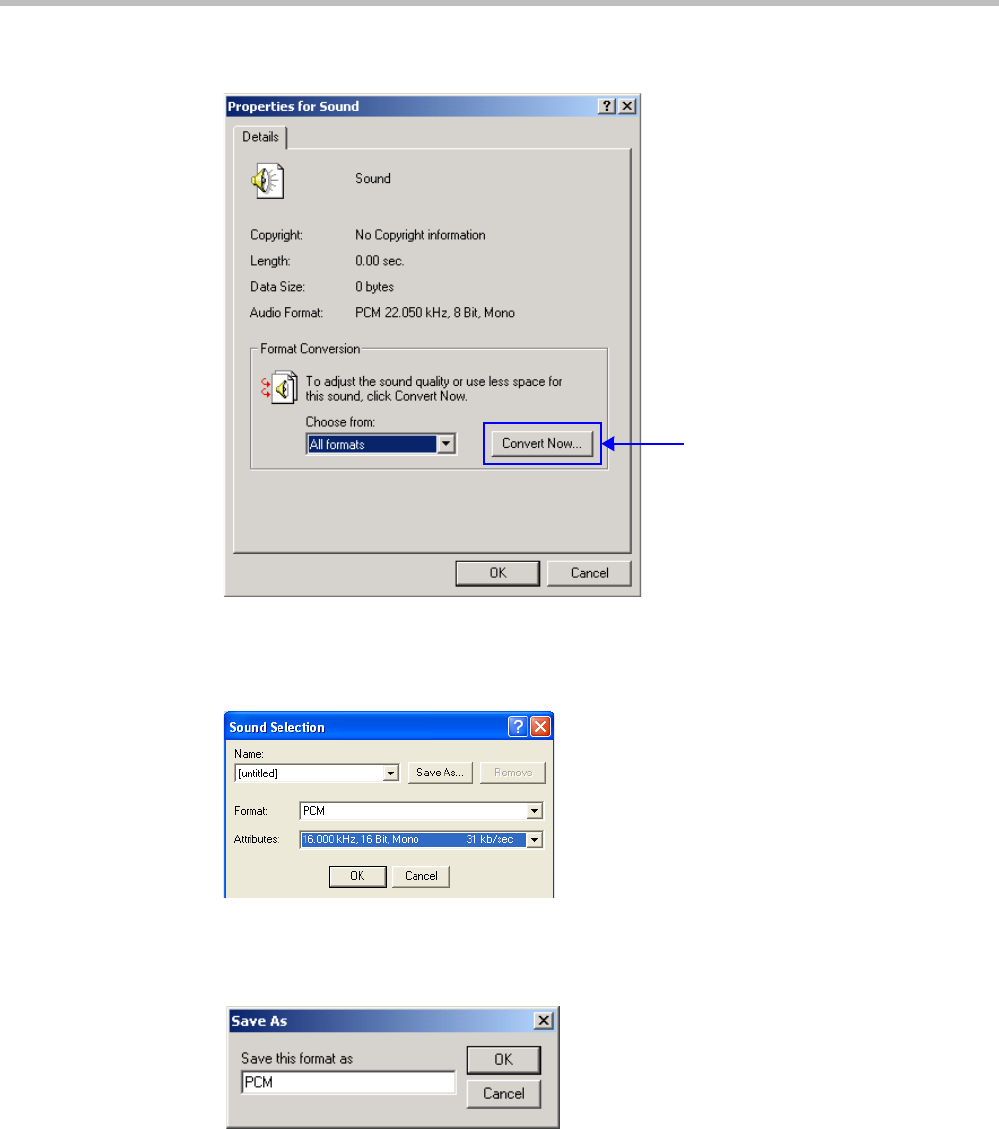
Polycom® RealPresence Collaboration ServerVirtual Edition Administrator’s Guide
16-28 Polycom, Inc.
3Click the Convert Now button.
The Sound Selection dialog box opens.
4In the Format field, select PCM.
5In the Attributes list, select 16.000 kHz, 16Bit, Mono.
6To save this format, click the Save As button.
The Save As dialog box opens.
7Select the location where the format will reside, enter a name and then click OK.
The system returns to the Sound Selection dialog box.
8Click OK.
The system returns to the Properties for Sound dialog box.
9Click OK.
The system returns to the Sound–Sound Recorder dialog box. You are now ready to
record your voice message.
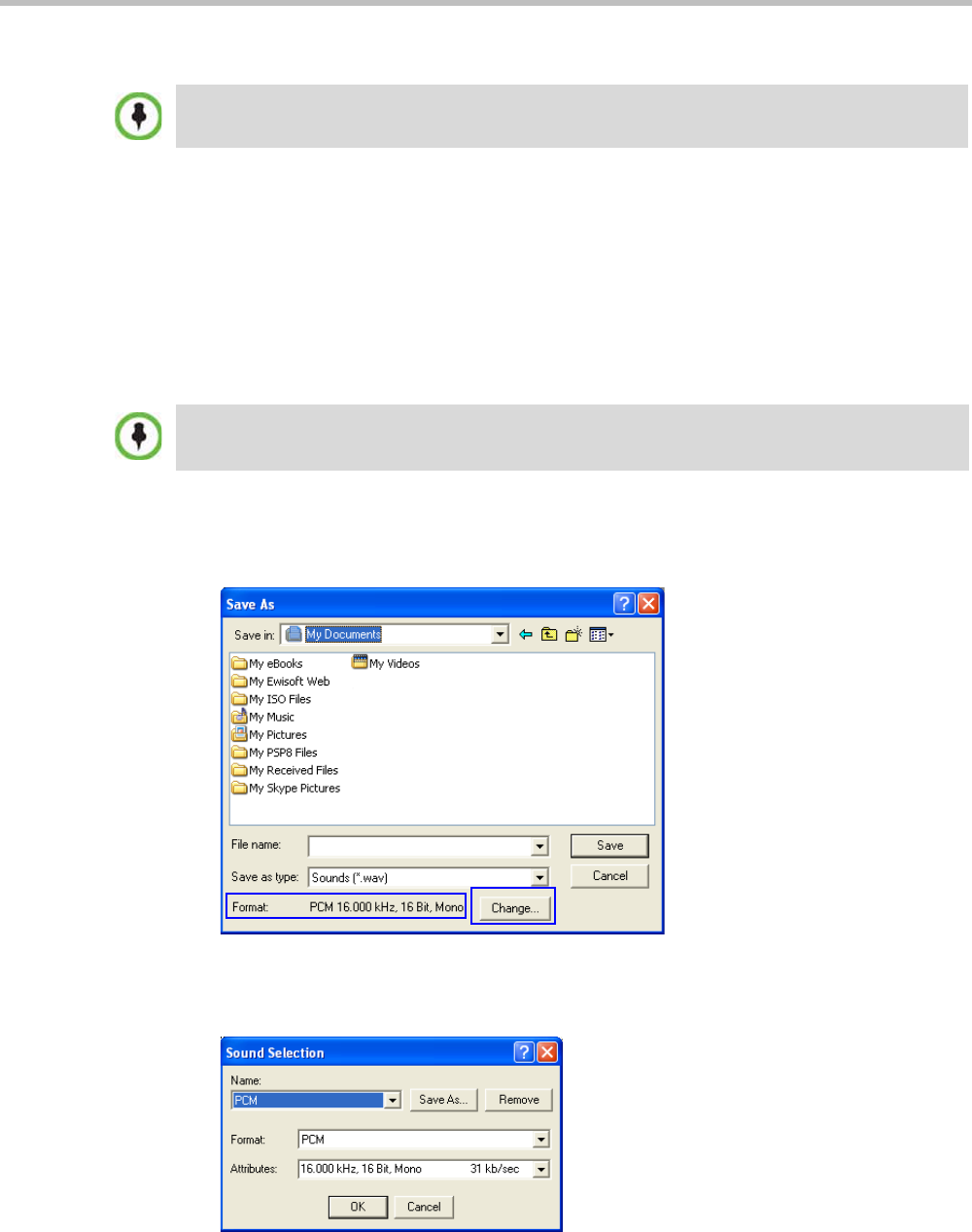
Chapter 16-IVR Services
Polycom, Inc. 16-29
To record a new audio message:
Make sure that a microphone or a sound input device is connected to
your PC.
1On your PC, click Start > Programs > Accessories > Entertainment > Sound Recorder.
The Sound–Sound Recorder dialog box opens.
2Click File > New.
3Click the Record button.
The system starts recording.
4Start narrating the desired message.
5Click the Stop Recording button.
6Save the recorded message as a wave file, click File > Save As.
The Save As dialog box opens.
7Verify that the Format reads: PCM 16.000 kHz, 16Bit, Mono. If the format is correct,
continue with step 10. If the format is incorrect, click the Change button.
The Sound Selection dialog box is displayed.
8In the Name field, select the name of the format created in step 7 on page 16-28.
Regardless of the recording utility you are using, verify that any new audio message recorded
adheres to the following format settings: 16.000kHz, 16Bit, Mono.
For all audio IVR messages, stop the recording anytime up to 3 minutes (which is the maximum
duration allowed for an IVR voice message). If the message exceeds 3 minutes it will be rejected by
the Collaboration Server unit.

Polycom® RealPresence Collaboration ServerVirtual Edition Administrator’s Guide
16-30 Polycom, Inc.
9Click OK.
The system returns to the Save As dialog box.
10 In the Save in field, select the directory where the file will be stored.
11 In the Save as Type field, select the *.wav file format.
12 In the File name box, type a name for the message file, and then click the Save button.
13 To record additional messages, repeat steps 1 to 10.
Creating a Welcome Video Slide
The video slide is a still picture that can be created in any graphic application.
To create a welcome video slide:
1Using any graphic application, save your image in either *.jpg or *.bmp file format.
2For optimum quality, ensure that the image dimensions adhere to the Collaboration
Server recommended values (width x height in pixels):
—640 x 480
—704 x 480
—848 x 480
—720 x 576
—704 x 576
—1024 x 576
—960 x 720
—1280 x 720
—1440 x 1088
—1920 x 1088
The Collaboration Server can accommodate small deviations from the recommended
slide resolutions.
3Save your file.
To upload your recorded *.wav file to the Collaboration Server, see step 6 on page 16-8.
Customized H.261 slides are not supported..
If using a default Polycom slide, the slide’s resolution will be as defined in the profile, i.e. SD, HD or
CIF.
If the display of the Welcome slide is cut in the upper area of the screen, change the settings of the
endpoint’s monitor to People "Stretch" instead of "Zoom".
To upload your video slide to the Collaboration Server, see step 12 on page 16-22.

Chapter 16-IVR Services
Polycom, Inc. 16-31
Default IVR Prompts and Messages
The system is shipped with the following audio prompts and messages:
Table 16-12 Default IVR Messages
Message Type Message Text When Played File Name
General Welcome
Message
“Welcome to unified conferencing.” The participant
enters the
conference IVR
queue
General_Welcome.wav
Chairperson
Identifier Request
“For conference Chairperson Services,
Press the Pound Key. All other
participants please wait...”
The participant is
asked to self-
identify as the
chairperson
Chairperson_ Identifier.wav
Request
Chairperson
Password
“Please enter the Conference
Chairperson Password. Press the
pound key when complete.”
The participant is
asked for the
chairperson
password
Chairperson_Password.wav
Retry Chairperson
Password
“Invalid chairperson password. Please
try again.”
A participant
enters an incorrect
Chairperson
password
Chairperson_
Password_Failure.wav
Request
Password
“Please enter the conference password.
Press the pound key when complete.”
A participant is
requested to enter
the conference
password
Conference_ Password.wav
Retry Password “Invalid conference password. Please
try again.”
An incorrect
conference
password is
entered
Retry_ Conference_
Password.wav
Request Digit “Press any key to enter the conference.” A participant is
requested to press
any key
Request_Digit.wav
Request Billing
Code
“Please enter the Billing code. Press the
pound key when complete.”
A participant is
asked to enter a
billing code
Billing_Code.wav
Requires
Chairperson
“Please wait for the chairperson to join
the conference.”
A participant
attempts to join a
conference prior to
the Chairperson
joining
Requires Chairperson.wav
Chairperson Exit “The chairperson has left the
conference.”
Note: The
TERMINATE_CONF_AFTER_CHAIR_
DROPPED flag must be enabled to play
this message.
The chairperson
has left the
conference.
Chairperson_Exit.wav

Polycom® RealPresence Collaboration ServerVirtual Edition Administrator’s Guide
16-32 Polycom, Inc.
First to Join “You are the first person to join the
conference.”
The first participant
joins a conference
First to Join.wav
Mute All On “All conference participants are now
muted.”
When all
participants are
muted by the
operator or
chairperson.
Mute_All_On.wav
Mute All Off “All conference participants are now
unmuted.”
When all
participants are
unmuted by the
operator or
chairperson.
Mute_All_Off.wav
End Time Alert “The conference is about to end.” The conference is
about it end
End_Time_Alert.wav
Change Password
Menu
“Press one to change conference
password.
Press two to change chairperson
password.
Press nine to exit the menu.”
A participant
requests a
conference
password change
Change_Password_ Menu.wav
Change
Conference
Password
“Please enter the new conference
password. Press the pound key when
complete.”
A participant
presses two in the
Change Password
IVR menu.
Change_ Conference_
Password.wav
Change
Chairperson
Password
“Please enter the new chairperson
password. Press the pound key when
complete.”
A participant
presses one in the
Change Password
IVR menu.
Change_ Chairperson_
Password.wav
Confirm Password
Change
“Please re-enter the new password.
Press the pound key when complete.”
A participant
enters a new
conference or
chairperson
password
Confirm_ Password_ Change.wav
Change Password
Failure
“The new password is invalid.” A participant
enters an invalid
password
Change_ Password_
Failure.wav
Password
Changed
Successfully
“The password has been successfully
changed.”
A participant has
confirmed a
password change
Password_ Changed_
Successfully.wav
Self Mute “You are now muted.” A participant mutes
his or her audio
Self_Mute.wav
Self Unmute “You are no longer muted.” A participant
unmutes his or her
audio
Self_Unmute.wav
Table 16-12 Default IVR Messages (Continued)
Message Type Message Text When Played File Name

Chapter 16-IVR Services
Polycom, Inc. 16-33
Chairperson Help
Menu
“The available touch-tone keypad
actions are as follows:
•To exit this menu press any key.
•To request private assistance, press
star, zero.
•To request operator’s assistance for
the conference, press zero, zero.
•To mute your line, press star, six.
•To unmute your line, press pound,
six.”
A chairperson
requests the
chairperson help
menu
Chairperson_ Help_Menu.wav
Participant Help
Menu
“The available touch-tone keypad
actions are as follows:
•To exit this menu press any key.
•To request private assistance, press
star, zero.
•To mute your line, press star, six.
•To unmute your line, press pound,
six.
•To increase your volume, press star,
nine.
•To decrease your volume, press
pound, nine.
A participant
requests the
participant help
menu
Participant_Help_Menu.wav
Maximum
Participants
Exceeded
“The conference is full. You cannot join
at this time.”
A participant
attempts to join a
full conference
Maximum_ Participants_
Exceeded.wav
Request
Conference
NID
“Please enter your conference NID.
Press the pound key when complete.”
Request_ Conference_NID.wav
Retry Conference
NID
“Invalid conference NID. Please try
again.”
A participant
enters an invalid
conference NID
Retry_Conference_NID.wav
Secured
Conference
“The conference is now secured.” A chairperson or
participant secures
a conference
Conference_Secured.wav
Unsecured
Conference
“The conference is now in an unsecured
mode”
A chairperson or
participant
unsecures a
conference
Conference_Unsecured.wav
Locked
Conference
“Conference you are trying to join is
locked”
Conference_Locked.wav
Conference
Recording
“The conference is being recorded” Recording_ in_Progress.wav
Table 16-12 Default IVR Messages (Continued)
Message Type Message Text When Played File Name

Polycom® RealPresence Collaboration ServerVirtual Edition Administrator’s Guide
16-34 Polycom, Inc.
Conference
Recording Failed
“The conference recording has failed” Recording_Failed.wav
No Video
Resources Audio
Only.
"All video resources are currently in
use. Connecting using audio only"
No_Video_Resources_Audio_
Only.wav
Table 16-12 Default IVR Messages (Continued)
Message Type Message Text When Played File Name

Polycom, Inc. 17-1
17
The Call Detail Record (CDR) Utility
The Call Detail Record (CDR) utility enables you to view summary information about
conferences, and retrieve full conference information and archive it to a file. The file can be
used to produce reports or can be exported to external billing programs.
The Collaboration Server can store details of up to 2000 conferences. When this number is
exceeded, the system overwrites conferences, starting with the earliest conference. To save
the conferences’ information, their data must be retrieved and archived. The frequency with
which the archiving should be performed depends on the volume of conferences run by the
MCU.
The Collaboration Server displays Active Alarms before overwriting the older files, enabling
the users to backup the older files before they are deleted.
The display of Active Alarms is controlled by the
ENABLE_CYCLIC_FILE_SYSTEM_ALARMS System Flag.
If the ENABLE_CYCLIC_FILE_SYSTEM_ALARMS is set to YES (default setting when
ULTRA_SECURE_MODE System Flag is set to YES) and a Cyclic File reaches a file storage
capacity limit, an Active Alarm is created: “Backup of CDR files is required”.
Each conference is a separate record in the MCU memory. Each conference is archived as a
separate file. Each conference CDR file contains general information about the conference,
such as the conference name, ID, start time and duration, as well as information about
events occurring during the conference, such as adding a new participant, disconnecting a
participant or extending the length of the conference.
The CDR File
CDR File Formats
The conference CDR records can be retrieved and archived in the following two formats:
•Unformatted data – Unformatted CDR files contain multiple records in “raw data”
format. The first record in each file contains general conference data. The remaining
records contain event data, one record for each event. Each record contains field values
separated by commas. This data can be transferred to an external program such as
Microsoft Excel for billing purposes.
The value of the fields that support Unicode values, such as the info fields, will be stored in the CDR
file in UTF8. The application that reads the CDR must support Unicode.
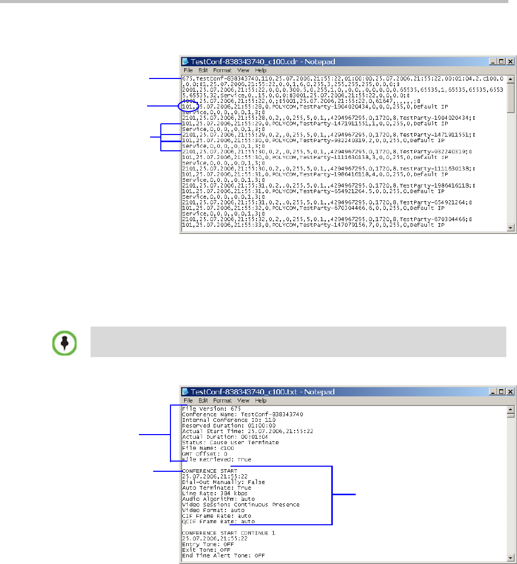
Polycom® RealPresence Collaboration ServerVirtual Edition Administrator’s Guide
17-2 Polycom, Inc.
The following is a sample of an unformatted CDR file:
Figure 17-1 Unformatted CDR File
•Formatted text – Formatted CDR files contain multiple sections. The first section in each
file contains general conference data. The remaining sections contain event data, one
section for each event. Each field value is displayed in a separate line, together with its
name. This data can be used to generate a summary report for a conference
The following is an example of a formatted CDR file:
Figure 17-2 Formatted CDR File
Conference
summary record
Event code
Event records
The field names and values in the formatted file will appear in the language being used for the
Collaboration Server Web Client user interface at the time when the CDR information is retrieved.
Event section
General conference
section
Event heading

Chapter 17-The Call Detail Record (CDR) Utility
Polycom, Inc. 17-3
Multi-Part CDR Files
By default, the maximum CDR (Call Data Record) file size is limited to 1MB. When a CDR
file reaches a size of 1MB the file is saved and further call data recording is stopped and the
additional data is lost.
The Collaboration Server can be configured to keep recording the data in multiple CDR file set
of 1MB each. Multi-Part CDR ensures that conference call data from long duration or
permanent conferences is recorded and not lost.
Guidelines
•Multi-Part CDR is enabled by setting the value of the ENABLE_MULTI_PART_CDR
System Flag to YES.
The flag’s default value is NO.
When the flag value is NO, CDR file size is limited to one file of 1MB and further call
data recording is stopped.
To modify the default setting, the flag must be manually added to the System
Configuration. For more information see, "Modifying System Flags” on page 20-1.
• If the flag value is set to YES, when a CDR file reaches 1MB, an additional CDR file is
created and added to the CDR file set for that conference.
•If the flag value is changed from YES to NO (or visa versa) all existing CDR files are
retained.
CDR File Contents
The general conference section or record contains information such as the Routing Name
and ID, and the conference starting date and time.
The event sections or records contain an event type heading or event type code, followed by
event data. For example, an event type may be that a participant connects to the conference,
and the event data will list the date and time the participant connects to the conference, the
participant name and ID, and the participant capabilities used to connect to the conference.
To enable compatibility for applications that written for the MGC family, the Collaboration
Server CDR file structure is based on the MGC CDR file structure.
The unformatted and formatted text files contain basically the same information. The
following differences should be noted between the contents of the unformatted and
formatted text files:
• In many cases a formatted text file field contains a textual value, whereas the equivalent
unformatted file field contains a numeric value that represents the textual value.
• For reading clarity, in a few instances, a single field in the unformatted file is converted
to multiple fields in the formatted text file, and in other cases, multiple fields in the
unformatted file are combined into one field in the formatted file.
• To enable compatibility between MGC CDR files and Collaboration Server CDR files, the
unformatted file contains fields that were applicable to the MGC MCUs, but are not
supported by the Collaboration Server MCUs. These fields are omitted from the
formatted text file.
Appendix C: "CDR Fields - Unformatted File” on page C-1, contains a full list of the events, fields
and values that appear in the unformatted file. This appendix can be referred to for information
regarding the contents of fields in the unformatted text file, but does not reflect the exact contents of
the formatted text file.
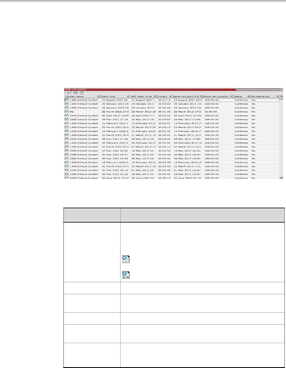
Polycom® RealPresence Collaboration ServerVirtual Edition Administrator’s Guide
17-4 Polycom, Inc.
Viewing, Retrieving and Archiving Conference Information
Viewing the Conference Records
To open the CDR utility:
•On the Collaboration Server Menu, click Administration > CDR.
The CDR List pane opens, displaying a list of the conference CDR records stored in the
MCU memory.
The following fields are displayed:
Table 17-1 Conference Record Fields
Field Description
Display Name The Display Name of the conference and an icon indicating whether or
not the CDR record has been retrieved and saved to a formatted text
file.
The following icons are used:
The CDR record has not been saved.
The CDR record has been saved.
Start Time The actual time the conference started.
GMT Start Time The actual time the conference started according to Greenwich Mean
Time (GMT).
Duration The actual conference duration.
Reserved Start Time The reserved start time of the conference. If the conference started
immediately this is the same as the Start Time.
Reserved Duration The time the conference was scheduled to last. Discrepancy between
the scheduled and the actual duration may indicate that the
conference duration was prolonged or shortened.
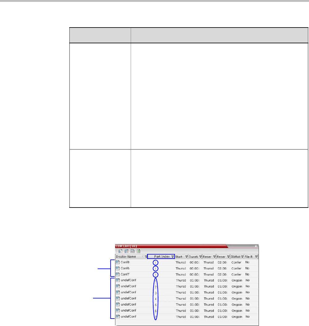
Chapter 17-The Call Detail Record (CDR) Utility
Polycom, Inc. 17-5
Multi-part CDR File display
When the Multi-Part CDR is configured on the Collaboration Server, an additional column,
Part Index, is added to the CDR list.
The Part Index column displays the CDR file’s sequence in the CDR file set:
•CDRs that are up to 1MB consist of a single file. Each file has a unique Display Name and
a Part Index of 1.
• Files included in a Multi-Part CDR file sets have the same Display Name. The first file of
the set is numbered 1 with each additional CDR file numbered in an ascending numeric
sequence.
Status The conference status. The following values may be displayed:
•Ongoing Conference
•Terminated by User
•Terminated when end time passed
•Automatically terminated when conference was empty – The
conference ended automatically because no participants joined the
conference for a predefined time period, or all the participants
disconnected from the conference and the conference was empty
for a predefined time period.
•Conference never became ongoing due to a problem
•Unknown error
Note: If the conference was terminated by an MCU reset, the status
Ongoing Conference will be displayed.
File Retrieved Indicates if the conference record was downloaded using any of the
file retrieval buttons in the CDR List pane or the API.
•Yes - when the conference record was retrieved to any file or using
the API.
•No - when the conference record was not retrieved at all.
The File Retrieved field is updated whenever the record is
downloaded.
Table 17-1 Conference Record Fields (Continued)
Field Description
Single FIle CDRs
Multi-Part CDR
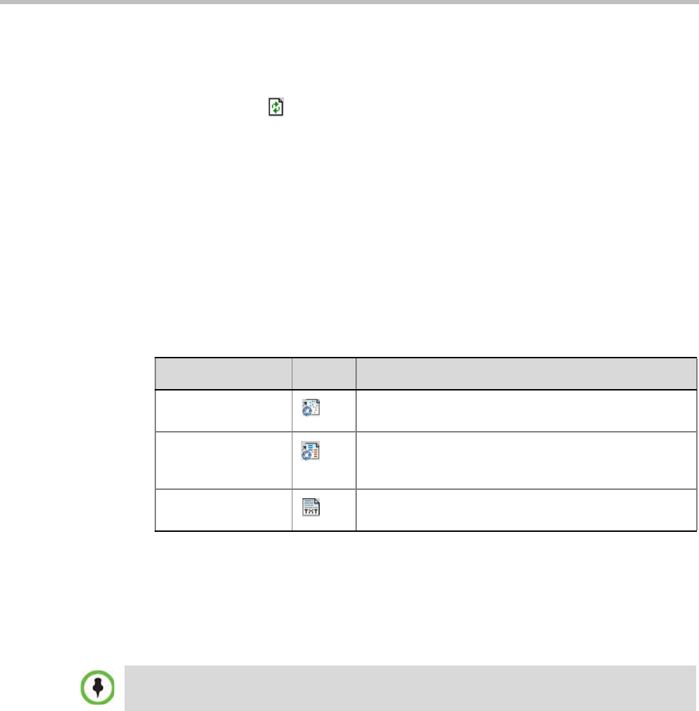
Polycom® RealPresence Collaboration ServerVirtual Edition Administrator’s Guide
17-6 Polycom, Inc.
Refreshing the CDR List
To refresh the CDR list:
•Click the Refresh button, or right-click on any record and then select Refresh.
Updated conference CDR records are retrieved from the MCU memory.
Retrieving and Archiving Conference CDR Records
To retrieve and archive CDR records:
1To retrieve a single CDR record, right-click the record to retrieve and then select the
required format (as detailed in Table 17-2).
Alternatively, select the record to retrieve, and then click the appropriate button on the
toolbar (as detailed in Table 17-2).
To retrieve multiple CDR records simultaneously, use standard Windows multi-
selection methods.
The Retrieve dialog box opens.
The dialog box displays the names of the destination CDR files.
2Select the destination folder for the CDR files and then click OK.
If the destination file already exists, you will be asked if you want to overwrite the file
or specify a new name for the destination file.
The files are saved to the selected folder.
Table 17-2 Conference Information Retrieval Options
Menu Option Button Action
Retrieve Retrieves the conference information as unformatted data
into a file whose extension is .cdr.
Retrieve Formatted
XML
Retrieves the conference information as formatted text
into a file whose extension is .xml.
Note: Viewed when logged in as a special support user.
Retrieve Formatted Retrieves the conference information as formatted text
into a file whose extension is .txt.
CDR files are not included in the backup process and should be backed up manually by saving the
CDR files to a destination device.

Polycom, Inc. 18-1
18
RMX Manager Application
The RMX Manager is the Windows version of the Collaboration Server Web Client. It can be
used instead of the Collaboration Server Web Client for routine Collaboration Server
management and for Collaboration Server management.
Using the RMX Manager application, a single user can control a single or multiple MCU
units as well as conferences from multiple MCUs. The RealPresence Collaboration Server
Virtual Edition system can be managed and controlled by the RMX Manager application.
The RMX Manager can list and monitor:
• Up to 20 Collaboration Server systems in the MCUs pane
• Up to 800 conferences in the Conferences pane
• Up to 1600 participants in the Participants pane
The RMX Manager is faster than the RMX Web Client and can give added efficiency to
Collaboration Server management tasks, especially when deployed on workstations affected
by:
• Lack of performance due to bandwidth constraints within the LAN/WAN
environment.
• Slow operation and disconnections that can be caused by the anti-phishing component
of various antivirus applications.
The RMX Manager application can be installed in your local workstation or accessed directly
on the RealPresence Collaboration Server system without installing it in your workstation.
Accessing the RMX Manager Directly
To access the RMX Manager directly:
>> Start Internet Explorer and in your browser enter:
http://<Collaboration Server IP Address>:8080/RMXManager.html.
For example, if the Collaboration Server IP address is 10.226.10.46, enter in the browser
the following address: http://10.226.10.46:8080/RMXManager.html.
Users with Auditor authorization level cannot connect to the RealPresence Collaboration Server via
the RMX Manager application and must use the RMX Web Client.
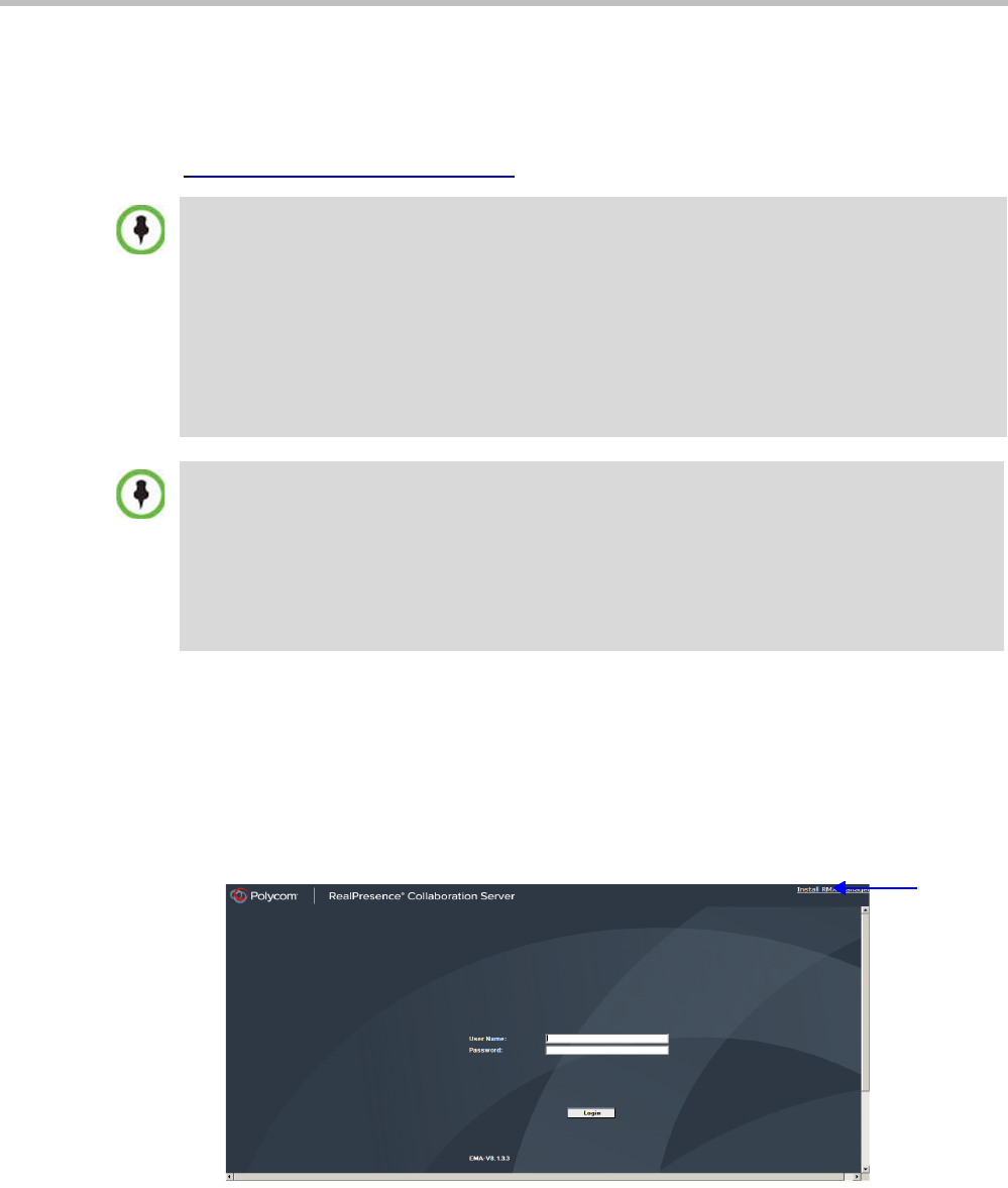
Polycom® RealPresence Collaboration ServerVirtual Edition Administrator’s Guide
18-2 Polycom, Inc.
Installing the RMX Manager
The RMX Manager application can be downloaded from one of the RealPresence Collaboration
Server systems installed in your site or from Polycom web site at
http://www.polycom.com/support.
To install RMX Manager (downloading the application from the RealPresence
Collaboration Server):
1Start Internet Explorer and connect to one of the Collaboration Server units in your site. It
is recommended to connect to the Collaboration Server installed with the latest software
version.
The Login screen is displayed. There is a link to the RMX Manager Installer at the top of
the right edge of the
screen.
2Click the Install RMX Manager link.
Upgrade Notes
•When upgrading the RMX Manager application, it is recommended to backup the MCU list using
the Export RMX Manager Configuration option. For more details, see "Import/Export RMX
Manager Configuration” on page 18-20.
•When upgrading the RMX Manager from a major version (for example, version 8.0) to a
maintenance version of that version (for example, 8.0.x), the installation must be performed from
the same MCU (IP address) from which the major version (for example, version 8.0) was
installed.
If you are upgrading from another MCU (different IP address), you must first uninstall the RMX
Manager application using Control Panel > Add or Remove Programs.
New RealPresence Collaboration Server Installation Note
When managing the RealPresence Collaboration Server, upgrade/install the latest MCU version and
then install the latest RMX Manager application.
The Collaboration Server Installation and First Entry Configuration must be completed before
installing the RMX Manager application. For more details, see the Polycom® RealPresence
Collaboration Server Virtual Edition Getting Started Guide, "Software Installation” on page 2-1.
Once the connection to the Collaboration Server unit is established and the Login window is
displayed, the RMX Manager application can be installed.
Link to
RMX
Manager
Installer
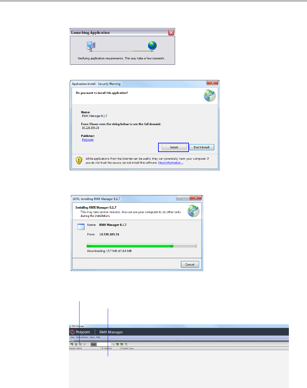
Chapter 18-RMX Manager Application
Polycom, Inc. 18-3
The installer verifies the application’s requirements on the workstation.
The Install dialog box is displayed.
3Click Install.
The installation proceeds.
The installation completes, the application loads and the RMX Manager - MCUs screen
is displayed.
The first time you start the RMX Manager application, the MCUs pane is empty.
MCUs Pane
MCUs Toolbar
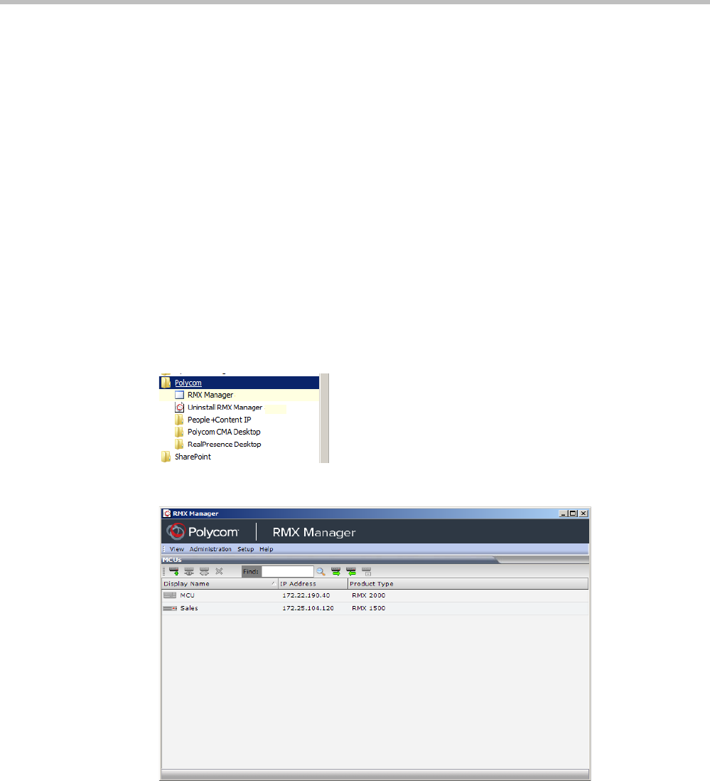
Polycom® RealPresence Collaboration ServerVirtual Edition Administrator’s Guide
18-4 Polycom, Inc.
Starting the RMX Manager Application
Once installed, the RMX Manager can be run using the http:// (non-secured) or https://
(secured) command in the browser’s address line or the Windows Start menu.
To use the browser:
1In the browser’s command line, enter:
http://<MCU Control Unit IP Address>:8080/RMXManager.html
or
https://<MCU Control Unit IP Address>:8080/RMXManager.html
2Press Enter.
To use the Windows Start menu:
1Click Start > Programs.
aIf the RMX Manager is displayed in the recently used programs list, click RMX
Manager in the list to start the application.
or
bClick All Programs > Polycom > RMX Manager.
The MCUs screen is displayed, listing the MCUs currently defined in the RMX Manager.
This screen enables you to add additional MCUs or connect to any of the MCUs listed.
For details on adding MCUs, see “Adding MCUs to the MCUs List” on page 11.
For each listed MCU, the system displays the following information:
—MCU Display Name (as defined in the Add MCU dialog box).
—IP Address of the MCU’s control unit
—Product Type - The MCU type: RealPresence Collaboration Server 800s, RMX
800VE, RealPresence Collaboration Server (RMX) 1500, RealPresence Collaboration
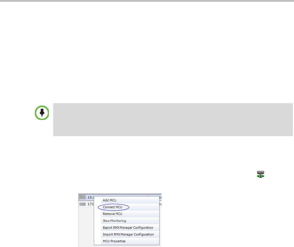
Chapter 18-RMX Manager Application
Polycom, Inc. 18-5
Server (RMX) 2000, or RealPresence Collaboration Server (RMX) 4000.
Before connecting to the MCU for the first time, the Collaboration Server type is
unknown so “RMX” is displayed instead as a general indication.
To display the RMX Manager main screen you must connect to one of the listed
Collaboration Servers. For more details, see "Connecting to the MCU” on page 18-5.
Connecting to the MCU
Once an MCU is defined, the RMX Manager can be connected to it. This allows you to set up
conferences, make reservations, monitor On Going Conferences and perform other activities
on several MCUs.
To connect the RMX Manager to an MCU:
1In the MCUs pane or screen, use one of the following methods:
aDouble-click the MCU icon.
bSelect the Collaboration Server to connect and click the Connect MCU button.
cRight-click the MCU icon and then click Connect MCU.
The first Collaboration Server unit that is connected to the RMX Manager dictates the Authorization
Level of Users that can connect to the other MCUs on the list. For example, if the Authorization level
of the User POLYCOM is Administrator, all Users connecting to the other MCUs on the list must be
Administrators. Each user can have a different login name and password for each of the listed
MCUs and they must be defined in the Users list of each of the listed MCUs.
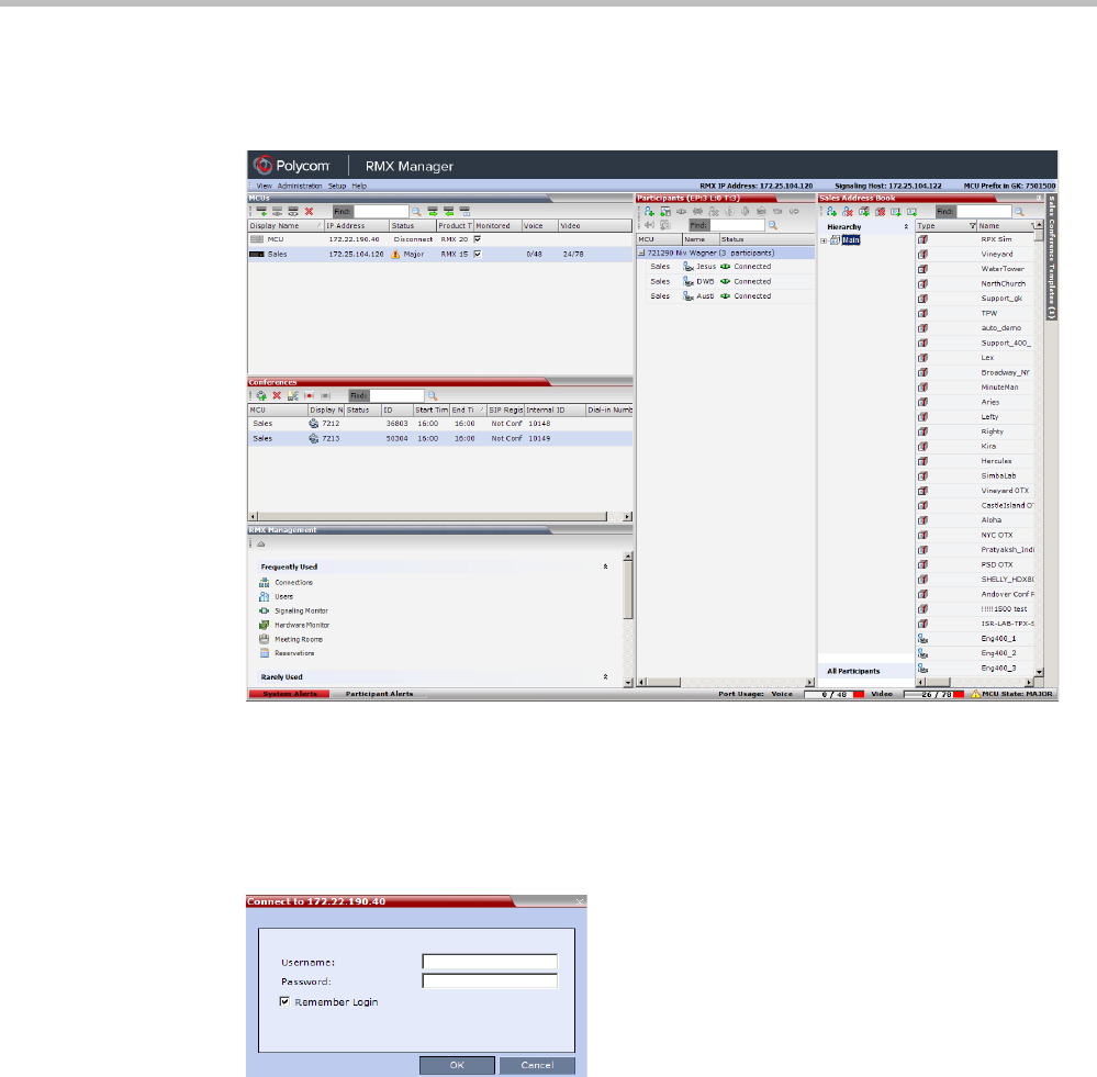
Polycom® RealPresence Collaboration ServerVirtual Edition Administrator’s Guide
18-6 Polycom, Inc.
If you are connecting to the MCU from the MCUs opening screen and have defined the
Username and Password for the connecting MCU, the system connects to the Collaboration
Server, and the RMX Manager Main Screen is displayed.
If you are connecting to any MCU from the MCUs pane in the RMX Manager Main
Screen and have defined the Username and Password for the connecting MCU, the MCU
icon changes to connected and its status, type and number of audio and video resources
are displayed in the MCUs pane.
If the Username and Password are missing from the MCU parameters, or if the Remember
Me check box has been cleared, the Connect dialog box opens.
2In the Username field, enter the user name with which you will login to the MCU.
3In the Password field, enter the password as defined for the user name with which you
will login to the MCU.
4To add the user name and password to the MCU properties so you will not have to
enter them each time you login to the MCU, make sure that the Remember Login check
box is selected. Otherwise, clear the Remember Login check box.
5Click OK.
The system connects to the Collaboration Server, and the RMX Manager Main Screen is
displayed.
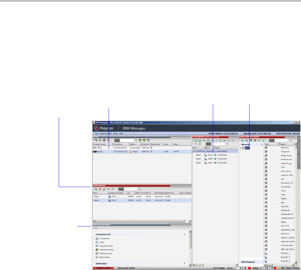
Chapter 18-RMX Manager Application
Polycom, Inc. 18-7
If a User with the entered Username and Password is not defined in the Collaboration
Server, an error message is displayed and the system lets you re-enter the Username and
Password.
RMX Manager Main Screen
The RMX Manager Main Screen is displayed only when at least one MCU is connected.
This screen is similar to the RMX Web Client Main Screen with the addition of the MCUs
pane. As in the RMX Web Client, the panes are displayed according to the Authorization Level
of the logged in User. The MCUs pane is displayed to all users.
Only one MCU can be selected in the MCUs pane. If only one MCU is connected, it is
automatically selected. The selected MCU is highlighted.
The menu items, the Collaboration Server Management features, the Address Book and the
Conference Templates are all properties of the selected MCU and apply to it.
MCUs Pane
The selected MCU is highlighted
Ongoing
Conferences
Pane
Device
Management
Pane
List Pane Address Book Pane
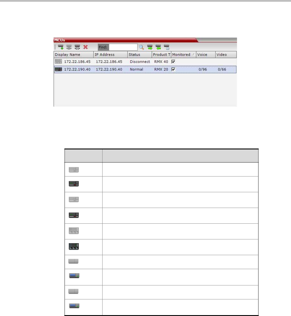
Polycom® RealPresence Collaboration ServerVirtual Edition Administrator’s Guide
18-8 Polycom, Inc.
MCUs Pane
The MCUs pane includes a list of MCUs and a toolbar.
For each listed MCU, the system displays the following information:
•MCU Display Name - the name of the MCU and its icon according to its type and
connection status. The following icons are available:
•IP Address of the MCU’s control unit.
•Status - The status of the MCU:
—Connected - the MCU is connected to the RMX Manager and can be managed by the
RMX Manager user.
—Disconnected - The MCU is disconnected from the RMX Manager
—Major - The MCU has a major problem. MCU behavior could be affected and
attention is required.
Table 18-1 MCU Icons and Statuses
Icon Description
RealPresence Collaboration Server (RMX) 1500, disconnected.
RealPresence Collaboration Server (RMX) 1500, connected.
RealPresence Collaboration Server (RMX) 2000, disconnected.
RealPresence Collaboration Server (RMX) 2000, connected.
RealPresence Collaboration Server (RMX) 4000, disconnected.
RealPresence Collaboration Server (RMX) 4000, connected.
RealPresence Collaboration Server 800s, disconnected
RealPresence Collaboration Server 800s, connected
RealPresence Collaboration Server Virtual Edition, disconnected
RealPresence Collaboration Server Virtual Edition, connected
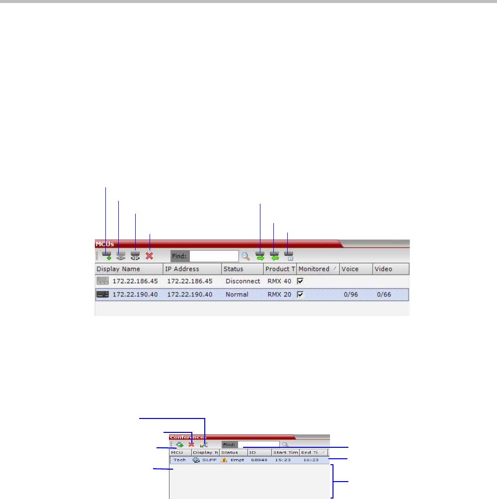
Chapter 18-RMX Manager Application
Polycom, Inc. 18-9
•Product Type - The MCU type: RealPresence Collaboration Server 1800, RealPresence
Collaboration Server 1500/2000/4000, RMX 800VE.
Before connecting to the MCU for the first time, the Collaboration Server type is
unknown so RMX is displayed instead as a general indication.
•Monitored - When checked indicates that the conferences running on this MCU are
automatically added to the Conferences list and monitored. To stop monitoring the
conferences running on this MCU and their participants, clear the Monitored check box.
•Video Resources - The number of video resources that are available for conferencing.
•Audio Resources - The number of audio resources that are available for conferencing.
MCUs Toolbar
The MCUs toolbar contains the following buttons:
Conferences Pane
The Conferences pane lists all the ongoing conferences from all the MCUs that are connected
and monitored along with their MCU, Status, Conference ID, Start Time and End Time data.
The number of ongoing conferences is displayed in the pane’s title.
The Conferences list toolbar contains the following buttons:
Monitoring conferences
New conferences run on MCUs selected for Monitoring are automatically added to the
Conferences list. You can sort the conferences by MCU by clicking the MCU column heading
in the Conferences table. Conferences run on MCUs that are connected but not monitored are
not listed.
Using Windows multiple selection methods to select conferences, participants from several
conferences running on different MCUs can be listed in the Participants list pane.
Starting a new conference
When starting a new conference, you must first select the MCU to run the conference in the
MCUs pane.
Add MCU
Connect MCU
Disconnect MCU
Delete MCU MCU Properties
Import Configuration
Export Configuration
Toolbar
List Headers
Conference Data
New Conference
Delete Conference
Save Conference
to Template
MCU Name
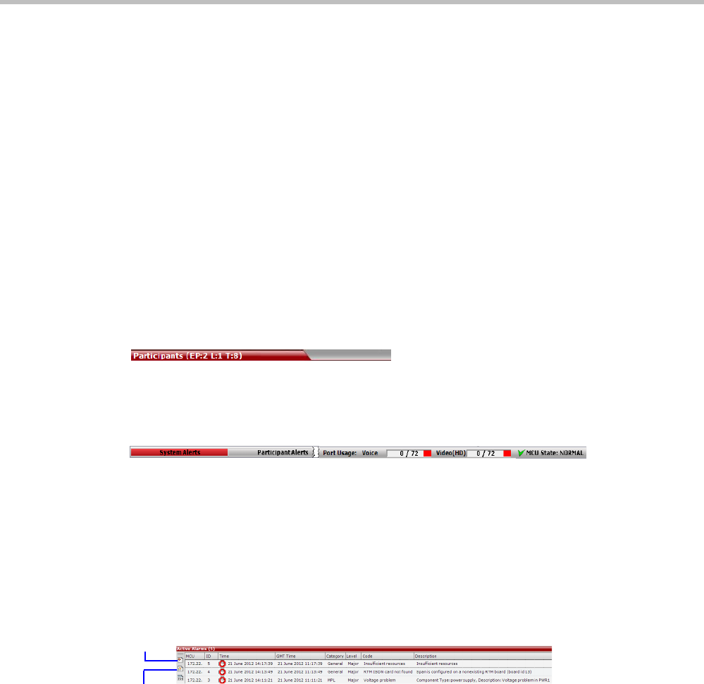
Polycom® RealPresence Collaboration ServerVirtual Edition Administrator’s Guide
18-10 Polycom, Inc.
Collaboration Server Management
The Collaboration Server Management pane lists the entities of the selected MCU that need to
be configured to enable the Collaboration Server to run conferences. Only users with
Administrators permission can modify these parameters.
The Collaboration Server Management pane is divided into two sections:
•Frequently Used – parameters often configured monitored or modified.
•Rarely Used – parameters configured during initial system set-up and rarely modified
afterward.
List Pane
The List pane displays details of the participants connected to the conferences selected in the
Conferences pane or the item selected in Collaboration Server Management pane. The title of the
pane changes according to the selected item.
When selecting an item in the Collaboration Server Management pane it applies only to the
MCU selected in the MCUs list. In such a case, the system displays the name of the selected
MCU in the List pane title.
Status Bar
The Status Bar at the bottom of the RMX Web Client contains System and Participant Alerts
tabs as well as Port Usage Gauges and an MCU State indicator.
System Alerts
Lists system problems of all connected MCUs (even if the MCU is not monitored). The alert
indicator flashes red when at least one system alert is active. The flashing continues until a
user with Operator or Administrator permission reviews the list.
The System Alerts can be sorted by MCU by clicking the MCU header in the System Alerts
table.
The System Alerts pane is opened and closed by clicking the System Alerts button in the left
corner of the Status Bar.
For more information about Active Alarms and Faults List, see "System and Participant
Alerts” on page 19-1.
Participant Alerts
Lists the participants of all monitored MCUs that are experiencing connection problems.
The list is sorted by MCU and conference.
The Participant Alerts can be sorted by MCU by clicking the MCU header in the Participant
Alerts table.
Active
Alarms
Faults
List
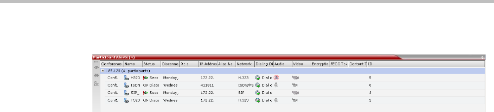
Chapter 18-RMX Manager Application
Polycom, Inc. 18-11
The Participant Alerts pane is opened and closed by clicking the Participant Alerts button in
the left corner of the Status Bar.
Port Usage Gauges
The Port Usage gauges display for the selected MCU:
• The total number of Video ports in the system according.
• The number of Video ports in use.
•The High Port Usage threshold.
For more details, see the Polycom® RealPresence Collaboration Server Virtual Edition Getting
Started Guide, "Port Usage Gauges” on page 3-7.
MCU State
The MCU State indicator displays the status of the selected MCU.
For more details, see the Polycom® RealPresence Collaboration Server Virtual Edition Getting
Started Guide, "MCU State” on page 3-7.
Address Book
Displays the Address Book of the selected MCU (regardless of its Monitored status). The
Address Book is a list of Participants and Groups that have been defined on the selected
Collaboration Server.
The information in the Address Book can be modified only by an administrator. All
Collaboration Server users can, however, view and use the Address Book to assign participants
to conferences.
The name of the selected Collaboration Server is displayed in the title of the Address Book
pane. For more details, see the Polycom® RealPresence Collaboration Server Virtual Edition
Getting Started Guide, "Address Book” on page 3-8.
Conference Templates
Conference Templates enable administrators and operators to create, save, schedule and
activate identical conferences.
The Conference Templates pane lists the Conference Templates that have been defined on the
selected Collaboration Server (regardless of its Monitored status).
The Conference Templates pane is initially displayed as a closed tab. The name of the selected
Collaboration Server and the number of saved Conference Templates is indicated on the tab.
For more details, see the Polycom® RealPresence Collaboration Server Virtual Edition Getting
Started Guide, "Conference Templates” on page 3-9.
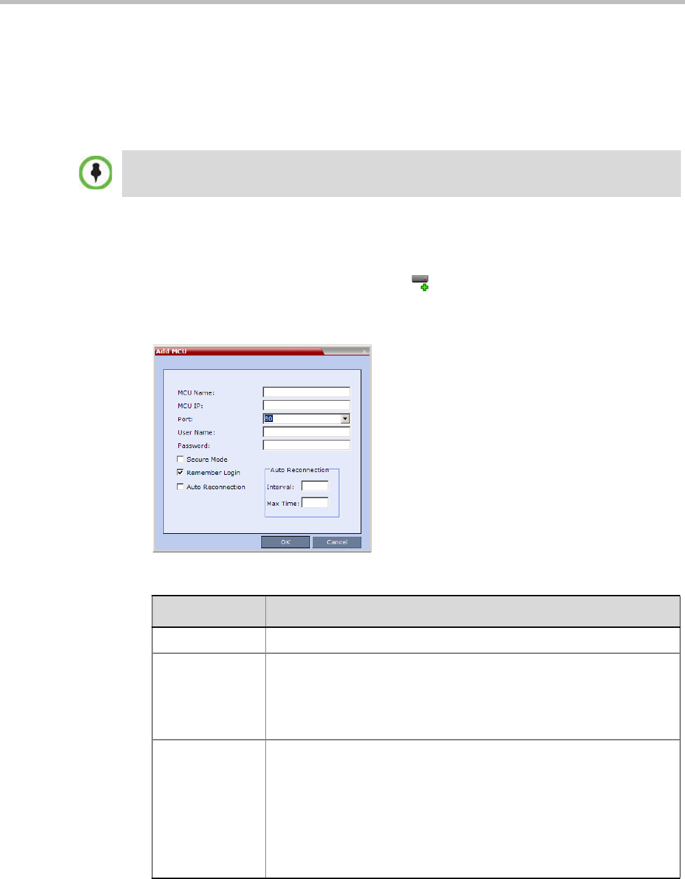
Polycom® RealPresence Collaboration ServerVirtual Edition Administrator’s Guide
18-12 Polycom, Inc.
Adding MCUs to the MCUs List
The RMX Manager can connect to one or several Collaboration Servers simultaneously. If the
site’s configuration includes more than one MCU, or when a new MCU is added to your
configuration, and you want to monitor and control all MCUs from within the same
window, you must add the MCU to the MCUs list.
To add the MCU to the list of MCUs being managed, define the MCU’s connection
parameters.
To add a Collaboration Server unit:
1On the MCUs toolbar, click the Add MCU button to add an MCU to the MCU list.
The Add MCU dialog box opens.
2Define the following parameters:
The Collaboration Server must be installed and its IP addresses properly configured in the
Management Network Service before defining its connection parameters in the RMX Manager
application.
Table 19 MCU Properties
Field Description
MCU Name Enter the name of the MCU on the network.
MCU IP Enter the IP address of the MCU’s Control Unit. The IP address must be
identical to the one configured in the MCU during first entry Configuration.
For more details, see the Polycom® RealPresence Collaboration Server
Virtual Edition Getting Started Guide, "To obtain the IP address of the
Virtual Machine:” on page 2-21.
Port Enter the number of the port used for communication and data
transactions between the Collaboration Server unit and the RMX
Manager.
For standard connection, enter 8080.
For a Secured connection (using TLS or SSL), enter 4433.
Note: When using the RMX Manager with other Collaboration Server
models, the standard connection port is 80 and the secured connection
port is 443.
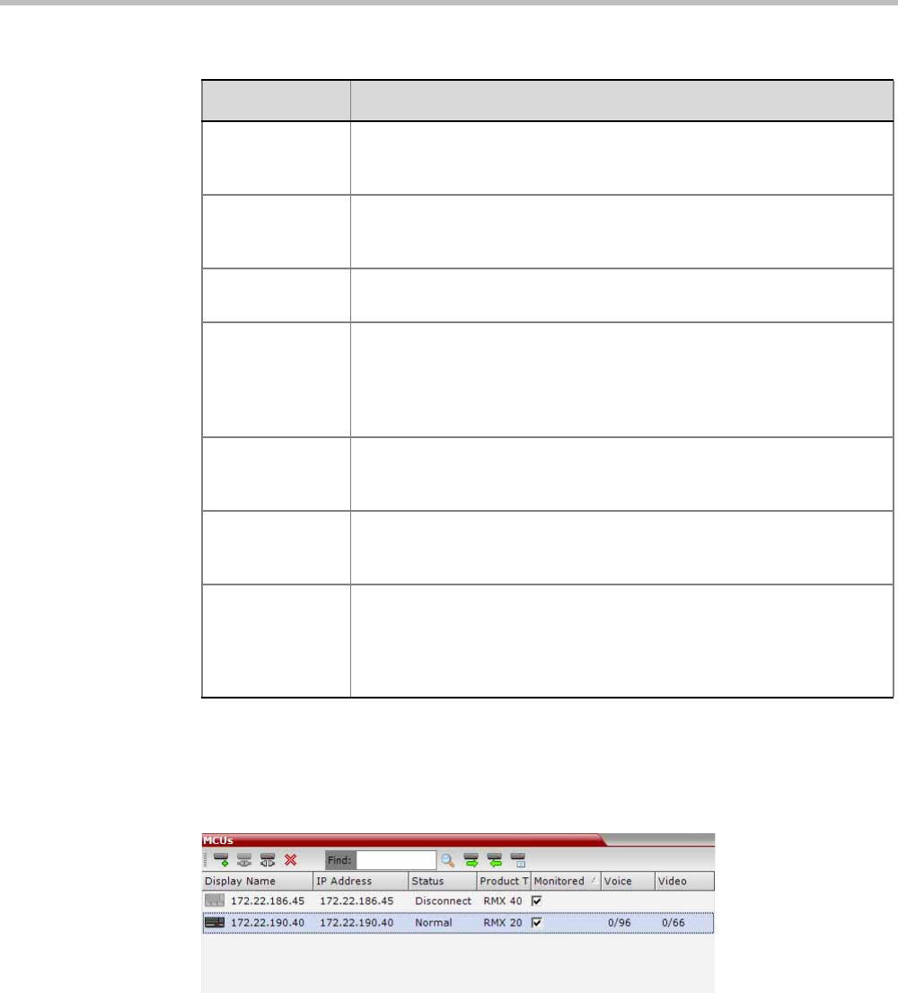
Chapter 18-RMX Manager Application
Polycom, Inc. 18-13
3Click OK.
The MCU is added to the MCUs pane.
4If required, repeat steps 1-3 to define additional Collaboration Server units.
The MCUs pane contains the list of all defined MCUs.
Starting a Conference
There are several ways to start a conference:
• Clicking the New Conference button in the Conferences pane. For more information, see
“Starting a Conference from the Conferences Pane” on page 13.
Username Enter the user name with which you will login to the MCU. A User with
this name must be defined in the Collaboration Server Users list. The
system is shipped with a default User whose name is POLYCOM.
Password Enter the password as defined for the user name with which you will login
to the MCU. The system is shipped with a default User whose password
is POLYCOM.
Secure Mode Optional. Select this check box to connect to the Collaboration Server
with SSL and work in Secure Mode.
Remember Login This check box is automatically selected, and it enables the usage of the
user name and password entered in this dialog box when connecting to
the Collaboration Server.
If this check box is cleared, the user is prompted for the user name and
password when connecting to this Collaboration Server unit.
Auto
Reconnection
Select this check box to automatically reconnect to the Collaboration
Server if the connection between the RMX Manager and the MCU is
broken.
Interval Enter time in seconds between reconnect ion attempts to the
Collaboration Server. For example, if you enter 10, the system will wait
10 seconds between the connection attempts.
Max Time Enter the maximum amount of time in seconds that the Collaboration
Server is allowed to try to reconnect. If the Collaboration Server
reconnects before the allotted time frame the count down timer is halted.
For example, if you enter 100, the system will stop trying to reconnect if it
has failed to do so within 100 seconds.
Table 19 MCU Properties (Continued)
Field Description
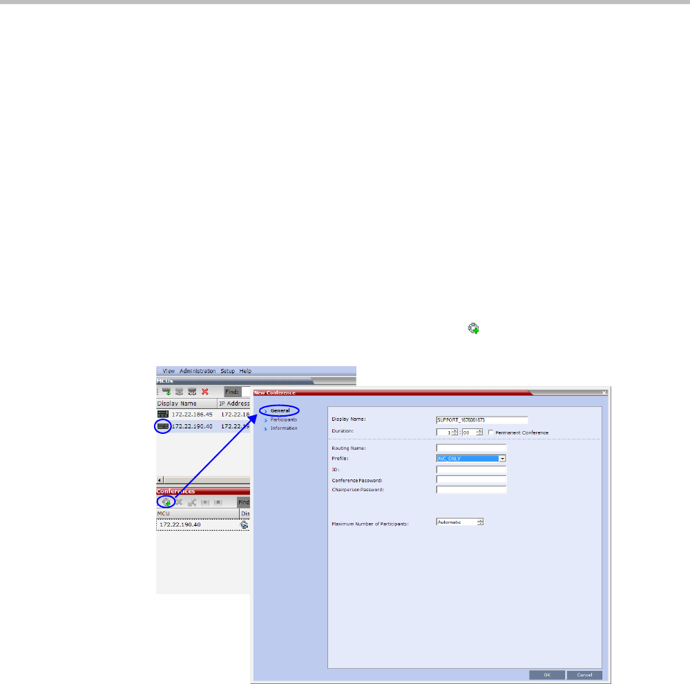
Polycom® RealPresence Collaboration ServerVirtual Edition Administrator’s Guide
18-14 Polycom, Inc.
• Dialing in to a Meeting Room defined on any of the MCUs.
—A Meeting Room is a conference that is saved on the MCU. It remains in passive
mode until it is activated by the first participant, or the meeting organizer dialing
in. For more information about Meeting Rooms, see "Meeting Rooms” on page 6-1.
• Dialing in to an Ad Hoc Entry Queue defined on one of the MCUs which is used as the
access point to the MCU.
For a detailed description of Ad Hoc Entry Queues, see "Entry Queues” on page 7-1.
•Start any Conference Template saved in the Conference Templates list.
For more information, see "Starting an Ongoing Conference From a Template” on
page 18-14.
Starting a Conference from the Conferences Pane
To start a conference from the Conference pane:
1In the MCUs pane, select the MCU to run the conference.
2In the Conferences pane, click the New Conference ( ) button.
The New Conference – General dialog box opens.
The system displays the conference’s default Name, Duration and the default Profile,
which contains the conference parameters and media settings.
The Collaboration Server automatically allocates the conference ID, when the conference
starts.
In most cases, the default conference ID can be used and you can just click OK to launch
the conference. If required, you can enter a conference ID before clicking OK to launch
the conference.
If you are the meeting chairperson or organizer using the RMX Web Client to start your
own meeting, you need to communicate the default conference ID (or the one you
created) to the other conference participants so they can dial in.
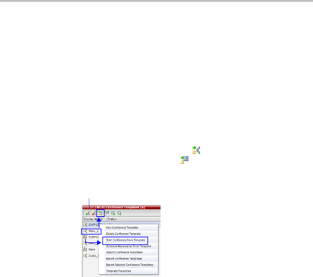
Chapter 18-RMX Manager Application
Polycom, Inc. 18-15
You can use the New Conference - General dialog box to modify the conference
parameters. If no defined participants are to be added to the conference, or you do not
want to add additional information, click OK.
For more details, see the Polycom® RealPresence Collaboration Server Virtual Edition
Getting Started Guide, "Starting an AVC CP Conference from the Conferences Pane” on
page 3-13.
Starting an Ongoing Conference From a Template
An ongoing conference can be started from any Conference Template saved in the
Conference Templates list of the selected MCU.
To start an ongoing conference from a Template:
1In the MCUs pane, select the MCU to run the conference.
1In the Conference Templates list, select the Template you want to start as an ongoing
conference.
2Click the Start Conference from Template () button to start a conference or
Schedule Reservation from Template ( ) button to schedule a reservation.
or
Right-click and select Start Conference from Template to start an ongoing conference
or Schedule Reservation from Template to schedule a reservation.
The conference is started.
For detailed description of Conference Templates, see "Using Conference Templates” on
page 10-2.
Monitoring Conferences
When MCUs are connected to the RMX Manager they are automatically monitored, that is,
any ongoing conference that is started on that MCU is automatically added to the
Conferences pane and its participants are monitored.
To list participants from several conferences (running on the same or different MCUs):
>> In the Conferences pane, using Windows multiple selection methods, select the
conferences whose participants you want to list.
The participants are displayed in the Participants list pane.
Name of selected MCU
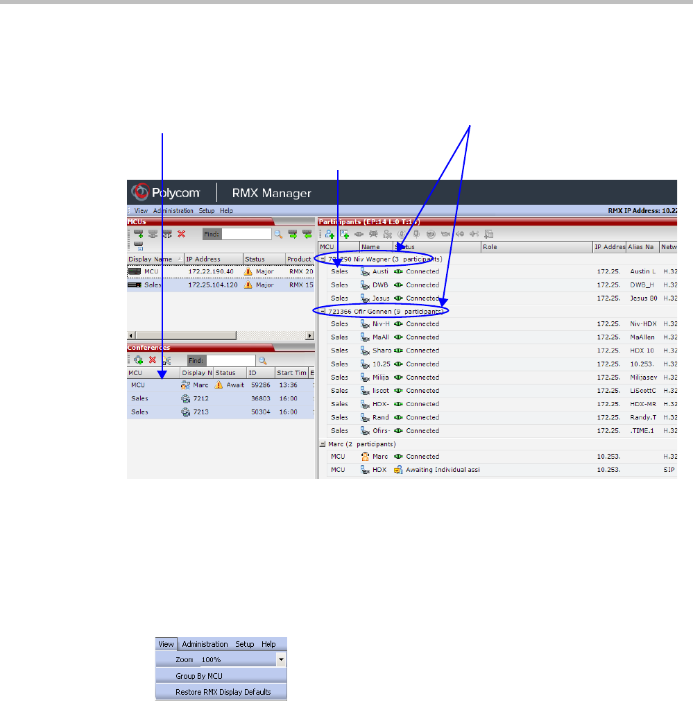
Polycom® RealPresence Collaboration ServerVirtual Edition Administrator’s Guide
18-16 Polycom, Inc.
By default, the participants are grouped by conferences, and the name of the MCU is
displayed in the first column of the properties table, enabling sorting according to MCU
name.
Grouping the Participants by MCU
The Participants can be grouped by MCU and then by conferences.
To change the display mode for the Participants pane:
>> On the Collaboration Server Menu, click View > Group by MCU.
Conferences selected for
monitoring
Group by Conference
MCU Name.
can be used for
sorting by clicking
on the column
heading
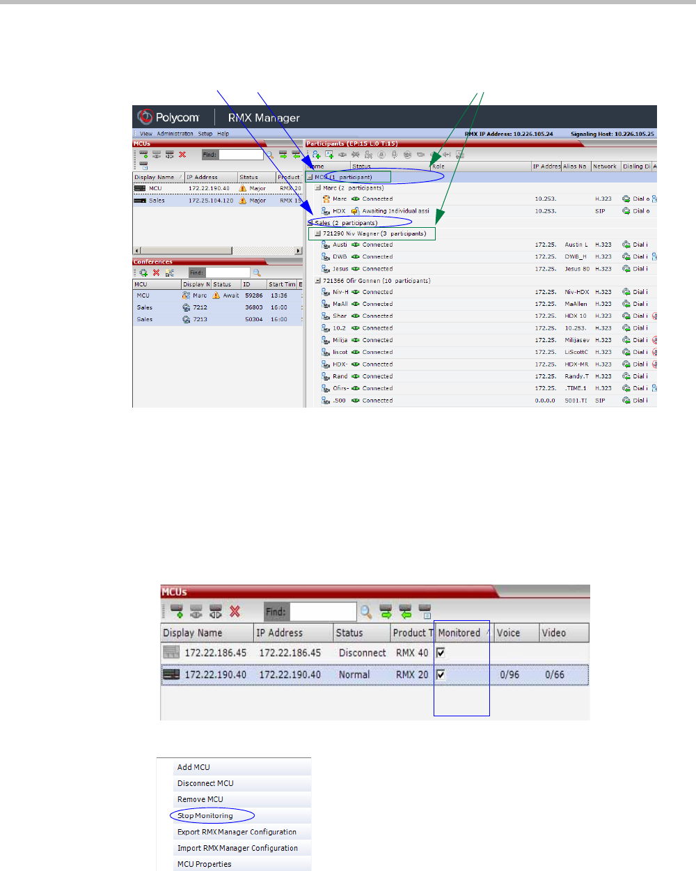
Chapter 18-RMX Manager Application
Polycom, Inc. 18-17
The Participants pane display changes accordingly.
To toggle between the two display modes, click View > Group by MCU.
Start Monitoring/Stop Monitoring
By default, all conferences running on connected Collaboration Servers are monitored.
You can stop the automatic monitoring of conferences on a specific MCU in one of the
following methods:
• By clearing the check box in the Monitored column in the MCUs pane.
• Right-clicking the MCU icon and selecting Stop Monitoring.
The check box is cleared in the Monitored column.
Group by Conference Group by MCU
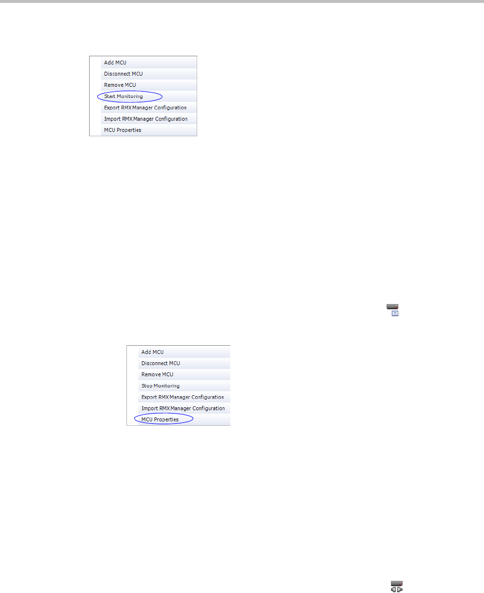
Polycom® RealPresence Collaboration ServerVirtual Edition Administrator’s Guide
18-18 Polycom, Inc.
To start monitoring again, click the check box in the Monitored column in the MCUs pane, or
right-clicking the MCU icon and selecting Start Monitoring.
Modifying the MCU Properties
You can view the currently defined MCU settings, and modify them when required, for
example, change the MCU name, IP address or Secured mode.
Use this procedure to add the Username and Password to the properties of the MCU that was
automatically added to the MCU list when installing the RMX Manager. This enables
automatic login when connecting the MCU to the RMX Manager.
You can modify the MCU properties when the MCU is connected or disconnected.
To view and/or modify the MCU Properties:
1Use one of the following methods:
aSelect the MCU to disconnect and click the MCU Properties button.
bRight-click the MCU icon and then click MCU Properties.
The MCU Properties dialog box opens.
2Define/modify the required parameters. For details, see “MCU Properties” on page 12.
3Click OK.
Disconnecting an MCU
An MCU can be disconnected from the RMX Manager, without removing it from the MCUs
list.
To disconnect an MCU:
1Use one of the following methods:
aSelect the MCU to disconnect and click the Disconnect MCU button.
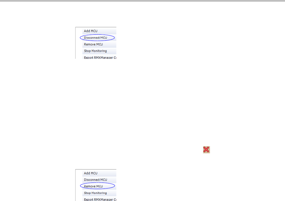
Chapter 18-RMX Manager Application
Polycom, Inc. 18-19
bRight-click the MCU icon and then click Disconnect MCU.
The MCU icon changes to disconnected and any ongoing conference running on that
MCU will not be monitored in this RMX Manager; they are removed from the
Conferences pane. This MCU can still be monitored and controlled by other users.
Removing an MCU from the MCUs Pane
An MCU can be removed from the RMX Manager. This function should be used if the MCU
hardware was disconnected and removed from the network.
To Remove an MCU from the list:
1Use one of the following methods:
aSelect the MCU to disconnect and click the Delete button.
bRight-click the MCU icon and then click Remove MCU.
A confirmation message is displayed.
2Click OK to confirm or Cancel to abort the operation.
The MCU icon is removed from the MCUs pane.
Changing the RMX Manager Language
You can change the language of the RMX Manager menus and dialog boxes. Only one
language can be selected at a time and the RMX Manager application must be restarted after
changing the display language.
To select a language:
1On the RMX Manager menu, click Setup > Customize Display Settings > Multilingual
Settings.
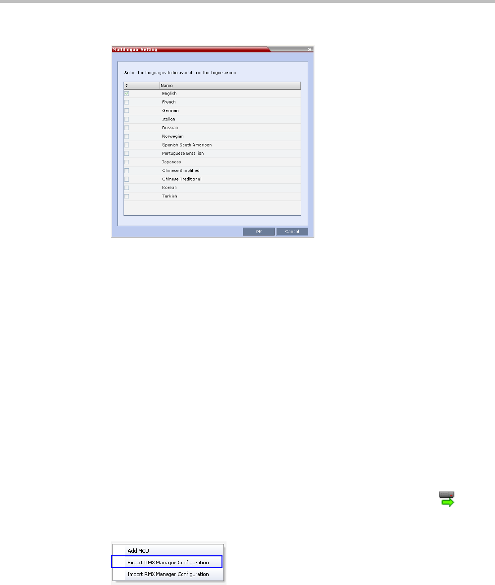
Polycom® RealPresence Collaboration ServerVirtual Edition Administrator’s Guide
18-20 Polycom, Inc.
The Multilingual Settings dialog box opens, displaying the current language selection.
2Click the check box of the required language. Only one language can be selected.
3Click OK.
4Restart the RMX Manager application to implement the language change.
Import/Export RMX Manager Configuration
The RMX Manager configuration that includes the MCU list and the multilingual selection
can be save to any workstation/PC on the network and imported to any Multi-RMX
Manager installed in the network. This enables the creation of the MCUs list once and
distributing it to all RMX Manager installations on the network.
In addition, when upgrading to a previous version, the MCU list is deleted, and can be
imported after upgrade.
The exported file is save in XML format and can be edited in any text editor that can open
XML files.
To Export the RMX Manager Configuration:
1In the Multi-RMX Manager, click the Export RMX Manager Configuration button
in the toolbar, or right-click anywhere in the MCUs pane and then click Export RMX
Manager Configuration.
The Export RMX Manager Configuration dialog box opens.
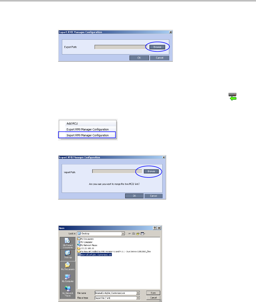
Chapter 18-RMX Manager Application
Polycom, Inc. 18-21
2Click the Browse button to select the location of the save file, or enter the required path
in the Export Path box.
The selected file path is displayed in the Export Path box.
3Click OK to export the RMX Manager configuration.
To Import the RMX Manager Configuration:
1In the Multi-RMX Manager, click the Import RMX Manager Configuration button
in the toolbar, or right-click anywhere in the MCUs pane and then click Import RMX
Manager Configuration.
The Import RMX Manager Configuration dialog box opens.
2Click the Browse button to select the saved file, or enter the required path in the Export
Path box.
The Open dialog box is displayed.
3Select the XML file previously saved, and click the Open button.
The selected file path is displayed in the Import Path box.
4Click OK to import the file.

Polycom® RealPresence Collaboration ServerVirtual Edition Administrator’s Guide
18-22 Polycom, Inc.
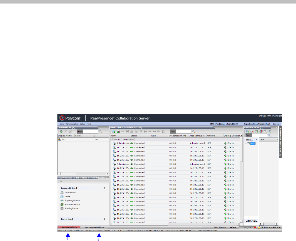
Polycom, Inc. 19-1
19
Collaboration Server Administration
and Utilities
System and Participant Alerts
The MCU alerts users to any faults or errors the MCU encountered during operation. Two
indication bars labeled System Alerts and Participant Alerts signal users of system errors by
blinking red in the event of an alert.
The System Alerts indication bar blinks red prompting the user to view the active alarms.
Once viewed, the System Alerts indication bar becomes statically red until the errors have
been resolved in the MCU.
The Participants Alerts indication bar blinks red indicating participant connection difficulties
in conferences. Once viewed, the Participant Alerts indication bar becomes statically red until
the errors have been resolved in the MCU.
System Alerts
System Alerts are activated when the system encounters errors such as a general or card
error. The system errors are recorded by the Collaboration Server and can be generated into a
report that can be saved in *.txt format.
System Alerts
indication bar
Participant Alerts
indication bar
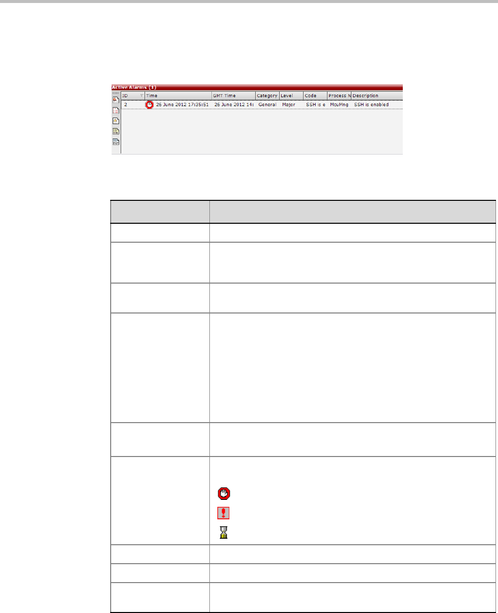
Polycom® RealPresence Collaboration ServerVirtual Edition Administrator’s Guide
19-2 Polycom, Inc.
To view the System Alerts list:
1Click the red blinking System Alerts indication bar.
The Active Alarms pane opens. This screen indicates what events have not been
resolved.
The following columns appear in the Active Alarms pane:
For more information about the Active Alarms, see Appendix B: "Active Alarms” on
page B-1.
Table 19-1 Active Alarms Pane Columns
Field Description
ID An identifying number assigned to the system alert.
Time Lists the local date and time that the error occurred. This column also
includes the icon indicating the error level (as listed in the level
column).
GMT Time Lists the date and time according to Greenwich Mean Time (GMT)
that the error occurred.
Category Lists the type of error. The following categories may be listed:
•File – indicates a problem in one of the files stored on the MCU’s
hard disk.
•Card – indicates problems with a card.
•Exception – indicates software errors.
•General – indicates a general error.
•Assert – indicates internal software errors that are reported by
the software program.
Category (cont.) •Startup – indicates errors that occurred during system startup.
•Unit – indicates problems with a unit.
Level Indicates the severity of the problem, or the type of event. There are
three fault level indicators:
– Major Error
– System Message
– Startup Event
Code Indicates the problem, as indicated by the error category.
Process Name Lists the type of functional process involved.
Description When applicable, displays a more detailed explanation of the cause
of the problem.
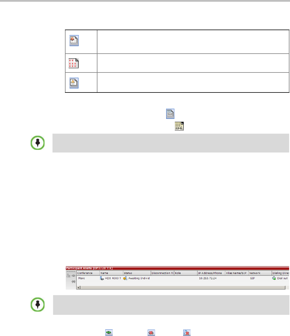
Chapter 19-Collaboration Server Administration and Utilities
Polycom, Inc. 19-3
2Click one of the following two buttons to view its report in the System Alerts pane:
3To save the Active Alarms, Faults Full List or Faults report:
—to a text file, click the Save to Text button
—to an XML file, click the Save to XML button
The Save dialog window opens.
4Select a destination folder and enter the file name.
5Click Save.
Participant Alerts
Participant Alerts
enables users, participants and conferences to be prompted and currently
connected. This includes all participants that are disconnected, idle, on standby or waiting for
dial-in. Alerts are intended for users or administrators to quickly see all participants that need
their attention.
To view the Participants Alerts list:
1Click the red blinking Participants Alerts indication bar.
The Participant Alerts pane opens.
2To resolve participant issues that created the Participant Alerts, the administrator can
either Connect , Disconnect or Delete a participant.
Active Alarms (default) – this is the default reports list that is displayed when
clicking the System Alerts indication bar. It displays the current system errors
and is a quick indicator of the MCU status.
Faults Full List - A list of all system faults.
Note: Viewed when logged in as a special support user.
Faults List – a list of faults that occurred previously (whether they were solved
or not) for support or debugging purposes.
The Save to XML button is only available when logged in as a special support user.
The Participant Alerts pane displays similar properties to that of the Participant List pane. For more
information, see the Polycom® RealPresence Collaboration Server Virtual Edition Getting Started
Guide, "Participant Level Monitoring” on page 3-49.
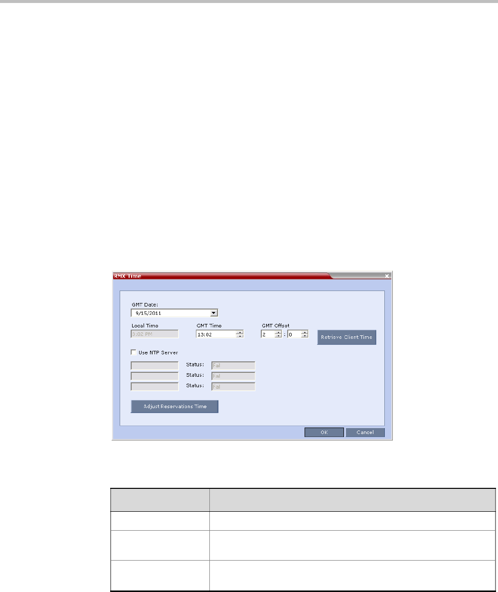
Polycom® RealPresence Collaboration ServerVirtual Edition Administrator’s Guide
19-4 Polycom, Inc.
RMX Time
To ensure accurate conference scheduling, the MCU has an internal clock that can function
in standalone mode, or in synchronization with up to three Network Time Protocol (NTP)
servers.
Guidelines
•NTP Version 4 is the only supported protocol.
• If applicable, daylight saving adjustments must be implemented by the administrator
whether the MCU is in standalone mode or synchronized with NTP Servers.
Altering the clock
The MCU’s date and time can be set manually or enabled to synchronize with external NTP
servers.
To Alter the MCU Time:
1On the Collaboration Server menu, click Setup > RMX Time to open the RMX Time
dialog box.
2View or modify the following fields:
Table 19-2 RMX Time – Fields Properties
Field Description
GMT Date The date at Greenwich, UK.
Local Time The MCU’s local time settings, are calculated from the GMT Time and
the GMT Offset.
GMT Time The MCU’s current GMT Time settings.
Select the Up or Down arrows to alter the GMT Time on the MCU.
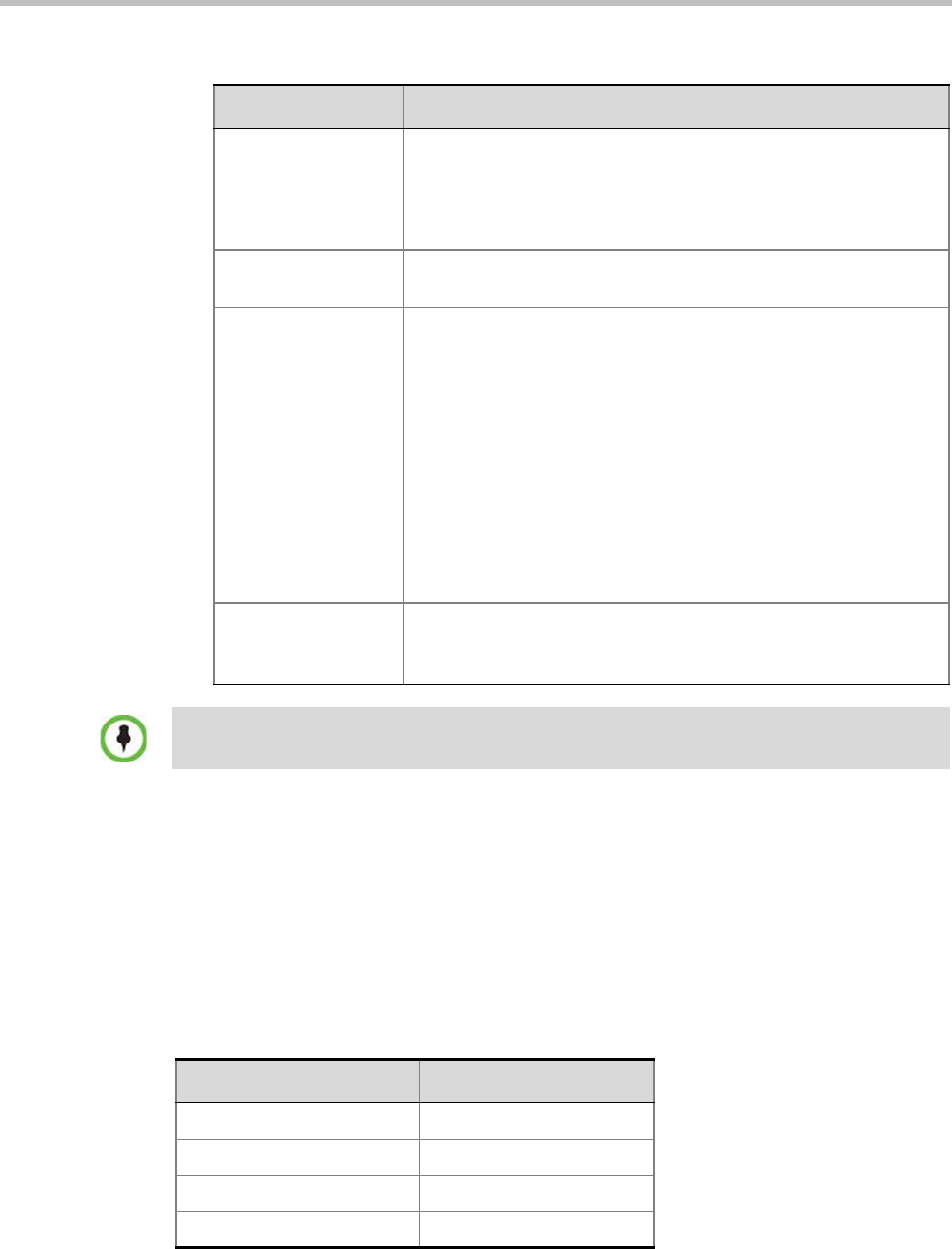
Chapter 19-Collaboration Server Administration and Utilities
Polycom, Inc. 19-5
Resource Management
Resource Capacity
The following table describes the resource capacity allocations for theRealPresence
Collaboration Server Virtual Edition per Resource type.
GMT Offset The time zone difference between Greenwich and the MCU’s
physical location in hours and minutes.
Select the Up or Down arrows to alter the GMT Offset time on the
MCU. To enter a negative offset either type a minus in the hour box or
use the down arrow and decrease the offset below zero.
Retrieve Client Time Click this button to automatically update the MCU’s GMT Date, Time
and Offset to match that of the workstation.
Use NTP Server Select this check box to synchronize the time with up to three NTP
servers. When selected, the manual GMT Date and GMT Time
setting options are disabled. The GMT Offset fields are still active.
To implement this mode an external connection to an NTP server
must be enabled.
Enter the IP addresses of the required NTP servers in order of
precedence.
The Status field indicates whether registration with the NTP Server
failed or succeeded.
Note: TheCollaboration Server will not use a time source such as a
Windows-based, W32Time service (SNTP) time service. Only full-
featured (below Stratum 16) NTP Servers are considered sufficiently
reliable for high-accuracy timing environments.
Adjust Reservations
Time
(Button)
Not supported in the RealPresence Collaboration Server.
After resetting the MCU a delay may occur when synchronizing with the external NTP server.
Table 19-2 RMX Time – Fields Properties (Continued)
Field Description
Table 19-4 System Resource Capacity Per Resource Type
Resource Type Number of Resources
VoIP Ports 120
CIF Ports 40
SD Ports (4CIF) 40
HD 720p30 Ports 20
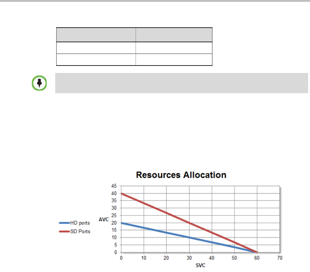
Polycom® RealPresence Collaboration ServerVirtual Edition Administrator’s Guide
19-6 Polycom, Inc.
In a mixed CP and SVC conference, video resources are used according to the amount of
both AVC and SVC participants in the conference. The ratio of resources in a mixed
conference is one AVC HD (720p30) video resource to three SVC video resources, meaning
for each AVC HD video resource, three SVC video resources can be allocated.
For example, in a mixed AVC/SVC conference, 10 HD AVC ports and 30 SVC ports can be
used, maintaining ratio of one HD port to three SVC ports.
The following diagram illustrates the amount of AVC to SVC port resources that are used in
a mixed AVC/SVC conference:
Resource Usage
SVC Conferencing
During a SVC conference, each SVC-endpoint uses one video port. One SVC resource is
equivalent to one AVC CIF resource. When sharing content an additional video resource is
used.
VGA RTV Ports 20
SVC Only Ports 60
Table 19-4 System Resource Capacity Per Resource Type
Resource Type Number of Resources
One SVC resource is equivalent to one AVC CIF resource.

Chapter 19-Collaboration Server Administration and Utilities
Polycom, Inc. 19-7
AVC Conferencing - Continuous Presence
Video resources usage varies according to the video resolution used by the endpoints. The
higher the video resolution (quality), the greater the amount of video resources consumed
by the MCU. Table 19-7 shows the number of video resources used for each resolution.
Table 19-5 CP Video Resource Usage vs. Resolution
Resolution/fps HD Video Resources Used
CIF/30
1/3 QCIF/30
SIF/30
WCIF/25
1/3
WSIF/30
432X336/30
SD/15
WSD/15
4CIF/15 1/3
WSD/30
2/3
4CIF/30
4SIF/30
WVGA/30
WVGA/25
480X352/30
SD/30
WSD/60
HD720p/30
Table 19-6 HD Video Resource Usage vs. Resolution
Resolution/fps HD Video Resources Used
H.261 CIF 30fps 2/3
H.263 CIF 30fps 1/3
H.263 4CIF 30fps 1/3
H.264 CIF 30fps 1/3
H.264 CIF 60fps 1/3
H.264 4CIF 30fps 1/3
H.264 4CIF 60fps 1/3
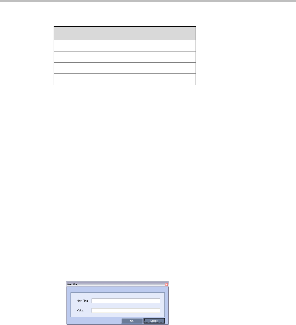
Polycom® RealPresence Collaboration ServerVirtual Edition Administrator’s Guide
19-8 Polycom, Inc.
AVC Conferencing - Voice
One CIF video resource equals 3 voice resources. All resources are taken from the same pool
of video resources.
Forcing Video Resource Allocation to CIF Resolution
You can set the MCU to allocate one CIF video resource to an endpoint, regardless of the
resolution determined by the Conference Profile parameters. This forcing saves resources
and enables more endpoints to connect to conferences.
The forcing is done by modifying the system configuration and it applies to all conferences
running on the MCU.
You can specify the endpoint types for which resource allocation can be forced to CIF
resource, enabling other types of endpoints to use higher resolutions in the same conference.
For example, you can force the system to allocate one CIF video resource to CMAD and VSX
endpoints while HDX endpoints can connect using SD or HD video resources.
Once the endpoint connects to the conference, its type is identified by the Collaboration
Server and, if applicable, the Collaboration Server will connect it using one CIF resource,
even if a higher resolution can be used.
To force CIF resource:
1On the Collaboration Server menu, click Setup > System Configuration.
The System Flags dialog box opens.
2In the MCMS_PARAMETERS tab, click the New Flag button.
The New Flag dialog box is displayed.
3In the New Flag field enter the flag name: FORCE_CIF_PORT_ALLOCATION
4In the Value field enter the product type to which the CIF resource should be allocated.
Possible values are:
—CMA Desktop for CMA desktop client
—VSX nnnn where nnnn represents the model number for example, VSX 8000.
H.264 720p 30fps 1/3
H.264 720p 60fps 2/3
H.264 1080p 25/30fps 2/3
H.264 1080p 50/60fps 4/3
Table 19-6 HD Video Resource Usage vs. Resolution
Resolution/fps HD Video Resources Used

Chapter 19-Collaboration Server Administration and Utilities
Polycom, Inc. 19-9
You can define several endpoint types, listing them one after the other separated by
semicolon (;).
For example, CMA Desktop;VSX 8000.
5Click OK.
The new flag is added to the flags list.
Reset the MCU for changes to take effect. For more details, see the Polycom® RealPresence
Collaboration Server Virtual Edition Administrator’s Guide, "Resetting the Collaboration Server”
on page 19-57.
To cancel the forcing of CIF resource:
1On the Collaboration Server menu, click Setup > System Configuration.
The System Flags dialog box opens.
2In the MCMS_PARAMETERS tab, double-click or select the flag
FORCE_CIF_PORT_ALLOCATION and click the Edit Flag button.
3In the New Value field, clear the value entries.
4Click OK.
Reset the MCU for changes to take effect. For more details, see the Polycom® RealPresence
Collaboration Server Virtual Edition Administrator’s Guide, "Resetting the Collaboration Server”
on page 19-57.
Resource Report
When viewing the Collaboration Server resource report, the resource allocations are
described in AVC HD units. A port ratio of 1 AVC HD port will equal 2 AVC SD ports,
which equals 3 SVC ports. This signifies that when the Collaboration Server is reporting the
available capacity, it will appropriately round up the remaining capacity to the nearest
whole value of available ports.
The Resource Report displays the real time resource usage. The Resource Report includes a
graphic representation of the resource usage. One resource report is available for all
resource usage including SVC-based endpoints.
Displaying the Resource Report
1In the main toolbar, click Administration > Resource Report.
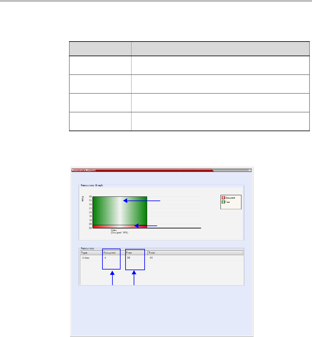
Polycom® RealPresence Collaboration ServerVirtual Edition Administrator’s Guide
19-10 Polycom, Inc.
For each resource type, the Resource Report includes the following columns:
•
The Resource Report dialog box is displayed, showing the resource usage according to
the Resource Capacity Mode.
Resource usage is displayed for video resources only. They are displayed as
percentages of the total resources.
The actual number of occupied or free resources can also be displayed by moving the
cursor over the columns of the bar graph. Moving the cursor over the Video bar displays
the following:
Table 19-8 Resource Report Fields Parameters
Column Description
Type This is always Video. This applies to both AVC and SVC-based
endpoints (and resources).
Occupied The number of MCU resources that are used by connected AVC and
SVC-based participants or reserved for defined participants.
Free The number of MCU resources available for connecting AVC and
SVC-based endpoints.
Total The Total column displays the total number of resources of that type
(Occupied and Free).
Video Resources
Free (%)
Video Resources
Occupied (%)
Actual Number of Occupied and Free Audio and Video Resources
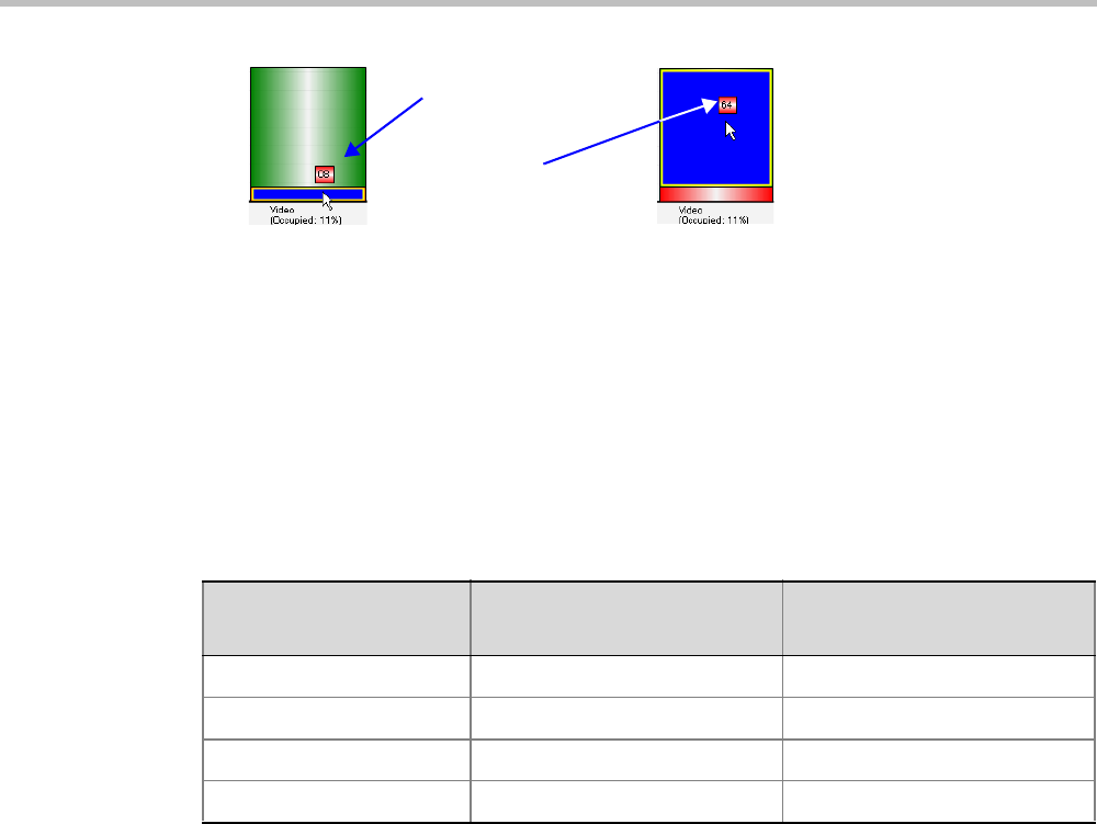
Chapter 19-Collaboration Server Administration and Utilities
Polycom, Inc. 19-11
When viewing the Collaboration Server resource report for mixed CP and SVC conferences,
the resource allocations are described in AVC HD720p30 units. A port ratio of 1 AVC HD
port will equal 2 AVC SD ports, which equals 3 SVC ports (in a non-mixed conference).
When the Collaboration Server is reporting the available capacity, it will appropriately
round up the remaining capacity to the nearest whole value of available ports. For example,
one SVC endpoint in a conference is equal to 1/3 of the resource value. The resource report
displays this as one full resource used. Two SVC endpoints is equal to 2/3 of the resource
value. Therefore, the resource report displays this as one full resource used, and so forth.
The following table explains the actual resource capacity utilization for both CP only and
mixed CP and SVC conferences:
* Resources are consumed at this rate only after the conference contains mixed endpoints.
T
MCU Resource Management by RealPresence Resource Manager (XMA),
Polycom CMA and Polycom RealPresence DMA System
When the RealPresence Resource Manager (XMA), Polycom CMA and Polycom
RealPresence DMA system are part of the solution, following a request by the RealPresence
Resource Manager (XMA), Polycom CMA or Polycom RealPresence DMA system, the MCU
will send updates on resource usage to both CMA and DMA, with each application
updating its own resource usage for the MCU. This provides better management of the
Collaboration Server resources by the RealPresence Resource Manager (XMA), Polycom CMA
and Polycom RealPresence DMA system.
Guidelines
• Following requests sent by CMA and RealPresence DMA system, the Collaboration Server
will send the number of occupied resources for a conference or total for the MCU.
• Occupied resources are resources that are connected to ongoing conferences.
Disconnected endpoints in an ongoing conference are not counted as occupied
resources.
Table 19-9 Resource Capacity Allocation Per Port Type
Port Type Non-Mixed Conferences Mixed CP and SVC
Conferences
AVC HD 1 1.5 *
AVC SD 0.5 0.75 *
AVC CIF 0.333 0.75 *
SVC 0.333 0.333
8 Occupied Video
Resources
64 Free Video
Resources
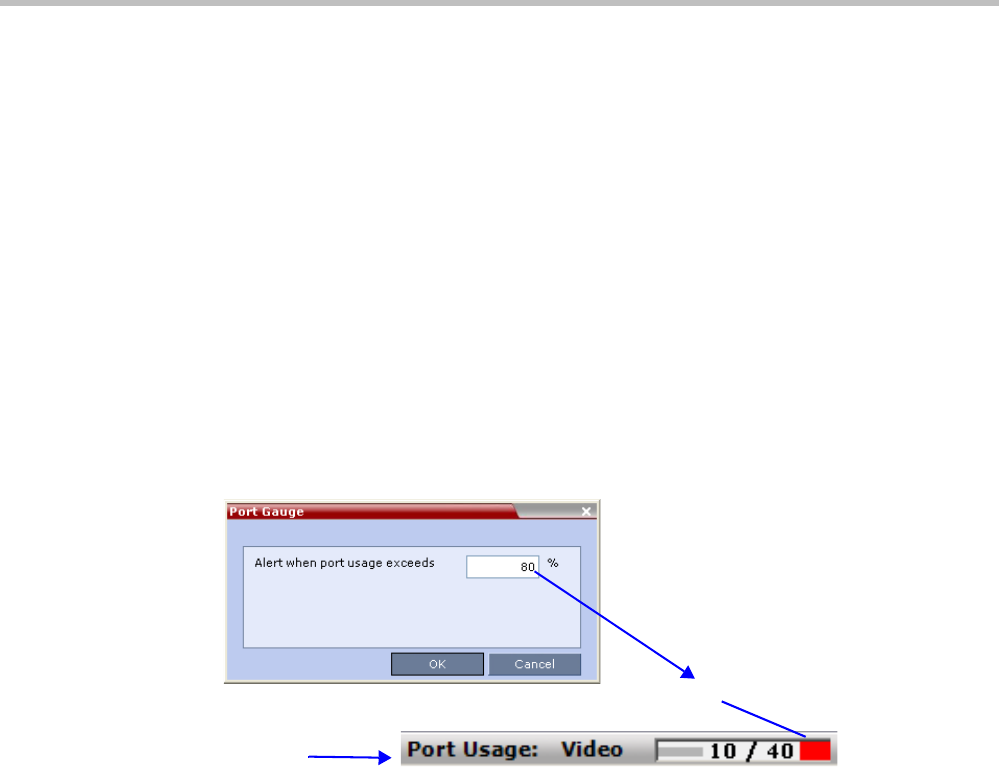
Polycom® RealPresence Collaboration ServerVirtual Edition Administrator’s Guide
19-12 Polycom, Inc.
• The Collaboration Server is unaware of the resource usage split between the CMA and
RealPresence DMA system.
Port Usage Threshold
The Collaboration Server can be set to alert the administrator to potential port capacity
shortages. A capacity usage threshold can be set as a percentage of the total number of
licensed ports in the system.
When the threshold is exceeded, a System Alert is generated.
The default port capacity usage threshold is 80%.
The administrator can monitor the MCU’s port capacity usage via the Port Gauge in the
Status Bar of the Collaboration Server Web Client.
Setting the Port Usage Threshold
To Set the Port Usage Threshold:
1In the Setup menu, click Port Gauge to open the Port Gauge dialog box.
Enter the value for the percentage capacity usage threshold.
The high Port Usage threshold represents a percentage of the total number of video
available. It is set to indicate when resource usage is approaching its maximum,
resulting in no free resources to run additional conferences. When port usage reaches or
exceeds the threshold, the red area of the gauge flashes. The default port usage
threshold is 80%.
2Click OK.
SIP Dial-in Busy Notification
When the system flag SEND_SIP_BUSY_UPON_RESOURCE_THRESHOLD is set to YES
(NO is the default), it enables the MCU to send a busy notification to a SIP audio endpoint
or a SIP device when dialing in to the MCU whose audio resource usage exceeded the Port
Usage threshold.
The Collaboration Server will send a SIP busy response to SIP audio endpoints when:
• The system flag SEND_SIP_BUSY_UPON_RESOURCE_THRESHOLD is set to YES
(NO is the default)
Status Bar
Usage Threshold
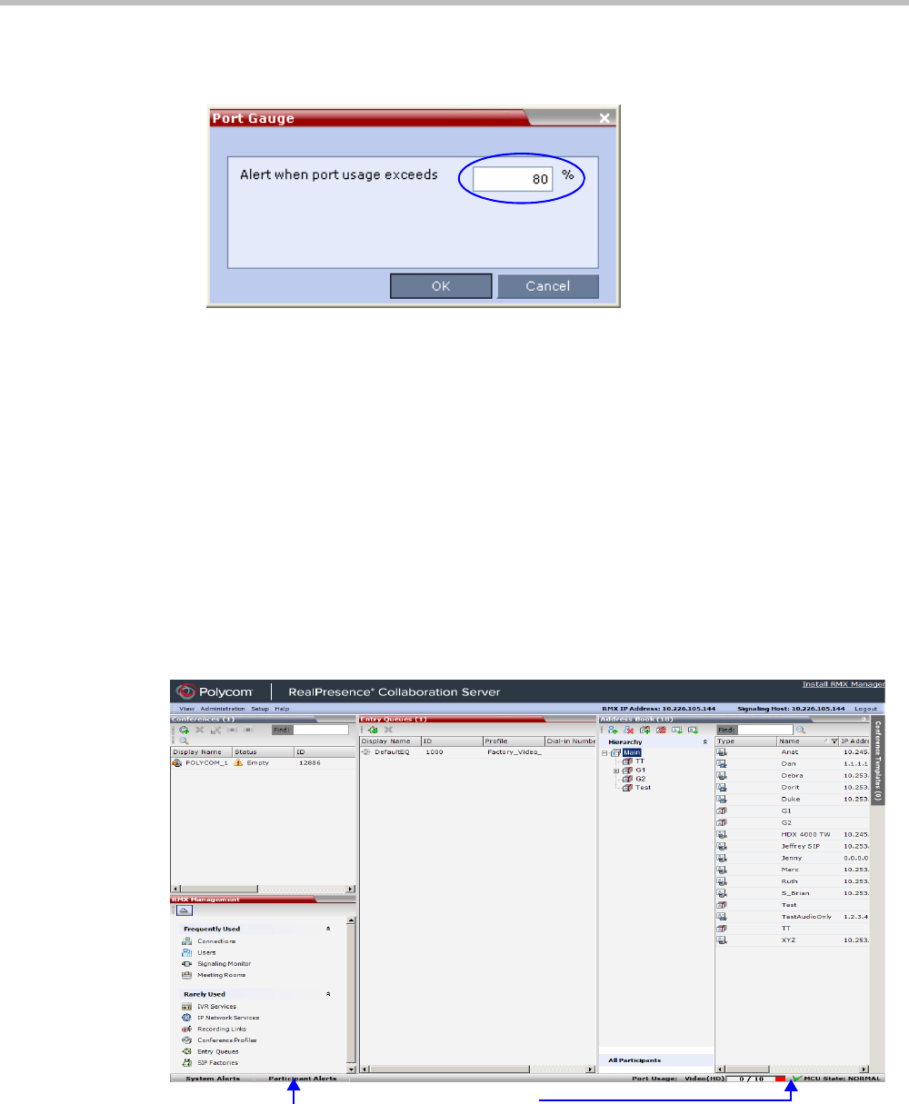
Chapter 19-Collaboration Server Administration and Utilities
Polycom, Inc. 19-13
• The port usage threshold for Audio resources is exceeded. The threshold is defined in
the Setup > Port Gauge dialog box.
When the flag is set to YES, the system will allow SIP audio endpoints to connect to the
MCU until the Port Usage threshold is reached. Once this threshold is exceeded, the SIP
audio endpoints will not be able to connect, ensuring that the remaining system resources
can be used by all other connections, including SIP video, and H.323 cascaded links. When
the call is rejected by the MCU because of lack of resources, the appropriate indication will
be sent by the MCU to the SIP audio endpoint.
For example, if the Port Gauge threshold is set to 80%, when 80% of the Audio resources are
used, the system will not allow additional SIP audio endpoints to connect and will send a
busy notification to the endpoint.
This does not affect the video resources usage.
Port Usage Gauge
The Port Usage Gauge is displayed in the Status Bar at the bottom of the Collaboration Server
Web Client screen.
The Port Usage gauge indicates:
• The total number of Video ports in the system
Status Bar Port Usage Gauge

Polycom® RealPresence Collaboration ServerVirtual Edition Administrator’s Guide
19-14 Polycom, Inc.
• The number of Video ports in use.
•The High Port Usage threshold.
The basic unit used for reporting resource usage in the Port Gauges is HD720p30.
Results are rounded to the nearest integer.
Video Port Usage Indicator
Total Allocated Video Ports In System
Video Ports In Use
Video Port Usage Threshold
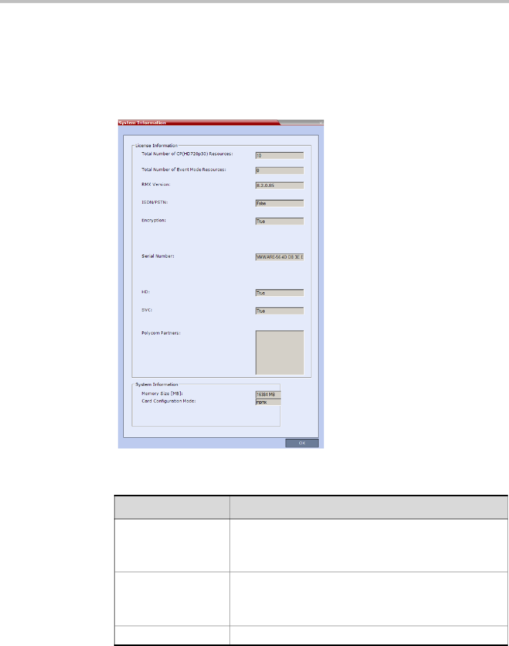
Chapter 19-Collaboration Server Administration and Utilities
Polycom, Inc. 19-15
System Information
System Information includes License Information and general system information.
To view the System Information properties box:
>> On the menu, click Administration > System Information.
The System Information properties box is displayed.
The System Information properties box displays the following information:
Table 19-11 System Information
Field Description
Total Number of
CP(HD720p30)
Resources
Displays the number of HD720p30 video participants licensed for
the system. Each HD720p30 resource represents one 3 CIF video
resources. Each SVC resource is equivalent to one CIF video
resource.
Total Number of Event
Mode Resources
Displays the number of video/voice participants licensed for a
system in Event Mode Licensing. It also determines the
conference type that is available on the system.
0 - indicates that this Licensing mode is disabled for this system.
RMX™ Version Displays the System Software Version of the RMX™.

Polycom® RealPresence Collaboration ServerVirtual Edition Administrator’s Guide
19-16 Polycom, Inc.
Encryption Indicates whether Encryption is included in the MCU license.
Encryption is not available in all countries.
Range: True / False
Serial Number Displays the Serial Number of the Collaboration Server unit.
HD Indicates if the MCU is licensed to connect endpoints at HD
resolutions in Continuous Presence conferences.
SVC license.
Polycom Partners Indicates that the System Software contains features for the
support of specific Polycom Partner environments.
Table 19-11 System Information (Continued)
Field Description

Chapter 19-Collaboration Server Administration and Utilities
Polycom, Inc. 19-17
SNMP (Simple Network Management Protocol)
SNMP enables managing and monitoring of the MCU status by external managing systems,
such as HP OpenView or through web applications.
The Collaboration Server’s implementation of SNMPv3 is FIPS 140 compliant.
MIBs (Management Information Base)
MIBs are a collection of definitions, which define the properties of the managed object
within the device to be managed. Every managed device keeps a database of values for each
of the definitions written in the MIB.
The SNMP systems poll the MCU according to the MIB definitions.
Traps
The MCU is able to send Traps to different managers. Traps are messages that are sent by
the MCU to the SNMP Manager when an event such as MCU Reset occurs.
Guidelines
•Version 1, Version 2 and Version 3 traps are supported.
• When SNMPv3 is selected only SNMPv3 Queries and Traps receive responses.
•A mixture of Version 1, Version 2 and Version 3 traps is not permitted.
MIB Files
The H.341 standard defines the MIBs that H.320 and H.323 MCUs must comply with. In
addition, other MIBs should also be supported, such as MIB-II and the ENTITY MIB, which
are common to all network entities.
The MIBs are contained in files in the SNMP MIBS sub-directory of the Collaboration Server
root directory. The files should be loaded to the SNMP external system and compiled within
that application. Only then can the SNMP external application perform the required
monitoring tasks.
Private MIBs
•RMX-MIB (RMX-MIB.MIB)
—Contains the statuses of the Collaboration Server: Startup, Normal and Major.
—Contains all the Alarms of the Collaboration Server that are sent to the SNMP
Manager.
The MULTI-MEDIA_MIB_TC must be compiled before compiling the other MIBs.

Polycom® RealPresence Collaboration ServerVirtual Edition Administrator’s Guide
19-18 Polycom, Inc.
Support for MIB-II Sections
The following table details the MIB-II sections that are supported:
The Alarm-MIB
MIB used to send alarms. When a trap is sent, the Alarm-MIB is used to send it.
H.341-MIB (H.341 – H.323)
• Gives the address of the gatekeeper.
• Supports H.341-MIB of SNMP events of H.323.
Standard MIBs
This section describes the MIBs that are included with the Collaboration Server. These MIBs
define the various parameters that can be monitored, and their acceptable values.
Table 19-12 Supported MIB-II Sections
Section Object Identifier
system mib-2 1
interfaces mib-2 2
ip mib-2 4
Table 19-13 Standard MIBs
MIB Name Description
MULTI-MEDIA-MIB-TC
(MULTIMTC.MIB)
Defines a set of textual conventions used within the set of Multi Media
MIB modules.
H.320ENTITY-MIB
(H320-ENT.MIB)
This is a collection of common objects, which can be used in an H.320
terminal, an H.320 MCU and an H.320/H.323 gateway. These objects
are arranged in three groups: Capability, Call Status, and H.221
Statistics.
H.320MCU-MIB (H320-
MCU.MIB)
Used to identify managed objects for an H.320 MCU. It consists of four
groups: System, Conference, Terminal, and Controls. The Conference
group consists of the active conferences. The Terminal group is used to
describe terminals in active MCU conferences. The Controls group
enables remote management of the MCU.
H323MC-MIB (H323-
MC.MIB)
Used to identify objects defined for an H.323 Multipoint Controller. It
consists of six groups: System, Configuration, Conference, Statistics,
Controls and Notifications. The Conference group is used to identify the
active conferences in the MCU. The Notifications group allows an MCU,
if enabled, to inform a remote management client of its operational
status.
Note: The Collaboration Server supports only one field in H.341-
H323MC MIB. The Collaboration Server reports the Gatekeeper
address using H.341-H323MC MIB – 323McConfigGatekeeperAddress
(0.0.8.341.1.1.4.2.1.1.4) in response to a query from a manager.

Chapter 19-Collaboration Server Administration and Utilities
Polycom, Inc. 19-19
Unified MIB
The Collaboration Server uses the Polycom Unified MIB, in addition to the RMX specific
MIB. The Polycom Unified MIB is an MIB that is used by many Polycom products. The
following table describes the information provided by the Collaboration Server in the
Unified MIB.
MP-MIB (H323-MP.MIB) Used to identify objects defined for an H.323 Multipoint Processor, and
consists of two groups: Configuration and Conference. The
Configuration group is used to identify audio/video mix configuration
counts. The Conference group describes the audio and video multi-
processing operation.
MIB-II/RFC1213-MIB
(RFC1213.MIB)
Holds basic network information and statistics about the following
protocols: TCP, UDP, IP, ICMP and SNMP. In addition, it holds a table of
interfaces that the Agent has. MIB-II also contains basic identification
information for the system, such as, Product Name, Description,
Location and Contact Person.
ENTITY-MIB
(ENTITY.MIB)
Describes the unit physically: Number of slots, type of board in each
slot, and number of ports in each slot.
Table 19-14 Unified MIB SNMP Fields
Name Type Description
Debug Boolean Indicates whether the unit is in a debugging state.
IncomingCallsReqrGK Boolean Indicates whether a gatekeeper is required to
receive incoming H.323 calls.
OutgoingCallsReqrGK Boolean Indicates whether a gatekeeper is required to make
outgoing H.323 calls.
HDBitrateThrshld Integer The minimum bit rate required by endpoints in order
to connect to an HD conference.
MaxCPRstln Integer Maximum resolution of a CP conference.
MaxCPRstlnCfg Integer Configured resolution for a CP conference.
EndpointDispayName String The name of the MCU that is displayed on the
screen of endpoints that are connecting to the
conference.
PALNTSC NTSC/PAL/
AUTO
The video encoding of the RMX.
SeparateMgmtNet Boolean Indicates whether management network separation
is enabled.
NumPorts Integer Total number of ports.
NumVideoPorts Integer Number of ports configured for video.
Table 19-13 Standard MIBs
MIB Name Description

Polycom® RealPresence Collaboration ServerVirtual Edition Administrator’s Guide
19-20 Polycom, Inc.
ServiceH323 Integer Indicates the status of H.323 capabilities:
1 - The service is enabled and operational.
2 - The service is enabled but is not operational.
3 - The service is disabled.
ServiceSIP Integer Indicates the status of SIP capabilities:
1 - The service is enabled and operational.
2 - The service is enabled but is not operational.
3 - The service is disabled.
ServiceISDN Integer Indicates the status of SIP capabilities:
1 - The service is enabled and operational.
2 - The service is enabled but is not operational.
3 - The service is disabled.
RsrcAllocMode Fixed/
Flexible
The resource allocation method which determines
how the system resources are allocated to the
connecting endpoints.
McuSystemStatus Integer System State.
FanStatus Boolean Status of the hardware fan.
PowerSupplyStatus Boolean Status of the power supply.
IntegratedBoardsStatus Boolean Status of the integrated boards.
UltraSecureMode Boolean Indicates whether the RMX is operating in Ultra
Secure Mode.
ChassisTemp Integer The temperature of the chasis.
NumPortsUsed Integer Number of ports currently in use.
NewCallsPerMinute Integer New calls in the last minute.
ScsfNewCallsPerMinute Integer Successful new calls in the last minute.
FldNewCallsPerMinute Integer Failed new calls in the last minute.
PctScsflNewCalls Integer Percentage of new calls in the last minute which
were successful.
CallsEndedScsflPerMin Integer Number of calls in the last minute which ended with
a success code.
CallsEndedFailedPerMin Integer Number of calls in the last minute which ended with
a failure code.
CallsEndedScsfl Integer Number of calls in the last minute which ended with
a success code.
CallsEndedFailed Integer Number of calls in the last minute which ended with
a failure code.
NumActvCnfrncs Integer Number of active conferences.
Table 19-14 Unified MIB SNMP Fields (Continued)
Name Type Description

Chapter 19-Collaboration Server Administration and Utilities
Polycom, Inc. 19-21
Traps
Three types of traps are sent as follows:
1ColdStart trap. This is a standard trap which is sent when the MCU is reset.
Figure 1 An Example of a ColdStart Trap
2Authentication failure trap. This is a standard trap which is sent when an unauthorized
community tries to enter.
Figure 2 An Example of an Authentication Failure Trap
coldStart notification received from: 172.22.189.154 at 5/20/
2007 7:03:12 PM
Time stamp: 0 days 00h:00m:00s.00th
Agent address: 172.22.189.154 Port: 32774 Transport: IP/UDP
Protocol: SNMPv2c Notification
Manager address: 172.22.172.34 Port: 162 Transport: IP/UDP
Community: public
Enterprise: enterprises.8072.3.2.10
Bindings (3)
Binding #1: sysUpTime.0 *** (timeticks) 0 days
00h:00m:00s.00th
Binding #2: snmpTrapOID.0 *** (oid) coldStart
authentication Failure notification received from:
172.22.189.154 at 5/20/2007 7:33:38 PM
Time stamp: 0 days 00h:30m:27s.64th
Agent address: 172.22.189.154 Port: 32777 Transport: IP/UDP
Protocol: SNMPv2c Notification
Manager address: 172.22.172.34 Port: 162 Transport: IP/UDP
Community: public
Enterprise: enterprises.8072.3.2.10
Bindings (3)
Binding #1: sysUpTime.0 *** (timeticks) 0 days
00h:30m:27s.64th
Binding #2: snmpTrapOID.0 *** (oid) authenticationFailure

Polycom® RealPresence Collaboration ServerVirtual Edition Administrator’s Guide
19-22 Polycom, Inc.
3Alarm Fault trap. The third trap type is a family of traps defined in the POLYCOM-
RMX-MIB file, these traps are associated with the Collaboration Server active alarm and
clearance (proprietary SNMP trap).
Figure 3 An Example of an Alarm Fault Trap
Each trap is sent with a time stamp, the agent address, and the manager address.
Status Trap
The MCU sends status traps for the status MAJOR - a trap is sent when the card/MCU
status is MAJOR.
All traps are considered “MAJOR”.
RMX MIB entities that do not generate traps.
The following table lists the entities that appear in the RMX MIB of the SNMP that do not
generate traps. These traps will be displayed as Faults in the System Alerts pane (at the
bottom of the Collaboration Server (RMX) Web Client screen.
Table 19-15 SNMP MIB entities that do not generate traps
Key Description Comment
5002 Resource process did not receive the Meeting Room list during
startup.
5004 Task terminated
5008 Low Processing Memory
5009 Low system Memory
5010 High system CPU usage
5014 High CPU utilization
rmxFailedConfigUserListInLinuxAlarmFault notification received
from: 172.22.189.154 at 5/20/2007 7:04:22 PM
Time stamp: 0 days 00h:01m:11s.71th
Agent address: 172.22.189.154 Port: 32777 Transport: IP/UDP
Protocol: SNMPv2c Notification
Manager address: 172.22.172.34 Port: 162 Transport: IP/UDP
Community: public
Bindings (6)
Binding #1: sysUpTime.0 *** (timeticks) 0 days
00h:01m:11s.71th
Binding #2: snmpTrapOID.0 *** (oid)
rmxFailedConfigUserListInLinuxAlarmFault
Binding #3: rmxAlarmDescription *** (octets) Insufficient
resources
Binding #4: rmxActiveAlarmDateAndTime *** (octets) 2007-6-
19,16:7:15.0,0:0
Binding #5: rmxActiveAlarmIndex *** (gauge32) 2
Binding #6: rmxActiveAlarmListName *** (octets) Active
Alarm Table
* Binding #7: rmxActiveAlarmRmxStatus *** (rmxStatus) major

Chapter 19-Collaboration Server Administration and Utilities
Polycom, Inc. 19-23
5016 Process idle
5107 Failed to open Apache server configuration file
5108 Failed to save Apache server configuration file
5110 A private version is loaded
5111 NTP synchronization failure
5112 Invalid date and time
5116 Incorrect Ethernet Settings
5117 Smart Report found errors on hard disk
5118 Invalid MCU Version
5150 Music file error
5205 Unspecified problem
5207 Unit not responding
5209 Failed to mount Card folder
5401 The Log file system is disabled
5450 Action redirection failure
5601 Process terminated
5602 Terminal initiated MCU reset
5603 User initiated MCU reset
5604 Internal MCU reset
5605 MCU reset
5606 MCU Reset to enable Diagnostics mode
5607 Startup process failure
5801 Polycom default User exists. For security reasons, it is recommended
to delete this User and create your own User.
Only in non-
Ultra Secure
Mode
5904 Single clock source
5950 MCU is not configured for AVF gatekeeper mode
5652 Hard disk error /AA_HARD_DISK_FAILURE Not in use
5551 Port configuration modified Not in use
5011 Used for testing the Active Alarms mechanism Not in use
Table 19-15 SNMP MIB entities that do not generate traps (Continued)
Key Description Comment
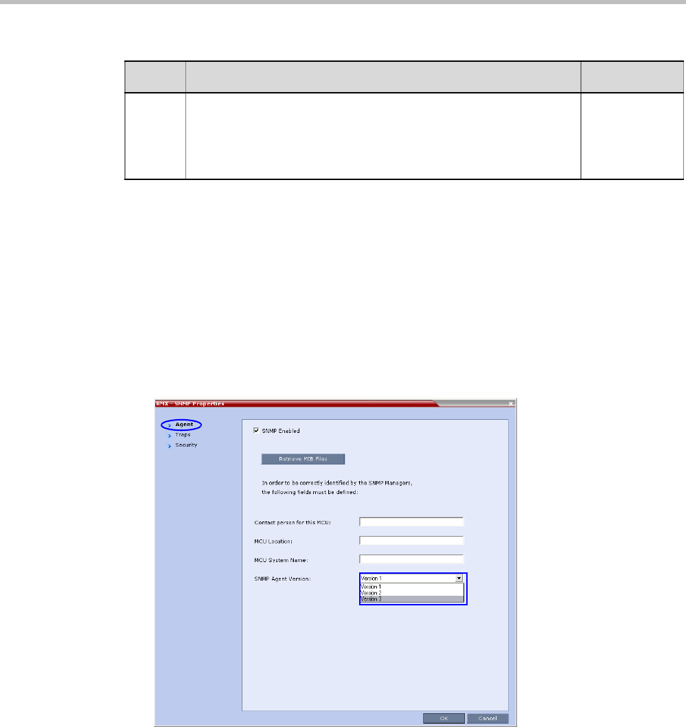
Polycom® RealPresence Collaboration ServerVirtual Edition Administrator’s Guide
19-24 Polycom, Inc.
Defining the SNMP Parameters in the Collaboration Server
The SNMP option is enabled via the Collaboration Server Web Client application.
The addresses of the Managers monitoring the MCU and other security information are
defined in the Collaboration Server Web Client application and are saved on the MCU’s hard
disk. Only users defined as Administrator can define or modify the SNMP security
parameters in the Collaboration Server Web Client application.
To enable SNMP option:
1In the Collaboration Server Web Client menu bar, click Setup > SNMP.
The Collaboration Server-SNMP Properties - Agent dialog box is displayed.
This dialog box is used to define the basic information for this MCU that will be used by
the SNMP system to identify it.
2In the Agent dialog box, click the SNMP Enabled check box.
3Click the Retrieve MIB Files button to obtain a file that lists the MIBs that define the
properties of the object being managed.
The Retrieve MIB Files dialog box is displayed.
4Click the Browse button and navigate to the desired directory to save the MIB files.
5001 License not found Not in use
(Product
activation
failure is
trapped)
Table 19-15 SNMP MIB entities that do not generate traps (Continued)
Key Description Comment
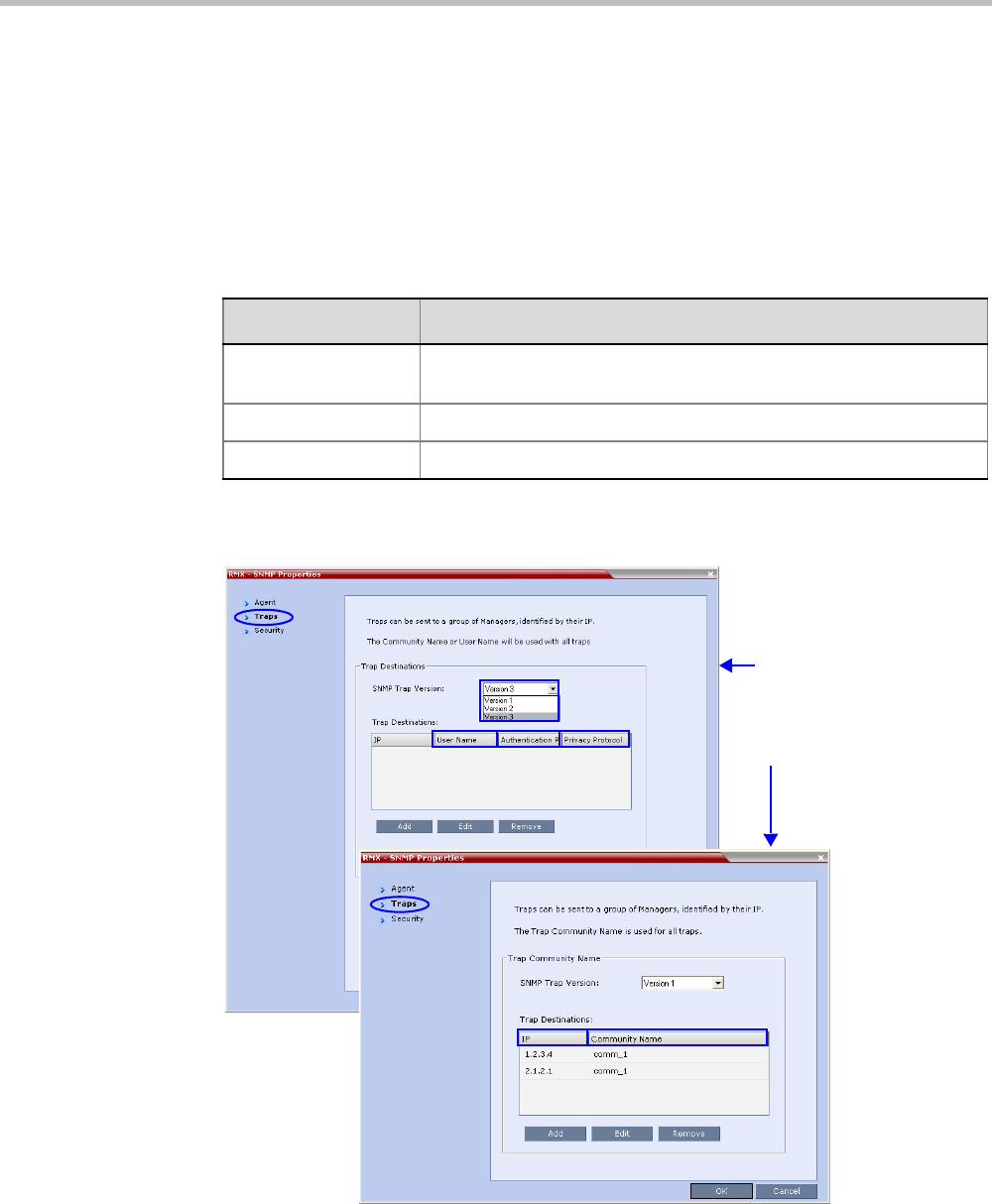
Chapter 19-Collaboration Server Administration and Utilities
Polycom, Inc. 19-25
5Click OK.
The path of the selected directory is displayed in the Retrieve MIB Files dialog box.
6Click the Save button.
The MIB files are saved to the selected directory.
7Click Close to exit the Retrieve MIB Files dialog box.
8In the Agent dialog box, define the parameters that allow the SNMP Management
System and its user to easily identify the MCU.
9Click the Traps tab.
The Collaboration Server-SNMP Properties – Traps dialog box opens.
Traps are messages sent by the MCU to the SNMP Managers when events such as MCU
Startup or Shutdown occur. Traps may be sent to several SNMP Managers whose IP
addresses are specified in the Trap Destinations box.
Table 19-16 Collaboration Server-SNMP Properties - Agent Options
Field Description
Contact person for
this MCU
Type the name of the person to be contacted in the event of problems
with the MCU.
MCU Location Type the location of the MCU (address or any description).
MCU System Name Type the MCU’s system name.
Versions 1 & 2
Version 3

Polycom® RealPresence Collaboration ServerVirtual Edition Administrator’s Guide
19-26 Polycom, Inc.
10 Define the following parameters:
11 Click the Add button to add a new Manager terminal.
Table 19-17 SNMPv3 - Traps
Field Description
SNMP Trap Version Specifies the version, either Version 1 2 or 3 of the traps being sent to
the IP Host. Polycom software supports the standard SNMP version 1
and 2 traps, which are taken from RFC 1215, convention for defining
traps for use with SNMP.
Note: The SNMP Trap Version parameters must be defined
identically in the external SNMP application.
Trap Destination This box lists the currently defined IP addresses of the Manager
terminals to which the message (trap) is sent.
IP Enter the IP address of the SNMP
trap recipient.
All
Versions
Community
Name
Enter the Community Name of the
manager terminal used to monitor
the MCU activity
Version 1
and
Version 2
User Name Enter the name of the user who is to
have access to the trap.
Version 3
Authentication
Protocol
Enter the authentication protocol:
MD5 or SHA.
Privacy
Protocol
Enter the privacy protocol: DES or
AES.
Engine ID Enter an Engine ID to be used for
both the Agent and the Trap.
Default: Empty
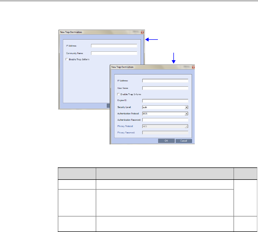
Chapter 19-Collaboration Server Administration and Utilities
Polycom, Inc. 19-27
Depending on the SNMP Trap Version selected, one of the two following New Trap
Destination dialog boxes opens.
12 Define the following parameters:
Trap Version 1 ,2
Trap Version 3
Table 19-18 SNMPv3 - Traps
Field Description Version
IP Address Enter the IP address of the SNMP trap recipient.
1,2,3
Enable Trap
Inform
An Inform is a Trap that requires receipt confirmation from the
entity receiving the Trap. If the Engine ID field (Version 3) is
empty when Enable Trap Inform has been selected, the Engine
ID is set by the Client.
Community
Name
Enter the Community Name of the manager terminal used to
monitor the MCU activity 1, 2

Polycom® RealPresence Collaboration ServerVirtual Edition Administrator’s Guide
19-28 Polycom, Inc.
13 Type the IP Address and the Community name of the manager terminal used to
monitor the MCU activity, and then click OK.
The Community name is a string of characters that will be added to the message that is
sent to the external Manager terminals. This string is used to identify the message
source by the external Manager terminal.
The new IP Address and Community name is added to the Trap Destinations box.
aTo delete the IP Address of a Manager terminal, select the address that you wish to
delete, and then click the Remove button.
The IP address in the Trap Destinations box is removed.
14 Click the Security tab.
User Name Enter the name of the user who is to have access to the trap.
3
Engine ID Enter an Engine ID to be used for the Trap.
This field is enabled when the Enable Trap Inform check box is
selected. If the Enable Trap Inform check box is cleared the
Engine ID of the Agent is used. The Engine ID is comprised of
up to 64 Hexadecimal characters.
Default: Empty
Security Level Select a Security Level from the drop-down menu.
Range: No Auth, No Priv; Auth, No Priv; Auth, Priv
Default: Auth, Priv
Authentication
Protocol
Enter the authentication protocol: MD5 or SHA.
The availability of the MD5 Authentication Protocol as a
selectable option is controlled by adding the
SNMP_FIPS_MODE System Flag to system.cfg and setting its
value. A value of YES means that MD5 will neither be displayed
as selectable option nor supported.
Range: YES/NO.
Default: NO.
Authentication Password
Privacy
Protocol
Enter the privacy protocol: DES or AES.
The availability of the DES Privacy Protocol as a selectable
option is controlled by adding the SNMP_FIPS_MODE System
Flag to system.cfg and setting its value. A value of YES means
that DES will neither be displayed as a selectable option nor
supported.
Range: YES/NO.
Default: NO.
Privacy Password
Table 19-18 SNMPv3 - Traps (Continued)
Field Description Version
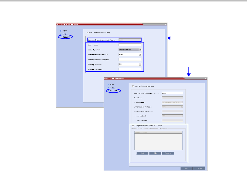
Chapter 19-Collaboration Server Administration and Utilities
Polycom, Inc. 19-29
The Collaboration Server-SNMP Properties – Security dialog box opens.
This dialog box is used to define whether the query sent to the MCU is sent from an
authorized source. When the “Accept SNMP packets from all Hosts” is disabled, a valid
query must contain the appropriate community string and must be sent from one of the
Manager terminals whose IP address is listed in this dialog box.
Versions 1 & 2
Version 3

Polycom® RealPresence Collaboration ServerVirtual Edition Administrator’s Guide
19-30 Polycom, Inc.
15 Define the following parameters:
Table 19-19 SNMP - Security
Field Description
Send Authentication
Trap
Select this check box to send a message to the SNMP
Manager when an unauthorized query is sent to the MCU.
When cleared, no indication will be sent to the SNMP
Manager.
Versions
1 & 2
Accept Host
Community Name
Enter the string added to queries that are sent from the SNMP
Manager to indicate that they were sent from an authorized
source.
Note: Queries sent with different strings will be regarded as a
violation of security, and, if the Send Authentication Trap
check box is selected, an appropriate message will be sent to
the SNMP Manager.
Accept SNMP
Packets from all Host
Select this option if a query sent from any Manager terminal is
valid. When selected, the Accept SNMP Packets from These
Hosts option is disabled.
Accept SNMP
Packets from the
following Hosts
Lists specific Manager terminals whose queries will be
considered as valid. This option is enabled when the Accept
SNMP Packets from any Host option is cleared.
User Name Enter a User Name of up to 48 characters
Default: Empty
Version
3
Security Level Select a Security Level from the drop-down menu.
Range: No Auth, No Priv; Auth, No Priv; Auth, Priv
Default: Auth, Priv
Authentication
Protocol
Select the authentication
protocol
Range: MD5, SHA
Default: MD5 These fields are enabled if
Authentication is selected
in the Security Level field.
Authentication
Password
Enter an Authentication
Password.
Range: 8 - 48 characters
Default: Empty
Privacy Protocol Select a Privacy Protocol.
Range: DES, AES
Default: DES
These fields are enabled if
Privacy is selected in the
Security Level field.
Privacy Password Enter a Privacy Password.
Range: 8 - 48 characters
Default: Empty
Engine ID Enter an Engine ID to be used
for both the Agent and the Trap.
Default: Empty
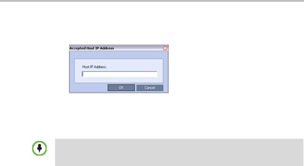
Chapter 19-Collaboration Server Administration and Utilities
Polycom, Inc. 19-31
16 To specifically define one or more valid terminals, ensure that the Accept SNMP Packets
from any Host option is cleared and then click the Add button.
The Accepted Host IP Address dialog box opens.
17 Enter the IP Address of the Manager terminal from which valid queries may be sent to
the MCU, and then click OK.
Click the Add button to define additional IP Addresses.
The IP Address or Addresses are displayed in the Accept SNMP Packets from These Hosts
box.
18 In the Collaboration Server - SNMP Properties - Security dialog box, click OK.
Audible Alarms
In addition to the visual cues used to detect events occurring on the Collaboration Server, an
audible alarm can be activated and played when participants request Operator Assistance.
Using Audible Alarms
The Audible Alarm functionality for Operator Assistance requests is enabled for each MCU
in either the Collaboration Server Web Client or RMX Manager.
The Audible Alarm played when Operator Assistance is requested is enabled and selected
in the Setup > Audible Alarm > User Customization. When the Audible Alarm is activated,
the *.wav file selected in the User Customization is played, and it is repeated according to the
number of repetitions defined in the User Customization.
If more than one Collaboration Server is monitored in the RMX Manager, the Audible Alarm
must be enabled separately for each Collaboration Server installed in the site/configuration.
A different *.wav file can be selected for each MCU.
When multiple Audible Alarms are activated in different conferences or by multiple MCUs,
the Audible Alarms are synchronized and played one after the other. It is important to note
that when Stop Repeating Alarm is selected from the toolbar from the Collaboration Server Web
Client or RMX Manager, all activated Audible Alarms are immediately halted.
Queries sent from terminals not listed in the Accept SNMP Packets from These Hosts box are
regarded as a violation of the MCU security, and if the Send Authentication Trap check box is
selected, an appropriate message will be sent to all the terminals listed in the SNMP Properties –
Traps dialog box.
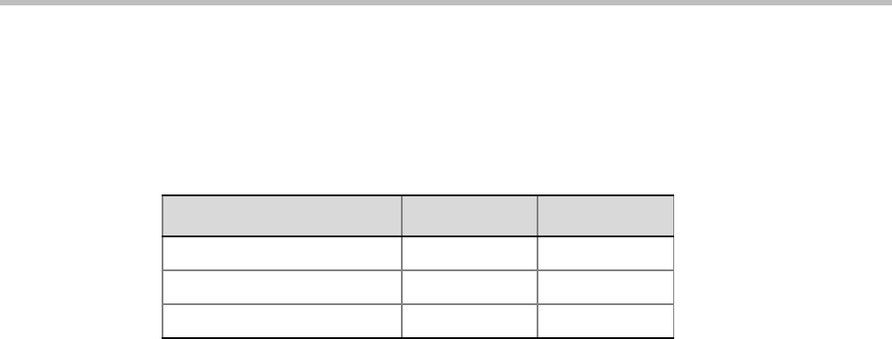
Polycom® RealPresence Collaboration ServerVirtual Edition Administrator’s Guide
19-32 Polycom, Inc.
Audible Alarm Permissions
An operator/administrator can configure the Request Operator Assistance audible alarm,
however Users with different authorization level have different configuration capabilities as
shown in Table 19-20.
Stop Repeating Message
The Collaboration Server User can stop playing the audible alarm at any time. If more than
one audible alarm has been activated, all activated alarms are immediately stopped.
If after stopping the Audible Alarms a new Operator Assistance request event occurs, the
audible alarm is re-activated.
To stop the Audible Alarm on the Collaboration Server Client or RMX Manager:
>> On the Collaboration Server menu, click Setup > Audible Alarms >Stop Repeating
Alarm.
When selected all audible alarms are immediately stopped.
Configuring the Audible Alarms
User Customization
The operators and administrators can:
• Enable/Disable the Audible Alarm.
• Select whether to repeat the Audible Alarm.
• Define the number of repetitions and the interval between the repetitions.
To Customize the Audio Alert on the Collaboration Server Client or RMX Manager:
1On the Collaboration Server menu, click Setup > Audible Alarms > User
Customization.
Table 19-20 Audible Alarm Permissions
Option Operator Administrator
User Customization
Download Audible Alarm File
Stop Repeating Alarms
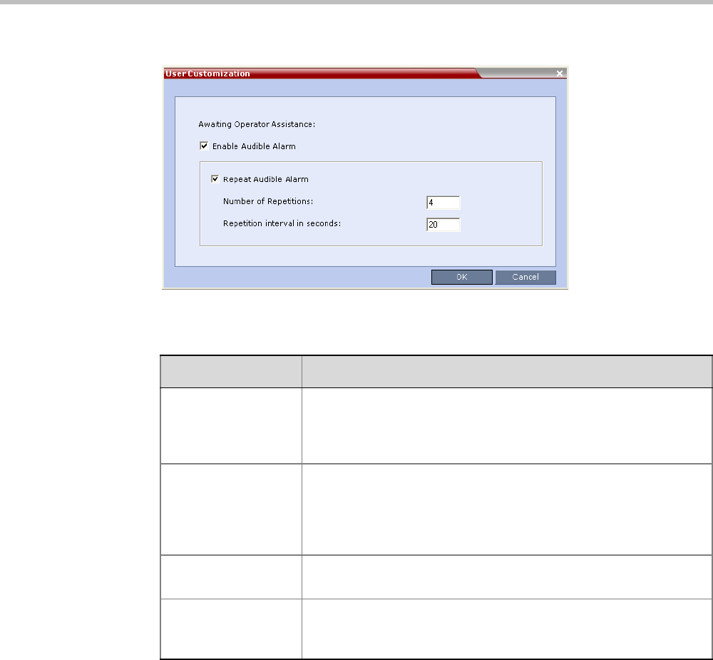
Chapter 19-Collaboration Server Administration and Utilities
Polycom, Inc. 19-33
The User Customization window opens.
2Define the following parameters:
3Click OK.
Replacing the Audible Alarm File
Each Collaboration Server is shipped with a default tone file in *.wav format that plays a
specific tone when participants request Operator Assistance. This file can be replaced by a
*.wav file with your own recording. The file must be in *.wav format and its length cannot
exceed one hour.
Only the User with Administrator permission can download the Audible Alarm file.
Table 19-21 Audible Alarm - User Customization Options
Option Description
Enable Audible Alarm Select this check box to enable the Audible Alarm feature and to
define its properties.
When this check box is cleared, the Audible Alarm functionality is
disabled.
Repeat Audible Alarm Select this check box to play the Audible Alarm repeatedly. When
selected, it enables the definition of the number of repetitions and the
interval between repetitions.
When cleared, the Audible Alarm will not be repeated and will be
played only once.
Number of
Repetitions
Define the number of times the audible alarm will be played.
Default number of repetitions is 4.
Repetition interval in
seconds
Define the number of seconds that the system will wait before playing
the Audible Alarm again.
Default interval is 20 seconds.
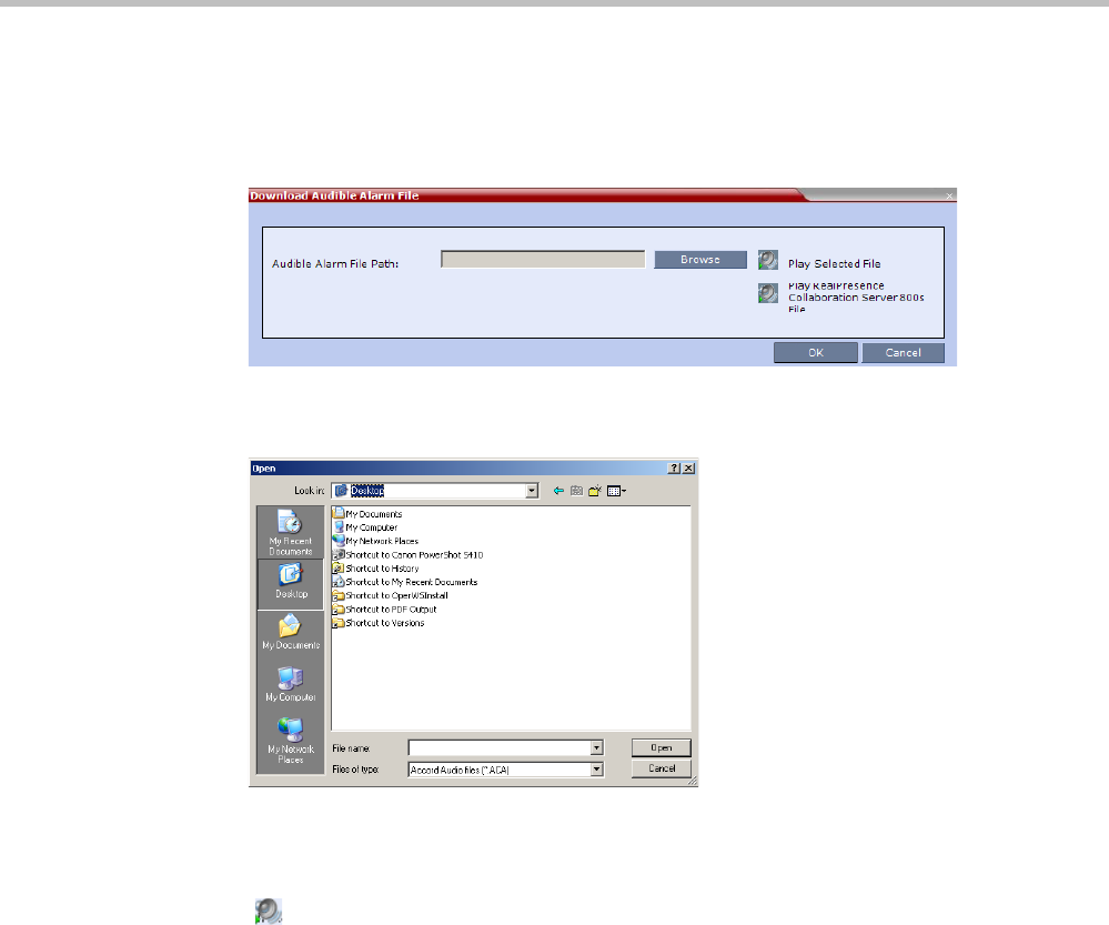
Polycom® RealPresence Collaboration ServerVirtual Edition Administrator’s Guide
19-34 Polycom, Inc.
To replace the Audio file on the Collaboration Server Client or RMX Manager:
1On the Collaboration Server menu, click Setup > Audible Alarms > Download
Audible Alarm File.
The Download Audible Alarm File window opens.
2Click the Browse button to select the audio file (*.wav) to download.
The Open dialog box opens.
3Select the appropriate *.wav file and then click the Open button.
The selected file name is displayed in the Install Audible Alarm File dialog box.
4Optional. You can play the selected file or the currently used file by clicking the Play
() button as follows:
aClick Play Selected File to play a file saved on your computer.
bClick Play Collaboration Server File to play the file currently saved on the
Collaboration Server.
5In the Download Audible Alarm File dialog box, click OK to download the file to the
MCU.
The new file replaces the file stored on the MCU. If multiple Collaboration Servers are
configured in the RMX Manager, the file must be downloaded to each of the required MCUs
separately.
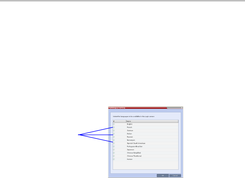
Chapter 19-Collaboration Server Administration and Utilities
Polycom, Inc. 19-35
Multilingual Setting
Each supported language is represented by a country flag in the Welcome Screen and can be
selected as the language for the Collaboration Server Web Client.
Customizing the Multilingual Setting
The languages available for selection in the Login screen of the Collaboration Server Web Client
can be modified using the Multilingual Setting option.
To customize the Multilingual Setting:
1On the Collaboration Server menu, click Setup > Customize Display Settings >
Multilingual Setting.
The Multilingual Setting dialog box is displayed.
2Click the check boxes of the languages to be available for selection.
3Click OK.
4Log out from the Collaboration Server Web Client and Log in for the customization to take
effect.
Selected
Languages
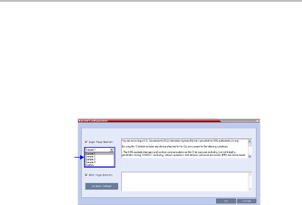
Polycom® RealPresence Collaboration ServerVirtual Edition Administrator’s Guide
19-36 Polycom, Inc.
Banner Display and Customization
The Login Screen and Main Screen of the Collaboration Server Web Client and the Collaboration
Server Manager can display informative or warning text banners. These banners can include
general information or they can be cautioning users to the terms and conditions under
which they may log into and access the system, as required in many secured environments.
Banner display is enabled in the Setup > Customize Display Settings > Banners Configuration.
The administrator can choose one of four alternative login banners to be displayed. The four
alternative banners cannot be modified. A Custom banner (default) can also be defined.
The Main Page Banner is blank and can be defined.
The Banner Configuration dialog box allows the administrator to select a Login Banner from a
drop-down menu.
One of the the following Login Banners can be selected:
•Non-Modifiable Banners
—Sample 1
—Sample 2
—Sample 3
—Sample 4
•Modifiable Banner
—Custom (Default)
Guidelines
•The Login Banner must be acknowledged before the user is permitted to log in to the
system.
•If a Custom banner has been created, and the user selects one of the alternative, non-
modifiable banners the Custom banner not deleted.
•The Custom Login Banner banner may contain up to 1300 characters.
•An empty Login Banner is not allowed.
Login
Banner
Menu

Chapter 19-Collaboration Server Administration and Utilities
Polycom, Inc. 19-37
• Any attempt to modify a non-modifiable banner results in it automatically being copied
to the Custom banner.
Non-Modifiable Banner Text
Sample 1 Banner
You are accessing a U.S. Government (USG) Information System (IS) that is
provided for USG-authorized use only.
By using this IS (which includes any device attached to this IS), you
consent to the following conditions:
− The USG routinely intercepts and monitors communications on this IS for
purposes including, but not limited to, penetration testing, COMSEC
monitoring, network operations and defense, personnel misconduct (PM), law
enforcement (LE), and counterintelligence (CI) investigations.
− At any time, the USG may inspect and seize data stored on this IS.
− Communications using, or data stored on, this IS are not private, are
subject to routine monitoring, interception, and search, and may be
disclosed or used for any USG authorized purpose.
− This IS includes security measures (e.g., authentication and access
controls) to protect USG interests--not for your personal benefit or
privacy.
− Notwithstanding the above, using this IS does not constitute consent to
PM, LE or CI investigative searching or monitoring of the content of
privileged communications, or work product, related to personal
representation or services by attorneys, psychotherapists, or clergy, and
their assistants. Such communications and work product are private and
confidential. See User Agreement for details.
Sample 2 Banner
This system is for the use of authorized users only. Individuals using this
computer system without authority, or in excess of their authority, are
subject to having all of their activities on this system monitored and
recorded by systems personnel. In the course of monitoring individuals
improperly using this system, or in the course of system maintenance, the
activities of authorized users also may be monitored. Anyone using this
system expressly consents to such monitoring and is advised that if such
monitoring reveals possible criminal activity, system personnel may provide
the evidence of such monitoring to law enforcement officials.
Sample 3 Banner
You are about to access a system that is intended for authorized users only.
You should have no expectation of privacy in your use of this system. Use
of this system constitutes consent to monitoring, retrieval, and disclosure
of any information stored within the system for any purpose including
criminal prosecution.
Sample 4 Banner
This computer system including all related equipment, network devices
(specifically including Internet access), is provided only for authorized
use. All computer systems may be monitored for all lawful purposes,
including ensuring that their use is authorized, for management of the
system, to facilitate protection against unauthorized access, and to verify
security procedures, survivability and operational security. Monitoring
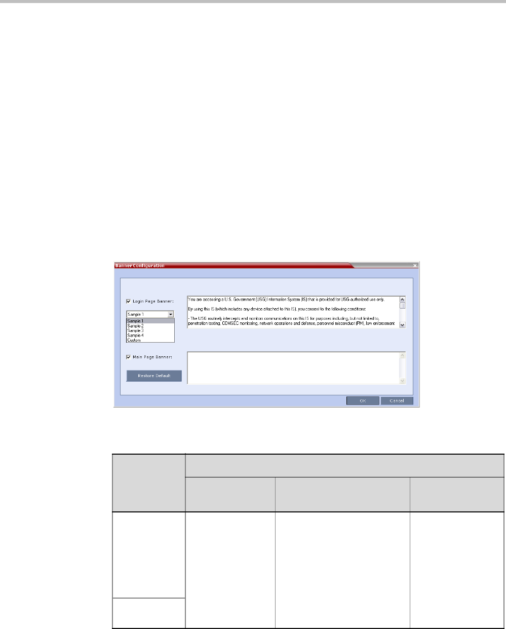
Polycom® RealPresence Collaboration ServerVirtual Edition Administrator’s Guide
19-38 Polycom, Inc.
includes active attacks by authorized personnel and their entities to test
or verify the security of the system. During monitoring, information may be
examined, recorded, copied and used for authorized purposes. All information
including personal information, placed on or sent over this system may be
monitored. Use of this system, authorized or unauthorized, constitutes
consent to monitoring of this system. Unauthorized use may subject you to
criminal prosecution. Evidence of any such unauthorized use collected during
monitoring may be used for administrative, criminal or other adverse action.
Use of this system constitutes consent to monitoring for these purposes.
Customizing Banners
The Login and Main Screen banners can be customized to display conference information,
assistance information or warning text as required in the Ultra Secure Mode.
To customize the banners:
1In the Collaboration Server menu, click Setup > Customize Display Settings > Banners
Configuration.
The Banners Configuration dialog box opens.
2Customize the banners by modifying the following fields:
3Click the OK button.
Table 19-22 Banner Configuration
Field
Description
Check Box Text Field Restore Default
Button
Login Page
Banner
Select or clear the
check box to
enable or disable
the display of the
banner.
Edit the text in this field to
meet local requirements:
•Banner content is
multilingual and uses
Unicode, UTF-8 encoding.
All text and special
characters can be used.
•Maximum banner size is
100KB.
Click the button to
restore the default
text to the banner
Main Page
Banner
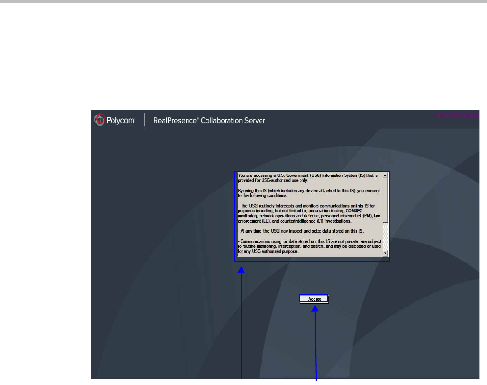
Chapter 19-Collaboration Server Administration and Utilities
Polycom, Inc. 19-39
Banner Display
Login Screen Banner
The Login screen banner can display any text, for example the terms and conditions for
system usage. The user must acknowledge that the information was read and click the
Accept button to proceed to the Login screen as shown in the following screen:
Accept
Button
Terms of Usage
Banner
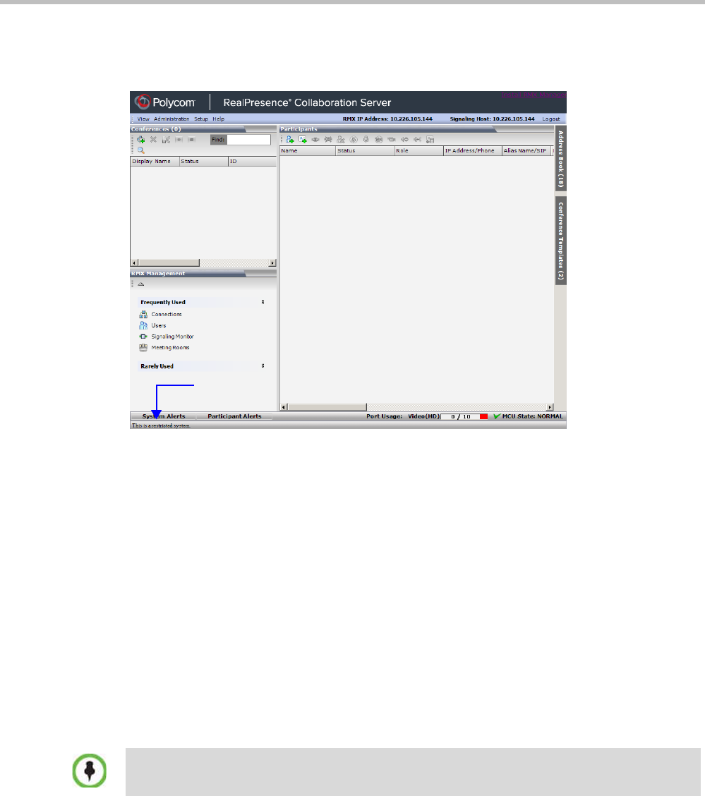
Polycom® RealPresence Collaboration ServerVirtual Edition Administrator’s Guide
19-40 Polycom, Inc.
Main Screen Banner
The Main Screen banner is displayed at the bottom of the screen, as follows:
Software Management
The Software Management menu is used to backup and restore the Collaboration Server's
configuration files and to download MCU software.
Backup and Restore Guidelines
•System Backup can only be performed by an administrator.
•The System Backup procedure creates a single backup file that can be viewed or
modified only by developers.
•A System Backup file from one system can be restored on another system.
• To ensure file system consistency, do not perform any configuration changes as the
system does not suspended them during the backup procedure.
• The following parameters, settings and files are backed up:
—MCMS configuration files (/mcms/Cfg):
—Network and service configurations,
Banner
This applies only to one RealPresence Collaboration Server Virtual Edition system to another. Do
not use a backup file from the RealPresence Collaboration Server Virtual Edition on any other
model.
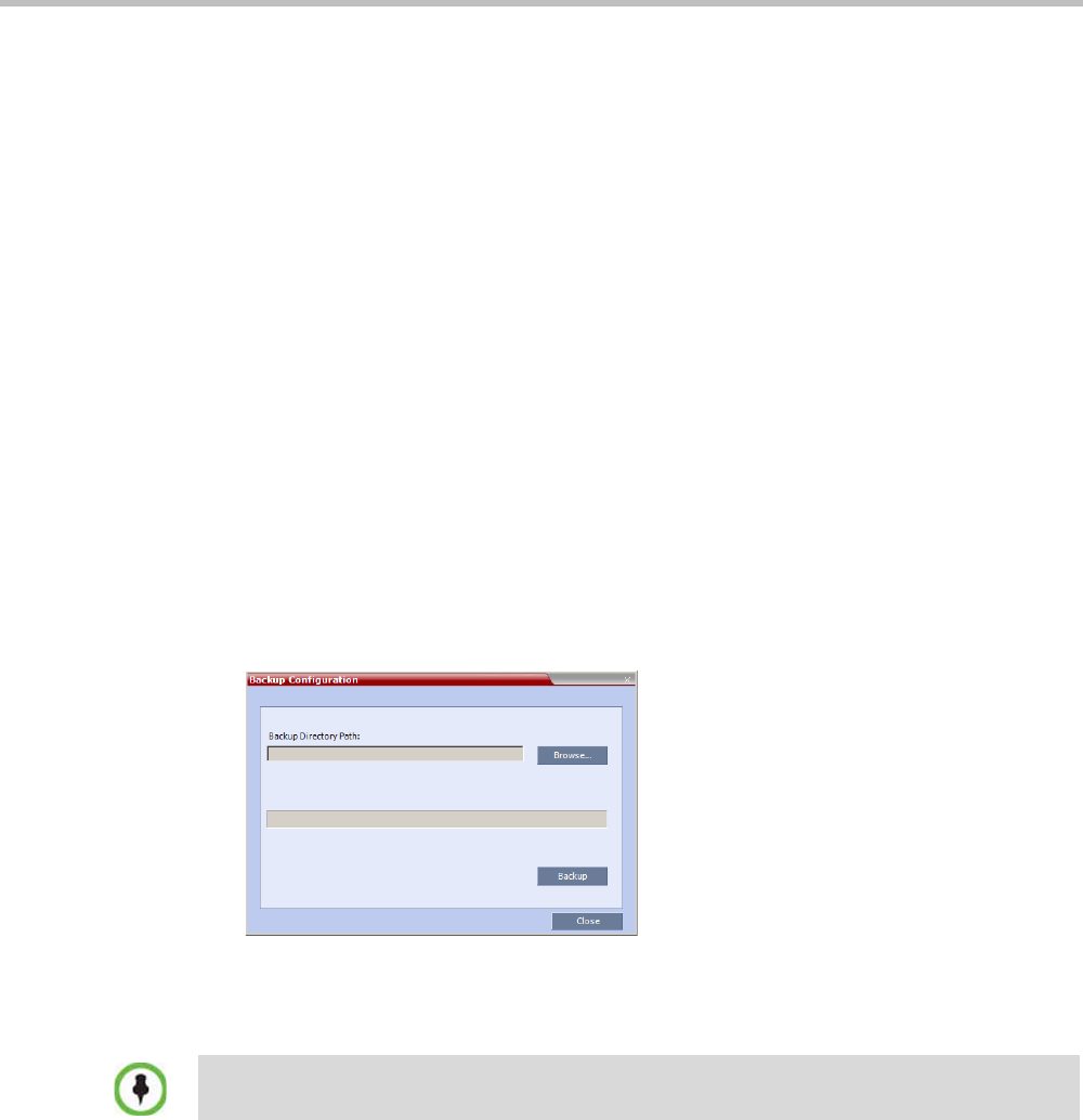
Chapter 19-Collaboration Server Administration and Utilities
Polycom, Inc. 19-41
—Rooms,
—Profiles
—System Flags
—Resource Allocation
—IVR messages, music
—Collaboration Server Web Client user setting - fonts, windows
—Collaboration Server Web Client global settings – notes, address book, language
—Private keys and certificates (TLS)
—Conference participant settings
—Operation DB (administrator list)
—SNMP settings
—Time configuration
• CDR files are not included in the backup process and should be backed up manually by
saving the CDR files to a destination device.
Using Software Management
To backup configuration files:
1On the Collaboration Server menu, click Administration > Software Management >
Backup Configuration.
The Backup Configuration dialog box opens.
2Click the Browse button.
The Browse To File dialog box opens.
3Select the Backup Directory Path and then click Backup.
To restore configuration files:
1On the Collaboration Server menu, click Administration > Software Management >
Restore Configuration.
2Browse to the Restore Directory Path where the backed up configuration files are stored
and then click Restore.
To download MCU software files:
1On the Collaboration Server menu, click Administration > Software Management >
Software Download.
2Browse to the Install Path and then click Install.
When the Collaboration Server system backs up the current configuration, if any changes occur
immediately or during the request, then additional changes are not registered.
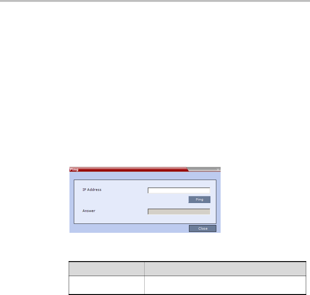
Polycom® RealPresence Collaboration ServerVirtual Edition Administrator’s Guide
19-42 Polycom, Inc.
Ping Collaboration Server
The Ping administration tool enables the Collaboration Server Signaling Host to test network
connectivity by Pinging IP addresses.
Guidelines
• Both explicit IP addresses and Host Names are supported.
•The Collaboration Server Web Client blocks any attempt to issue another Ping command
before the current Ping command has completed. Multiple Ping commands issued
simultaneously from multiple Collaboration Server Web Clients are also blocked.
Using Ping
To Ping a network entity from the Collaboration Server:
1On the Collaboration Server menu, click Administration > Tools > Ping.
The Ping dialog box is displayed:
2Modify or complete the following field:
3Click the Ping button.
The Ping request is sent to the Host Name or IP Address of the Collaboration Server entity.
The Answer is either:
—OK, or
—FAILED
Notification Settings
The Collaboration Server can display notifications when:
• A new Collaboration Server user connects to the MCU.
• A new conference is started.
Table 19-23 Ping
Field Description
Host Name or Address Enter the Host Name or IP Address of the network entity to be
Pinged.
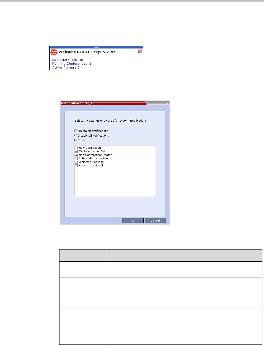
Chapter 19-Collaboration Server Administration and Utilities
Polycom, Inc. 19-43
• Not all defined participants are connected to the conference or when a single
participant is connected.
• A change in the MCU status occurs and an alarm is added to the alarm’s list.
A welcome message is displayed to the Collaboration Server user upon connection.
To configure the notifications:
1On the Collaboration Server menu, select Setup > Notification Settings.
The Notification Settings dialog box is displayed.
The following notification options are displayed.
Table 19-24 Notification Settings Parameters
Field Description
New Connection Notification of a new user/administrator connecting to the
Collaboration Server.
New Conference
Created
New conference has been created.
Conference Not Full The conference is not full and additional participants are defined for
the conference.
Welcome Message A welcome message after user/administrator logon.
Active Alarms Update Updates you of any new alarm that occurred.
Fault List Updated Updates you when the faults list is updated (new faults are added or
existing faults are removed).
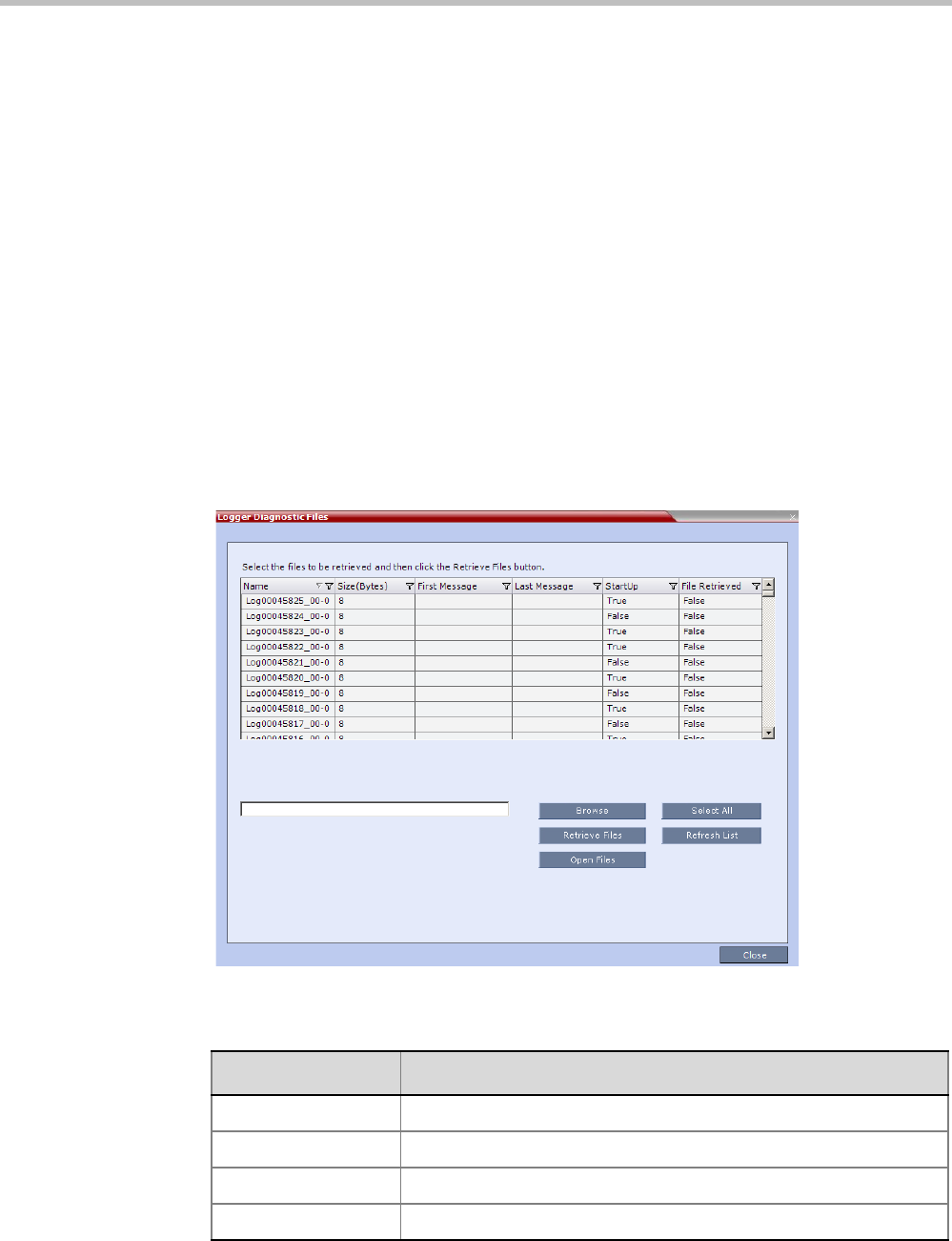
Polycom® RealPresence Collaboration ServerVirtual Edition Administrator’s Guide
19-44 Polycom, Inc.
2Enable/Disable All Notifications or Custom to select specific notifications to display.
3Click OK.
Logger Diagnostic Files
The Logger utility is a troubleshooting tool that continually records MCU system messages
and saves them to files in the MCU hard drive. For each time interval defined in the system,
a different data file is created. The files may be retrieved from the hard drive for off-line
analysis and debugging purposes.
The Logger utility is activated at the MCU startup. The Logger is disabled when the MCU is
reset manually or when there is a problem with the Logger utility, e.g. errors on the hard
drive where files are saved. In such cases, data cannot be retrieved.
When the MCU is reset via the Collaboration Server, the files are saved on the MCU hard
drive.
To access the Logger Diagnostic Files:
>> On the Collaboration Server menu, click Administration > Tools > Logger Diagnostic
Files.
The following tasks can be performed:
Table 19-25 Diagnostic File Button Options
Button Description
Refresh List Refreshes the list and adds newly generated logger files.
Select All Selects all the logger files listed.
Browse Selects the destination folder for download.
Retrieve Files Saves files to the destination folder.
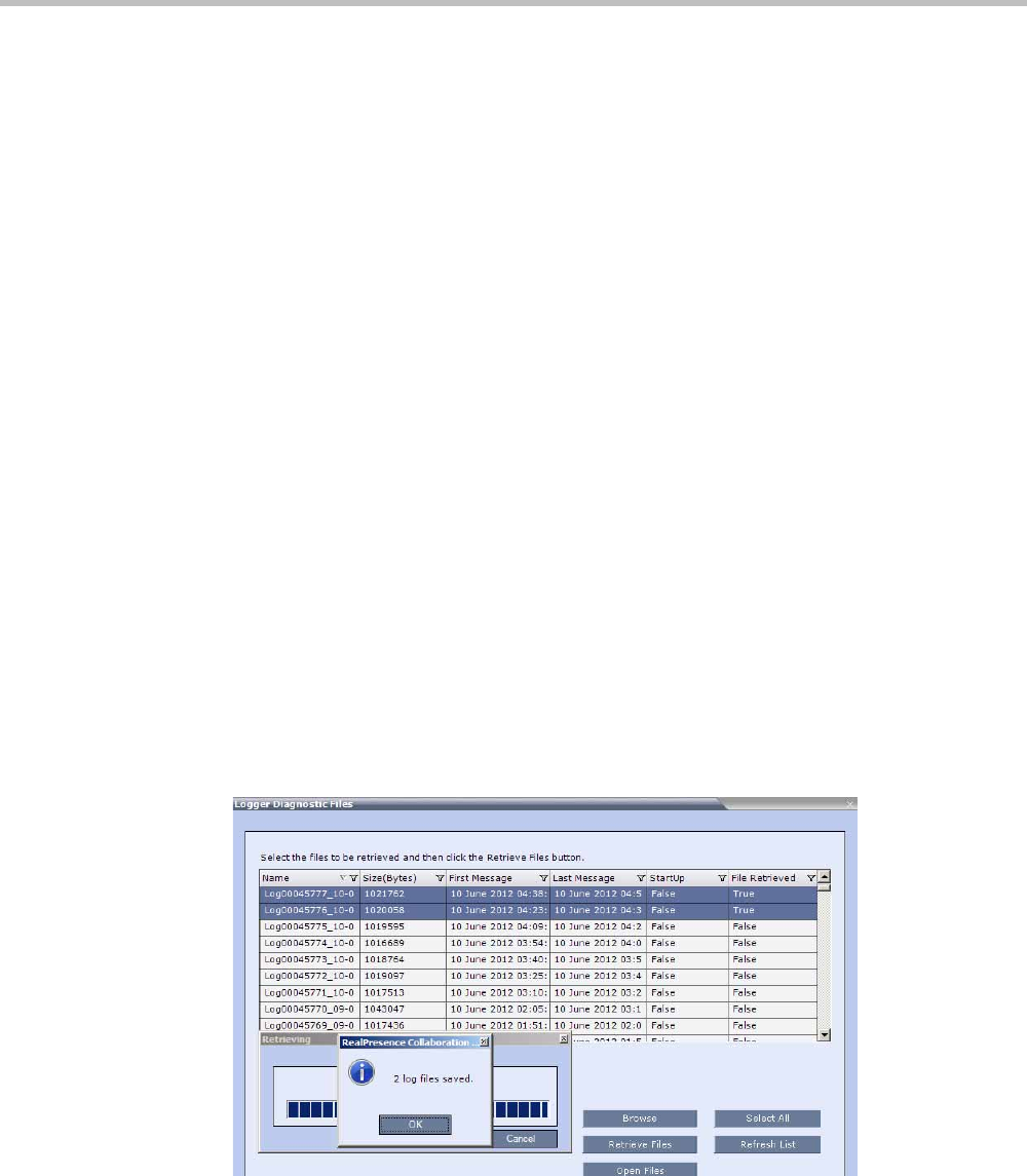
Chapter 19-Collaboration Server Administration and Utilities
Polycom, Inc. 19-45
When retrieved, the log file name structure is as follows:
• Sequence number (starting with 1)
• Date and Time of first message
• Date and Time of last message
•File size
• Special information about the data, such as Startup
File name structure:
Log_SNxxxxxxxxxx_FMDddmmyyy_FMThhmm_LMDddmmyyyy_LMThhmm_SZxxxxxxxxxx_SUY.log
File name format:
• SN = Sequence Number
• FM = First Message, date and time
• LM = Last Message, date and time
•SZ = Size
• SU = Startup (Y/N) during the log file duration
Example:
Log_SN0000000002_FMD06032007_FMT083933_LMD06032007_LMT084356_SZ184951_SUY.log.
Retrieving the Logger Files:
1Select the log files to retrieve. Multiple selections of files are enabled using standard
Windows conventions.
2In the Logger Diagnostic Files dialog box, click the Browse button.
3In the Browse for Folder window, select the directory location to save the Logger files and
click OK.
You will return to the Logger Diagnostic Files dialog box.
4Click the Retrieve Files button.
The log files (in *.txt format) are saved to the defined directory and a confirmation
caption box is displayed indicating a successful retrieval of the log files.

Polycom® RealPresence Collaboration ServerVirtual Edition Administrator’s Guide
19-46 Polycom, Inc.
Viewing the Logger Files:
To analyze the log files generated by the system, open the retrieved *.txt files in any text
editor application, i.e. Notepad, Textpad or MS Word.
1Using Windows Explorer, browse to the directory containing the retrieved log files.
2Use any text editor application to open the log file(s).
Information Collector
Standard Security Mode
The Information Collector comprehensively attains all information from all the MCU
internal entities for data analysis. That data, stored in a central repository, is logged from the
following system components:
The data collected is saved into a single compressed file containing all the information from
each system component in its relative format (.txt, .xml, etc...). In case the disk is
malfunctioning, the file will be written to the RAM (involves only a small amount of
information where the RAM size is 1/2 a gigabyte). The zipped file (info.tgz) can be opened
with the following applications: WinRAR and WinZip. The entire zipped file is then sent to
Polycom’s Network Systems Division for analysis and troubleshooting.
Using the Information Collector
When the Information Collector is used the following steps are performed:
•Step 1: Creating the Information Collector file.
•Step 2: Saving the Information Collector file.
•Step 3: Viewing the information in the Information Collector file.
• System Log Files • Full faults
•CDR •Apache logs
• OS (Core dumps, CFG - DNS, DHCP,
NTP, kernal state, event logs
• CFG directory (without IVR)
• Signaling Trace files (H.323 & SIP) • Cards info: HW version, state and status
• Central Signaling logs • SW version number
• Processes internal state and statistics
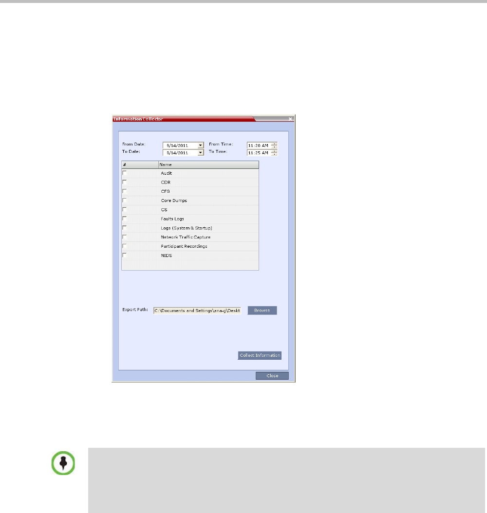
Chapter 19-Collaboration Server Administration and Utilities
Polycom, Inc. 19-47
Step 1: Creating the Information Collector Compressed File
To create the compressed file:
1In the Collaboration Server menu, click Administration > Tools > Information
Collector.
The Information Collector dialog box is displayed.
2In the From Date and Until Date fields, use the arrow keys to define the date range of the
data files to be included in the compressed file.
3In the From Time and Until Time fields, use the arrow keys to define the time range of
the data files to be included in the compressed file.
4Select check boxes of the information to be collected.
5In the Export Path field, click the Browse button and navigate to the directory path
where the compressed file is to be saved.
6Click the Collect Information button.
A progress indicator is displayed in the Information Collector dialog box while the file is
being created.
Standard Security Mode
If logs are being collected in order to troubleshoot a specific issue, it is important that the date and
time range include the time and date in which the issue occurred. The default date and time ranges
may not be sufficient.
For example, if a specific issue occurred on October 1, 2013 at 12:15, the From Date and Until Date
should be October 1, 2013, the From Time should be around 12:10, and the Until Time should be
around 12:20.

Polycom® RealPresence Collaboration ServerVirtual Edition Administrator’s Guide
19-48 Polycom, Inc.
Step 2: Saving the Compressed File
1The compressed file is automatically saved in the directory selected in the Information
Collector dialog box. The file is named info.tgz.
A success information box is displayed.
2Click the OK button.
Step 3: Viewing the Compressed File
The compressed file is saved in .tgz format and can be viewed with any utility that can open
files of that format, for example WinRAR® 3.80.
To view the compressed file:
1Navigate to the directory on the workstation in which the file was saved.
2Double click the info.tgz file to view the downloaded information.
Auditor
An Auditor is a user who can view Auditor and CDR files for system auditing purposes.
The Event Auditor enables administrators and auditors to analyze configuration changes and
unusual or malicious activities in the Collaboration Server system.
Auditor operates in real time, recording all administration activities and login attempts from
the following Collaboration Server modules:
• Control Unit
• Shelf Manager
For a full list of monitored activities, see Table 19-27 on page 19-52 and Table 19-28 on
page 19-54.
The Auditor must always be active in the system. A System Alert is displayed if it becomes
inactive for any reason.
The Auditor tool is composed of the Auditor Files and the Auditor File Viewer that enables you
to view the Auditor Files.
Auditor Files
Auditor Event History File Storage
All audit events are saved to a buffer file on hard disk in real time and then written to a file
on hard disk in XML in an uncompressed format.
Some browsers save the file as info.gz due to a browser bug. If this occurs, the file must be
manually renamed to info.tgz before it can be viewed.
The Auditor user must connect to the Collaboration Server using the Collaboration Server Web
Client only.
Time stamps of Audit Events are GMT.
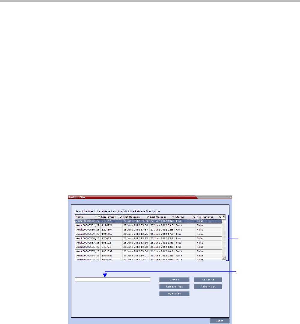
Chapter 19-Collaboration Server Administration and Utilities
Polycom, Inc. 19-49
A new current auditor event file is created when:
• the system is started
• the size of the current auditor event file exceeds 2 MB
• the current auditor event file’s age exceeds 24 hours
Up to 1000 auditor event files are stored per Collaboration Server. These files are retained for
at least one year and require 1.05 GB of disk space. The files are automatically deleted by the
system (oldest first) when the system reaches the auditor event file limit of 1000.
A System Alert is displayed with Can't store data displayed in its Description field if:
• the system cannot store 1000 files
•the Collaboration Server does not have available disk space to retain files for one year
Audit Event Files are retained by the Collaboration Server for at least 1 year. Any attempt to
delete an audit event file that is less than one year old raises a System Alert with File was
removed listed in the Description field.
Using the Restore Factory Defaults of the System Restore procedure erases Audit Files.
Retrieving Auditor Files
You can open the Auditor file directly from the Auditor Files list or you can retrieve the files
and save them to a local workstation.
To access Auditor Files:
>> On the Collaboration Server menu, click Administration > Tools > Auditor Files.
The Auditor Files dialog box is displayed.
The Auditor Files dialogue box displays a file list containing the following file
information:
—Name
—Size (Bytes)
—First Message – date and time of the first audit event in the file
—Last Message – date and time of the last audit event in the file
—StartUp:
•True – file was created when the system was started
File List
Directory
Path
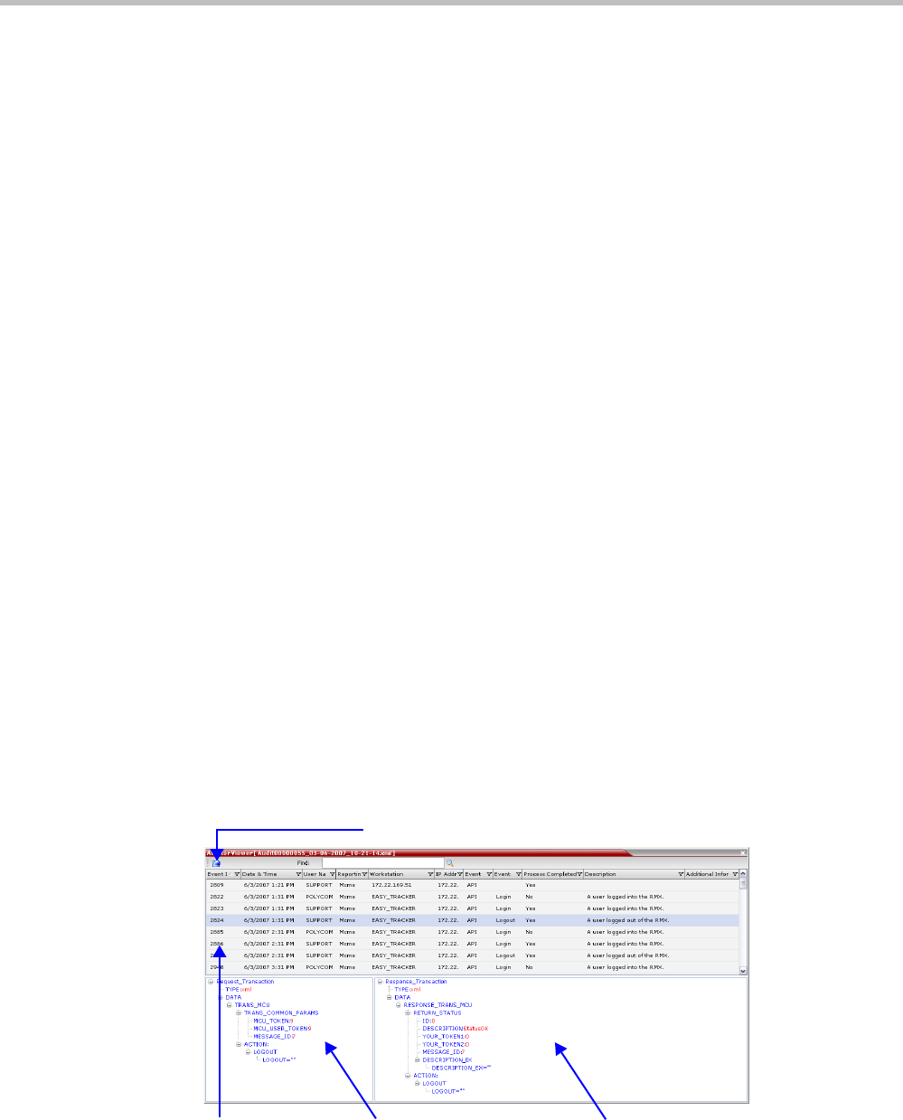
Polycom® RealPresence Collaboration ServerVirtual Edition Administrator’s Guide
19-50 Polycom, Inc.
•False – file was created when previous audit event file reached a size of 2 MB
or was more than 24 hours old
—File Retrieved:
•True - file was previously retrieved.
•False - file was never previously retrieved.
The order of the Auditor Files dialog box field header columns can be changed and the
fields can be filtered to enable searching.
For more information, see "Auditor File Viewer” on page 19-50.
To retrieve files for storage on a workstation:
1Click Browse and select the folder on the workstation to receive the files and then click
OK.
The folder name is displayed in the directory path field.
2Select the file(s) to be retrieved by clicking their names in the file list or click Select All
to retrieve all the files. (Windows multiple selection techniques can be used.)
3Click Retrieve Files.
The selected files are copied to the selected directory on the workstation.
To open the file in the Auditor File Viewer:
>> Double-click the file.
Auditor File Viewer
The Auditor File Viewer enables Auditors and Administrators to view the content of and
perform detailed analysis on auditor event data in a selected Auditor Event File.
You can view an Auditor Event File directly from the Auditor Files list or by opening the file
from the Auditor File Viewer.
To open the Auditor File Viewer from the Administration Menu:
1On the Collaboration Server menu, click Administration > Tools > Auditor File Viewer.
The Auditor File Viewer is displayed.
If you previously double clicked an Auditor Event File in the Auditor Files list, that file is
automatically opened.
Event
List (ID)
Response Transaction
Tree
Request Transaction
Tree
Local File

Chapter 19-Collaboration Server Administration and Utilities
Polycom, Inc. 19-51
The following fields are displayed for each event:
Table 19-26 Auditor Event Columns
Field Description
Event ID The sequence number of the event generated by the Collaboration
Server.
Date & Time The date and time of the event taken from the Collaboration Server’s
Local Time setting.
User Name The Username (Login Name) of the user who triggered the event.
Reporting Module The Collaboration Server system internal module that reported the
event:
•MCMS
•MPL
•Central Signaling
•MPL Simulation
•Collaboration Server Web Client
•CM Switch
•ART
•Video
•MUX
Workstation The name (alias) of the workstation used to send the request that
triggered the event.
IP Address
(Workstation)
The IP address of the workstation used to send the request that
triggered the event.
Event Type Auditor events can be triggered by:
•API
•HTTP
•Collaboration Server Internal Event
Event The process, action, request or transaction that was performed or
rejected.
•POST:SET transactions (API)
•Configuration changes via XML (API)
•Login/Logout (API)
•GET (HTTP)
•PUT (HTTP)
•MKDIR (HTTP)
•RMDIR (HTTP)
•Startup (Collaboration Server Internal Event)
•Shutdown (Collaboration Server Internal Event)
•Reset (Collaboration Server Internal Event)
•Enter Diagnostic Mode (Collaboration Server Internal Event)
•IP address changes via USB (Collaboration Server Internal Event)

Polycom® RealPresence Collaboration ServerVirtual Edition Administrator’s Guide
19-52 Polycom, Inc.
The order of the Auditor File Viewer field header columns can be changed and the fields
can be sorted and filtered to facilitate different analysis methods.
2In the event list, click the events or use the keyboard’s Up-arrow and Down-arrow keys
to display the Request Transaction and Response Transaction XML trees for each audit
event.
The transaction XML trees can be expanded and collapsed by clicking the expand
( ) and collapse ( ) buttons.
To open an auditor event file stored on the workstation:
1Click the Local File button ( ) to open the Open dialogue box.
2Navigate to the folder on the workstation that contains the audit event file.
3Select the audit event file to be opened.
4Click Open.
The selected file is opened in the Auditor Viewer.
Audit Events
Alerts and Faults
Table 1 lists Alerts and Faults that are recorded by the Auditor.
Process Completed Status of the process, action, request or transaction returned by the
system:
•Yes – performed by the system.
•No – rejected by the system.
Description A text string describing the process, action, request or transaction.
Additional Information An optional text string describing the process, action, request or
transaction in additional detail.
Table 19-26 Auditor Event Columns (Continued)
Field Description
Table 19-27 Alerts and Faults
Event
Attempt to exceed the maximum number of management session per user
Attempt to exceed the maximum number of management sessions per
system
Central Signaling indicating Recovery status.
Failed login attempt
Failed to open Apache server configuration file.
Failed to save Apache server configuration file.
Fallback version is being used.

Chapter 19-Collaboration Server Administration and Utilities
Polycom, Inc. 19-53
File system scan failure.
File system space shortage.
Internal MCU reset.
Internal System configuration during startup.
Invalid date and time.
Invalid MCU Version.
IP addresses of Signaling Host and Control Unit are the same.
IP Network Service configuration modified.
IP Network Service deleted.
Login
Logout
Management Session Time Out
MCU Reset to enable Diagnostics mode.
MCU reset.
Music file error.
New activation key was loaded.
New version was installed.
NTP synchronization failure.
Polycom default User exists.
Private version is loaded.
Restoring Factory Defaults.
Secured SIP communication failed.
Session disconnected without logout
SSH is enabled.
System Configuration modified.
System is starting.
System Resets.
TCP disconnection
Terminal initiated MCU reset.
The Log file system is disabled.
The software contains patch(es).
Table 19-27 Alerts and Faults (Continued)
Event

Polycom® RealPresence Collaboration ServerVirtual Edition Administrator’s Guide
19-54 Polycom, Inc.
Transactions
Table 2 lists Transactions that are recorded by the Auditor.
USB key used to change system configuration.
User closed the browser
User initiated MCU reset.
Table 19-28 Transactions
Transaction
TRANS_CFG:SET_CFG
TRANS_IP_SERVICE:DEL_IP_SERVICE
TRANS_IP_SERVICE:NEW_IP_SERVICE
TRANS_IP_SERVICE:SET_DEFAULT_H323_SERVICE
TRANS_IP_SERVICE:SET_DEFAULT_SIP_SERVICE
TRANS_IP_SERVICE:UPDATE_IP_SERVICE
TRANS_IP_SERVICE:UPDATE_MANAGEMENT_NETWORK
TRANS_MCU:BEGIN_RECEIVING_VERSION
TRANS_MCU:COLLECT_INFO
TRANS_MCU:CREATE_DIRECTORY
TRANS_MCU:FINISHED_TRANSFER_VERSION
TRANS_MCU:LOGIN
TRANS_MCU:LOGOUT
TRANS_MCU:REMOVE_DIRECTORY
TRANS_MCU:REMOVE_DIRECTORY_CONTENT
TRANS_MCU:RENAME
TRANS_MCU:RESET
TRANS_MCU:SET_PORT_CONFIGURATION
TRANS_MCU:SET_RESTORE_TYPE
TRANS_MCU:SET_TIME
TRANS_MCU:TURN_SSH
TRANS_MCU:UPDATE_KEY_CODE
TRANS_OPERATOR:CHANGE_PASSWORD
Table 19-27 Alerts and Faults (Continued)
Event
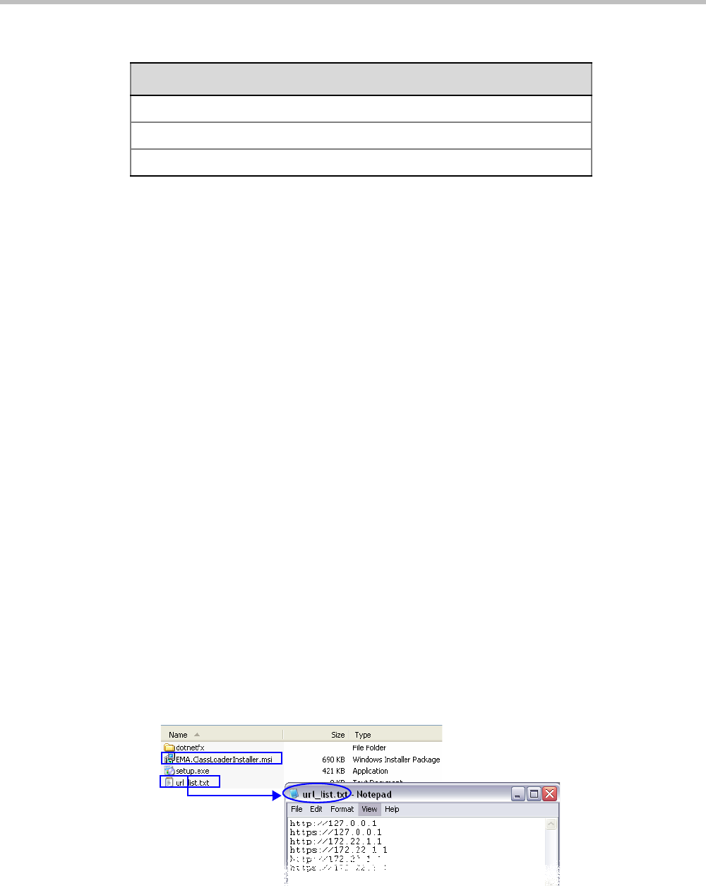
Chapter 19-Collaboration Server Administration and Utilities
Polycom, Inc. 19-55
ActiveX Bypass
At sites that, for security reasons, do not permit Microsoft® ActiveX® to be installed, the
MSI (Windows Installer File) utility can be used to install .NET Framework and .NET
Security Settings components on workstations throughout the network.
All workstation that connect to Collaboration Server systems must have both.NET Framework
and .NET Security Settings running locally. These components are used for communication
with the Collaboration Server and can only be installed on workstations by users with
administrator privileges.
The MSI utility requires the IP addresses of all the Collaboration Server systems (both
control unit and Shelf Management IP addresses) that each workstation is to connect to.
If the IP address of the any of the target Collaboration Servers is changed, the ActiveX
components must be reinstalled.
Installing ActiveX
To install ActiveX components on all workstations in the network:
1Download the MSI file EMA.ClassLoaderInstaller.msi from the Polycom Resource
Center.
The MSI file contains installation scripts for both .NET Framework and .NET Security
Settings.
2Create a text file to be used during the installation containing the IP addresses of all the
Collaboration Server systems (both control unit and Shelf Management IP addresses)
that each workstation in the network is to connect to.
The file must be named url_list.txt and must be saved in the same folder as the
downloaded MSI file.
3Install the ActiveX components on all workstations on the network that connect to
Collaboration Server systems.
TRANS_OPERATOR:DELETE_OPERATOR
TRANS_OPERATOR:NEW_OPERATOR
TRANS_SNMP:UPDATE
Table 19-28 Transactions (Continued)
Transaction

Polycom® RealPresence Collaboration ServerVirtual Edition Administrator’s Guide
19-56 Polycom, Inc.
The installation is done by the network administrator using a 3rd party network
software installation utility and is transparent to all other users.
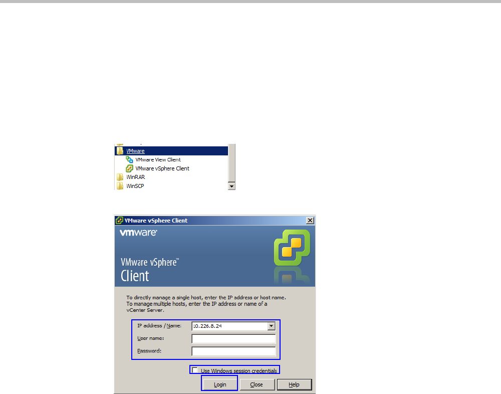
Chapter 19-Collaboration Server Administration and Utilities
Polycom, Inc. 19-57
Resetting the Collaboration Server
To restart the MCU instance:
1Click Start > Programs.
aIf the VMware vSphere Client is displayed in the recently used programs list, click
VMware vSphere Client in the list to start the application.
or
bClick All Programs > VMware > VMware vSphere Client.
The VMware vSphere Client login window opens.
2In the IP address / Name field, enter the IP Address or the name of the vSphere host.
3Enter the User Name and password by either:
aIn the User name field, enter the user name of the with which you will log in to the
vSphere host.
In the Password field, enter the password as defined for the user name with which
you will log in to the vSphere host.
or
bClick the Use Windows session credentials check box.
4Click Login.
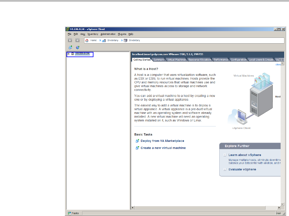
Polycom® RealPresence Collaboration ServerVirtual Edition Administrator’s Guide
19-58 Polycom, Inc.
The VMware vSphere Client opens.
5In the Inventory Panel, click the Datastore that houses the MCU.
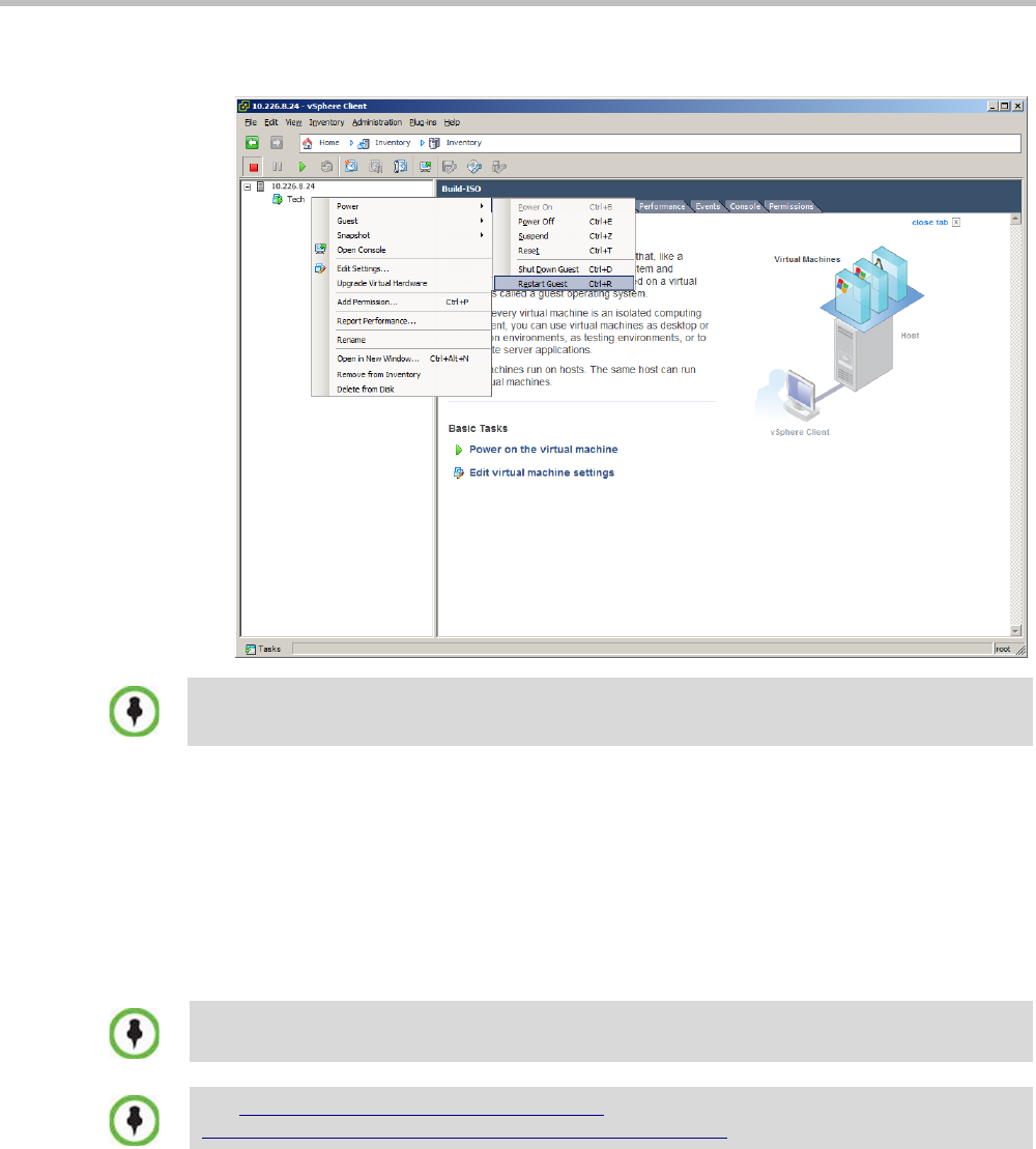
Chapter 19-Collaboration Server Administration and Utilities
Polycom, Inc. 19-59
6Right-click on the MCU virtual machine, then click Power > Restart Guest
The virtual machine and the MCU instance restart.
Upgrading and Downgrading
This procedure allows an administrator to update the MCU instance without requiring the
administrator to reregister the product.
To update the MCU instance:
1On the RealPresence Collaboration Server menu, click Administration > Software
Management > Backup Configuration.
DO NOT click Reset. Doing so may corrupt the Virtual Machine.
Updating the MCU instance requires the previously used activation key. If you no longer have the
activation key, contact support before starting this procedure.
See http://kb.vmware.com/selfservice/microsites/
search.do?language=en_US&cmd=displayKC&externalId=1714 before proceeding.
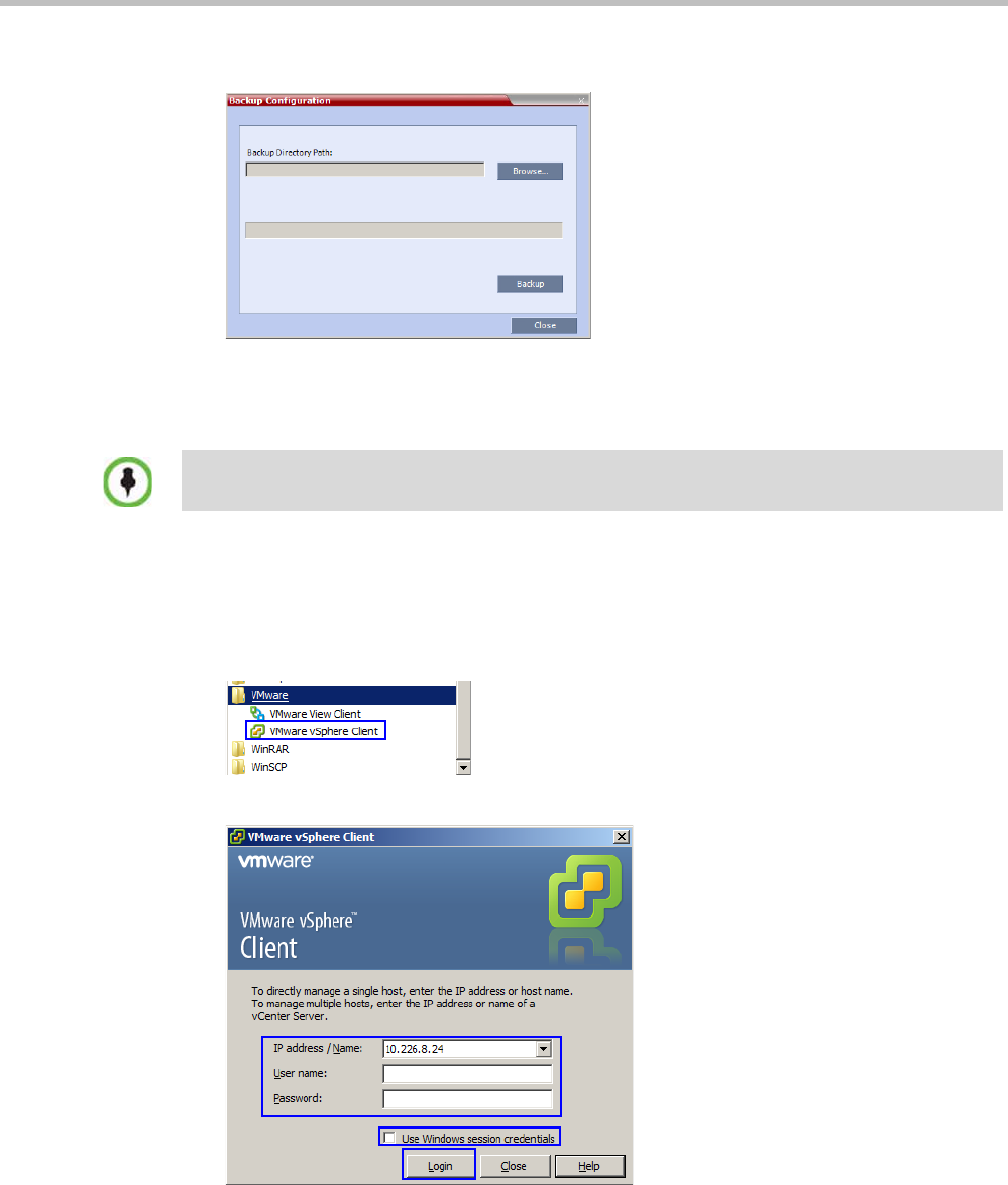
Polycom® RealPresence Collaboration ServerVirtual Edition Administrator’s Guide
19-60 Polycom, Inc.
The Backup Configuration dialog box opens.
2Click the Browse button.
The Browse To File dialog box opens.
3Select the Backup Directory Path and then click Backup.
4On the Windows taskbar, click the Start > Programs.
aIf the VMware vSphere Client is displayed in the recently used programs list, click
VMware vSphere Client in the list to start the application.
or
bSelect All Programs > VMware > VMware vSphere Client.
The VMware vSphere Client login window is displayed.
5In the IP address / Name field, enter the IP Address or the name of the vSphere host.
6Either type your vSphere User Name and Password or select Use Windows sessions
credentials.
7Click Login.
When the RealPresence Collaboration Server backs up the current configuration, if any changes
occur immediately or during the request, then additional changes are not registered.
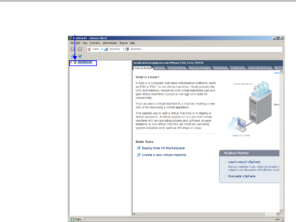
Chapter 19-Collaboration Server Administration and Utilities
Polycom, Inc. 19-61
The VMware vSphere Client is displayed.
8In the Inventory Panel, select the Datastore that houses the MCU.
Inventory Panel

Polycom® RealPresence Collaboration ServerVirtual Edition Administrator’s Guide
19-62 Polycom, Inc.
The inventory of the Datastore appears.
9Right-click the MCU virtual machine, then click Power > Shut Down Guest.
When VM turns blue, the virtual machine has shut down.
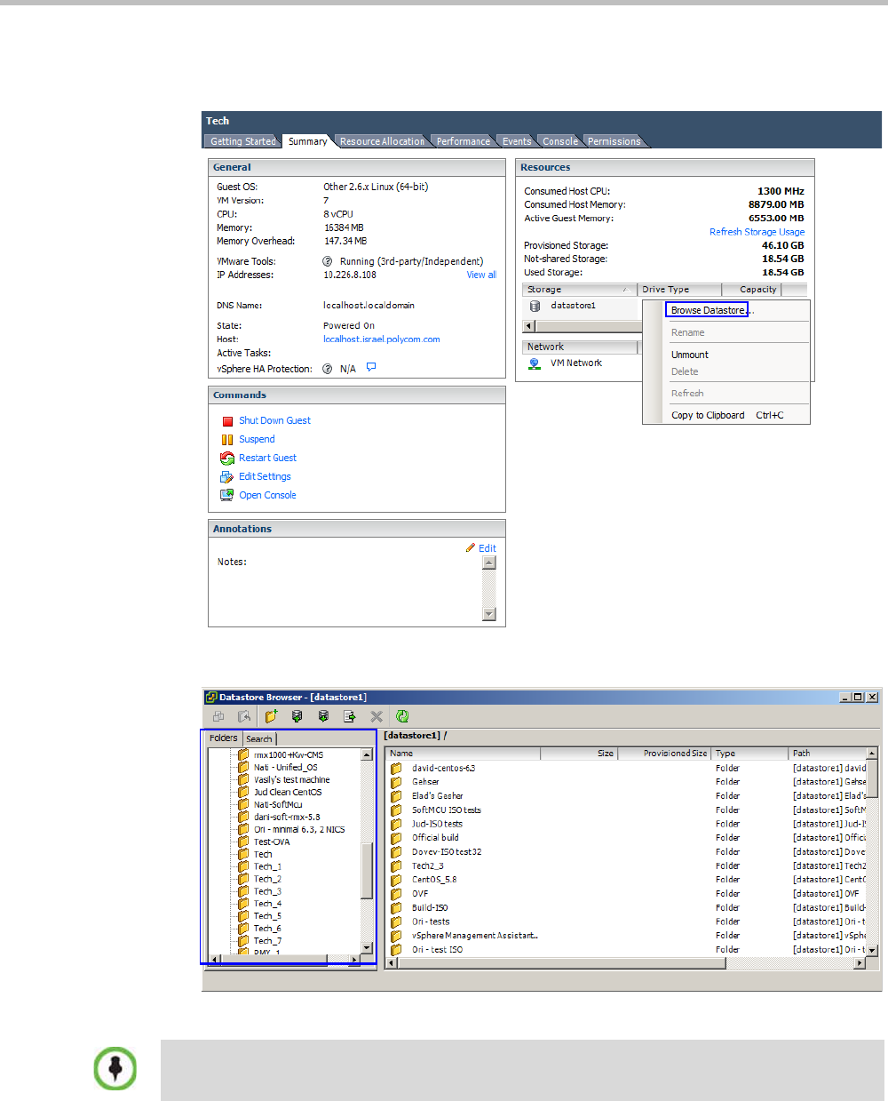
Chapter 19-Collaboration Server Administration and Utilities
Polycom, Inc. 19-63
10 When the MCU has shut down, click the Summary tab.
11 Under Resources, right-click the datastore, and click Browse Datastore.
The Browse Datastore window appears.
12 In the Folders tab, select the folder whose name matches that of the MCU.
If the same name has been used multiple times, there will be multiple folders with an underscore
and a number appended to the name. In such a case, select the folder with the name of the MCU
which ends with the highest number.
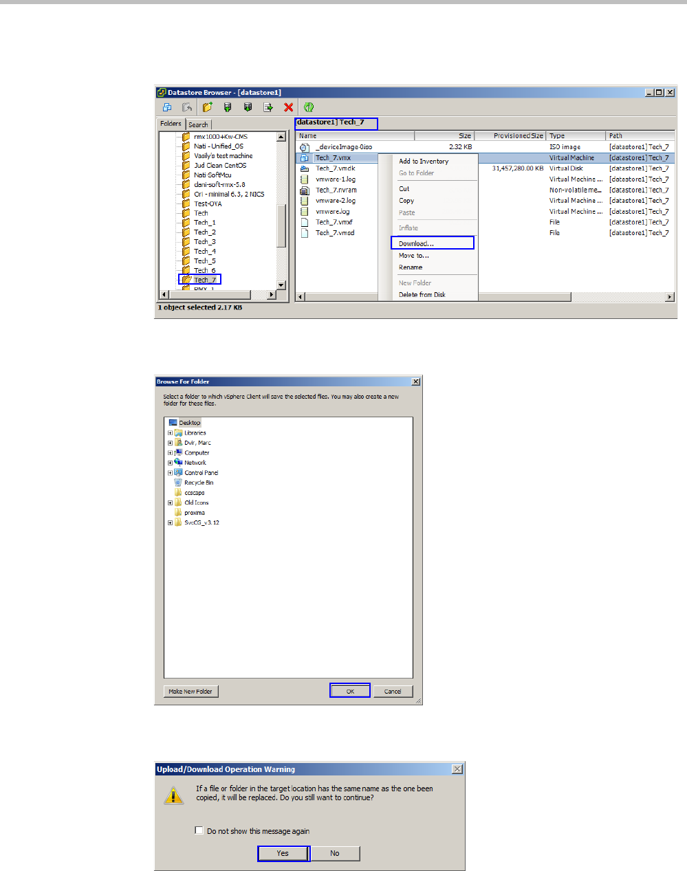
Polycom® RealPresence Collaboration ServerVirtual Edition Administrator’s Guide
19-64 Polycom, Inc.
The contents of the folder are displayed.
13 Right-click the file ending with “.vmx” and click Download.
The Browse For Folder window appears.
14 Browse to a location and click OK.
The Upload/Download Operation Warning window may appear.
15 If the Upload/Download Operation Warning window appears, click Yes.
If it does not appear, proceed to Step 16.
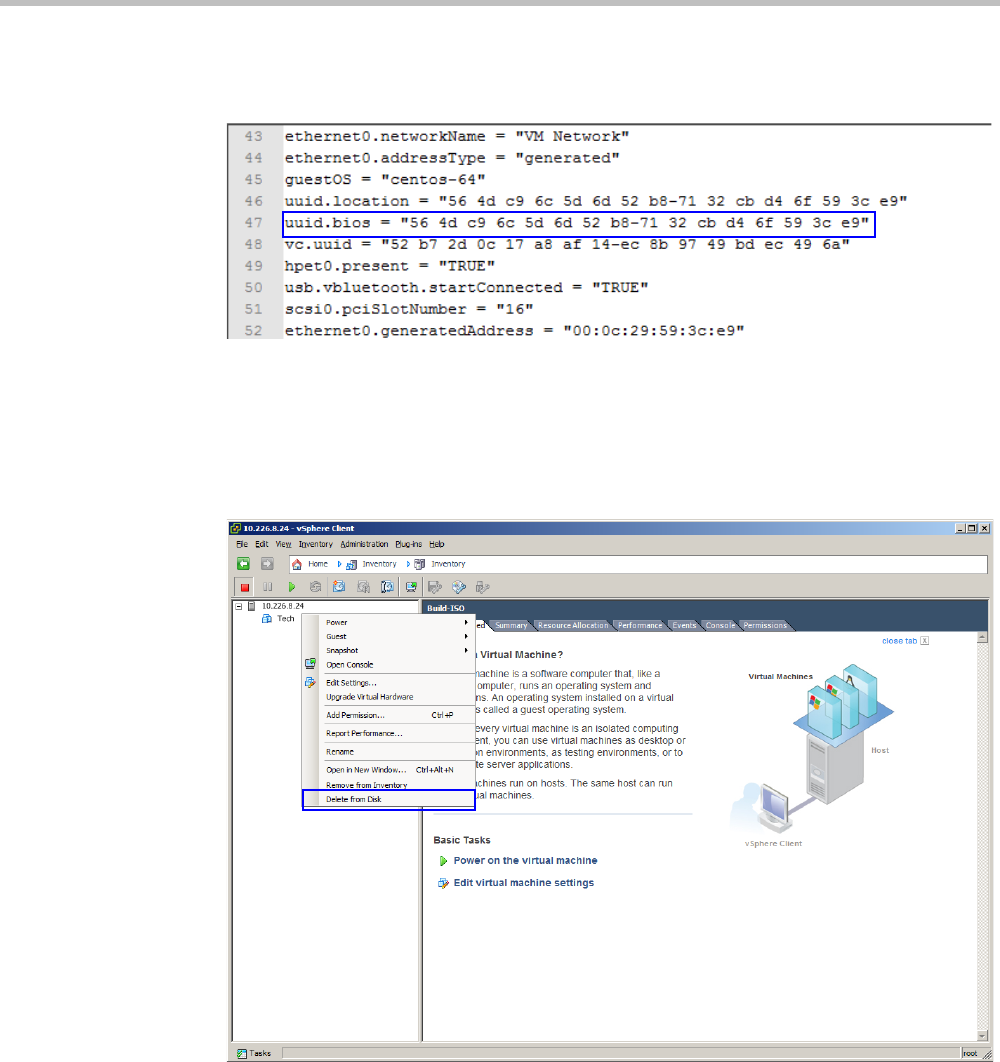
Chapter 19-Collaboration Server Administration and Utilities
Polycom, Inc. 19-65
The file downloads.
16 Open the file in any plain text editor.
17 Locate the line that starts with uuid.bios.
18 Copy the entire line and paste it into another text file.
19 Save the text file.
20 In the Inventory Panel, click the Datastore that houses the MCU.
21 Right-click the MCU, and select Delete from Disk.
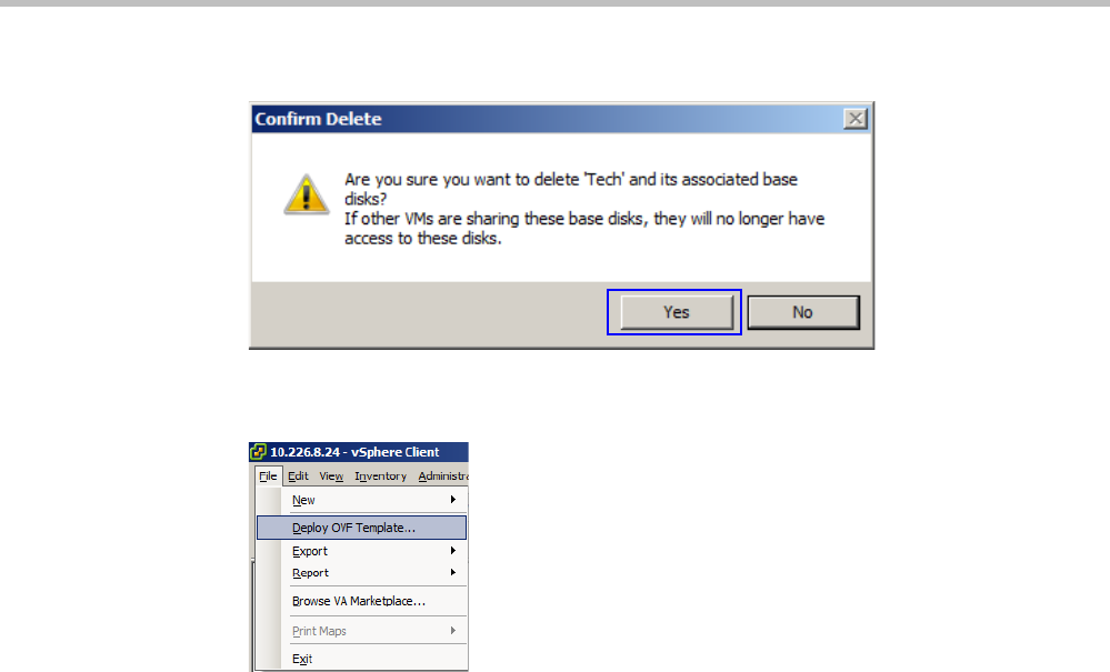
Polycom® RealPresence Collaboration ServerVirtual Edition Administrator’s Guide
19-66 Polycom, Inc.
The Confirm Delete window appears.
22 Click Yes.
23 On the vSphere Client menu, select File > Deploy OVF Template.
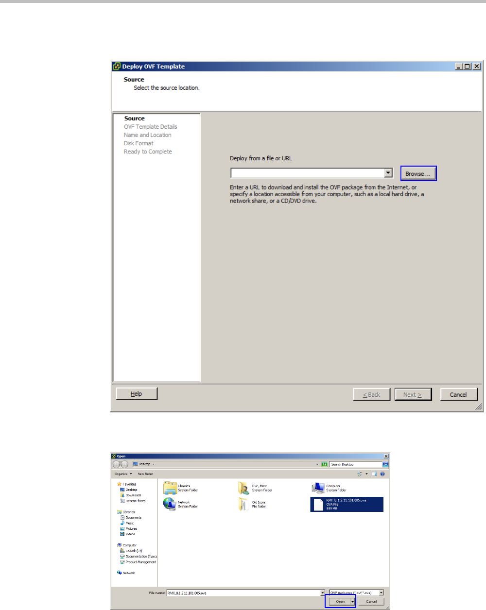
Chapter 19-Collaboration Server Administration and Utilities
Polycom, Inc. 19-67
The Deploy OVF Template wizard opens to the Source page.
24 Click Browse.
The Open dialog box appears.
25 Browse to the new OVA file.
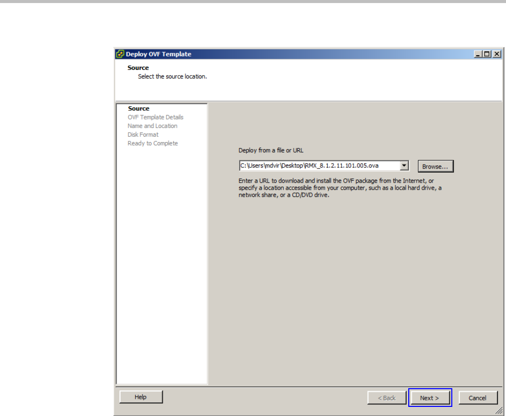
Polycom® RealPresence Collaboration ServerVirtual Edition Administrator’s Guide
19-68 Polycom, Inc.
26 Either double-click on the OVA file or click on the file, then click Open.
27 Click Next.
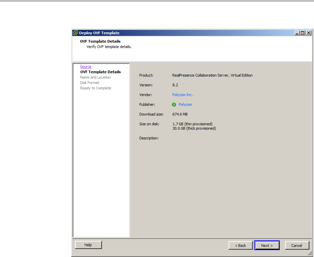
Chapter 19-Collaboration Server Administration and Utilities
Polycom, Inc. 19-69
The OVF Template Details page is displayed.
28 Click Next.
The Name and Location page is displayed.
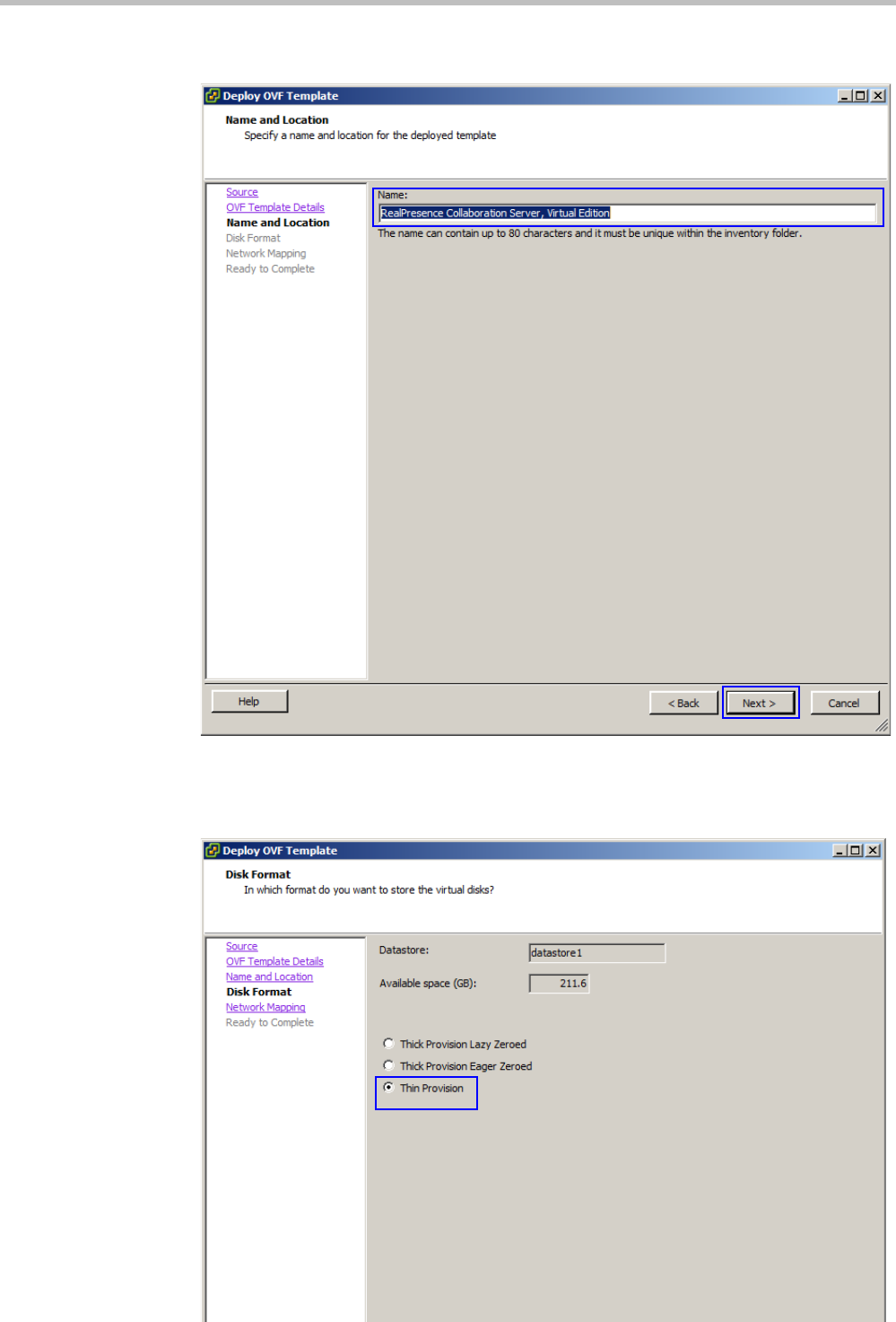
Polycom® RealPresence Collaboration ServerVirtual Edition Administrator’s Guide
19-70 Polycom, Inc.
29 In the Name field, type the same name previously used for the MCU.
30 Click Next.
The Disk Format page is displayed.
31 Select Thin Provision, then click Next.
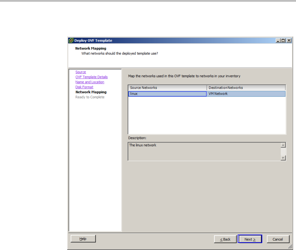
Chapter 19-Collaboration Server Administration and Utilities
Polycom, Inc. 19-71
The Network Mapping page is displayed.
32 Select the appropriate network mappings, then click Next.
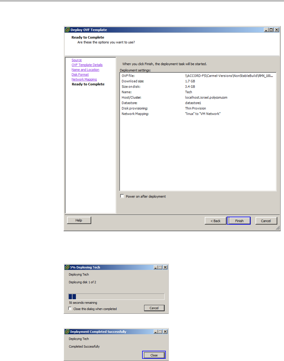
Polycom® RealPresence Collaboration ServerVirtual Edition Administrator’s Guide
19-72 Polycom, Inc.
The Ready to Complete page is displayed.
33 Verify that Power on after deployment is not selected.
34 Confirm that all the settings are correct, then click Finish.
The vSphere Client deploys the OVF file.
When the deployment is complete the following window appears:
35 Click Close.
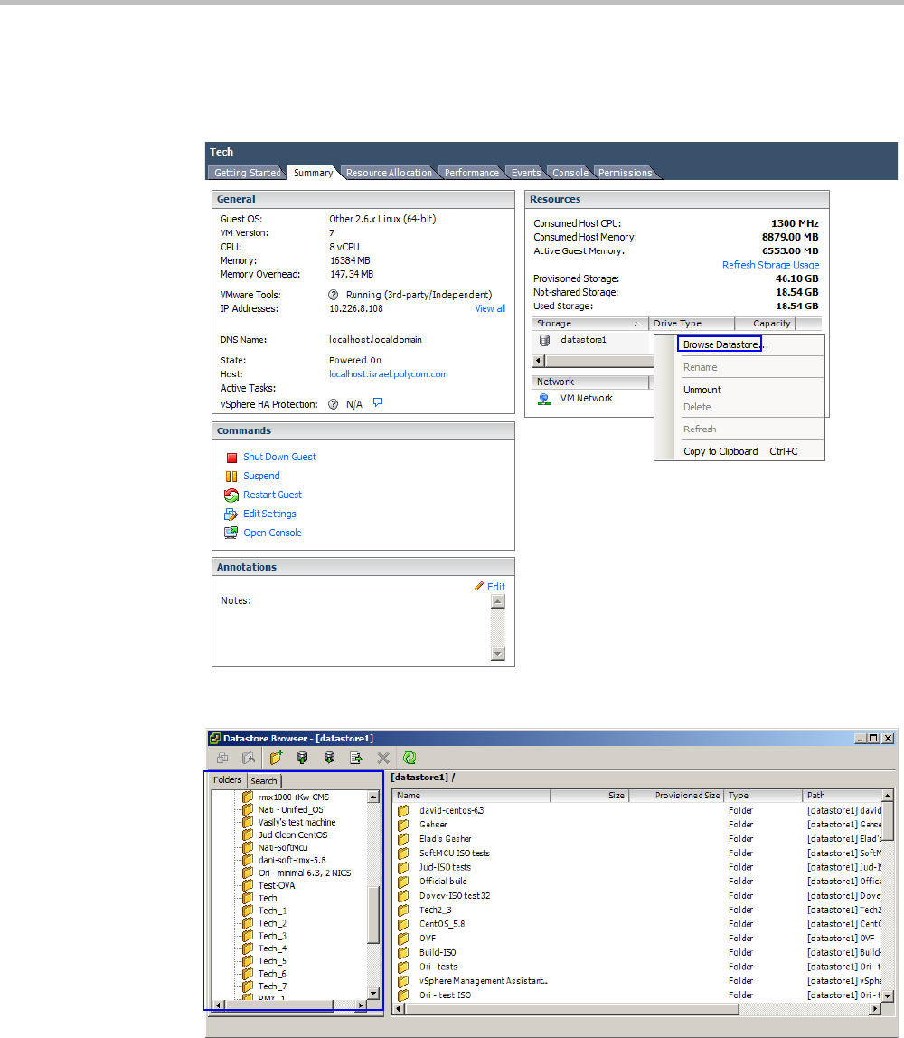
Chapter 19-Collaboration Server Administration and Utilities
Polycom, Inc. 19-73
36 In the Inventory Panel, select the Datastore that used to house the MCU.
37 Click the Summary tab.
38 Under Resources, right-click the datastore, and click Browse Datastore.
The Browse Datastore window appears.
39 In the Folders tab, select the folder whose name matches that of the MCU. The folder
name will have an underscore and a number at the end.
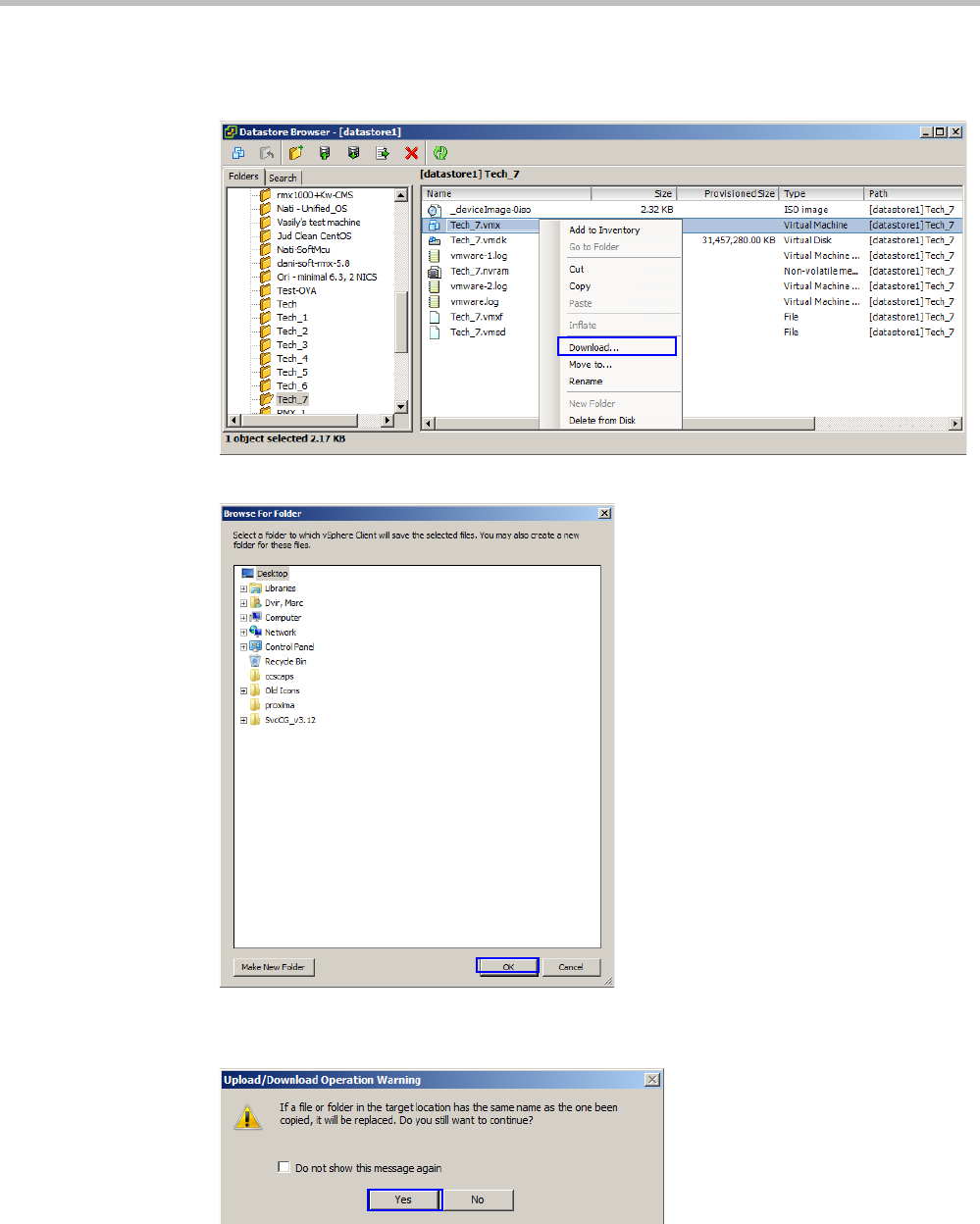
Polycom® RealPresence Collaboration ServerVirtual Edition Administrator’s Guide
19-74 Polycom, Inc.
The contents of the folder are displayed.
40 Right-click the file ending with “.vmx” and click Download.
The Browse For Folder window appears.
41 Browse to a location and click OK.
The Upload/Download Operation Warning window may appear.
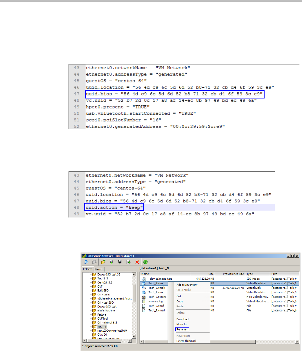
Chapter 19-Collaboration Server Administration and Utilities
Polycom, Inc. 19-75
42 If the Upload/Download Operation Warning window appears, click Yes. If it does not
appear, proceed to Step 43.
The file downloads.
43 Open the file created in Step 18.
44 Open the file in any plain text editor.
45 Locate the line that starts with, uuid.bios.
46 Replace that line with the line saved in the other text file.
47 Add the following as a separate line to the file, including the quotation marks:
uuid.action = “keep”
48 Save and close the file.
49 Optional. To back up the previous configuration:
aIn the Datastore Browser window, right-click the .vmx file, then select Rename.
bChange the file extension to “.bak”.
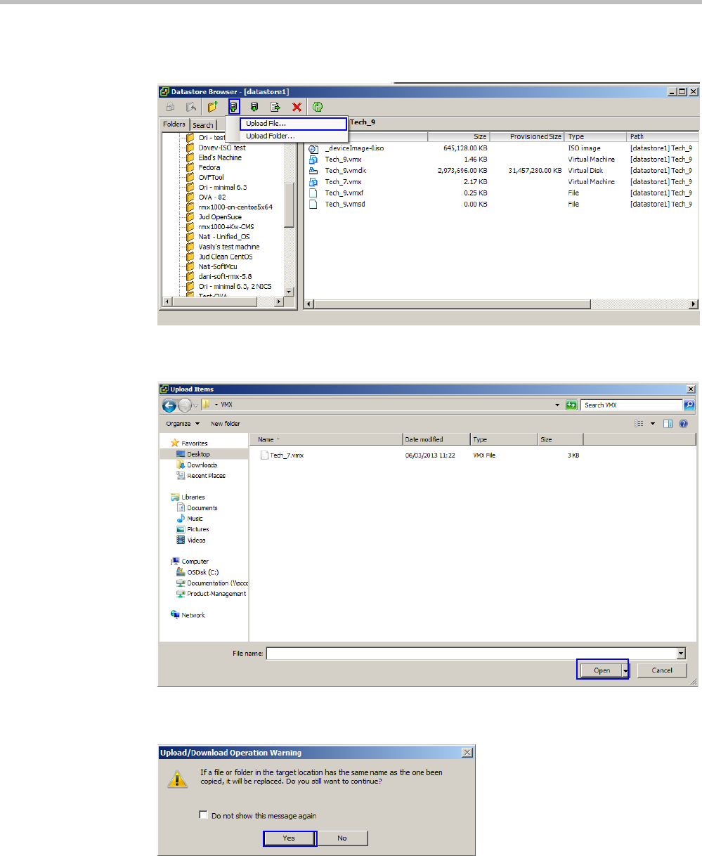
Polycom® RealPresence Collaboration ServerVirtual Edition Administrator’s Guide
19-76 Polycom, Inc.
50 In the tool bar of the Datastore Browser window, click the Upload files to this datastore
button.
51 Click Upload File.
The Upload Items window appears.
52 Navigate to where you saved the “.vmx” file in Step 48, select it, then click Open.
The Upload/Download Operation Warning window may appear.
53 If the Upload/Download Operation Warning window appears, click Yes.
The file is uploaded.
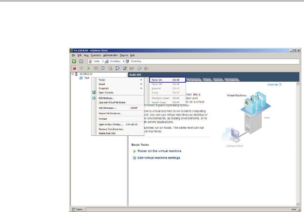
Chapter 19-Collaboration Server Administration and Utilities
Polycom, Inc. 19-77
54 Close the Datastore Browser.
55 In the Inventory Panel, click the Datastore that houses the MCU.
56 Right-click the MCU virtual machine, then click Power > Power On.
After a few minutes, the MCU turns on.
57 Start the Collaboration Server Web Client application on the workstation.
aIn the browser’s address line, enter the IP address of the Control Unit in the format:
http://<Control Unit IP Address>:8080.
bClick Enter.
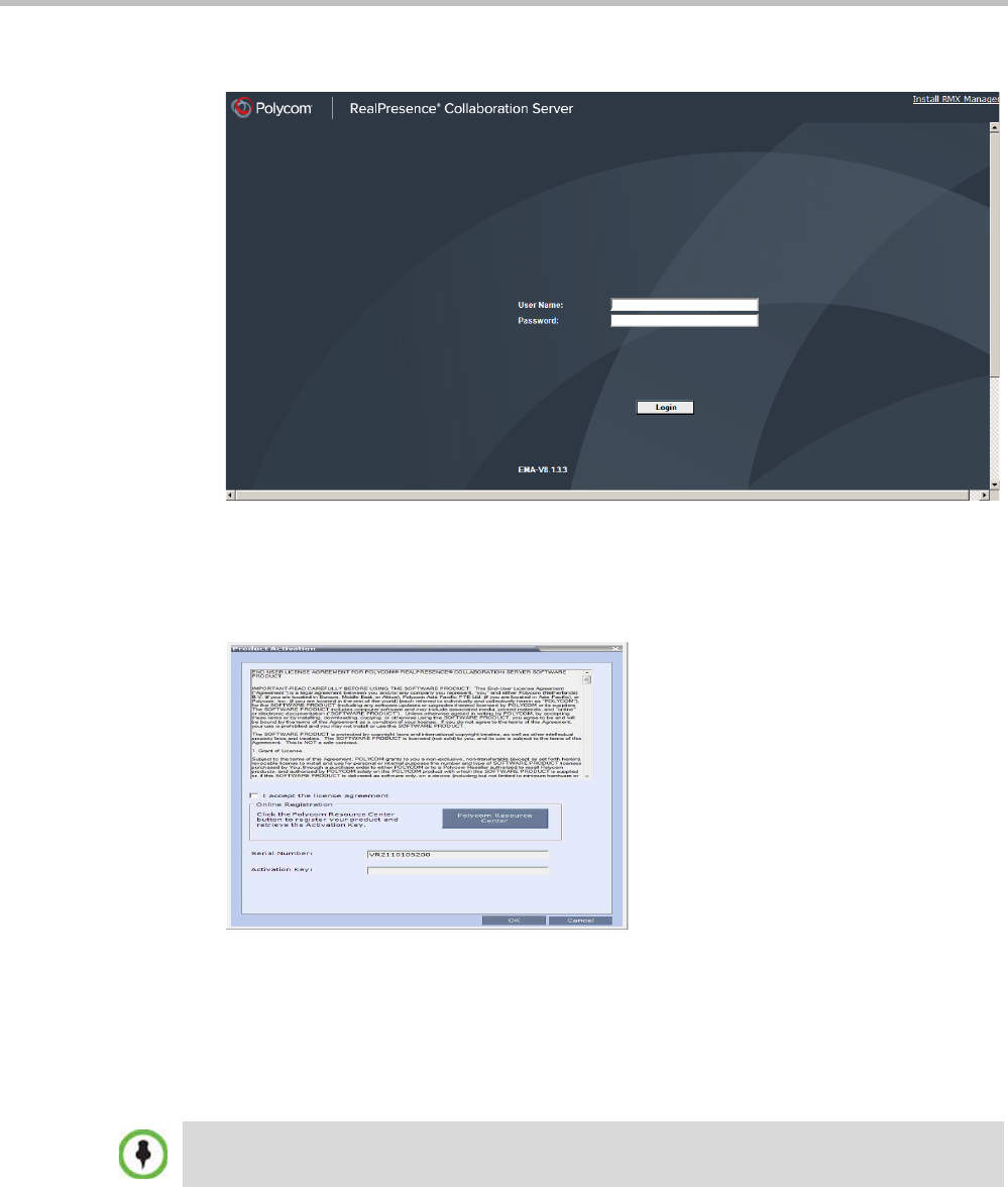
Polycom® RealPresence Collaboration ServerVirtual Edition Administrator’s Guide
19-78 Polycom, Inc.
The Collaboration Server Web Client Login screen is displayed.
58 In the Collaboration Server Web Client Login screen, enter the default Username
(POLYCOM) and Password (POLYCOM) and click Login.
The Collaboration Server Web Client opens and the Product Activation dialog box appears
with the serial number filled in:
59 In the Activation Key field, enter or paste the Product Activation Key that was used on the
previous MCU.
60 Click OK.
A message indicating that the Product Activation Key was loaded successfully appears.
If the Product Activation Key fails to load, please contact your vendor.
61 Click OK.
62 On the RealPresence Collaboration Server menu, click Administration > Software
Management > Restore Configuration.
63 Browse to the Restore Directory Path where the backed up configuration files are stored
and then click Restore.
If the Product Activation dialog box does not appear, go to Setup --> Product Activation to display
the dialog box.

Chapter 19-Collaboration Server Administration and Utilities
Polycom, Inc. 19-79

Polycom® RealPresence Collaboration ServerVirtual Edition Administrator’s Guide
19-80 Polycom, Inc.
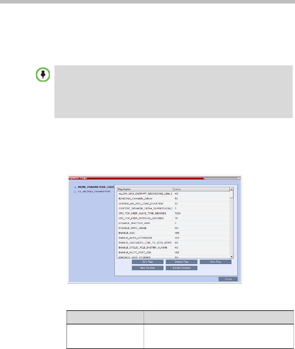
Polycom, Inc. 20-1
20
System Configuration Flags
The system’s overall behavior can be configured by modifying the default values of the
System Flags.
Modifying System Flags
To modify system flags:
1On the Collaboration Server menu, click Setup > System Configuration.
The System Flags dialog box opens.
2In the MCMS_PARAMETERS tab, the following flags can be modified:
For flag changes (including deletion) to take effect, the MCU must be reset. For more information,
see 2.
The following System Flags do not require an MCU reset:
•IVR_MESSAGE_VOLUME
•IVR_MUSIC_VOLUME
•IVR_ROLL_CALL_VOLUME
•ENABLE_SELECTIVE_MIXING
Table 20-1 System Flags – MCMS_PARAMETERS
Flag Description
ALLOW_NON_ENCRYPT_P
ARTY_IN_ENCRYPT_CONF
If YES, allows non-encrypted participants to connect to
encrypted conferences.
Default: No

Polycom® RealPresence Collaboration ServerVirtual Edition Administrator’s Guide
20-2 Polycom, Inc.
ALLOW_NON_ENCRYPT_R
ECORDING_LINK_IN_ENCR
YPT_CONF
When set to NO (default), the Recording Link inherits the
encryption settings of the conference. If the conference is
encrypted, the recording link will be encrypted.
When set to YES, it disables the encryption of the recording
link, regardless of the Encryption settings of the conference
and RSS recorder.
BONDING_CHANNEL_DELA
Y
(ISDN)
When connecting a bonding group, this is the delay (number
of 1/100 seconds) between dialing attempts to connect
sequential channels.
The channel per second connection performance of ISDN
switches can vary and can cause timing issues that result in
bonding channel disconnection.
Default: 6
CHANGE_AD_HOC_CONF_
DURATION
The duration of an ad-hoc conference* can be configured on
a system level by setting the flag to one of the following
values (in minutes): 60 (default), 90, 180 and 270.
* An ad-hoc conference is automatically created when the participant
dials into an Ad-hoc Entry Queue and enters a conference ID that is
not being used by any other conferencing entity. It is based on the
Conference Profile assigned to the EQ.
CONTENT_SLAVE_LINKS_I
NTRA_SUPPRESSION_IN_S
ECONDS
Defines the interval, in seconds, during which the
Collaboration Server is allowed to forward an Intra Request
received from any of the Slave Cascading Links. The Slave
Cascading Link can be connected to the local Collaboration
Server, to an MCU on a higher cascade level or to the
Content sharer.
The first Intra request that is received from any of the Slave
MCUs connected to the Collaboration Server starts the
interval counter and is forwarded to the next level MCU or to
the Content sharer.
All other Intra requests that are received within this interval
are registered but ignored. After an interval of <flag value>
seconds, the system checks if during the last interval any
additional Intra requests were registered. If there is at least
one Intra request it will be forwarded. If there is no additional
Intra request not no action is taken other than to wait for the
next cycle.
This filtering process is repeated every <flag value> seconds.
Default: 30
Table 20-1 System Flags – MCMS_PARAMETERS (Continued)
Flag Description

Chapter 20-System Configuration Flags
Polycom, Inc. 20-3
CONTENT_SPEAKER_INTR
A_SUPPRESSION_IN_SEC
ONDS
This flag controls the requests to refresh (intra) the content
sent from the Collaboration Server system to the content
sender as a result of refresh requests initiated by other
conference participants.
Enter the interval in seconds between the Intra requests sent
from the Collaboration Server to the endpoint sending the
content to refresh the content display. Refresh requests that
will be received from endpoints within the defined interval will
be postponed to the next interval.
Default setting: 5
CPU_TCP_KEEP_ALIVE_TI
ME_SECONDS
This flag indicates when to send the first KeepAlive indication
to check the TCP connection.
Default value: 7200 second (120 minutes)
Range: 600-18000 seconds
When there are NAT problems, this default may be too long
and the TCP connection is lost. In such a case, the default
value should be changed to 3600 seconds (60 minutes) or
less.
CPU_TCP_KEEP_INTERVAL
_SECONDS
This flag indicates the interval in seconds between the
KeepAlive requests.
Default value: 75 second
Range: 10-720 seconds.
DISABLE_INACTIVE_USER Users can be automatically disabled by the system when they
do not log into the Collaboration Server application for a
predefined period.
Possible Values: 0 - 90 days.
Default: 0 (disables this option).
ENABLE_ACCEPTING_ICM
P_REDIRECT
When set to YES, allows the RMX to accept ICMP Redirect
Messages (ICMP message type #5).
Possible values: YES / NO
•Default: YES
ENABLE_AGC Set this flag to YES to enable the AGC option. (Default setting
is NO.) When disabled, selecting the AGC option in the
Participant Properties has not effect on the participant audio.
For more information see "Managing the Address Book” on
page 8-7.
The Auto Gain Control mechanism regulates noise and audio
volume by keeping the received audio signals of all
participants balanced.
Note:
Enabling AGC may result in amplification of background
noise.
ENABLE_CASCADED_LINK
_TO_JOIN_WITHOUT_PASS
WORD
Enables a cascaded link to enter a conference without a
password.
Default: NO, for security reasons.
Table 20-1 System Flags – MCMS_PARAMETERS (Continued)
Flag Description

Polycom® RealPresence Collaboration ServerVirtual Edition Administrator’s Guide
20-4 Polycom, Inc.
ENABLE_CYCLIC_FILE_SY
STEM_ALARMS
Enables or disables the display of Active Alarms before
overwriting the older CDR/Auditor/Log files, enabling the
users to backup the older files before they are deleted.
Default: NO
ENFORCE_SAFE_UPGRAD
E
When set to YES this flag enables the Collaboration Server
system to notify users when an incorrect version upgrade/
downgrade or upgrade/downgrade path is selected.
When set to NO, after initiating an upgrade or downgrade
software installation, the Collaboration Server activates a fault
alert in the Faults List: “Warning: Upgrade started and SAFE
Upgrade protection is turned OFF” and the upgrade/
downgrade process continues.
Range: YES / NO
Default: YES
ENABLE_SENDING_ICMP_
DESTINATION_UNREACHA
BLE
Not supported with RealPresence Collaboration Server
Virtual Edition.
EXT_DB_IVR_PROV_TIME_
SECONDS
When an Entry Queue is set as IVR Service Provider for the
RealPresence DMA system, the value here indicates the time
interval in seconds in which the database is accesses for the
ID.
Default: 300
FORCE_CIF_PORT_ALLOC
ATION
Sets the MCU to allocate one CIF video resource to an
endpoint, regardless of the resolution determined by the
Conference Profile parameters. You can specify the endpoint
types for which resource allocation can be forced to CIF
resource, enabling other types of endpoints to use higher
resolutions in the same conference.
Enter the product type to which the CIF resource should be
allocated. Possible values are:
•CMA Desktop - for CMA desktop client
•VSX nnnn - where nnnn represents the model number for
example, VSX 8000.
FORCE_STRONG_PASSWO
RD_POLICY
When set to YES , implements the Strong Password rules.
For more details, see “Changing a User’s Password” on
page 14-3.
Default: NO
FORCE_SYSTEM_BROADC
AST_VOLUME
If set to YES, the level of broadcasting volume of the
connected participant is value taken from the system flag
SYSTEM_BROADCAST_VOLUME.
If set to NO (default), the broadcasting volume level is 5.
FORCE_SYSTEM_LISTENIN
G_VOLUME
If set to YES, the level of listening volume of the connected
participant is value taken from the system flag
SYSTEM_LISTENING_VOLUME.
If set to NO (default), the listening volume level is 5.
Table 20-1 System Flags – MCMS_PARAMETERS (Continued)
Flag Description

Chapter 20-System Configuration Flags
Polycom, Inc. 20-5
GK_MANDATORY_FOR_CA
LLS_IN
If set to YES, a gatekeeper is required to receive incoming
H.323 calls. If a gatekeeper is not configure in the
Collaboration Server, the calls will fail.
If set to NO (default), gatekeeper is not required to process
H.323 incoming calls and H.323 participants can dial in with
or without a gatekeeper.
GK_MANDATORY_FOR_CA
LLS_OUT
If set to YES, a gatekeeper is required to perform H.323
outgoing calls. If a gatekeeper is not configure on the
Collaboration Server, the calls will fail.
If set to NO (default), gatekeeper is not required to dial out to
H.323 participants and calls can be dialed out with or without
a gatekeeper.
H263_ANNEX_T Set to NO to send the content stream without Annex T and
enable Aethra and Tandberg endpoints, that do not support
Annex T, to process the content.
Default: YES
HD_THRESHOLD_BITRATE Sets the minimum bit rate required by endpoints to connect to
an HD Conference. Endpoints that cannot support this bit rate
are connected as audio only.
Range: 384kbps - 4Mbs (Default: 768)
IVR_MESSAGE_VOLUME The volume of IVR messages varies according to the value of
this flag.
Possible value range: 0-10 (Default: 6).
0 – disables playing the IVR messages
1 – lowest volume
10 – highest volume
Notes:
•It is not recommended to disable IVR messages by setting
the flag value to 0.
•System reset is not required for flag changes to take
effect.
IVR_MUSIC_VOLUME The volume of the IVR music played when a single participant
is connected to the conference varies according to the value
of this flag.
Possible value range: 0-10 (Default: 5).
0 – disables playing the music
1 – lowest volume
10 – highest volume
Note: System reset is not required for flag changes to take
effect.
Table 20-1 System Flags – MCMS_PARAMETERS (Continued)
Flag Description

Polycom® RealPresence Collaboration ServerVirtual Edition Administrator’s Guide
20-6 Polycom, Inc.
IVR_ROLL_CALL_VOLUME The volume of the Roll Call varies according to the value of
this flag.
Possible value range: 0-10 (Default: 6).
0 – disables playing the Roll Call
1 – lowest volume
10 – highest volume
Note:
•It is not recommended to disable the Roll Call by setting
the flag value to 0.
•System reset is not required for flag changes to take
effect.
LAST_LOGIN_ATTEMPTS If YES, the system displays a record of the last Login of the
user.
Default: NO.
.
LEGACY_EP_CONTENT_DE
FAULT_LAYOUT
Defines the video layout to be displayed on the screen of the
legacy endpoints when switching to Content mode.
Default value: CP_LAYOUT_1P7 (1+7).
MAX_CONF_PASSWORD_R
EPEATED_CHAR
Allows the administrator to configure the maximum number of
consecutive repeating characters that are to be allowed in a
conference password.
Range: 1 - 4
Default: 2
MAX_CP_RESOLUTION The MAX_CP_RESOLUTION flag value is applied to the
system during First Time Power-on and after a system
upgrade. The default value is HD720.
All subsequent changes to the Maximum CP Resolution of
the system are made using the Resolution Configuration
dialog box.
Possible flag values:
•
MPM+ /
HD1080 - High Definition at 60 fps
•HD720 – High Definition at 60 fps
•HD – High Definition at 30 fps
•SD30 – Standard Definition at 30 fps
•SD15 – Standard Definition at 15 fps
•CIF – CIF resolution
Default: HD1080
For more information see "Video Resolutions in AVC-based
CP Conferencing” on page 4-1.
Note: From Version 8.1, MPM+ media card is not supported.
Table 20-1 System Flags – MCMS_PARAMETERS (Continued)
Flag Description

Chapter 20-System Configuration Flags
Polycom, Inc. 20-7
MAX_INTRA_REQUESTS_P
ER_INTERVAL_
Enter the maximum number of refresh (intra) requests for the
Content channel sent by the participant’s endpoint in a 10
seconds interval that will be dealt by the Collaboration Server
system. When this number is exceeded, the Content sent by
this participant will be identified as noisy and his/her requests
to refresh the Content display will be suspended.
Default setting: 3
MAX_INTRA_SUPPRESSIO
N_DURATION_IN_SECOND
S_
Enter the duration in seconds to ignore the participant’s
requests to refresh the Content display.
Default setting: 10
MAX_NUMBER_OF_MANAG
EMENT_SESSIONS_PER_S
YSTEM
Defines the maximum number of concurrent management
sessions (http and https connections) per system.
Value: 4 - 80
Default: 80
MAX_NUMBER_OF_MANAG
EMENT_SESSIONS_PER_U
SER
Defines the maximum number of concurrent management
sessions (http and https connections) per user.
Value: 4 - 80
Default: 10
MAX_PASSWORD_REPEAP
ED_CHAR
Allows the administrator to configure the maximum number of
consecutive repeating characters to be allowed in a user
password.
Range: 1 - 4
Default: 2
MCU_DISPLAY_NAME The name of the MCU that is displayed on the endpoint’s
screen when connecting to the conference.
Default: POLYCOM RealPresence Collaboration Server
800sPOLYCOM
MIN_PASSWORD_LENGTH The length of passwords.
Possible value: between 0 and 20.
0 means this rule is not enforced.
MIN_PWD_CHANGE_FREQ
UENCY_IN_DAYS
Defines the frequency with which a user can change a
password.
Values: 0 -7.
0 (standard default) - users do not have to change their
passwords.
MIN_SYSTEM_DISK_SPACE
_TO_ALERT
Defines a minimum remaining Collaboration Server disk
capacity in megabytes. If the remaining disk capacity falls
below this level an active alarm is raised.
Default: 2048
MS_ENVIRONMENT If YES, sets the Collaboration Server SIP environment to
integrate with Microsoft OCS solution.
Default: NO
Table 20-1 System Flags – MCMS_PARAMETERS (Continued)
Flag Description

Polycom® RealPresence Collaboration ServerVirtual Edition Administrator’s Guide
20-8 Polycom, Inc.
MULTIPLE_SERVICES Determines whether the Multiple Services option is be
activated once the appropriate license is installed.
Possible Values: YES / NO
Default: NO
NUMERIC_CHAIR_PASS_D
EFAULT_LEN
This flag enables or disables the automatic generation of
chairperson passwords and determines the number of digits
in the chairperson passwords assigned by the MCU.
Possible values are:
•0 disables the automatic password generation.
Any value other than 0 enables the automatic generation
of chairperson passwords if the flag
HIDE_CONFERENCE_PASSWORD is set to NO.
•1 – 16, default: 6 (Standard Security Mode)
If the default is used, in non-secured mode the system will
automatically generate chairperson passwords that contain 6
characters.
NUMERIC_CHAIR_PASS_M
AX_LEN
The maximum number of digits that the user can enter when
manually assigning a password to the chairperson.
Range: 0 – 16
Default: 16
NUMERIC_CHAIR_PASS_MI
N_LEN
Defines the minimum length required for the Chairperson
password.
Value: 0-16
Default: 0 - this rule is not enforced.
NUMERIC_CONF_ID_LEN Defines the number of digits in the Conference ID that will be
assigned by the MCU. Enter 0 to disable the automatic
assignment of IDs by the MCU and let the Collaboration
Server user manually assign them.
Range: 2-16 (Default: 4).
NUMERIC_CONF_ID_MAX_
LEN
The maximum number of digits that the user can enter when
manually assigning an ID to a conference.
Range: 2-16 (Default: 8)
Note: Selecting 2 limits the number of simultaneous ongoing
conferences to 99.
NUMERIC_CONF_ID_MIN_L
EN
The minimum number of digits that the user must enter when
manually assigning an ID to a conference.
Range: 2-16 (Default: 4)
Note: Selecting 2 limits the number of simultaneous ongoing
conferences to 99.
Table 20-1 System Flags – MCMS_PARAMETERS (Continued)
Flag Description

Chapter 20-System Configuration Flags
Polycom, Inc. 20-9
NUMERIC_CONF_PASS_DE
FAULT_LEN
This flag enables or disables the automatic generation of
conference passwords and determines the number of digits in
the conference passwords assigned by the MCU.
Possible values are:
•0 disables the automatic password generation.
Any value other than 0 enables the automatic generation
of conference passwords if the flag
HIDE_CONFERENCE_PASSWORD is set to NO.
•1 – 16, default: 6
If the default is used, in non-secured mode the system will
automatically generate conference passwords that contain 6
characters.
NUMERIC_CONF_PASS_MA
X_LEN
The maximum number of digits that the user can enter when
manually assigning a password to the conference.
Range: 0 – 16
Default (both Modes): 16
NUMERIC_CONF_PASS_MI
N_LEN
Defines the minimum length required for the Conference
password.
Value: 0-16
•Default: 0 - this rule is not enforced.
PAL_NTSC_VIDEO_OUTPU
T
When set to AUTO (default), the video output sent by the
Collaboration Server is either PAL or NTSC format,
depending on the current speaker in the layout. This ensures
full synchronization between the frame rate of the speaker
and the video encoder, ensuring smoother video.
In environments where the majority of endpoints are
configured to either NTSC or PAL, the flag can be set
accordingly to change the video encoding of the Collaboration
Server to be compatible with the majority of endpoints in the
call.
Possible Values: AUTO, PAL, NTSC
PASSWORD_EXPIRATION_
DAYS
Determines the duration of password validity.
Value: between 0 and 90 days.
0 - user passwords do not expire.
PASSWORD_EXPIRATION_
DAYS_MACHINE
Enables the administrator to change the password expiration
period of Application-user’s independently of regular users.
Default: 365 (days).
PASSWORD_EXPIRATION
_WARNING_DAYS
Determines the display of a warning to the user of the number
of days until password expiration.
Value: between 0 and 14 days.
0 - password expiry warnings are not displayed.
PASSWORD_HISTORY_SIZ
E
The number of passwords that are recorded to prevent users
from re-using their previous passwords.
Values are between 0 and 16.
0 (standard default) - the rule is not enforced.
Table 20-1 System Flags – MCMS_PARAMETERS (Continued)
Flag Description

Polycom® RealPresence Collaboration ServerVirtual Edition Administrator’s Guide
20-10 Polycom, Inc.
RESTRICT_CONTENT_BRO
ADCAST_TO_LECTURER
If set to YES, only the conference lecturer may send content
to the conference.
If set to NO, any conference participant can send content.
Default: YES
RRQ_WITHOUT_GRQ To enable registration, some gatekeepers require sending
first RRQ and not GRQ.
Set flag to YES, if this behavior is required by the gatekeeper
in your environment.
Default: NO.
GRQ (Gatekeeper Request) - Gatekeeper discovery is the
process an endpoint uses to determine which gatekeeper to
register with.
RRQ - registration request sent to the gatekeeper.
SEPARATE_MANAGEMENT
_NETWORK
Enables/disables the Network Separation
Default: NO.
SESSION_TIMEOUT_IN_MI
NUTES
If there is no input from the user or if the connection is idle for
longer than the number of minutes specified by this flag, the
connection to the Collaboration Server is terminated.
Value: 0-999
0 - Session Timeout is disabled.
Default: 0
SIP_AUTO_SUFFIX_EXTEN
SION
Used to automatically add a suffix to a SIP address (To
Address) instead of adding it manually in the Collaboration
Server Web Client (SIP address) when the SIP call is direct-
dial and not through a Proxy.
Example:
Participant Name = john.smith
Company Domain = maincorp.com
SIP_AUTO_SUFFIX_EXTENSION flag value =
@maincorp.com
Entering john.smith will generate a SIP URI =
john.smith@maincorp.com
STAR_DELIMITER_ALLOWE
D
When set to YES, an asterisk “*” can be used as a delimiter in
Conference and Meeting Room dial strings.
The dial string is first searched for “'#' first followed by “*”.
Default: NO
Table 20-1 System Flags – MCMS_PARAMETERS (Continued)
Flag Description

Chapter 20-System Configuration Flags
Polycom, Inc. 20-11
SYSTEM_BROADCAST_VO
LUME
This value is used when the system flag
FORCE_SYSTEM_BROADCAST_VOLUME is set to YES.
Determines the default audio level with which the participants
connects and sends audio to the conference.
The volume scale is from 1 to 10, where 1 is the weakest and
10 is the strongest. The default connection value is 5.
Each unit change represents an increase or decrease of 3 dB
(decibel).
Range: 1-10
Default: 5
SYSTEM_LISTENING_VOLU
ME
This value is used when the system flag
FORCE_SYSTEM_LISTENING_VOLUME is set to YES.
Determines the default audio level with which the participants
connects and receives audio from the conference.
The volume scale is from 1 to 10, where 1 is the weakest and
10 is the strongest. The default value is 5. Each unit change
represents an increase or decrease of 3 dB (decibel).
Range: 1-10
Default: 5
TERMINATE_CONF_AFTER
_CHAIR_DROPPED
From Version 8.1, this flag’s functionality is replaced by the
Terminate Conference after Chairperson Drops check box
in the Profile - IVR dialog box.
In versions prior to 8.1, if YES, sets conferences to
automatically terminate if the Chairperson disconnects from
the conference. This takes effect only if the Conference
Requires Chairperson check box in the Conference Profile
Properties, IVR Tab, is selected.
Default: YES
Note: In order for the "Chairperson Exit" message to be
played this flag must be set to YES.
USER_LOCKOUT If YES, a user is locked out of the system after three
consecutive Login failures with same User Name. The user is
disabled and only the administrator can enable the user
within the system.
Default: NO
USER_LOCKOUT_DURATIO
N_IN_MINUTES
Defines the duration of the Lockout of the user.
Value: 0 - 480
0 means permanent User Lockout until the administrator re-
enables the user within the system.
Default: 0
USER_LOCKOUT_WINDOW
_IN_MINUTES
Defines the time period during which the three consecutive
Login failures occur.
Value: 0 - 45000
0 means that three consecutive Login failures in any time
period will result in User Lockout.
Default: 60
Table 20-1 System Flags – MCMS_PARAMETERS (Continued)
Flag Description
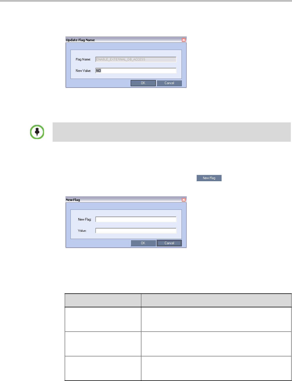
Polycom® RealPresence Collaboration ServerVirtual Edition Administrator’s Guide
20-12 Polycom, Inc.
3To modify a flag value, double-click or select the flag and click the Edit Flag button.
4In the New Value field, enter the flag’s new value.
5Click OK to close the Update Flag dialog box.
6Repeat steps 2–4 to modify additional flags.
7Click OK to close the System Flags dialog box
Manually Adding and Deleting System Flags
To add a flag:
1In the System Flags dialog box, click the New Flag ( ) button.
The New Flag dialog box is displayed.
2In the New Flag field enter the flag name.
3In the Value field enter the flag value.
The following flags can be manually added to the MCMS_PARAMETERS tab:
For flag changes (including deletion) to take effect, reset the MCU. For more information see
"Resetting the Collaboration Server” on page 19-57.
Table 20-2 Manually Added System Flags – MCMS_PARAMETERS
Flag Description
802_1X_CERTIFICATE_MO
DE
Not supported with RealPresence Collaboration Server Virtual
Edition.
802_1X_SKIP_CERTIFICAT
E_VALIDATION
Not supported with RealPresence Collaboration Server Virtual
Edition.
802_1X_CRL_MODE Not supported with RealPresence Collaboration Server Virtual
Edition.

Chapter 20-System Configuration Flags
Polycom, Inc. 20-13
802_FIPS_MODE Not supported with RealPresence Collaboration Server Virtual
Edition.
ACCEPT_VOIP_DTMF_TYP
E
Defines the type of DTMF tones (inband) or digits (outband)
that the Collaboration Server will accept in VOIP calls.
Range:
•0 - Auto (default):
Inband or outband DTMF tones/digits are accepted
depending on the endpoint's current setting. If the
endpoint switches from inband to outband or visa versa
the value of the SET_DTMF_SOURCE_DIFF_IN_SEC
flag determines the time interval after which both inband
and outband tones/digits will be accepted.
•1 - Outband (H.245) only
•2 - Inband only
ANAT_IP_PROTOCOL If YES, enables Alternative Network Address Types.
Range: DISABLED, AUTO, PREFER_IPv4, PREFER_IPv6
•Default: YES
APACHE_KEEP_ALIVE_TIM
EOUT
If the connection is idle for longer than the number of seconds
specified by this flag, the connection to the Collaboration
Server is terminated.
Value: 0 - 999
Default: 15
Note: A value of 0 results in an unlimited keep-alive duration.
AVOID_VIDEO_LOOP_BAC
K_IN_CASCADE
When set to YES the current speaker’s image is not sent back
through the participant link in cascaded conferences with
conference layouts other than 1x1.
Default: YES
Range: YES / NO
BLOCK_CONTENT_LEGAC
Y_FOR_LYNC
This flag is used to control the system behavior in an
environment where some Lync clients use the Polycom CCS
plug-in and some do not.
When set to NO (default), Content is sent to all Lync clients
over the video channel, including those with the plug-in
installed, even when the Send Content to Legacy Endpoints is
disabled. Other, non-Lync legacy endpoints will not be
affected by this flag and will receive content according to the
Send Content to Legacy Endpoints settings in the conference
Profile.
When set to YES, Content is not sent to Lync clients over the
video channel including those with the Polycom CCS plug-in
installed, even when the Send Content to Legacy Endpoints is
enabled. Other, non-Lync legacy endpoints will not be affected
by this flag and will receive content according to the Send
Content to Legacy Endpoints settings in the conference
Profile.
Table 20-2 Manually Added System Flags – MCMS_PARAMETERS (Continued)
Flag Description

Polycom® RealPresence Collaboration ServerVirtual Edition Administrator’s Guide
20-14 Polycom, Inc.
BURN_BIOS Although not recommended, setting this flag’s value to NO will
prevent BIOS upgrade.
Default: YES.
CAC_ENABLE When set to YES, enables the Call Admission Control
implementation in the Collaboration Server.
Default: NO (CAC is disabled)
CASCADE_LINK_PLAY_TO
NE_ON_CONNECTION
When set to YES, the Collaboration Server plays a tone when
a cascading link between conferences is established. The
tone is played in both conferences.
This tone is not played when the cascading link disconnects
from the conferences.
The tone used to notify that the cascading link connection has
been established cannot be customized.
Default value: NO.
The tone volume is controlled by the same flag as the IVR
messages and tones: IVR_MESSAGE_VOLUME.
CELL_IND_LOCATION Change the location of the display of Network Quality
Indicators displayed in the cells of the conference Video
Layout.
Default: TOP_RIGHT
Range:
•BOTTOM_LEFT
•BOTTOM_RIGHT
•TOP_LEFT
•TOP_RIGHT
CFG_KEY_ENABLE_FLOW_
CONTROL_REINVITE
Used to enable or disable sending a re-INVITE to endpoints to
adjust their data rate. When set to YES, re-INVITE is used for
endpoints that do not support flow control in SIP using either
the Information or RTCP Feedback mechanisms.
Default: NO.
CONF_GATHERING_DURAT
ION_SECONDS
The value of this System Flag sets the duration of the
Gathering Phase in seconds. The Gathering Phase duration
of the conference is measured from the scheduled start time
of the conference.
Range: 0 - 3600
Default: 180
For more information see "Video Preview (AVC Only
Participants)” on page 3-20.
Table 20-2 Manually Added System Flags – MCMS_PARAMETERS (Continued)
Flag Description

Chapter 20-System Configuration Flags
Polycom, Inc. 20-15
CP_REGARD_TO_INCOMIN
G_SETUP_RATE
For use in the Avaya Environment.
If set to YES, the Collaboration Server calculates the line rate
for incoming calls in CP conferences, according to the line
rate which is declared by the endpoint in the H.225 setup
message.
If set to NO, the rate is calculated according to the conference
line rate regardless of the rate in the H.225 setup message.
Default: YES.
CPU_BONDING_LINK_MON
ITORING_FREQUENCY
Used when using the MII Monitor for troubleshooting
networks.This flag sets the MII Polling Interval in milliseconds.
A value of zero disables MII monitoring.
Default: 100
CPU_BONDING_MODE Sets the Bonding Mode of the Signalling and Management
network interface controllers.
Mode=6, balance-alb,
(Adaptive Load Balancing) includes balance-tlb, (Transmit
Load Balancing) and balance-rlb (Receive Load Balancing)
for IPV4 traffic. No special switch support is required.
Receive Load Balancing is achieved by ARP negotiation.
Outbound ARP Replies are intercepted and their source
hardware address is overwritten with the unique hardware
address of one of the slaves in the bond. In this way different
peers will use different hardware addresses for the server.
Note: balance-alb is the only supported value. All other
possible values are for troubleshooting purposes only.
Default: balance-alb
Possible values:
•balance-alb
•balance-rr
•active-backup
•balance-xor
•broadcast
•802.3ad
•balance-tlb
DETECT_SIP_EP_DISCON
NECT _TIMER
The flag value indicates the amount of time in seconds to wait
for an RTCP or RTP message to be received from the
endpoint. When the time that was set in the system flag has
elapsed and no RTCP or RTP audio or video message has
been received on either the audio or the video channel, the
MCU disconnects the SIP endpoint from the conference.
Default: 20 (seconds)
Range: 0 - 300
For more information see "Detecting SIP Endpoint
Disconnection” on page 12-32.
Table 20-2 Manually Added System Flags – MCMS_PARAMETERS (Continued)
Flag Description

Polycom® RealPresence Collaboration ServerVirtual Edition Administrator’s Guide
20-16 Polycom, Inc.
DISABLE_CELLS_NETWOR
K_IND
Disable the display of Network Quality Indicators displayed in
the cells of the conference Video Layout.
Default: YES
Range: YES / NO
DISABLE_DUMMY_REGIST
RATION
Enables or disables SIP dummy registration on the domain.
Possible Values:
NO (Default) - Disables SIP dummy registration.
YES - Enables SIP dummy registration.
Note: For homologation and certification testing, the flag must
be set to YES.
DISABLE_GW_OVERLAY_I
NDICATION
When set to NO (default), displays progress indication during
the connection phase of a gateway call.
Set the value to YES to hide the connection indications
displayed on the participant’s screen during the connection
phase of a gateway call.
DISABLE_SELF_NETWORK
_IND
Disable the display of the Network Quality Indicator of the
participant’s own endpoint.
Default: NO
Range: YES / NO
DISABLE_WIDE_RES_TO_S
IP_DIAL_OUT
When set to NO (default), the Collaboration Server sends
wide screen resolution to dial-out SIP endpoints. Endpoint
types that do not support wide screen resolutions are
automatically identified by the Collaboration Server according
to their product type and version and will not receive the wide
resolution even if the flag is set to YES.
When manually added and set to YES, the Collaboration
Server does not send wide screen.
Default: NO.
DTMF_FORWARD_ANY_DI
GIT_TIMER_SECONDS
Used for DTMF code suppression in cascading conferences.
Determines the time period (in seconds) that MCU A will
forward DTMF inputs from conference A participants to MCU
B.
Flag range (in seconds): 0 - 360000
This flag is defined on MCU A (the calling MCU).
For more information, see"Video Layout in Cascading
conferences (CP and mixed CP and SVC)” on page 5-1.
ENABLE_CISCO_GK When set to YES, it enables the use of an identical prefix for
different Collaboration Servers when registering with a Cisco
MCM Gatekeeper.
Default: NO.
Table 20-2 Manually Added System Flags – MCMS_PARAMETERS (Continued)
Flag Description

Chapter 20-System Configuration Flags
Polycom, Inc. 20-17
ENABLE_CLOSED_CAPTIO
N
Enables or disables the Closed Captions option that allow
endpoints to endpoints to provide real-time text transcriptions
or language translations of the video conference.
When set to NO (default), Closed Captions are disabled.
When set to YES, Closed Captions are enabled.
ENABLE_EPC When set to YES (default), enables Polycom proprietary
People+.
When set to NO, disables this feature for all conferences and
participants.
ENABLE_EXTERNAL_DB_A
CCESS
If YES, the Collaboration Server connects to an external
database application, to validate the participant’s right to start
a new conference or access a conference.
Default: NO
ENABLE_H239 When set to YES, Content is sent via a separate Content
channel. Endpoints that do not support H.239 Content sharing
will not be able to receive
When set to NO, the Content channel is closed. In such a
case, H.239 Content is sent via the video channel (“people”
video) enabling endpoints that do not support H.239 Content
sharing to receive the Content in their video channel.
Default: YES.
ENABLE_H239_ANNEX_T In H.239-enabled MIH Cascading, when MGC is on level 1,
enables sending Content using Annex T.
ENABLE_LYNC_RTCP_INT
RA
When set to YES, RTCP FIR is used for sending Intra
Requests. When set to NO Intra Requests are sent using SIP
INFO Messages.
Range: YES / NO
Default: NO
ENABLE_MS_FEC Enables the Microsoft FEC (Forward Error Correction)
support for RTV.
Range: Auto/No
Default: Auto
When set to Auto, FEC support is enabled. FEC uses the
DV00 option (DV=00 - one FEC per frame using XOR). When
set to No, FEC support is disabled.
ENABLE_NO_VIDEO_RESO
URCES_AUDIO_ONLY_MES
SAGE
Enables playing a voice message that Informs the participant
of the lack of Video Resources in the Collaboration Server
and that he/she is being connected as Audio Only.
Default: YES
Table 20-2 Manually Added System Flags – MCMS_PARAMETERS (Continued)
Flag Description

Polycom® RealPresence Collaboration ServerVirtual Edition Administrator’s Guide
20-18 Polycom, Inc.
ENABLE_SELECTIVE_MIXI
NG
Enables (default) or disables the Automatic muting of noisy
AVC endpoints. For more details, see "Permanent
Conference” on page 3-49.
When set to YES, the automatic muting of noisy endpoints
can be enabled or disabled at the conference level in the
Conference Profile - Audio Settings dialog box.
When set to NO, the automatic muting of noisy endpoints is
disabled at the conference level and cannot be enabled in the
Conference Profile - Audio Settings dialog box.
Default: YES
Note: MCU reset is not required when changing the flag
value.
ENABLE_SIP_PEOPLE_PLU
S_CONTENT
If security is of higher priority than SIP Content sharing, SIP
People+Content can be disabled by setting this System Flag
to NO. (The content management control (BFCP) utilizes an
unsecured channel (60002/TCP) even when SIP TLS is
enabled.)
Default: YES
ENABLE_SIP_PPC_FOR_AL
L_USER_AGENT
When set to YES, SIP People+Content and BFCP capabilities
are declared with all vendors’ endpoints.
Default: YES
Range: YES / NO
ENABLE_SIRENLPR Enable / disable SirenLPR Audio Algorithm for use in IP
(H.323, SIP) calls in both CP and VSW conferences.
Range: YES / NO
Default: YES
ENABLE_SIRENLPR_SIP_E
NCRYPTION
Enables the SirenLPR audio algorithm when using encryption
with the SIP protocol.
Range: YES / NO
Default: NO
ENABLE_TC_PACKAGE Enables or disables Network Traffic Control.
Range: YES / NO
Default: NO
ENABLE_TEXTUAL_CONFE
RENCE_STATUS
Set the value of this flag to NO to disable Text Indication. This
setting is recommended for MCUs running Telepresence
conferences.
Default: YES.
ENABLE_VIDEO_PREVIEW Enables the Video Preview feature.
Default: YES.
For more details, see "Video Preview (AVC Only Participants)”
on page 3-20.
EXTERNAL_CONTENT_
DIRECTORY
The Web Server folder name. Change this name if you have
changed the default names used by the CMA/XMA
application.
Default: /PlcmWebServices
Table 20-2 Manually Added System Flags – MCMS_PARAMETERS (Continued)
Flag Description

Chapter 20-System Configuration Flags
Polycom, Inc. 20-19
EXTERNAL_CONTENT_IP Enter the IP address of the CMA/XMA server in the format:
http://[IP address of the CMA server].
For example, http://172.22.185.89.
This flag is also the trigger for replacing the internal
Collaboration Server address book with the CMA global
Address Book.
When empty, the integration of the CMA address book with
the Collaboration Server is disabled.
EXTERNAL_CONTENT_PAS
SWORD
The password associated with the user name defined for the
Collaboration Server in the CMA/XMA server.
EXTERNAL_CONTENT_PO
RT
The CMA/XMA port used by the Collaboration Server to send
and receive XML requests/responses.
Default: 80.
EXTERNAL_CONTENT_US
ER
The login name defined for the Collaboration Server in the
CMA/XMA server defined in the format:
domain name/user name.
EXTERNAL_DB_DIRECTOR
Y
The URL of the external database application. For the sample
script application, the URL is:
<virtual directory>/SubmitQuery.asp
EXTERNAL_DB_IP The IP address of the external database server, if one is used.
Default: 0.0.0.0
EXTERNAL_DB_LOGIN The login name defined for the Collaboration Server in the
external database server.
Default: POLYCOM
EXTERNAL_DB_PASSWOR
D
The password associated with the user name defined for the
Collaboration Server on the external database server.
Default: POLYCOM
EXTERNAL_DB_PORT The external database server port used by the Collaboration
Server to send and receive XML requests/responses.
For secure communications set the value to 4433.
Default: 5005.
FADE_IN_FADE_OUT Enables or disables the transition format between speakers in
a Continuous Presence conference.
When set to YES (default), the system fades in the current
speaker while fading out the previous speaker.
When set to NO, the transition is sharp and immediate.
Table 20-2 Manually Added System Flags – MCMS_PARAMETERS (Continued)
Flag Description

Polycom® RealPresence Collaboration ServerVirtual Edition Administrator’s Guide
20-20 Polycom, Inc.
FORCE_1X1_LAYOUT_ON_
CASCADED_LINK_CONNE
CTION
When set to YES, the cascaded link is automatically set to
Full Screen (1x1) in CP conferences forcing the speaker in
one cascaded conference to display in full window in the
video layout of the other conference.
Set this flag to NO when connecting to an MGC using a
cascaded link, if the MGC is functioning as a Gateway and
participant layouts on the other network are not to be forced to
1X1.
Default: YES
FORCE_AUDIO_CODEC_F
OR_MS_SINGLE_CORE
This flag is used to force the use of a specific Audio algorithm
when a Microsoft Office Communicator R2 or Lync Client is
hosted on a workstation with a single core processor. The flag
value overrides the default audio algorithm selection (G.722.1)
that may cause audio quality problems when G.722.1 is used
by Microsoft Clients running on single processor workstations.
This flag can be set to:
•AUTO – No forcing occurs and the Collaboration Server
negotiates a full set of Audio algorithm during capabilities
exchange.
•G711A/U or G722 – Set this flag value according to the
hosting workstation capabilities. If the Collaboration
Server detects single core host during capabilities
exchange it will assign a G.711 or G.722 Audio algorithm
according to the flag value.
Possible values: AUTO, G711A, G711U, G722
Default: G711A
FORCE_ENCRYPTION_FO
R_UNDEFINED_PARTICIPA
NT_IN_WHEN_AVAILABLE_
MODE
When set to YES, Undefined participants must connect
encrypted, otherwise they are disconnected.
When set to NO (default) and the conference Encryption in
the Profile is set to “Encrypt When Possible”, both Encrypted
and Non-encrypted Undefined participants can connect to the
same conferences, where encryption is the preferred setting.
Default: NO
FORCE_G711A Setting this flag forces the use of the G711A Audio Codec.
Possible values: YES / NO
Default: NO
FORCE_RESOLUTION Use this flag to specify IP (H.323 and SIP) endpoint types that
cannot receive wide screen resolution and that were not
automatically identified as such by the Collaboration Server.
Possible values are endpoint types, each type followed by a
semicolon. For example, when disabling Wide screen
resolution in an HDX endpoint enter the following string: HDX;
Note: Use this flag when the flag SEND_WIDE_RES_TO_IP
is set to YES.
Table 20-2 Manually Added System Flags – MCMS_PARAMETERS (Continued)
Flag Description

Chapter 20-System Configuration Flags
Polycom, Inc. 20-21
FORCE_STATIC_MB_ENCO
DING
This flag supports Tandberg MXP mode of sending and
receiving video by IP endpoint in HD 720p resolution and
Video Quality set to Motion.
Default value: Tandberg MXP.
To disable this flag, enter NONE.
G728_IP Enables or disables declaration of G.728 Audio Algorithm
capabilities in IP calls.
Range: YES / NO
Default: NO
H239_FORCE_CAPABILITIE
S
When the flag is set to NO, the Collaboration Server only
verifies that the endpoint supports the Content protocols: Up
to H.264 or H.263.
When set to YES, the Collaboration Server checks frame rate,
resolution and all other parameters of the Content mode as
declared by an endpoint before receiving or transmitting
Content.
Default: NO.
H264_HD_GRAPHICS_MIN_
CONTENT_RATE
Determines the minimum content rate (in kbps) required for
endpoints to share H.264 high quality content via the Content
channel When Content Setting is Graphics.
Range: 0-1536
Default: 128
H264_HD_HIGHRES_MIN_C
ONTENT_RATE
Determines the minimum content rate (in kbps) required for
endpoints to share H.264 high quality content via the Content
channel When Content Setting is Hi Resolution Graphics.
Range: 0-1536
Default: 256
H264_HD_LIVEVIDEO_MIN_
CONTENT_RATE
Determines the minimum content rate (in kbps) required for
endpoints to share H.264 high quality content via the Content
channel When Content Setting is Live Video.
Range: 0-1536
Default: 384
H323_FREE_VIDEO_RESO
URCES
For use in the Avaya Environment.
In the Avaya Environment there are features that involve
converting undefined dial-in participants’ connections from
video to audio (or vice versa). To ensure that the participants’
video resources remain available for them, and are not
released for use by Audio Only calls, set this flag to NO.
If set to YES, the Collaboration Server will release video
resources for Audio Only calls.
Default: YES.
Table 20-2 Manually Added System Flags – MCMS_PARAMETERS (Continued)
Flag Description

Polycom® RealPresence Collaboration ServerVirtual Edition Administrator’s Guide
20-22 Polycom, Inc.
HIDE_CONFERENCE_PASS
WORD
If set to YES:
•Conference and Chairperson Passwords that are
displayed in the Collaboration Server Web Client or RMX
Manager are hidden when viewing the properties of the
conference.
•Automatic generation of passwords (both conference and
chairperson passwords) is disabled, regardless of the
settings of the flags:
•NUMERIC_CONF_PASS_DEFAULT _LEN
•NUMERIC_CHAIR_PASS_ DEFAULT_LEN.
For more information see "Automatic Password Generation
Flags” on page 20-37
Default: NO.
IP_LINK_ENVIRONMENT In H.239-enabled MIH Cascading, when MGC is on level 1,
setting this flag to YES will adjust the line rate of HD Video
Switching conferences run on the RealPresence
Collaboration Server Virtual Edition from 1920Kbps to 18432,
100bits/sec to match the actual rate of the IP Only HD Video
Switching conference running on the MGC.
Note: If the flag MIX_LINK_ENVIRONMENT is set to NO, the
IP_ENVIRONMENT_LINK flag must be set to YES.
IP_RESPONSE_ECHO When the System Flag value is YES, the Collaboration Server
will respond to ping (IPv4) commands. When set to NO, the
Collaboration Server will not respond to ping commands.
ITP_CERTIFICATION When set to NO (default), this flag disables the telepresence
features in the Conference Profile.
Set the flag to YES to enable the telepresence features in the
Conference Profile (provided that the appropriate License is
installed).
LAN_REDUNDANCY Enables Local Area Network port redundancy.
Default: NO
Range: YES / NO
Note: If the flag value is set to YES and either of the LAN
connections (LAN1 or LAN2) experiences a problem, an
active alarm is raised stating that there is no LAN connection,
specifying both the card and port number.
Table 20-2 Manually Added System Flags – MCMS_PARAMETERS (Continued)
Flag Description

Chapter 20-System Configuration Flags
Polycom, Inc. 20-23
MANAGE_TELEPRESENCE
_ROOM_SWITCH_LAYOUT
S
Determines whether the MLA or the RMX controls the Room
Switch Telepresence Layouts.
•When set to NO, the RMX does not manage Telepresence
Room Switch Layouts and they continue to be managed
by the MLA.
•When set to YES, the RMX manages Telepresence Room
Switch Layouts.
Default: NO
Range: YES / NO
Note: System re-start is not required for this flag’s settings to
take effect.
For more information see "Lecture Mode (AVC CP Only)” on
page 3-38.
MAX_ALLOWED_RTV_HD_
FRAME_RATE
Defines the threshold Frame Rate (fps) in which RTV Video
Protocol initiates HD resolutions.
Flag values are as follows:
Range: 0-30 (fps)
Default: 0 (fps) - Implements any Frame Rate based on Lync
RTV Client capabilities
MAX_RTV_RESOLUTION Enables you to override the Collaboration Server resolution
selection and limit it to a lower resolution, hence minimizing
the resource usage to 1 or 1.5 video resources per call
instead of 3 resources. Possible flag values are:
AUTO (default), QCIF, CIF, VGA or HD720.
MAX_TRACE_LEVEL This flag indicates the debugging level for system support.
Possible values:
TRACE = t, DEBUG = d, INFO_NORMAL = n, INFO_HIGH =
i, WARN = w, ERROR = e, FATAL = f, OFF = o.
Default: n
MAXIMUM_RECORDING_LI
NKS
The maximum number of Recording Links available for
selection in the Recording Links list and the Conference
Profile - Recording dialog box.
Range: 1 - 100
Default: 20
MINIMUM_FRAME_RATE_T
HRESHOLD_FOR_SD
Low quality, low frame rate video is prevented from being sent
to endpoints by ensuring that an SD channel is not opened at
frame rates below the specified value.
Range: 0 -30
Default: 15
Table 20-2 Manually Added System Flags – MCMS_PARAMETERS (Continued)
Flag Description

Polycom® RealPresence Collaboration ServerVirtual Edition Administrator’s Guide
20-24 Polycom, Inc.
MIX_LINK_ENVIRONMENT In H.239-enabled MIH Cascading, when MGC is on level 1,
setting this flag to YES will adjust the line rate of HD Video
Switching conferences run on the RealPresence
Collaboration Server Virtual Edition from 1920Kbps to 17897,
100bits/sec to match the actual rate of the HD Video
Switching conference running on the MGC.
Note: If the flag MIX_LINK_ENVIRONMENT is set to YES,
the IP_ENVIRONMENT_LINK flag must be set to NO.
MS_CAC_AUDIO_MIN_BR The minimum bit rate for audio using the Microsoft CAC (Call
Admission Control) protocol. When the bit rate is lower than
the MS_CAC_AUDIO_MIN_BR, the call is not connected.
Range: 0 - 384
Default: 30
MS_CAC_VTDEO_MIN_BR The minimum bit rate for video using the Microsoft CAC (Call
Admission Control) protocol. When the bit rate is lower than
the MS_CAC_VIDEO_MIN_BR, the call is not connected as a
video call..
Range: 0 - 384
Default: 40
MS_PROXY_REPLACE Enables the proxy=replace parameter in the SIP Header.
When set to YES the outbound proxy to replaces the contact
information in the contact header with its own enabling other
clients and servers to reach the client using the proxy's IP
address, even if the client is behind a firewall.
Possible Values: YES / NO
Default: YES
NETWORK_IND_CRITICAL_
PERCENTAGE
The percentage degradation due to packet loss required to
change the indicator from Major to Critical.
Default: 5
NETWORK_IND_MAJOR_P
ERCENTAGE
The percentage degradation due to packet loss required to
change the indicator from Normal to Major.
Default: 1
NUM_OF_INITIATE_HELLO
_MESSAGE_IN_CALL_EST
ABLISHMENT
Indicates how many times the Hello (keep alive) message is
sent from the Collaboration Server to the endpoint in an
environment that includes a Session Border Controller (SBC)
with a 3-second interval between messages.
Range: 1 to 10.
Default:3
NUMBER_OF_REDIAL Enter the number re dialing attempts required. Dialing may
continue until the conference is terminated.
Default: 3
Table 20-2 Manually Added System Flags – MCMS_PARAMETERS (Continued)
Flag Description

Chapter 20-System Configuration Flags
Polycom, Inc. 20-25
OCSP_RESPONDER_TIME
OUT
Determines the number of seconds the RMX is to wait for an
OCSP response from the OCSP Responder before failing the
connection.
Network latency or slow WAN links can cause login problems
when logging in to the RMX’s Management Network.This
System Flag’s value determines the number of seconds the
MCU is to wait for an OCSP response from the OCSP
Responder before failing the connection.
Default: 3 (seconds)
Range: 1-20 (seconds)
PARTY_GATHERING_DURA
TION_SECONDS
The value of this System Flag sets the duration, in seconds, of
the display of the Gathering slide for participants that connect
to the conference after the conference start time.
Range: 0 - 3600
Default: 15
For more information see "Video Preview (AVC Only
Participants)” on page 3-20.
PASSWORD_FAILURE_LIMI
T
The number of unsuccessful Logins permitted in Ultra Secure
Mode.
Default: 3
PCM_FECC Determines whether the DTMF Code, ##, the Far/Arrow Keys
(FECC) or both will activate the PCM interface. This flag can
be also be used in combination with DTMF code definitions to
disable PCM.
Possible Values: YES / NO
Default: YES.
PCM_LANGUAGE Determines the language of the PCM interface.
Possible Values are: ENGLISH, CHINESE_SIMPLIFIED,
CHINESE_TRADITIONAL, JAPANESE, GERMAN, FRENCH,
SPANISH, KOREAN, PORTUGUESE, ITALIAN, RUSSIAN,
NORWEGIAN
Default: Current Collaboration Server Web Client language.
PORT_GAUGE_ALARM When set to YES, if system resource usage reaches the High
Port Usage Threshold as defined for the Port Gauges, System
Alerts in the form of an Active Alarm and an SNMP trap are
generated.
PRESERVE_ICE_CHANNEL
_IN_CASE_OF_LOCAL_MO
DE
When set to NO (default), local the ICE channel is closed after
applying CAC bandwidth management when Call Admission
Control is enabled in the local network.
When set to YES, the ICE channel is preserved open
throughout the call.
Default: NO
Table 20-2 Manually Added System Flags – MCMS_PARAMETERS (Continued)
Flag Description

Polycom® RealPresence Collaboration ServerVirtual Edition Administrator’s Guide
20-26 Polycom, Inc.
PRESERVE_PARTY_CELL_
ON_FORCE_LAYOUT
Used to prevent reassignment of cells in a forced layout that
were assigned to endpoints that have disconnected, paused
their video, or have been removed from the conference. The
cell will remain black until the endpoint reconnects or a new
layout is used, or the conference ends.
Range: YES / NO
Default: NO
•NO - Cells of dropped endpoints are reassigned.
Endpoints that reconnect will be treated as new endpoints.
•YES - Cells of dropped endpoints are not reassigned, but
will be reserved until the endpoint reconnects.
For information see the Polycom® RealPresence
Collaboration Server Virtual Edition Getting Started Guide,
"Force Layout and Preserve Participant Call” on page 3-62.
QOS_IP_AUDIO Used to select the priority of audio packets when DiffServ is
the is the selected method for packet priority encoding.
Default: 0x31
QOS_IP_VIDEO Used to select the priority of video packets when DiffServ is
the is the selected method for packet priority encoding.
Default: 0x31
QOS_MANAGEMENT_NET
WORK
Enter the DSCP value for the RMX Management Network.
Default: 0x10
Range: 0x00 - 0x3F
REDUCE_CAPS_FOR_RED
COM_SIP
To accommodate deployments where some devices have
limits on the size of the SDP payload in SIP messages (such
as LSCs from Redcom running older software versions), when
the flag value = YES, the SDP size is less than 2kb and
includes only one audio and one video media line.
Default: NO
REDIAL_INTERVAL_IN_SEC
ONDS
Enter the number of seconds that the Collaboration Server
should wait before successive re dialing attempts.
Range: 0-30 (Default: 10)
REDUCE_CAPS_FOR_RED
COM_SIP
To accommodate Redcom’s SDP size limit, when the flag
value = YES, the SDP size is less than 2kb and includes only
one audio and one video media line.
Default: NO
REJECT_INCORRECT_PRE
CEDENCE_DOMAIN_NAME
When set to YES, when the Precedence Domain of a SIP dial-
in call does not match the Precedence Domain of the RMX,
the call is rejected. Possible values: YES/NO
Default: No
Table 20-2 Manually Added System Flags – MCMS_PARAMETERS (Continued)
Flag Description

Chapter 20-System Configuration Flags
Polycom, Inc. 20-27
REMOVE_H323_EPC_CAP_
TO_NON_POLYCOM_VEND
OR
Used to disable EPC protocol. Use of Polycom’s proprietary
protocol, High Profile, EPC, may result in interoperability
issues when used with other vendors’ endpoints.
Possible values: YES / NO
Default: NO
REMOVE_H323_HIGH_PRO
FILE_CAP_TO_NON_POLY
COM_VENDOR
Used to disable High Profile protocol. Use of Polycom’s
proprietary protocol, High Profile, may result in interoperability
issues when used with other vendors’ endpoints.
Possible values: YES / NO
Default: NO
REMOVE_H323_HIGH_QUA
LITY_AUDIO_CAP_TO_NON
_POLYCOM_VENDOR
Used to disable the following Audio Codecs:
•G7221C
•G7221
•Siren22
•Siren14
Possible values: YES / NO
Default: NO
REMOVE_H323_LPR_CAP_
TO_NON_POLYCOM_VEND
OR
Used to disable H.323 LPR protocol. Use of Polycom’s
proprietary protocol, H.323 LPR, may result in interoperability
issues when used with other vendors’ endpoints.
Possible values: YES / NO
Default: NO
REMOVE_IP_IF_NUMBER_
EXISTS
Between the time a conference is scheduled and when it
becomes active, the IP of an endpoint may change, especially
in an environment that uses DHCP. This flag determines if the
E.164 number is to be substituted for the IP address in the
dial string.
Range: YES / NO
Default: YES - The IP address will be substituted with the
E.164 number.
RMX_MANAGEMENT_SEC
URITY_PROTOCOL
Enter the protocol to be used for secure communications.
Default: TLSV1_SSLV3 (both).
RTCP_FIR_ENABLE When set to YES, the Full Intra Request (FIR) is sent as INFO
(and not RTCP).
Default = YES
RTCP_FLOW_CONTROL_T
MMBR_ENABLE
Enables/disables the SIP RTCP flow control parameter.
Default: YES
RTCP_FLOW_CONTROL_T
MMBR_INTERVAL
Modifies the interval (in seconds) of the TMMBR (Temporary
Maximum Media Stream Bit Rate) parameter for SIP RTCP
flow control.
Range: 5 - 999 (seconds)
Default: 180
Table 20-2 Manually Added System Flags – MCMS_PARAMETERS (Continued)
Flag Description

Polycom® RealPresence Collaboration ServerVirtual Edition Administrator’s Guide
20-28 Polycom, Inc.
RTCP_PLI_ENABLE When set to YES, the (Picture Loss Indication (PLI) is sent as
INFO (and not RTCP).
Default = YES
RTCP_QOS_IS_EQUAL_TO
_RTP
Range: YES/NO
Default: YES
SELF_IND_LOCATION Change the location of the display of the Network Quality
Indicator of the participant’s own endpoint.
Default: BOTTOM_RIGHT
Range:
•TOP_ LEFT
•TOP
•TOP_RIGHT
•BOTTOM_ LEFT
•BOTTOM
•BOTTOM_RIGHT
SEND_SIP_BUSY_UPON_R
ESOURCE_THRESHOLD
When set to YES, it enables the Collaboration Server to send
a busy notification to a SIP audio endpoint or a SIP device
when dialing in to the Collaboration Server whose audio
resource usage exceeded the Port Usage threshold.
When set to NO, the system does limit the SIP audio endpoint
connections to a certain capacity and will not send a busy
notification when the resource capacity threshold is
exceeded.
Default: NO
Table 20-2 Manually Added System Flags – MCMS_PARAMETERS (Continued)
Flag Description

Chapter 20-System Configuration Flags
Polycom, Inc. 20-29
SEND_SRTP_MKI Enables or disables the inclusion of the MKI field in SRTP
packets sent by the Collaboration Server. Setting the value to
NO to disables the inclusion of the MKI field in SRTP packets
sent by the Collaboration Server.
Set this flag to:
•NO
•When all conferences on the RMX will not have MS-
Lync clients participating and will have 3rd party
endpoints participating.
•When using endpoints (eg. CounterPath Bria 3.2
Softphone) that cannot decrypt SRTP-based audio
and video streams if the MKI (Master Key Identifier)
field is included in SRTP packets sent by the
Collaboration Server.
This setting is recommended for Maximum Security
Environments.
•YES
•When any conferences on the RMX will have both MS-
Lync clients and Polycom endpoints participating.
•Some 3rd party endpoints may be unsuccessful in
participating in conferences with this setting.
Notes:
•This System Flag must be added and set to YES (default)
when Microsoft Office Communicator and Lync Clients are
used as they all support SRTP with MKI.
•The system flag must be added and set to NO when
Siemens phones (Openstage and ODC WE) are used in
the environment as they do not support SRTP with MKI.
•Polycom endpoints function normally regardless of the
setting of this flag.
Default: YES
SEND_WIDE_RES_TO_IP When set to YES (default), the Collaboration Server sends
wide screen resolution to IP endpoints. Endpoint types that do
not support wide screen resolutions are automatically
identified by the Collaboration Server according to their
product type and version and will not receive the wide
resolution even when the flag is set to YES.
When manually added and set to NO, the Collaboration
Server does not send wide screen resolution to all IP
endpoints.
Default: YES.
SET_DTMF_SOURCE_DIFF
_IN_SEC
If the ACCEPT_VOIP_DTMF_TYPE flag is set to 0 (Auto) this
flag determines the interval, in seconds after which the
Collaboration Server will accept both DTMF tones (inband)
and digits (outband).
Default: 120
Table 20-2 Manually Added System Flags – MCMS_PARAMETERS (Continued)
Flag Description

Polycom® RealPresence Collaboration ServerVirtual Edition Administrator’s Guide
20-30 Polycom, Inc.
SIP_BFCP_DIAL_OUT_MOD
E
Controls BFCP’s use of UDP and TCP protocols for dial-out
SIP Client connections according to its value:
•AUTO (Default)
If SIP Client supports UDP, TCP or UDP and TCP:
- BFCP/UDP is selected as Content sharing protocol.
•UDP
If SIP Client supports UDP or UDP and TCP:
- BFCP/UDP selected as Content sharing protocol.
If SIP Client supports TCP
- Cannot share Content.
•TCP
If SIP Client supports TCP or UDP and TCP
- BFCP/TCP selected as Content sharing protocol.
If SIP Client supports UDP
- Cannot share Content.
SIP_DUAL_DIRECTION_TC
P_CON
In environments set to integration with Microsoft, if set to YES
the system sends a new request on the same TCP connection
(instead of opening a new one).
SIP_ENABLE_FECC By default, FECC support for SIP endpoints is enabled at the
MCU level. You can disable it by manually adding this flag and
setting it to NO.
SIP_FAST_UPDATE_INTER
VAL_ENV
Default setting is 0 to prevent the Collaboration Server from
automatically sending an Intra request to all SIP endpoints.
Enter n (where n is any number of seconds other than 0) to let
the Collaboration Server automatically send an Intra request
to all SIP endpoints every n seconds.
It is recommended to set the flag to 0 and modify the
frequency in which the request is sent at the endpoint level
(as defined in the next flag).
SIP_FAST_UPDATE_INTER
VAL_EP
Default setting is 6 to let the Collaboration Server
automatically send an Intra request to Microsoft OC endpoints
only, every 6 seconds.
Enter any other number of seconds to change the frequency
in which the Collaboration Server send the Intra request to
Microsoft OC endpoints only.
Enter 0 to disable this behavior at the endpoint level (not
recommended).
Table 20-2 Manually Added System Flags – MCMS_PARAMETERS (Continued)
Flag Description

Chapter 20-System Configuration Flags
Polycom, Inc. 20-31
SIP_FORMAT_GW_HEADE
RS_FOR_REDCOM
Controls whether the RMX adds special gateway prefix and
postfix characters to the user portion of the SIP URI
expressed in the “From” and “Contact” headers of SIP
messages sent during calls involving Gateway Services. The
addition of these characters can result in call failures with
some SIP call servers. It is recommended to set this flag to
YES whenever the RMX is deployed such that it registers its
conferences to a SIP call server.
Range: YES, NO
Default: NO
SIP_FREE_VIDEO_RESOU
RCES
For use in Avaya and Microsoft Environments.
When set to NO (required for Avaya and Microsoft
environments), video resources that were allocated to
participants remain allocated to the participants as long as
they are connected to the conference even if the call was
changed to audio only. The system allocates the resources
according to the participant’s endpoint capabilities, with a
minimum of 1 CIF video resource.
Enter YES to enable the system to free the video resources
for allocation to other conference participants. The call
becomes an audio only call and video resources are not
guaranteed to participants if they want to add video again.
Default value in Microsoft environment: NO.
SIP_TCP_PORT_ADDR_ST
RATEGY
Setting the flag to 1 prevents the use of two sockets for one
SIP call - one for inbound traffic, one for outbound traffic. This
is done by inserting port “5060/5061” into the Route[0] header.
Possible values:
•0 - Inbound traffic on port 5060/5061 outbound traffic on
port 60000
•1 - Both inbound and outbound traffic on port 5060/5061
Default: 1
SOCKET_ACTIVITY_TIMEO
UT
For use in Microsoft environments.
When the MS_KEEP_ALIVE System Flag is set to YES, the
value of this flag is used as the MS Keep-Alive Timer value.
SUPPORT_HIGH _PROFILE Enables or disables the support of High Profile video protocol
in CP conferences. This flag is specific to CP conferences
and has no effect on VSW conferences.
Range: YES / NO
Default: YES
TC_BURST_SIZE This flag regulates the Traffic Control buffer or maxburst size
as a percentage of the participant line rate.
Range: 1-30.
TC_LATENCY_SIZE This flag limits the latency (in milliseconds) or the number of
bytes that can be present in a queue.
Range: 1-1000 (in milliseconds).
Table 20-2 Manually Added System Flags – MCMS_PARAMETERS (Continued)
Flag Description

Polycom® RealPresence Collaboration ServerVirtual Edition Administrator’s Guide
20-32 Polycom, Inc.
TCP_RETRANSMISSION_TI
MEOUT
The number of seconds the server will wait for a TCP client to
answer a call before closing the connection.
Default = 5 (seconds)
V35_MULTIPLE_SERVICES If the connection of multiple Serial Gateways to RTM-LAN
cards is required:
The V35_MULTIPLE_SERVICES System Flag must be set to
YES.
The default value of the V35_MULTIPLE_SERVICES System
Flag is NO, enabling only one Serial Gateway to be supported
per RTM-LAN card.
V35_ULTRA_SECURED_SU
PPORT
This flag must be set to YES when deploying a Serial
Gateway S4GW in Ultra Secure Mode..
VSW_CIF_HP_THRESHOLD
_BITRATE
Controls the Minimum Threshold Line Rate (kbps) for CIF
resolution for High Profile-enabled VSW conferences.
Default: 64
VSW_HD1080p_HP_THRES
HOLD_BITRATE
Controls the Minimum Threshold Line Rate (kbps) for
HD1080p resolution for High Profile-enabled VSW
conferences.
Default: 1024
VSW_HD720p30_HP_THRE
SHOLD_BITRATE
Controls the Minimum Threshold Line Rate (kbps) for
HD720p30 resolution for High Profile-enabled VSW
conferences.
Default: 512
VSW_HD720p50-
60_HP_THRESHOLD_BITR
ATE
Controls the Minimum Threshold Line Rate (kbps) for
HD720p50 and HD720p50 resolutions for High Profile-
enabled VSW conferences.
Default: 832
VSW_RATE_TOLERANCE_
PERECENT
Determines the percentage of bandwidth that can be
deducted from the required bandwidth to allow participants to
connect to the conference.
For example, a value of 20 will allow a participant to connect
to the conference if the allocated line rate is up to 20% lower
than the conference line rate (or between 80% to 100% of the
required bandwidth).
Range: 0 - 75
Default: 0
VSW_SD_HP_THRESHOLD
_BITRATE
Controls the Minimum Threshold Line Rate (kbps) for SD
resolution for High Profile-enabled VSW conferences.
Default: 128
WRONG_NUMBER_DIAL_
RETRIES
The number of re-dial attempts for a wrong destination
number or a wrong destination number time-out.
Range: 0 - 5
Default: 3
A flag value of 0 means that no redials are attempted.
Table 20-2 Manually Added System Flags – MCMS_PARAMETERS (Continued)
Flag Description

Chapter 20-System Configuration Flags
Polycom, Inc. 20-33
4Click OK to close the New Flag dialog box.
The new flag is added to the flags list.
5Click OK to close the System Flags dialog box.
Manually Adding Flags to the CS_MODULE_PARAMETERS Tab
Using the procedure to manually add flags to the System Configuration, the following flags
can be manually added to the CS_MODULE_PARAMETERS tab:
For flag changes (including deletion) to take effect, reset the MCU. For more information see
"Resetting the Collaboration Server” on page 19-57.
Table 20-3 Manually Added Flags - CS_MODULE_PARAMETERS Tab
Flag Description
CS_ENABLE_EPC Add this flag with the value YES (default value is NO) to enable endpoints
that support People+Content and require a different signaling (for example,
FX endpoints) to receive Content.
H245_TUNNELING For use in the Avaya Environment.
In the Avaya Environment, set the flag to YES to ensure that H.245 is
tunneled through H.225. Both H.245 and H.225 will use the same signaling
port.
Default: NO.
H323_TIMERS_SE
T_INDEX
Enables or disables H.323 index timer according to standard or proprietary
H.323 protocol.
Possible values:
0 (Default) - Sets the H.323 index timer to Polycom proprietary.
1 - Sets the H.323 index timer based on the H.323 Standard
recommendation.
Note: For homologation and certification testing, this flag must be set to 1.
MS_UPDATE_CON
TACT_REMOVE
When the flag value is set to:
•YES - The Contact Header is removed from the UPDATE message that
is sent periodically to the endpoints.
This is required when the SIP Server Type field of the IP Network
Service is set as Microsoft. Removal of the Contact Header from the
UPDATE message is required specifically by OCS R2.
•NO - The Contact Header is included in the UPDATE message. This is
the system behavior when the SIP Server Type is set as Generic.
This is required when the Collaboration Server is configured to accept
calls from both Microsoft LYNC and Cisco CUCM as CUCM requires the
Contact Header.
QOS_IP_SIGNALIN
G
Used to select the priority of IP packets when DiffServ is the is the selected
method for packet priority encoding.
Range: 0x##
Default: 0x28

Polycom® RealPresence Collaboration ServerVirtual Edition Administrator’s Guide
20-34 Polycom, Inc.
Deleting a Flag
To delete a flag:
1In the System Flags dialog box, select the flag to delete and click the Delete Flag button.
2In the confirmation message box, click Yes to confirm.
3Click OK to close the System Flags dialog box.
Auto Layout Configuration
The Auto Layout option lets the Collaboration Server automatically select the conference
video layout based on the number of participants currently connected to the conference.
You can modify the default selection of the conference video layout to customize it to your
conferencing preferences.
Customizing the Default Auto Layout
The default Auto Layout is controlled by 13 flags:
SIP_DUAL_DIRECT
ION_TCP_CON
For use in Microsoft environments.
When set to YES, sends a new request on the same TCP connection
instead of opening a new connection.
Range: YES/NO
Default: NO
SIP_ST_ENFORCE
_VAL
For use in Microsoft environments.
Session timer interval in seconds.
Default = YES
SIP_TCP_TLS_TIM
ERS
Determines the timeout characteristics of SIP TCP TLS connections.
Format: SIP_TCP_TLS_TIMERS = <string>
The string contains the following parameters:
Ct - Timeout of TCP CONNECT operation (seconds)
Cs - Timeout of TLS CONNECT operation (seconds)
A - Timeout of accept operation (seconds)
D - Timeout of disconnect operation (nanoseconds)
H - Timeout of handshake operation (seconds)
Default: <1,5, 4,500000,5>
SIP_TIMERS_SET_
INDEX
SIP Timer type timeout settings according to standard or proprietary
protocol.
Possible values are:
0 - Default
1 - SIP Standard recommendation.
Note: For homologation and certification testing, this flag must be set to 1.
SIP_TO_TAG_CON
FLICT
For use in Microsoft environments.
In case of forking, a tag conflict will be resolved when Status 200 OK is
received from an answering UA.
Default: YES
Table 20-3 Manually Added Flags - CS_MODULE_PARAMETERS Tab
Flag Description
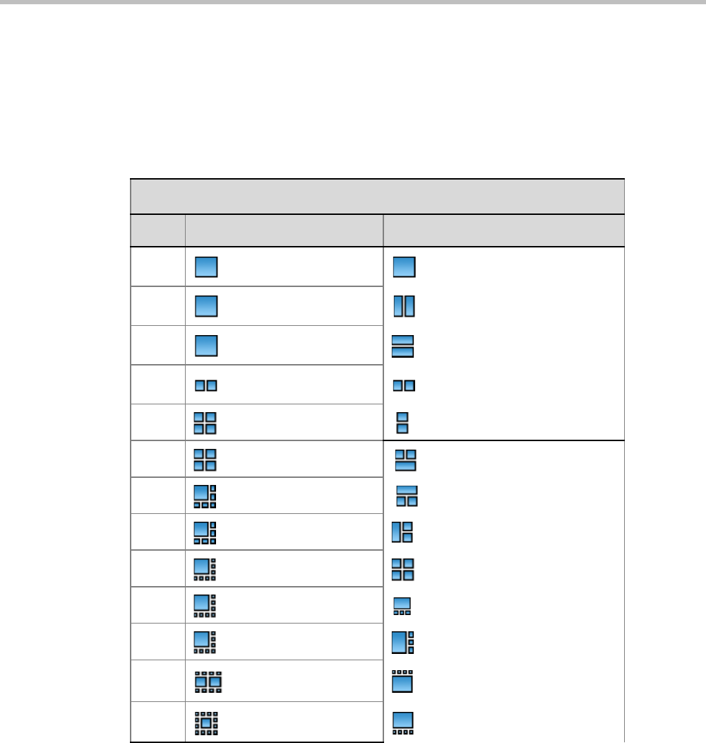
Chapter 20-System Configuration Flags
Polycom, Inc. 20-35
PREDEFINED_AUTO_LAYOUT_0, ... , PREDEFINED_AUTO_LAYOUT_12
Each of the 11 Auto Layout flags can be left at its default value, or set to any of the Possible
Values listed in Table 20-4.
The flag that controls the Auto Layout you wish to modify must be added to the System
Configuration file. For more information see "Modifying System Flags” on page 20-1.
Table 20-4 Flags: PREDEFINED_AUTO_LAYOUT_0,...,10
Flag Name: PREDEFINED_AUTO_LAYOUT_n (n = Number of Participants)
nDefault Value Possible Values
0 CP_LAYOUT_1X1 CP_LAYOUT_1X1
1 CP_LAYOUT_1X1 CP_LAYOUT_1X2
2 CP_LAYOUT_1X1 CP_LAYOUT_1X2HOR
3 CP_LAYOUT_1x2VER CP_LAYOUT_1X2VER
4 CP_LAYOUT_2X2 CP_LAYOUT_2X1
5 CP_LAYOUT_2X2 CP_LAYOUT_1P2HOR
6 CP_LAYOUT_1P5 CP_LAYOUT_1P2HOR_UP
7 CP_LAYOUT_1P5 CP_LAYOUT_1P2VER
8 CP_LAYOUT_1P7 CP_LAYOUT_2X2
9 CP_LAYOUT_1P7 CP_LAYOUT_1P3HOR_UP
10 CP_LAYOUT_1P7 CP_LAYOUT_1P3VER
11 CP_LAYOUT_2P8 CP_LAYOUT_1P4HOR
12 CP_LAYOUT_1P12 CP_LAYOUT_1P4HOR_UP
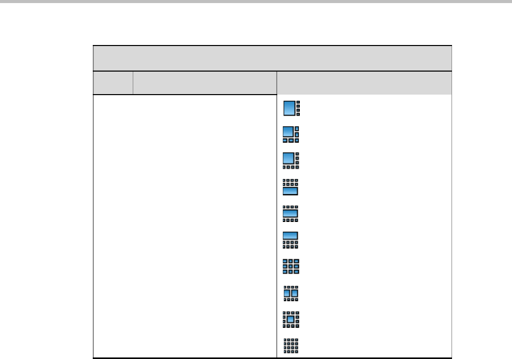
Polycom® RealPresence Collaboration ServerVirtual Edition Administrator’s Guide
20-36 Polycom, Inc.
CP_LAYOUT_1P4VER
CP_LAYOUT_1P5
CP_LAYOUT_1P7
CP_LAYOUT_1P8UP
CP_LAYOUT_1P8CENT
CP_LAYOUT_1P8HOR_UP
CP_LAYOUT_3X3
CP_LAYOUT_2P8
CP_LAYOUT_1P12
CP_LAYOUT_4X4
Table 20-4 Flags: PREDEFINED_AUTO_LAYOUT_0,...,10 (Continued)
Flag Name: PREDEFINED_AUTO_LAYOUT_n (n = Number of Participants)
nDefault Value Possible Values
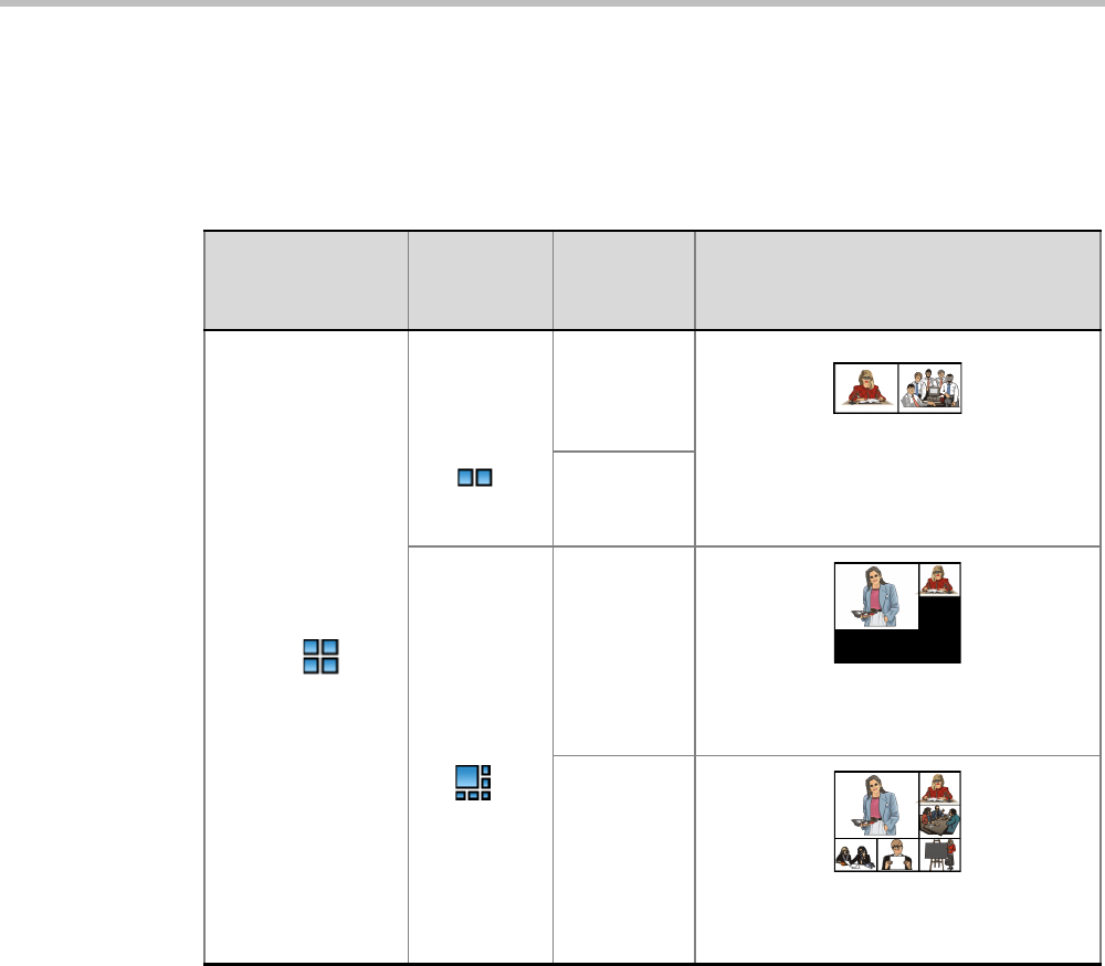
Chapter 20-System Configuration Flags
Polycom, Inc. 20-37
Example:
Table 20-5 illustrates the effect of modifying the PREDEFINED_AUTO_LAYOUT_5 flag in
conferences with fewer or more participants than the number of windows selected in the
default layout.
CS_ENABLE_EPC Flag
Endpoints that support People+ may require a different signaling (for example, FX
endpoints). For these endpoints, manually add the flag CS_ENABLE_EPC with the value
YES (default value is NO) to the CS_MODULE_PARAMETERS tab.
Automatic Password Generation Flags
The Collaboration Server can be configured to automatically generate conference and
chairperson passwords when the Conference Password and Chairperson Password fields are left
blank.
Table 20-5 Example: Modifying PREDEFINED_AUTO_LAYOUT_5 Flag
Flag
Set to
Possible
Value
Number of
Participants Participant’s View
PREDEFINED
_AUTO_LAYOUT_5
Default =
CP_LAYOUT
_1x2VER
3
Voice activated switching displays the
current speaker in the left window of the
video layout and only the two last speakers
are displayed.
7
CP_LAYOUT
_1P5
3
Voice activated switching displays the
current speaker in the large (top left)
window of the video layout.
7
Voice activated switching displays the
current speaker in the top left window of
the video layout.
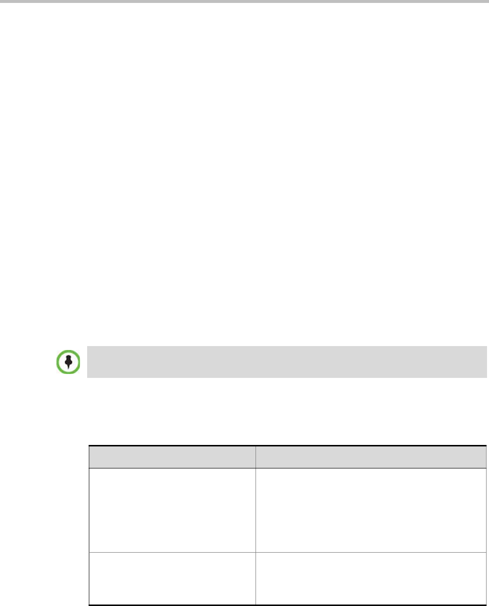
Polycom® RealPresence Collaboration ServerVirtual Edition Administrator’s Guide
20-38 Polycom, Inc.
Guidelines
•If the flag HIDE_CONFERENCE_PASSWORD is set to YES, the automatic generation
of passwords (both conference and chairperson passwords) is disabled, regardless of
the settings of the flags NUMERIC_CONF_PASS_DEFAULT_LEN and
NUMERIC_CHAIR_PASS_ DEFAULT _LEN.
• The automatic generation of conference passwords is enabled/disabled by the flag
NUMERIC_CONF_PASS_DEFAULT_LEN.
• The automatic generation of chairperson passwords is enabled/disabled by the flag
NUMERIC_CHAIR_PASS_ DEFAULT _LEN.
• The automatically generated passwords will be numeric and random.
• The passwords are automatically assigned to ongoing conferences, and Meeting Rooms
at the end of the creation process (once they are added to the Collaboration Server).
• Automatically assigned passwords can be manually changed through the Conference/
Meeting Room/Reservation Properties dialog boxes.
• Deleting an automatically created password will not cause the system to generate a new
password and the new password must be added manually or the field can be left blank.
• If a password was assigned to the conference via Microsoft Outlook using the PCO add-
in, the system does not change these passwords and additional passwords will not be
generated (for example, if only the conference password was assigned a chairperson
password will not be assigned).
• If the flag values (i.e. the password lengths) are changed, passwords that were already
assigned to conferencesand Meeting Rooms will not change and they can be activated
using the existing passwords. Only new conferencing entities will be affected by the
change.
Enabling the Automatic Generation of Passwords
To enable the automatic generation of passwords, the following flags have to be defined:
Do not enable this option in an environment that includes a Polycom DMA system.
Table 20-6 Automatic Password Generation Flags
Flag Description
HIDE_CONFERENCE_PASSWORD NO (default) - Conference and chairperson passwords
are displayed when viewing the Conference/Meeting
Room/ Reservation properties. It also enables the
automatic generation of passwords in general.
Yes - Conference and Chairperson Passwords are
hidden (they are replaced by asterisks). It also disables
the automatic generation of passwords.
NUMERIC_CONF_PASS_MIN_LEN Enter the minimum number of characters required for
conference passwords.
Possible values: 0 – 16.
0 (default) means no minimum length.

Chapter 20-System Configuration Flags
Polycom, Inc. 20-39
If the default password length defined by the NUMERIC_CONF_PASS_DEFAULT_LEN or
NUMERIC_CHAIR_PASS_ DEFAULT LEN does not fall within the range defined by the
minimum and maximum length an appropriate fault is added to the Faults list.
NUMERIC_CHAIR_PASS_MIN_LEN Enter the minimum number of characters required for
chairperson passwords.
Possible values: 0 – 16.
0 (default) means no minimum length. However this
setting cannot be applied when the Collaboration Server
is in Ultra Secure Mode.
NUMERIC_CONF_PASS_MAX_LEN Enter the maximum number of characters permitted for
conference passwords.
Possible values: 0 – 16
16 (default) - Conference password maximum length is
16 characters.
NUMERIC_CHAIR_PASS_MAX_LEN Enter the maximum number of characters permitted for
chairperson passwords.
Possible values: 0 – 16
16 (default) - chairperson password maximum length is
16 characters.
NUMERIC_CONF_PASS_DEFAULT_L
EN
This flag enables or disables the automatic generation of
conference passwords. The length of the automatically
generated passwords is determined by the flag value.
Possible values: 0 – 16, 6 default
Enter 0 to disable the automatic generation of
passwords.
Any value other than 0 enables the automatic generation
of conference passwords provided the flag
HIDE_CONFERENCE_PASSWORD is set to NO.
If the default is used, in non-secured mode the system
will automatically generate conference passwords that
contain 6 characters.
NUMERIC_CHAIR_PASS_ DEFAULT
_LEN
This flag enables or disables the automatic generation of
chairperson passwords. The length of the automatically
generated passwords is determined by the flag value.
Possible values: 0 – 16, 6 default
Enter 0 to disable the automatic generation of
passwords.
Any value other than 0 enables the automatic generation
of chairperson passwords provided the flag
HIDE_CONFERENCE_PASSWORD is set to NO.
If the default is used, in non-secured mode the system
will automatically generate chairperson passwords that
contain 6 characters.
Table 20-6 Automatic Password Generation Flags (Continued)
Flag Description

Polycom® RealPresence Collaboration ServerVirtual Edition Administrator’s Guide
20-40 Polycom, Inc.

Polycom, Inc. A-1
Appendix A
Disconnection Causes
If a participant was unable to connect to a conference or was disconnected from a conference,
the Connection Status tab in the Participant Properties dialog box indicates the call
disconnection cause. In some cases, a possible solution may be displayed.
A video participant who is unable to connect the video channels, but is able to connect as an
audio only participant, is referred to as a Secondary participant. For Secondary participants,
the Connection Status tab in the Participant Properties dialog box indicates the video
disconnection cause. In some cases, a possible solution may be indicated.
The table below lists the call disconnection causes that can be displayed in the Call
Disconnection Cause field and provides an explanation of each message
IP Disconnection Causes
Table A-1 Call Disconnection Causes
Disconnection Cause Description
Disconnected by User The user disconnected the endpoint from the
conference.
Remote device did not open the
encryption signaling channel
The endpoint did not open the encryption signaling
channel.
Remote devices selected encryption
algorithm does not match the local
selected encryption algorithm
The encryption algorithm selected by the endpoint does
not match the MCU's encryption algorithm.
Resources deficiency Insufficient resources available.
Call close. Call closed by MCU The MCU disconnected the call.
H323 call close. No port left for audio Insufficient audio ports.
H323 call close. No port left for video The required video ports exceed the number of ports
allocated to video in fixed ports.
H323 call close. No port left for FECC The required data ports exceed the number of ports
allocated to data in fixed ports.
H323 call close. No control port left The required control ports exceed the number of ports
allocated to control data in fixed ports.
H323 call close. No port left for videocont The required video content ports exceed the number of
ports allocated to video content in fixed ports.

Polycom® RealPresence Collaboration ServerVirtual Edition Administrator’s Guide
A-2 Polycom, Inc.
H323 call closed. Small bandwidth The gatekeeper allocated insufficient bandwidth to the
connection with the endpoint.
H323 call closed. No port left There are no free ports left in the IP card.
Caller not registered The calling endpoint is not registered in the gatekeeper.
H323 call closed. ARQ timeout The endpoint sent an ARQ message to the gatekeeper,
but the gatekeeper did not respond before timeout.
H323 call closed. DRQ timeout The endpoint sent a DRQ message to the gatekeeper,
but the gatekeeper did not respond before timeout.
H323 call closed. Alt Gatekeeper failure An alternate gatekeeper failure occurred.
H323 call closed. Gatekeeper failure A gatekeeper failure occurred.
H323 call closed. Remote busy The endpoint was busy. (Applicable only to dial-out)
H323 call closed. Normal The call ended normally, for example, the endpoint
disconnected.
H323 call closed. Remote reject The endpoint rejected the call.
H323 call closed. Remote unreachable The call remained idle for more than 30 seconds and
was disconnected because the destination device did
not answer. Possible causes can be due to network
problems, the gatekeeper could not find the endpoint's
address, or the endpoint was busy or unavailable (for
example, the “do not disturb” status is selected).
H323 call closed. Unknown reason The reason for the disconnection is unknown, for
example, the endpoint disconnected without giving a
reason.
H323 call closed. Faulty destination
address
Incorrect address format.
H323 call closed. Small bandwidth The gatekeeper allocated insufficient bandwidth to the
connection with the endpoint.
H323 call closed. Gatekeeper reject
ARQ
The gatekeeper rejected the endpoint's ARQ.
H323 call closed. No port left There are no ports left in the IP card.
H323 call closed. Gatekeeper DRQ The gatekeeper sent a DRQ.
H323 call closed. No destination IP
address
For internal use.
H323 call. Call failed prior or during the
capabilities negotiation stage
The endpoint did not send its capabilities to the
gatekeeper.
H323 call closed. Audio channels didn't
open before timeout
The endpoint did not open the audio channel.
Table A-1 Call Disconnection Causes (Continued)
Disconnection Cause Description

Appendix A-Disconnection Causes
Polycom, Inc. A-3
H323 call closed. Remote sent bad
capability
There was a problem in the capabilities sent by the
endpoint.
H323 call closed. Local capability wasn't
accepted by remote
The endpoint did not accept the capabilities sent by the
gatekeeper.
H323 failure Internal error occurred.
H323 call closed. Remote stop
responding
The endpoint stopped responding.
H323 call closed. Master slave problem A People + Content cascading failure occurred.
SIP bad name The conference name is incompatible with SIP
standards.
SIP bad status A general IP card error occurred.
SIP busy everywhere The participant's endpoints were contacted successfully,
but the participant is busy and does not wish to take the
call at this time.
SIP busy here The participant's endpoint was contacted successfully,
but the participant is currently not willing or able to take
additional calls.
SIP capabilities don't match The remote device capabilities are not compatible with
the conference settings.
SIP card rejected channels The IP card could not open the media channels.
SIP client error 400 The endpoint sent a SIP Client Error 400 (Bad Request)
response.
The request could not be understood due to malformed
syntax.
SIP client error 402 The endpoint sent a SIP Client Error 402 (Payment
Required) response.
SIP client error 405 The endpoint sent a SIP Client Error 405 (Method Not
Allowed) response.
The method specified in the Request-Line is understood,
but not allowed for the address identified by the
Request-URI.
SIP client error 406 The endpoint sent a SIP Client Error 406 (Not
Acceptable) resources.
The remote endpoint cannot accept the call because it
does not have the necessary responses. The resource
identified by the request is only capable of generating
response entities that have content characteristics not
acceptable according to the Accept header field sent in
the request.
Table A-1 Call Disconnection Causes (Continued)
Disconnection Cause Description

Polycom® RealPresence Collaboration ServerVirtual Edition Administrator’s Guide
A-4 Polycom, Inc.
SIP client error 407 The endpoint sent a SIP Client Error 407 (Proxy
Authentication Required) response.
The client must first authenticate itself with the proxy.
SIP client error 409 The endpoint sent a SIP Client Error 409 (Conflict)
response.
The request could not be completed due to a conflict
with the current state of the resource.
SIP client error 411 The endpoint sent a SIP Client Error 411 (Length
Required) response.
The server refuses to accept the request without a
defined Content Length.
SIP client error 413 The endpoint sent a SIP Client Error 413 (Request Entity
Too Large) response.
The server is refusing to process a request because the
request entity is larger than the server is willing or able
to process.
SIP client error 414 The endpoint sent a SIP Client Error 414 (Request-URI
Too Long) response.
The server is refusing to service the request because
the Request-URI is longer than the server is willing to
interpret.
SIP client error 420 The endpoint sent a SIP Client Error 420 (Bad
Extension) response.
The server did not understand the protocol extension
specified in a Require header field.
SIP client error 481 The endpoint sent a SIP Client Error 481 (Call/
Transaction Does Not Exist) response.
SIP client error 482 The endpoint sent a SIP Client Error 482 (Loop
Detected) response.
SIP client error 483 The endpoint sent a SIP Client Error 483 (Too Many
Hops) response.
SIP client error 484 The endpoint sent a SIP Client Error 484 (Address
Incomplete) response.
The server received a request with a To address or
Request-URI that was incomplete.
SIP client error 485 The endpoint sent a SIP Client Error 485 (Ambiguous)
response.
The address provided in the request (Request-URI) was
ambiguous.
SIP client error 488 The endpoint sent a SIP Client Error 488 (Not
Acceptable Here) response.
Table A-1 Call Disconnection Causes (Continued)
Disconnection Cause Description

Appendix A-Disconnection Causes
Polycom, Inc. A-5
SIP forbidden The SIP server rejected the request.
The server understood the request, but is refusing to
fulfill it.
SIP global failure 603 A SIP Global Failure 603 (Decline) response was
returned.
The participant's endpoint was successfully contacted,
but the participant explicitly does not wish to or cannot
participate.
SIP global failure 604 A SIP Global Failure 604 (Does Not Exist Anywhere)
response was returned.
The server has authoritative information that the user
indicated in the Request-URI does not exist anywhere.
SIP global failure 606 A SIP Global Failure 606 (Not Acceptable) response
was returned.
SIP gone The requested resource is no longer available at the
Server and no forwarding address is known.
SIP moved permanently The endpoint moved permanently. The user can no
longer be found at the address in the Request-URI.
SIP moved temporarily The remote endpoint moved temporarily.
SIP not found The endpoint was not found.
The server has definitive information that the user does
not exist at the domain specified in the Request-URI.
SIP redirection 300 A SIP Redirection 300 (Multiple Choices) response was
returned.
SIP redirection 305 A SIP Redirection 305 (Use Proxy) response was
returned.
The requested resource MUST be accessed through the
proxy given by the Contact field.
SIP redirection 380 A SIP Redirection 380 (Alternative Service) response
was returned.
The call was not successful, but alternative services are
possible.
SIP remote cancelled call The endpoint canceled the call.
SIP remote closed call The endpoint ended the call.
SIP remote stopped responding The endpoint is not responding.
SIP remote unreachable The endpoint could not be reached.
SIP request terminated The endpoint terminated the request.
The request was terminated by a BYE or CANCEL
request.
SIP request timeout The request was timed out.
Table A-1 Call Disconnection Causes (Continued)
Disconnection Cause Description

Polycom® RealPresence Collaboration ServerVirtual Edition Administrator’s Guide
A-6 Polycom, Inc.
SIP server error 500 The SIP server sent a SIP Server Error 500 (Server
Internal Error) response.
The server encountered an unexpected condition that
prevented it from fulfilling the request.
SIP server error 501 The SIP server sent a SIP Server Error 501 (Not
Implemented) response.
The server does not support the functionality required to
fulfill the request.
SIP server error 502 The SIP server sent a SIP Server Error 502 (Bad
Gateway) response.
The server, while acting as a gateway or proxy, received
an invalid response from the downstream server it
accessed in attempting to fulfill the request.
SIP server error 503 The SIP server sent a SIP Server Error 503 (Service
Unavailable) response.
The server is temporarily unable to process the request
due to a temporary overloading or maintenance of the
server.
SIP server error 504 The SIP server sent a SIP Server Error 504 (Server
Time-out) response.
The server did not receive a timely response from an
external server it accessed in attempting to process the
request.
SIP server error 505 The SIP server sent a SIP Server Error 505 (Version Not
Supported) response.
The server does not support, or refuses to support, the
SIP protocol version that was used in the request.
SIP temporarily not available The participant's endpoint was contacted successfully
but the participant is currently unavailable (e.g., not
logged in or logged in such a manner as to preclude
communication with the participant).
SIP remote device did not respond in the
given time frame
The endpoint did not respond in the given time frame.
SIP trans error TCP Invite A SIP Invite was sent via TCP, but the endpoint was not
found.
SIP transport error Unable to initiate connection with the endpoint.
SIP unauthorized The request requires user authentication.
SIP unsupported media type The server is refusing to service the request because
the message body of the request is in a format not
supported by the requested resource for the requested
method.
Table A-1 Call Disconnection Causes (Continued)
Disconnection Cause Description

Polycom, Inc. B-1
Appendix B
Active Alarms
Table B-1 Active Alarms
Alarm Code Alarm Description
A matching activation key is required. To
cancel the upgrade process, reset the
Collaboration Server
The system upgrade requires that a valid activation key be entered. If none is
available, resetting the Collaboration Server will cancel the upgrade and return
the Collaboration Server to the previous version.
A new activation key was loaded. Reset
the system.
A new activation key was loaded:
Reset the MCU.
A new version was installed. Reset the
system.
A new version was installed:
Reset the MCU.
Alarm generated by a Central Signaling
component
A system alert was generated by a component of the Central Signaling.
Alarm generated by an internal
component
A system alert was generated by an internal system component.
Allocation mode was modified
Automatic reset is unavailable in Safe
Mode
The system switches to safe mode if many resets occur during startup. To
prevent additional resets, and allow the system to complete the startup
process the automatic system resets are blocked.
Backup of audit files is required If the ENABLE_CYCLIC_FILE_SYSTEM_ALARMS is set to YES and a Cyclic
File reaches a file retention time or file storage capacity limit, the user is
alerted that audit files need to be backed up.
Backup of CDR files is required If the ENABLE_CYCLIC_FILE_SYSTEM_ALARMS is set to YES and a Cyclic
File reaches a file retention time or file storage capacity limit, the user is
alerted that CDR files need to be backed up.
Backup of log files is required If the ENABLE_CYCLIC_FILE_SYSTEM_ALARMS is set to YES and a Cyclic
File reaches a file retention time or file storage capacity limit, the user is
alerted that log files need to be backed up.
Central signaling component failure Possible explanations:
•Central signaling component failure; unit type:
[NonComponent\CSMngnt\CSH323\CSSIP]
•Central signaling component failure; unit type: (invalid:
[NonComponent\CSMngnt\CSH323\CSSIP])
•Central signaling component failure - Invalid failure type. Unit id: [id], Type:
[NonComponent\CSMngnt\CSH323\CSSIP], Status:
[Ok\Failed\Recovered]
•Central signaling component failure - Invalid failure type
Central Signaling indicating Faulty status Central signaling failure detected in IP Network Service.

RealPresence Collaboration Server Virtual Edition Administrator’s Guide
B-2 Polycom, Inc.
Central Signaling indicating Recovery
status
Central Signaling startup failure Central Signaling component is down.
Conference Encryption Error
Configuration of external database did not
complete.
Check the configuration of the external DB.
CPU IPMC software was not updated. Turn off the MCU and then turn it on.
CPU slot ID not identified The CPU slot ID required for Ethernet Settings was not provided by the Shelf
Management.
D channel cannot be established
DEBUG mode enabled Possible explanations:
•System is running in DEBUG mode.
•System DEBUG mode initiated.
In this mode, additional prints are added and Startup and Recovery Conditions
are different then Non Debug Mode.
Change the DEBUG_MODE flag value to NO and reset the Collaboration
Server.
DEBUG mode flags in use The system is using the DEBUG CFG flags.
DMA not supported by IDE device Possible explanations:
•DMA (direct memory access) not supported by IDE device: Incompatible
flash card / hard disk being used.
•Flash card / hard drive are not properly connected to the board / one of the
IDE channels is disconnected.
•DMA was manually disabled for testing.
DNS configuration error Check the DNS configuration.
DNS not configured in IP Network Service Configure the DNS in the IP Network Services.
Encryption Server Error. Failed to
generate the encryption key
FIPS 140 test failed while generating the new encryption key.
Error in external database certificate
Error reading MCU time Failed to read MCU time configuration file ([status]).
Manually configure the MCU Time in the Collaboration Server Web Client or
RMX Manager Manager application.
eUserMsgCode_Cs_EdgeServerDnsFaile
d
eUserMsgCode_Cs_SipTLS_CertificateH
asExpired
eUserMsgCode_Cs_SipTLS_CertificateS
ubjNameIsNotValid_Or_DnsFailed
Table B-1 Active Alarms (Continued)
Alarm Code Alarm Description

Appendix B-Active Alarms
Polycom, Inc. B-3
eUserMsgCode_Cs_SipTLS_Certificate
WillExpireInLessThanAWeek
eUserMsgCode_Cs_SipTLS_FailedToLo
adOrVerifyCertificateFiles
eUserMsgCode_Cs_SipTLS_Registration
HandshakeFailure
eUserMsgCode_Cs_SipTLS_Registration
ServerNotResponding
Event Mode Conferencing resources
deficiency due to inappropriate license.
Please install a new license
External NTP servers failure The MCU could not connect to any of the defined NTP server for
synchronization due to the remote server error or network error or
configuration error.
Change the configuration of the NTP server.
Failed to access DNS server Failed to access DNS server.
Failed to configure the Media card IP
address
Possible reasons for the failure:
•Failure type: [OK Or Not supported.
•Does not exist Or IP failure.
•Duplicate IP Or DHCP failure.
•VLAN failure Or Invalid: [status_Number].
Failed to configure the Users list in Linux The authentication process did not start.
Use the Restore to factory Defaults to recover.
Failed to connect to application server Possible reasons for the failure:
•Failed to connect to application server:
•Failed to establish connection to server, url = [url].
Failed to connect to recording device The MCU could not connect to the defined recording device due to
configuration error or network error.
Failed to connect to SIP registrar Cannot establish connection with SIP registrar.
Failed to create Default Profile Possible reasons for the failure:
•Failed to validate the default Profile.
•Failed to add the default Profile.
Possible action:
•Restore the Collaboration Server configuration from the Backup.
•Use the Non-Comprehensive Restore To Factory Defaults operation.
Failed to initialize system base mode
Table B-1 Active Alarms (Continued)
Alarm Code Alarm Description

RealPresence Collaboration Server Virtual Edition Administrator’s Guide
B-4 Polycom, Inc.
Failed to initialize the file system Possible reasons for the failure:
•Failed to initialize the file system.
•Failed to initialize the file system and create the CDR index.
Reset the MCU.
Failed to open Users list file Restore the MCU configuration or re-define the user.
Failed to register with DNS server Check the DNS configuration.
Failed to subscribe with the OCS,
therefore the A/V Edge Server URI was
not received
Failure in initialization of SNMP agent.
Fallback version is being used Fallback version is being used. Restore current version.
Version being used: [running version]; Current version: [current version].
Fan Problem Level Critical
Fan Problem Level Major
File error Possible reasons for the file error:
•XML file does not exist [file name]; Error no: [error number].
•Not authorized to open XML file [file name]; Error no: [error number].
•Unknown problem in opening XML file [file name]; Error no: [error number].
•Failed to parse XML file [file name].
File system scan failure File system scan failure: Failed to scan [file system path].
Multiple occurrences may point to a hardware problem.
System is functioning.
File system space shortage File system space shortage:
Out of file system space in [file system path]; Free space: [free space
percentage]% ([free space] Blocks) - Minimum free space required: [minimum
free space percentage]% ([minimum free space] Blocks).
FIPS 140 failure
FIPS 140 test result not received
Table B-1 Active Alarms (Continued)
Alarm Code Alarm Description

Appendix B-Active Alarms
Polycom, Inc. B-5
Gatekeeper failure Possible reasons for the Gatekeeper failure:
•Failed to register to alternate Gatekeeper.
•Gatekeeper discovery state.
- Check GK IP address (GUI, ping)
•Gatekeeper DNS Host name not found.
•Gatekeeper Registration Timeout.
•Gatekeeper rejected GRQ due to invalid revision.
•Gatekeeper rejected GRQ due to resource unavailability.
•Gatekeeper rejected GRQ due to Terminal Exclusion.
•Gatekeeper rejected GRQ due to unsupported feature.
•Gatekeeper rejected GRQ. Reason 18.
•Gatekeeper rejected RRQ due to Discovery Required.
•Gatekeeper rejected RRQ due to duplicate alias.
- Check duplicate in aliases or in prefixes
•Gatekeeper rejected RRQ due to Generic Data.
•Gatekeeper rejected RRQ due to invalid alias.
•Gatekeeper rejected RRQ due to invalid call signaling address.
•Gatekeeper rejected RRQ due to invalid endpoint ID.
•Gatekeeper rejected RRQ due to invalid RAS address.
•Gatekeeper rejected RRQ due to invalid revision.
•Gatekeeper rejected RRQ due to invalid state.
•Gatekeeper rejected RRQ due to invalid terminal alias.
•Gatekeeper rejected RRQ due to resource unavailability.
•Gatekeeper rejected RRQ due to Security Denial.
•Gatekeeper rejected RRQ due to terminal type.
•Gatekeeper rejected RRQ due to unsupported Additive Registration.
•Gatekeeper rejected RRQ due to unsupported feature.
•Gatekeeper rejected RRQ due to unsupported QOS transport.
•Gatekeeper rejected RRQ due to unsupported transport.
•Gatekeeper rejected RRQ. Full registration required.
•Gatekeeper rejected RRQ. Reason 18.
•Gatekeeper Unregistration State.
•Registration succeeded.
Check the Gatekeeper configuration.
GUI System configuration file is invalid
xml file
The XML format of the system configuration file that contains the user interface
settings is invalid.
Hard disk error Hard disk not responding.
Hot Backup: Master-Slave configuration
conflict.
Possible reasons:
• When both the MCUs are configured as Master or as Slave
• The slave Collaboration Server is defined with the same IP as the Master.
Hot backup: Network issue
Table B-1 Active Alarms (Continued)
Alarm Code Alarm Description

RealPresence Collaboration Server Virtual Edition Administrator’s Guide
B-6 Polycom, Inc.
Hot Backup: Paired MCU is unreachable.
Initialization of ice stack failed
Insufficient resources The number of resources in the license is higher than the actual system
resources.
Check to make sure sufficient CPU cores are allocated in the Virtual Machine.
Insufficient UDP Ports When defining fixed port, the number of defined UDP ports is lower than the
required ports.
Configure additional ports.
Internal System configuration during
startup
System configuration during startup.
Wait until Collaboration Server startup is completed.
Invalid System Configuration
IP addresses of Signaling Host and
Control Unit are the same
IP addresses of Signaling Host and Control Unit are identical.
Assign different IP addresses to the Signaling Host and Control Unit.
IP Network Service added
IP Network Service configuration modified IP Network Service was modified.
Reset the MCU.
IP Network Service deleted IP Network Service was deleted.
Reset the MCU.
IP Network Service not found IP Service not found in the Network Services list.
Configure the IP Network Service.
IPMC software upgrade in component
IPS 140 test result not received
LDAP TLS: Failed to connect to OSCP
responder
License not found Possible causes:
•The Central Signaling component could not find the IP Services after
startup.
•During Startup, the resources did not get the License required to utilize
their Units.
Possible action:
•Configure IP service if not configured.
•Reset the MCU.
•Change the license
Management Network not configured Configure the Management Network.
Missing Central Signaling configuration Configure the central signaling.
Missing Central Signaling IP configuration
Table B-1 Active Alarms (Continued)
Alarm Code Alarm Description

Appendix B-Active Alarms
Polycom, Inc. B-7
MPL startup failure. Authentication not
received.
Authentication was not received from Switch.
Check the switch card.
MPL startup failure. Management
Network configuration not received.
Management Network message was not received.
Check the Switch card.
Network interface is not configured. New
interface need to be chosen
Network traffic capture is on
New certificate for CS need Collaboration
Server reset to take effect
No default IVR Service in IVR Services
list
No default IVR Service in IVR Services list.
Ensure that one conference IVR Service and one EQ IVR Service are set as
default.
No IP Network Services defined IP Network Service parameters missing.
Configure the IP Network Service.
No LAN connection
No response from Central Signaling No connection with central signaling.
No RTM-LAN or RTM-ISDN installed.
One of these cards must be installed in
the RealPresence Collaboration Server
(RMX) 4000
No usable unit for audio controller No media card is installed, or the media card installed is not functioning.
Install the appropriate media card.
OCS Registration failed
Password expiration warning
Please install a newer version
Port configuration was modified
Power off
Power Problem Level Critical
Power Problem Level Major
Product activation failure Assign a new activation key.
Product Type mismatch. System is
restarting.
The user is alerted to a mismatch between the product type that is stored in
MCU software and the product type received from another system component.
In such a case the system is automatically restarted.
Received Notification failed
Recording device has disconnected
unexpectedly
Table B-1 Active Alarms (Continued)
Alarm Code Alarm Description

RealPresence Collaboration Server Virtual Edition Administrator’s Guide
B-8 Polycom, Inc.
Requested changes to the certification
repository were not completed.
Repository must be updated to implement
these changes.
Resource process failed to request the
Meeting Room list during startup.
Without the Meeting Rooms list, the system cannot allocate the appropriate
dial numbers, Conference ID etc. and therefore cannot run conferences.
Restore Failed Restoring the system configuration has failed as the system could not locate
the configuration file in the selected path, or could not open the file.
Restore Succeeded Restoring the system configuration has succeeded. Reset the MCU.
Restoring Factory Defaults. Default
system settings will be restored once
Reset is completed
Default system settings will be restored once Reset is completed.
Collaboration Server fails to connect to
Active Directory server.
Collaboration Server is uploading the
version file. To cancel the upload and the
upgrade, reset the Collaboration Server
Collaboration Server user/password list
will be reset
Secured SIP communication failed Error status (408) received from SIP proxy.
Security mode failed. Certificate has
expired.
Security mode failed. Certificate host
name does not match the Collaboration
Server host name.
Security mode failed. Certificate is about
to expire.
Security mode failed. Certificate not yet
valid.
Security mode failed. Error in certificate
file.
Service Request failed
SIP registrations limit reached SIP registrations limit reached.
SIP TLS: Certificate has expired The current TLS certificate files have expired and must be replaced with new
files.
SIP TLS: Certificate is about to expire The current TLS certificate files will expire shortly and will have to be replaced
to ensure the communication with the OCS.
SIP TLS: Certificate subject name is not
valid or DNS failed to resolve this name
This alarm is displayed if the name of the Collaboration Server in the certificate
file is different from the FQDN name defined in the OCS.
Table B-1 Active Alarms (Continued)
Alarm Code Alarm Description

Appendix B-Active Alarms
Polycom, Inc. B-9
SIP TLS: Failed to load or verify certificate
files
This alarm indicates that the certificate files required for SIP TLS could not be
loaded to the Collaboration Server. Possible causes are:
•Incorrect certificate file name. Only files with the following names can be
loaded to the system: rootCA.pem, pkey.pem, cert.pem and
certPassword.txt
•Wrong certificate file type. Only files of the following types can be loaded to
the system: rootCA.pem, pkey.pem and cert.pem and certPassword.txt
•The contents of the certificate file does not match the system parameters
SIP TLS: Registration handshake failure This alarm indicates a mismatch between the security protocols of the OCS
and the Collaboration Server, preventing the Registration of the Collaboration
Server to the OCS.
SIP TLS: Registration server not
responding
This alarm is displayed when the Collaboration Server does not receive a
response from the OCS to the registration request in the expected time frame.
Possible causes are:
•The Collaboration Server FQDN name is not defined in the OCS pool, or is
defined incorrectly.
•The time frame for the expected response was too short and it will be
updated with the next data refresh. The alarm may be cleared
automatically the next time the data is refreshed.
•The Collaboration Server FQDN name is not defined in the DNS server.
Ping the DNS using the Collaboration Server FQDN name to ensure that
the Collaboration Server is correctly registered to the DNS.
SIP TLS: Registration transport error This alarm indicates that the communication with the SIP server cannot be
established. Possible causes are:
•Incorrect IP address of the SIP server
•The SIP server listening port is other than the one defined in the system
•The OCS services are stopped
Software upgrade in component
SSH is enabled
SWITCH not responding Check the Switch card.
System Cards MPM Plus mode are not
supported in Event mode
System configuration changed. Please
reset the MCU
System Configuration modified System configuration flags were modified.
Reset the MCU.
System resources of Audio ports usage
has exceeded Port Gauge threshold
System resources of Video ports usage
has exceeded Port Gauge threshold
Table B-1 Active Alarms (Continued)
Alarm Code Alarm Description

RealPresence Collaboration Server Virtual Edition Administrator’s Guide
B-10 Polycom, Inc.
System resources usage has exceeded
Port Gauge threshold
Temperature Level - Critical Possible explanations:
•Temperature has reached a critical level.
Temperature Level - Major Possible explanations:
•Temperature has reached a problematic level and requires attention.
The Log file system is disabled because
of high system CPU usage
The MCCF channel is not connected
The software contains patch(es) The software contains patch(es).
Unable to connect to Exchange Server.
User Name SUPPORT cannot be used in
Enhanced Security Mode
Version upgrade is in progress
Voltage problem Possible reasons for the problem:
•Card voltage problem.
•Voltage problem
Warning: Upgrade started and SAFE
Upgrade protection is turned OFF
Yellow Alarm Problem sending/receiving data from/to network.
Check the cables.
Table B-1 Active Alarms (Continued)
Alarm Code Alarm Description

Polycom, Inc. C-1
Appendix C
CDR Fields - Unformatted File
The CDR (Call Detail Records) utility is used to retrieve conference information to a file. The
CDR utility can retrieve conference information to a file in both formatted and unformatted
formats.
Unformatted CDR files contain multiple records. The first record in each file contains
information about the conference in general, such as the conference name and start time. The
remaining records each contain information about one event that occurred during the
conference, such as a participant connecting to the conference, or a user extending the length
of the conference. The first field in each record identifies the event type, and this is followed
by values containing information about the event. The fields are separated by commas.
Formatted files contain basically the same information as unformatted files, but with the
field values replaced by descriptions. Formatted files are divided into sections, each
containing information about one conference event. The first line in each section is a title
describing the type of event, and this is followed by multiple lines, each containing
information about the event in the form of a descriptive field name and value.
The MCU sends the entire CDR file via API or HTTP, and the Collaboration Server or
external application does the processing and sorting. The Collaboration Server ignores
events that it does not recognize, that is, events written in a higher version that do not exist in
the current version. Therefore, to enable compatibility between versions, instead of adding
new fields to existing events, new fields are added as separate events, so as not to affect the
events from older versions. This allows users with lower versions to retrieve CDR files that
were created in higher versions.
The field names and values in the formatted file will appear in the language being used for the
Collaboration Server Web Client user interface at the time when the CDR information is retrieved.
The value of the fields that support Unicode values, such as the info fields, will be stored in the CDR
file in UTF8. The application that reads the CDR file must support Unicode.
This appendix describes the fields and values in the unformatted CDR records.
Although the formatted files contain basically the same information, in a few instances a single field in
the unformatted file is converted to multiple lines in the formatted file, and in other cases, multiple
fields in the unformatted file are combined into one line in the formatted file.
In addition, to enable compatibility for applications that were written for the MGC family, the
unformatted file contains fields that were supported by the MGC family, but are not supported by the
Collaboration Server, whereas these fields are omitted from the formatted file.

RealPresence Collaboration Server Virtual Edition Administrator’s Guide
C-2 Polycom, Inc.
The Conference Summary Record
The conference summary record (the first record in the unformatted CDR file) contains the
following fields:
Table C-1 Conference Summary Record Fields
Field Description
File Version The version of the CDR utility that created the file.
Conference Routing
Name
The Routing Name of the conference.
Internal Conference ID The conference identification number as assigned by the system.
Reserved Start Time The time the conference was scheduled to start in Greenwich Mean Time
(GMT). The reservation time of a reservation that was started
immediately or of an ongoing conference is the same as the Actual Start
Time.
Reserved Duration The amount of time the conference was scheduled to last.
Actual Start Time The actual time the conference started in GMT.
Actual Duration The actual conference duration.
Status The conference status code as follows:
1 - The conference is an ongoing conference.
2 - The conference was terminated by a user.
3 - The conference ended at the scheduled end time.
4 - The conference ended automatically because no participants joined
the conference for a predefined time period, or all the participants
disconnected from the conference and the conference was empty for a
predefined time period.
5 - The conference never started.
6 - The conference could not start due to a problem.
8 - An unknown error occurred.
9 - The conference was terminated by a participant using DTMF codes.
Note: If the conference was terminated by an MCU reset, this field will
contain the value 1 (ongoing conference).
File Name The name of the conference log file.
GMT Offset Sign Indicates whether the GMT Offset is positive or negative. The possible
values are:
0 - Offset is negative. GMT Offset will be subtracted from the GMT Time.
1 - Offset is positive. GMT Offset will be added to the GMT Time.
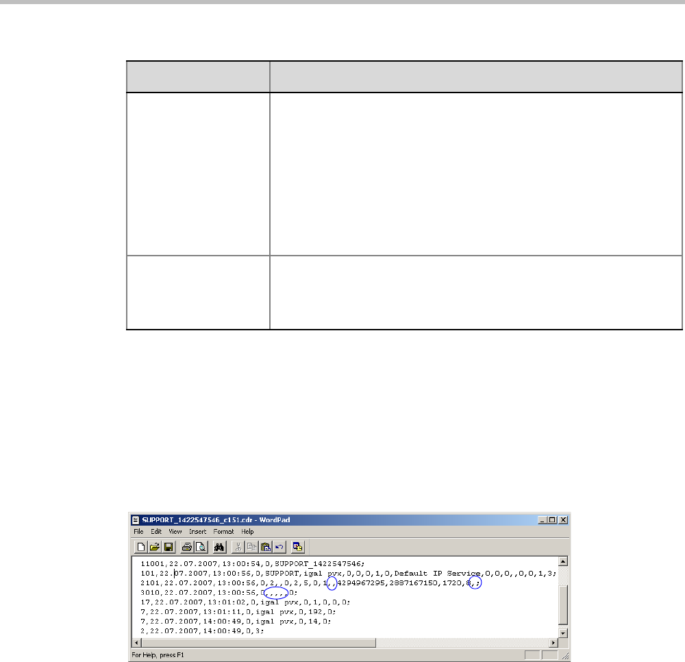
Appendix C-CDR Fields - Unformatted File
Polycom, Inc. C-3
Event Records
The event records, that is, all records in the unformatted file except the first record, contain
standard fields, such as the event type code and the time stamp, followed by fields that are
event specific.
The event fields are separated by commas. Two consecutive commas with nothing between
them (,,), or a comma followed immediately by a semi-colon (,;), indicates an empty field, as
in the example below:
Standard Event Record Fields
All event records start with the following fields:
• The CDR event type code. For a list of event type codes and descriptions, refer to
Table C-2, “CDR Event Types,” on page C-4.
• The event date.
• The event time.
• The structure length. This field is required for compatibility purposes, and always
contains the value 0.
GMT Offset The time zone difference between Greenwich and the Collaboration
Server’s physical location in hours and minutes.
Together with the GMT Offset Sign field the GMT Offset field is used to
define the Collaboration Server local time. For example, if the GMT
Offset Sign is 0 and GMT Offset is 3 hours then the time zone of the
Collaboration Server’s physical location is -3, which will be subtracted
from the GMT time to determine the local time. However, if the GMT
Offset Sign is 1 and GMT Offset is 4 hours then the time zone of the
Collaboration Server’s physical location is +4, which will be added to the
GMT time to determine the local time.
File Retrieved Indicates if the file has been retrieved and saved to a formatted file, as
follows:
0 - No
1 - Yes
Table C-1 Conference Summary Record Fields (Continued)
Field Description

RealPresence Collaboration Server Virtual Edition Administrator’s Guide
C-4 Polycom, Inc.
Event Types
The table below contains a list of the events that can be logged in the CDR file, and indicates
where to find details of the fields that are specific to that type of event.
The event code identifies the event in the unformatted CDR file, and the event name identifies the
event in the formatted CDR file.
Table C-2 CDR Event Types
Event Code Event Name Description
1CONFERENCE
START
The conference started.
For more information about the fields, see Table C-3, “Event
Fields for Event 1 - CONFERENCE START,” on page C-10.
Note: There is one CONFERENCE START event per
conference. It is always the first event in the file, after the
conference summary record. It contains conference details,
but not participant details.
2CONFERENCE
END
The conference ended.
For more information about the fields, see Table C-8, “Event
Fields for Event 2 - CONFERENCE END,” on page C-15.
Note: There is one CONFERENCE END event per
conference, and it is always the last event in the file.
7PARTICIPANT
DISCONNECTED
A participant disconnected from the conference.
For more information about the fields, see Table C-11, “Event
Fields for Event 7 - PARTICIPANT DISCONNECTED,” on
page C-15.
10 DEFINED
PARTICIPANT
Information about a defined participant, that is, a participant
who was added to the conference before the conference
started.
For more information about the fields, see Table C-13, “Event
Fields for Events 10, 101, 105 - DEFINED PARTICIPANT,
USER ADD PARTICIPANT, USER UPDATE PARTICIPANT,”
on page C-16.
Note: There is one event for each participant defined before
the conference started.
15 H323 CALL
SETUP
Information about the IP address of the participant.
For more information about the fields, see Table C-16, “Event
fields for Event 15 - H323 CALL SETUP,” on page C-19.
17 H323
PARTICIPANT
CONNECTED
An H.323 participant connected to the conference.
For more information about the fields, see Table C-17, “Event
Fields for Events 17, 23 - H323 PARTICIPANT CONNECTED,
SIP PARTICIPANT CONNECTED,” on page C-20.

Appendix C-CDR Fields - Unformatted File
Polycom, Inc. C-5
18 NEW
UNDEFINED
PARTICIPANT
A new undefined participant joined the conference.
For more information about the fields, see Table C-18, “Event
Fields for Event 18 - NEW UNDEFINED PARTICIPANT,” on
page C-22.
20 BILLING CODE A billing code was entered by a participant using DTMF codes.
For more information about the fields, see Table C-20, “Event
Fields for Event 20 - BILLING CODE,” on page C-24.
21 SET
PARTICIPANT
DISPLAY NAME
A user assigned a new name to a participant, or an end point
sent its name.
For more information about the fields, see Table C-21, “Event
Fields for Event 21 - SET PARTICIPANT DISPLAY NAME,” on
page C-25.
22 DTMF CODE
FAILURE
An error occurred when a participant entered a DTMF code.
For more information about the fields, see Table C-22, “Event
Fields for Event 22 - DTMF CODE FAILURE,” on page C-25.
23 SIP
PARTICIPANT
CONNECTED
A SIP participant connected to the conference.
For more information about the fields, see Table C-17, “Event
Fields for Events 17, 23 - H323 PARTICIPANT CONNECTED,
SIP PARTICIPANT CONNECTED,” on page C-20.
26 RECORDING
LINK
A recording event, such as recording started or recording
resumed, occurred.
For more information about the fields, see Table C-23, “Event
fields for Event 26 - RECORDING LINK,” on page C-25.
28 SIP PRIVATE
EXTENSIONS
Contains SIP Private Extensions information.
For more information about the fields, see Table C-24, “Event
Fields for Event 28 - SIP PRIVATE EXTENSIONS,” on
page C-26.
30 GATEKEEPER
INFORMATION
Contains the gatekeeper caller ID, which makes it possible to
match the CDR in the gatekeeper and in the MCU.
For more information about the fields, see Table C-25, “Event
Fields for Event 30 - GATEKEEPER INFORMATION,” on
page C-26.
31 PARTICIPANT
CONNECTION
RATE
Information about the line rate of the participant connection.
This event is added to the CDR file each time the endpoint
changes its connection bit rate. For more information about the
fields, see Table C-26, “Event fields for Event 31 -
PARTICIPANT CONNECTION RATE,” on page C-26.
Table C-2 CDR Event Types (Continued)
Event Code Event Name Description

RealPresence Collaboration Server Virtual Edition Administrator’s Guide
C-6 Polycom, Inc.
33 PARTY CHAIR
UPDATE
Participants connect to the conferences as standard
participants and they are designated as chairpersons either by
entering the chairperson password during the IVR session
upon connection, or while participating in the conference using
the appropriate DTM code.
For more information about the fields, see see “Event fields for
Event 33 - PARTY CHAIR UPDATE” on page C-27.
34 PARTICIPANT
MAXIMUM
USAGE
INFORMATION
This event includes information of the maximum line rate,
maximum resolution and maximum frame rate used by H.323
or SIP participant during the conference.
35 SVC SIP
PARTICIPANT
CONNECTED
An SVC user connected over SIP.
For more information about the fields, see Table C-30, “Event
Fields for Event 35 - SVC SIP PARTICIPANT CONNECTED,”
on page C-27.
100 USER
TERMINATE
CONFERENCE
A user terminated the conference.
For more information about the fields, see Table C-31, “Event
Fields for Event 100 - USER TERMINATE CONFERENCE,”
on page C-28.
101 USER ADD
PARTICIPANT
A user added a participant to the conference during the
conference.
For more information about the fields, see Table C-13, “Event
Fields for Events 10, 101, 105 - DEFINED PARTICIPANT,
USER ADD PARTICIPANT, USER UPDATE PARTICIPANT,”
on page C-16.
102 USER DELETE
PARTICIPANT
A user deleted a participant from the conference.
For more information about the fields, see Table C-32, “Event
Fields for Events 102,103, 104 - USER DELETE
PARTICIPANT, USER DISCONNECT PARTICIPANT, USER
RECONNECT PARTICIPANT,” on page C-28.
103 USER
DISCONNECT
PARTICIPANT
A user disconnected a participant.
For more information about the fields, see Table C-32, “Event
Fields for Events 102,103, 104 - USER DELETE
PARTICIPANT, USER DISCONNECT PARTICIPANT, USER
RECONNECT PARTICIPANT,” on page C-28.
104 USER
RECONNECT
PARTICIPANT
A user reconnected a participant who was disconnected from
the conference.
For more information about the fields, see Table C-32, “Event
Fields for Events 102,103, 104 - USER DELETE
PARTICIPANT, USER DISCONNECT PARTICIPANT, USER
RECONNECT PARTICIPANT,” on page C-28.
Table C-2 CDR Event Types (Continued)
Event Code Event Name Description

Appendix C-CDR Fields - Unformatted File
Polycom, Inc. C-7
105 USER UPDATE
PARTICIPANT
A user updated the properties of a participant during the
conference.
For more information about the fields, see Table C-13, “Event
Fields for Events 10, 101, 105 - DEFINED PARTICIPANT,
USER ADD PARTICIPANT, USER UPDATE PARTICIPANT,”
on page C-16.
106 USER SET END
TIME
A user modified the conference end time.
For more information about the fields, see Table C-33, “Event
Fields for Event 106 - USER SET END TIME,” on page C-29.
107 OPERATOR
MOVE PARTY
FROM
CONFERENCE
The participant moved from an Entry Queue to the destination
conference or between conferences.
For more information about the fields, see Table C-34, “Event
Fields for Events 107 and 109 - OPERATOR MOVE PARTY
FROM CONFERENCE and OPERATOR ATTEND PARTY,” on
page C-29.
108 OPERATOR
MOVE PARTY
TO
CONFERENCE
The Collaboration Server User moved the participant from an
ongoing conference to another conference.
For more information, see Table C-35, “Event Fields for
Events 108, 112 - OPERATOR MOVE PARTY TO
CONFERENCE, OPERATOR ATTEND PARTY TO
CONFERENCE,” on page C-29.
109 OPERATOR
ATTEND PARTY
The Collaboration Server User moved the participant to the
Operator conference.
For more information, see Table C-34, “Event Fields for Events
107 and 109 - OPERATOR MOVE PARTY FROM
CONFERENCE and OPERATOR ATTEND PARTY,” on
page C-29.
111 OPERATOR
BACK TO
CONFERENCE
PARTY
The Collaboration Server User moved the participant back to
his Home (source) conference.
For more information, see Table C-36, “Event Fields for Event
111 - OPERATOR BACK TO CONFERENCE PARTY,” on
page C-33.
112 OPERATOR
ATTEND PARTY
TO
CONFERENCE
The Collaboration Server User moved the participant from the
Operator conference to another conference.
For more information, see Table C-35, “Event Fields for
Events 108, 112 - OPERATOR MOVE PARTY TO
CONFERENCE, OPERATOR ATTEND PARTY TO
CONFERENCE,” on page C-29.
1001 NEW
UNDEFINED
PARTICIPANT
CONTINUE 1
Additional information about a NEW UNDEFINED
PARTICIPANT event.
For more information about the fields, see Table C-19, “Event
Fields for Event 1001 - NEW UNDEFINED PARTY
CONTINUE 1,” on page C-24.
Table C-2 CDR Event Types (Continued)
Event Code Event Name Description

RealPresence Collaboration Server Virtual Edition Administrator’s Guide
C-8 Polycom, Inc.
2001 CONFERENCE
START
CONTINUE 1
Additional information about a CONFERENCE START event.
For more information about the fields, see Table C-4, “Event
Fields for Event 2001 - CONFERENCE START CONTINUE 1,”
on page C-11.
2007 PARTICIPANT
DISCONNECTED
CONTINUE 1
Additional information about a PARTICIPANT
DISCONNECTED event.
For more information about the fields, see Table C-12, “Event
Fields for Event 2007 - PARTICIPANT DISCONNECTED
CONTINUE 1,” on page C-15.
2010 DEFINED
PARTICIPANT
CONTINUE 1
Additional information about a DEFINED PARTICIPANT event.
For more information about the fields, see Table C-14, “Event
Fields for Events 2010, 2011, 2015 - DEFINED PARTICIPANT
CONTINUE 1, USER ADD PARTICIPANT CONTINUE 1,
USER UPDATE PARTICIPANT CONTINUE 1,” on page C-18.
2011 RESERVED
PARTICIPANT
CONTINUE PV6
ADDRESS
Additional information about a DEFINED PARTICIPANT event
that includes the IPv6 addressing of the defined participant.
For more details, see "Event Fields for Events 2011, 2012, and
2016” on page C-33.
2012 RESERVED
PARTICIPANT
CONTINUE 2
Additional information about a DEFINED PARTICIPANT event.
For more information about the fields, see Table C-15, “Event
Fields for Event 2011 - DEFINED PARTICIPANT
CONTINUE 2, Event 2012 - USER ADD PARTICIPANT
CONTINUE 2, Event 2016 - USER UPDATE PARTICIPANT
CONTINUE 2,” on page C-19.
2101 USER ADD
PARTICIPANT
CONTINUE 1
Additional information about a USER ADD PARTICIPANT
event.
For more information about the fields, see Table C-14, “Event
Fields for Events 2010, 2011, 2015 - DEFINED PARTICIPANT
CONTINUE 1, USER ADD PARTICIPANT CONTINUE 1,
USER UPDATE PARTICIPANT CONTINUE 1,” on page C-18.
2102 USER ADD
PARTICIPANT
CONTINUE 2
Additional information about a USER ADD PARTICIPANT
event.
For more information about the fields, see Table C-15, “Event
Fields for Event 2011 - DEFINED PARTICIPANT
CONTINUE 2, Event 2012 - USER ADD PARTICIPANT
CONTINUE 2, Event 2016 - USER UPDATE PARTICIPANT
CONTINUE 2,” on page C-19.
2105 USER UPDATE
PARTICIPANT
CONTINUE 1
Additional information about a USER UPDATE PARTICIPANT
event.
For more information about the fields, see Table C-14, “Event
Fields for Events 2010, 2011, 2015 - DEFINED PARTICIPANT
CONTINUE 1, USER ADD PARTICIPANT CONTINUE 1,
USER UPDATE PARTICIPANT CONTINUE 1,” on page C-18.
Table C-2 CDR Event Types (Continued)
Event Code Event Name Description

Appendix C-CDR Fields - Unformatted File
Polycom, Inc. C-9
2106 USER UPDATE
PARTICIPANT
CONTINUE 2
Additional information about a USER UPDATE PARTICIPANT
event.
For more information about the fields, see Table C-15, “Event
Fields for Event 2011 - DEFINED PARTICIPANT
CONTINUE 2, Event 2012 - USER ADD PARTICIPANT
CONTINUE 2, Event 2016 - USER UPDATE PARTICIPANT
CONTINUE 2,” on page C-19.
3010 PARTICIPANT
INFORMATION
The contents of the participant information fields.
For more information about the fields, see Table C-38, “Event
Fields for Event 3010 - PARTICIPANT INFORMATION,” on
page C-33.
5001 CONFERENCE
START
CONTINUE 4
Additional information about a CONFERENCE START event.
For more information about the fields, see Table C-5, “Event
Fields for Event 5001 - CONFERENCE START CONTINUE 4,”
on page C-13.
Note: An additional CONFERENCE START CONTINUE 4
event will be written to the CDR each time the value of one of
the following conference fields is modified:
•Conference Password
•Chairperson Password
•Info1, Info2 or Info3
•Billing Info
These additional events will only contain the value of the
modified field.
6001 CONFERENCE
START
CONTINUE 5
Additional information about a CONFERENCE START event.
For more information about the fields, see Table C-6, “Event
Fields for Event 6001 - CONFERENCE START CONTINUE 5,”
on page C-14.
11001 CONFERENCE
START
CONTINUE 10
Additional information about a CONFERENCE START event.
This event contains the Display Name.
For more information about the fields, see Table C-7, “Event
Fields for Event 11001 - CONFERENCE START
CONTINUE 10,” on page C-14.
Table C-2 CDR Event Types (Continued)
Event Code Event Name Description
This list only includes events that are supported by the Collaboration Server. For a list of MGC
Manager events that are not supported by the Collaboration Server, see "MGC Manager Events that
are not Supported by the Collaboration Server” on page C-36.

RealPresence Collaboration Server Virtual Edition Administrator’s Guide
C-10 Polycom, Inc.
Event Specific Fields
The following tables describe the fields which are specific to each type of event.
Some fields that were supported by the MGC Manager, are not supported by the Collaboration
Server. In addition, for some fields the Collaboration Server has a fixed value, whereas the MGC
Manager supported multiple values. For more information about the MGC Manager fields and values,
see the MGC Manager User’s Guide Volume II, Appendix A.
Table C-3 Event Fields for Event 1 - CONFERENCE START
Field Description
Dial-Out Manually Indicates whether the conference was a dial-out manually conference or not.
Currently the only value is:
0 - The conference was not a dial-out manually conference, that is, the MCU
initiates the communication with dial-out participants, and the user does not
need to connect them manually.
Auto Terminate Indicates whether the conference was set to end automatically if no
participant joins the conference for a predefined time period after the
conference starts, or if all participants disconnect from the conference and
the conference is empty for a predefined time period.
Possible values are:
0 - The conference was not set to end automatically.
1 - The conference was set to end automatically.
Line Rate The conference line rate, as follows:
0 - 64 kbps
6 - 384 kbps
12 - 1920 kbps
13 - 128 kbps
15 - 256 kbps
23 - 512 kbps
24 - 768 kbps
26 - 1152 kbps
29 - 1472 kbps
32 - 96 kbps
Line Rate (cont.) 33 - 1024 kbps
34 - 4096 kbps
Restrict Mode Not supported.
Always contains the value 0.
Audio Algorithm The audio algorithm.
Currently the only value is:
255 - Auto
Video Session The video session type.
Currently the only value is:
3 - Continuous Presence
Video Format The video format.
Currently the only value is:
255-Auto

Appendix C-CDR Fields - Unformatted File
Polycom, Inc. C-11
CIF Frame Rate The CIF frame rate.
Currently the only value is:
255 -Auto
QCIF Frame Rate The QCIF frame rate:
Currently the only value is:
255 -Auto
LSD Rate Not supported.
Always contains the value 0.
HSD Rate Not supported.
Always contains the value 0.
T120 Rate Not supported.
Always contains the value 0.
Table C-4 Event Fields for Event 2001 - CONFERENCE START CONTINUE 1
Field Description
Audio Tones Not supported.
Always contains the value 0.
Alert Tone Not supported.
Always contains the value 0.
Talk Hold Time The minimum time that a speaker has to speak to become the video source.
The value is in units of 0.01 seconds.
Currently the only value is 150, which indicates a talk hold time of 1.5
seconds.
Audio Mix Depth The maximum number of participants whose audio can be mixed.
Currently the only value is 5.
Operator
Conference
Not supported.
Always contains the value 0.
Video Protocol The video protocol.
Currently the only value is:
255 -Auto
Meet Me Per
Conference
Indicates the Meet Me Per Conference setting.
Currently the only value is:
1 - The Meet Me Per Conference option is enabled, and dial-in participants
can join the conference by dialing the dial-in number.
Number of Network
Services
Not supported.
Always contains the value 0.
Table C-3 Event Fields for Event 1 - CONFERENCE START (Continued)
Field Description

RealPresence Collaboration Server Virtual Edition Administrator’s Guide
C-12 Polycom, Inc.
Chairperson
Password
The chairperson password for the conference.
An empty field “” means that no chairperson password was assigned to the
conference.
Chair Mode Not supported.
Always contains the value 0.
Cascade Mode The cascading mode.
Currently the only value is:
0 - None
Master Name Not supported.
This field remains empty.
Minimum Number
of Participants
The number of participants for which the system reserved resources.
Additional participants may join the conference without prior reservation until
all the resources are utilized.
Currently the only value is 0.
Allow Undefined
Participants
Indicates whether or not undefined dial-in participants can connect to the
conference.
Currently the only value is:
1 - Undefined participants can connect to the conference
Time Before First
Participant Joins
Note: This field is only relevant if the Auto Terminate option is enabled.
Indicates the number of minutes that should elapse from the time the
conference starts, without any participant connecting to the conference,
before the conference is automatically terminated by the MCU.
Time After Last
Participant Quits
Note: This field is only relevant if the Auto Terminate option is enabled.
Indicates the number of minutes that should elapse after the last participant
has disconnected from the conference, before the conference is
automatically terminated by the MCU.
Conference Lock
Flag
Not supported.
Always contains the value 0.
Maximum Number
of Participants
The maximum number of participants that can connect to the conference at
one time.
The value 65535 (auto) indicates that as many participants as the MCU’s
resources allow can connect to the conference, up to the maximum possible
for the type of conference.
Audio Board ID Not supported.
Always contains the value 65535.
Audio Unit ID Not supported.
Always contains the value 65535.
Video Board ID Not supported.
Always contains the value 65535.
Table C-4 Event Fields for Event 2001 - CONFERENCE START CONTINUE 1 (Continued)
Field Description

Appendix C-CDR Fields - Unformatted File
Polycom, Inc. C-13
Video Unit ID Not supported.
Always contains the value 65535.
Data Board ID Not supported.
Always contains the value 65535.
Data Unit ID Not supported.
Always contains the value 65535.
Message Service
Type
The Message Service type.
Currently the only value is:
3 - IVR
Conference IVR
Service
The name of the IVR Service assigned to the conference.
Note: If the name of the IVR Service contains more than 20 characters, it will
be truncated to 20 characters.
Lecture Mode Type Indicates the type of Lecture Mode, as follows:
0 - None
1 - Lecture Mode
3 - Presentation Mode
Lecturer Note: This field is only relevant if the Lecture Mode Type is Lecture Mode.
The name of the participant selected as the conference lecturer.
Time Interval Note: This field is only relevant if Lecturer View Switching is enabled.
The number of seconds a participant is to be displayed in the lecturer window
before switching to the next participant.
Currently the only value is 15.
Lecturer View
Switching
Note: This field is only relevant when Lecture Mode is enabled.
Indicates the lecturer view switching setting, as follows:
0 - Automatic switching between participants is disabled.
1 - Automatic switching between participants is enabled.
Audio Activated Not supported.
Always contains the value 0.
Lecturer ID Not supported.
Always contains the value 4294967295.
Table C-5 Event Fields for Event 5001 - CONFERENCE START CONTINUE 4
Field Description
Note: When this event occurs as the result of a change to the value of one of the event fields, the
event will only contain the value of the modified field. All other fields will be empty.
Conference ID The conference ID.
Table C-4 Event Fields for Event 2001 - CONFERENCE START CONTINUE 1 (Continued)
Field Description

RealPresence Collaboration Server Virtual Edition Administrator’s Guide
C-14 Polycom, Inc.
Conference
Password
The conference password.
An empty field “” means that no conference password was assigned to the
conference.
Chairperson
Password
The chairperson password.
An empty field “” means that no chairperson password was assigned to the
conference.
Info1
Info2
Info3
The contents of the conference information fields.
These fields enable users to enter general information for the conference,
such as the company name, and the contact person’s name and telephone
number.
The maximum length of each field is 80 characters.
Billing Info The billing code.
Table C-6 Event Fields for Event 6001 - CONFERENCE START CONTINUE 5
Field Description
Encryption Indicates the conference encryption setting, as follows:
0 - The conference is not encrypted.
1 -The conference is encrypted.
Table C-7 Event Fields for Event 11001 - CONFERENCE START CONTINUE 10
Field Description
Display Name The Display Name of the conference.
Table C-5 Event Fields for Event 5001 - CONFERENCE START CONTINUE 4 (Continued)
Field Description

Appendix C-CDR Fields - Unformatted File
Polycom, Inc. C-15
Table C-8 Event Fields for Event 2 - CONFERENCE END
Field Description
Conference End
Cause
Indicates the reason for the termination of the conference, as follows:
1 - The conference is an ongoing conference or the conference was
terminated by an MCU reset.
2 - The conference was terminated by a user.
3 - The conference ended at the scheduled end time.
4 - The conference ended automatically because no participants joined the
conference for a predefined time period, or all the participants disconnected
from the conference and the conference was empty for a predefined time
period.
5 - The conference never started.
6 - The conference could not start due to a problem.
8 - An unknown error occurred.
9 - The conference was terminated by a participant using DTMF codes.
Table C-11 Event Fields for Event 7 - PARTICIPANT DISCONNECTED
Field Description
Participant Name The name of the participant.
Participant ID The identification number assigned to the participant by the MCU.
Call Disconnection
Cause
The disconnection cause. For more information about possible values, see
Table C-39, “Disconnection Cause Values,” on page C-33.
Q931 Disconnect
Cause
If the disconnection cause is “No Network Connection” or “Participant Hang
Up”, then this field indicates the Q931 disconnect cause.
Table C-12 Event Fields for Event 2007 - PARTICIPANT DISCONNECTED CONTINUE 1
Field Description
Rx Synchronization
Loss
The number of times that the general synchronization of the MCU was lost.
Tx Synchronization
Loss
The number of times that the general synchronization of the participant was
lost.
Rx Video
Synchronization
Loss
The number of times that the synchronization of the MCU video unit was
lost.
Tx Video
Synchronization
Loss
The number of times that the synchronization of the participant video was
lost.
Mux Board ID Not supported.
Always contains the value 0.

RealPresence Collaboration Server Virtual Edition Administrator’s Guide
C-16 Polycom, Inc.
Mux Unit ID Not supported.
Always contains the value 0.
Audio Codec Board
ID
Not supported.
Always contains the value 0.
Audio Codec Unit
ID
Not supported.
Always contains the value 0.
Audio Bridge Board
ID
Not supported.
Always contains the value 0.
Audio Bridge Unit
ID
Not supported.
Always contains the value 0.
Video Board ID Not supported.
Always contains the value 0.
Video Unit ID Not supported.
Always contains the value 0.
T.120 Board ID Not supported.
Always contains the value 0.
T.120 Unit ID Not supported.
Always contains the value 0.
T.120 MCS Board
ID
Not supported.
Always contains the value 0.
T.120 MCS Unit ID Not supported.
Always contains the value 0.
H.323 Board ID Not supported.
Always contains the value 0.
H323 Unit ID Not supported.
Always contains the value 0.
Table C-13 Event Fields for Events 10, 101, 105 - DEFINED PARTICIPANT, USER ADD
PARTICIPANT, USER UPDATE PARTICIPANT
Field Description
User Name The login name of the user who added the participant to the conference, or
updated the participant properties.
Participant Name The name of the participant.
Participant ID The identification number assigned to the participant by the MCU.
Dialing Direction The dialing direction, as follows:
0 - Dial-out
5 - Dial-in
Table C-12 Event Fields for Event 2007 - PARTICIPANT DISCONNECTED CONTINUE 1
Field Description

Appendix C-CDR Fields - Unformatted File
Polycom, Inc. C-17
Bonding Mode Not supported.
Always contains the value 0.
Number Of
Channels
Not applicable.
Net Channel Width Not supported.
Always contains the value 0.
Network Service
Name
The name of the Network Service.
An empty field “” indicates the default Network Service.
Restrict Not supported.
Always contains the value 0.
Audio Only Indicates the participant’s Audio Only setting, as follows:
0 - The participant is not an Audio Only participant
1 - The participant is an Audio Only participant
255 - Unknown
Default Number
Type
Note: This field is only relevant to ISDN/PSTN participants.
The type of telephone number, as follows:
0 - Unknown
1 - International
2 - National
3 - Network specific
4 - Subscriber
6 - Abbreviated
255 - Taken from Network Service, default
Note: For dial-in participants, the only possible value is:
255 - Taken from Network Service
Net Sub-Service
Name
Not supported.
This field remains empty.
Number of
Participant Phone
Numbers
Not applicable.
Number of MCU
Phone Numbers
Not applicable.
Party and MCU
Phone Numbers
Not applicable.
Table C-13 Event Fields for Events 10, 101, 105 - DEFINED PARTICIPANT, USER ADD
PARTICIPANT, USER UPDATE PARTICIPANT (Continued)
Field Description

RealPresence Collaboration Server Virtual Edition Administrator’s Guide
C-18 Polycom, Inc.
Identification
Method
Note: This field is only relevant to dial-in participants.
The method by which the destination conference is identified, as follows:
1 - Called IP address or alias
2 - Calling IP address or alias
Meet Me Method Note: This field is only relevant to dial-in participants.
The meet-me per method. Currently the only value is:
3 - Meet-me per participant
Table C-14 Event Fields for Events 2010, 2011, 2015 - DEFINED PARTICIPANT CONTINUE 1,
USER ADD PARTICIPANT CONTINUE 1, USER UPDATE PARTICIPANT CONTINUE 1
Field Description
Network Type The type of network between the participant and the MCU, as follows:
2 - H.323
5 - SIP
H.243 Password Not supported.
This field remains empty.
Chair Not supported.
Always contains the value 0.
Video Protocol The video protocol used by the participant, as follows:
1 - H.261
2 - H.263
4 - H.264
255 - Auto
Broadcasting
Volume
The broadcasting volume assigned to the participant.
The value is between 1 (lowest) and 10 (loudest).
Each unit movement increases or decreases the volume by 3 dB.
Undefined
Participant
Indicates whether are not the participant is an undefined participant, as
follows:
0 - The participant is not an undefined participant.
2 - The participant is an undefined participant.
Node Type The node type, as follows:
0 - MCU
1 - Terminal
Bonding Phone
Number
Not applicable.
Video Bit Rate The video bit rate in units of kilobits per second.
A value of 4294967295 denotes auto, and in this case, the rate is computed
by the MCU.
Table C-13 Event Fields for Events 10, 101, 105 - DEFINED PARTICIPANT, USER ADD
PARTICIPANT, USER UPDATE PARTICIPANT (Continued)
Field Description

Appendix C-CDR Fields - Unformatted File
Polycom, Inc. C-19
IP Address
The IP address of the participant.
An address of 4294967295 indicates that no IP address was specified for the
participant, and the gatekeeper is used for routing. In all other cases the
address overrides the gatekeeper.
Signaling Port
The signaling port used for participant connection.
H.323 Participant
Alias Type/SIP
Participant Address
Type
For H.323 participants, the alias type, as follows:
7 - E164
8 - H.323 ID
13 - Email ID
14 - Participant number
For SIP participants, the address type, as follows:
1 - SIP URI
2 - Tel URL
H.323 Participant
Alias Name/SIP
Participant Address
For H.323 participants:
The participant alias.
The alias may contain up to 512 characters.
For SIP participants:
The participant address.
The address may contain up to 80 characters.
Table C-15 Event Fields for Event 2011 - DEFINED PARTICIPANT CONTINUE 2, Event 2012 - USER
ADD PARTICIPANT CONTINUE 2, Event 2016 - USER UPDATE PARTICIPANT
CONTINUE 2
Field Description
Encryption Indicates the participant’s encryption setting as follows:
0 - The participant is not encrypted.
1 - The participant is encrypted.
2 - Auto. The conference encryption setting is applied to the participant.
Participant Name The name of the participant.
Participant ID The identification number assigned to the participant by the MCU.
Table C-14 Event Fields for Events 2010, 2011, 2015 - DEFINED PARTICIPANT CONTINUE 1,
USER ADD PARTICIPANT CONTINUE 1, USER UPDATE PARTICIPANT CONTINUE 1
Field Description
Table C-16 Event fields for Event 15 - H323 CALL SETUP
Field Description
Participant Name The name of the participant.

RealPresence Collaboration Server Virtual Edition Administrator’s Guide
C-20 Polycom, Inc.
Participant ID The identification number assigned to the participant by the MCU.
Connect Initiator Indicates who initiated the connection, as follows:
0 - MCU
1 - Remote participant
Any other number - Unknown
Min Rate The minimum line rate used by the participant.
The data in this field should be ignored. For accurate rate information, see
CDR event 31.
Max Rate The maximum line rate achieved by the participant.
The data in this field should be ignored. For accurate rate information, see
CDR event 31.
Source Party
Address
The IP address of the calling participant.
A string of up to 255 characters.
Destination Party
Address
The IP address of the called participant.
A string of up to 255 characters.
Endpoint Type The endpoint type, as follows:
0 - Terminal
1 - Gateway
2 - MCU
3 - Gatekeeper
4 - Undefined
Table C-16 Event fields for Event 15 - H323 CALL SETUP (Continued)
Field Description
Table C-17 Event Fields for Events 17, 23 - H323 PARTICIPANT CONNECTED, SIP PARTICIPANT
CONNECTED
Field Description
Participant Name The name of the participant.
An empty field “” denotes an unidentified participant or a participant whose
name is unspecified.
Participant ID The identification number assigned to the participant by the MCU.

Appendix C-CDR Fields - Unformatted File
Polycom, Inc. C-21
Participant Status The participant status, as follows:
0 -Idle
1 -Connected
2 - Disconnected
3 - Waiting for dial-in
4 – Connecting
5 - Disconnecting
6 - Partially connected. Party has completed H.221 capability exchange
7 - Deleted by a user
8 -Secondary. The participant could not connect the video channels and is
connected via audio only
10 - Connected with problem
11 - Redialing
Capabilities Not supported.
Always contains the value 0.
Remote
Communication
Mode
Not supported.
Always contains the value 0.
Secondary Cause Note: This field is only relevant if the Participant Status is Secondary.
The cause for the secondary connection (not being able to connect the video
channels), as follows:
0 - Default
11 - The incoming video parameters are not compatible with the conference
video parameters
13 - The conference video settings are not compatible with the endpoint
capabilities
14 - The new conference settings are not compatible with the endpoint
capabilities
15 - Video stream violation due to incompatible annexes or other
discrepancy
16 - Inadequate video resources
17 - When moved to a Transcoding or Video Switching conference, the
participant’s video capabilities are not supported by the video cards
18 - Video connection could not be established
24 - The endpoint closed its video channels
25 - The participant video settings are not compatible with the conference
protocol
26 - The endpoint could not re-open the video channel after the conference
video mode was changed
27 - The gatekeeper approved a lower bandwidth than requested
28 - Video connection for the SIP participant is temporarily unavailable
255 - Other
Table C-17 Event Fields for Events 17, 23 - H323 PARTICIPANT CONNECTED, SIP PARTICIPANT
CONNECTED (Continued)
Field Description

RealPresence Collaboration Server Virtual Edition Administrator’s Guide
C-22 Polycom, Inc.
Table C-18 Event Fields for Event 18 - NEW UNDEFINED PARTICIPANT
Field Description
Participant Name The name of the participant.
Participant ID The identification number assigned to the participant by the MCU.
Dialing Direction The dialing direction, as follows
0 - Dial-out
5 - Dial-in
Bonding Mode Not supported.
Always contains the value 0.
Number of
Channels
Not applicable
Net Channel Width Not supported.
Always contains the value 0.
Network Service
Name
The name of the Network Service.
An empty field “” indicates the default Network Service.
Restrict Not supported.
Always contains the value 0.
Audio Only Indicates the participant’s Audio Only setting, as follows:
0 - The participant is not an Audio Only participant
1 - The participant is an Audio Only participant
255 - Unknown
Default Number
Type
Not applicable.
Net Sub-Service
Name
Not supported.
This field remains empty.
Number of
Participant Phone
Numbers
Not applicable.
Number of MCU
Phone Numbers
Not applicable.
Party and MCU
Phone Numbers
Not applicable.
Identification
Method
Note: This field is only relevant to dial-in participants.
The method by which the destination conference is identified, as follows:
1 - Called IP address or alias
2 - Calling IP address or alias
Meet Me Method Note: This field is only relevant to dial-in participants.
The meet-me per method, as follows:
3 - Meet-me per participant

Appendix C-CDR Fields - Unformatted File
Polycom, Inc. C-23
Network Type The type of network between the participant and the MCU, as follows:
2 - H.323
5 - SIP
H.243 Password Not supported.
This field remains empty.
Chair Not supported.
Always contains the value 0.
Video Protocol The video protocol, as follows:
1 - H.261
2 - H.263
4 - H.264
255 -Auto
Broadcasting
Volume
The broadcasting volume assigned to the participant.
The value is between 1 (lowest) and 10 (loudest).
Each unit movement increases or decreases the volume by 3 dB.
Undefined
Participant
Indicates whether are not the participant is an undefined participant, as
follows:
0 - The participant is not an undefined participant.
2 - The participant is an undefined participant.
Node Type The node type, as follows:
0 - MCU
1 - Terminal
Bonding Phone
Number
Note: This field is only relevant to ISDN/PSTN participants.
The phone number for Bonding dial-out calls.
Bonding is a communication protocol that aggregates from two up to thirty 64
Kbps B channels together, to look like one large bandwidth channel.
Video Bit Rate The video bit rate in units of kilobits per second.
A value of 4294967295 denotes auto, and in this case, the rate is computed
by the MCU.
IP Address Note: This field is only relevant to IP participants.
The IP address of the participant.
An address of 4294967295 indicates that no IP address was specified for the
participant, and the gatekeeper is used for routing. In all other cases the
address overrides the gatekeeper.
Signaling Port Note: This field is only relevant to IP participants.
The signaling port used for participant connection.
A value of 65535 is ignored by MCU.
Table C-18 Event Fields for Event 18 - NEW UNDEFINED PARTICIPANT (Continued)
Field Description

RealPresence Collaboration Server Virtual Edition Administrator’s Guide
C-24 Polycom, Inc.
H.323 Participant
Alias Type/SIP
Participant Address
Type
For H.323 participants, the alias type, as follows:
7 - E164
8 - H.323 ID
13 - Email ID
14 - Participant number
For SIP participants, the address type, as follows:
1 - SIP URI
2 - Tel URL
H.323 Participant
Alias Name/SIP
Participant Address
For H.323 participants:
The participant alias.
The alias may contain up to 512 characters.
For SIP participants:
The participant address.
The address may contain up to 80 characters.
Table C-19 Event Fields for Event 1001 - NEW UNDEFINED PARTY CONTINUE 1
Field Description
Encryption Indicates the participant’s encryption setting as follows:
0 - The participant is not encrypted.
1 - The participant is encrypted.
2 - Auto. The conference encryption setting is applied to the participant.
Participant Name The name of the participant.
Participant ID The identification number assigned to the participant by the MCU.
Table C-20 Event Fields for Event 20 - BILLING CODE
Field Description
Participant Name The name of the participant who added the billing code.
Participant ID The identification number, as assigned by the MCU, of the participant who
added the billing code.
Billing Info The numeric billing code that was added (32 characters).
Table C-18 Event Fields for Event 18 - NEW UNDEFINED PARTICIPANT (Continued)
Field Description

Appendix C-CDR Fields - Unformatted File
Polycom, Inc. C-25
Table C-21 Event Fields for Event 21 - SET PARTICIPANT DISPLAY NAME
Field Description
Participant Name The original name of the participant, for example, the name automatically
assigned to an undefined participant, such as, “<conference name>_(000)”.
Participant ID The identification number assigned to the participant by the MCU.
Display Name The new name assigned to the participant by the user, or the name sent by
the end point.
Table C-22 Event Fields for Event 22 - DTMF CODE FAILURE
Field Description
Participant Name The name of the participant.
Participant ID The identification number assigned to the participant by the MCU.
Incorrect Data The incorrect DTMF code entered by the participant, or an empty field “” if
the participant did not press any key.
Correct Data The correct DTMF code, if known.
Failure Type The type of DTMF failure, as follows:
2 - The participant did not enter the correct conference password.
6 - The participant did not enter the correct chairperson password.
12 - The participant did not enter the correct Conference ID.
Table C-23 Event fields for Event 26 - RECORDING LINK
Field Description
Participant Name The name of the Recording Link participant.
Participant ID The identification number assigned to the Recording Link participant by the
MCU.
Recording
Operation
The type of recording operation, as follows:
0 - Start recording
1 - Stop recording
2 - Pause recording
3 - Resume recording
4 - Recording ended
5 - Recording failed
Initiator Not supported.

RealPresence Collaboration Server Virtual Edition Administrator’s Guide
C-26 Polycom, Inc.
Recording Link
Name
The name of the Recording Link.
Recording Link ID The Recording Link ID.
Start Recording
Policy
The start recording policy, as follows:
1 - Start recording automatically as soon as the first participant connects to
the conference.
2 - Start recording when requested by the conference chairperson via DTMF
codes or from the Collaboration Server Web Client, or when the operator
starts recording from the Collaboration Server Web Client.
Table C-24 Event Fields for Event 28 - SIP PRIVATE EXTENSIONS
Field Description
Participant Name The name of the participant.
Participant ID The participant’s identification number as assigned by the system.
Called Participant
ID
The called participant ID.
Asserted Identity The identity of the user sending a SIP message as it was verified by
authentication.
Charging Vector A collection of charging information.
Preferred Identity The identity the user sending the SIP message wishes to be used for the P-
Asserted-Header field that the trusted element will insert.
Table C-25 Event Fields for Event 30 - GATEKEEPER INFORMATION
Field Description
Participant Name The name of the participant.
Participant ID The identification number assigned to the participant by the MCU.
Gatekeeper Caller
ID
The caller ID in the gatekeeper records. This value makes it possible to
match the CDR in the gatekeeper and in the MCU.
Table C-26 Event fields for Event 31 - PARTICIPANT CONNECTION RATE
Field Description
Participant Name The participant name.
Table C-23 Event fields for Event 26 - RECORDING LINK (Continued)
Field Description

Appendix C-CDR Fields - Unformatted File
Polycom, Inc. C-27
Participant ID The identification number assigned to the participant by the MCU.
Participant Current
Rate
The participant line rate in Kbps.
Table C-28 Event fields for Event 33 - PARTY CHAIR UPDATE
Field Description
Participant Name The participant name.
Participant ID The identification number assigned to the participant by the MCU.
Chairperson Possible values:
•True - participant is a chairperson
•False - Participant is not a chairperson participant (is a standard
participant)
Table C-29 Event fields for Event 34 - PARTICIPANT MAXIMUM USAGE INFORMATION
Field Description
Participant Name The name of the participant.
Participant ID The identification number assigned to the participant by the MCU.
Maximum Bit Rate The maximum bit rate used by the participant during the call.
Maximum Resolution The maximum resolution used by the participant during the call.
Note: The reported resolutions are: CIF, SD, HD720, and HD1080.
Other resolutions are roundED up to the nearest resolution. For
example, 2SIF is reported as SD resolution.
Maximum Frame Rate The maximum frame rate used by the participant during the call.
Participant Address For H.323 participants, the participant alias. The alias may contain up to
512 characters.
For SIP participants, the participant address. The address may contain
up to 80 characters.
Table C-30 Event Fields for Event 35 - SVC SIP PARTICIPANT CONNECTED
Field Description
Participant Name The name of the participant.
An empty field "" denotes an unidentified participant or a participant whose
name is unspecified
Table C-26 Event fields for Event 31 - PARTICIPANT CONNECTION RATE (Continued)
Field Description

RealPresence Collaboration Server Virtual Edition Administrator’s Guide
C-28 Polycom, Inc.
Participant ID The identification number assigned to the participant by the MCU.
Participant Status The participant status, as follows:
0 - Idle
1 - Connected
2 - Disconnected
3 - Waiting for dial-in
4 - Connecting
5 - Disconnecting
6 - Partially connected. Party has completed H.221 capability exchange
7 - Deleted by a user
8 - Secondary. The participant could not connect the video channels and is
connected via audio only
10 - Connected with problem
11 - Redialing
Receive line rate Negotiated reception line rate
Transmit line rate Negotiated transmission line rate
Uplink Video
Capabilities
a.Number of uplink streams
b.Video stream (multiple streams)
i.Resolution width
ii.resolution height
iii.max frame rate
iv.max line rate
Audio Codec SAC, Other
Secondary Cause
Table C-31 Event Fields for Event 100 - USER TERMINATE CONFERENCE
Field Description
Terminated By The login name of the user who terminated the conference.
Table C-32 Event Fields for Events 102,103, 104 - USER DELETE PARTICIPANT, USER
DISCONNECT PARTICIPANT, USER RECONNECT PARTICIPANT
Field Description
User Name The login name of the user who reconnected the participant to the
conference, or disconnected or deleted the participant from the conference.
Participant Name The name of the participant reconnected to the conference, or disconnected
or deleted from the conference.
Participant ID The identification number assigned to the participant by the MCU.
Table C-30 Event Fields for Event 35 - SVC SIP PARTICIPANT CONNECTED (Continued)
Field Description

Appendix C-CDR Fields - Unformatted File
Polycom, Inc. C-29
Table C-33 Event Fields for Event 106 - USER SET END TIME
Field Description
New End Time The new conference end time set by the user, in GMT time.
User Name The login name of the user who changed the conference end time.
Table C-34 Event Fields for Events 107 and 109 - OPERATOR MOVE PARTY FROM CONFERENCE
and OPERATOR ATTEND PARTY
Field Description
Operator Name The login name of the user who moved the participant.
Party Name The name of the participant who was moved.
Party ID The identification number of the participant who was moved, as assigned by
the MCU.
Destination Conf
Name
The name of the conference to which the participant was moved.
Destination Conf ID The identification number of the conference to which the participant was
moved.
Table C-35 Event Fields for Events 108, 112 - OPERATOR MOVE PARTY TO CONFERENCE,
OPERATOR ATTEND PARTY TO CONFERENCE
Field Description
Operator Name The login name of the operator who moved the participant to the conference.
Source Conf Name The name of the source conference.
Source Conf ID The identification number of the source conference, as assigned by the
MCU.
Party Name The name of the participant who was moved.
Party ID The identification number assigned to the participant by the MCU.
Connection Type The connection type, as follows:
0 - Dial-out
5 - Dial-in
Bonding Mode Not applicable.
Number Of
Channels
Note: This field is only relevant to ISDN/PSTN participants.
The number of channels, as follows:
255 - Auto
Otherwise, in range of 1 - 30

RealPresence Collaboration Server Virtual Edition Administrator’s Guide
C-30 Polycom, Inc.
Net Channel Width The bandwidth of each channel.
This value is always 0, which represents a bandwidth of 1B, which is the only
bandwidth that is currently supported.
Net Service Name The name of the Network Service.
An empty field “” indicates the default Network Service.
Restrict Indicates whether or not the line is restricted, as follows:
27 - Restricted line
28 - Non restricted line
255 - Unknown or not relevant
Voice Mode Indicates whether or not the participant is an Audio Only participant, as
follows:
0 - The participant is not an Audio Only participant
1 - The participant is an Audio Only participant
255 - Unknown
Number Type Note: This field is only relevant to dial-out, ISDN/PSTN participants.
The type of telephone number, as follows:
0 - Unknown
1 - International
2 - National
3 - Network specific
4 - Subscriber
6 - Abbreviated
255 - Taken from Network Service, default
Net SubService
Name
Note: This field is only relevant to dial-out, ISDN/PSTN participants.
The network sub-service name.
An empty field “” means that MCU selects the default sub-service.
Number of Party
Phone Numbers
Note: This field is only relevant to ISDN/PSTN participants.
The number of participant phone numbers.
In a dial-in connection, the participant phone number is the CLI (Calling Line
Identification) as identified by the MCU.
In a dial-out connection, participant phone numbers are the phone numbers
dialed by the MCU for each participant channel.
Number of MCU
Phone Numbers
Note: This field is only relevant to ISDN/PSTN participants.
The number of MCU phone numbers.
In a dial-in connection, the MCU phone number is the number dialed by the
participant to connect to the MCU.
In a dial-out connection, the MCU phone number is the MCU (CLI) number
as seen by the participant.
Table C-35 Event Fields for Events 108, 112 - OPERATOR MOVE PARTY TO CONFERENCE,
OPERATOR ATTEND PARTY TO CONFERENCE (Continued)
Field Description

Appendix C-CDR Fields - Unformatted File
Polycom, Inc. C-31
Party and MCU
Phone Numbers
Note: This field is only relevant to ISDN/PSTN participants.
The participant phone numbers are listed first, followed by the MCU phone
numbers.
Ident. Method Note: This field is only relevant to dial-in participants.
The method by which the destination conference is identified, as follows:
0 - Password
1 - Called phone number, or IP address, or alias
2 - Calling phone number, or IP address, or alias
Meet Method Note: This field is only relevant to dial-in participants.
The meet-me per method, as follows:
1 - Meet-me per MCU-Conference
3 - Meet-me per participant
4 - Meet-me per channel
Net Interface Type The type of network interface between the participant and the MCU, as
follows:
0 - ISDN
2 - H.323
5 - SIP
H243 Password The H.243 password, or an empty field “” if there is no password.
Chair Not supported.
Always contains the value 0.
Video Protocol The video protocol, as follows:
1 - H.261
2 - H.263
3 - H.264*
4 - H.264
255 -Auto
Audio Volume The broadcasting volume assigned to the participant.
The value is between 1 (lowest) and 10 (loudest).
Undefined Type The participant type, as follows:
0 - Defined participant. (The value in the formatted text file is “default”.)
2 - Undefined participant. (The value in the formatted text file is “Unreserved
participant “.)
Node Type The node type, as follows:
0 - MCU
1 - Terminal
Bonding Phone
Number
Note: This field is only relevant to ISDN/PSTN participants.
The phone number for Bonding dial-out calls.
Table C-35 Event Fields for Events 108, 112 - OPERATOR MOVE PARTY TO CONFERENCE,
OPERATOR ATTEND PARTY TO CONFERENCE (Continued)
Field Description

RealPresence Collaboration Server Virtual Edition Administrator’s Guide
C-32 Polycom, Inc.
Video Rate Note: This field is only relevant to IP participants.
The video rate in units of kilobits per second.
A value of 4294967295 denotes auto, and in this case, the rate is computed
by the MCU.
IP Address Note: This field is only relevant to IP participants.
The IP address of the participant.
An address of 4294967295 indicates that no IP address was specified for the
participant, and the gatekeeper is used for routing. In all other cases the
address overrides the gatekeeper.
Call Signaling Port Note: This field is only relevant to IP participants.
The signaling port used for participant connection.
A value of 65535 is ignored by MCU.
H.323 Party Alias
Type/SIP Party
Address Type
Note: This field is only relevant to IP participants.
For H.323 participants, the alias type, as follows:
7 - E164
8 - H.323 ID
11 - URL ID alias type
12 - Transport ID
13 - Email ID
14 - Participant number
For SIP participants, the address type, as follows:
1 - SIP URI
2 - Tel URL
H.323 Party Alias/
SIP Party Address
Note: This field is only relevant to IP participants.
For H.323 participants, the participant alias. The alias may contain up to 512
characters.
For SIP participants, the participant address. The address may contain up to
80 characters.
Table C-35 Event Fields for Events 108, 112 - OPERATOR MOVE PARTY TO CONFERENCE,
OPERATOR ATTEND PARTY TO CONFERENCE (Continued)
Field Description
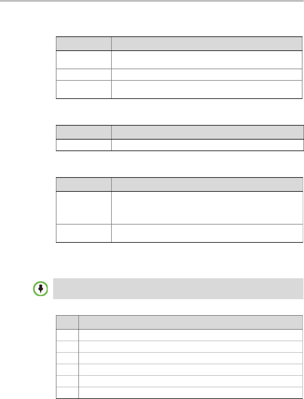
Appendix C-CDR Fields - Unformatted File
Polycom, Inc. C-33
Disconnection Cause Values
Table C-36 Event Fields for Event 111 - OPERATOR BACK TO CONFERENCE PARTY
Field Description
Operator Name The login name of the operator moving the participant back to the
conference.
Party Name The name of the participant being moved.
Party ID The identification number, as assigned by the MCU, of the participant being
moved.
Table C-37 Event Fields for Events 2011, 2012, and 2016
Field Description
IP V6 IPv6 address of the participant’s endpoint.
Table C-38 Event Fields for Event 3010 - PARTICIPANT INFORMATION
Field Description
Info1
Info2
Info3
Info4
The participant information fields.
These fields enable users to enter general information about the participant,
such as the participant’s e-mail address.
The maximum length of each field is 80 characters.
VIP Not supported.
Always contains the value 0.
For an explanation of the disconnection causes, see Appendix A: "Disconnection Causes” on
page A-1.
Table C-39 Disconnection Cause Values
Value Call Disconnection Cause
0 Unknown
1 Participant hung up
2 Disconnected by User
5 Resources deficiency
6 Password failure
20 H323 call close. No port left for audio

RealPresence Collaboration Server Virtual Edition Administrator’s Guide
C-34 Polycom, Inc.
21 H323 call close. No port left for video
22 H323 call close. No port left for FECC
23 H323 call close. No control port left
25 H323 call close. No port left for video content
51 A common key exchange algorithm could not be established between the MCU and the
remote device
53 Remote device did not open the encryption signaling channel
59 The remote devices’ selected encryption algorithm does not match the local selected
encryption algorithm
141 Called party not registered
145 Caller not registered
152 H323 call close. ARQ timeout
153 H323 call close. DRQ timeout
154 H323 call close. Alt Gatekeeper failure
191 H323 call close. Remote busy
192 H323 call close. Normal
193 H323 call close. Remote reject
194 H323 call close. Remote unreachable
195 H323 call close. Unknown reason
198 H323 call close. Small bandwidth
199 H323 call close. Gatekeeper failure
200 H323 call close. Gatekeeper reject ARQ
201 H323 call close. No port left
202 H323 call close. Gatekeeper DRQ
203 H323 call close. No destination IP value
204 H323 call close. Remote has not sent capability
205 H323 call close. Audio channels not open
207 H323 call close. Bad remote cap
208 H323 call close. Capabilities not accepted by remote
209 H323 failure
210 H323 call close. Remote stop responding
Table C-39 Disconnection Cause Values (Continued)
Value Call Disconnection Cause

Appendix C-CDR Fields - Unformatted File
Polycom, Inc. C-35
213 H323 call close. Master slave problem
251 SIP timer popped out
252 SIP card rejected channels
253 SIP capabilities don’t match
254 SIP remote closed call
255 SIP remote cancelled call
256 SIP bad status
257 SIP remote stopped responding
258 SIP remote unreachable
259 SIP transport error
260 SIP bad name
261 SIP trans error TCP invite
300 SIP redirection 300
301 SIP moved permanently
302 SIP moved temporarily
305 SIP redirection 305
380 SIP redirection 380
400 SIP client error 400
401 SIP unauthorized
402 SIP client error 402
403 SIP forbidden
404 SIP not found
405 SIP client error 405
406 SIP client error 406
407 SIP client error 407
408 SIP request timeout
409 SIP client error 409
410 SIP gone
411 SIP client error 411
413 SIP client error 413
414 SIP client error 414
Table C-39 Disconnection Cause Values (Continued)
Value Call Disconnection Cause

RealPresence Collaboration Server Virtual Edition Administrator’s Guide
C-36 Polycom, Inc.
MGC Manager Events that are not Supported by the
Collaboration Server
The following MGC Manager events are not supported by the Collaboration Server:
• Event 8 - REMOTE COM MODE
• Event 11 - ATM CHANNEL CONNECTED
• Event 12 - ATM CHANNEL DISCONNECTED
415 SIP unsupported media type
420 SIP client error 420
480 SIP temporarily not available
481 SIP client error 481
482 SIP client error 482
483 SIP client error 483
484 SIP client error 484
485 SIP client error 485
486 SIP busy here
487 SIP request terminated
488 SIP client error 488
500 SIP server error 500
501 SIP server error 501
502 SIP server error 502
503 SIP server error 503
504 SIP server error 504
505 SIP server error 505
600 SIP busy everywhere
603 SIP global failure 603
604 SIP global failure 604
606 SIP global failure 606
Table C-39 Disconnection Cause Values (Continued)
Value Call Disconnection Cause
For details of these events see the MGC Manager User’s Guide Volume II, Appendix A.

Appendix C-CDR Fields - Unformatted File
Polycom, Inc. C-37
• Event 13 - MPI CHANNEL CONNECTED
• Event 14 - MPI CHANNEL DISCONNECTED
• Event 15 - H323 CALL SETUP
• Event 16 - H323 CLEAR INDICATION
• Event 24 - SIP CALL SETUP
• Event 25 - SIP CLEAR INDICATION
• Event 27 - RECORDING SYSTEM LINK
• Event 110 - OPERATOR ON HOLD PARTY
• Event 113 - CONFERENCE REMARKS
• Event 2108 - OPERATOR MOVE PARTY TO CONFERENCE CONTINUE 1
• Event 3001 - CONFERENCE START CONTINUE 2
• Event 3108 - OPERATOR MOVE PARTY TO CONFERENCE CONTINUE 2
• Event 4001 - CONFERENCE START CONTINUE 3
• Event 4108 - OPERATOR MOVE PARTY TO CONFERENCE CONTINUE 3

RealPresence Collaboration Server Virtual Edition Administrator’s Guide
C-38 Polycom, Inc.

Polycom, Inc. D-1
Appendix D
Ad Hoc Conferencing and External
Database Authentication
The RealPresence Collaboration Server Virtual Edition Ad Hoc conferencing feature enables
participants to start ongoing conferences on-the-fly, without prior definition when dialing an
Ad Hoc-enabled Entry Queue. The created conference parameters are taken from the Profile
assigned to the Ad Hoc-enabled Entry Queue.
Ad Hoc conferencing is available in two the following modes:
• Ad Hoc Conferencing without Authentication
Any participant can dial into an Entry Queue and initiate a new conference if the
conference does not exist. This mode is usually used for the organization’s internal Ad
Hoc conferencing.
•Ad Hoc Conferencing with External Database Authentication
In this mode, the participant’s right to start a new conference is validated against a
database.
The external database application can also be used to validate the participant’s right to join
an ongoing conference. Conference access authentication can be:
• Part of the Ad Hoc conferencing flow where the participants must be authorized before
they can enter the conference created in the Ad Hoc flow.
• Independent of Ad Hoc conferencing where conference access is validated for all
conferences running on the MCU regardless of the method in which the conference was
started.
Ad Hoc Conferencing without Authentication
A participant dials in to an Ad Hoc-enabled Entry Queue and starts a new conference based
on the Profile assigned to the Entry Queue. In this configuration, any participant connecting
to the Entry Queue can start a new conference, and no security mechanism is applied. This
mode is usually used in organizations where Ad Hoc conferences are started from within the
network and without security breach.
A conference is started using one of the following method:
1The participant dials in to the Ad Hoc-enabled Entry Queue.
2The Conference ID is requested by the system.
3The participant inputs a Conference ID via his/her endpoint remote control using
DTMF codes.
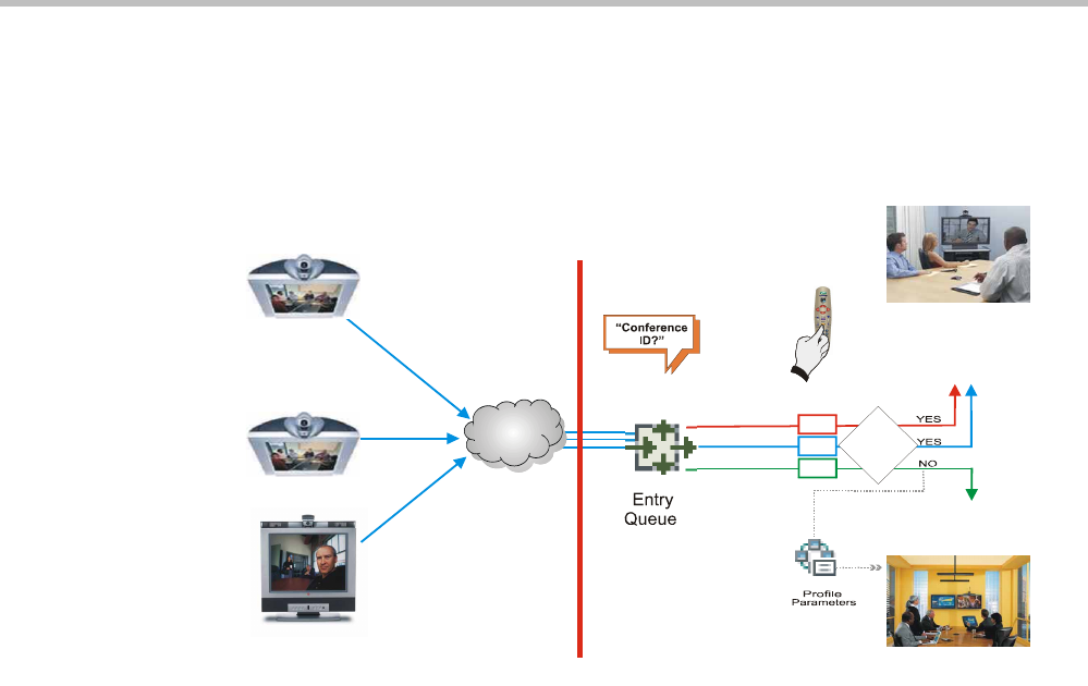
RealPresence Collaboration Server Virtual Edition Administrator’s Guide
D-2 Polycom, Inc.
4The MCU checks whether a conference with the same Conference ID is running on the
MCU. If there is such a conference, the participant is moved to that conference. If there
is no ongoing conference with that Conference ID, the system creates a new conference,
based on the Profile assigned to the Entry Queue, and connects this participant as the
conference chairperson.
Figure D-1 Ad Hoc Conference Initiation without Authentication
To enable this workflow, the following components must be defined in the system:
• An Entry Queue IVR Service with the appropriate audio file requesting the Conference
ID
• An Ad Hoc-enabled Entry Queue with an assigned Profile
Ad Hoc Conferencing with Authentication
The MCU can work with an external database application to validate the participant’s right
to start a new conference. The external database contains a list of participants, with their
assigned parameters. The conference ID entered by the participant is compared against the
database. If the system finds a match, the participant is granted the permission to start a new
conference.
To work with an external database application to validate the participant’s right to start a
new conference, the Entry Queue IVR Service must be configured to use the external
database application for authentication. In the external database application, you must
define all participants (users) with rights to start a new conference using Ad Hoc
conferencing. For each user defined in the database, you enter the conference ID,
Conference Password (optional) and Chairperson Password (when applicable), billing code,
Conference general information (corresponding to the User Defined 1 field in the Profile
properties) and user’s PIN code. The same user definitions can be used for conference access
authentication, that is, to determine who can join the conference as a participant and who as
a chairperson.
1
0
0
1
1
0
0
1
1
3
0
0
On Going
Conference
with this ID?
Maple_Room
Conference ID: 1001
New Conference
ID: 1300
Network
Numeric ID: 1000
Name: DefaultEQ
9251000
9251000
MCU
IP Endpoint
IP Endpoint
MCU
Gatekeeper - 925
Prefix in
925DefaultEQ
IP Endpoint
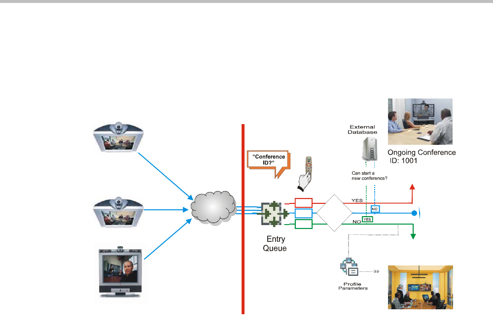
Appendix D-Ad Hoc Conferencing and External Database Authentication
Polycom, Inc. D-3
Entry Queue Level - Conference Initiation Validation with an External
Database Application
Starting a new conference with external database application validation entails the
following steps:
Figure D-2 Conference Initiation Validation with External Database Application
1The participant dials in to an Ad Hoc-enabled Entry Queue.
2The participant is requested to enter the Conference ID.
3The participant enters the conference ID via his/her endpoint remote control using
DTMF codes. If there is an ongoing conference with this Conference ID, the participant
is moved to that conference where another authentication process can occur, depending
on the IVR Service configuration.
4If there is no ongoing conference with that Conference ID, the MCU verifies the
Conference ID with the database application that compares it against its database. If the
database application finds a match, the external database application sends a response
back to the MCU, granting the participant the right to start a new ongoing conference.
If this Conference ID is not registered in the database, the conference cannot be started
and this participant is disconnected from the Entry Queue.
5The external database contains a list of participants (users), with their assigned
parameters. Once a participant is identified in the database (according to the conference
ID), his/her parameters (as defined in the database) can be sent to the MCU in the same
response granting the participant the right to start a new ongoing conference. These
parameters are:
—Conference Name
—Conference Billing code
—Conference Password
—Chairperson Password
1200
1001
1300
On Going
Conference
with this ID?
Network
Numeric ID: 1000
Name: DefaultEQ
9251000
9251000
MCU
IP Endpoint
IP Endpoint
MCU
Gatekeeper - 925
Prefix in
925DefaultEQ
IP Endpoint
New Conference
ID: 1300

RealPresence Collaboration Server Virtual Edition Administrator’s Guide
D-4 Polycom, Inc.
—Conference Information, such as the contact person name. These fields correspond
to Info 1, 2 and 3 fields in the Conference Properties - Information dialog box.
—Maximum number of participants allowed for the conference
—Conference Owner
These parameters can also be defined in the conference Profile. In such a case,
parameters sent from the database overwrite the parameters defined in the Profile. If
these parameters are not sent from the external database to the MCU, they will be taken
from the Profile.
6A new conference is started based on the Profile assigned to the Entry Queue.
7The participant is moved to the conference.
If no password request is configured in the Conference IVR Service assigned to the
conference, the participant that initiated the conference is directly connected to the
conference, as its chairperson.
If the Conference IVR Service assigned to the conference is configured to prompt for the
conference password and chairperson password, without external database
authentication, the participant has to enter these passwords in order to join the
conference.
To enable this workflow, the following components must be defined in the system:
• A Conference IVR Service with the appropriate prompts. If conference access is also
validated with the external database application it must be configured to access the
external database for authentication.
• An Entry Queue IVR Service configured with the appropriate audio prompts
requesting the Conference ID and configured to access the external database for
authentication.
• Create a Profile with the appropriate conference parameters and the appropriate
Conference IVR Service assigned to it.
• An Ad Hoc-enabled Entry Queue with the appropriate Entry Queue IVR Service and
Conference Profile assigned to it.
• An external database application with a database containing Conference IDs associated
with participants and their relevant properties.
• Define the flags required to access the external database in System Configuration.
For more information, see Figure , “MCU Configuration to Communicate with an External
Database Application” on page D-9.
Conference Access with External Database
Authentication
The MCU can work with an external database application to validate the participant’s right
to join an existing conference. The external database contains a list of participants, with their
assigned parameters. The conference password or chairperson password entered by the
participant is compared against the database. If the system finds a match, the participant is
granted the permission to access the conference.
To work with an external database application to validate the participant’s right to join the
conference, the Conference IVR Service must be configured to use the external database
application for authentication.
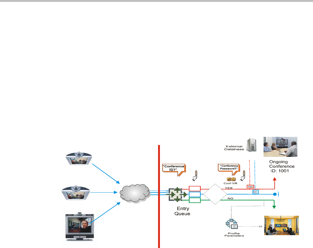
Appendix D-Ad Hoc Conferencing and External Database Authentication
Polycom, Inc. D-5
Conference access authentication can be performed as:
• Part of the Ad Hoc conferencing flow where the participants must be authorized before
they can enter the conference created in the Ad Hoc flow
• Independent of Ad Hoc conferencing where conference access is validated for all
conferences running on the MCU regardless of the method in which the conference was
started.
Conference access authentication can be implemented for all participants joining the
conference or for chairpersons only.
Conference Access Validation - All Participants (Always)
Once the conference is created either via an Ad Hoc Entry Queue, or a standard ongoing
conference, the right to join the conference is authenticated with the external database
application for all participants connecting to the conference.
Figure D-3 Conference Access - Conference Password validation with External Database Application
Joining the conference entails the following steps:
• When the conference is started (either in the Ad Hoc flow or in the standard method),
all participants connecting to the conference are moved to the Conference IVR queue
where they are prompted for the conference password.
• When the participant enters the conference password or his/her personal password, it
is sent to the external database application for validation.
• If there is a match, the participant is granted the right to join the conference. In addition,
the external database application sends to the MCU the following parameters:
—Participant name (display name)
—Whether or not the participant is the conference chairperson
—Participant Information, such as the participant E-mail. These fields correspond to
Info 1, 2, 3 and 4 fields in the Participant Properties - Information dialog box.
If there is no match (i.e. the conference or personal password are not defined in the
database), the request to access the conference is rejected and the participant is
disconnected from the MCU.
1001
1001
1300
On Going
Conference
with this ID?
Network
Numeric ID: 1000
Name: DefaultEQ
9251000
9251000
MCU
IP Endpoint
IP Endpoint
MCU
Gatekeeper - 925
Prefix in
925DefaultEQ
IP Endpoint
New Conference
ID: 1300
C o rre c t
Pa ss w o rd ?
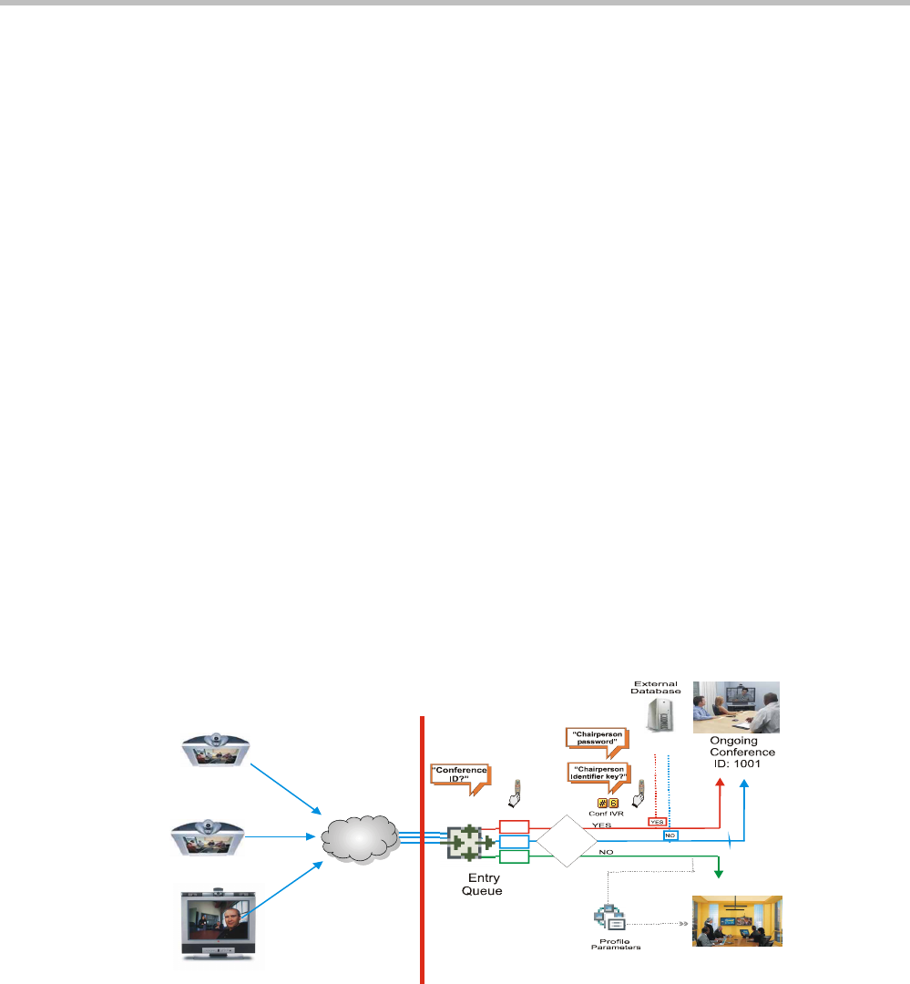
RealPresence Collaboration Server Virtual Edition Administrator’s Guide
D-6 Polycom, Inc.
• If the Conference IVR Service is configured to prompt for the chairperson identifier and
password, the participant is requested to enter the chairperson identifier.
—If no identifier is entered, the participant connects as a standard, undefined
participant.
• If the chairperson identifier is entered, the participant is requested to enter the
chairperson password. In this flow, the chairperson password is not validated with the
external database application, only with the MCU.
—If the correct chairperson password is entered, the participant is connected to the
conference as its chairperson.
—If the wrong password is entered, he/she is disconnected from the conference.
To enable conference access validation for all participants the following conferencing
components are required:
• The external database must hold the conference password or the participant personal
password/PIN code or the participant’s Alias.
• The Conference IVR Service assigned to the conference (defined in the Profile) must be
configured to authenticate the participant’s right to access the conference with the
external database application for all requests. In addition it must be configured to
prompt for the Conference Password.
Conference Access Validation - Chairperson Only (Upon Request)
An alternative validation method at the conference level is checking only the chairperson
password with the external database application. All other participants can be checked only
with the MCU (if the Conference IVR Service is configured to prompt for the conference
password) or not checked at all (if the Conference IVR Service is configured to prompt only
for the chairperson password).
Figure D-4 Conference Access - Chairperson Password validation with external database application
Joining the conference entails the following steps:
• When the conference is started (either in the Ad Hoc flow or in the standard method),
all participants connecting to the conference are moved to the conference IVR queue
where they are prompted for the conference password.
1001
1001
1300
On Going
Conference
with this ID?
Network
Numeric ID: 1000
Name: DefaultEQ
9251000
9251000
MCU
IP Endpoint
IP Endpoint
MCU
Gatekeeper - 925
Prefix in
925DefaultEQ
IP Endpoint
New Conference
ID: 1300
Chairperson
Pa ssw o r d ?
Enters the
conference as
Chairp erson
Enters the
conference as
st a nd a rd
p a rtic ip a nt

Appendix D-Ad Hoc Conferencing and External Database Authentication
Polycom, Inc. D-7
• If the Conference IVR Service is configured to prompt for the Conference password, the
participant is requested to enter the conference password. In this flow, the conference
password is not validated with the external database application, only with the MCU.
—If the wrong password is entered, he/she is disconnected from the conference.
• If the correct conference password is entered, the participant is prompted to enter the
chairperson identifier key.
—If no identifier is entered, the participant is connected to the conference as a
standard participant.
• If the chairperson identifier is entered, the participant is prompted to enter the
chairperson password.
• When the participant enters the chairperson password or his/her personal password, it
is sent to the external database application for validation.
—If the password is incorrect the participant is disconnected from the MCU.
• If there is a match, the participant is granted the right to join the conference as
chairperson. In addition, the external database application sends to the MCU the
following parameters:
—Participant name (display name)
—Participant Information, such as the participant E-mail. These fields correspond to
Info 1, 2, 3 and 4 fields in the Participant Properties - Information dialog box.
To enable conference access validation for all participants the following conferencing
components are required:
• The external database must hold the Chairperson Password or the participant’s Alias.
• The Conference IVR Service assigned to the conference (defined in the Profile) must be
configured to check the external database for the Chairperson password only when the
participant enters the chairperson identifier key (either pound or star). In addition, it
must be configured to prompt for the chairperson identifier key and password.
System Settings for Ad Hoc Conferencing and External
Database Authentication
Ad Hoc Settings
Before a participant can initiate an Ad Hoc conference (with or without authentication), the
following components must be defined:
•Profiles
Defines the conference parameters for the conferences that will be initiated from the Ad
Hoc-enabled Entry Queue. For more details, see "Conference Profiles” on page 2-1.
•Entry Queue IVR Service with Conference ID Request Enabled
The Entry Queue Service is used to route participants to their destination conferences,
or create a new conference with this ID. For details, see "IVR Services” on page 16-1.
In Ad Hoc conferencing, the Conference ID is used to check whether the destination
conference is already running on the MCU and if not, to start a new conference using
this ID.

RealPresence Collaboration Server Virtual Edition Administrator’s Guide
D-8 Polycom, Inc.
•Ad Hoc - enabled Entry Queue
Ad Hoc conferencing must be enabled in the Entry Queue and a Profile must be
assigned to the Entry Queue. In addition, an Entry Queue IVR Service supporting
conference ID request. For details, see "Entry Queues” on page 7-1..
Authentication Settings
•MCU Configuration
Usage of an external database application for authentication (for starting new
conferences or joining ongoing conferences) is configured for the MCU in the System
Configuration. For details, see "MCU Configuration to Communicate with an External
Database Application” on page D-9.
•Entry Queue IVR Service with Conference Initiation Authentication Enabled
Set the Entry Queue IVR Service to send authentication requests to the external
database application to verify the participant’s right to start a new conference according
to the Conference ID entered by the participant. For details, see "Enabling External
Database Validation for Starting New Ongoing Conferences” on page D-10.
•Conference IVR Service with Conference Access Authentication Enabled
Set the Conference IVR Service to send authentication requests to the external database
application to verify the participant’s right to connect to the conference as a standard
participant or as a chairperson. For details, see "Enabling External Database Validation for
Conferences Access” on page D-10.
•External Database Application Settings
The external database contains a list of participants (users), with their assigned
parameters. These parameters are:
—Conference Name
—Conference Billing code
—Conference Password
—Chairperson Password
—Conference Information, such as the contact person name. These fields correspond
to Info 1, 2 and 3 fields in the Conference Properties - Information dialog box.
—Maximum number of participants allowed for the conference
—Conference Owner
—Participant name (display name)
—Participant Information, such as the participant E-mail. These fields correspond to
Info 1, 2, 3 and 4 fields in the Participant Properties - Information dialog box.
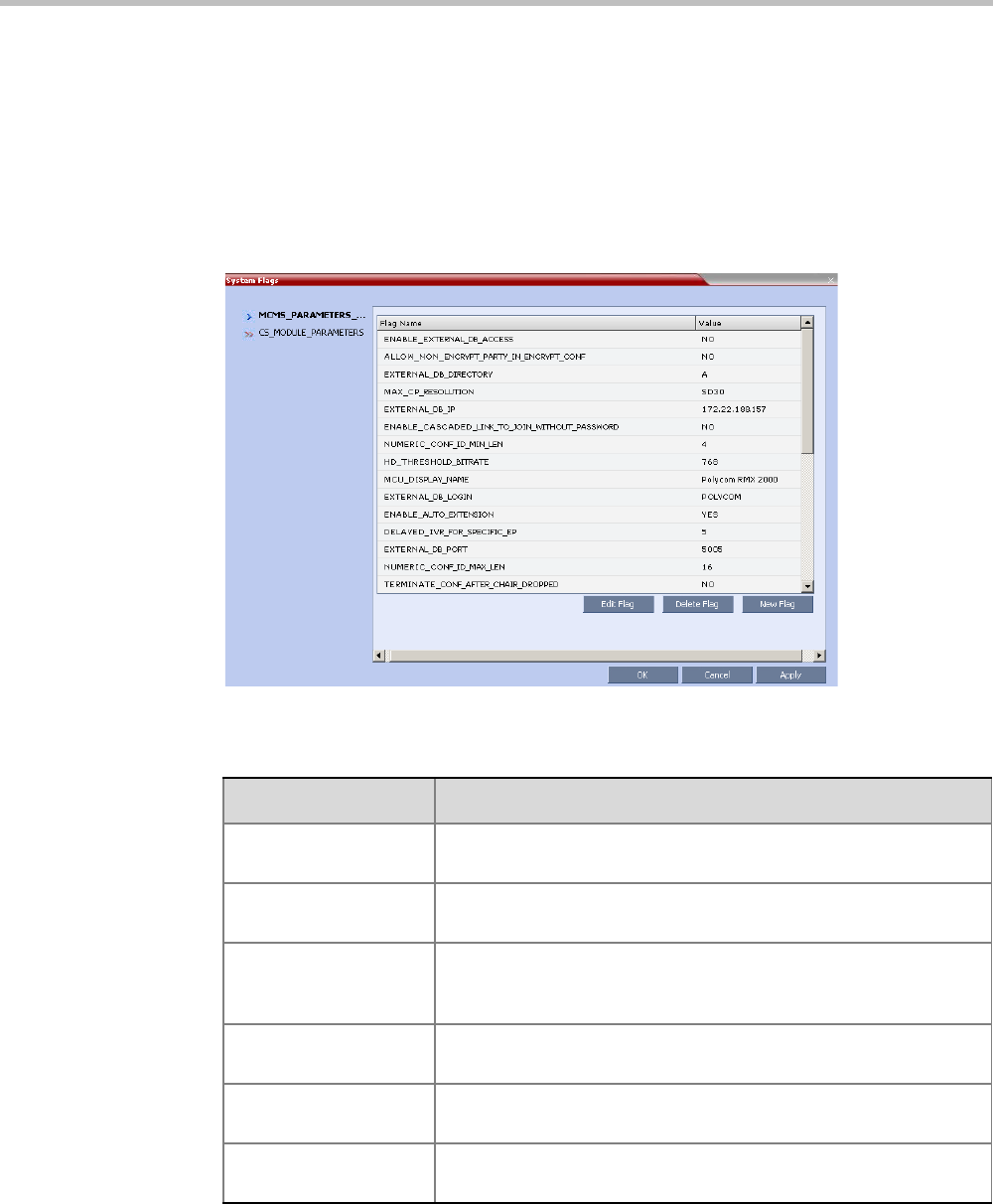
Appendix D-Ad Hoc Conferencing and External Database Authentication
Polycom, Inc. D-9
MCU Configuration to Communicate with an External Database
Application
To enable the communication with the external database application, several flags must be
set in the System Configuration.
To set the System Configuration flags:
1On the Setup menu, click System Configuration.
The System Flags dialog box opens.
2Modify the values of the following flags:
3Click OK.
4Reset the MCU for flag changes to take effect.
Table D-1 Flag Values for Accessing External Database Application
Flag Description and Value
ENABLE_EXTERNAL_
DB_ACCESS
The flag that enables the use of the external database application.
EXTERNAL_DB_IP The IP address of the external database application server. default
IP: 0.0.0.0.
EXTERNAL_DB_POR
T
The port number used by the MCU to access the external
application server.
Default Port = 80.
EXTERNAL_DB_LOGI
N
The user name defined in the external database application for the
MCU.
EXTERNAL_DB_PASS
WORD
The password associated with the user name defined for the MCU
in the external database application.
EXTERNAL_DB_DIRE
CTORY
The URL of the external database application.
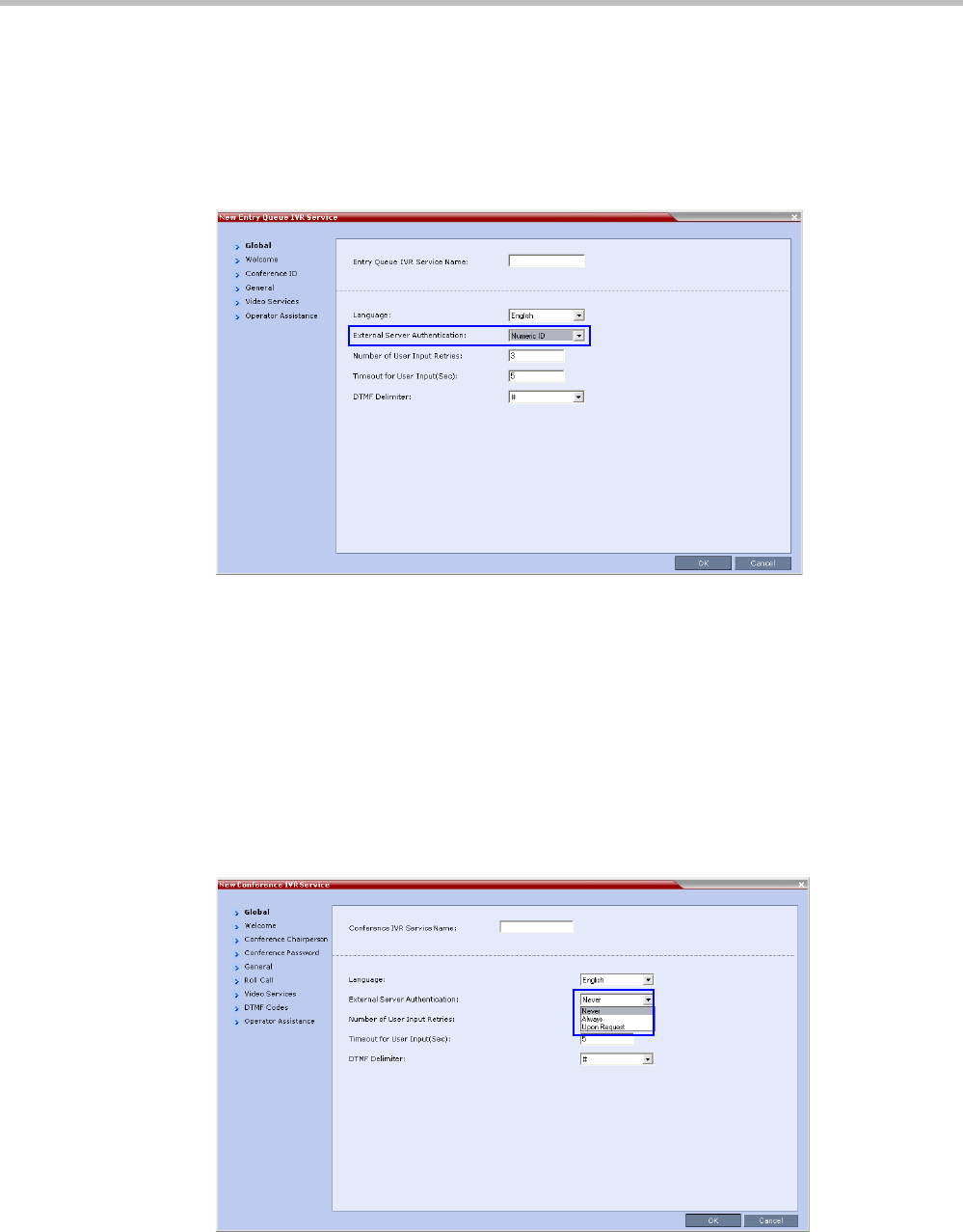
RealPresence Collaboration Server Virtual Edition Administrator’s Guide
D-10 Polycom, Inc.
Enabling External Database Validation for Starting New Ongoing
Conferences
The validation of the participant’s right to start a new conference with an external database
application is configured in the Entry Queue IVR Service - Global dialog box.
>> Set the External Server Authentication field to Numeric ID.
Enabling External Database Validation for Conferences Access
The validation of the participant’s right to join an ongoing conference with an external
database application is configured in the Conference IVR Service - Global dialog box.
You can set the system to validate all the participants joining the conference or just the
chairperson.
>> Set the External Server Authentication field to:
— Always - to validate the participant’s right to join an ongoing conference for all
participants
—Upon Request - to validate the participant’s right to join an ongoing conference as
chairperson
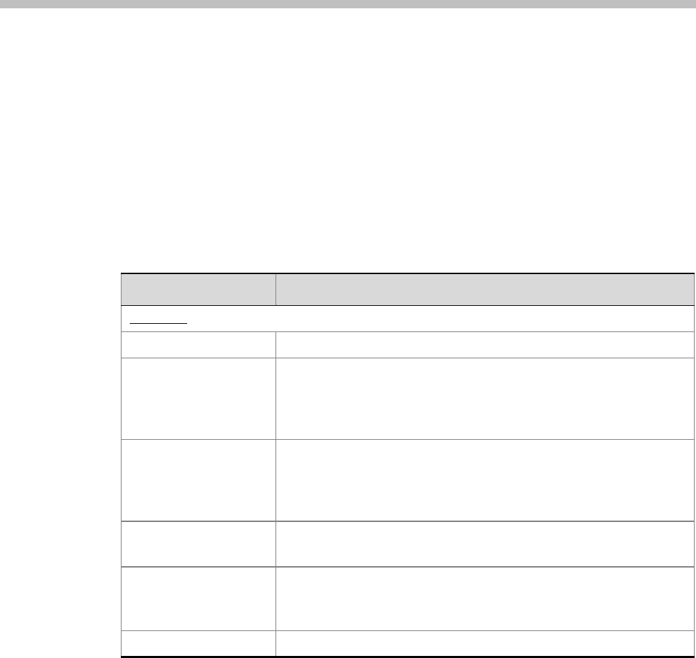
Polycom, Inc. E-1
Appendix E
Participant Properties Advanced
Channel Information
The following appendix details the properties connected with information about audio and
video parameters, as well as, problems with the network which can affect the audio and
video quality.
Table E-1 Participant Properties - Channel Status Advanced Parameters
Field Description
Media Info
Algorithm Indicates the audio or video algorithm and protocol.
Frame per packet (audio
only)
The number of audio frames per packet that are transferred between the
MCU and the endpoint. If the actual Frame per Packets are higher than
Frame per Packets declared during the capabilities exchange, a Faulty
flag is displayed.
Resolution
(video only)
Indicates the video resolution in use. If the actual resolution is higher than
resolution declared in the capabilities exchange, the Faulty flag is dis-
played. For example, if the declared resolution is CIF and the actual reso-
lution is 4CIF, the Faulty flag is displayed.
Frame Rate
(video only)
The number of video frames per second that are transferred between the
MCU and the endpoint.
Annexes (video only) Indicates the H.263 annexes in use at the time of the last RTCP report. If
the actual annexes used are other than the declared annexes in the capa-
bilities exchange, the Faulty flag is displayed.
Channel Index For Polycom Internal use only.

RealPresence Collaboration Server Virtual Edition Administrator’s Guide
E-2 Polycom, Inc.
RTP Statistics
Actual loss The number of missing packets counted by the IP card as reported in the
last RTP Statistics report. If a packet that was considered lost arrives
later, it is deducted from the packet loss count. Packet loss is displayed
with the following details:
•Accumulated N - number of lost packets accumulated since the
channel opened.
•Accumulated % - percentage of lost packets out of the total number
of packets transmitted since the channel opened.
•Interval N - number of packets lost in the last RTP report interval
(default interval is 5 minutes).
•Interval % - percentage of lost packets out of the total number of
packets transmitted in the last RTP report interval (default interval is 5
minutes).
•Peak - the highest number of lost packets in a report interval from the
beginning of the channel's life span.
Out of Order The number of packets arriving out of order. The
following details are displayed:
•Accumulated N - total number of packets that arrived out of order
since the channel opened.
•Accumulated % - percentage of packets that arrived out of order out
of the total number of packets transmitted since the channel opened.
•Interval N - number of packets that arrived out of order in the last RTP
report interval (default interval is 5 minutes).
•Interval % - percentage of packets that arrived out of order out of the
total number of packets transmitted in the last RTP report interval
(default interval is 5 minutes).
•Peak - the highest number of packets that arrived out of order in a
report interval from the beginning of the channel's life span.
Table E-1 Participant Properties - Channel Status Advanced Parameters (Continued)
Field Description
Appendix E-Participant Properties Advanced Channel Information
Polycom, Inc. E-3
Fragmented Indicates the number of packets that arrived to the IP card fragmented
(i.e., a single packet broken by the network into multiple packets). This
value can indicate the delay and reordering of fragmented packets that
require additional processing, but is not considered a fault.
The Fragmented information is displayed with the following details:
•Accumulated N - total number of packets that were fragmented since
the channel opened.
•Accumulated % - percentage of fragmented packets out of the total
number of packets transmitted since the channel opened.
•Interval N - number of fragmented packets received in the last RTP
report interval (default interval is 5 minutes).
•Interval % - percentage of fragmented packets out of the total number
of packets transmitted in the last RTP report interval (default interval is
5 minutes).
•Peak - the highest number of fragmented packets in a report interval
from the beginning of the channel's life span.
Table E-1 Participant Properties - Channel Status Advanced Parameters (Continued)
Field Description

RealPresence Collaboration Server Virtual Edition Administrator’s Guide
E-4 Polycom, Inc.

Polycom, Inc. F-1
Appendix F
Secure Communication Mode
The RealPresence Collaboration Server can be configured to work in Secure Mode by configuring
the Collaboration Server and the Collaboration Server Web Client to work with SSL/TLS.
In this mode, a SSL/TLS Certificate is installed on the MCU, setting the MCU Listening Port
to secured port 4433.
TLS is a cryptographic protocol used to ensure secure communications on public networks.
TLS uses a Certificate purchased from a trusted third party Certificate Authority to authenticate
public keys that are used in conjunction with private keys to ensure secure communications
across the network.
The Collaboration Server supports:
• TLS 1.0
• SSL 3.0 (Secure Socket Layer)
SSL 3.0 utilizes 1024-bit RSA public key encryption.
TLS certificates can be generated using the following methods: CSR, PFX and PEM; each
giving different options for Encryption Key length. Table F-1 lists the SIP TLS Encryption Key
length support for the various system components.
Certificate Configuration and Management
All Polycom devices used in a Maximum Security Environment require security certificates.
Certificate Template Requirements
The specific security certificate requirements for Collaboration Servers used in Maximum
Security Environments are:
• Support of 2048-bit encryption keys.
Table F-1 SIP TLS - Encryption Key Support by System Component
System Component Key Generation Method Key Length (bits) Key generated by
SIP Signaling
CSR 2048 Collaboration
Server
PFX / PEM 1024 or 2048 User
Management
CSR 2048 Collaboration
Server
LDAP

Polycom® RealPresence Collaboration ServerVirtual Edition Administrator’s Guide
F-2 Polycom, Inc.
•Support of Extended Key Usage (EKU) for both:
—Client Authentication
—Server Authentication
The certificate template used by your CA server may need modification to meet the
Collaboration Server requirements.
Certificate Requirements for Polycom Devices
Each Polycom device must have security certificates for the entire Chain Of Trust.
The Collaboration Server must have:
• The public certificate of each server in the CA Chain or hierarchy that issued its
certificate.
For example: RootCA IntermediateCA SubCA
The public certificates of the chain that issued the administrator’s identity certificate. For
example: UserRootCA UserIntermediateCA UserSubCA
Configure Certificate Management
Within a PKI environment, certificate revocation policies are used to ensure that certificates
are valid. Certificates can expire or be revoked for various reasons (RFC 5280).
The Collaboration Server enforces these certificate revocation policies through Certificate
Revocation Lists (CRLs). CRLs are required for each CA Chain in use by the Collaboration
Server. These CRL files must be kept current
Switching to Secure Mode
The following operations are required to switch the Collaboration Server to Secure Mode:
• Purchase and Install the SSL/TLS certificate
• Modify the Management Network settings
• Create/Modify the relevant System Flags
Purchasing a Certificate
Once a certificate is purchased and received it is stored in the Collaboration Server and used
for all subsequent secured connections.
To create/purchase a certificate:
1In the Collaboration Server menu, click Setup > RMX Secured Communication >
Create certificate request.
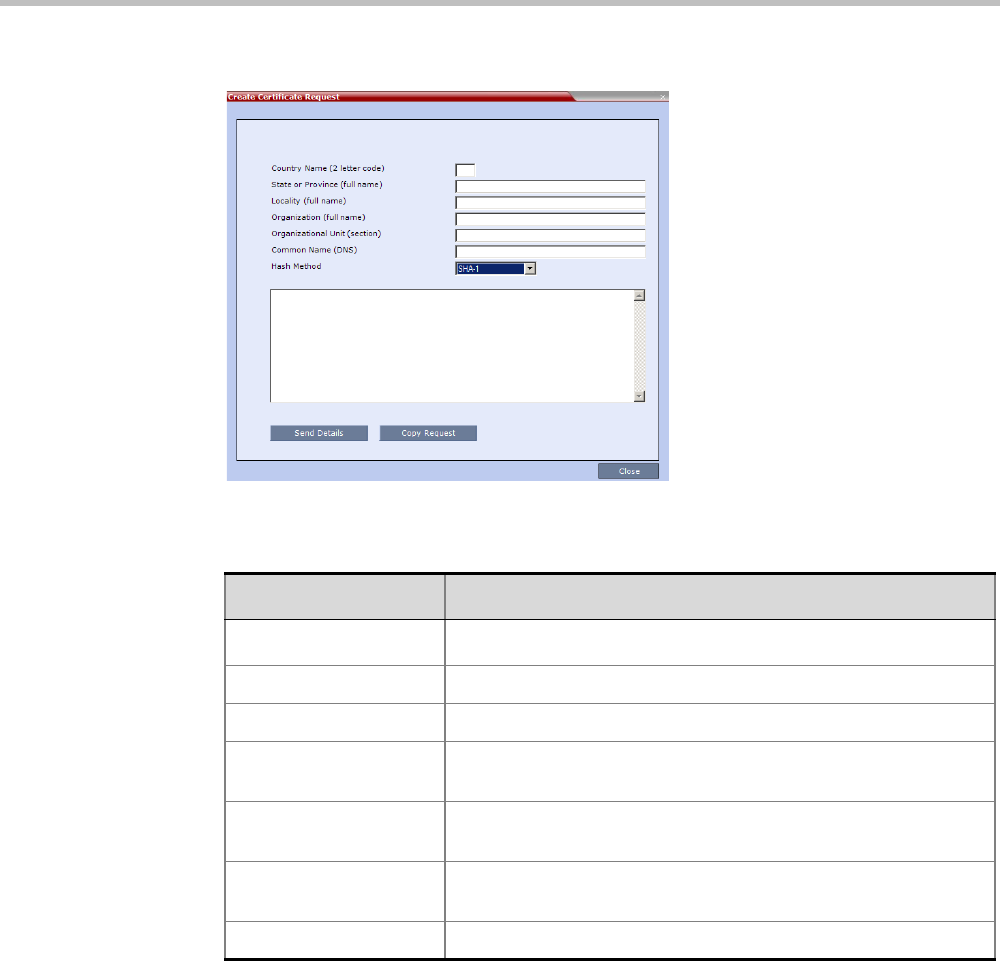
Appendix F-Secure Communication Mode
Polycom, Inc. F-3
The Create Certificate Request dialog box is displayed.
2Enter information in all the following fields:
3Click Send Details.
Table F-2 Create Certificate Request
Field Description
Country Name Enter any 2 letter code for the country name.
State or Province Enter the full name of the state or province.
Locality Enter the full name of the town/city/location.
Organization Enter the full name of your organization for which the certificate
will be issued.
Organizational Unit Enter the full name of the unit (group or division) for which the
certificate will be issued.
Common Name (DNS/
IP)
Enter the DNS MCU Host Name. This MCU Host Name must also
be configured in the Management Network Properties dialog box.
Hash Method Select the Hash method for the certificate.
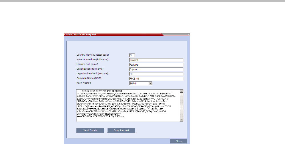
Polycom® RealPresence Collaboration ServerVirtual Edition Administrator’s Guide
F-4 Polycom, Inc.
The Collaboration Server creates a New Certificate Request and returns it to the Create
Certificate Request dialog box along with the information the user submitted.
4Click Copy Request to copy the New Certificate Request to the workstation’s clipboard.
5Connect to your preferred Certificate Authority’s website using the web browser.
6Follow the purchasing instructions at the Certificate Authority’s website.
Paste (Ctrl + V) the New Certificate Request as required by the Certificate Authority.
The Certificate Authority issues the TLS/SSL certificate, and sends the certificate to you
by e-mail.
Installing the Certificate
To install the certificate:
After you have received the certificate from the Certificate Authority:
1Copy (Ctrl + C) the certificate information from the Certificate Authority’s e-mail to the
clipboard.
2In the Collaboration Server menu, click Setup > RMX Secured Communication > Send
Certificate.
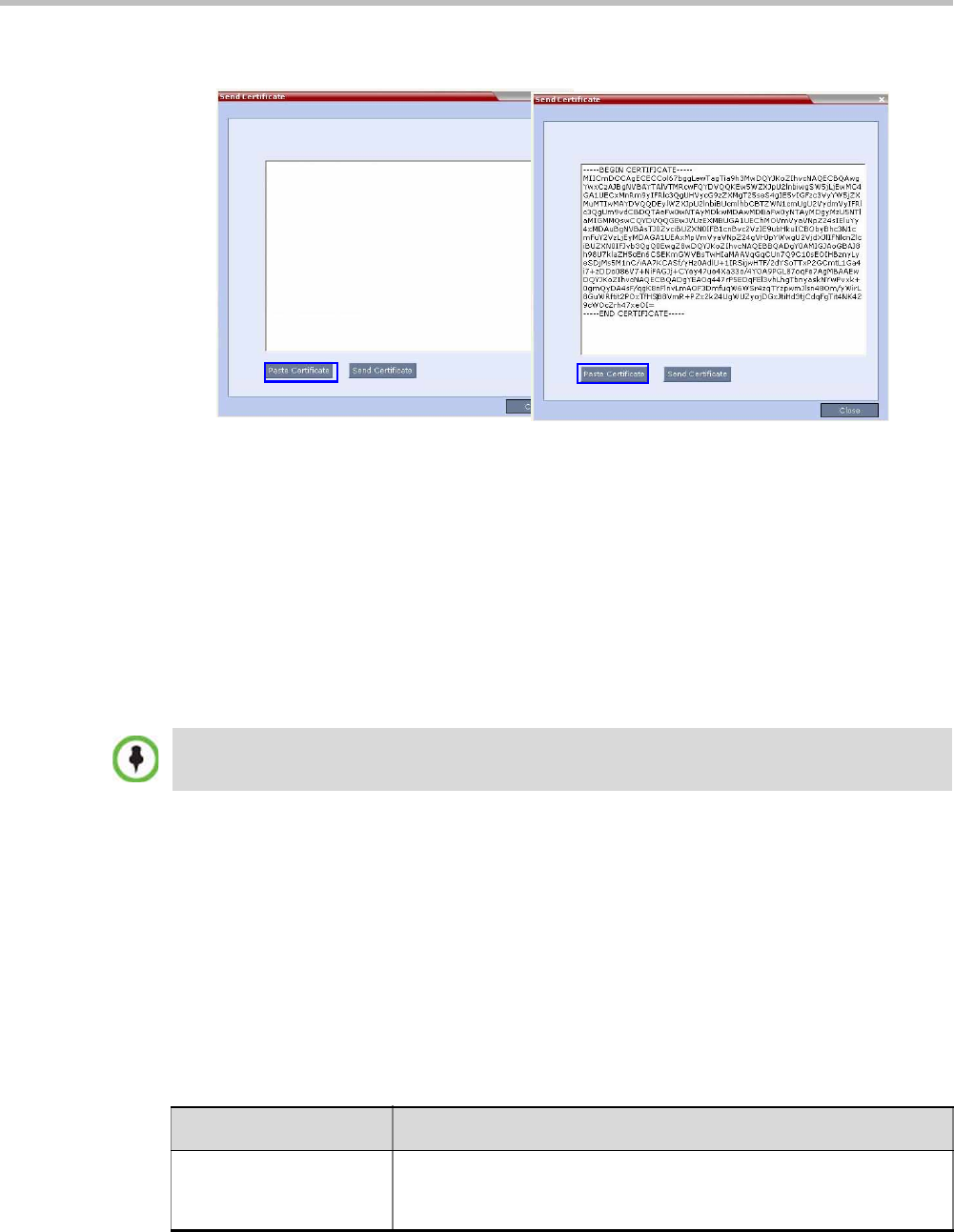
Appendix F-Secure Communication Mode
Polycom, Inc. F-5
3Click Paste Certificate to paste the clipboard content into the Send Certificate dialog box.
4Click the Send Certificate button to send the certificate to the Collaboration Server.
The MCU validates the certificate.
—If the certificate is not valid,an error message is displayed.
—If the certificate matches the private key, and the task is completed, a confirmation
message indicating that the certificate was created successfully is displayed.
A System Restart is not required at this point.
The certificate expiry date is checked daily. An active alarm is raised two weeks before
the certificate is due to expire, stating the number of days to expiry.
If the certificate expires, the Collaboration Server continues to work in secure mode and
an Active Alarm is raised with Security mode failed – Certificate expired in the description
field.
Creating/Modifying System Flags
The following System Flags in system.cfg control secure communications.
•RMX_MANAGEMENT_SECURITY_PROTOCOL
•EXTERNAL_DB_PORT
Table F-3, below, lists both flags and their settings.
If the System Flag, RMX_MANAGEMENT_SECURITY_PROTOCOL does not exist in the system, it
must be created by using the Setup menu.
For more information see "Modifying System Flags” on page 20-1.
Certificates are deleted when an administrator performs a Restore Factory Defaults with the
Comprehensive Restore option selected.
Table F-3 System Flags
Flag Description
RMX_MANAGEMENT_S
ECURITY_PROTOCOL
Enter the protocol to be used for secure communications.
Default: TLSV1_SSLV3 (both).
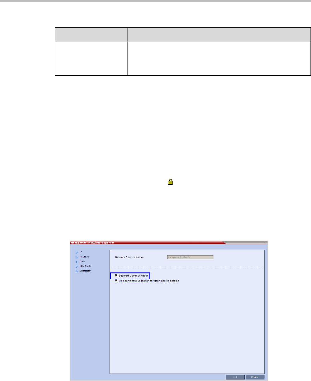
Polycom® RealPresence Collaboration ServerVirtual Edition Administrator’s Guide
F-6 Polycom, Inc.
The Collaboration Server must be restarted for modified flag settings to take effect.
Enabling Secure Communication Mode
After the SSL/TLS Certificate is installed, secure communications are enabled by modifying
the properties of the Management Network in the Management Network properties dialog box.
When Secure Communications Mode is enabled:
•Only https:// commands from the browser to the Control Unit IP Address of the
Collaboration Server are accepted.
• The Collaboration Server listens only on secured port 4433.
• All connection attempts on port 8080 are rejected.
• A secure communication indicator ( ) is displayed in the browser’s status bar.
To enable secure communications mode:
1In the Collaboration Server Management pane, click IP Network Services.
2In the IP Network Services list pane, double-click the Management Network entry.
3Click the Security tab.
The Management Security Properties dialog box is displayed.
4Select the Secured Communication check box.
5Click OK.
EXTERNAL_DB_PORT The external database server port used by the Collaboration Server to
send and receive XML requests/responses.
For secure communications set the value to 4433.
Default: 5005.
Table F-3 System Flags (Continued)
Flag Description
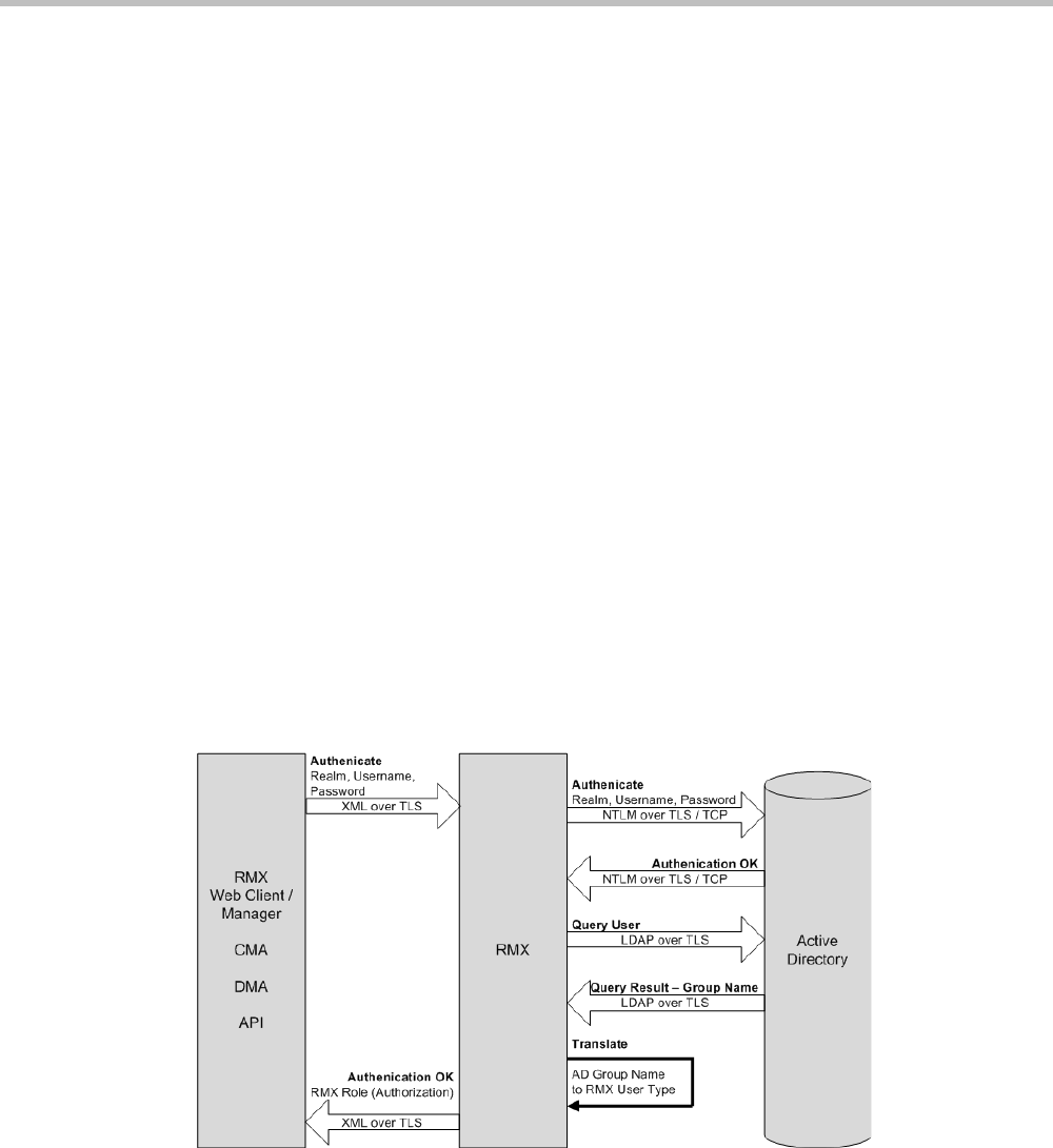
Appendix F-Secure Communication Mode
Polycom, Inc. F-7
Securing an External Database
TLS 1.0 is used when securing communications between the Collaboration Server and an
external database. The certificate is installed on the database server and the Collaboration
Server is the client. When the certificate is installed on the database server, all client requests
and responses are transferred via secure port 4433.
It is important to verify that the external database application is operating in secure mode
before enabling secure external database communications on the Collaboration Server. The
Collaboration Server checks the validity of external database’s certificate before
communicating. If there is a certificate error an Active Alarm is raised with Error in external
database certificate in the description field.
To enable secure Collaboration Server Communications with an External Database:
>> Set the Collaboration Server to communicate with the database server via port 4433 by
setting the value of the System Flag EXTERNAL_DB_PORT in system.cfg to 4433.
For more information see "Modifying System Flags” on page 20-1.
MS Active Directory Integration
It is possible to configure direct interaction between the Collaboration Server and Microsoft
Active Directory for Authentication and Authorization of Management Network users.
The following diagram shows a typical user authentication sequence between a User,
Collaboration Server and Active Directory.
Directory and Database Options
Standard Security Mode
Internal Collaboration Server database + External Database
First authentication is via the internal Collaboration Server database. If it is not successful,
authentication is via the External Database.

Polycom® RealPresence Collaboration ServerVirtual Edition Administrator’s Guide
F-8 Polycom, Inc.
Internal Collaboration Server database + External Database + Active Directory
•Management Logins
First authentication is via the internal Collaboration Server database. If it is not
successful, authentication is via the Active Directory.
•Conference Queries (Chairperson Password, Numerical ID etc.)
First authentication is via the internal Collaboration Server database. If it is not
successful, authentication is via the External Database.
Guidelines
• The Collaboration Server maintains a local record of:
—Audit Events – users that generate these events are marked as being either internal
or external.
—Successful user logins
—Failed user login attempts
• User passwords and user lockout policy for external users are managed via Active
Directory’s integration with the user’s host machine.
• Enabling or disabling Active Directory integration does not require a reset.
•In Standard Security Mode multiple accounts of all user types are supported.
•Multiple Machine Accounts with various roles are supported.
•Microsoft Active Directory is the only directory service supported.
•Active Directory integration is configured as part of the Management Network.
•In Standard Security Mode, the Active Directory can be queried using NTLM with or
without TLS encryption.
• Server and client certificate validation requests use LDAP with or without TLS
encryption.
When using LDAP over TLS, in addition to using port 389 with STARTTLS, the administrator has
the option of using port 636.
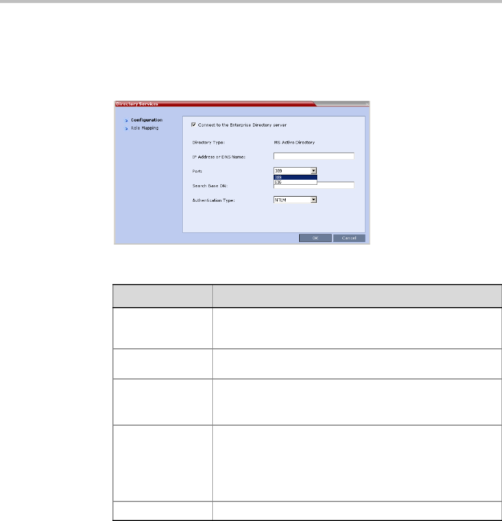
Appendix F-Secure Communication Mode
Polycom, Inc. F-9
Enabling Active Directory Integration
To configure Directory Services:
1On the Collaboration Server Menu, click Setup > Directory Services.
The Directory Services - Configuration dialog box is displayed.
2Modify the following fields.
Table F-4 Directory Services - Configuration
Field Description
Connect to the
Enterprise Directory
Server
Select this check box to enable or disable the Active Directory feature.
IP Address or DNS
Name
Enter the IP address or DNS name of the Enterprise Directory Server
(Active Directory).
Port Select the Port according to the Authentication Protocol to be used:
•389 - NTLM over TCP
•636 - NTLM over TLS
Search Base DN Enter the starting point when searching for User and Group
information in the Active Directory.
For example if the Domain Name is:
mainoffice.bigcorp.com.uk
The entry in this field should be:
CN=Users,DC=mainoffice,DC=bigcorp,DC=come,DC=uk
Authentication Type Only NTLM can be used.
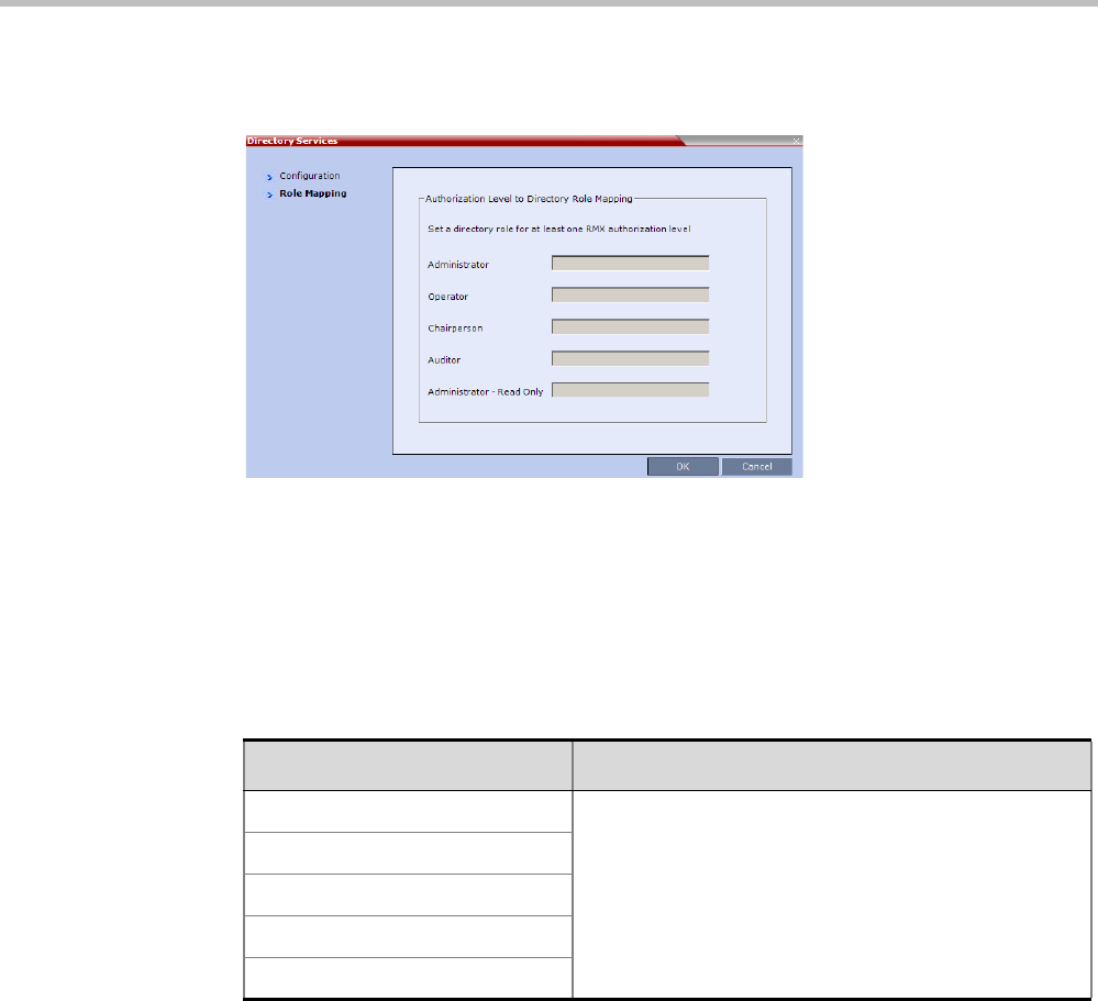
Polycom® RealPresence Collaboration ServerVirtual Edition Administrator’s Guide
F-10 Polycom, Inc.
3Click the Role Mapping tab.
The Directory Services - Role Mapping dialog box is displayed.
Each of the Collaboration Server user types: Administrator, Administrator Read-Only,
Auditor, Operator and Chairperson can be mapped to only one Active Directory Group or
Role according to the customer’s specific implementation.
—A Collaboration Server user that belongs to multiple Active Directory Groups is
assigned to the Group with the least privileges.
4Map the Collaboration Server User Types, to their Active Directory roles by modifying the
following fields.
5Click OK.
Table F-5 Directory Services - Role Mapping
Field Description
Administrator
At least one of these User Types must be mapped to an
Active Directory Role.
Administrator Read-Only
Operator
Chairperson
Auditor
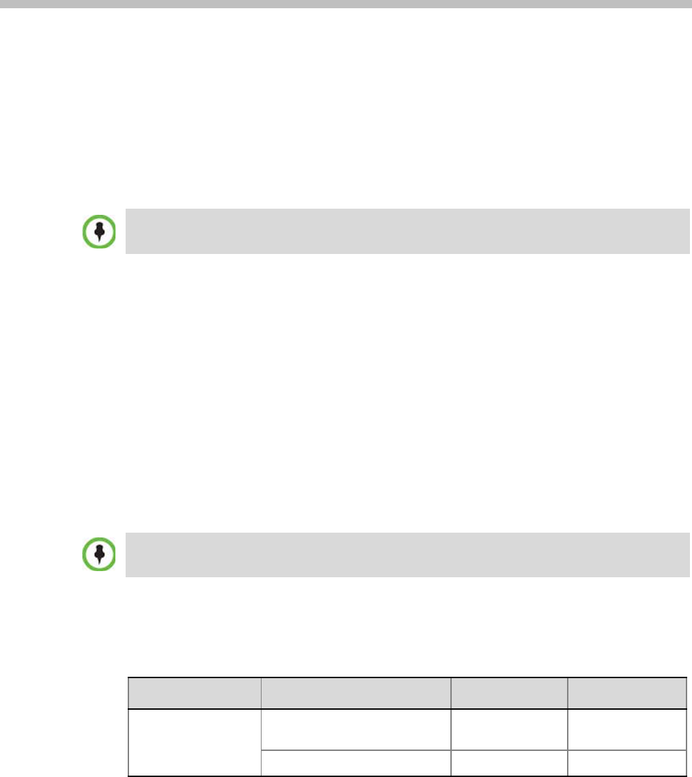
Polycom, Inc. G-1
Appendix G
Setting the Collaboration Server for
Integration Into Microsoft
Environment
Overview
• The Polycom® Visual Communications offers high quality video and audio multipoint
conferencing by integrating the Polycom network devices and endpoints into
Microsoft® platforms. The Polycom® RealPresence® Collaboration Server
(Collaboration Server) system can be integrated into Lync Server 2010 environment
(Microsoft Wave 14).
Point-to-point and multipoint audio and video meetings can be initiated from Lync client,
Windows Messenger and Polycom video endpoints (HDX and VSX) when the environment
components are installed and configured.
• Multipoint calls are enabled when the Collaboration Server is installed in the Microsoft
environment and is configured for unified communications. Routing to conferences can
be performed by the Lync Server by Matched URI dialing - using the SIP URI address.
TLS certificates can be generated using the following methods: CSR, PFX and PEM; each
giving different options for Encryption Key length. Table G-1 lists the SIP TLS Encryption Key
length support for the various system components.
Integration into Microsoft environment (using Lync endpoints) is supported in AVC CP Conferencing
Mode only.
Only TLS connections to the Collaboration Server will work, TCP connections will not work.
The Collaboration Server does not support working with multiple Edge servers.
Table G-1 SIP TLS - Encryption Key Support by System Component
System Component Key Generation Method Key Length (bits) Key generated by
SIP Signaling
CSR 2048 Collaboration
Server
PFX / PEM 1024 or 2048 User

Polycom® RealPresence Collaboration ServerVirtual Edition Administrator’s Guide
G-2 Polycom, Inc.
Conferencing Entities Presence
Conferencing entities (Meeting Rooms, Entry Queues and SIP Factories) can be registered
with the SIP server (Lync server) enabling the addition of these conferencing entities to the
buddy list while displaying their presence (availability status: Available, Offline, or Busy).
Lync Server client users can connect to conferencing entities directly from the buddy list.
The configuration of the environment to enable Presence, is usually done once the basic
configuration is completed.
For more details, see "Adding Presence to Conferencing Entities in the Buddy List” on page G-22.
Management
CSR 2048 Collaboration
Server
LDAP
Table G-1 SIP TLS - Encryption Key Support by System Component (Continued)
System Component Key Generation Method Key Length (bits) Key generated by

Appendix G-Setting the Collaboration Server for Integration Into Microsoft Environment
Polycom, Inc. G-3
Collaboration Server Integration into the Microsoft Lync
Server 2010 and Lync Server 2013 Environments
From Version 7.8, the The RMX interoperability level with Lync 2013 is identical to Lync
2010. Lync 2013 is backward compatible with all RMX Lync 2010 features.
In the Lync Server 2010 environment, only the Matched URI dialing (using the SIP URI
address) is available as the call routing method.
Configuring the Polycom-Microsoft Solution
See the Polycom Unified Communications Deployment Guide for Microsoft Environments,
“Deployment Process for Polycom Collaboration Server Systems” for detailed steps on how to
deploy a Polycom Collaboration Server system for use with the video conferencing solution
in Microsoft Lync Server 2010 environment.
Media Over TCP
Media is automatically transmitted through TCP when UDP, the default transport protocol,
is not available.
The media transport protocol type (UDP/TCP) is displayed in the Participant Properties -
Channel Status - Advanced dialog box.
The media transport protocol type is displayed for the following IP addresses:
• Collaboration Server IP Address
• Participant IP Address
Network Error Recovery
When a short network error occurs, for example 5 seconds, Collaboration Server
automatically recovers, enabling calls in Microsoft Lync to continue the video or audio
conference without disconnecting. However, when a longer network error occurs, the call is
disconnected. The presence status mode is correctly updated from Busy to Available. There is
no configuration required for this procedure.
SIP Dialog Recovery
Collaboration Server has the ability to automatically recover from a SIP dialog failure, which
can occur in long duration calls in Meeting Rooms using the Microsoft Lync client. There is
no configuration required for this procedure.
Non-Lync endpoints connected to the same CP AVC-based conference as Lync endpoints running
on the Collaboration Server, cannot participate in the desktop sharing session initiated by Lync
participants.

Polycom® RealPresence Collaboration ServerVirtual Edition Administrator’s Guide
G-4 Polycom, Inc.
Content Sharing via Polycom CSS (Content Sharing Suite) Plug-in for Lync
Clients
The Polycom CSS (Content Sharing Suite) Plug-in for Lync clients allows Lync clients to
receive and send Content on a separate channel, without having to use the video channel.
Content is transmitted using SIP BFCP. For more details, see "Sharing Content via the Polycom
CSS Plug-in for Lync Clients” on page G-18.
Configuring the Collaboration Server for Microsoft
Integration
The Collaboration Server is integrated in and Microsoft Lync Server environments by
setting its Transport Type (in the SIP server configuration) to TLS and creating a certificate
that is sent to the Collaboration Server. This procedure is also required when encryption of
SIP signaling is used.
In addition, if the DNS server was not enabled in the Network Management Service on the
Collaboration Server, it must be enabled for the integration in the Lync Server (Wave 14)
environments.
Modify the Collaboration Server Management Network Service to Include
the DNS Server
The Management Network that is defined during first entry setup does not include the
definition of the DNS which is mandatory in Microsoft environment and has to be modified.
To add the definition of the DNS to the Management Network in the Collaboration
Server:
1Using the Web browser, connect to the Collaboration Server.
2In the Collaboration Server Management pane, expand the Rarely Used list and click IP
Network Services ().
3In the IP Network Services pane, double-click the Management Service .
The Management Network Properties - IP dialog box opens.
In Multiple Networks configurations, a DNS server can be specified for each IP Network Service and
for the Collaboration Server Management Network Service.
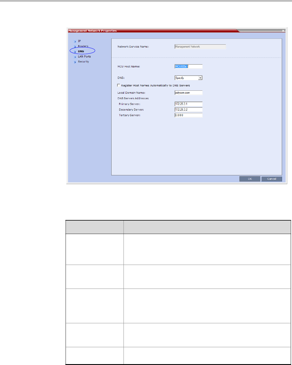
Appendix G-Setting the Collaboration Server for Integration Into Microsoft Environment
Polycom, Inc. G-5
4Click the DNS tab.
5In the DNS field, select Specify to define the DNS parameters.
6View or modify the following fields:
Table 8 Management Network Properties – DNS Parameters
Field Description
MCU Host Name Enter the name of the MCU on the network. This name must be
identical to the FQDN name defined for the Collaboration Server in
the OCS and DNS.
Default name is Collaboration Server.
Shelf Management
Host Name
Displays the name of the entity that manages the Collaboration
Server hardware. The name is derived from the MCU host name.
Default is RMX_SHM.
DNS Select:
•Off – if DNS servers are not used in the network.
•Specify – to enter the IP addresses of the DNS servers.
Note: The IP address fields are enabled only if Specify is selected.
Register Host Names
Automatically to DNS
Servers
Select this option to automatically register the MCU Signaling Host
and Shelf Management with the DNS server.
Local Domain Name Enter the name of the domain where the MCU is installed as defined
in the Office Communications Server/Lync Server.
Polycom® RealPresence Collaboration ServerVirtual Edition Administrator’s Guide
G-6 Polycom, Inc.
7Click OK.
Defining a SIP Network Service in the Collaboration Server and Installing
the Security Certificate
Your RealPresence Collaboration Server system should be installed according to standard
installation procedures. For details, see the Polycom® RealPresence Collaboration Server Virtual
Edition Getting Started Guide.
When configuring the Default IP Network Service on first entry, or when modifying the
properties of the existing Default IP Network Service, the SIP environment parameters must be
set as described in this section.
The Security Certificate
There are two methods to create and send the security certificate that is required for
configuration of the integration of the Collaboration Server in the Microsoft environment:
• The CSR method
• The PFX method (Recommended method for Lync Server, Wave 14)
The CSR Method
In the CSR method, the security certificate is created as part of the SIP Server configuration
in the IP Network Service configuration.
Using the CSR Method, the following processes are performed:
• Creating the certificate request (in the Default IP Network Service - SIP Server dialog box).
• Sending the certificate request to a Certificate Authority.
• Receiving the certificate from the Certificate Authority.
• Installing the certificate in the Collaboration Server (in the Default IP Network Service -
SIP Server dialog box).
The PFX Method
In the PFX method, the security certificate is created in advance, in the Lync Server
environment.
For detailed description of this procedure in the Lync Server environment, see the Polycom
Unified Communications Deployment Guide for Microsoft Environments..
DNS Servers Addresses:
Primary Server The static IP addresses of the DNS servers (the same servers
defined in the Office Communications Server/Lync Server).
A maximum of three servers can be defined.
Secondary Server
Tertiary Server
Table 8 Management Network Properties – DNS Parameters (Continued)
Field Description
Certificates are deleted when an administrator performs a Restore Factory Defaults with the
Comprehensive Restore option selected.
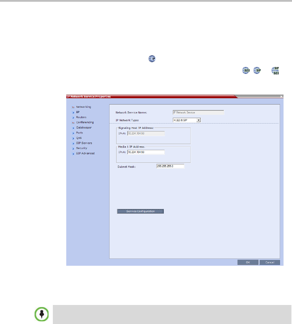
Appendix G-Setting the Collaboration Server for Integration Into Microsoft Environment
Polycom, Inc. G-7
Configuring the Collaboration Server IP Network Service
To configure the Collaboration Server IP Network Service:
1Using the Web browser, connect to the Collaboration Server.
2In the RealPresence Collaboration Server Management pane, expand the Rarely Used list
and click IP Network Services ().
3In the IP Network Services pane, double-click the Default IP Service (, , or )
entry.
The Default IP Service - Networking IP dialog box opens.
4Make sure the IP Network Type is set to H.323 & SIP even though SIP will be the only
call setup used with Office Communications Server 2007.
5Make sure that the correct parameters are defined for the Signaling Host IP Address and
Subnet Mask.
Make sure that the IP address of the Collaboration Server Signaling Host is the same one defined as
a trusted host in Lync Server 2010.
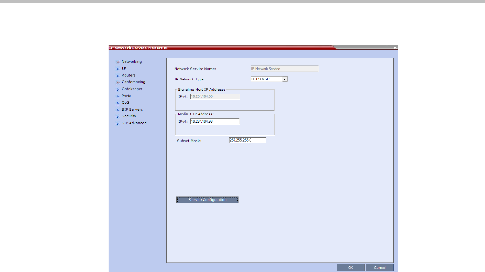
Polycom® RealPresence Collaboration ServerVirtual Edition Administrator’s Guide
G-8 Polycom, Inc.
6Click the SIP Servers tab.
7In the SIP Server, select Specify.
8In the SIP Server Type, select Microsoft.
9Enter the IP address of the Office Communications Server 2007 or Lync Server 2010 and
the Server Domain Name as defined in the OCS/Lync Server and in the Management
Network for the DNS.
10 If not selected by default, change the Transport Type to TLS.
The Create Certificate and Send Certificate buttons are enabled.
11 If you are using the CSR method, and the CSR option is not selected by default, change
the Certificate Method to CSR.
If you are using the PFX method, in the Certificate Method field select PEM/PFX.
At this point the procedure changes according to the selected certificate method.
If you have selected PEM/PFX, skip to step 27 on page G-12.
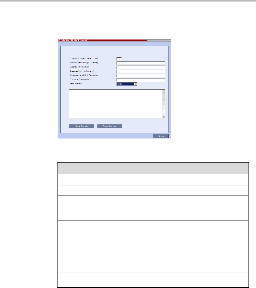
Appendix G-Setting the Collaboration Server for Integration Into Microsoft Environment
Polycom, Inc. G-9
CSR Method - Creating the Certificate
12 Click the Create Certificate button.
The Create Certificate Request dialog box is displayed.
13 Enter information in all the following fields:
14 Click Send Details.
Table G-1 Create Certificate Request
Field Description
Country Name Enter any 2 letter code for the country name.
State or Province Enter the full name of the state or province.
Locality Enter the full name of the town/city/location.
Organization Enter the full name of your organization for which the certificate
will be issued.
Organizational Unit Enter the full name of the unit (group or division) for which the
certificate will be issued.
Common Name (DNS/
IP)
Enter the DNS MCU Host Name. This MCU Host Name must
also be configured in the Management Network Properties
dialog box.
Subject Alternative
Name
Hash Method Select the hash method to be used to hash the certificate
request.
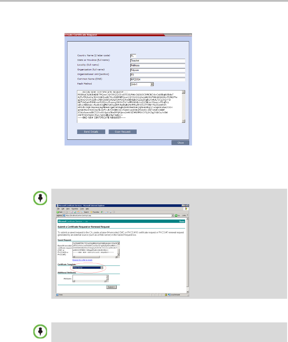
Polycom® RealPresence Collaboration ServerVirtual Edition Administrator’s Guide
G-10 Polycom, Inc.
The Collaboration Server creates a New Certificate Request and returns it to the Create
Certificate Request dialog box along with the information the user submitted.
15 Click Copy Request to copy the New Certificate Request to the workstation’s clipboard.
16 Connect to your preferred Certificate Authority’s website using the web browser.
17 Follow the purchasing instructions at the Certificate Authority’s website.
18 Paste (Ctrl + V) the New Certificate Request as required by the Certificate Authority.
The Certificate Authority issues the TLS/SSL certificate, and sends the certificate to you
by e-mail.
When creating the certificate request in the Certificate Authority site, make sure that the Web Server
option is selected as the Certificate Template, as shown in the example below.
If the process of purchasing the certificate is short, you may leave the IP Network Service - SIP
Servers dialog box open. Otherwise, close it without saving the changes to the Transport Type and
Certificate Method.
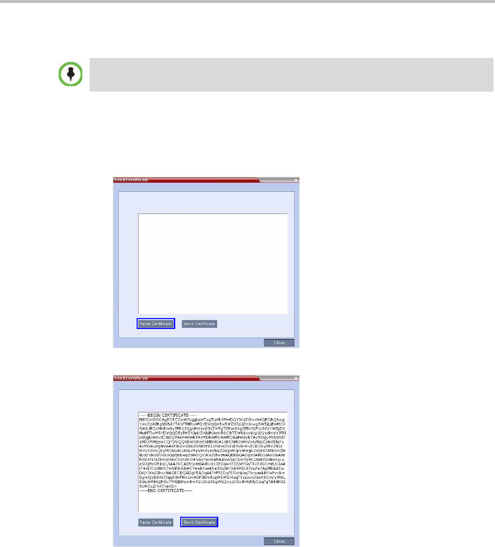
Appendix G-Setting the Collaboration Server for Integration Into Microsoft Environment
Polycom, Inc. G-11
CSR Method - Sending the certificate
After you have received the certificate from the Certificate Authority:
19 Open the Certificate Authority e-mail and Copy (Ctrl + C) the certificate information
from the Certificate Authority’s e-mail to the clipboard.
20 In the IP Network Service - SIP Servers dialog box, click the Send Certificate button.
The Send Certificate dialog box opens.
21 Click Paste Certificate to paste the clipboard content into the Send Certificate dialog box.
22 Click the Send Certificate button to send the certificate to the Collaboration Server.
23 Click the Close button.
24 In the IP Network Service - SIP Servers dialog box, complete the SIP Servers definitions.
25 Click OK.
The MCU validates the certificate.
—If the certificate is not valid, an error message is displayed.
If you have closed the IP Network Service - SIP Servers dialog box, repeat steps 1 to 11 in the
procedure "Defining a SIP Network Service in the Collaboration Server and Installing the Security
Certificate” on page G-6.
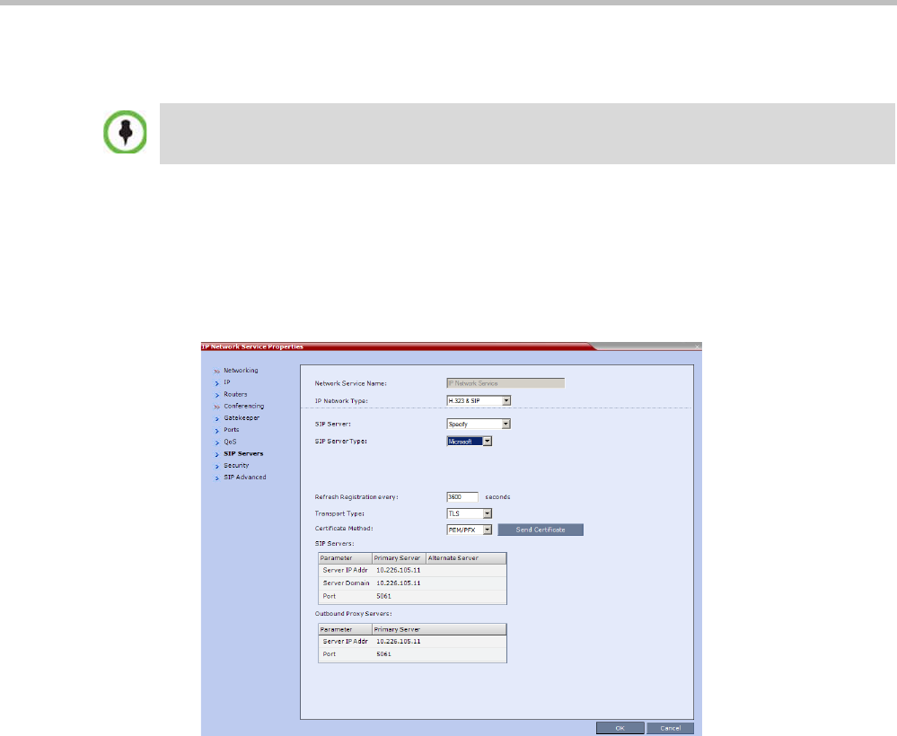
Polycom® RealPresence Collaboration ServerVirtual Edition Administrator’s Guide
G-12 Polycom, Inc.
—If the certificate matches the private key, and the task is completed, a confirmation
message indicating that the certificate was created successfully is displayed.
26 If no additional configuration is required, reset the Collaboration Server.
PFX Method - Sending the Certificate
The PFX certificate request is created in the Lync server. This certificate is received from the
Certificate Authority it can be sent to the Collaboration Server, as described in the following
procedure:
27 Click the Send Certificate button.
The Install File dialog box opens.
Once the certificate is installed in the Collaboration Server you can complete the definition procedure
or continue with the Collaboration Server configuration for ICE dialing. For details, see "” on
page G-32.
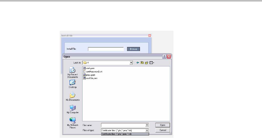
Appendix G-Setting the Collaboration Server for Integration Into Microsoft Environment
Polycom, Inc. G-13
28 Click the Browse button.
The Open dialog box appears, letting you select the certificate file(s) to send to the MCU.
Depending on the method used when the certificate file(s) were created, send the
certificate file(s) to the Collaboration Server according to the contents of the file set that
was created:
—The certificate files pkey.pem, cert.pem and a certPassword.txt. The files were created
by a Certificate Authority and are sent as is to the Collaboration Server together
with the required password contained in the certPassword.txt file.
This is the recommended method.
—The files pkey.pem and cert.pem. The certificate files were created by a Certificate
Authority and are sent as is to the Collaboration Server.
—A *.pfx file and a certPassword.txt file. The file certPassword.txt is manually created if
the *.pfx file was created by the OCS using a password. The *.pfx file will be
converted internally by the Collaboration Server using the password included in
the certPassword.txt into three certificate files named pkey.pem and cert.pem.
—A *.pfx file if the certificate file was created in the OCS without using a password.
The *.pfx file will be converted internally by the Collaboration Server into three
certificate files named pkey.pem and cert.pem.
29 In the file browser, select all files to be sent in one operation according to the contents of
the set:
—One *.pfx file, or
—Two files: one *.pfx file and certPassword.txt, or
—Three files:pkey.pem, cert.pem and certPassword.txt
30 Click Open.
The selected file(s) appear in the Install Files path.
31 Click Install.
The files are sent to the Collaboration Server and the Install File dialog box closes.
32 In the Default IP Service - Networking IP dialog box, click OK.

Polycom® RealPresence Collaboration ServerVirtual Edition Administrator’s Guide
G-14 Polycom, Inc.
33 In the Reset Confirmation dialog box, click No to modify the required system flags before
resetting the MCU, or click Yes if the flag was already set.
Collaboration Server System Flag Configuration
Enabling the Microsoft Environment
The Collaboration Server can be installed in Microsoft R2 environments. To adjust the
Collaboration Server behavior to the Microsoft environment in each release, system flags
must be set.
To configure the system flags on the Polycom Collaboration Server system:
1On the Collaboration Server menu, click Setup > System Configuration.
The System Flags - MCMS_PARAMETERS_USER dialog box opens.
2Scroll to the flag MS_ENVIRONMENT and click it.
The Edit Flag dialog box is displayed.
3In the Value field, enter YES to set the Collaboration Server SIP environment to
Microsoft solution.
4Click OK to complete the flag definition.
5When prompted, click Yes to reset the MCU and implement the changes to the system
configuration. After system reset the Collaboration Server can register to the OCS
server and make SIP calls.
Reset can be performed after setting the system flags (for example, setting the MS_ENVIRONMENT
flag). Sometimes the system fails to read the *.pfx file and the conversion process fails, which is
indicated by the active alarm “SIP TLS: Registration server not responding” and/or “SIP TLS:
Registration handshake failure”. Sending *.pfx file again, as described in this procedure and then
resetting the system may resolve the problem.
Collaboration Server set to MS_ENVIRONMENT=YES supports SIP over TLS only and not over
TCP.
Sometimes the system fails to read the *.pfx file and the conversion process fails, which is indicated
by the active alarm “SIP TLS: Registration server not responding” and/or “SIP TLS: Registration
handshake failure”. Sending *.pfx file again, as described in this procedure and then resetting the
system may resolve the problem.

Appendix G-Setting the Collaboration Server for Integration Into Microsoft Environment
Polycom, Inc. G-15
In some configurations, the following flags may require modifications when
MS_ENVIRONMENT flag is set to YES:
Setting the audio protocol for the Microsoft Client running on a single
core PC
By default, Lync Clients are connected to conferences using the G.722.1 audio algorithm.
However, when these clients are hosted on single processor workstations, they may
experience audio quality problems when this algorithm is used.
The System Flag FORCE_AUDIO_CODEC_FOR_MS_SINGLE_CORE is used to force the
use of a specific Audio algorithm such as G.711 when a Lync Client is detected as being
hosted on a single core processor.
This flag can be set to:
•AUTO – No forcing occurs and the Collaboration Server negotiates a full set of Audio
algorithm during capabilities exchange.
•G711A/U or G722 – Set this flag value according to the hosting workstation capabilities.
If the Collaboration Server detects single core host during capabilities exchange it will
assign a G.711 or G.722 Audio algorithm according to the flag value.
Possible values: AUTO, G711A, G711U, G722
Default: G711A
Table G-2 Additional Microsoft Environment Flags in the Collaboration Server
MCMS_PARAMETERS_USER Tab
Flag Name Value and Description
SIP_FREE_VIDEO_RESOURCES Default value in Microsoft environment: NO.
When set to NO, video resources that were allocated to
participants remain allocated to the participants as long as
they are connected to the conference even if the call was
changed to audio only. The system does not allocate the
resources to other participants ensuring that the participants
have the appropriate resources in case they want to return to
the video call.
The system allocates the resources according to the
participant’s endpoint capabilities, with a minimum of one CIF
video resource.
When this flag is set to YES, video ports are dynamically
allocated or released according to the in the endpoint
capabilities. For example, when an audio Only call is
escalated to Video and vice versa or when the resolution is
changed.
SIP_FAST_UPDATE_INTERVAL_
ENV
Default setting is 0 to prevent the Collaboration Server from
automatically sending an Intra request to all SIP endpoints.
Enter n (where n is any number of seconds other than 0) to
let the Collaboration Server automatically send an Intra
request to all SIP endpoints every n seconds.
It is recommended to set the flag to 0 and modify the
frequency in which the request is sent at the endpoint level
(as defined in the next flag).
Polycom® RealPresence Collaboration ServerVirtual Edition Administrator’s Guide
G-16 Polycom, Inc.
Microsoft RTV (Real Time Video) protocol provides high quality video conferencing capability
to Microsoft OC (Office Communicator) Client endpoints at resolutions up to HD720p30.
Interoperability between Polycom HDX and OCS endpoints is improved.
Guidelines
•The RTV protocol is supported:
—In SIP networking environments only
—In CP mode only
•OCS (Wave 13) and Lync Server (Wave 14) clients are supported.
•RTV is supported in Basic Cascade mode.
•RTV is the default protocol for OCS endpoints and Lync Server clients connecting to a
conference.
•RTV participants are supported in recorded conferences.
•RTV participant encryption is supported using the SRTP protocol.
•Video Preview is not supported for RTV endpoints.
•Custom Slides in IVR Services are not supported for RTV endpoints.
•HD720p30 resolution is supported at bit rates greater than 600 kbps. The following table
summarizes the resolutions supported at the various bit rates.
* Dependant on the PC’s capability
•System Resource usage is the same as for the H.264 protocol. Table G-4 summarizes
System Resource usage for each of the supported resolutions.
Table G-3 RTV - Resolution by Bit Rate
Resolution Bitrate
QCIF Bitrate <180kbps
CIF30 180kbps < Bitrate < 250kbps
VGA (SD30) 250kbps < Bitrate < 600kbps *
HD720p30 600kbps < Bitrate *
Table G-4 RTV - Resources by Resolution
Resolution HD Video Resources Used
QCIF / CIF30 0.333
VGA (SD30) / W4CIF 0.5
HD720p30 1

Appendix G-Setting the Collaboration Server for Integration Into Microsoft Environment
Polycom, Inc. G-17
Participant Settings
When defining a new participant or modifying an existing participant, select SIP as the
participant’s networking environment Type in the
New Participant
or
Participant Properties -
General tab.
The participants Video Protocol in the
New Participant
or
Participant Properties -
Advanced tab
should be left at (or set to) its default value: Auto.
The Auto setting allows the video protocol to be negotiated according to the endpoint’s
capabilities:
•OCS endpoints and Lync Server clients connect to the conference using the RTV
protocol.
• Other endpoints negotiate the video protocol in the following sequence: H.264,
followed by RTV, followed by H.263 and finally H.261.
Protocol Forcing
Selecting H.264, RTV, H.263 or H.261 as the Video Protocol results in endpoints that do not
support the selected Video Protocol connecting as Secondary (audio only).
SIP
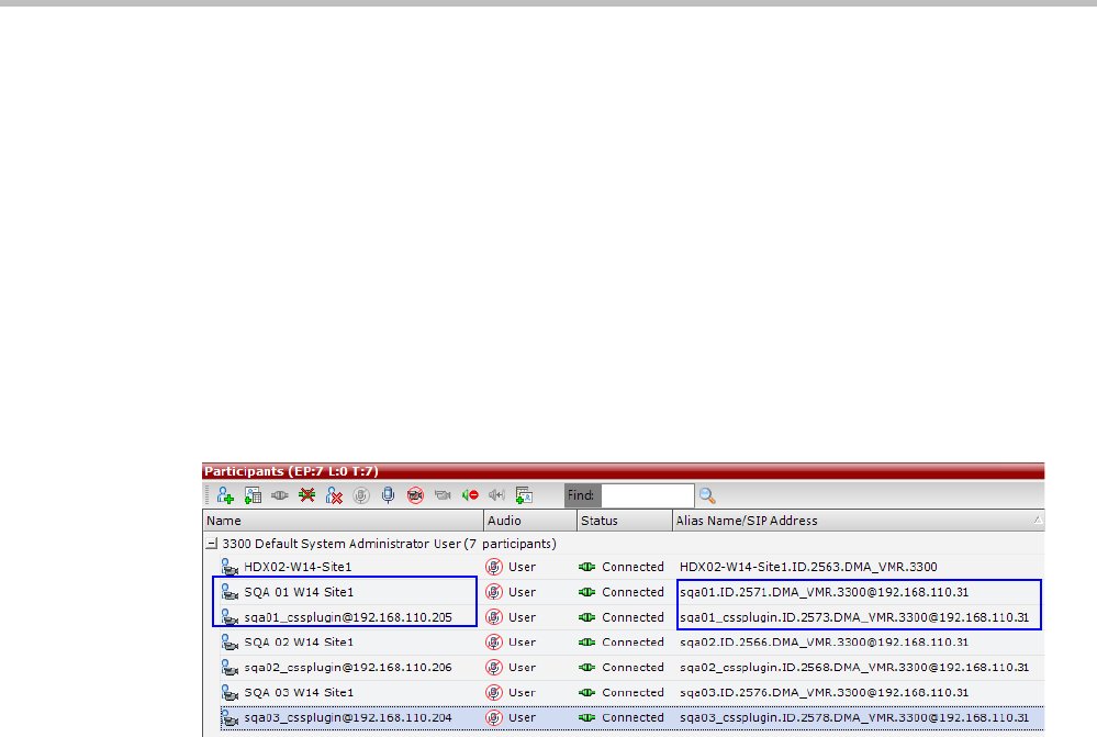
Polycom® RealPresence Collaboration ServerVirtual Edition Administrator’s Guide
G-18 Polycom, Inc.
Sharing Content via the Polycom CSS Plug-in for Lync
Clients
From version 8.1, Polycom CSS (Content Sharing Suite) Plug-in for Lync clients allows Lync
clients to receive and send Content on a separate channel, without having to use the video
channel. Content is transmitted using SIP BFCP.
When Lync clients connect, each endpoint is represented twice in the RMX Manager or
Collaboration Server Web Client. One connection represents the actual Lync client, while the
second connection represents the content channel via the Polycom plug-in.
The name of the plug-in “participant” is derived from the name of the Lync client with the
suffix “_cssplugin”.
When a Lync client connects to a conference, the plug-in connects automatically, regardless
of whether the Lync client dials into a conference or is called from the MCU.
Guidelines
• The maximum resolution for content sharing via the Polycom CSS plug-in is HD720p5.
• The Polycom CSS plug-in supports H.263 and H.264 video protocols for content
sharing.
• SVC-enabled endpoints use the AVC (H.264) protocol for sharing content.
• Content can be shared between different types of endpoints, using different network
protocols (H.323, SIP and ISDN/PSTN).
•TIP content is not supported.
• Lync 2013 is supported.
•ICE is not supported.
Configuring the MCU for Content Sharing via the Polycom CSS Plug-in
You can configure the MCU for content sharing via the Polycom CSS plug-in by setting the
following parameters:
• Setting the BLOCK_CONTENT_LEGACY_FOR_LYNC system flag
• Setting the Content parameters in the conference Profile

Appendix G-Setting the Collaboration Server for Integration Into Microsoft Environment
Polycom, Inc. G-19
Setting the System Flag
By configuring the system flag BLOCK_CONTENT_LEGACY_FOR_LYNC you control the
system behavior in an environment where some Lync clients use the Polycom CSS plug-in
and some do not. This flag must be manually added to the system configuration to change
its value.
• When set to NO (default), Content is sent to all Lync clients over the video channel,
including those with the Polycom CSS plug-in installed, even when the Send Content to
Legacy Endpoints is disabled.
Other, non-Lync legacy endpoints will not be affected by this flag and will receive
content according to the Send Content to Legacy Endpoints settings in the conference
Profile.
• When set to YES, Content is not sent to Lync clients over the video channel including
those with the Polycom CSS plug-in installed, even when the Send Content to Legacy
Endpoints is enabled.
Other, non-Lync legacy endpoints will not be affected by this flag and will receive
content according to the Send Content to Legacy Endpoints settings in the conference
Profile.
Conference Profile Settings
Content is shared in a video switching mode. Therefore, when a Lync client connects to the
conference via the Polycom CSS plug-in, the content resolution will be adjusted to the
maximum content rate possible by the Lync client, up to a maximum of 720p 5fps in all line
rates, even if you select a higher content rate and resolution in the Conference Profile.
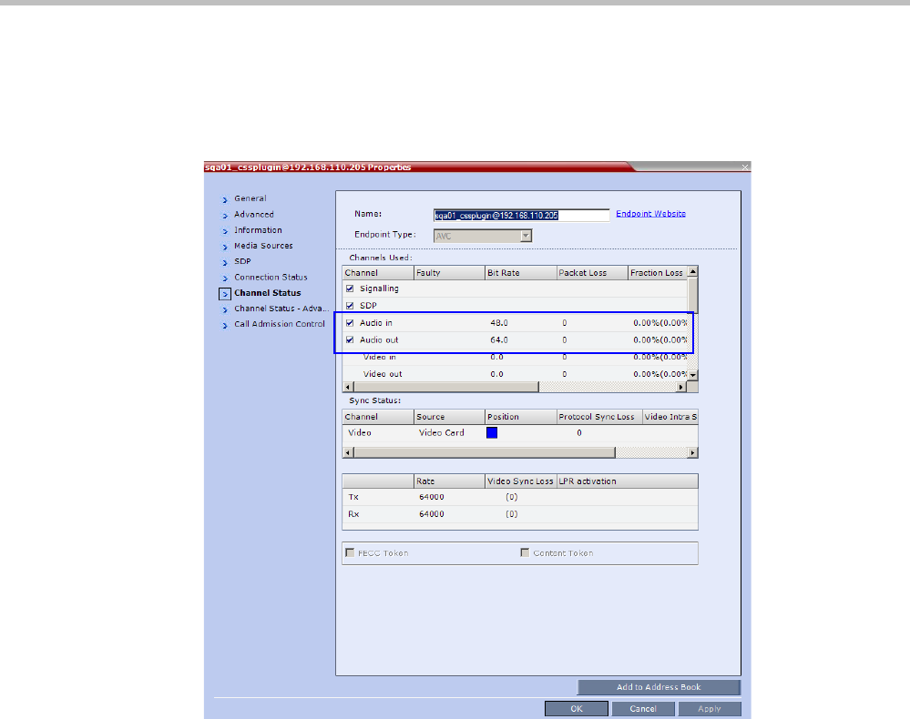
Polycom® RealPresence Collaboration ServerVirtual Edition Administrator’s Guide
G-20 Polycom, Inc.
Monitoring the Participant connection
• Under properties of the participant representing the CSS plug-in, Channel Status, audio
channels are shown, but audio is not used in the plug-in. The information can be
ignored.
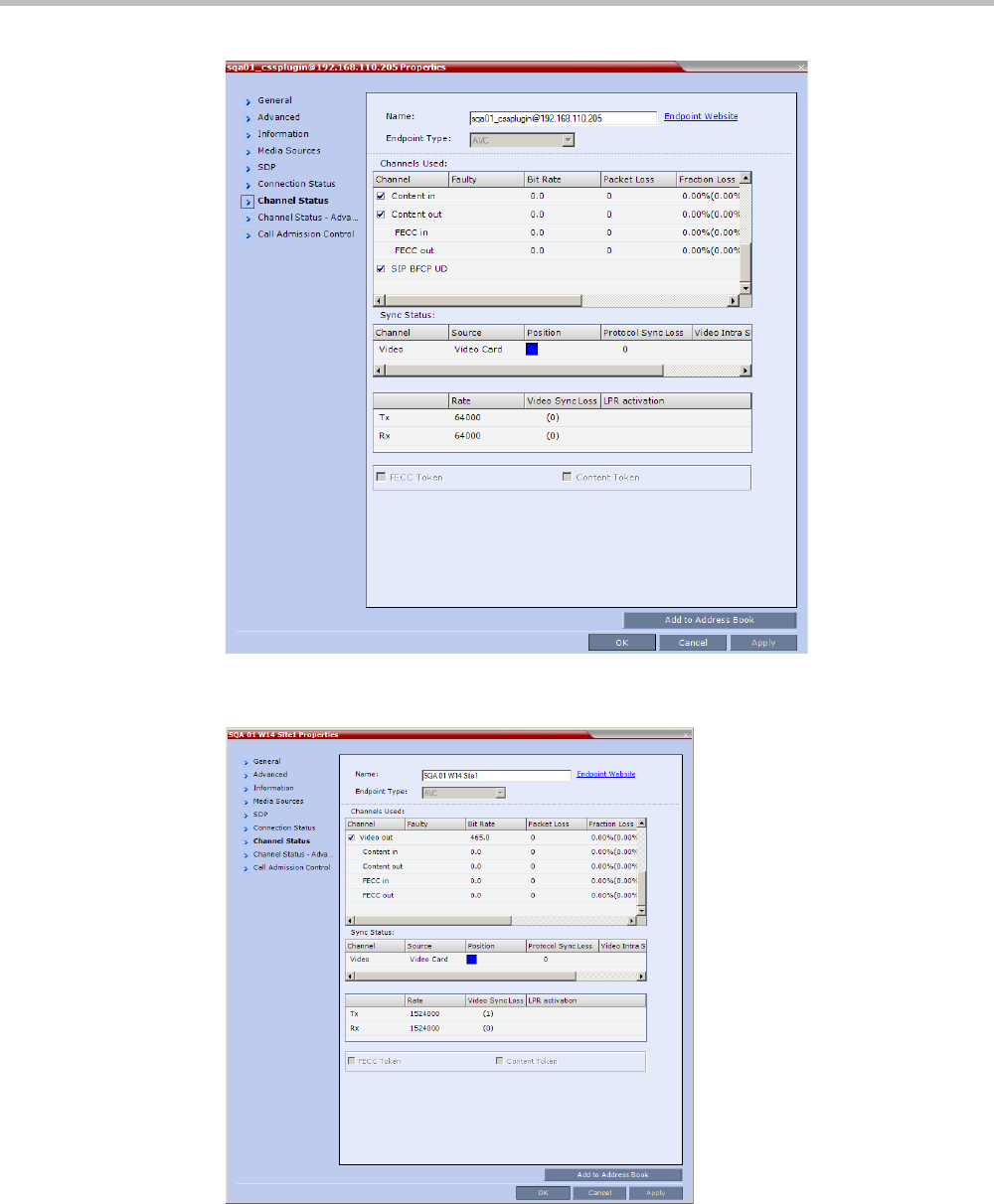
Appendix G-Setting the Collaboration Server for Integration Into Microsoft Environment
Polycom, Inc. G-21
• The properties of the Lync client are those of a video participant. However, the Content
channel will show 0 as there is no content channel.
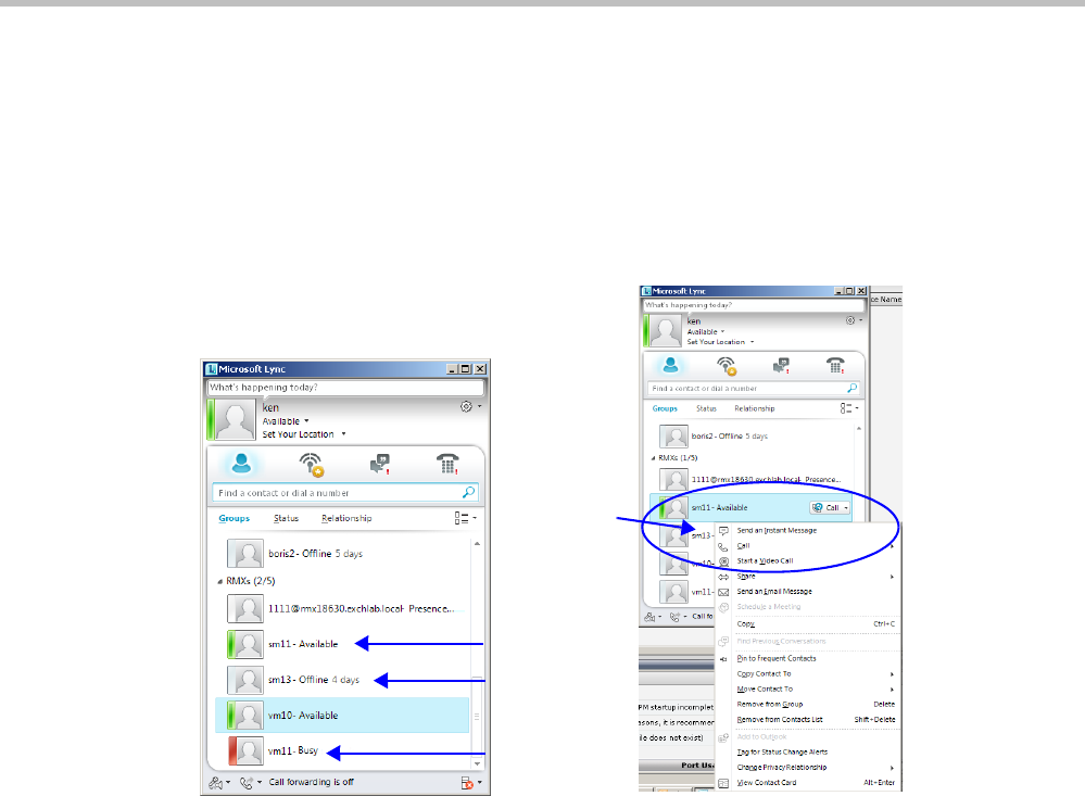
Polycom® RealPresence Collaboration ServerVirtual Edition Administrator’s Guide
G-22 Polycom, Inc.
Adding Presence to Conferencing Entities in the Buddy
List
Registration of conferencing entities (Meeting Rooms, Entry Queues and SIP Factories) with
the SIP server adds these conferencing entities to the buddy list with their presence. It
enables the LYNC Server client users to see the availability status (Available, Offline, or
Busy) of these conferencing entities and connect to them directly from the buddy list.
Guidelines
• Registration with Presence of up to 100 conferencing entities to a single SIP Server is
supported. When this number is exceeded, the additional conferencing entity may
appear to be successfully registered but the presence status will be shown as 'Offline' in
Lync for any entities beyond the limit.
• Lync endpoints cannot connect to conferencing entities that their presence is “offline”.
• The Conferencing Entity: Meeting Room, Entry Queue, SIP Factory (Routing Name) has
to be added to the Active Directory as a User.
Make sure that a unique name is assigned to the conferencing entity and it is not
already used for another user account in the Active Directory.
• The conferencing entity name must not include any upper case letters or special
characters: @ # $ % ^ & * ( ) _ - = + | } { : " \ ] [ ; / ? > < , . (space) ~.
• When the MCU system is shutting down while a Meeting Room is still active, as
indicated by its presence, the status remains active for 10 minutes during which Lync
endpoints cannot connect to the Meeting Room. After 10 minutes, the Meeting Room
Status changes to “offline”.
• Registration of the conferencing entity is defined in the Conference Profile (and not in
the IP Network Service), enabling you to choose the conferencing entity to register.
conferencing
entity status:
Available
Offline
Busy
Right-click the
conferencing
entity and then
select Call or
Start a Video
Call
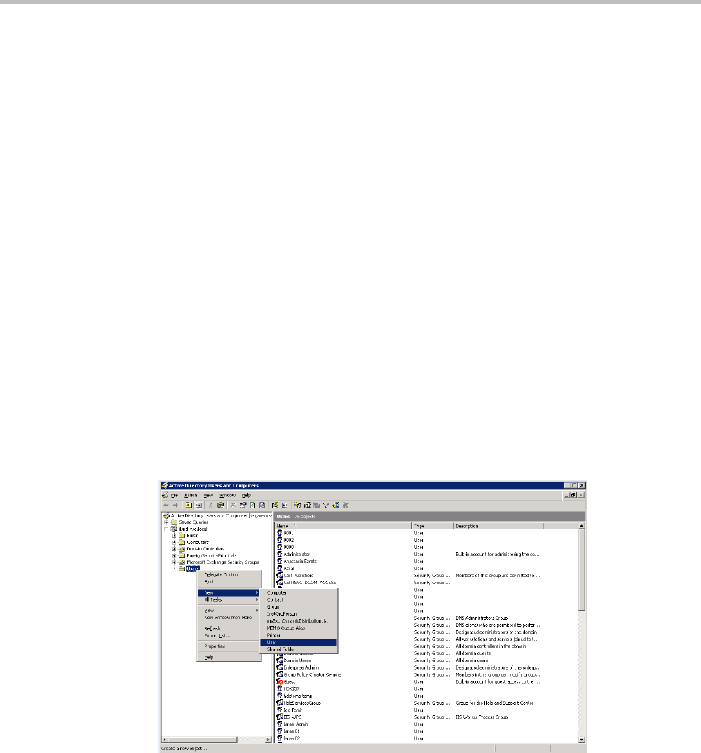
Appendix G-Setting the Collaboration Server for Integration Into Microsoft Environment
Polycom, Inc. G-23
•In Multiple Networks configuration, an IP Network Service that is enabled for
registration in a Conference Profile cannot be deleted.
Enabling the Registration of the Conferencing Entities
The creation of the various conferencing entities is described in the following chapters:
•"Meeting Rooms” on page 6-1
•"Entry Queues, Ad Hoc Conferences and SIP Factories” on page 7-1
Registration with presence of conferencing entities with the SIP Server is enabled by
performing the following processes:
• Creating an Active Directory Account for the Conferencing Entity.
• Enabling the Conferencing Entity User Account for Lync Server
• Defining the Microsoft SIP Server in the IP Network Service
• Enabling Registration in the Conference Profile
Creating an Active Directory Account for the Conferencing Entity
The User account created for the Conferencing entity is used for registration with the Lync
server and to automatically synchronize with the STUN and relay (Edge) servers.
To add the conferencing entity user to the Active Directory:
1Go to Start > Run and enter dsa.msc to open the Active Directory Users and Computers
console.
2In the console tree, select Users > New > User.
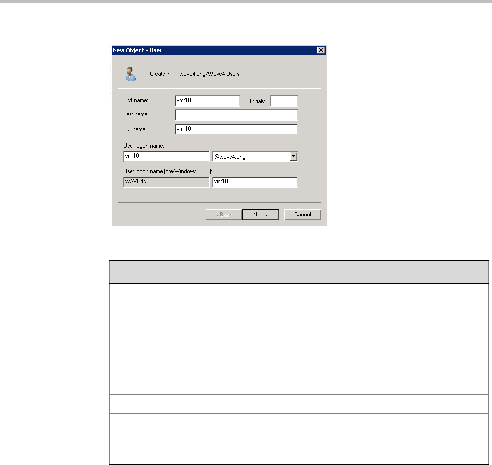
Polycom® RealPresence Collaboration ServerVirtual Edition Administrator’s Guide
G-24 Polycom, Inc.
3In the New User wizard, define the following parameters:
4Click Next.
5Enter the password that complies with the Active Directory conventions and confirm
the password.
6Select the options: User cannot change password and Password never expires.
Clear the other options.
7Click Next.
The system displays summary information.
8Click Finish.
The new User is added to the Active Directory Users list.
9Repeat for each Collaboration Server conferencing entity.
Table G-5 Active Directory - New User Parameters for the Collaboration Server
Field Description
First Name Enter the name of the conferencing entity user. This name will
appear in the buddy list of the Office Communication Server or Lync
server. For example, vmr10.
Notes:
•This name must be the identical to the Routing Name assigned
to the conferencing entity in the Collaboration Server system. It
must also be the User Login Name in the Active Directory.
•The name can include only lower case characters and/or
numbers.
Full Name Enter the same name as entered in the First Name field.
User Login Name Enter the same name as entered in the First Name field and select
from the drop down list the domain name for this user. It is the
domain name defined for the Office Communication Server or Lync
server.
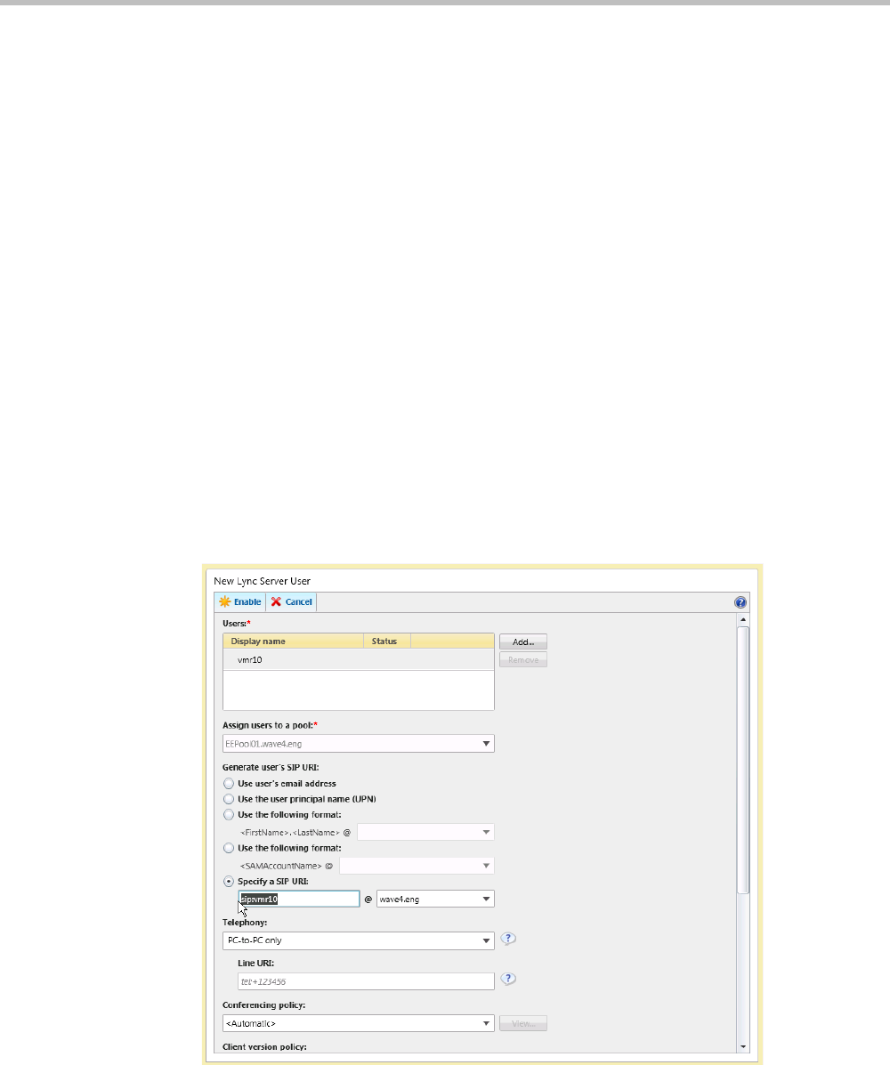
Appendix G-Setting the Collaboration Server for Integration Into Microsoft Environment
Polycom, Inc. G-25
Enabling the Conferencing Entity User Account for Lync Server
The new Conferencing Entity user must be enabled for registration with the Lync Server.
To enable the Conferencing Entity User Account for Lync Server:
1On the computer running the Lync Server 2010, go to Start->All Programs->Microsoft
Lync Server 2010>Lync Server Control Panel.
Windows Security window opens.
2Enter your User name and Password as configured in the Lync Server and click OK.
The Microsoft Lync Server 2010 Control Panel window opens.
3Click the Users tab.
4In the User Search pane, click the Enable Users heading.
The New Lync Server User pane opens.
5Click the Add button.
The Select from Active Directory dialog box opens.
6Enter the conferencing entity user name as defined in the Active Directory, and then
click the Find button.
The requested user is listed in the Select From Active Directory dialog box.
7Select the listed user (conferencing entity user) and click OK.
The selected user appears in the New Lync Server User pane.
8Select the following parameters:

Polycom® RealPresence Collaboration ServerVirtual Edition Administrator’s Guide
G-26 Polycom, Inc.
— In Assign users to a pool field, select the required pool.
—In the Generate user SIP URI, define the SIP URI of the conferencing entity using one
of the following methods:
• Select the Specify a SIP URI option and enter the conferencing entity user
portion of SIP URI defined in the active directory. This SIP URI must match the
conferencing entity Routing Name configured in Collaboration Server. For
example, for the meeting room account sip:vmr10@wave4.eng, use only the
vmr10 portion of the address.
or
• Select the Use the user principal name (UPN) option.
9Click the Enable button.
The selected user appears as enabled in the User Search pane.
Defining the Microsoft SIP Server in the IP Network Service
To enable the registration of the conferencing entities the SIP Server Type must be set to
Microsoft and the Lync Server properties in the IP Network Service - SIP Servers dialog box.
For more details, see "Configuring the Collaboration Server IP Network Service” on page G-7.
Enabling Registration in the Conference Profile
Registration of conferencing entities such as ongoing conferences, Meeting Rooms, Entry
Queues, SIP Factories and Gateway Sessions with SIP servers is done per conferencing entity.
This allows better control on the number of entities that register with each SIP server.
Selective registration is enabled by assigning a conference Profile in which registration is
enabled to the conferencing entities that require registration. Assigning a conference Profile
in which registration is disabled (registration check box is cleared) to conferencing entities
will prevent them from registering. By default, Registration is disabled in the Conference
Profile, and must be enabled in Profiles assigned to conferencing entities that require
registration.
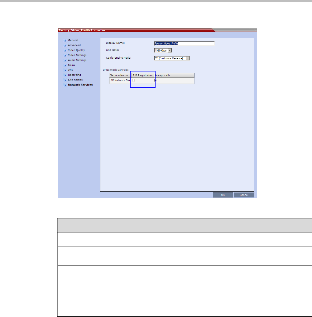
Appendix G-Setting the Collaboration Server for Integration Into Microsoft Environment
Polycom, Inc. G-27
Registration can be enabled in the New Profile - Network Services dialog box:
Verifying the Collaboration Server Conferencing Entity Routing Name
and Profile
Collaboration Server conferencing entity can be dialed directly from the buddy list of the
Lync client if its routing name matches the user name of Active Directory account you created
and Registration is enabled in the Conference Profile assigned to it.
Table G-6 Profile Properties - Network Services
Parameter Description
IP Network Services:
Service Name This column lists all the defined Network Services, one or several depending
on the system configuration (single Network or Multiple Networks).
SIP Registration To register the conferencing entity to which this profile is assigned, with the
SIP Server defined for that Network Service, click the SIP Registration check
box of that Network Service.
Accept Calls To prevent dial in participants from connecting to a conferencing entity when
connecting via a certain Network Service, clear the Accept Calls check box
of that Network Service.
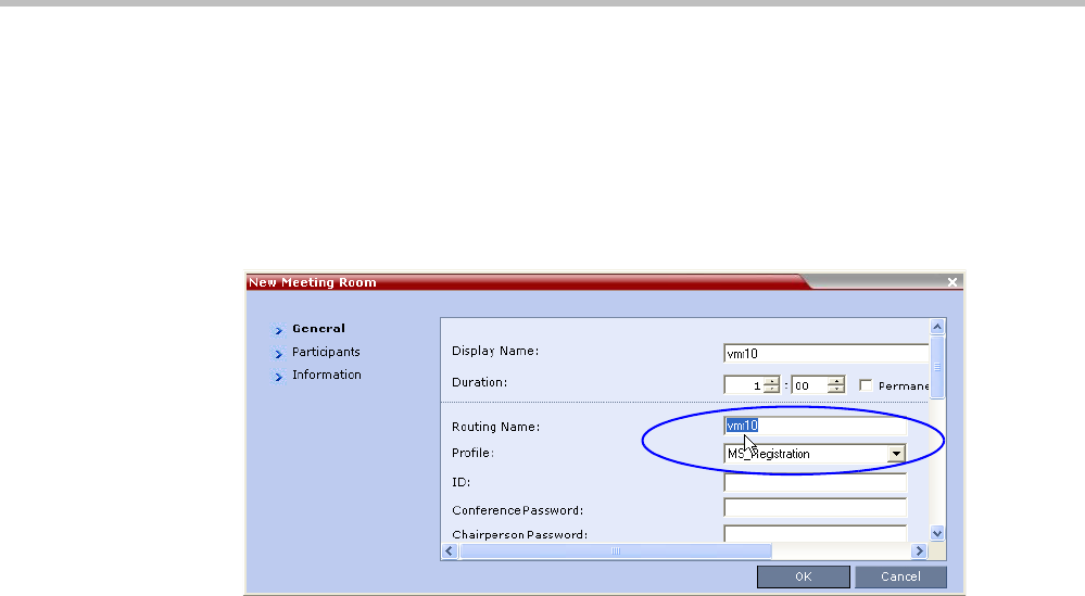
Polycom® RealPresence Collaboration ServerVirtual Edition Administrator’s Guide
G-28 Polycom, Inc.
• To ensure that the Collaboration Server meeting room or conferencing entity is
properly configured for registration the following parameters must be defined:
— The user name on the conferencing entity in Active Directory account must be
identical to its Routing Name on the Collaboration Server.
For example, if the SIP URI in the Active Directory is
sip:vmr10@wave4.eng
, it must
be defined as
vmr10
in the Routing Name field of that Collaboration Server
conferencing entity.
—In the Profile field, make sure that a conference Profile that has been enabled for SIP
registration is selected.
Monitoring the Registration Status of a Conferencing Entity in the
Collaboration Server Web Client or RMX Manager Application
The Status of the SIP registration can be viewed in the appropriate conferencing Entity list
or when displaying its properties.
Conferencing Entity List
The list of conferencing entity includes an additional column - SIP Registration, which
indicates the status of its registration with the SIP server. The following statuses are
displayed:
•Not configured - Registration with the SIP Server was not enabled in the Conference
Profile assigned to this conferencing Entity. In Multiple Networks configuration, If one
service is not configured while others are configured and registered, the status reflects
the registration with the configured Network Services. The registration status with each
SIP Server can be viewed in the Properties - Network Services dialog box of each
conferencing entity.
When SIP registration is not enabled in the conference profile, the Collaboration
Server's registering to SIP Servers will each register with an URL derived from its own
signaling address. This unique URL replaces the non-unique URL, dummy_tester, used
in previous versions.
•Failed - Registration with the SIP Server failed.
This may be due to incorrect definition of the SIP server in the IP Network Service, or
the SIP server may be down, or any other reason the affects the connection between the
Collaboration Server or the SIP Server to the network.
•Registered - the conferencing entity is registered with the SIP Server.
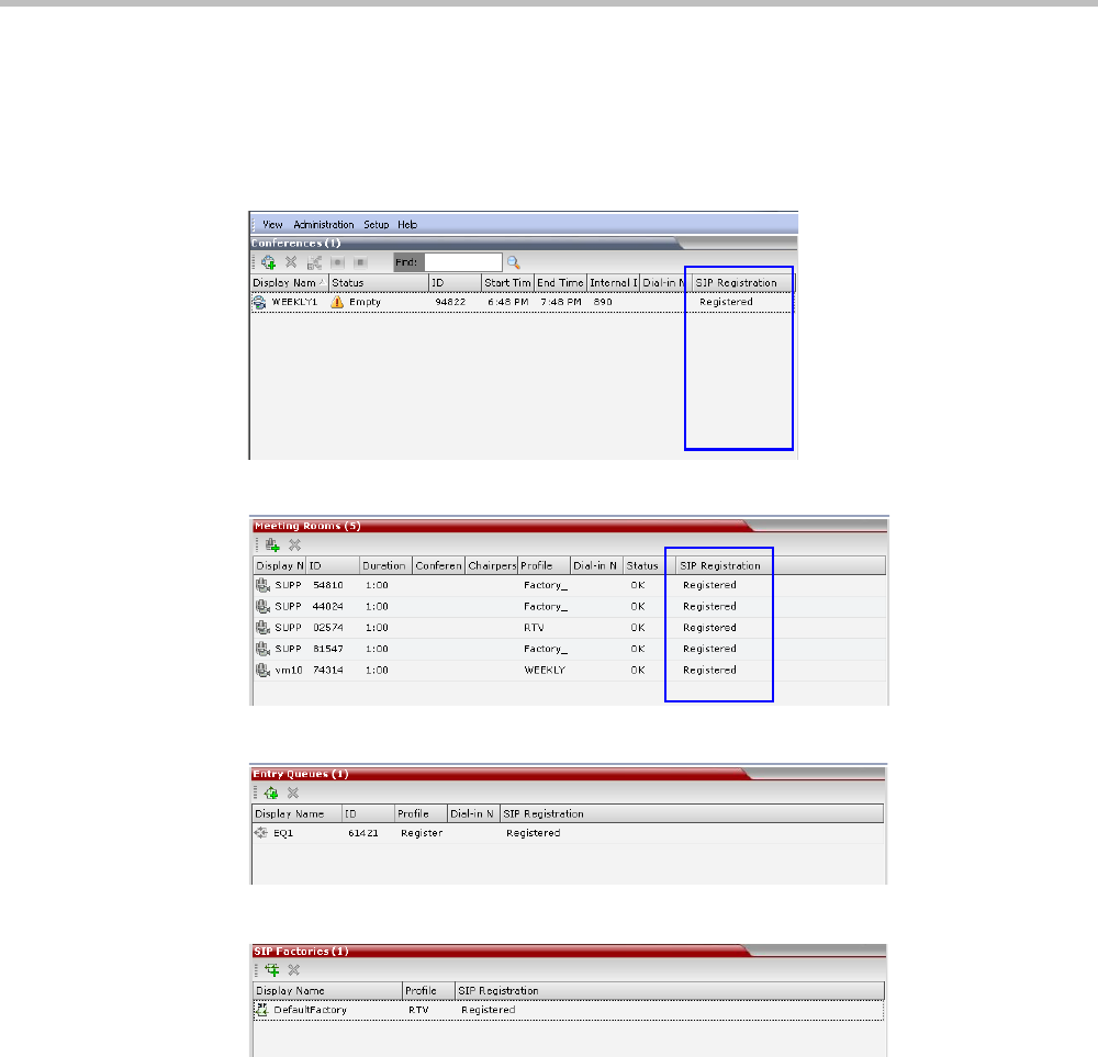
Appendix G-Setting the Collaboration Server for Integration Into Microsoft Environment
Polycom, Inc. G-29
•Partially Registered - This status is available only in Multiple Networks configuration,
when the conferencing entity failed to register to all the required Network Services (if
more than one Network Service was selected for Registration). The registration status
with each SIP Server can be viewed in the Properties - Network Services dialog box of each
conferencing entity.
Figure G-1 Ongoing Conferences list - SIP Registration
Figure G-2 Meeting Rooms list - SIP Registration
Figure G-3 Entry Queues list - SIP Registration
Figure G-4 SIP Factories list - SIP Registration
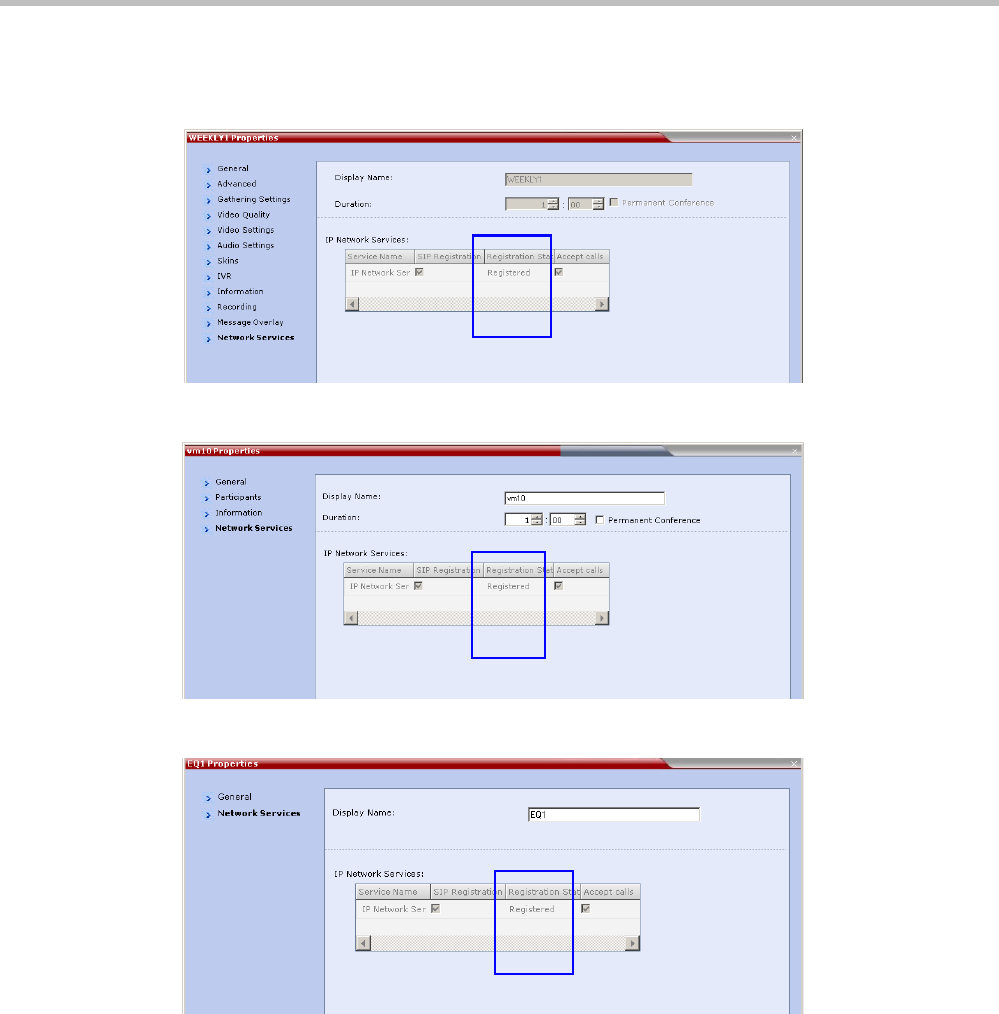
Polycom® RealPresence Collaboration ServerVirtual Edition Administrator’s Guide
G-30 Polycom, Inc.
Conferencing Entity Properties
Registration status is reflected in the Properties - Network Services dialog box:
Figure G-5 Ongoing conference Properties - Network Services - SIP Registration
Figure G-6 Meeting Room Properties - Network Services - SIP Registration
Figure G-7 Entry Queue Properties - Network Services - SIP Registration
Appendix G-Setting the Collaboration Server for Integration Into Microsoft Environment
Polycom, Inc. G-31
Connecting a Collaboration Server Meeting Room to a
Microsoft AV-MCU Conference
Microsoft Lync users can connect an Collaboration Server Meeting Room to a conference
running on the Microsoft A/V MCU. This allows Collaboration Server Lync users to connect
with a conference in progress on the A/V MCU and be an active participant in the
conference. The connection to the A/V MCU is the same configuration as a cascading
conference between multiple Collaboration Server MCUs.
To connect to an A/V MCU conference:
1From the Menu bar, click Meet Now to create an ad-hoc conference.
The Group Conversation dialog box is displayed.
2From the Contacts List on Lync, drag a Virtual Meeting Room (VMR) into the Group
Conversation list.
After the Virtual Meeting Room is connected on Lync, an invitation is sent from the A/V
MCU to the Collaboration Server using the Centralized Conference Control Protocol
(CCCP). The Collaboration Server responds and triggers a standard SIP invite sent from the
A/V MCU to the Collaboration Server.
Multiple participants can now connect to both the Collaboration Server Meeting Room and
the A/V MCU, and participate in a cascaded conference.
When a conference begins with Audio Only, a Lync user cannot add video to the conference after
the VMR is connected to the conference. The conference will remain as Audio Only.

Polycom® RealPresence Collaboration ServerVirtual Edition Administrator’s Guide
G-32 Polycom, Inc.
Active Alarms and Troubleshooting
Active Alarms
The following active alarms may be displayed in the Collaboration Server System Alerts
pane when the Collaboration Server is configured for integration in the OCS environment:
Table G-7 New Active Alarms
Alarm Code Alarm Description
SIP TLS: Failed to load or verify
certificate files
This alarm indicates that the certificate files required for SIP TLS
could not be loaded to the Collaboration Server. Possible causes
are:
•Incorrect certificate file name. Only files with the following
names can be loaded to the system: rootCA.pem, pkey.pem,
cert.pem and certPassword.txt
•Wrong certificate file type. Only files of the following types
can be loaded to the system: rootCA.pem, pkey.pem and
cert.pem and certPassword.txt
•The contents of the certificate file does not match the system
parameters
SIP TLS: Registration transport
error
This alarm indicates that the communication with the SIP server
cannot be established. Possible causes are:
•Incorrect IP address of the SIP server
•The SIP server listening port is other than the one defined in
the system
•The OCS services are stopped
Note:
Sometimes this alarm may be activated without real cause.
Resetting the MCU may clear the alarm.
SIP TLS: Registration
handshake failure
This alarm indicates a mismatch between the security protocols
of the OCS and the Collaboration Server, preventing the
Registration of the Collaboration Server to the OCS.

Appendix G-Setting the Collaboration Server for Integration Into Microsoft Environment
Polycom, Inc. G-33
Troubleshooting
• At the end of the installation and configuration process, to test the solution and the
integration with the OCS, create an ongoing conference with two participants, one dial-
in and one dial-out and connect them to the conference.
•If the active Alarm “SIP TLS: Registration server not responding” is displayed, stop and
restart the OCS Pool Service.
• If the communication between the OCS and the Collaboration Server cannot be
established, one of the possible causes can be that the Collaboration Server FQDN name
is defined differently in the DNS, OCS and Collaboration Server. The name must be
defined identically in all three devices, and defined as type A in the DNS. The definition
of the Collaboration Server FQDN name in the DNS can be tested by pinging it and
receiving the Collaboration Server signaling IP from the DNS in return.
• The communication between the OCS and the Collaboration Server can be checked in
the Logger files:
—SIP 401/407 reject messages indicate that the Collaboration Server is not
configured as Trusted in the OCS and must be configured accordingly.
—SIP 404 reject indication indicates that the connection to the OCS was established
successfully.
SIP TLS: Registration server not
responding
This alarm is displayed when the Collaboration Server does not
receive a response from the OCS to the registration request in
the expected time frame. Possible causes are:
•The Collaboration Server FQDN name is not defined in the
OCS pool, or is defined incorrectly.
•The time frame for the expected response was too short and
it will be updated with the next data refresh. The alarm may
be cleared automatically the next time the data is refreshed.
Alternatively, the OCS Pool Service can be stopped and
restarted to refresh the data.
•The Collaboration Server FQDN name is not defined in the
DNS server. Ping the DNS using the Collaboration Server
FQDN name to ensure that the Collaboration Server is
correctly registered to the DNS.
SIP TLS: Certificate has expired The current TLS certificate files have expired and must be
replaced with new files.
SIP TLS: Certificate is about to
expire
The current TLS certificate files will expire shortly and will have
to be replaced to ensure the communication with the OCS.
SIP TLS: Certificate subject
name is not valid or DNS failed
to resolve this name
This alarm is displayed if the name of the Collaboration Server in
the certificate file is different from the FQDN name defined in the
OCS.
Note:
Occasionally this alarm may be activated without real cause.
Resetting the MCU may clear the alarm.
Table G-7 New Active Alarms (Continued)
Alarm Code Alarm Description

Polycom® RealPresence Collaboration ServerVirtual Edition Administrator’s Guide
G-34 Polycom, Inc.
Known Issues
• Selecting Pause my Video in OC client causes the call to downgrade to audio only call if
the call was not in Audio Only mode at all (the call was started as a video call).
If the call is started as an audio only call and video is added to it, or if the call was
started as video call and during the call it was changed to Audio Only and back to
video, selecting Pause my Video will suspend it as required.
• Rarely, the OC client disconnects after 15 minutes. The OC client can be reconnected
using the same dialing method in which they were previously connected (dial-in or
dial-out).
• Rarely, all SIP endpoints disconnect at the same time. The SIP endpoint can be
reconnected using the same dialing method in which they were previously connected
(dial-in or dial-out).
Polycom Solution Support
Polycom Implementation and Maintenance services provide support for Polycom solution
components only. Additional services for supported third-party Unified Communications
(UC) environments integrated with Polycom solutions are available from Polycom Global
Services and its certified Partners. These additional services will help customers successfully
design, deploy, optimize and manage Polycom visual communications within their UC
environments.
Professional Services for Microsoft Integration is mandatory for Polycom Conferencing for
Microsoft Outlook and Microsoft Office Communications Server integrations. For additional
information and details please see http://www.polycom.com/services/
professional_services/index.html or contact your local Polycom representative.

Polycom, Inc. H-1
Appendix H
SIP RFC Support
Table H-1 SIP RFC Support in RealPresence Collaboration Server Systems
SIP RFC Description Note
1321 MD5
2032 RTP Payload for H.261
2205 RSVP
2327 Session Description Protocol (SDP)
2429 RTP Payload for H.263+
2833 RTP Payload for DTMF
2617 HTTP Authentication
2976 SIP Info Method
3261 SIP
3264 Offer/Answer Model
3265 SIP Specific Event Notification Limited support
3311 SIP Update Method
3515 SIP Refer Method Limited support
3550 RTP
3551 RTP Profile for Audio/Video
3711 SRTP
3890 Transport Independent Bandwidth Modifier
for SDP
3891 SIP Replaces header Limited support
3892 SIP Referred-by Mechanism Limited support
3984 RTP Payload format for H.264
4028 Session Timers in SIP
4145 TCP Media Transport in SDP
4566 Session Description Protocol (SDP)

RealPresence Collaboration Server Virtual Edition Administrator’s Guide
H-2 Polycom, Inc.
4568 SDP Security Descriptions
4573 H.224 RTP Payload (FECC)
4574 SDP Label Attribute
4582 Binary Floor Control Protocol (BFCP)
4583 SDP for BFCP
4796 SDP Content Attribute
5168 XML Schema for Media Control (Fast
Update)
cc-transfer Call Transfer Capabilities in SIP Limited support
draft-turn-07 TURN spec for firewall traversal in SIP
draft-rfc3489bis-15 STUN spec for firewall traversal in SIP
Table H-1 SIP RFC Support in RealPresence Collaboration Server Systems (Continued)
SIP RFC Description Note
