Porsche 944 Workshop Manual ManualsLib Makes It Easy To Find Manuals Online!
2014-12-11
: Porsche Porsche-944-Workshop-Manual-121008 porsche-944-workshop-manual-121008 porsche pdf
Open the PDF directly: View PDF ![]() .
.
Page Count: 167 [warning: Documents this large are best viewed by clicking the View PDF Link!]

Workshop Manuel
Volume IA - Engine, 16 valves
DR. ING. h. c. F. PORSCHE Aktiengesellschaft
As webpage by http://www.9ss1.dk/porsche944

944 Table of contents volume I-A
General
Technical data
Maintenance, Self-diagnosis
Fault diagnosis, DEE control unit
Connecting into the vehicle - 944S
Starting fault diagnosis
Functional test - actuator and input signal
List of test codes
System adaptation
Knock detection
Troubleshooting
List of fault codes
Clearing fault memory
Operating conditions for start of diagnosis
Operating instructions for System Tester 9288
Engine, Crankcase
Tightening torques for engine (16-valve)
Tolerances and wear limits
Engine, removing and installing
Engine, Crankshaft drive, Pistons
Notes on assembly for pistons, from Model 87 onward
Checking pistons and cylinder bore
Pistons from Model 89 onward
Installing cover for oil-centrifuge partition
Engine, Cylinder head, Valve drive
Camshaft salling, checking and adjusting
Camshaft salling, checking and adjusting for Model 89 onward
Applying the TOC mark on the camshaft sprocket
Camshafts and cylinder head, removing and installing
Cylinder head, installing and tightening
Camshafts, installing
Camshaft seal, installing
Camshaft specifications
Chain tensioner, removing and installing
Cylinder head, disassembling and assembling
Valve springs, removing and installing with Sauer tool
Page
0.9
03 - 1
03 - 3
03 - 5
03 - 7
03 - 13
03 - 15
03 - 17
03 - 19
03 - 29
03 - 31
03 - 32
03 - 33
10 - 0101
10 - 0102
10 - 101
13 - 101
13 - 102
13 - 103
13 - 105
15 - 101
15 - 104 a
15 - 104 b
15 - 105
15 - 110
15 - 111
15 - 112 a
15 - 112 b
15 - 113
15 - 115
15 - 118
Table of contents
Printed in Germany - XXIV, 1991 1

volume I-A Table of contents 944
Machining mating face, cylinder head
Vaive springs, removing and installing, removing valve stem seal
Valve stem seal, installing
Checking valve guides
Replacing valve guides
Checking valve seat wear limit
Valve seats, checking and machining
Checking and adjusting installation length of valve springs
Engine - Lubrication
Replacing engine oil and oil filter
Pressure-reduclng valve, removing and installing
Engine - Coating
Checking cooling and heating system for leaks
Fuel supply
Replacing fuel filter, checking injection lines for leaks and tightness
Checking delivery rate of fuel pump
Line routing, fuelsystem, M 44.40
Fuel preparation - L-Jetronic/regulation
Replacing air filter cartridge, checking intake-air guide hoses
Testing and adjusting specifications
Checking fuel pressure
Checking idle speed and CO - with catalytic convertor
Checking idle speed and CO - without catalytic convertor
Replacing air filter cartridge for Model 89 onward
Exhaust system
Exhaust system - check tightness of flanges
Ignition system
Equipment table
DEE control unit coding - 944 S, Model 87 onward
Replacing spark plugs
Equipment table, Model 89 onward
DEE control unit coding - 944 S 2, Model 89 onward
DME-Diagnosing / Troubleshooting
Page
15 - 120
15 - 121
15 - 122
15 - 123
15 - 125
15 - 130
15 - 131
15 - 133
17 - 101
17 - 102
19 - 101
20 - 101
20 - 102
20 - 103
24 - 101
24 - 102
24 - 103
24 - 105
24 - 106
24 - 107
26 - 101
28 - 101
28 - 103
28 - 104
28 - 105
28 - 107
D-24/28-1
2 Table of contents
Printed in Germany - XXIV, 1991
944 General
TYPE 944 S (16-VALVE ENGINES) - '87 MODELS ONWARD
Printed in Germany - XIII, 1987 Technical Data 0.9

General 944
TECHNICAL DATA
(Adjustment specifications and wear data are stated in the appropriate Repair Groups)
Note: US values are stated in parentheses
DRIVE UNIT
Internal engine designation
Number of cylinders
Bore
Stroke
Displacement (actual)
Compression ratio
Max. engine output to
80/1269/EC
Net power, SAE J 1349
at engine speed
Max. torque to
80/1269/EC
at engine speed
Net torque, SAE J 1349
Max. spec. power output
Net power, SAE J 1349
Fuel octane rating
Max. perm. engine speed
Engine weight (dry)
ENGINE DESIGN
Type
mm/in.
mm/in.
cc/in.3
kW/PS
kW/HP
rpm
Nm/kpm
rpm
Nm/lbft
kW l/HP l
kW l/HPI
RON/MON
rpm
kg/lbs
M 44/40
4
100/3.94
78.9/3.11
2479/151
10.9 : 1
140/190 - 135/184 Australia
140/188
6000
230/23.5 - 225/22.9 Australia
4300
230/170
56.5/76.6-54.5/74.2 Australia
56.5/75.8
95/85 - 92/82 unleaded Australia
(95/85 premium unleaded)
6840
175/386
4-cylinder, 4-stroke in-line spark ignition
engine with two balance shafts
0.10 Technical Data Printed in Germany

944 General
Crankcase
Crankshaft
Crankshaft bearings
Connecting rods
Connecting rod-bearings
Pistons
Balance shafts
Balance-shaft bearings
Cylinders
Cylinder head
Valve guide
Valve arrangement
Valve timing
Camshaft
Camshaft drive
Balance-shaft drive
Valve clearance
Two-part light alloy crankcase
Forged, 5 bearings
Plain
Cast, opt. sinter-forged
Plain
Light alloy, cast
Forged
Plain bearings with bearing shells
Light alloy
Light alloy
Press-fit, special brass
2 intake, 2 exhaust
overhead V
Two overhead camshafts, hydraulic
bucket tappets
Without bearing shells, carried in
cylinder head
Toothed belt and internal chain
Toothed belt
Self-adjusting (hydraulic)
Timing Intake opens
Intake closes
Exhaust opens
Exhaust closes
4° after TDC
40° after BDC
36° before BDC
4° before TDC
Printed in Germany - XIII, 1987 Technical Data 0.11

General 944
ENGINE COOLING
ENGINE LUBRICATION
Lubrication
Oil pressure
Oil-pressure indicator
Max. oil temperature
Oil consumption
EXHAUST SYSTEM
EMISSION CONTROL
HEATING
n = 5000 rpm
l/1000 km
Sealed cooling system, electric fan
with thermoswitch, antifreeze effective
to - 25°C
Forced-feed lubrication with
sickle-type pump, oil filter and
oil-water heat exchanger in main oil
flow and secondary water flow
integrated in crankcase
Approx. 4 bar, at operating
temperature
Pilot lamp and pressure gage
140°C
Up to 1.5
Standard
2 double-wall manifolds, branch pipe to
primary muffler, 1st and 2nd
secondary mufflers
Option: M298 or M299 and USA and
Australia as standard, catalytic
converter instead af primary muffler
Standard: engine-internal
Option: M298 or M299
and Australia
heated oxygen sensor with 3-way
catalytic converter
Hot-water heating with heat exchanger
and blower
0.12 Technical Data Printed in Germany

944 General
FUEL SYSTEM
Injection
Fuel delivery
Fuel octane rating
Fuel consumption
to 80/1268/EC or
ECE R 15/04
Constant 90 km/h
Constant 120 km/h
EC exhaust urban
cycle
ELECTRICAL SYSTEM
Suppression
Battery voltage
Battery capacity
Alternator (output)
Ignition
Firing sequence
Ignition timing
RON/MON
l/100 km
l/100 km
l/100 km
V
Ah
A/W
DME
Digital Motor Electronics
1 electric fuel pump
Standard:
95/85 - European standard
premium unleaded
possible
Opt./M298:
95/85 unleaded
- European standard premium -
Australia: 91/82 unleaded
Standard:
6.7
8.3
12.5
ECE-R 10 and 72/245/EC
12
50 - optional 63,
sports package 36
115/1610
- sports package: 90/1260
By DME
1-3-4-2
By DME
Printed in Germany - XIII, 1987 Technical Data 0.13

General 944
BODY DESIGNS
Integral all-steel body with front air dam and rear
spoiler
- as coupe, opt.: removable hardtop panel, also
available with fog lamps set in PU front air dam as
optional extra.
DIMENSIONS (at DIN curb weight)
Length
Length with opt.
extra US bumpers
Width
Height
Wheel base (in
design pos.)
Track:
Front
Rear
Ground clearance
(at per. total
weight)
Bed clearance
(at per. total
weight)
Overhang angles:
Front
Rear
mm/in.
mm/in.
mm/in.
mm/in.
mm/in.
mm/in.
mm/in.
mm/in.
mm/in.
4230/165.354
4290/168.90
1735/68.31
1275/50.20
2400/94.49
1477/58.2
1477/58.2
1477/58.2
1451/57.1
1451/57.1
1451/57.1
1442
120/4.72
53/2.09
14°
15°
(4290/168.90)
Rim size
7 J x 15
7 J x 16
8 J x 16
7 J x 15
7 J x 16
8 J x 16
9 J x 16
0.14 Technical Data Printed in Germany

944 General
WEIGHTS - to DIN 700 20 -
Curb weight
Front
Rear
Total
Per. axle load
Front
Rear
Per. total
weight
Per. trailer
load
Braked trailer
Unbraked
trailer
Max. car/
trailer weight
Max. drawbar
load
Per. roof load
With genuine
Porsche roof
transport
system
kg/lbs
kg/lbs
kg/lbs
kg/lbs
kg/lbs
kg/lbs
kg/lbs
kg/lbs
kg/lbs
kg/lbs
kg/lbs
kg/lbs
kg/lbs
kg/lbs
kg/lbs
kg/lbs
Standard
640/1411
(650/1433)
640/1411
(650/1433)
1280/2822
730/1609
900/1984
1600/3527
1200/2646
1200
500/1102
500
2760/6085
2760
50/110
50
35/77
75/165
Sports package
630/1389
610/1345
(630/1389)
1240/2734
(1260/2778)
730/1609
(720/1587)
900/1984
1600/3527
(1550/3417)
up to 16% gradient
for Italy
up to 16% gradient
for Italy
for Italy
for Italy
up to 100 km/h
Australia,
standard
640/1411
640/1411
1280/2822
730/1609
920/2028
1620/3571
Printed in Germany - XIII, 1987 Technical Data 0.15

General 944
CAPACITIES
Engine (measurement with dipstick
as per Driver's Manual is definitive)
Engine oil
Engine coolant
Transmission with differential
Fuel tank
Brake-fluid reservoir
Windshield and headlight washing
fluid reservoir
Proprietary HD oils to APl
classification
SE or SF, see Driver's Manual
Approx. 6.0 l
Approx. 8.5 l
Approx. 2.0 l hypoid oil, SAE 80
to MIL-L 2105, APl classification
GL 4
Approx. 80 l, including approx.
8 l reserve
Approx. 0.2 l
Approx. 0.6 l
PERFORMANCE
Maximum speed
Acceleration from
0-100 km/h*
(0-60 mph)*
(1/4 mile
from standing
start)*
Kilometer from standing start*
CLIMBING PERFORMANCE
In % (slip limit)
km/h/mph
s
s
s
s
1st gear
2nd gear
3rd gear
4th gear
5th gear
228/142
7,9
(7.7)
(15.4)
27.8
62%
35.6%
21.5%
13.3%
9.4%
*DIN curb weight and half of payload
0.16 Technical Data Printed in Germany

944 General
Technical data - Type 944 52 - Model 89
(Values for adjustment and wear are to be found in the respective repair groups)
Notes: USA values are given in brackets
Drive unit
Internal engine designation
Bore
Stroke
Displacement (actual)
mm (in.)
mm (in.)
cm3(in.3)
Manual transmission M 44.41 (3.0 I)
104 (4.09)
88 (3.46)
2990 (182.5)
Displacement (rounded down) cm3 2969
Compression ratio
Max. engine power
88/195/EEC
Net power, SAE J 1349
at engine speed
Max. torque
88/195 / EEC
(Net torque, SAE J 1349)
at engine speed
Max. output per litre
DIN 70020
(SAE J 1349)
Speed governed by
fuel cut-off
Engine weight (dry)
kW (HP)
kW (HP)
rpm
Nm (kpm)
Nm / lbft
rpm
KW/I (HP/I)
KW/I (HP/I)
rpm
kg
10.9: 1
155 (211)
155 (208)
5800
280 (28.5)
280 (207)
4100
51.8 (70.6)
51.8 (69.6)
6480 +- 20
175
Technical data
Printed in Germany - XIX, 1989 0.17
944 Maintenance, Self-diagnosis 03
DME control unit error diagnosis
DME control unit error diagnosis 944 S
as from 88 model
As from model year 88, the DME control unit
944 S is capable of a self-diagnosis. That is to
say, the control unit is capable of detecting,
storing and displaying system errors. The con-
trol unit capable of diagnosis is identified by
an altered part number. A specially developed
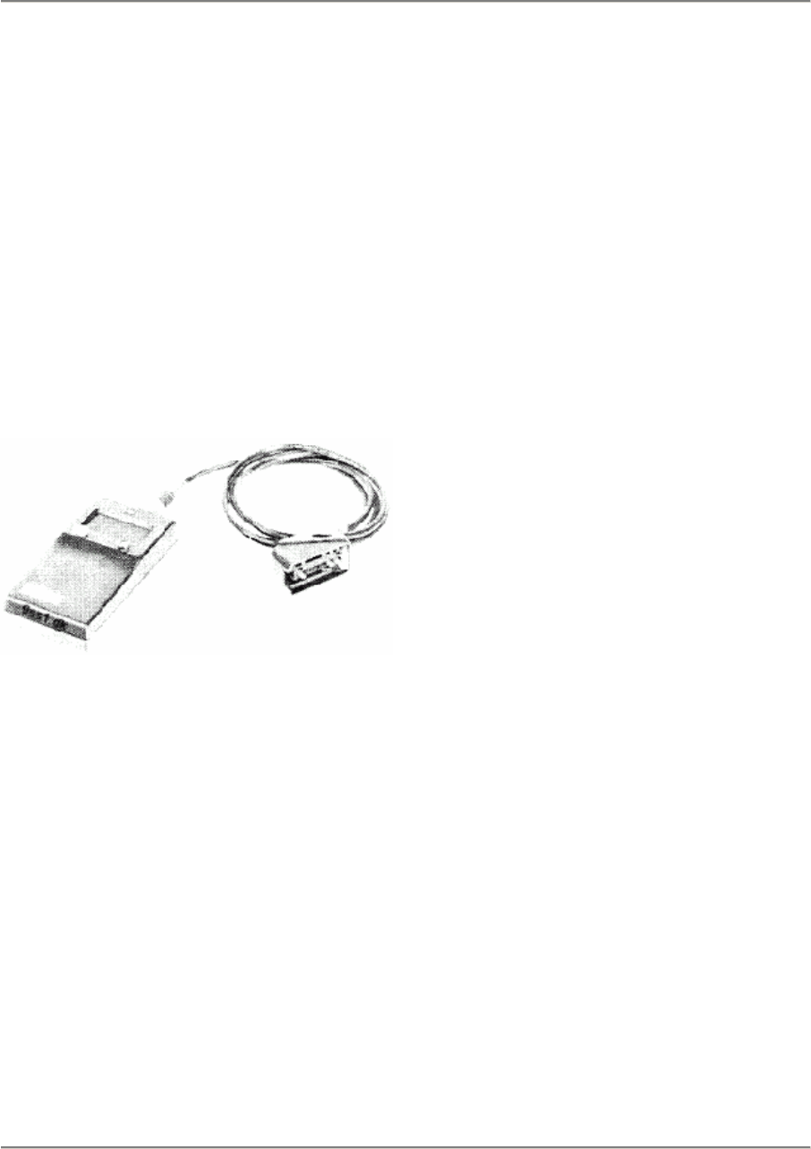
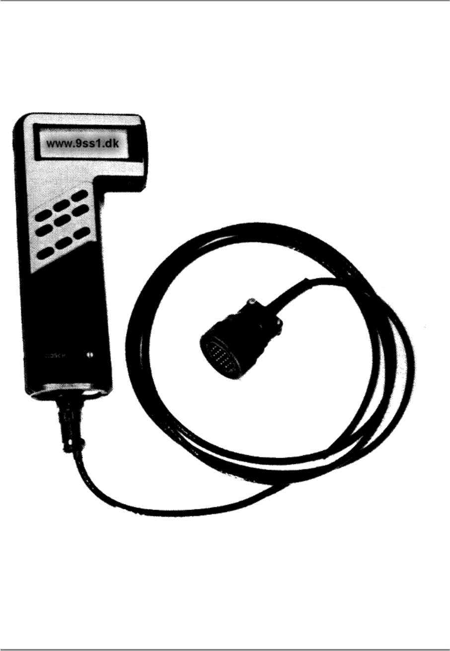
diagnostic tester (special tool No. 9268) is
then used to read out the error memory and
to test specific components and control sig-
nals af the fuel and ignition system.
87/793
Important: Before diagnosis, the battery or
the connector of the DME control unit must
not be disconnected as otherwise the error
memory will be erased.
DME control unit error diagnosis
Printed in Germany - XVI, 1987 03 - 1
03 Maintenance, Self-diagnosis 944
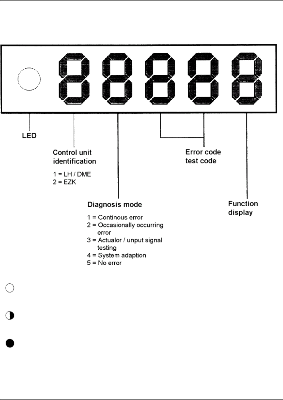
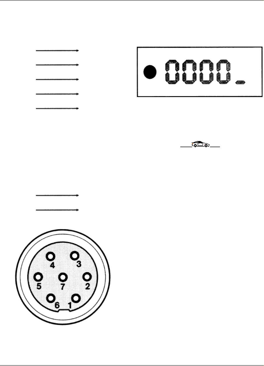
Display
LED off Test sequence terminated / igniti
Flashing LED Error code / test code
LED on Ignition on
03 - 2 DME control unit error diagnosis
Printed in Germany - XVI, 1987
944 Maintenance, Self-diagnosis 03
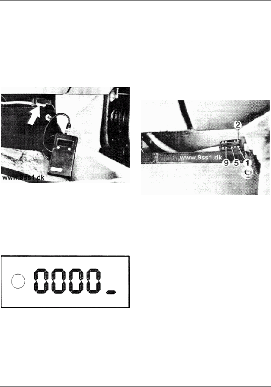
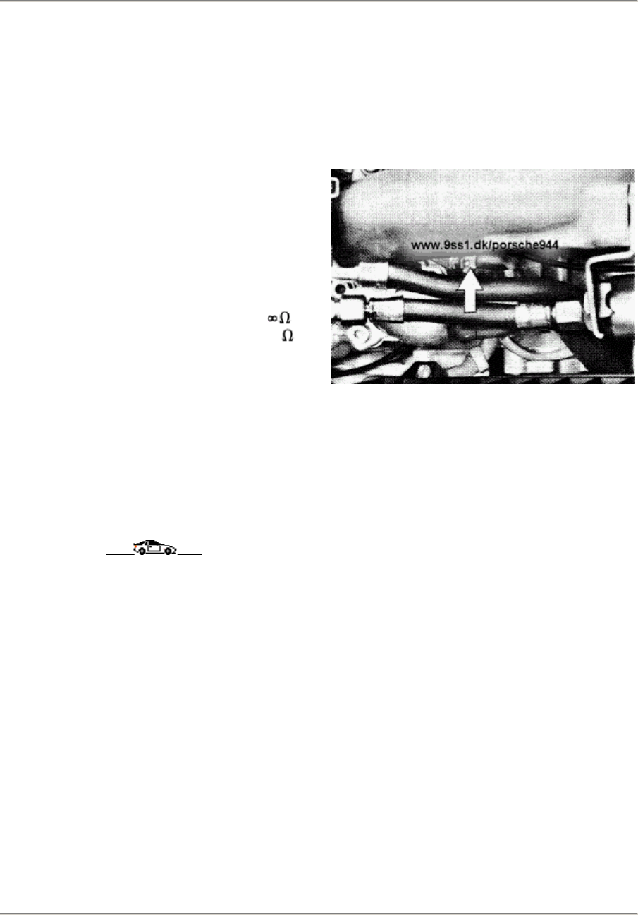
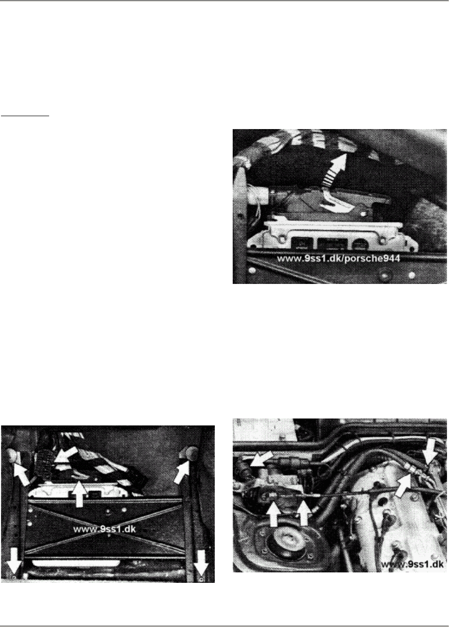
Connection in the 944 S
In the 944 S, the diagnosis socket is
attached
to a separate cable harness located above
the
DME control unit.
87/1012
Ignition off
After connecting the tester, the following dis-
play must appear.
Display:
If this is not the case, check the tester ter-
minals or check the power supply of the
diag-
nosis socket in the car by referring to the cir-
cuit diagram.
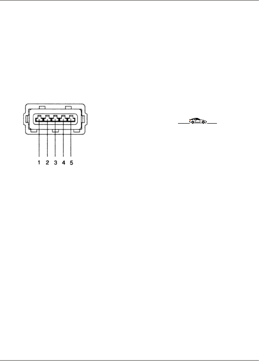
Diagnosis socket in the car
Pin 1 = terminal 15
Pin 2 = terminal 31
Pin 5 = terminal 30
Pin 9 = Hall generator
87/908
Connection in the 944 S
Printed in Germany - XVI, 1987 03 - 3
03 Maintenance, Self-diagnosis 944
Tester cable
Diagnosis
Pin 1
Pin 2
Pin 3
Pin 4
Pin 5
Pin 6
Pin 7
Pin 8
Pin 9
Pin 10
Pin 11
Pin 12
plug
unused
unused
unused
unused
unused
Round plug
Pin 4
Pin 1
Pin 7
Pin 6
Pin 2
Pin 5
Pin 3
34
Switch on the ignition
Display:
The ignition must not be switched off
during the entire error diagnosis
procedure.
03 - 4 Connection in the 944 S
Printed in Germany - XVI, 1987
944 Maintenance, Self-diagnosis 03
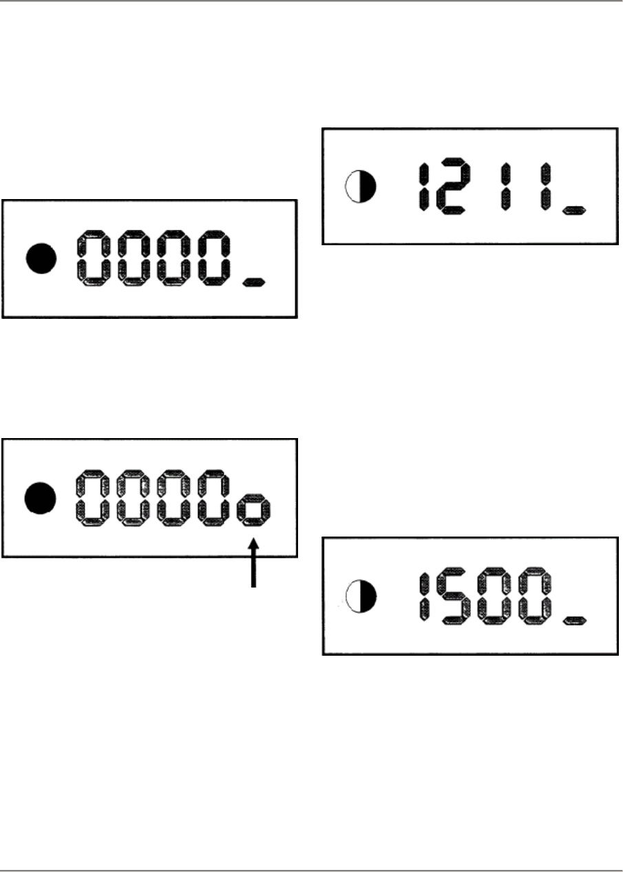
Starting error diagnosis
Condition:
Engine off
Ignition on
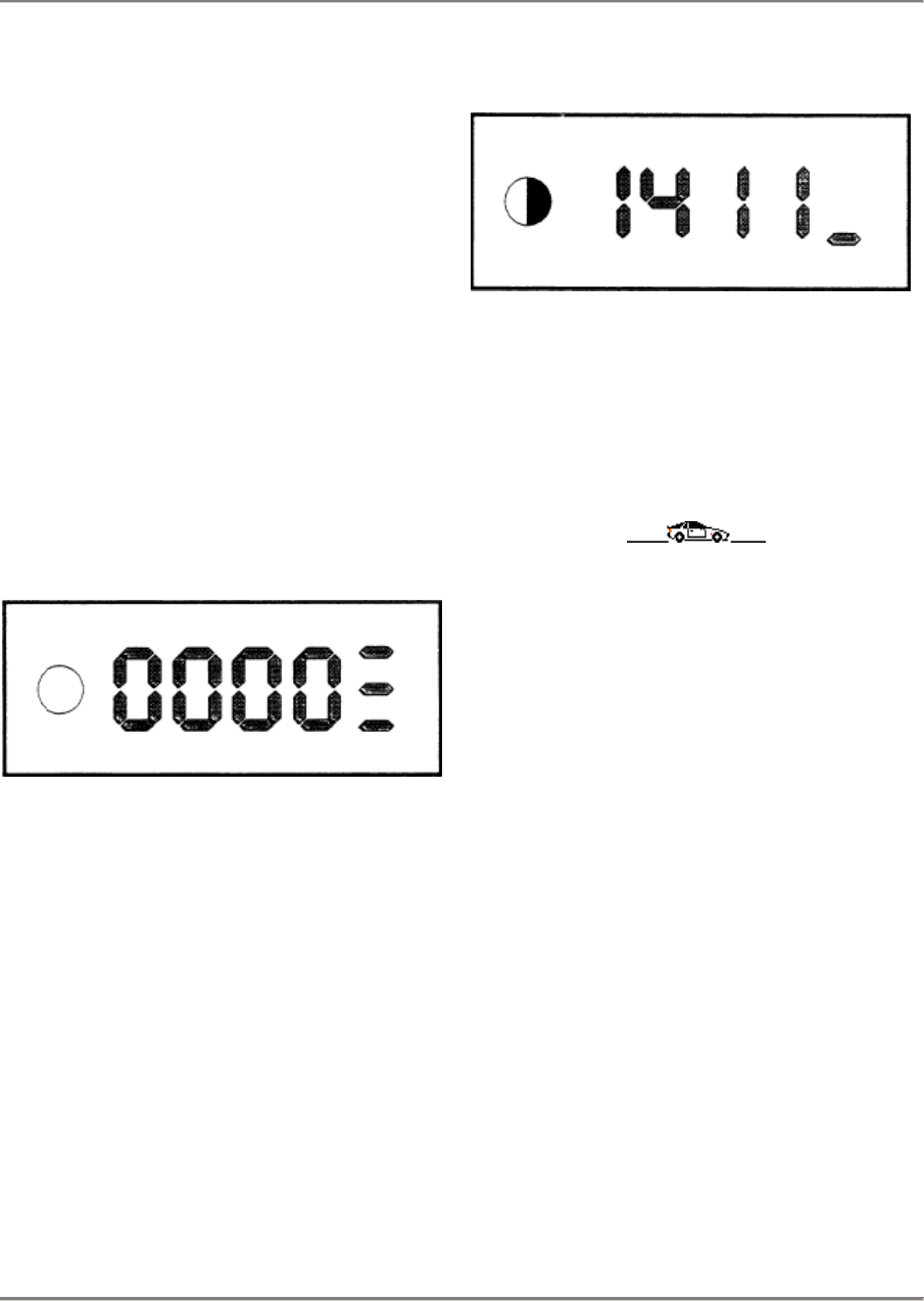
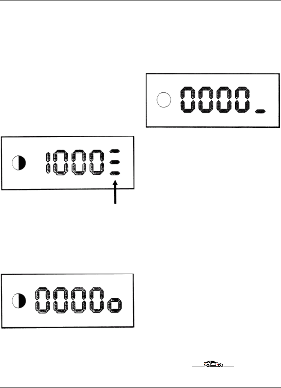
Display:
Press the green key until the clear symbol
appears on the function display.
Display:
Clear symbol
The diagnosis sequence for the DME control
unit then takes place.
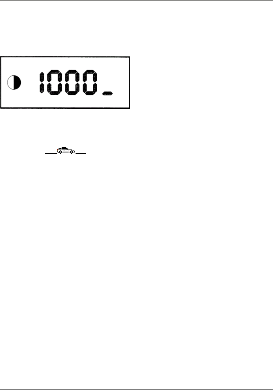
If an error is displayed - take the note of the
error (e.g. 1211).
Display:
The error is displayed until the green key is
again pressed on the tester. The next
error code is then displayed. if applicable.
This must be repeated until 1000 appears on
the display.
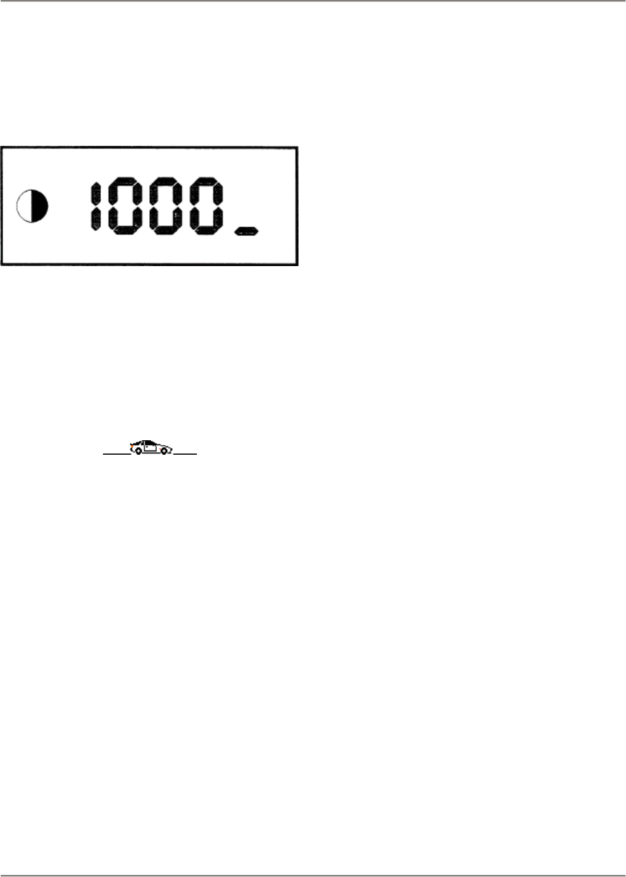
If no error has occurred. the following display
appears.
Display:
Starting error diagnosis
Printed in Germany - XVI, 1987 03 - 5
03 Maintenance, Self-diagnosis 944
Press the green key until the clear symbol ap-
pears on the function display. The following
display must then appear.
Display:
This now terminates diagnosis of the DME
control unit.
If one or several errors (up to 5) has/have
been displayed, the error memory must be
reset; see chapter (Resetting the error
memory).
03 - 6 Starting error diagnosis
Printed in Germany - XVI, 1987
944 Maintenance, Self-diagnosis 03
Actuator and input signal function
checking
An actuator and input signal function check
can be carried out independently of an error
diagnosis. This function check tests
individual
components or electrical signals with
respect
to their functioning or signal paths.
Functions
ara triggered from the diagnosis tester.
During
functional checking of components, these
must audibly or tangibly operate and can
thus
be detected as being electrically in proper
working order or defective.
An error display via the tester is not possible
in
this mode, but faulty input signals or their
wiring connection ara detected by the tester.
Starting actuator and input signal
function check
Ignition off
Press the yellow key until the function symbol
(see display) appears on the function display.
Display:
Prass the green key until the clear symbol
ap-
pears on the function display.
Display:
Switch on the ignition within 8 seconds.
Actuator and input signal function checking
Printed in Germany - XVI, 1987 03 - 7
03 Maintenance, Self-diagnosis 944
Press the green key until the ctear symbol
ap-
pears on the function display. This activates
the first testing step and the injection valves
are activated.
Display:
The injection valves must all operate audibly
or tangibly.
Note:
If later attempts are made to start the engine,
starting difficulties may occur because a
slight
residual amount of fuet is injected during this
testing step.
The testing steps remain in operation until the
green key is again pressed on the tester and
the clear symbol appears.
The next testing step is initiated by again
pressing the green key.
Refer to the test code list for the sequence
of
testing steps.
03 - 8 Actuator and input signal function checking
Printed in Germany - XVI, 1987
944 Maintenance, Self-diagnosis 03
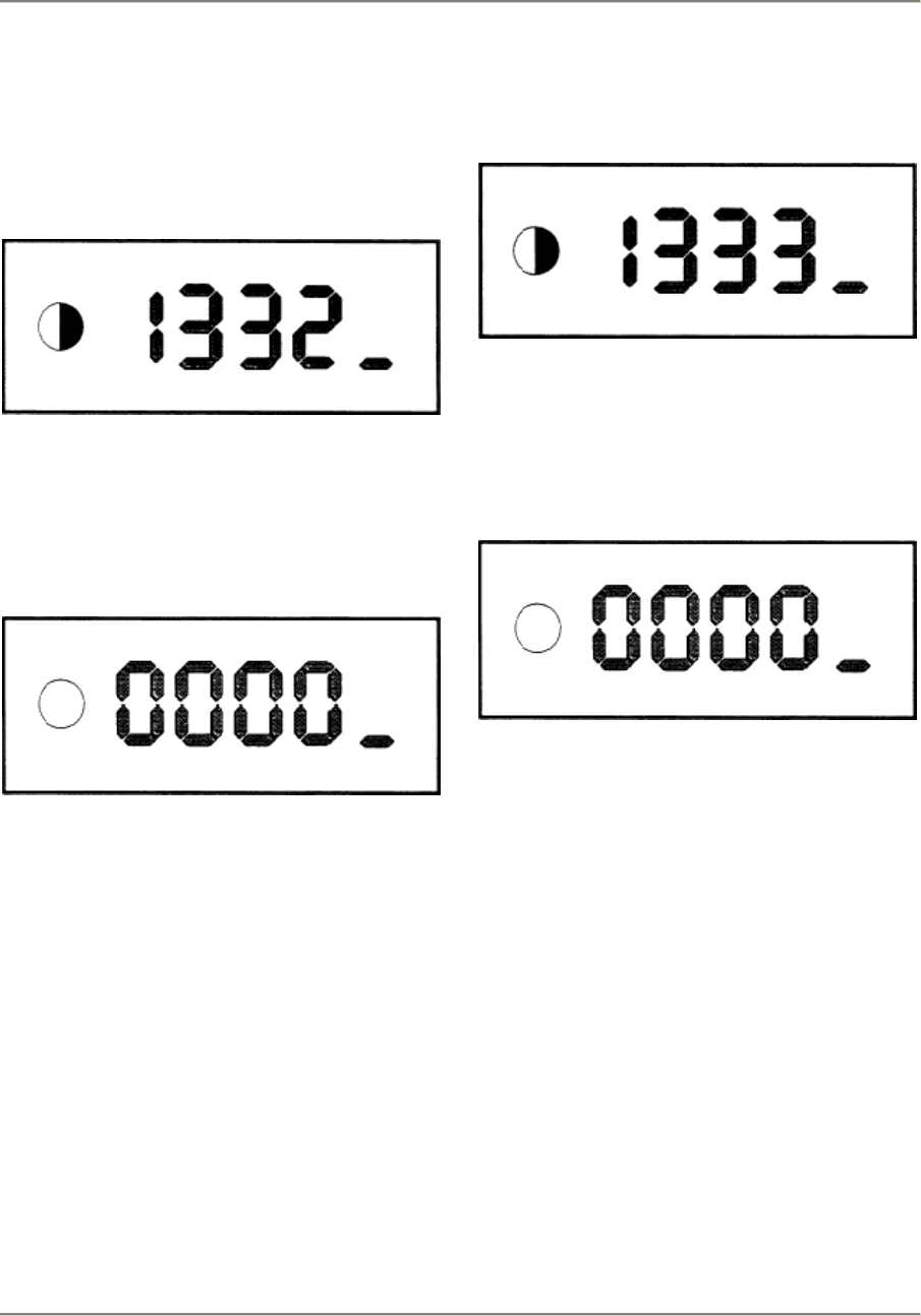
As from the "idle contact" testing step,
specific
controls must additionally be operated on the
car for the purpose of function checking.
Idle contact display:
Slightly press the accelerator. The LED must
go off after approx. 20 mm and the display
will
appear After approx. 3 s.
Display:
If this is not the case, an error has occurred
in
the area of the idle contact (see Idle contact
troubleshooting).
If the display 0000 does not appear, it is pos-
sible to switch at all times to the next testing
step. Press the green key until the clear
symbol appears.
Initiate the full load contact testing step.
Display:
Slowly press the accelerator until the full
throttle position is reached.
The LED must go off and the display will
appear after approx. 3 s.
Display:
If this is not the case, an error has occurred
in
the area of the full load contact (see Full load
contact troubleshooting).
Actuator and input signal function checking
Printed in Germany - XVI, 1987 03 - 9
03 Maintenance, Self-diagnosis 944
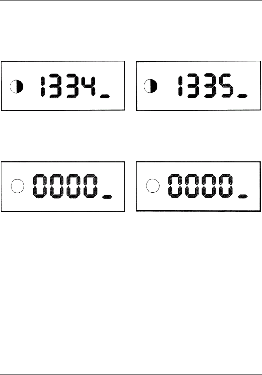
Initiale the air-conditioning control terminal
41
testing step.
Display:
Switch on the air-conditioning system.
The LED must go off and the display will
appear after approx. 3 s.
Display:
If this is not the case, an error has occurred
in
the area of the air-conditioning system's
wiring.
In the event of an error, check with reference
to the circuit diagram.
Do not switch off the air-
conditioning system.
Initiate the air-conditioning control terminal
40
testing step.
Display:
Switch off the air conditioning system.
The LED must go off and the display will
appear after approx. 3 s.
Display:
If this is not the case, an error has occurred
in
the area of the air-conditioning system's
wiring.
In the even! of an error, check with reference
to the circuit diagram.
03 - 10 Actuator and input signal function checking
Printed in Germany - XVI, 1987
944 Maintenance, Self-diagnosis 03
Press the green key until the clear symbol
appears.
Display:
End of the actuator and input signal function
checks.
Actuator and input signal function checking
Printed in Germany - XVI, 1987 03 - 11

03 944
03 - 12 Blank page

944 Maintenance, Self-diagnosis 03
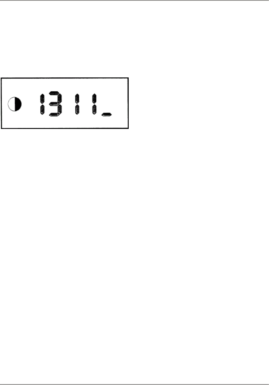
Test code list
Test code Components
1311
1321
1322
1332
1333
1334
1335
Injection valves
Rotary idle controller
Solenoid valve - tank bleeding
Idle contact
Full load contact
Air-conditioning/AC switch
Air-conditioning/compressor coupling
Test code list
Printed in Germany - XVI, 1987 03 - 13

03 944
03 - 14 Blank page
944 Maintenance, Self-diagnosis 03
System adaption
System adaption can be carried out with the
tester. That is to say. the electronic idle control
in the DME control unit is adapted to the
actual air throughput and to the current
condition of the engine.
Note:
For system adaption, it is necessary for the
engine to be at operating temperature.
Ignition off
Press the yellow key the number af times
required for the function symbol to appear
on the function display.
Display:
Press the green key until the clear symbol
appears on the function display. Start the
engine within 8 seconds. Allow the engine to
idle until the system adaption code appears.
Display:
The engine must now idle for at least 30
seconds.
System adaption is then completed.
Ignition off
System adaption
Printed in Germany - XVI, 1987 03 - 15

03 944
03 - 16 Blank Page
944 Maintenance, Self-diagnosis 03
Knock detection
Before knock detection is carried out, error
diagnosis must first of all be performed to
guarantee that no electrical error has
occurred
in the area of the knock control and the
knock
sensors.
Knock detection should not be carried out if
the customer has complained about poor
out-
put or too high a consumption, for instance.
Condition:
The engine most be at operating
temperature
during the test. Testing most be carried out
during a test drive or on the roller test stand.
Knock detection
Engine at operating temperature
While the engine is running, simultaneously
press the yellow and the green key until the
knock detection function symbol appears
on the function display.
Display:
The tester is new in knock detection mode.
Note:
Normal driving is a prerequisite for the
test drive (roller test stand).
Start the test drive (roller test stand).
Press the green key until the clear symbol
appears on the function display.
Display:
Knock detection
Printed in Germany - XVI, 1987 03 - 17
03 Maintenance, Self-diagnosis 944
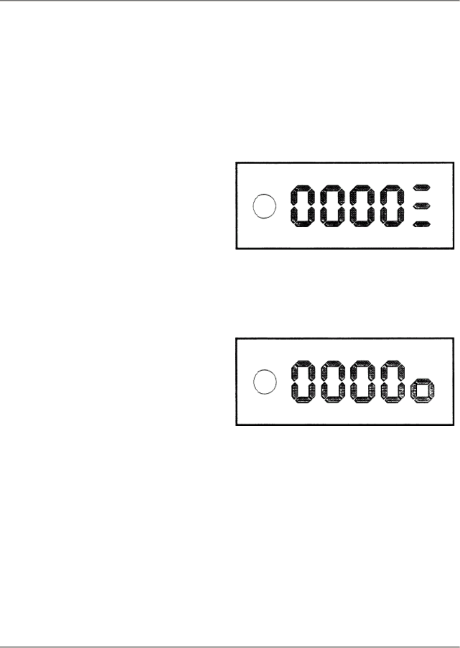
The tester is now active. If knocking occurs,
this will be indicated by the tester, e.g.:
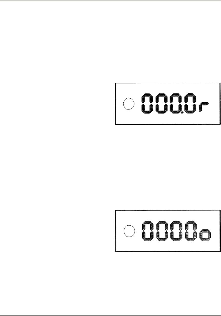
Display:
After the expiry of 10000 ignitions. the
function
display will change to "r".
Display:
Counting is now complete.
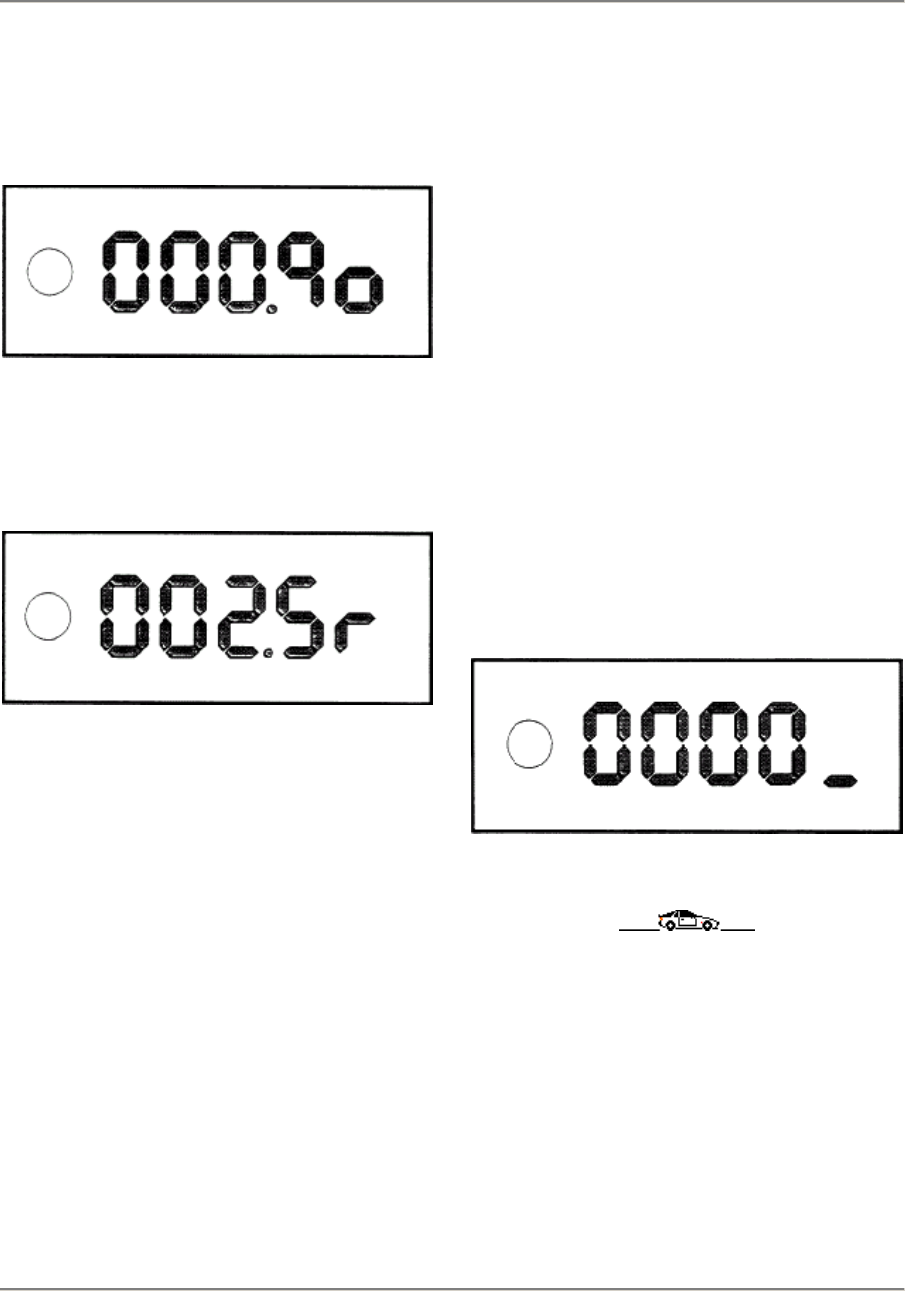
The number af knocks is displayed in per
mill.
In this example. 25 knocks have occurred.
Knock detection must be carried out until the
function display switches over from the clear
symbol to the knock detection symbol. This is
always the case once 10000 ignitions have
occurred. All occurring knocks are added up
and displayed as the end result.
To restart knack detection. the green key
must be pressed until the clear symbol again
appears.
A knock display of > 2.5 (25) draws attention
to an error.
Error possibilities:
Defective cup tappets
Conical rod damage
Crank mechanism damage
To terminale knock detection mode. the
green and yellow keys must be pressed
simultaneously until the display appears.
Display:
03 - 18 Knock detection
Printed in Germany - XVI, 1987

944 Maintenance, Self-diagnosis 03
Troubleshooting
Diagnosis using the tester can refer only to
the error path, but not to a defective
component.
Note:
Before troubleshooting, the entire error
memory must be read out.
Error code 1111
The supply voltage is too low
< 10 V or too high > 16 V.
Possible causes for too low a supply
voltage:
Battery exhausted
Poor contact on the grounding strap
Poor contact on the control unit
A defective regulator may be the cause
of
too high a supply voltage.
Troubleshooting
Printed in Germany - XVI, 1987 03 - 19
03 Maintenance, Self-diagnosis 944
Error code 1112
This error code indicates an error in the area
of the idle contact.
Possible error:
Ground fault
Switch stuck
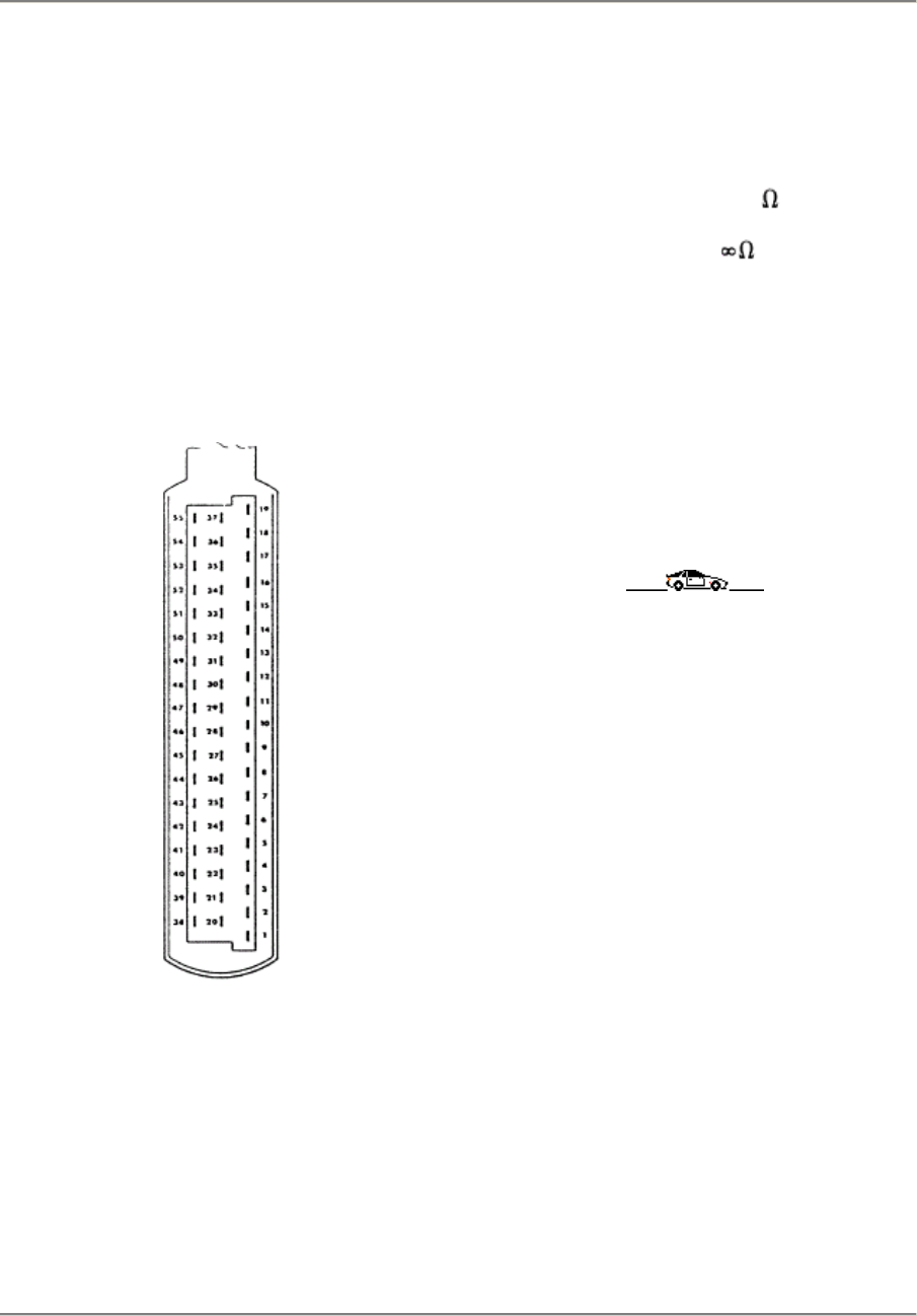
Testing the idle contact
Extract the plug from the DME control unit.
32
Connect a ohmmeter between terminal 52
and terminal 24 on the DME plug.
Display:
Throttle valve closed: R < 10
Throttle valve open: R =
Switchover must already occur if the throttle
valve is only slightly open (approx. 1°).
If the values ara not reached during this
testing
step, measurement must be repeated
directly
on the throttle valve switch.
03 - 20 Troubleshooting
Printed in Germany - XVI, 1987
944 Maintenance, Self-diagnosis 03
Error code 1113
This error code draws attention to an error in
the area of the full load contact.
Possible errors:
Ground fault
Switch stuck
Testing the full load contact
Connect an ohmmeter between terminal 53
and terminal 24 on the DME plug.
Display:
Throttle valve closed: R =
Throttle valve in full load position: R < 10
The switching point must be briefly before
full
load.
If the values are not reached in this testing
step, measurement must be repeated
directly
on the throttle valve switch.
Error code 1114
This error code draws attention to an error in
the area of the engine temperature sensor
(NTC 2).
87/912
Possible errors
Ground fault
Short to positive
Wire discontinuity
NTC 2 defective
Testing the engine temperature sensor.
Connect an ohmmeter between terminal 45
and terminal 24 on the DME plug.
Troubleshooting
Printed in Germany - XVI, 1987 03 - 21
03 Maintenance, Self-diagnosis 944
Display
0°C =
15 - 30°C =
80°C =
100°C =
4400 -
1400 -
250 -
160 -
6800
3600
390
21
If the values are not reached in this testing
step, measurement must be carried out
directly on the engine temperature sensor.
The engine temperature sensor (NTC 2) in-
forms the control unit about the current
engine
temperature. It results in mixture enrichment
during cold starts or hot running.
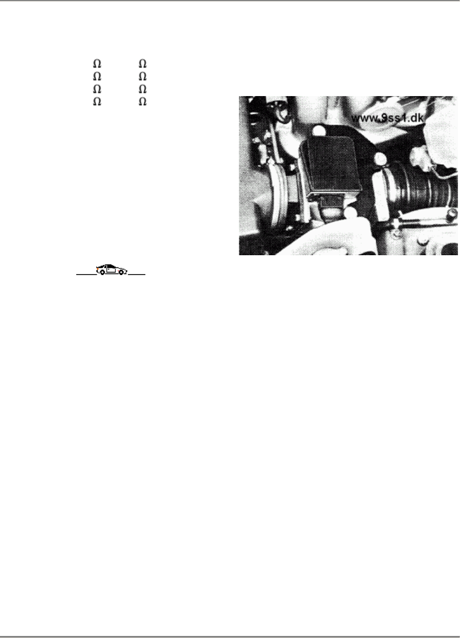
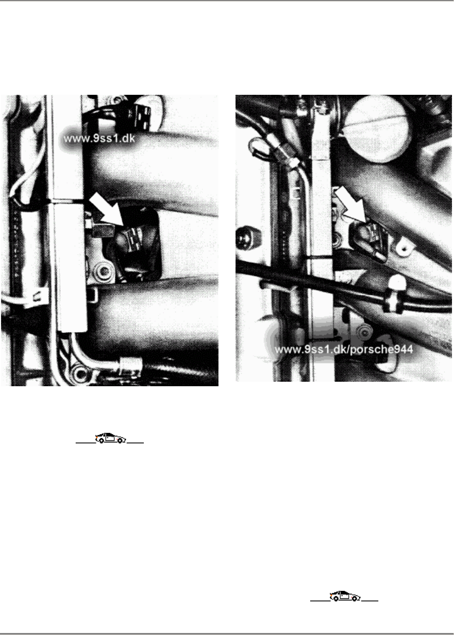
Error code 1121
This error code draws attention to an error in
the area of the air-flow sensor.
87/907
Possible errors:
Ground fault
Short to positive
Wire discontinuity
During this test, the plug af the DME
control unit must be plugged in.
03 - 22 Troubleshooting
Printed in Germany - XVI, 1987
944 Maintenance, Self-diagnosis 03
Testing the power supply of the air-flow
sensor:
Ignition on
On the extracted plug of the air-flow sensor, a
voltage of 5 V +- 0,5 V must be measurable
between terminal 3 (positive) and terminal 4
(negative) (if necessary, check by reference
to the circuit diagram).
33
Testing the air-flow sensor
From the extracted plug of the air-flow
sensor,
link plug terminal 3 to air-flow sensor plug ter-
minal 3 and plug terminal 4 to air-flow sensor
plug terminal 4 using an auxiliary cable.
Measure the voltage between terminal 2 of
the air-flow sensor and ground.
Display:
approx. 250 - 260 mV
Detach the top of the air filter.
Using a non-metallic tool, slowly force the
airflow sensor valve to full load position.
A voltage rise must be observed during this
time.
Display:
approx. 0.2 V - ca. 4.6 V
No abrupt voltage changes must be
observed
during opening or closing. (Abrupt voltage
changes. i.e. the air-flow sensor is
defective).
Troubleshooting
Printed in Germany - XVI, 1987 03 - 23
03 Maintenance, Self-diagnosis 944
Error code 1123
When this error code appears, the Lambda
control has detected too rich ar too lean
a mixture.
Possible causes for too lean a mixture:
Lambda probe ground fault
Intiltrated air on the intake side
Intiltrated air on the exhaust side of the
Lambda probe
Injection valve does not open
Ignition cut-out
Fuel pressure too low
Possible causes for too rich a mixture:
No partial vaccum on the pressure
regulator
Injection valve does not close
Return to the fuet tank clogged.
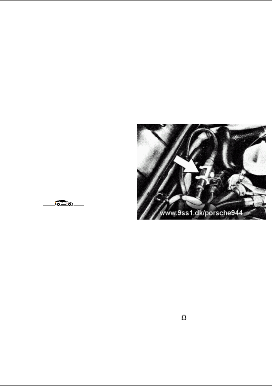
Error code 1124
This error code draws attention to an error
in the area of the Lambda probe.
Possible errors:
Ground fault
Short to positive
Wire discontinuity
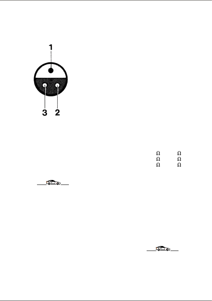
Testing the Lambda probe signal.
Figure 87/906
Disconnect the Lambda probe plug.
Note:
The voltage af the Lambda probe must
only
be measured using a digital voltmeter, or
only using a comparable measuring instru-
ment with an internal resistanee (Ri) of no
less than 10 M .
03 - 24 Troubleshooting
Printed in Germany - XVI, 1987
944 Maintenance, Self-diagnosis 03
Measure the voltage between pin 1 and
engine
ground.
35
The voltage is within the range of approx. 150
mV - 900 mV depending on the mixture
composition.
Check the cable harness to the DME control
unit with reference to the circuit diagram.
Error code 1125
This error code indicates an error in the
area
of the intake air temperature sensor (NTC
1)
in the air-flow sensor.
Possible errors:
Ground fault
Short to positive
Wire discontinuity
NTC 1 defective
Testing the intake air temperature
sensor.
Connect an ohmmeter between terminal 44
and terminal 26 on the DME plug.
Display:
0°C =
15 - 30°C =
40°C =
4400 -
1400 -
1000 -
6800
3600
1300
If the values are not reached during this
testing step, measurement must be carried
out directly on the intake air tempertaure
sensor.
Connect an ohmmeter between pin 1 and
pin 4 on the air-flow sensor.
Display: as above
Troubleshooting
Printed in Germany - XVI, 1987 03 - 25
03 Maintenance, Self-diagnosis 944
Error code 1131
This error code draws attention to an error in
the area of knock sensor 1.
87/911
Error code 1132
This error code draws attention to an error in
the area of knock sensor 2.
87/910
Error testing of the knock sensors is an
active
error test, i.e. error testing is carried out
during
driving.
If an error has occurred, first check the
wiring
for a ground fault, a short to positive and for
continuity with reference to the circuit
diagram
before replacing the knock sensor.
03 - 26 Troubleshooting
Printed in Germany - XVI, 1987
944 Maintenance, Self-diagnosis 03
Error code 1133
Error code 1133 draws attention to an
error in
the area of the knock control in the DME
con-
trol unit. If this error code appears, the
DME
control unit must be replaced.
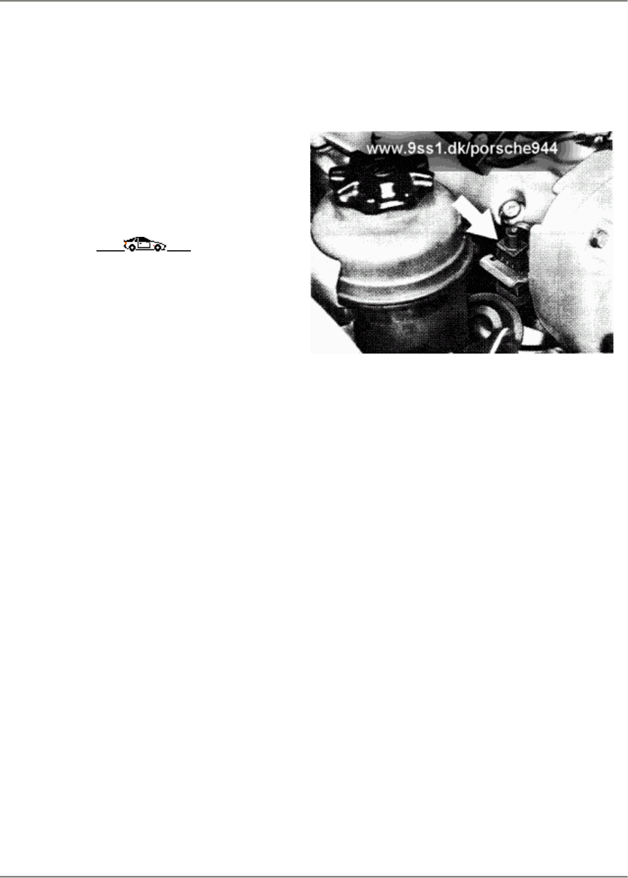
Error code 1134
This error code draws attention to an error in
the area of the Hall generator.
87/904
Possible errors:
Ground fault
Short to positive
Wire discontinuity
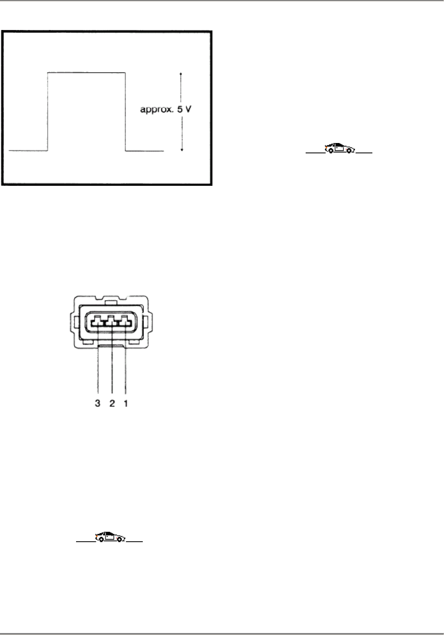
Testing the Hall generator signal
Using a suitable auxiliary æble, connect an os-
cilloscope to the diagnosis plug, pin 9 (square-
wave signal) and pin 2 (ground). If the Hall
gen-
erator signal is O.K., the following picture must
appear on the oscilloscope's screen.
Troubleshooting
Printed in Germany - XVI, 1987 03 - 27
03 Maintenance, Self-diagnosis 944
Testing the Hall generator's power supply
Disconnect the Hall generator's connector.
Ignition on
36
A voltage of 12 Volt +- 1 V must be
measurable between pin 1 (positive) and pin
3
(negative). If this is not the case, check the
wiring with reference to the circuit diagram.
Error code 1141
Error code 1141 draws attention to an error
in
the area of the DME control unit. If this error
code appears, the DME control unit must be
replaced.
03 - 28 Troubleshooting
Printed in Germany - XVI, 1987

944 Maintenance, Self-diagnosis 03
Error code - List
Error code
1500
1000
1111
1112
1113
1114
1121
1123
1124
1125
1131
1132
1133
1134
1141
Error path
No error
Output end
Supply voltage too low/high
Idle contact
Full load contact
NTC 2
Air-flow sensor
Lambda control detects a too rich / too lean mixture
Lambda probe signal not correct
NTC 1
Knock sensor 1
Knock sensor 2
Knock control in the control unit
Hall generator signal
DME control unit
A digit 2 (e.g. 1211) may appear in the second error code digit position to indicate "sporadic
errors", i.e. an occasionally occurring error.
This does not apply to error codes 1000 and 1500.
Error code - List
Printed in Germany - XVI, 1987 03 - 29

03 944
03 - 30 Blank page
944 Maintenance, Self-diagnosis 03
Resetting the error memory
Once the DME control unit error diagnosis
has been completed. this is completed by
error code 1000. The error memory cannot
be reset as follows until this error code
appears:
The yellow key must be pressed until the
function symbol (see display) appears on
the function display.
Display:
Function symbol
The green key must be pressed until the
clear
symbol appears on the function display.
Display:
The error memory is reset if the LED goes
off
and the function display changes to 0000.
Display:
Note:
A test drive must be carried out after
resetting
the error memory.
At the same time, pay attention to the
following:
1.
The engine must be at operating
tempera-
ture. i.e. at least 80°C.
2. The duration ot the test drive (minimum 6
minutes).
3. At the end ot the test drive. run the
engine
for at least 60 seconds without opening
the
throttle valve.
After the test drive, read out the error
memory
once again.
Resetting the error memory
Printed in Germany - XVI, 1987 03 - 31

03 Self-diagnosis 944
Operating conditions for start of diagnosis
Systems Ignition on
Engine standing still
Engine running
944 S / 944 S2
DME
Airbag
Alarm system
yes
yes
yes
to n < 2000 rpm
yes
yes
Webdesign from www.9ss1.dk/porsche944
03 - 32 Operating conditions for start of diagnosis
Printed in Germany - XXIV, 1991
944 Self-diagnosis 03
Operating instructions for System Tester 9288
Operating instructions for System Tester 9288
Printed in Germany - XXIV, 1991 03 - 33
03 Self-diagnosis 944
1. General information
1.1 Application
The Systemtester 9288 (BOSCH KTS 301) is a microprocessor-con-
trolled self-diagnosis tester.
All systems which have a diagnosis interface as per ISO Standard can
be tested with this tester. The following tests are possible:
* Reading out the fault memory
* Testing of the actuators
* Testing the circuit inputs
* System adaptation
* Engine-knock detection
* Sensor and status checks, tire-pressure monitoring (RDK)
The Systemtester 9288 is a high-quality pjece of electronic equip-
ment In order to prevent damage to the equipment as a result of
improper use, please read the information in the operating
instructions carefully and comply with it.
In addition. the instructions (specifications) of the vehicle manufac
turer are also to be observed.
If the tester should fail, check the following points before sending it
in for repair:
1. Has the tester been operated incorrectly?
2. Is the battery sufficiently charged?
3. Is the adapter cable OK?
(Please note when checking the adapter cable that a highly sensi-
tive electronic matching circuit is installed in the vicinity of the 19-
pore plug).
1.2 Construction (Fig. 1)
No.
Description Function Remarks
1 LCD indicator Dot matrix 5 x 8
4 lines each with 20 characters
Foreign languages possible
Illumination
If the Systemtester 9288 is switched on
without the program module, following
the self-test the tester switches off auto-
matically and informs the user that the
program module is not fitted.
2 Keyboard Keys 1, 2, 3
=
Selection key
Keys < > =
Previous peget next page
Key H =
Help menu, e.g.:
Illumination
Screens stored
Control-unit overview
Setting up printer
Switching off unit
Key N =
Return to the next higher
program level following
termination of a test
sequence or, during a test
sequence, return to the
last display
Key =
Storing indication
Key =
Playing back
stored reading
Switching on
=
Press any key
Switching off
(automatic) =
180 s after last
depression of a key or
if no data stream flows
across the seriel
interface.
The last fjeld in the top right-hand corner is
filled completely, this means that this is a
stored figure and not an actual,
real-life figure.
Fitted accumulator with NiCd batteries.
The Systemtester 9288 must be switched off
during the initial battery charging process.
Charging time > 8 hours
Discharged upon delivery. Following charge:
Operating time:
4 - 8 hours without scale illumination
1 - 2 hours with scale illumination
Connection to vehicle battery by means
of vehicle-specific adapter lead (see 1.4) Connection through ISO-interface
Charging voltage supply
3 Power supply
If the voltage is not sufficient,
"Charge battery" appears
on the display. If this is
not done, the unit switches
itself off. Battery charger (accessory) For test operation and for charging
the NiCd batteries.
4 Connection for
Input and output devices Connection facility for Printer
e. g. Epson, IBM. Hewlett Packard (HP) The Systemtester 92BB transmits data with
the following configurations:
8 data bits / 1 start bit / 1 stop bit /
No parity (for printer matching)
5 Connection for vehicle
specific adapter lead Reading out the data Input for flashing-code support
6 Plus-in programme module
(see also Figure 2)
C-MOS !
Do not touch plug !
Operating system
LCD drive
Keyboard
Interface communication
Computations and data conversions
Plug in module:
remove rubber protector,
insert modul e fully.
03 - 34 Operating instructions for System Tester 9288
Printed in Germany - XXIV, 1991

944 Self-diagnosis 03
1.3 Battery charger run off mains voltage (Figure 3)
- Accessory -
Item 1 Charger with connecting cable, 1.5 m long
Item 2 8-pin AMP plug
1.4 Vehicle-specific adapter cable
Porsche No. 000 721 928.81
1.5 Connecting lead (Figure 4)
- Self-fabrication -
for printer, programme load station or similar unit.
For interface-trunk assignment, see manual of corresponding unit.
Printer cable for standard D 25
BOSCH No. 1 684 465 193
Printer cable for EPSON
BOSCH No. 1 684 465 194
2. Connection
The following points must be observed:
- No gear must be engaged on the vehicle (Automatic transmission
in position N - P) - Danger of Accident!
- ALL work on the vehicle must only be carried outwith the ignition
switched off.
After having connected the vehicle-specific adapter cable, the in-
structions listed under "3" ara displayed on the Systemtester 9288:
2.1 Charging with the battery charger (Fig. 3)
Connecting the Systemtester 9288 to the battery charger.
(Fig.1, pos.5).
2.2 Diagnosis
Connecting the Systemtester 9288 to the diagnosis plug in the
vehicle by means of the vehicle-specific adapter cable.
Switch on the tester and proceed according to the instruetions
displayed.
3. Testing
Scope of module:
Guidance through the menu, communication with the ECU, reading
out the error memory and selection of the "Help" menus, actuator
diagnosis, circuit inputs and system adaptation, engine-knock detec-
tion, sensor and event check for the tire-pressure monitor (RDK).
3.1
Reading-out the error memory
Connect the Systemtester 9288 (see 2.)
Switch on the Systemtester,
(possible with every key!)
Display:
PORSCHE
Eprom modul
Mod. intro.
xx.xx.xx
eng
If a specific instruction does not appear in a display, it is always
possible to proceed by pressing the button >.
Due to the fact that the Systemtester 9288 can store error displays
(see Chapter 3.7), the following display will appear if errors have
been stored in the image memory:
Stored displays
erased ?
1 = yes
3 = no
Key 3
Display:
Print out
displays:
continue:
H
>
H = Help menu (see 3.6) or key 1
Display:
Vehicle types
1 = 944 S
2 = 911 Carrera 4
3 = 928 S 4
Selection of the vehicle type with key 1, 2 or 3.
After the vehicle type has been selected, the following
instruction appears:
Connect adapter
cable to veh. plug.
Ignition "ON".
After completion:
>
The following then appears:
Wait for
Data
Break off test:
N
After a short pause. the Systemtester 9288 reperts all the sys-
tems that are installed in the particular vehicle. If a system is pre-
ceded by " # ", this means that at least 1 error is stored in that
particular system.
Examples:
Installed systems
1 = # LH
2 = # EZK
3 = RDK
The particular system can be selected by means ef key 1, 2 or 3.
After selection (for instance with key 1), the following display
appears:
LH
System:
Ser. No.:
RB. No.:
L01 LH-JET
92861812313
0280002507
Operating instructions for System Tester 9288
Printed in Germany - XXIV, 1991 03 - 35
03 Self-diagnosis 944
After pressing the key > , a selection menu is displayed:
Menu
1 = Fault memory
2 = Drive links
3 = Input signals
>
< Menu
1 = System adaptation
In the example - press key 1. There then follows the display of
the number of errors which are stored (if any).
Number of
faults
- 2 -
Proceed with key >
Additional info to
every display with
key 1
continue:
>
Proceed with key >
Error output:
1: Engine
temperature sensor 2
Short to ground
not present
If key 1 is pressed instead of the > key, the corresponding error
code display appears (the last two digits of the flashing code).
Fault code: - 14 -
Proceed with key >
Further errors are displayed (if they exist):
2 : Idle contact
Short to ground
present
If key 1 is pressed instead of key > the corresponding error-code
display appears (the last two digits of the flashing code).
Fault code: - 12 -
After the last displayed error, the following instruction appears:
Repair fault accord-
ing to repair
instructions
Continue:
>
Proceed with key >
Fault repaired ?
1 = yes
3 = no
Return to display "No. of errors" with key 3.
Proceed with key 1:
Fault memory
1 = Erase
3 = Do not erase
If key 3 is pressed:
= Return to menu "error memory".
The error memory is not erased!
Proceed with key 1:
Fault memory
has been cleared
Return:
N
The test scope "Read-out error memory" is terminated
at this point.
3.2 Actuator diagnosis
If an actuator is selecled, this is triggered by the ECU so that it can
be checked for correct functioning.
The various actuators components are gone through one after
the other and are selected with the > key.
Operate the Systemtester 9288 as described under 3.1 until
the following menu display appears:
Menu
1 = Fault memory
2 = Drive links
3 = Input signals
>
After pressing key 2, the display for the first actuator appears:
Injector
to activate
1 = Start
Continue:
>
If key > is pressed, the next actuator is selected.
Pressing key 1 results in the following instruction:
Can injectors be
heard / felt?
1 = yes
3 = no
03 - 36 Operating instructions for System Tester 9288
Printed in Germany - XXIV, 1991
944 Self-diagnosis 03
Key 1 selects the next actuator (e. g. idle actuator). Following
instruction:
Repair fault accord-
ing to repair
instructions
Continue:
>
After pressing key > , the following display appears:
Injector
to activate
1 = Start
Continue:
>
Proceed with key 1
Can injectors be
heard / felt?
1 = yes
3 = no
Proceed with key 1 to the next actuator.
Idle stabilizer
to activate
1 = Start
Continue:
>
Proceed with key 1
Can idle stabilizer
be heard / felt?
1 = yes
3 = no
By pressing key 1, the next actuator is selected. After pressing
key 3, the next instruction appears:
Repair fault accord-
ing to repair
instructions
Continue:
>
Proceed with key >
Idle stabilizer
to activate
1 = Start
Continue:
>
After pressing key 1. the following display appears:
Can idle stabilizer
be heard / felt?
1 = yes
3 = no
By pressing key 1. the next actuator is selected. The actuators are
selected one after the other and triggered until the following
display appears:
Drive link test
completed
Return:
N
By pressing the key N. the operator is returned to the menu.
3.3 Circuit inputs
In addition lo the actuators, the Systemtester 9288 can also
check circuit inputs. To this end, operate the Systemtester 9288
in accordance with 3.1 until this menu display appears:
Menu
1 = Fault memory
2 = Drive links
3 = Input signals
>
Press key 3
Idle contact
1 = Start
Continue:
>
By pressing key > the next circuit input is selected.
The next display appears when key 1 is pressed.
Activate accl. pedal
Idle contact
- closed -
Continue:
>
Operate the accelerator pedal, the following display appears:
Activate accl. pedal
Idle contact
- open -
Continue:
>
The next circuit input is selected by pressing key >. Repeat until
this display appears:
Input signals
testing compleled
Return:
N
Press key N for return to menu
3.4 System adaptation
When the function "System adaplation" is triggered. the ECU re-
gisters the basic air requirement of the engine.
To this end. operate the Systemtester 9288 as per 3.1 until the
following menu display appears:
Menu
1 = Fault memory
2 = Drive links
3 = Input signals
>
Proceed with key >
< Menu
1 = System adaptation
Operating instructions for System Tester 9288
Printed in Germany - XXIV, 1991 03 - 37
03 Self-diagnosis 944
Proceed with key 1
Prerequisite:
Eng. at oper. temp.
with all consumers
and ignition off.
Proceed with key >
System adaptation
1 = Start
Return:
N
If key N is pressed
= return to menu.
If key 1 is pressed:
Start engine !
Following engine start there appears:
System is being
adapted
Please wait !
Atter approx. 30 secs there appears:
System adaptation
completed
Return:
N
If it is impossible to carry out system adaptation (idle contact not
closed, or delective). the following display appears:
No system adapta-
tion possible
Idle contact ?
Return:
N
Atter cornpletion of the system adaptation, return to the menu
with key N.
3.5 Engine-knock registration
The engine-knock registration function can only be triggered
through the EZK or DME control unit.
To this end, operate the Systemtester 9288 as described in 3.1
until the following display appears:
Installed systems
1 = # LH
2 = # EZK
3 = RDK
The particular system can be selected by means of key 1, 2 or 3.
For instance with key 2 the folIowing display appears:
EZK
System: E01EZK
Ser. No.: 92861812415
RB. No.: 0227400154
Proceed with key >
The following menu display appears:
< Menu
1 = Fault memory
2 = Knock registration
Proceed with key 2
Condition:
Engine at operating
temperature
>
Proceed with key >
< Start knock
registration before
test drive
>
Proceed with key >
< A normal test
drive is a pre-
requisite
>
Proceed with key >
< Stop the test
drive only if the
display with the no.
of knocks comes on.
Proeeed with key >
Knock registration
1 = Start
Return:
N
Pressing key 1 activates the engine-knock counter:
Knoek registration
in progress
Please wait !
03 - 38 Operating instructions for System Tester 9288
Printed in Germany - XXIV, 1991
944 Self-diagnosis 03
The knock counter registers 10,000 ignitions before the display
with the actual number of combustion "knocks" appears.
Number
Knocks:
Combustion:
Continue:
xxx
xxxxx
>
Proceed with key >
Knock registration
completed
Return:
N
If knock registration is impossible (due to lack of engine-speed
signal), the following display appears:
No knock regist-
ration possible.
RPM signal?
Return:
N
Following completion of the knock registration test, return to the
menu with key N.
3.6 Help menu
The "Help" menu can be selected from every display by pressing
key H. Return to the initial display with key N.
Help menu
1 = Illumination
2 = Display stored
3 = Ctrl. unit chart
>
Proceed, for instance with key 1:
Key 1:
The scale illumination is switched on and the tester returns to the
previous display.
Or with key 2:
Data display stored
1 = Print
2 = Clear
Proceed with key 1
Stored displays ara printed out (If printer connected).
Proceed with key 2
Stored displays are erased.
With the "Help" menu, for instance
Help menu
1 = Illumination
2 = Display stored
3 = Crtl. unit chart
>
If the key > is pressed, a further section of the "Help" menu is
displayed:
< Help menu
1 = Printer setting
2 = Switch of! equip.
3 = Baud Rate
Proceed for instance with key 1
Printer setting
1 = IBM
2 = HP Quiet Jet
3 = EPSON
The selection of the printer results in the tester being set up for
the printer type in question.
3.7 Store measurement displays (Key )
Using key , all displays can be stored manually.
The following displays are stored automatically:
- ECU-Identity
- Installed systems
- All existing errors
When the memory limit is reached, the following instruction
is displayed:
Data display mem.
full !
Return:
N
3.8 Show stored measurement displays (Key )
Using the keys < or >, the stored displays for the selected
system can be shown.
The stored displays can be called up by means of the key.
The system selection (LH - EZK - RDK) takes place with the keys
1, 2 or 3.
4. Service and wear parts (BOSCH)
Fig. BOSCH Part No. Designation Comment
1/3
4/1
4/2
4/3
1 687 335 002
1 684 483 152
1 684 485 170
1 680 552 005
1 684 465 193
1 684 465 194
NC- battery
Plug
Socket
Screwed cap
Printer cable
(Standard D25)
Printer cable
(EPSON)
9 pole
4.1 Service parts (Porsche)
Designation Porsche Part No. Special tool No.
Systemtester 9288
Adapter cable
Battery charger
Module (D)
Module (GB/USA)
Module (F)
Module (I)
Module (E)
000.721.928.80
000.721.928.81
000.721.928.82
000.721.928.84
000.721.928.85
000.721.928.86
000.721.928.87
000.721.928.88
9288
9288/1
9288/2
9288/4
9288/5
9288/6
9288/7
9288/8
Operating instructions for System Tester 9288
Printed in Germany - XXIV, 1991 03 - 39

10 944
10 - 0100 Blank page

944 Engine, Crankcase 10
Tightening torques for engine (16-valve)
Location Thread Tightening torque Nm (ftlb)
Crankshaft/
crankcase
Upper and lower
crankcase sections
(studs)
Knock sensor
Cylinder head
Cylinder head to upper
crankcase section
Engine type M 44.40
Engine type M 44.41
(3.0 l)
Camshaft bearing to
cylinder head
Allen screws for chain
tensioner
Banjo bolt /
Chain tensioner
Cover for cylinder head
Fastening /
Hall sensor
M 12 x 1.5
M 10
M 8
M 6
M 8
M 12
M 12
M 8
M 6
M 8 x 1
M 6
M 6
30(22)
60 ° torque angle
20(15)
50(37)
1 st stage
2nd stage
1 st stage
2nd stage
20(15)
10(7.5)
20(15) original screw
without washer
refer to Page 15 - 110
20(15)
90 ° torque angle
90 ° torque angle
20(15)
60 ° torque angle
90 ° torque angle
1 st stage
2nd stage
3nd stage
1 st stage
2nd stage
3nd stage
20(15)
10(7.5)
10(7.5)
10(7.5)
10(7.5)
Tightening torques for engine (16-valve)
Printed in Germany - XIX, 1989 01 - 0101

10 Engine, Crankcase 944
Tolerances and wear limits
Engine M 44.40/41
Cooling system
Coolant thermostat
Cooling system cap
Pressure valve
Vacuum valve
Oil circuit
Oil consumption
Oil pressure
at 80° C oil temperature:
at 5,000 rpm
Oil capacity
Difference of quantity between
dipstick marks
Valve timing
Camshaft bore
Camshaft
Camshaft
Bucket tappet bore
Bucket tappets
Camshaft
Opening temperature
opens at excess pressure
opens at vacuum
l/600 miles
excess pressure
6 l, from MY '88
Inner dia.
Dia.
Axial clearance
Inner dia.
dia.
Runout
For installing
(new) Wear
limit
81-85° C
1.3...1.5
0.1 bar
approx. 1.5
approx. 4 bar
6.5 l
approx. 1.5 l
28 + 0.021
- 0
28 - 0.04
- 0.055
0.08...0.18
35 - 0.025
- 0.041
35 - 0.025
- 0.041
0.02
10 - 0102 Tolerances and wear limits
Printed in Germany - XXIV, 1991

944 Engine, Crankcase 10
Tolerances and wear limits
Engine M 44.40/41
Cylinder head with valves
Mating surface
Valve seat width
Exhaust
Seating angle
Outer correction angle
Inner correction angle
Valve guides:
Valve stem:
Intake
Exhaust
Valve guide/valve stem
Intake
Exhaust
Compression
Pistons with connecting rods
Cylinders/pistons
Piston rings M 44/40
Piston rings M 44/41
Piston rings M 44/40
Piston rings M 44/41
Distortion
Intake:
Inner dia.
Dia.
Dia.
Rocking clearance
Clearance
Height clearance
Height clearance
Groove 1
Groove 2
Groove 3
Groove 1
Groove 2
Groove 3
Ring gap clearance
Ring gap clearance
Groove 1
Groove 2
Groove 3
Groove 1
Groove 2
Groove 3
For installing
(new)
1.5
1.8
45°
30°
60°
7 + 0.015
6.97 - 0.012
6.94 - 0.012
8 bar and
above
0.008-0.032
0.040...0.075
0.020...0.055
0.020...0.055
0.040...0.075
0.030...0.065
0.020...0.055
0.20...0.40
0.20...0.45
0.30...0.60
0.20...0.50
0.20...0.55
0.30...0.90
Wear
limit
max. 0.05
0.8
0.8
6.5 bar
approx.
0.080
Tolerances and wear limits
Printed in Germany - XXIV, 1991 10 - 0103

10 Engine, Crankcase 944
Tolerances and wear limits
Engine M 44.40/41
Con rod bush
Piston pin
Con rod bush/piston pin
Crankshaft and cylinder block
Crankshaft
measure at bearing 2, 3 or 4
Bearing 1 and 5 on prisms
Con rod journal
Con rod/crankshaft
Crankshaft beanng journal
Crankshafts/
crankshaft
Crankshaft bearing/
crankshaft
Cylinder bore
Bore for balance shaft bearing
sheIIs at crankcase or
balance shaft cover
Bore for bushing in
bearing housing
Balance shaft
Dia.
Dia.
Radial clearance
Runout
Dia.
Radial clearance
Axial clearance
Dia.
Radial clearance
Axial clearance
Out-of-round
Dia.
Dia.
Dia.
For installing
(new)
24 + 0.018
+ 0.028
24-0.004
0.018-0.032
0.046
51.971-51.990
0.027-0.069
0.080...0.240
69.971-69.990
0.028-0.070
0.060...0.192
0.010
34.000...34.019
34.000...34.019
30.975...30.991
Wear
limit
max. 0.06
0.16
0,40
0,020
10 - 0104 Tolerances and wear limits
Printed in Germany - XXIV, 1991
944 Engine/Crankcase
10
REMOVING AND INSTALlING ENGINE (16-VALVE ENGINES)
TOOLS
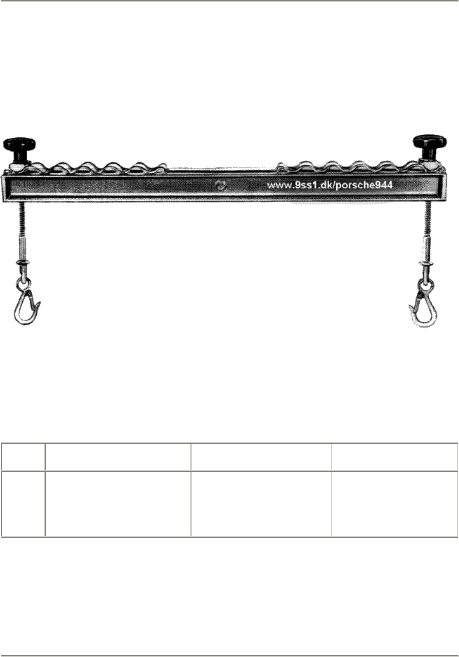
No. Description Special Tool Remarks
Engine suspension
beam
3033
(VW Special Tool)
In conjunction
with workshop
crane, e.g
Bilstein K750 H.
Note:
If necessary, use a commercially available carabiner (load-bearing capacity
650 kg) to connect engine suspension beam to workshop crane.
Printed in Germany - XIII, 1987 Removing and Installing Engine 10 - 101
10 Engine/Crankcase 944
REMOVING AND INSTALLING ENGINE (MANUAL TRANSMISSION)
Remove by lowering engine from car.
The bell housing remains attached
to the engine.
Removing
1.
Align lifting platform pads
beneath jacking points and raise
car.
2.
Place protective covers on
fenders.
3.
Unbolt and remove front wheels.
4.
Disconnect battery/bodywork
ground lead. Disconnect battery
positive lead. Disconnect wire
harness and push both cables with
rubber grommets through splash
wall. Open cable clips.
5.
Unbolt panel in passenger-side
footwell and remove. Unbolt
carrier plate for DME control
unit and disconnect control-unit
plug. Disconnect 8-pin connector.
6.
Slacken hose clamp for fuel
return line and disconnect hose.
Disconnect fuel feed while
countering. Detach cable from
tempostat serve motor. Disconnect
series resistor/injection nozzle
connector.
10 - 102 Removing and Installing Engine Printed in Germany
944 Engine/Crankcase
10
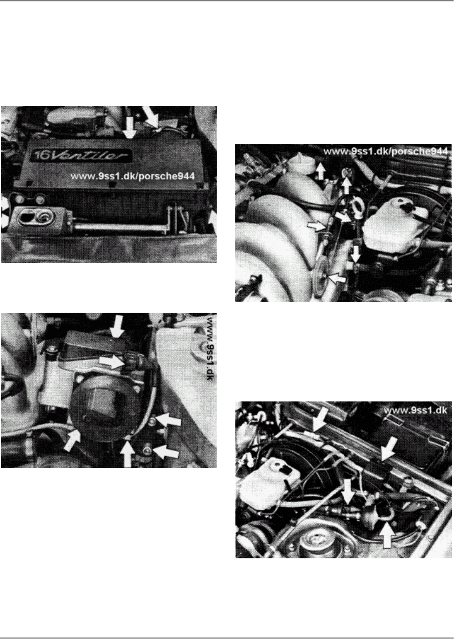
7.
Disconnect breather hose for
toothed helt cover at rear of
lower section of air filter.
Unbolt filter assembly as a unit
and remove.
8.
Remove air-flow sensor.
9.
Slacken and remove
ignition-distributor cap and
rotor. (Mark installation
position of rotor). Remove oil
filter and ATF reservoir.
10.
Remove throttle valve actuating
cable complete with reversing
roller and holder. Disconnect
oxygen sensor plug connector.
Slacken hose clamps at intake
manifold and brake booster and
disconnect hoses.
11.
Remove cable clips from
bulkhead. Disconnect two-pin and
multi-pin connectors. Disconnect
vacuum hose from tank breather
valve.
Printed in Germany - XIII, 1987 Removing and Installing Engine 10 - 103

10 Engine/Crankcase 944
12. Remove engine underguard.
13.
Open coolant drain plug and
catch coolant in a suitable
container. Disconnect alternator
breather hose.
14.
Disconnect coolant hose at
bottom right of radiator from
engine and remove. Catch any
coolant which may be left.
15.
Disconnect electric leads from
fan motors, detach fan-motor
bracket from radiator and remove
by lowering from car.
16.
Slacken coolant hose and
breather hose from top left of
radiator and remove. Disconnect
electrical connection from
temperature switch to radiator.
Disconnect coolant hose from
expansion tank and remove.
17.
Disconnect radiator at brackets
and remove radiator by lowering
from car.
18.
Attach support beam 10-222 A to
front transport bracket of
engine and hold engine in
installation position. Check
that beam is correctly attached.
10 - 104 Removing and Installing Engine Printed in Germany
944 Engine/Crankcase
10
19.
Detach Poly-rib belt tensioner
from air-conditioning compressor
and remove belt. Remove
compresor from bracket and place
to one side. (Do not disconnect
refrigerant hoses).
20.
Unbolt stabilizer with bracket
from body and from control arms
and remove. Disengage left and
right tie rods.
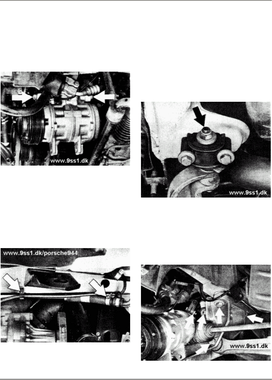
21.
Slacken hose clamps between ATF
cooler and steering and
disconnect line.
22.
Disconnect servo pump from
bracket, moving spacer sleeve
forward to remove. Leave servo
pump hanging from steering.
23.
Disconnect left and right
control arms from front-axle
traverse and rear bearings and
pull forward to remove. (Do not
slacken bolts in bearing bracket).
24.
Unbolt universal joint from
steering detach hydraulic motor
mount from engine supports and
lower front-axle cross member
complete with steering and servo
pump from car.
Printed in Germany - XIII, 1987 Removing and Installing Engine 10 - 105
10 Engine/Crankcase 944
25.
Disconnect leads from starting
motor and remove starting motor.
26.
Remove clutch actuating cylinder
from bell housing. (Leave line
connected). Unbolt and remove
holder for line from upper
crankcase half.
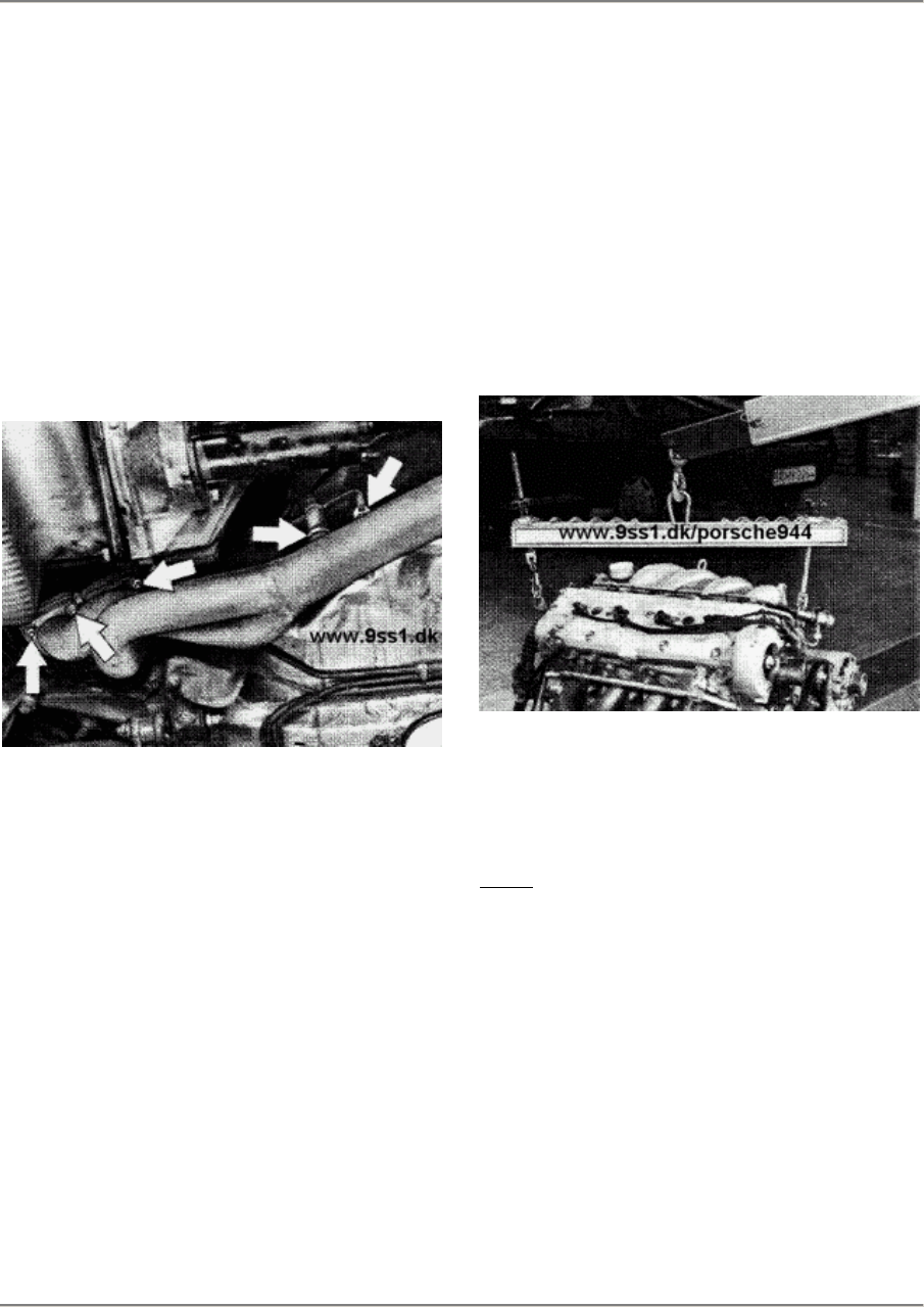
27.
Disconnect exhaust from flange of
exhaust manifold and disconnect
exhaust extraction line. Remove
oxygen-sensor cable from bodywork.
28.
Disconnect flange downstream of
catalytic converter and suspension and
remove system.
29.
Remove upper transaxle/bell
housing mounting bolts.
30.
Disconnect coolant hoses for
heating above exhaust manifold
and from cylinder head.
31.
Attach VW Special Tool 3033
suspension beam to transport
bracket of engine as follows:
Pulley end:
Flywheel end:
Position 2
Position 12
In position 2, the threaded rod is
beneath" the suspension beam. In
position 12, the threaded rod is
"above" the beam.
32.
Tighten workshop crane e.g.
Bilstein K750 H slightly to take
part af engine weight and remove
support beam 10 - 222A.
Note:
Threaded rod af support beam
10 - 222A remains in front
suspension eye.
33.
Remove lower transaxle/bell
housing mounting bolts.
10 - 106 Removing and Installing Engine Printed in Germany
944 Engine/Crankcase
10
34.
Pull engine forward, push rubber
sleeve out of firewall toward
engine compartment and
carefully
pull wire harness out of
passenger-side footwell.
35.
Separate engine from central
tube/central shaft and lower
from car.
Installing
Note the following:
1.
Carefully feed wire harness for
DME control unit, 8-pin connector
and multi-pin connector into
passenger-side footwell.
2.
Begin by screwing transaxle/bell
housing mounting bolts into
place, but do not tighten.
Note:
Do not tighten mounting bolts fully
until hydraulic motor bearing has
been attached to the front-axle
cross member. Tightening torque of
mounting bolts: 42 Nm (31 ftlb).
3.
Install control arms, pressing
sleeve in rubber-metal bearing
down slightly to facilitate
installation.
4.
Place a 4mm thick steel washer in
each of the threaded connections
between the right-hand engine
support (viewed in the forward
direction of travel) and the
hydraulic motor bearing.
5.
Check that the radiator is
correctly seated on the rubber
mounts.
6.
Tighten nuts and bolts to the
specified torques.
Tightening torques:
Stablizer to
aluminium control arm
25 Nm (18 ftlb)
Track rod to
steering knuckle
(locknut)
50 Nm (37 ftlb)
Steering -
universal joint 30 + 5 Nm (22 +
3.6 ftlb)
Control arm to
cross member 65 Nm (48 ftlb)
Cross member
to body 85 Nm (53 ftlb)
Printed in Germany - XIII, 1987 Removing and Installing Engine 10 - 107
10 Engine/Crankcase 944
7.
Refill system with coolant and
bleed system.
8.
Fill reservoir with ATF and bleed
steering system.
9. Run engine until it reaches
operating temperature, check
engine-oil level and coolant
level, top up if necessary.
10 - 108 Removing and Installing Engine Printed in Germany
944 Engine/Crankshaft, Pistons
13
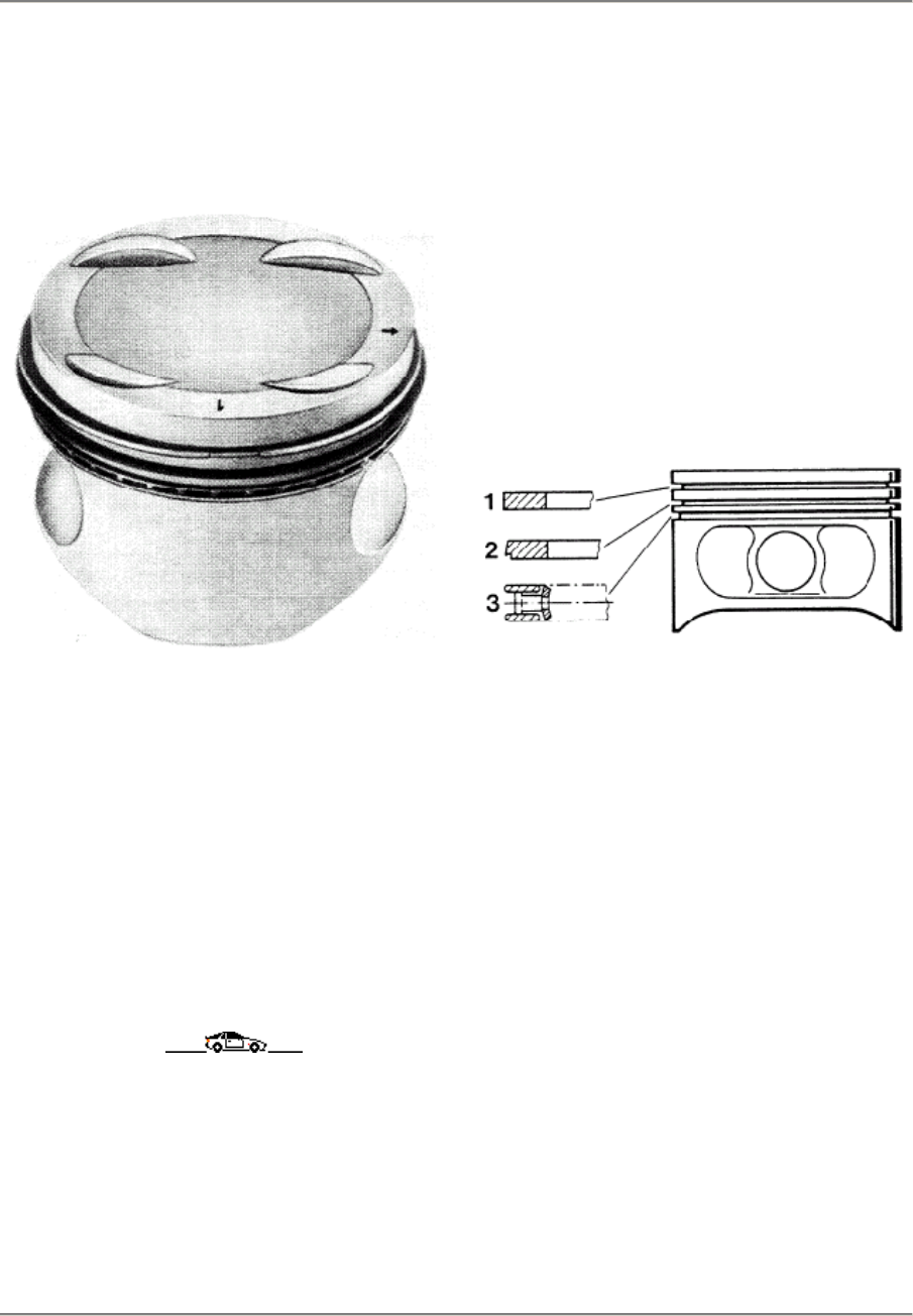
PISTONS. '87 MODELS ONWARD
(16-VALVE ENGINES)
Engine M 44.40 worldwide
Compression: 10.9 : 1
Nominal dia. 100.00 mm
An arrow pointing toward the belt
pulley indicates the installation
position.
1 -
2 -
3 -
Plain compression ring.
chrome-plated
Oil scraper ring
Three-
part oil wiper ring
Printed in Germany - XIII, 1987 Notes on Assembly, Pistons,
'87 Models Onward 13 - 101

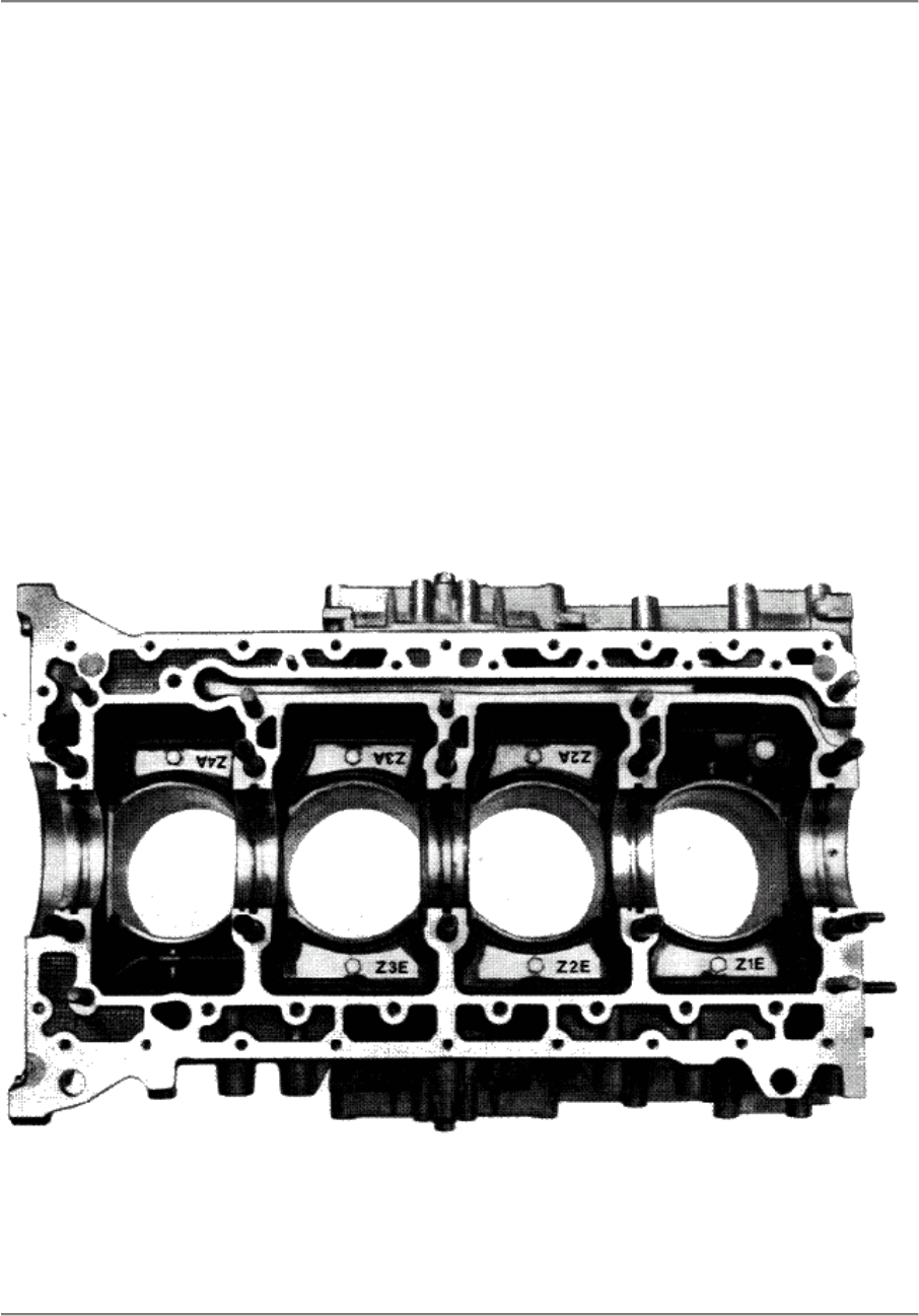
13 Engine/Crankcase, Pistons 944
Checking pistons and cylinder bores
Motortype M 44.40
Repair Stage Piston Ø
(mm)
Fa. Kolbenschmidt
Cylinder bore dia.
(mm) tolerance group
code
Standard size 99.980
99.990 +- 0.007
100.000
100.000
100.010 +- 0.005
100.020
0
1
2
Oversize 1 100.480
100.490 +-0,007
100.500
100.500
100.510 +- 0.005
100.520
I 0
I 1
I 2
Checking pistons
Measure approx. 61 mm from piston crown,
90° offset from piston pin axis.
Checking cylinder bores
Measure approx. 61 mm from upper edge of
cylinder bore, transverse to engine block.
Mount lower crankcase section and tighten
bolts to specified torque for measuring.
Note
It recommended that the stocks of the relevant tolerance group are checked befare machining
the cylinders. If necessary, hone to the piston size available.
In some cases, certain tolerance groups may be in short supply.
13 - 102 Checking pistons and cylinder bores
Printed in Germany - XXV, 1992
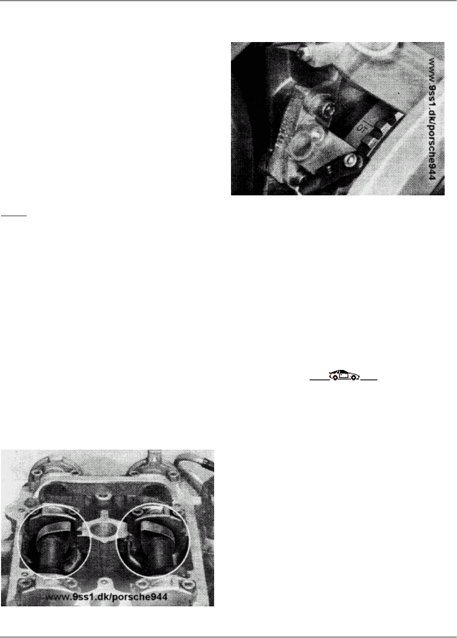
944 Engine/Crankshaft, Pistons 13
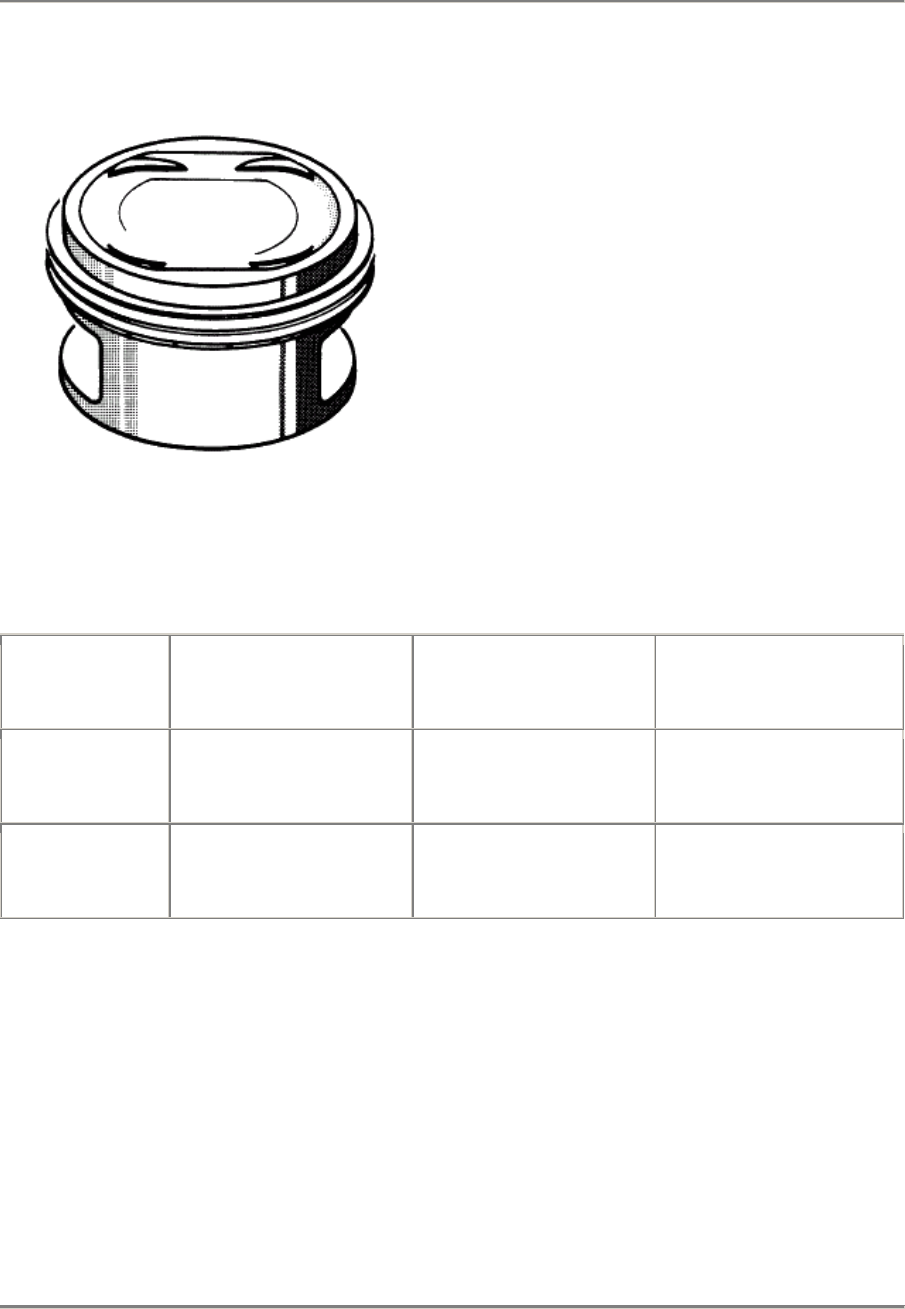
Pistons from Model 89 onwards
Engine M 44. 41 (3.0 I) worldwide
Compression ratio: 10.9 : 1
Nominal Ø 104.00 mm
The installation position is indicated by the
enlarged intake-valve pockets.
171/13
Checking pistons and cylinder bore
Engine type M 44.41 (3.0 l)
Repair size Piston Ø
(mm)
MAHLE
Cylinder bore
(mm) Tolerance groups
Code
Standard 103.980
103.990 +- 0.007
104.000
104.000
104.010 +- 0.005
104.020
0
1
2
Oversize 1 104.480
104.490 +- 0.007
104.500
1 04.500
104.510 +- 0.005
104.520
I 0
I 1
I 2
Checking pistons
Measure approx. 52 mm from crown of pis-
ton, 90' offset to axis of piston bolt.
Checking cylinder bore
Measure approx. 52 mm from top edge of
cylinder bore, across cylinder block.
For measurement, mount lower crankcase
section and tighten with prescribed tightening
torque.
Note
It is recommended that the stocks of the relevant tolerance group are checked before
machining
the cylinders. If necessary, hone to the piston size available.
In some cases, certain tolerance groups may be in short supply.
Pistons from Model 89 onwards
Printed in Germany - XXV, 1992 13 - 103

13 944
This page are missing or blank in the book !
13 - 104 Blank
944 Engine/Crankshaft, Pistons 13
Assemble cover of centrifugal oil
compartment in upper crankcase
section.
Notes on installation
Model 89 onward,
Engine type M 44.41 (3.0 l)
Note
Under normal conditions. it is not necessary
to remove the cover when overhauling an
engine. If the cover is removed, however, the
bolt area must be heated with a hot-air blower
under all circumstances. Apply Loctite 270 to
hexagon head screws.
Observe coding on the cover.
88/342
Assemble cover of centrifugal oil compartment
Printed in Germany - XIX, 1989 13 - 105

15 944
15 - 100 Blank page

944 Engine/Cylinder
15
This page are missing or blank in the book !
Printed in Germany Unknow page
15 - 101

15 Engine/Cylinder 944
This page are missing or blank in the book !
15 - 102 Unknow page Printed in Germany
944 Engine/Cylinder Head, Valves
15
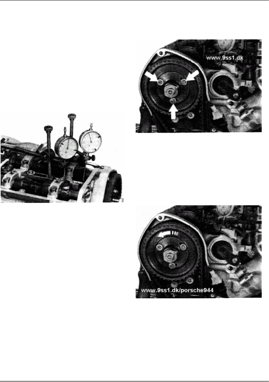
Adjusting with dial gages
2.
Align dial gage with improvised
extension (205 mm long) on piston
crown {cylinder 1). 3 mm
pretension.
Align second gage with hydraulic
tappet of cylinder 1 intake
valve. The dial gage must be
aligned perpendicular to the
intake valve. 3 mm pretension.
3.
Remove distributor rotor and lock
camshaft sprocket with 3
M 5 x 15, to prevent camshaft
sprocket or camshaft turning when
camshaft central bolt is
slackened.
4.
Slacken camshaft central bolt -
note that it is essential to
counter. Slacken temporary
retaining bolts. Turn engine in
direction opposite to direction
of rotation until camshaft
sprocket reaches stop inside
feather-key groove
5.
Tighten temporary retaining bolts
(6 Nm, 4.4 ftlb) and central bolt
(approx. 40 Nm, 30 ftlb).
Printed in Germany - XIII, 1987 Checking an Adjusting
Camshaft Settings
15 - 103
15 Engine/Cylinder Head, Valves 944
6.
Turn the engine in the direction
of rotation until piston reaches
its upper limit af travel.
7. Set dial gage af cylinder 1
intake-valve hydraulic tappet to 0.
8. Turn crankshaft past ignition TDC
(cylinder 1) while observing
cylinder 1 intake-valve dial
gage. Turn engine until gage
shows 1.4 +- 0.1 mm lift.
Note:
Do not turn engine in direction
opposite to direction of rotation.
9. Slacken central bolt and
temporary retaining bolts; while
doing so, ensure that the reading
of 1.4 + 0.1 mm an the dial gage
is not changed.
10.
Now turn crankshaft slowly until
dial gage shows that piston
has reached the upper limit of
travel. With the crankshaft in
this position, the camshafts are
at ignition TDC for
cylinder 4.
11.
Tighten temporary retaining
bolts and central bolt.
Tightening torque of central
bolt: 65 - 70 Nm (48 - 52 ftlb).
12.
Recheck by turning crankshaft
through another 2 turns and
checking setting.
13.
Remove temporary retaining bolts
and install distributor rotor.
15 - 104 Checking an Adjusting
Camshaft Settings Printed in Germany

944 Engine/Cylinder Head and Valve Drive 15
Checking or adjusting camshaft setting for Model 89 onward
Engine type M 44.41 (3.0 l)
Note
The timing has changed with installation of
new camshafts for engine type M 44.41 (3.0 l)
for Model 89 onward.
Setting
Inlet valve cylinder 1
Testing and adjusting value 0.75 +- 0.1 mm
The camshaft is adjusted according to the
same procedure as described on Page
15 - 102.
Checking or adjusting camshaft setting f. Model 89 onward
Printed in Germany - XIX, 1989 15 - 104a

15 Engine/Cylinder Head, Valve Drive 944
Applying the TDC mark on the camshaft sprocket
Engine type M 44.40 / 41 (3.0 l)
Note
Camshaft sprockets available from the spare
parts department do not have a TDC mark.
This TDC mark is applied after the camshaft
timing has been set on the new engine.
1.
Position the new camshaft sprocket over the
old sprocket and transfer the TDC mark to
the new sprocket using a color pencil.
2. Fit new camshaft sprocket and adjust
camshaft timing as described in the Repair
Manual, page 15-102 to 104.
3. After operation 12, page 15-104, has been
carried out, engrave the TDC mark in its
final position on the new camshaft sprocket
using a three-square-file as described on
page 15-102, Fig. 1.
15 - 104b Applying the TDC mark on the camshaft sprocket
Printed in Germany - XXIV, 1991
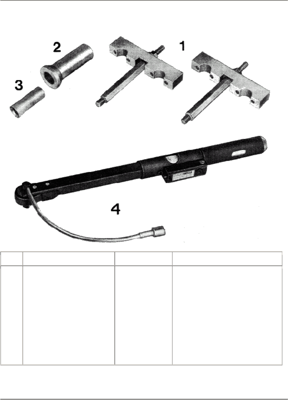
944 Engine/Cylinder Head, Valves
15
TOOLS - REMOVING AND INSTALLING CAMSHAFTS AND CYLINDER HEAD,
DEGREES-OF-TURN METHOD OF TORQUING (16-VALVE ENGINES)
No. Description Special Tool Remarks
1
2
3
4
Assembly bridges for
installing camshafts
Pressure piece for
sealing ring
Assembly drift for
sealing ring
Angle reader
9248
9234
9233
In conjunction with
clamping bolt from
Special Tool 9226
Commercially available
e.g. Stahlwille No. 715/20
Printed in Germany - XIII, 1987 Tools - Removing and Installing
Camshafts and Cylinder Head 15 - 105
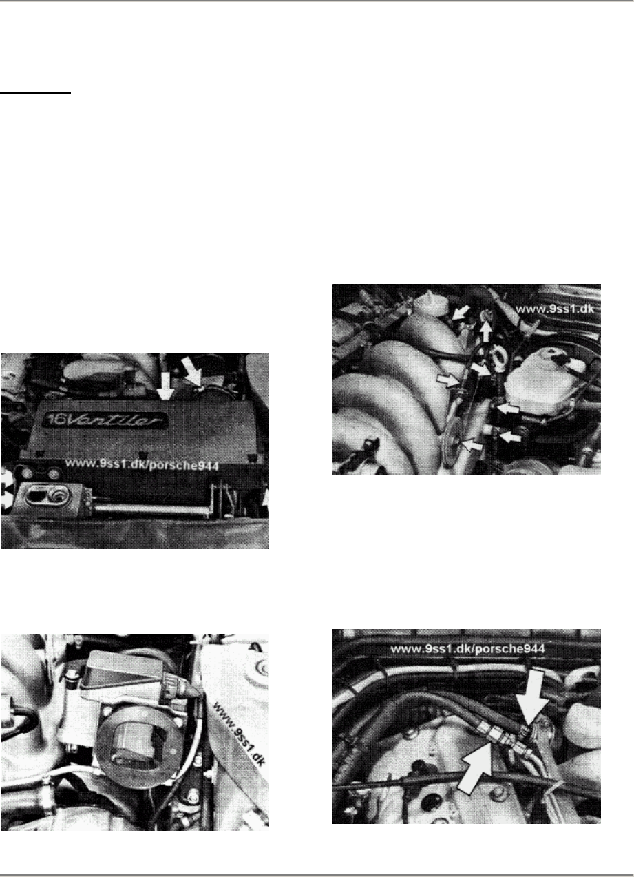
15 Engine/Cylinder Head, Valves 944
REMOVING AND INSTALLING CAMSHAFTS
AND CYLINDER HEAD
Removing:
1.
Align lifting-platform pads beneath
jacking points and raise car.
2. Place protective covers on
fenders.
3. Disconnect ground lead from
battery
4. Disconnect breather hose for
toothed-belt cover from rear of
lower section of air filter. Detach
entire filter assembly and remove.
5.
Remove air-flow sensor and
disconnect support (M 8 bolt)
from intake manifold.
6.
Remove throttle-valve actuating
able complete with reversing
roller and holder. Remove oil
dipstick. Slacken hose clamps at
intake manifold, brake booster
and breather hose and remove.
7.
Remove cover of fuel-distribution
pipe. Slacken hose clamp for fuel
return line and disconnect hose.
Disconnect fuel feed while
countering.
15 - 106 Removing and Installing
Camshafts and Cylinder Head Printed in Germany
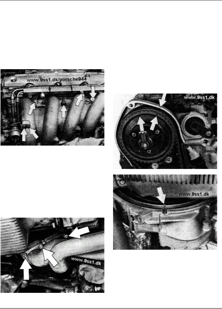
944 Engine/Cylinder Head, Valves
15
8.
Disconnect vacuum hose,
fuel-line-pressure damper
and fuel-distribution pipe
from intake manifold,
disconnect plug from idle
actuator, remove fuel rail with
injection valves and place to one
side.
9. Disconnect throttle-valve switch
connector. Unbolt intake manifold
from cylinder head and remove.
10.
Remove engine underguard. Open
coolant drain plug and catch
coolant in suitable container.
11.
Detach exhaust at
exhaust-manifold flange.
12.
Pull off spark-plug caps and
remove distributor cap. Slacken
hose clamp at ATF reservoir.
13.
Unbolt and remove upper and
lower toothed-belt covers,
front camshaft sprocket bracket
and cylinder-head cover.
14.
Turn engine in direction of
rotation until cylinder 1
ignition TDC is reached.
Printed in Germany - XIII, 1987 Removing and Installing
Camshafts and Cylinder Head
15 - 107

15 Engine/Cylinder Head, Valves 944
15.
Relieve tension of camshaft
toothed belt by slackening nut
A and bolt B, pressing
toothed-belt tensioner against
the pressure of the spring with
Special Tool 9200 and removing
toothed belt from camshaft
sprocket.
16.
Remove distributor rotor. Insert
3 temporary retaining bolts
M 5 x 20 to hold camshaft
sprocket to avoid upsetting
basic camshaft setting when
camshaft central bolt is
slackened.
17.
Slacken central bolt while
countering. Remove camshaft
sprocket.
18.
Remove rear bracket.
19.
Unbolt and remove chain
tensioner.
Note:
Chain-tensioner plunger is spring
loaded. When removing. compress
plunger and after removal hold in
this position with a piece of wire
or a retaining clamp.
15 - 108 Removing and Installing
Camshafts and Cylinder Head Printed in Germany
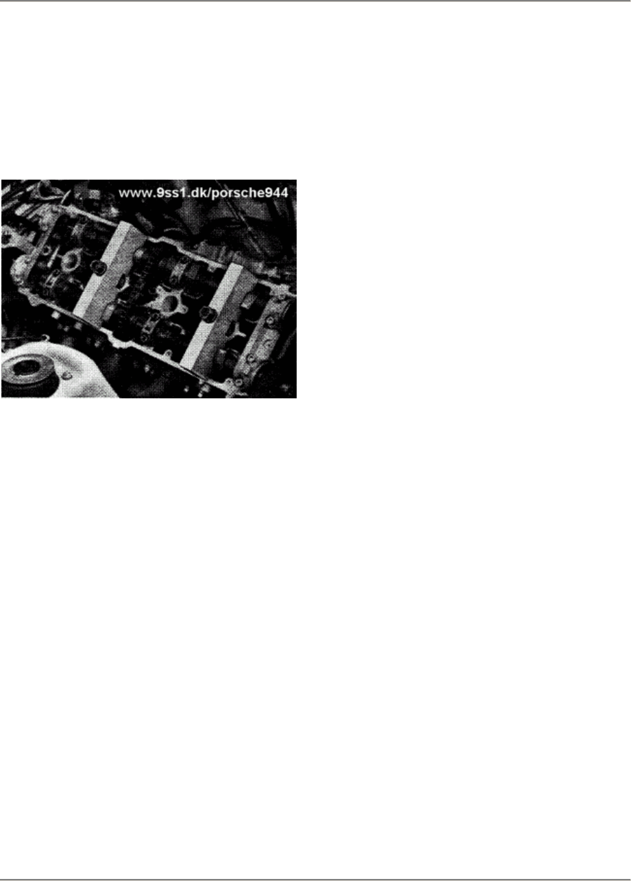
944 Engine/Cylinder Head and Valve Drive 15
20.
Remove bearing cover from cylinders
1 + 3.
Hold both camshafts in the bearings with
Special Tool 9226. Undo and remove front
double bearing bridge and bearing cover.
87 - 422
Note
The rear double bearing bridge may remain
on the cylinder head.
21.
Undo Special Tool evenly, remove both
camshafts with chain and lay together
on
one side.
22.
Undo cylinder head. Undo in sequence:
from outside to inside.
23.
Remove cylinder head.
Note
If oil has been mixed with water, the cylinder
head must be subjected to a thorough visual
inspection (hairline fractures). At the same
time, check the coating system for leaks.
Use
test unit VW 1274 above the expansion tank
for the teak test (max. 1 bar). The camshaft
cover must be removed for visual inspection.
Checking or adjusting camshaft sitting f. Model 89 onward
Printed in Germany - XIX, 1989 15 - 109
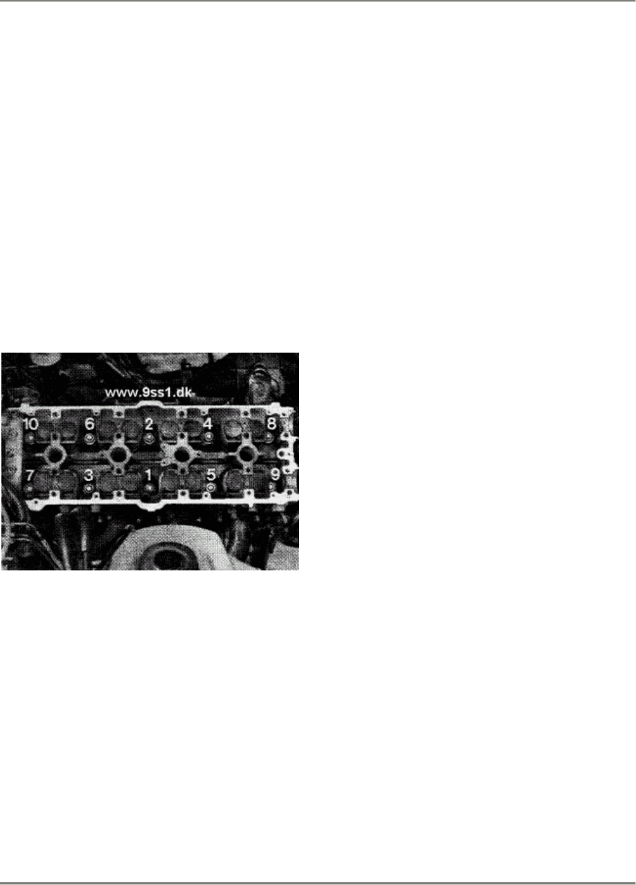
15 Engine/Cylinder Head and Valve Drive 944
Installing and tightening the cylinder head
Model 87 onward
Engine type M 44.40
Note
The cylinder head may be mounted with the
engine installed.
1.
Place the cylinder head gasket in the cer-
rect position.
2. Mount cylinder head
Tightening sequence:
87/420
Opposite to undoing sequence.
Tightening specifications for cylinder
head
Model 87 onward
Engine type M 44.40
1st stage
2nd stage
3rd stage
20 Nm
90° torque angle
90° torque angle
Model 89 onward
Engine type M 44.41 (3.0 I)
Note
The cylinder head has been reinforced by
20
mm in the area of the bearing surfaces for
the
cylinder head nuts. This has altered the
tightening sequence.
Tightening specifications
Model 89 onward
Engine type M 44.41 (3.0 l)
1st stage
2nd stage
3rd stage
20 Nm
60° torque angle
90° torque angle
Note
Never use lubricant when fitting cylinder
head
nuts and washers. Apply a light film of
engine
oil to the stud thread only.
15 - 110 Installing and tightening the cylinder head
Printed in Germany - XXV, 1992
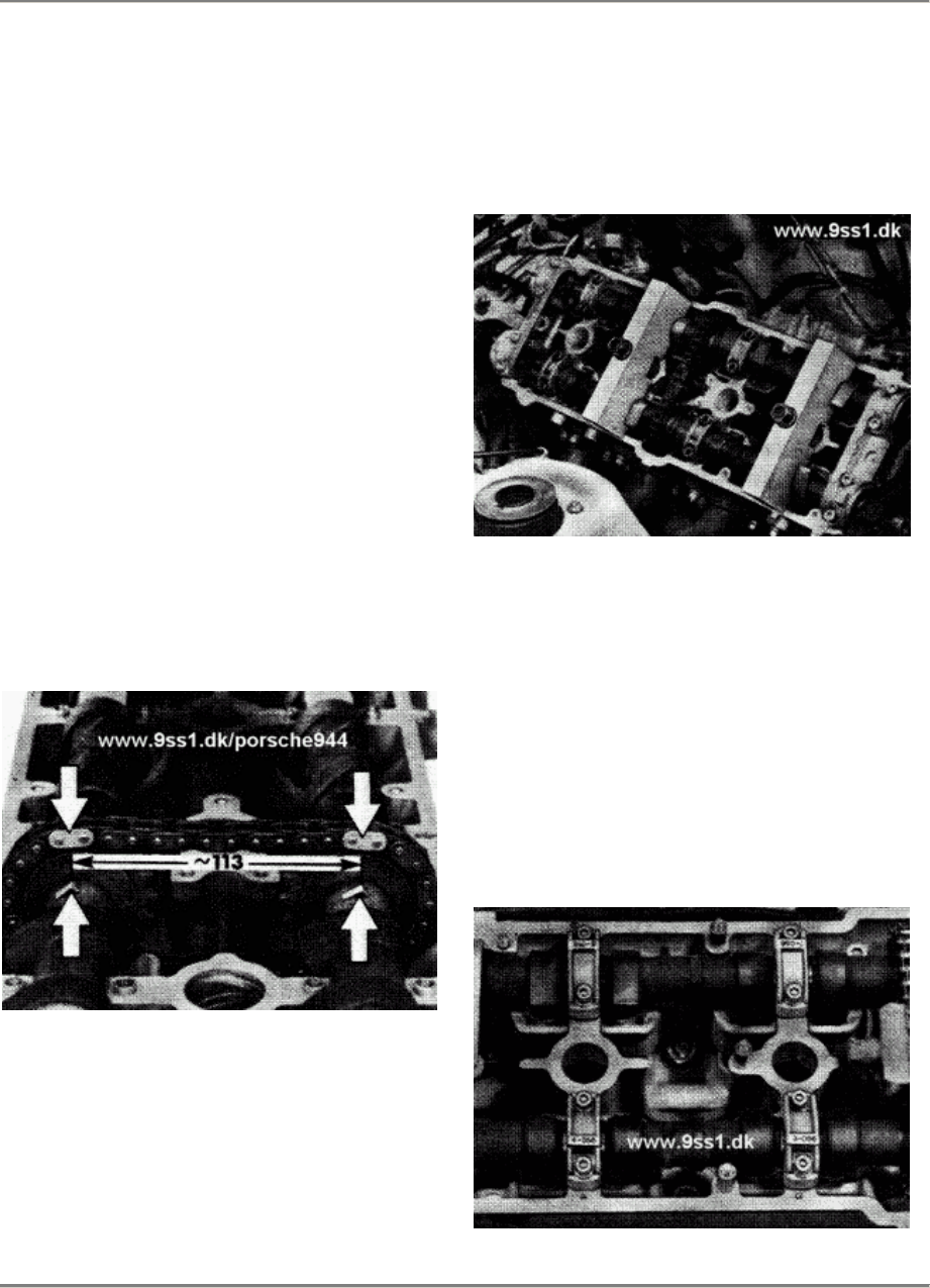
944 Engine/Cylinder Head, Valve Drive 15
Installing camshafts
1.
Turn engine in direction of rotation by ap-
prox. 45° before ignition TDC (cylinder
1).
2. Lay intake shaft and exhaust camshaft in
the timing chain.
3. Place both camshafts in the timing chain
so
that the cast lugs are alignedwith the
marked links of the chain. Oil the bearing
jounals and place in the bearings
carefully
together with the timing chain.
Note
The distance between the marking on the
intake camshaft and the markingon the
exhaust camshaft amounts to 7 outer chain
links; the distance betweenthe cast lugs
measures approx. 113 mm.
11838
4.
Fasten the camshafts to the cylinder
head
with assembly bridges SpecialTool 9248
together with the clamping bolt of Special
Tool 9226.
87/422
5.
Install the bearing bridges and bearing
cover af the camshaft. The
bearingbridges
and cover are production-matched to the
cylinder head and must alwaysbe
installed
as a set. Note the identification code and
pairing number.
Tightening torque for bearing bridges
and
cover 20 Nm.
11804
Installing camshafts
Printed in Germany - XVII, 1988 15 - 111
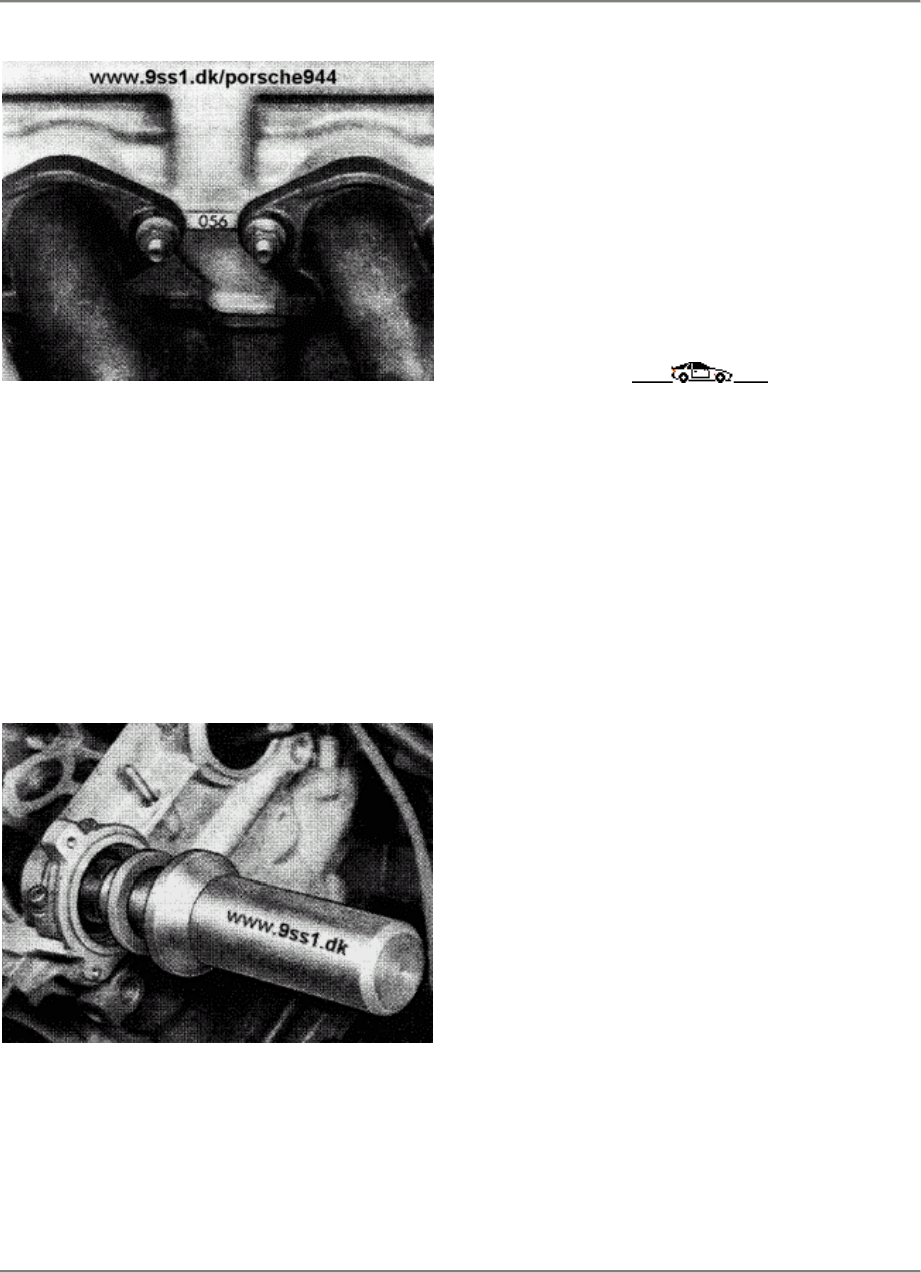
15 Engine/Cylinder Head, Valve Drive 944
11639
6.
Apply Loctite 574 to the sealing surfaces of
the front and rear double bearing bridges.
7. Use the assembly drift, Special Tool 9233
and pressure piece 9234 to drive the
sealing
ring into position at the drive end of the
camshaft. Lubricate the sealing lip before
assembly.
11794
Note
The timing chain must always be replaced
if
the valves have beendamaged by the
piston
as a result of a broken toothed belt.
A thorough visual inspection must be
made
of the sprockets and chain tensioner.
15 - 112 Installing camshafts
Printed in Germany - XVII, 1988
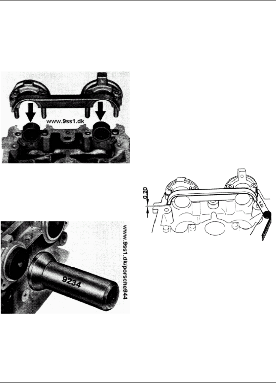
944 Engine/Cylinder Head, Valve Drive 15
Installing Camshaft Seal
1.
Place sealing washers in bearings and
install bearing bridge with Loctite 574.
Tightening torque 20 Nm (15 ftlb).
87/465
2.
After torquing the bearing bridge, install
sealing cover with the aid af Special Tool
9234
86/925
Engine installed
Note:
If the sealing cover af an engine leaks with
the engine installed, the procedure for
installing the cover is as follows:
1.
Place camshafts and sealing washers in
bearing.
2. Apply Loctite 574 to bearing bridge and
install. Place a 0.20 mm feeler gauge
between bearing bridge and cylinder
head
and tighten botts slightly by hand.
928/01
3.
Apply a light film af oil to sealing cover
and
press an by hand. Tighten bearing bridge
to 20 Nm (15 ftlb).
Installing Camshafts Seal
Printed in Germany - XVII, 1988 15 - 112a

15 Engine/Cylinder Head and Valve Drive 944
Camshaft
specifications Worldwide, Model 87
onward Worldwide, Model 89
onward
Engine type
Camshafts
Inlet shaft
Exhaust shaft
Identification code
On the rear
face
Timing
1 mm stroke, zero play
Inlet opens
Inlet closes
Exhaust opens
Exhaust closes
944 S
M 44.40
944.105.277.04
944.105.275.04
277.04
275.04
4° CS
40° CS
36° CS
4° CS
atter TDC
atter BDC
before BDC
before TDC
944 S 2
M 44.41 (3,0 l)
944.105.277.07
944.105.275.09
277.07
275.09
3° CS
47° CS
39° CS
7° CS
atter TDC
atter BDC
before BDC
before TDC
15 - 112b Camshafts specifikations
Printed in Germany - XIX, 1989
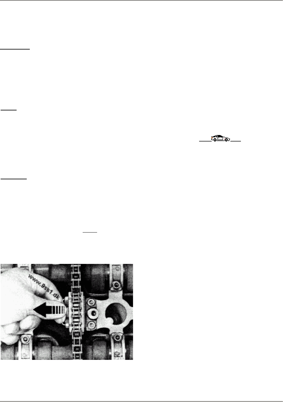
944 Engine/Cylinder Head, Valves
15
REMOVING AND INSTALLING CHAIN
TENSIONER
Removing
Remove hollow screws from cylinder
head and chain tensioner and
remove complete with oil line and
seals.
Note:
Chain-tensioner plunger is
spring-loaded. When removing,
compress plunger and hold in this
position with suitable retainer
(improvised tool).
Installing
1.
Chain tensioner can be installed
without removal of retaining
clamp.
2. The retaining clamp for the
chain-tensioner plunger must be
removed once the chain tensioner
is installed.
3.
When installing the oil delivery
line, install a sealing ring at
both ends of the two hollow
bolts. The check valve is in the
chain tensioner housing.
Tightening torque of hollow
bolts: 10 Nm (7 ftlb)
Printed in Germany - XIII, 1987 Removing and Installing
Chain Tensioner
15 - 113

15 944
This page are missing or blank in the book !
15 - 114
Blank page
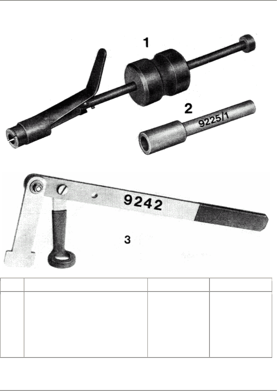
944 Engine/Cylinder Head, Valves
15
TOOLS - CYLINDER HEAD (16-VALVE ENGINES)
No. Description Special Tool Remarks
1
2
3
Puller for valve stem
seals
Press-in tool for valve
stem seals
Valve spring assembly tool
9237
9225/1
9242
Or US 1020
+ US 1020/1
Printed in Germany - XIII, 1987 Tools - Cylinder Head
15 - 115
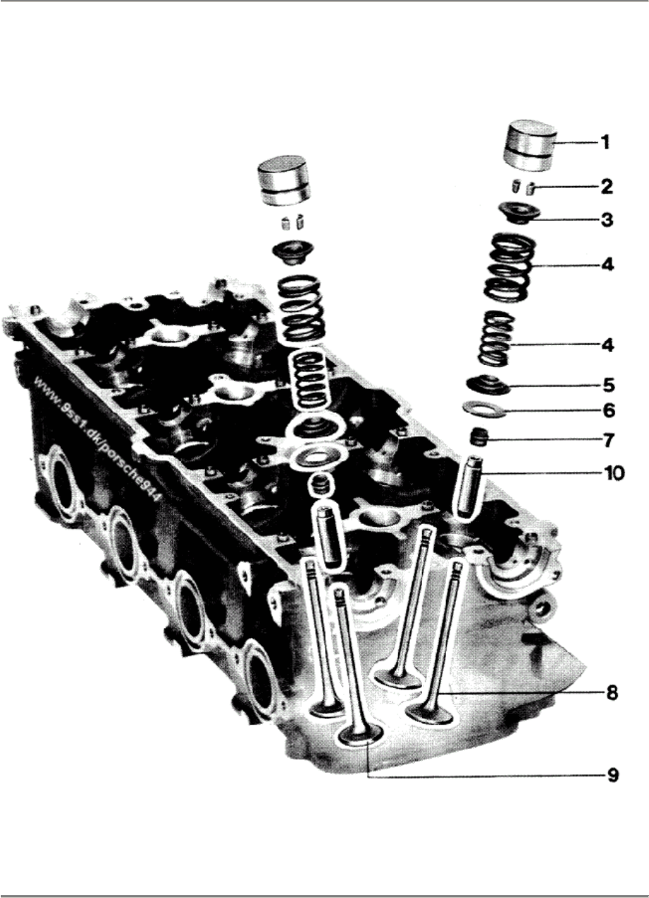
15 Engine/Cylinder Head, Valves 944
DISASSEMBLING AND ASSEMBLING CYLINDER HEAD (16-VALVE ENGINES)
15 - 116 Disassembling and Assembling Cylinder Head Printed in Germany
944 Engine/Cylinder Head, Valves
15
Note When: No. Description Qty.
Removing Installing
1
2
3
4
5
6
7
8
9
10
Hydraulic
valve tappet
Conical valve
keeper
Spring plate
Valve spring
set
Valve spring
support
Washer
Valve stem seal
Intake valve
Exhaust valve
Valve guide
16
32
16
16
16
X
16
8
8
16
Withdraw with a magnet,
do not mix up
Note number
Oil
Check correct
seating
Redetermine if
necessary
Always replace,
drive in with
press-in tool,
Special Tool
9225/1, oil sealing
lip, use drift
Oil valve stem
Oil valve stem
Printed in Germany - XIII, 1987 Disassembling and Assembling
Cylinder Head
15 - 117
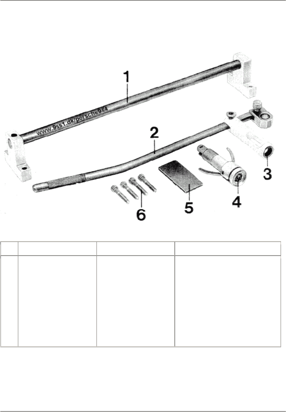
15 Engine/Cylinder Head, Valve Drive 944
Cylinder Head (16 Valves)
Removing and installing valve springs
Tools
87/927
No.
Description Special tool Remarks
1
2
3
4
5
6
Assembly bridge
Lever arm
Magnetic removal head
Assembly head
Spacer
Screws
Supplier: Sauer Hamburg
Supplier: Sauer Hamburg
Supplier: Sauer Hamburg
Supplier: Sauer Hamburg
Supplier: Sauer Hamburg
Commercially available M 8 x 40
Note
If the cylinder head is installed, the lever arm must be angled more accutely.
15 - 118 Removing and installing valve springs
Printed in Germany - XVII, 1988
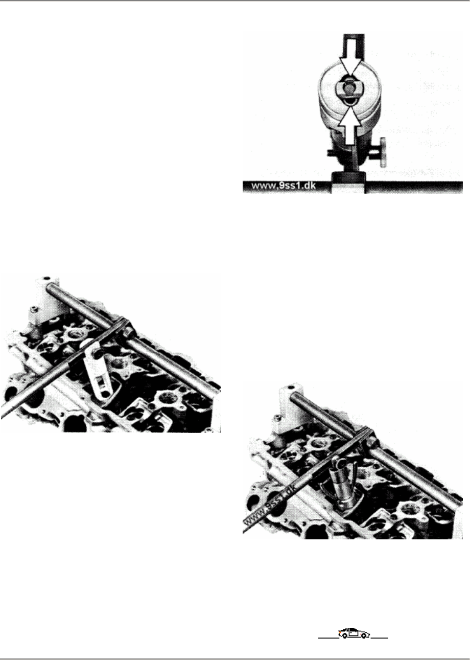
944 Engine/Cylinder Head, Valve Drive 15
Notes on assembly
Remove and install the valve springs with
the special tool supplied by Sauer
1.
Mount the assembly bridge on the
cylinder
head. Secure the cylinderhead to the
work
bench with a screw clamp to prevent
tilting.
2. Fasten the magnetic removal head to the
lever arm. Press the valve
springstogether
in the cylinder head and loosen the
conical valve keeper from the valve shaft
with a small screwdriver.
87/926
3.
All valve spring components can be
pulled
out with the magnetic removal head.
4. Fasten the assembly head to the lever
arm. Prags the tensioningarms toget her
and place the conical valve keepers in
the asssembly head.
87/926
5.
Place washer, valve spring support.
valve
springs and spring plate in the cylinder
head and prags together with the
assembly
head. A small up and down movement of
the lever arm allows the conical valve-
keepers to lock into place. This
movement
also positions the conicalvalve keepers
automatically in the correct location.
87/925
6.
When the conical valve keepers are
locked
in, the tensioning arms of the assembly
head point outwards.
Removing and installing valve springs
Printed in Germany - XVII, 1988 15 - 119
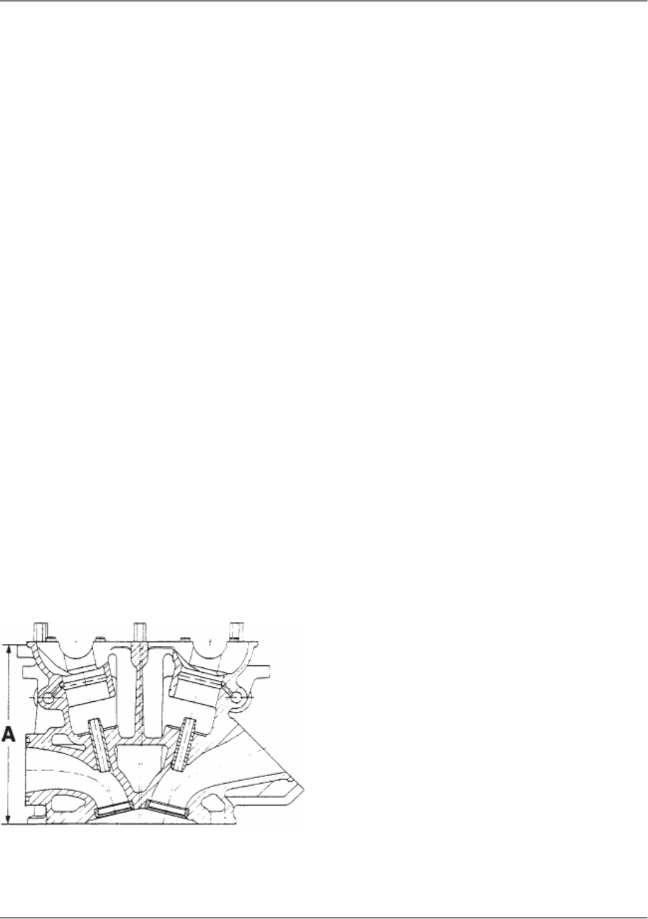
15 Engine/Cylinder Head, Valves 944
Remachining cylinder-head maling face
Checking cylinder head for distortion
Use a feeler gage an a straight edge or a
precision straight edge to check the maling
face of the cylinder head for distortion.
Permissible maling-face uneveness: 0.05
mm
Cylinder heads with distorted maling faces
can be remachined and reused. Permissible
rough atter finishing: 0.03 mm.
Remachining cylinder head
Do not remove mor material from the cylinder
head maling face than is necessary to
achieve a smooth surface. Max. machining
depth 146.6 mm.
Note on machining maling face:
Peak-to-valley = 0.015 mm
If the new-dimension tolerance is exceeded
during machining, a cylinder head gasket
with a thickness of 1.4 mm must be fitted.
Size new
Size worn = 147 +- 0.1 mm
= 146.6 mm
1126-15
Cylinder head refacing dimension and
identification
New dimension
Gasket
Identification
Refacing dimension
Gasket
Identification
: 147 +- 0.1 mm
: 1.1 mm
: none
: 146.8 to 146.6 mm
: 1.4 mm
: N
Identification "N"
To be embossed on exhaust side, between
cylinders no. 2 and 3, on the casting lug
below
the sealing face of the cylinder head cover.
Punch character height "N" = 6 mm
15 - 120 Remachining cylinder-heat mating face
Printed in Germany - XXV, 1992
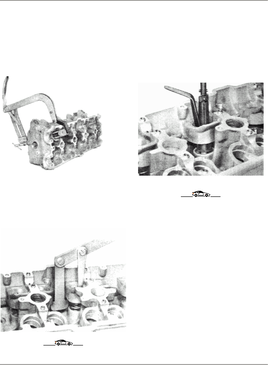
944 Engine/Cylinder Head, Valves
15
NOTES ON ASSEMBLY
REMOVING AND INSTALLING VALVE
SPRINGS
Cylinder head removed
Remove and install valve springs
with US 1020 + US 1020/1.
REMOVING AND INSTALLING VALVE
SPRINGS
Cylinder head installed
Remove and install valve springs
with Special Tool 9242.
REMOVING VALVE STEM SEAL
Remove valve stem seal with Special
Tool 9237.
Printed in Germany - XIII, 1987 Removing and Installing
Valve Springs
Remove Valve Stem Seal
15 - 121
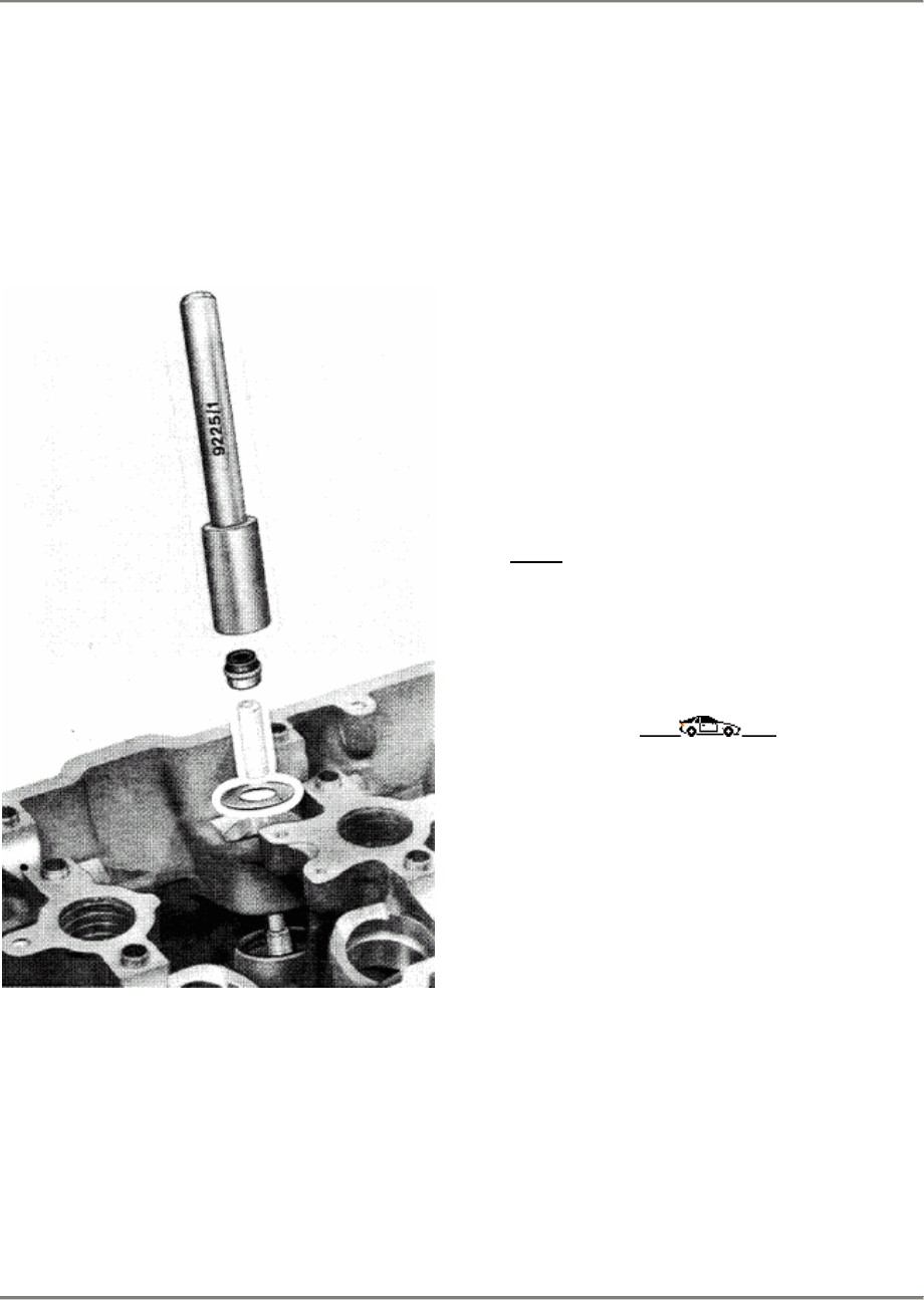
15 Engine/Cylinder Head, Valves 944
INSTALLING VALVE STEM SEAL
Note:
Always remember to place an 1 mm
thick washer on the cylinder-head
face before installing the valve
stem seal.
1.
Lubricate valve stem and install
shaft. Place an 1 mm thick washer
on cylinder-head face. Push drift
over valve stem. Lubricate
sealing lip of valve stem seal
and position on drift. Using
Special Tool 9225/1, carefully
and gently push seal as far as it
will go onto valve guide.
2. The valve stem seal is correctly
seated when Special Tool 9225/1
and washer make contact.
Note:
The assembly drifts are available
as spare parts.
15 - 122 Installing Valve Stem Seal Printed in Germany
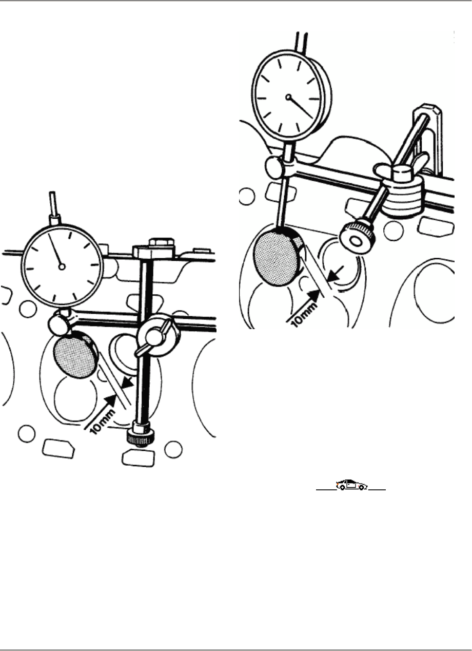
944 Engine/Cylinder Head, Valve Drive 15
Checking the valve guides
1.
Clean the valve guides thoroughly.
2. Use a new valve to measure the tilt
play.
3. Mount bar gate holder VW 387 on the
cylinder head. The dial gaugemust be
aligned parallel to the valve disk.
15/2
15/3
4.
The tilt play is measured with 10 mm
valve
stroke (distance betweenthe valve disk
and
valve seat). Wear limit for intake and
exhaust guides = 0.80 mm.
Checking the valve guides
Printed in Germany - XVII, 1988 15 - 123

15 944
15 - 124 Blank page
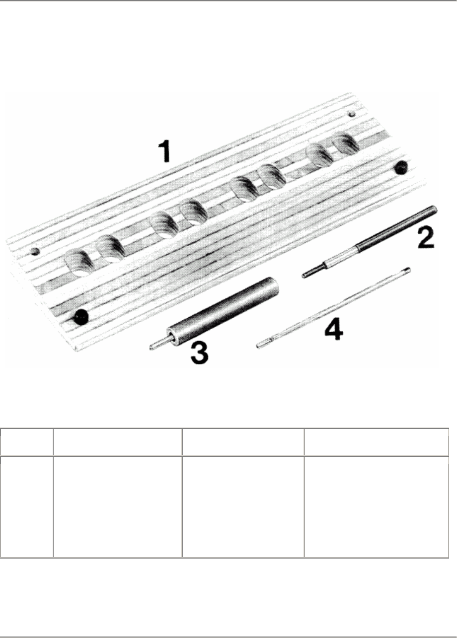
944 Engine/Cylinder Head, Valve Drive 15
Replacing valve guides
Tools
87/918
No. Description Special tool Remarks
1
2
3
4
Ejection base
Plunger
Plunger
Reamer
3120
See drawing
See drawing
See drawing
VW special tool
Replacing valve guides
Printed in Germany - XVII, 1988 15 - 125
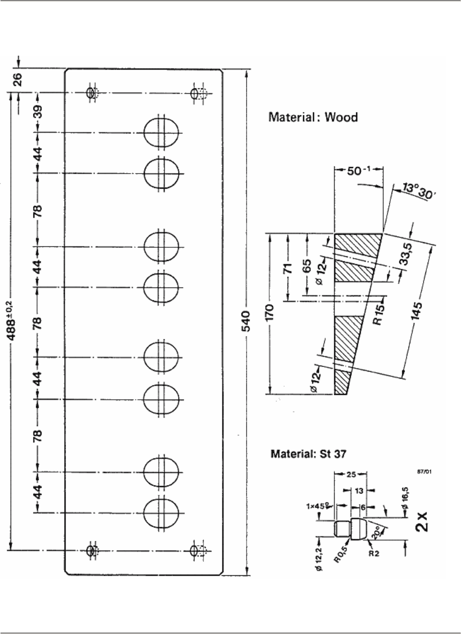
15 Engine/Cylinder Head, Valve Drive 944
Drawing
Plunger to press out the valve guide
15 - 126 Replacing valve guides
Printed in Germany - XVII, 1988
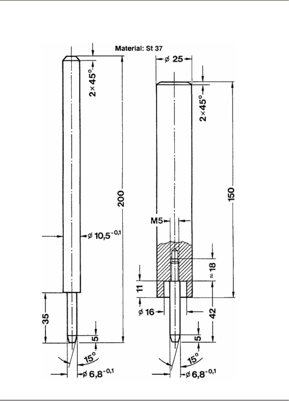
944 Engine/Cylinder Head, Valve Drive 15
Drawing
Plunger to press out the valve guide
Plunger to press in the valve guide
Replacing valve guides
Printed in Germany - XVII, 1988 15 - 127
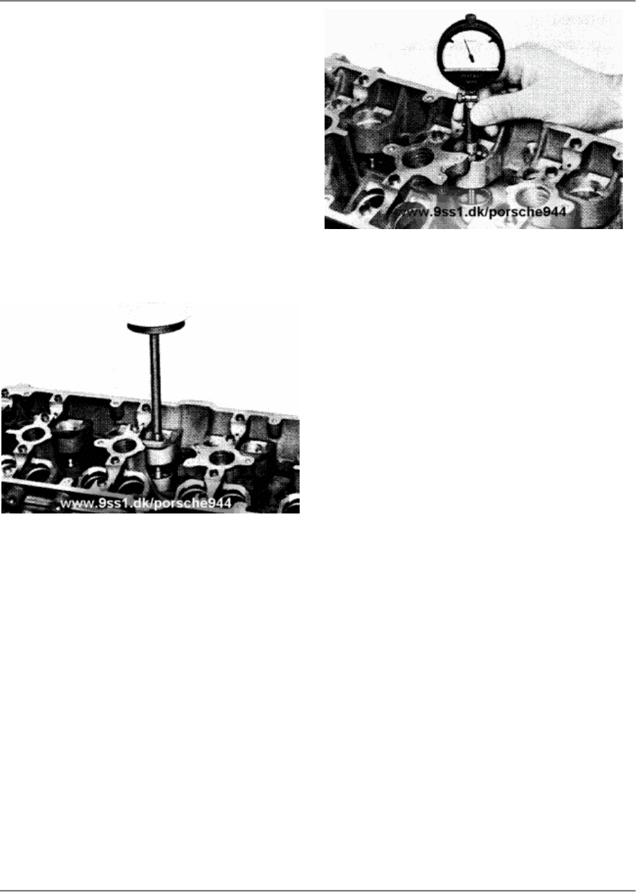
15 Engine, Cylinder Head, Valve Drive 944
Replacing the valve guides
1.
Clean and inspect the cylinder head. It is
inexpedient to replace the valve guides
in
cylinder heads where remachining is no
longer possible on the valve seats or
sealing areas.
2. Lay the cylinder head on the ejection
base.
3. Press out the valve guides from the
camshaft side to the combustionchamber
side with a press.
87/921
4.
Measure the bores in cylinder with an
internat measuring caliper.
87/919
5.
Machine the SP valve guide Part No.
944
104 327 51 (outer diameter 11.26 mm)
accordingly.
The pressing must amount to 0.06 - 0.8
mm
for intake and exhaust valve guides
Example
Bore in the cylinder head measures
11.020 mm. Machine the outside diameter of
the SP valve guide accordingly to 11.080 or
11.10 mm.
Note
A 1 mm thick washer must always be placed
on cylinder-head face before installing the
valve guide.
6.
Heat the cylinder head up to 170 °C
(338°
F). Apply a film of tallow tothe valve
guides.
Position with a light knock, align and.
from
the camshaftside, press into the cylinder
head as far as the stop with aplunger.
Attention
The temperature of 170 °C (338 °F). must
only be maintainedfor a maximum of 90
minutes.
15 - 128 Replacing the valve guides
Printed in Germany - XVII, 1988
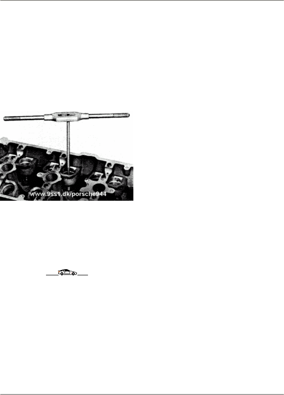
944 Engine, Cylinder Head, Valve Drive 15
7.
Ream the valve guides with
Special Tool 3120
Proceed as follows:
The valve guides must always be reamed with
"petroleum" lubricant Withdraw the reamer
regularly to remove chips. Then finish-ream
the boreagain with a dry reamer.
87/920
8.
The valve seat rings must be remachined
alter replacing the valve guides. It is not
enough to grind in the valves with grinding
paste
Replacing the valve guides
Printed in Germany - XVII, 1988 15 - 129
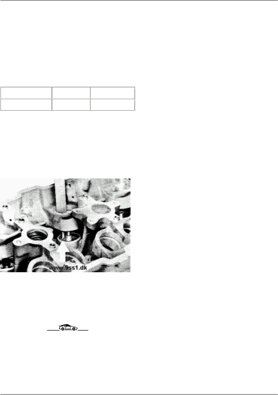
15 Engine, Cylinder Head, Valve Drive 944
Checking the valve seat wear limit
1.
The valve seats in the 4-valve cylinder
heads can be remachined. At the same
time, the wear limit dimension must not
be exceeded as this would mean that the
hydraulic valve tappets may no longer
function correctly.
Wear dimension Intake valve Exhaust valve
As from Model 87 44.4 mm 43.4 mm
2.
This is measured with the valve to be
installed, from the end of the valve shaft to
the contact area af the valve spring
support
in the cylinder head.
11841
3.
The valve must be held firmly on the valve
seat for measurement.
15 - 130 Checking the valve seat wear limit
Printed in Germany - XVII, 1988
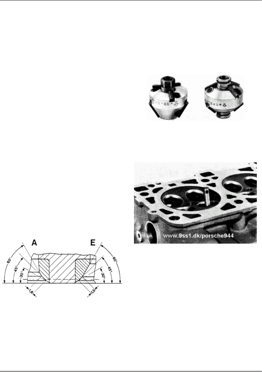
944 Engine, Cylinder Head, Valve Drive 15
Checking and remachining valve seats
Visuel inspection
1.
Check that the valve seat sits securely in
the
cylinder head.
2.
Check the contact pattern. If the valve
does make contact over the emire
surface of the valve seat. remiII the seat
slighdy.
Remachining
1.
Valve seats can be remachined, for
example. with the Neway valve milleror
the Hunger valve seat tuming tool.
2.
Remachine the valve seats with a 45°
seat milling cutter. Then machine the seat
to the prescribed width with a 60°
correction millingcutter. A 30° correction
milling cutter is not required.
Intake seat width 1.5 mm
Exhaust seat width
1.8 mm
1/05
3. Valve seat milling cutter. e.g.
Neway 234 45°
Neway 213 60°
11862
11865
Checking and remachining valve seats
Printed in Germany - XVII, 1988 15 - 131
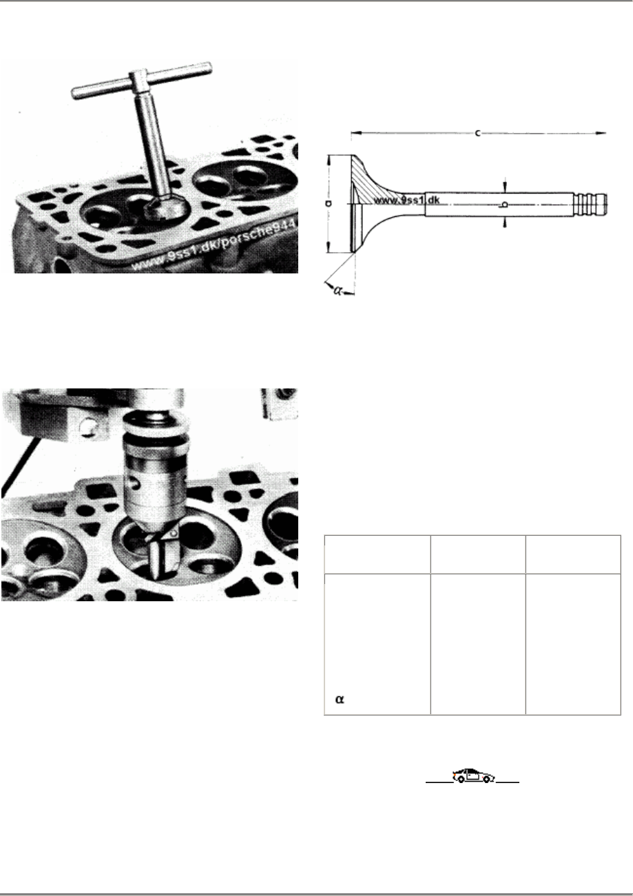
15 Engine, Cylinder Head, Valve Drive 944
11864
4.
Valve seat turning tool, e.g. Hunger
VDSNL
1/45 I.K.
85/151
5.
After milling, grind in the valve seats
lightly
with grinding paste. Check the contact
pattern af the valve seat surface.
Valve dimensions
15/127
Valve dimensions 944 S
As from Model 87
Engine type M 44.40
Dimension Intake Exhaust
a
b
c
37 mm
6.97 mm
114.7 mm
45°
33 mm
6.94 mm
113.7 mm
45°
15 - 132 Checking and remachining valve seats
Printed in Germany - XVII, 1988
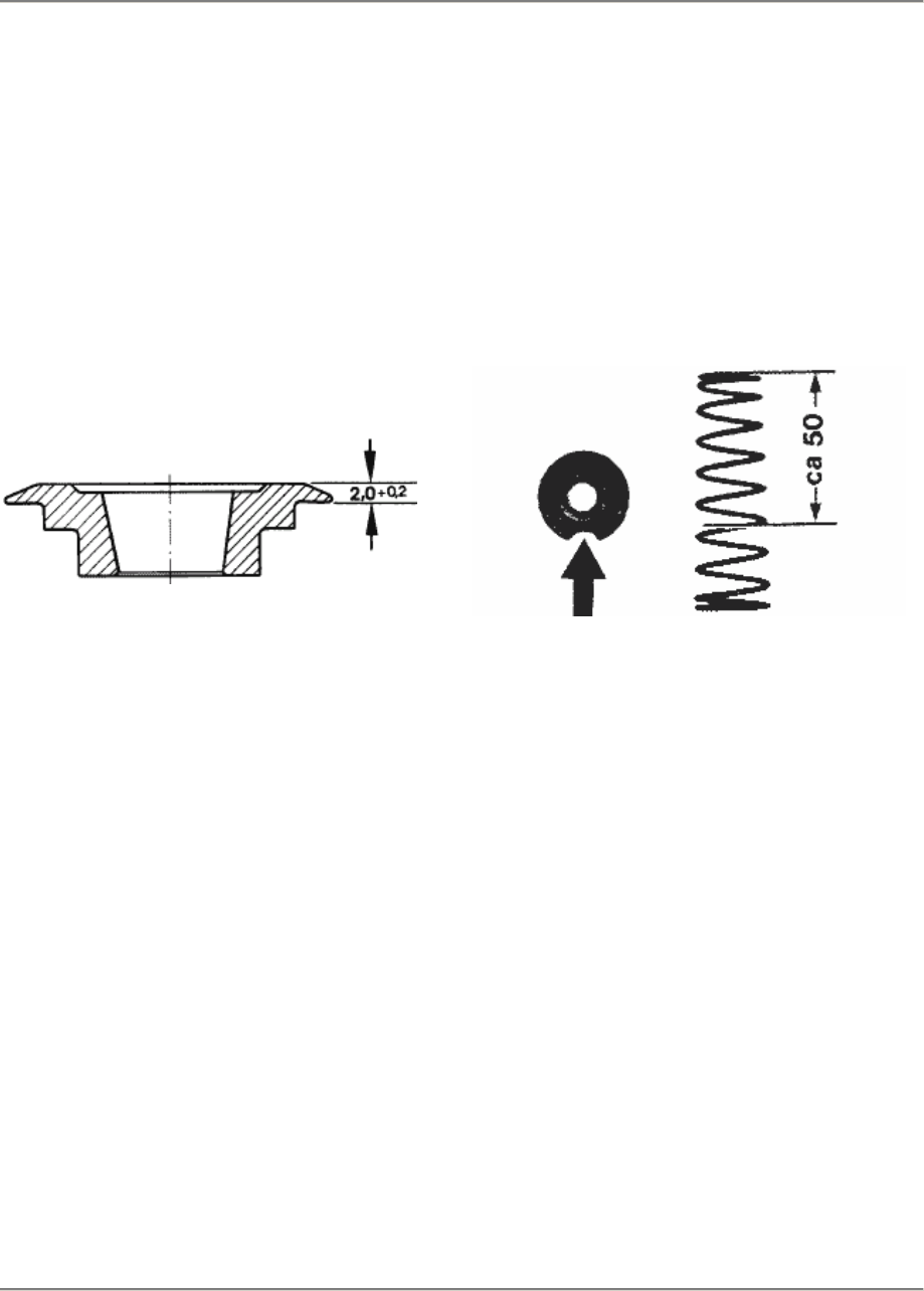
944 Engine, Cylinder Head and Valve Drive 15
Checking and adjusting installation
length of valve springs
Valve springs, Model 87 onward
Engine type M 44.40
Note
When selecting the valve-spring seat (own
construetion) always ensure that the valve-
spring seat is 2.0 + 0.2 mm thick.
1/03
Tool (own construetion)
Valve spring Sp No. 944.105.467.03
Auxiliary spring Sp No. 928.107.171.01
1.
Machine a recess of approx. 10 mm width
into valve-spring seat. Only install valve-
spring seat for measurement.
2.
Shorten the auxiliary spring to approx.
50 mm to ease assembly.
86/927
3.
Install valve and hold in valve seat. Insert
washer. valve-spring seat, auxiliary
spring
and valve-spring seat with machined
recess.
4:
Use Special Tool 9242 to fit the conical
valve keepers.
Checking and adjusting installation length of valve springs
Printed in Germany - XIX, 1989 15 - 133
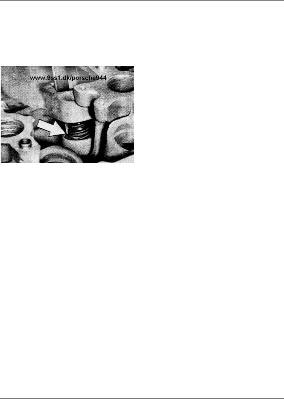
15 Engine, Cylinder Head and Valve Drive 944
5.
Using a depth gauge, measure from the
top surface of the valve-spring seat,
vertically downwards through the recess
to the outer spring contact surface.
86/930
Installation length
Inlet valve
Exhaust valve 38.0 + 0.5 mm
37.0 + 0.5 mm
6.
The installation length can be adjusted
using shims.
7.
The valves must not be mixed up again
after measurement.
Valve spring, Model 89 onward
Engine type M 44.41 (3.0 l)
Note
A new type of valve spring has been
installed
in engine type M 44.41 (3.0 l) from Model 89
onward. The installation length remains
unchanged.
Installation lengths
Inlet valve
Exhaust valve 38.0 + 0.5 mm
37.0 + 0.5 mm
Carry out working procedure Checking and
adjusting installation length of valve springs
as described on Page 15 - 133.
15 - 134
Checking and adjusting installation length of valve springs
Printed in Germany - XIX, 1989
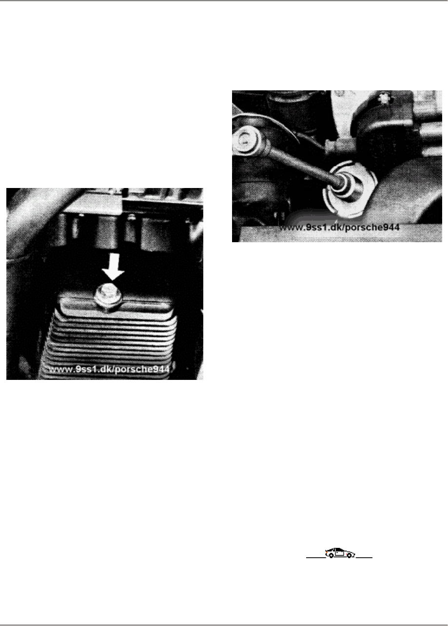
944 Engine/Lubrication
17
CHANGING ENGINE OIL AND ENGINE OIL FILTER (16-VALVE ENGINES)
Preconditioned:
Engine at operating temperature.
1.
Unscrew and remove oil filler cap.
2.
Unscrew oil drain plug from oil pan and
drain engine oil.
3.
Remove oil filter with oil-filter wrench,
Special Tool 9204. Catch remaining oil.
4.
Clean drain plug and never forget to
replace seal. Tightening torque: 50 Nm
(37 ftlb).
5.
Lightly oil gasket of oil filter, screw in by
hand until gasket makes contact, and turn
through one further turn to tighten. To
ensure that filter is correctly seated,
recheck with oil-filter wrench. Tightening
torque (for guidance): 20 Nm (14 ftlb).
6.
Pour in engine oil, run ergine to operating
temperature and check for leaks.
7.
Check oil level with engine switched off.
Printed in Germany - XIII, 1987 Changing Engine Oil
and Engine Oil Filter
17 - 101
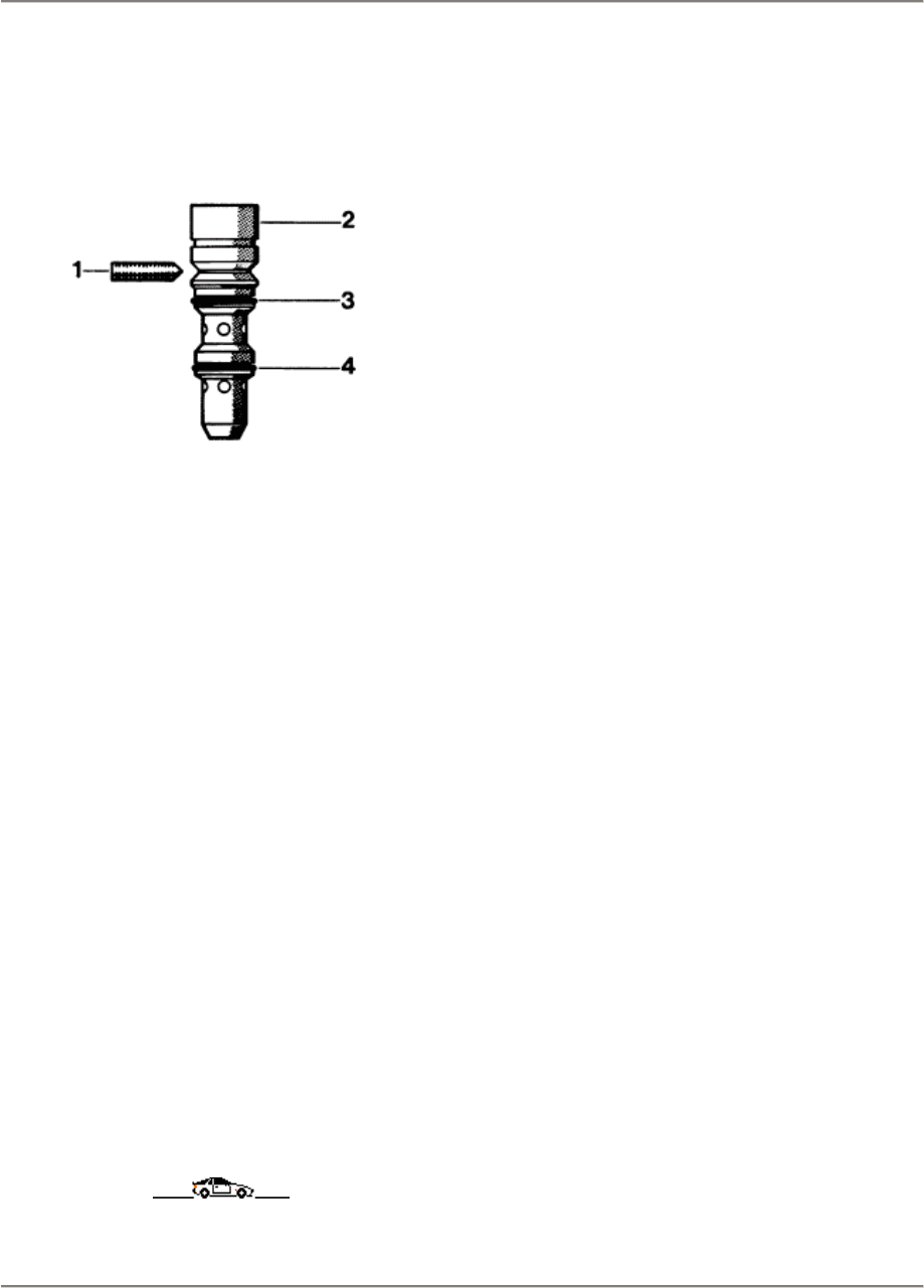
17 Engine, Lubrication 944
Removing and installing the pressure reducing valve
Engine type M44.40
80/17
1 -
2 -
3 -
4 -
Se screw
Pressure reducing valve
O-ring
O-ring
1. Remove the cylinder head cover and
undo
the set screw by 2 rums.
2. Ease the pressure reducing valve out of
the seat with a screwdriverand take out
upwards.
3. Replace the O-rings and apply a light film
of oil before installation.
4. Tighten the set screw carefully until you
can feel the stop, then tum back by 45°.
The screw must not be loose.
(Microencapsulated, renew if necessary).
17 - 102 Removing and installing the pressure reducing valve
Printed in Germany - XVII, 1988
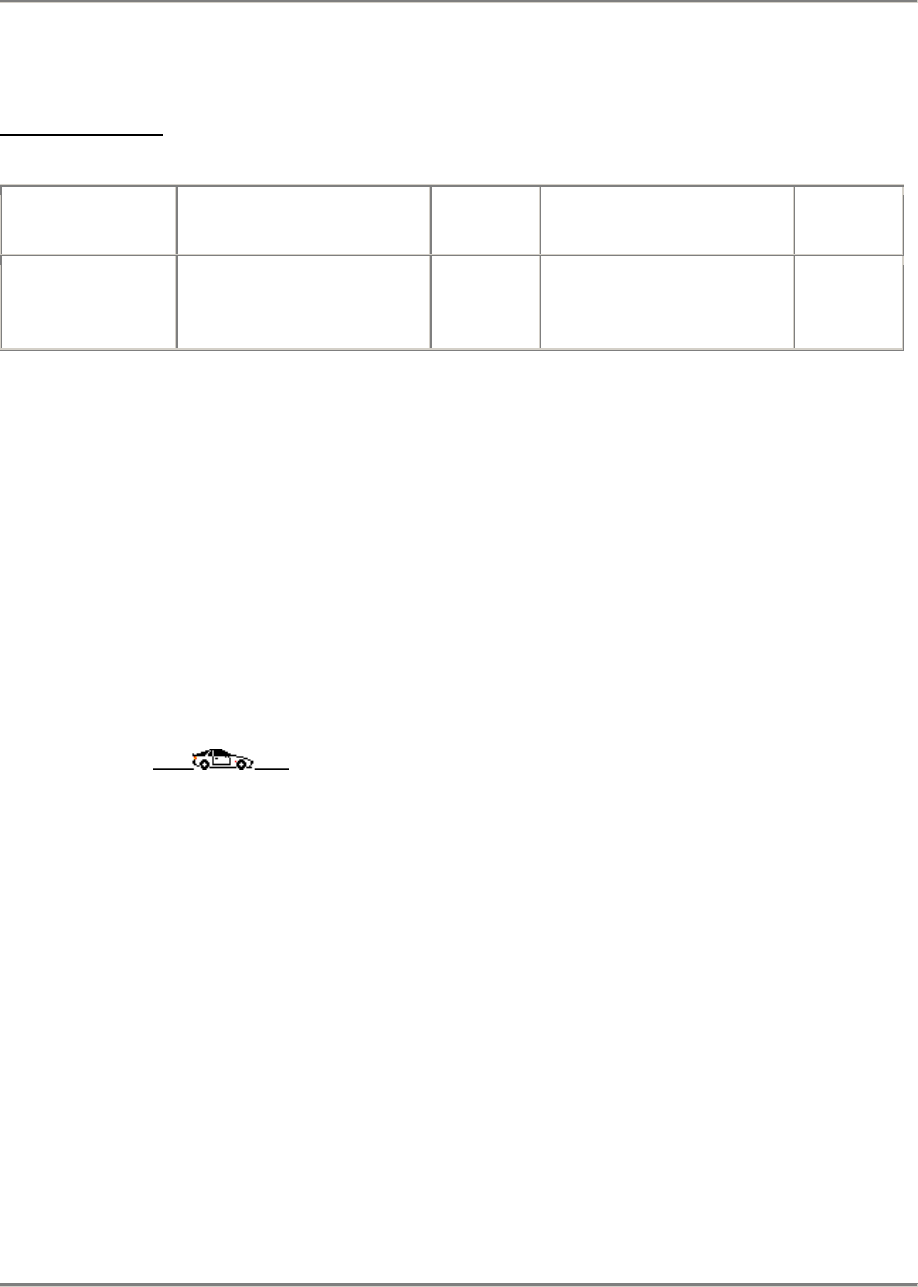
944 Engine/Cooling
19
MIXING TABLE FOR COOLANT
(Average values)
Antifreeze
effective to Antifreeze Agent Water Antifreeze Agent Water
- 25° C
- 30° C
- 35° C
40%
45%
50%
60%
55%
50%
3.1 l
3.5 l
3.9 l
4.7 l
4.3 l
3.9 l
CHECKING HEATING AND COOLING SYSTEM
FOR LEAKS (16-VALVE ENGINES)
1.
Visual inspection for leaks.
2. Check routing of cooling and
heating hoses, look for signs of
porosity, swelling, cracks and
rubbing. Replace damaged hoses.
3. Retighten hose clamps.
Printed in Germany - XIII, 1987 Checking Cooling and Heating
System for Leaks 19 - 101

20 944
20 - 100 Blank Page
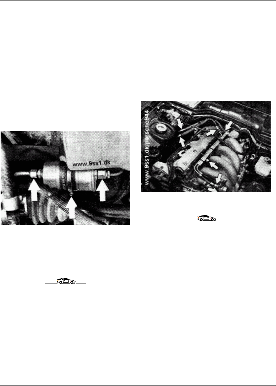
944 Fuel Supply
20
REPLACING FUEL FILTER (16-VALVE
ENGINES)
1.
Disconnect fuel lines, always counter
when slackening threaded connectors.
Catch fuel exiting from lines in a suitable
container.
2.
Slacken retaining clamp and remove fuel
filter.
3.
Install new filter. Direction of flow is as
indicated by the arrow.
CHECKING FUEL AND INJECTION LINES
FOR LEAKS AND LOOSE CONNECTIONS
1.
Visual inspection for leaks.
2.
Retighten union nuts and hose clamp.
Printed in Germany - XIII, 1987 Replacing Fuel Filter, Checking
Injection Lines for Leaks and
Loose Connections
20 - 101
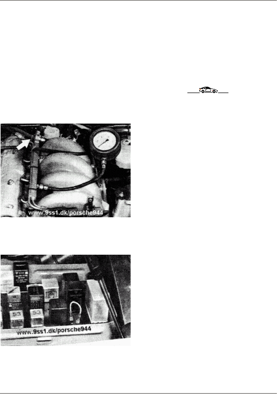
20 Fuel Supply 944
CHECKING DELIVERY RATE OF FUEL PUMP
Precondition:
Fuel filter and power supply OK.
1.
Unbolt fuel return hose from pressure
regulator. Connect a length of
commercially available fuel hose and
place one end in a graduated cylinder
(capacity apprax. 1500 cc).
2.
Disconnect DME relay from central
electrics and, using a length of wire,
jumper terminals 30 and 87 b.
Allow fuel to flow into graduated cylinder for
30 seconds. Minimum delivery rate is 850
cc/30s, if necessary replace fuel pump.
20 - 102 Checking Delivery Rate of Fuel Pump Printed in Germany
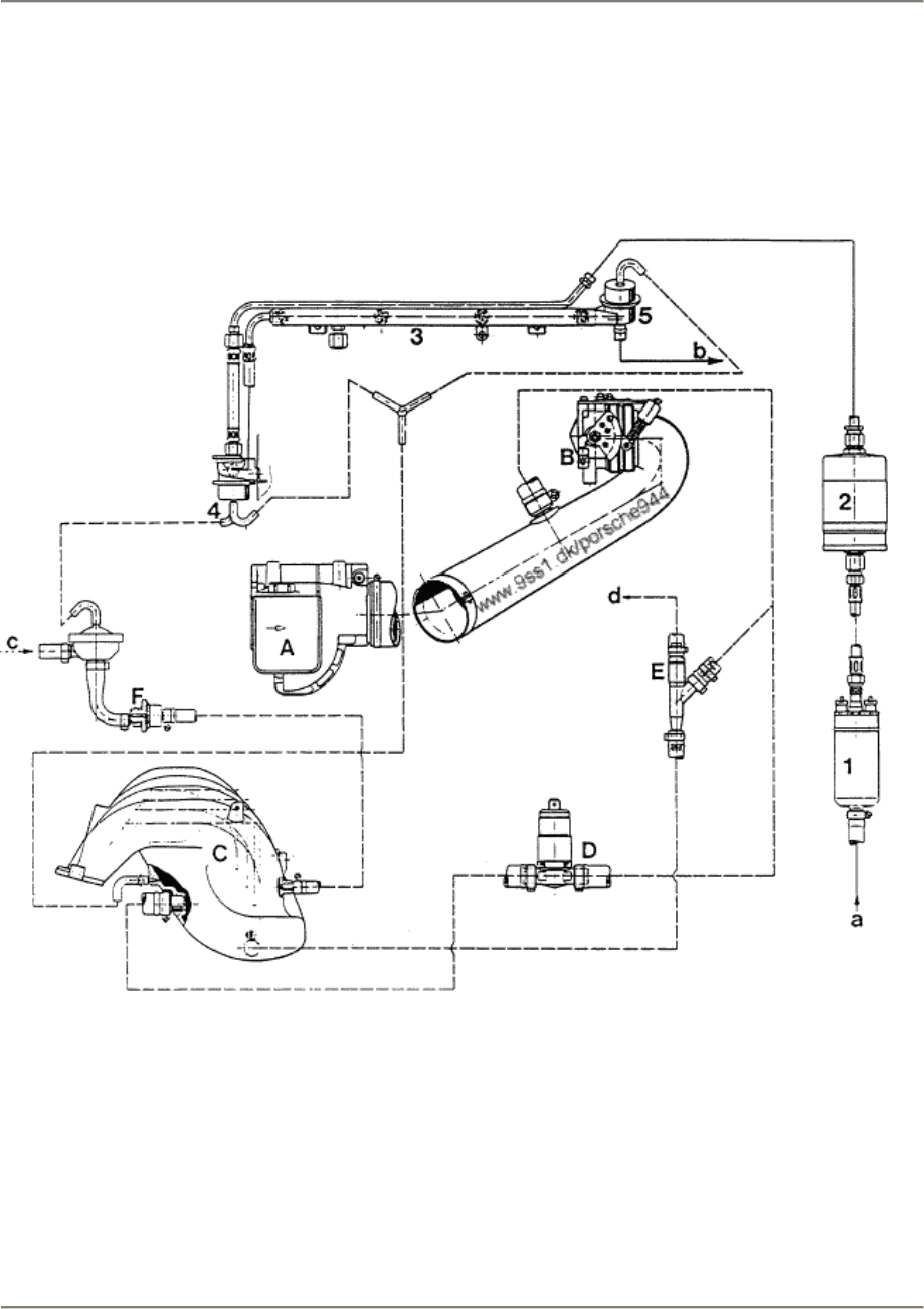
944 Fuel Supply
20
FUEL SYSTEM LINE ROUTING (16-VALVE ENGINES)
'87 MODELS ONWARD
ENGINE TYPE M 44.40
1 Fuel pump
2 Fuel filter
3 Fuel collector tube
4 Pressure damper
5 Pressure regulator
A Air flow sensor
B Throttle valve housing
C Intake tube
D Idle actuator
E Intake jet pump
F Electric tank breather valve
a from fuel tank
b to fuel tank
c from activated charcoal canister
d to brake unit
Printed in Germany - XIII, 1987 Fuel System Line Routing
(16-Valve Engines) 20 - 103

24 944
24 - 100 Blank Page
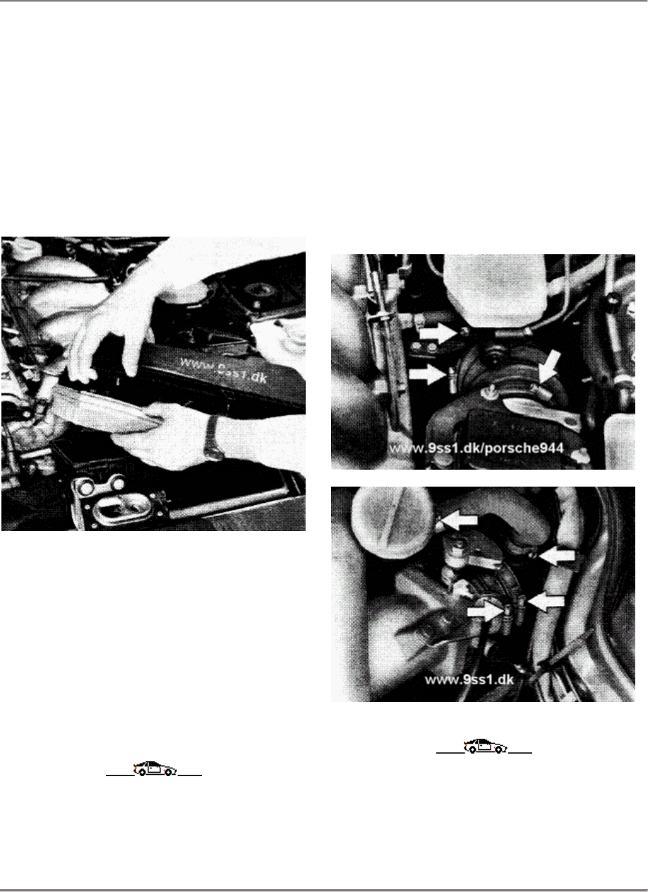
944 L-Jetronic Fuel Injection
24
REPLACING AIR FILTER ELEMENT
(16-VALVE ENGINES)
1.
Use a screwdriver to remove
mounting screws and remove
upper part of air filter.
3.
Remove filter element and
clean inside of lower half of
air-filter housing with a
lint-free cloth
4. Insert filter element, place
housing cover in position and
tighten mounting screws. Check
that upper part of air filter
is correctly seated.
CHECKING INTAKE AIR GUIDE AND
CRANKCASE BREATHER HOSES FOR
LEAKS
AND LOOSE CONNECTIONS
1.
Check all hoses of intake system
for loose connections
2. Retighten hose clamps.
Printed in Germany - XIII, 1987 Replacing Air Filter Element,
Checking intake Air Guide Hoses 24 - 101

24 Air Flow Controlled Fuelinjection 944
Testing and adjusting specifications
Model 87 onward
Engine type M 44.40/41 (3.0 I)
Test Specifikation Remarks
Electric fuel
pump
Min. delivery
rate 850 cm3/30 s
Fuel pressure
(engine stationary)
DEE relay
jumpered
3.8 +- 0.2 bar
Checking value at
idle
approx. 3.3 +- 0.2
bar
Leak test
min. pressure after
20 Min.
2.0 bar
Idle speed
rpm
CO values %
ppm
without catalytic
converter
840 +- 40 **
0.5...1.5
<= 300
with
catalytic
converte
840 +- 40 **
0.4...1.2 *
<= 300 *
**
Idle speed
can only now be
checked. Idle adjust-
ment no longer
applies.
*
Measured upstream at
catalytic converter and
Lambda HC value
probe connector not
separated
CO adjustment no
longer applies.
Note
Carry out working procedure checking delivery rate of fuel pump and checking fuel
pressure as described an Pages 20 - 102 and 24 - 103 respectively.
Tightening torque for cap nut 12 Nm.
24 - 102 Testing and adjusting specifications
Printed in Germany - XIX, 1989
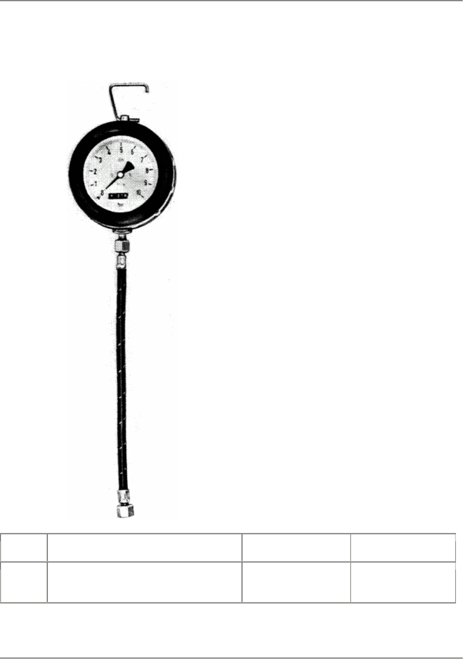
944 L-Jetronic Fuel Injection
24
CHECKING FUEL PRESSURE
TOOLS
No. Description Special Tool Remarks
Pressure gage with hose
from pressure tester P 378 or VW 1318
Printed in Germany - XIII, 1987 Checking Fuel Pressure
24 - 103
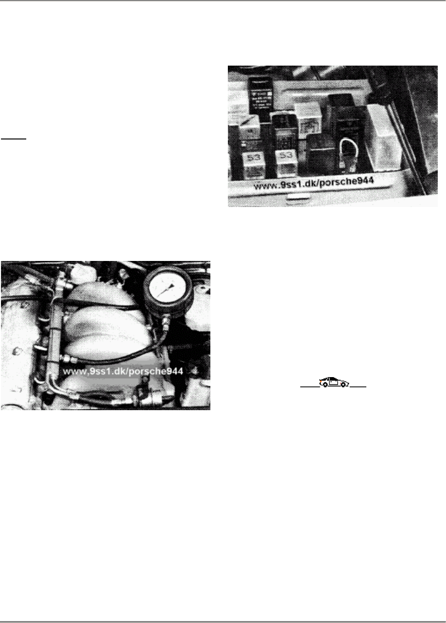
24 L-Jetronic Fuel Injection 944
CHECKING FUEL PRESSURE
1.
Slacken and remove capped nut on
test connection of fuel
distribution line.
Note:
Be careful that sealing ball does
not fall out when capped nut is
removed.
2.
Connect pressure gage with hose
from pressure tester P 378 or VW
1318 to test connection.
3.
Disconnect DME relay from central
electrics and jumper terminals 30
and 87 b with a length of
electric wire. Fuel pump must now
run.
4.
Control value:
Engine stopped 3.8 +- 0.2 bar
(DME relay jumpered)
Engine idling, approx. 3.3 bar
5. Tightening torque of capped nut:
22 Nm (16 ftlb)
24 - 104 Checking Fuel Pressure Printed in Germany
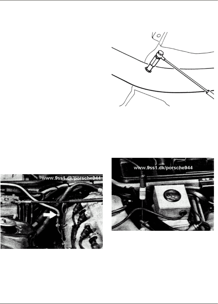
944 Air Flow Controlled Fuel Injection 24
Checking idle speed and CO-
with catalytic converter
Model 87 onward
Engine type M 44.40/41 (3.0 l)
Note
It is no longer possible to adjust idle speed
or
CO on vehicles with catalytic converters. The
Lambda probe remains connected while
chekking idle speed and CO.
Checking preconditions
Engine in perfect mechanical condition. Con-
sumers must be switched off during checks.
Carry out checks as quickly as possible to
ensure that the intake paths do not heat up
thus falsifying the CO value. Ambient
temperature 15 - 35° C.
1.
Fit standard exhaust adapter to the test
connector of the catalytic converter.
Engine type M 44.40
86/463
Engine type M 44.41 (3.0 l)
173-24
2.
Warm engine up to operating
temperature.
(70 - 90° C oil temperature.) Use the oil-
temperature tester, Special TooIs 9122
and 9122/2.
85/114
3.
Do not separate the connection for the
Lambda probe. Connect CO tester and
separate speedometer according to the
manufacturer's specifications.
CO reference value 0.4...1.2%
Idle speed 840 +- 40 rpm
Checking idle speed and CO- with catalytic converter
Printed in Germany - XIX, 1989 24 - 105
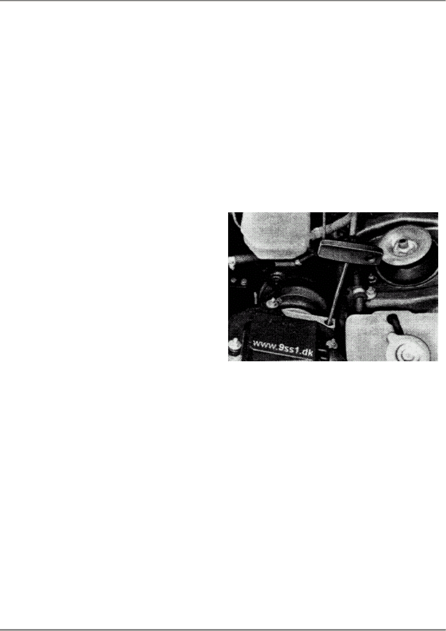
24 Air Flow Controlled Fuel Injection 944
Checking idle speed and CO
without catalytic converter
Model 87 onward
Engine type M 44.40/41 (3.0 l)
Note
It is no longer possible to adjust the idle
speed. The throttle valve connector
adjustment therefore no longer applies.
Idle/CO adjustment
Adjustment preconditions
Engine in perfect mechanical conditions.
Consumers must be switched off during
adjustment work. Carry out adjustment as
quickly as possible to ensure that the intake
paths do not heat up thus falsifying the CO
value. Ambient temperature 15 - 35° C.
1.
Warm engine up to operating
temperature.
(70 - 90°C oii temperature). Use oil
tempe-
rature tester, Special Tools 9122 and
9122/2.
2.
Check CO value. If the CO value is not
within the prescribed tolerances. correct
the setting at the air-flow sensor. Remove
the sealing plug in the access bore to
the CO adjusting screw.
Engine type M 44.40
Standard screwdriver for 3 mm Allen screw.
Engine type M 44.41 (3.0 l)
Standard angled screwdriver for 5 mm
Allen screw.
Illustration shows engine type M 44.40
86/512
CO setting: 0.5...1.5 %
Turn to the right - richer mixture
Turn to the left - leaner mixture
Checking idle speed.
1.
Connect separate speedometer
according
to manufacturer's specifications.
Idle speed 840 +- 40 rpm
24 - 106 Checking idle speed and CO- with catalytic converte
Printed in Germany - XIX, 1989
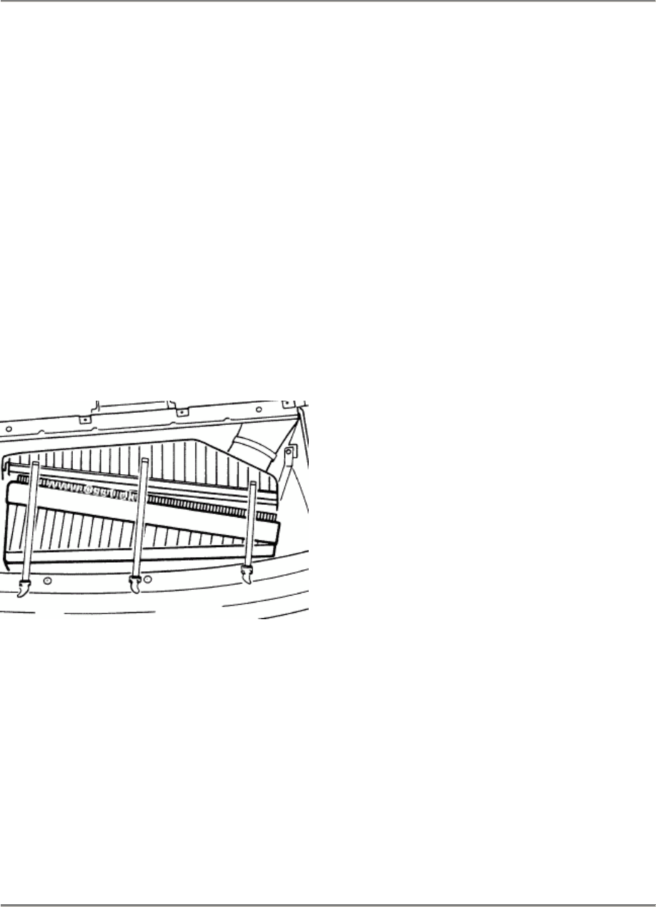
944 Air Flow Controlled Fuel Injection 24
Replacing air filter insert
Model 89 onward
Engine type M 44.41 (3.0 l)
1.
Replace front end plate. Refer to 944
Workshop Manual Page 50 - 5.
2.
Undo retaining clips and remove housing
cover with filter insert.
3.
Clean inside of filter housing with lint-free
cloth.
4.
Install new filter insert. Observe
installation
position. Arrow or TOP-OBEN marking
points towards the engine.
172 - 24
Checking idle speed and CO- with catalytic converte
Printed in Germany - XIX, 1989 24 - 107

26 944
26 - 100 Blank Page
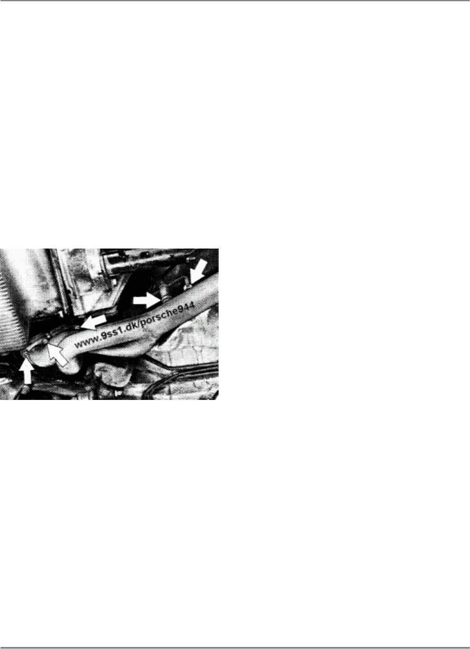
944 Exhaust System
26
CHECKING TIGHTNESS OF EXHAUST SYSTEM FLANGES (16-VALVE ENGINES)
1.
Check tightness of exhaust
flanges and check entire exhaust
system for leaks.
2. Check tightness of hex nuts on
exhaust manifold/cylinder head
flange.
3. Check tightness of all flange
connectians in exhaust system,
together with oxygen sensor and
exhaust extractian tube.
4.
Check tightness af bolts in
primary muffler (catalytic
converter)/secondary muffler
flange. Check exhaust-system
hangers.
Tightening torques of nuts and
bolts:
M 8
M10 20 + 2 Nm (14 + 1.4 ftlb)
40 + 5 Nm (30 + 3.6 ftlb)
Printed in Germany - XIII, 1987 Checking Tightness of Exhaust
System Flanges
26 - 101

28 944
28 - 100 Blank Page
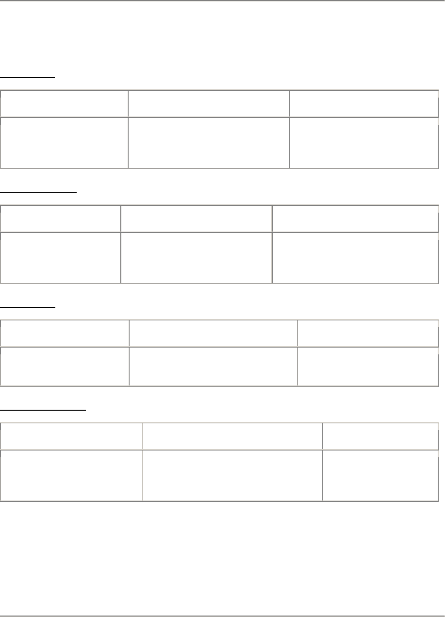
944 Ignition System
28
EQUIPMENT TABlE
Ignition Coil
Type/Model Version Remarks
944 S 944 602 115 00
Bosch No.
0 221 118 322
Without series
resistors
Distributor (Cap)
Type/Model Version Remarks
944 S 928 602 211 01
Bosch No.
1 235 522 395
Only high-tension
distribution
Spark plugs
Type/Model Version Remarks
944 S Bosch WR 7 DC Spark gap
0.7 + 0.1 mm
Ignition trigger box
Type/Model Version Remarks
944 S 928 602 706 01
Bosch No.
0 227 100 124
Printed in Germany - XIII, 1987 Equipment Table
28 - 101
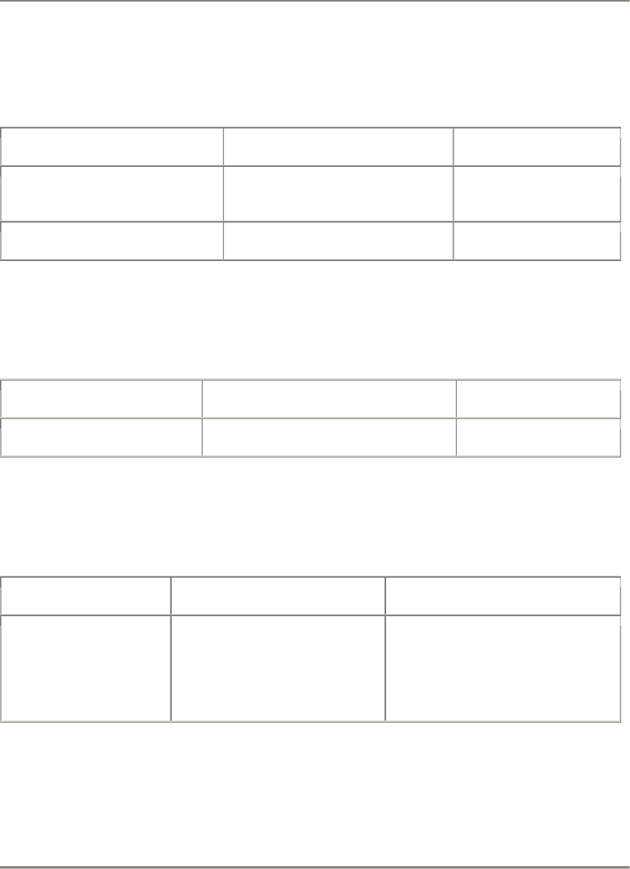
28 Ignition System 944
DME control unit
Type/Model Version Remarks
944 S Mod. '87 944.618.124.00
944.618.124.01 M 44.40
Spare part
944 S Mod. '88 944.618.124.01 M 44.40
Hall probe for knock sensors
Type/Model Version Remarks
944 S 944.606.170.01
Knock sensor
Type/Model Version Remarks
944 S 944.606.145.00 Tightening torque
= 20 Nm (14 ftlb),
use specified
mounting bolt
(without washer)
28 - 102
Printed in Germany - XXV, 1992
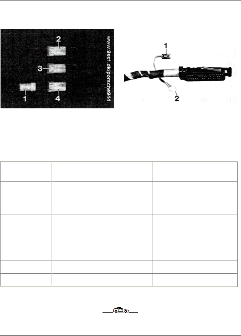
944 Egnition System
28
DME CONTROL UNIT CODING, 944 S, '87 MODELS ONWARD
1 - 944.612.525.01
2 - 928.607.421.00
3 - 928.607.422.00
4 - 944.612.522.00
1 - Plug for characteristic-map switch
2 - Plug for variant switch
Country Characteristic-map switch,
ter. 54 Varient switch, ter. 39
USA, rest of
world with
catalytic
converters
California,
Japan 928.607.421.00
EC, without
catalytic
converters
928.607.422.00
Sweden 944.612.522.00
Australia 944.612.525.01
Printed in Germany - XVII, 1988 DME Control Unit Coding,
944 S '87 Models Onward
28 - 103
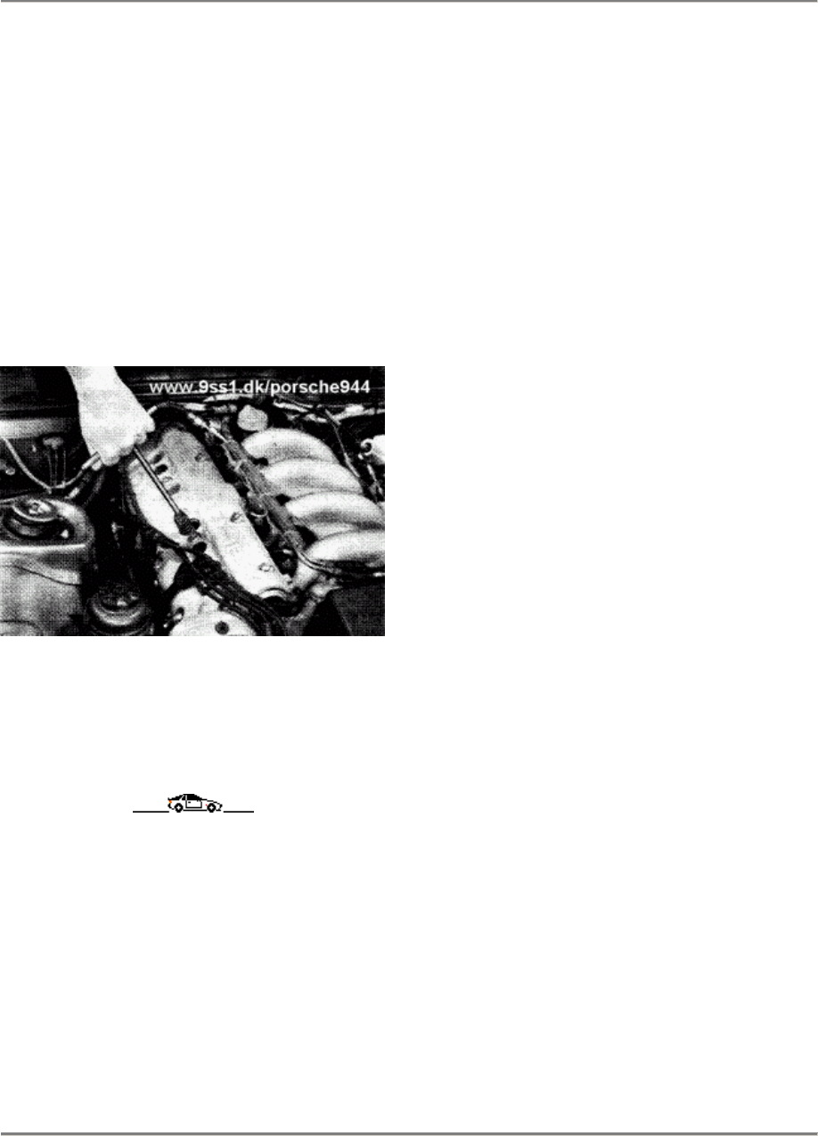
28 Ignition System 944
REPLACING SPARK PLUGS, 944 S
1.
Pull off spark plug caps.
2. Unscrew spark plugs with
commercially available wrench. A
spark-plug wrench is supplied as
part of the car's toolkit.
Tightening torque: 25 - 30 Nm
(18 - 22 ftlb).
28 - 104 Replacing Spark Plugs Printed in Germany

944 Ignition System 28
Equipment tabte 89 models onward
Engine type M 44.41 (3.0 l)
Ignition Coll
Type/Model Version Remarks
944 S 2 944 602 115 00
Bosch No.
0 221 118 322
without series resistors
Distributor (Cap)
Type/Model Version Remarks
944 S 2 928 602 211 01
Bosch No.
1 235 522 395
Only high-tension distribution
Spark plugs
Type/Model Version Remarks
944 S 2 Bosch WR 5 DC Spark gap
0,7 + 0,1 mm
Ignition trigger box
Type/Model Version Remarks
944 S 2 928 602 706 01
Bosch No.
0 227 100 124
Equipment table 89 models onward
Printed in Germany - XXV, 1992 28 - 105

28 Ignition System 944
DME Control unit
Type/Model Version Remarks
944 S 2 Mod. ´89/90
944 S 2 Mod. ´91 944.618.124.02
944.618.124.05
Hall probe for knock sensors
Type/Model Version Remarks
944 S 2 944.606.170.01
Knock sensor
Type/Model Version Remarks
944 S 2 944.606.145.00 Tightening torque
= 20 Nm (14 ftlb),
use specified
mounting bolt
(without washer)
28 - 106 Equipment table 89 models onward
Printed in Germany - XXV, 1992
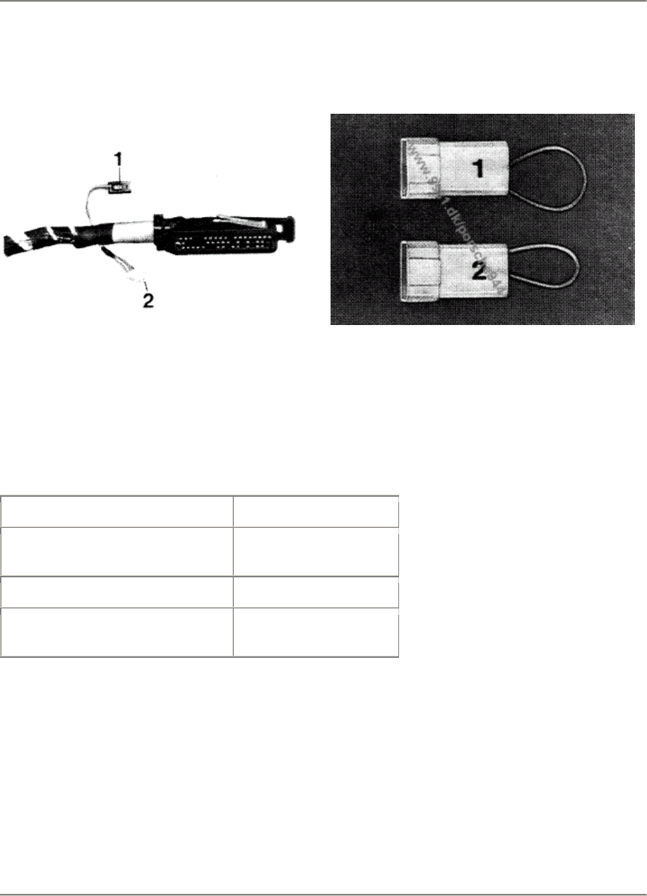
944 Ignition System, Diagnosis 28
Coding - DEE control unit 944 S 2, Model 89 onwards
86/746 B
86/733
1 - 928.607.421.00
2 - 928.607.422.00 1 - not used
2 - connector for variant switch
Country Variant switch
USA, rest of world with
catalytic convertor
California, Japan 928.607.421.00
Rest of world without
catalytic converter
928.607.422.00
Coding - DEE control unit 944 S 2, Model 89 onwards
Printed in Germany - XIX, 1989 28 - 107
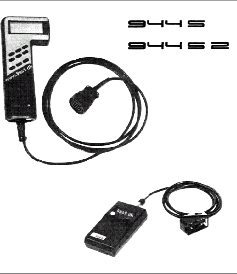
DME-Diagnosis / Troubleshooting
Dr. Ing. h.c. F. Porsche Aktiengesellschaft

944 S/944 S2 Fuel System - Electronic Control 24/28
Test Point Description Page
1
2
3
4
5
6
7
8
9
10
11
12
13
14
15
16
17
18
19
20
21
22
23
24
25
Precautions
Important Vehicle Information
Testing Requirements
Effects of Faults (Cross Reference List)
DME Control Unit Plug Connections
Power Supply
Idle Speed Contact
Full Load Contact
Engine Temperature Sensor
Air Flow Sensor
Idle Speed Control Activation
Oxygen Regulation Stop
Oxygen Sensor
Intake Air Temperature Sensor
Knock Sensor I
Knock Sensor II
Control Unit Faulty
Hall Signal
Control Unit Faulty
DME Relays
Tank Venting Valve
Check Engine Waming Lamp
Fuel Pressure
Intake System Leaks
Ground and Plug Connections
Speed/Reference Mark Sender
Ignition and Final Stage
Fuel Injectors - Injection Control Unit
Alternator / Regulator
Leads K and L
CO and Idle Speed Test
Coding of Control Unit
Check-Engine-Lamp
2
3
4
7
8
9
10
11
12
13
14
15
16
16
17
17
18
18
18
19
19
20
21
22
22
24
25
28
29
29
30
31
32
DME - Diagnosing/Troubleshooting
Printed In Germany - XXI, 1989 D 24/28 - 1

24/28 Fuel System - Electronic Control 944 S/944 S2
Precautions
Greater demands of modern engines on the ignition systems and a desire for freedom from
maintenance had led to the introduction of electronic ignition systems in standard production
some time ago already. Normally the ignition power of electronic systems (almost all makes)
will be greater than that of conventional systems and evan greater power can be expected in
the future. This places electronic ignition systems in a power range, where touching current
carrying parts or terminats could be dangerous to lite (both primary and secondary circuits).
In conjunction with this matter we must point out that there must always be conformance with
safety regulations and legislation of a pertinent country when working on or testing ignition
systems. The ignition (ignition or source of power) must always be switched off when working
on the ignition system.
Sample Jobs:
Connecting engine testers, for example:
timing light, dwell angle/speed tester, oscilloscope, etc..
Replacing ignition components, for example:
spark plugs, ignition coil, distributor, ignition leads, etc..
The above mentioned dangerous voltage will be present in the entire system should it be
necessary to switch on the ignition for ignition tests or engine adjustments.
Consequently there is not onty danger on the various components of an ignition system (such
as, for example, distributor, ignition coil, control units, ignition tackle), but also on wire
harnesses, plug connections and testers.
D 24/28 - 2 DME - Diagnosing/Troubleshooting
Printed In Germany - XXI, 1989

944 S/944 S2 Fuel System - Electronic Control 24/28
Important Vehicle Information
Always turn off the ignition or disconnect the battery for resistance tests (if not, the tester
could be destroyed).
Always disconnect the speed sender plug for compression tests (if not, there could be
dangerous high tension and damaged insulation on the ignition coil, high tension distributor
and ignition leads).
Never replace a specified ignition coil (see order number) with a different ignition coil.
Never connect a suppression capacitor on ignition coil terminals 1 and 15.
Never connect ignition coil terminal 1 on ground for the burglar alarm (ignition coil and
control unit could be destroyed).
Never connect battery + or a test lamp on ignition coil terminal 1 (control unit could be
destroyed).
Never disconnect the ignition lead between ignition coil terminal 4 and high tension
distributor terminal 4 during operation.
Avoid voltage flashover from ignition coil terminal 4 to ignition coil terminals 1 and 15
(control unit could be destroyed).
To avoid destruction of the control unit, the secondary circuit of the ignition system must be
suppressed with at least 4 k-ohms, whereby the original distributor rotor with 1 k-ohm
suppression resistance must be installed.
Disconnect DME control unit and ignition final stage plugs only atter turning off the ignition.
Flashover or disruptive discharge in the area of the high tension distributor cap (poor
insulation) could destroy the control unit.
Never disconnect the battery while the engine is running.
Mixing up battery pole connections could lead to destruction of the ignition final stage,
ignition coil and DME control unit.
Outside starting of the engine with more than 16 volts or a boost battery charger is
forbidden.
Always conform with accident prevention regulations when working on fuel systems.
DME - Diagnosing/Troubleshooting
Printed In Germany - XXI, 1989 D 24/28 - 3

24/28 Fuel System - Electronic Control 944 S/944 S2
Equipnient Required for DME Tests:
-
Diagnostics tester 9288 (9268) with
connecting leads
-
1 oscilloscope approved by Porsche
-
1 digital display multimeter with an internal
resistance of at least 10 M-ohms
-
1 Bosch L-Jetronic test lead, Bosch No.
1684 463 093 (check read for correct
polarity in plugs)
-
2 control unit plug test leads (local
manufacture) fitted with 2 flat male plugs,
'N 17.457.2, in order to avoid damage on
plug pins in the control unit plug while
testing
-
2 adapter test leads, consisting of 4 plug
connectors, N 017.483.1, soldered with 2
approx. 150 mm lang leads
-
1 three-pin test lead (e.g. VW VAG 1501)
-
2 control unit plug test leads (local
manufacture) fitted with 4 flat male plugs,
N 17.457.2
Test leads must always be used for
testing!
-
All sender and ignition timing signals of
Porsche models can be checked with the
engine reglers recommended by Porsche.
Instructions for connection of testers on a
car will be different depending on the
make, so that it will always be necessary
to conform with the instructions supplied
with a pertinent tester.
Sender Signals Which Can Be Checked
With An Oscilloscope:
-
Speed sender signal
-
Injection ( ) signals
-
Idle speed control activation signal
-
Hall sender signal
-
Ignition trigger signal to ignition final stage
-
Tank venting activation signal
as well as:
-
Reed switch signal (speedometer)
-
ABS wheel sensor signals
D 24/28 - 4 DME - Diagnosing/Troubleshooting
Printed In Germany - XXI, 1989

944 S/944 S2 Fuel System - Electronic Control 24/28
Diagnosable DME Control Unit
Self-
diagnosis with a fault memory, with which it is possible to detect and store certain injection.
ignition and knock regulating system faults, is integrated in the DME control unit of 944 S cars
beginning with 1988 models.
The DME control unit has a permanent positive connection to prevent cancellation of detected
and stored faults by turning off the ignition. Detected faults remain stored in the memory for at
least 50 engine starts (exception: idle speed switch interruption faults).
Important!
If the DME control unit plug or battery is disconnected, the fault memory and system adaptation
will be cancelled.
Tester Connections:
A 12-pin plug, which leads out of the DME wire harness in the passenger's footwell to the right
above the DME control unit, is provided for diagnosing in cars since 1988 models. 9268
Flashing Code Testers can be connected on this plug.
A 19-pin plug replaces the 12-pin plug beginning with 1990 (L) models. Either a 9288 System
Tester or the Flashing Code Tester (via adapter leads 9268/2) can be connected on this plug.
Operation of the testers is explained in the instructions supplied with the testers.
Note:
A pertinent test point is supplemented by a corresponding fault flashing code of Tester 9268.
Example:
Test Point 2 = idle speed contact (1-12)
Second digit display:
"1" fault exists
"2" fault does not exist
The following actual engine data can be read direct in the "actual value" menu with a 9288
System Tester beginning with the version 2.0 tester module status.
Intake air temperature
Ignition timing
Oxygen sensor voltage
Version code
Idle drive pulse duty factor
Engine temperature
Engine speed
Power supply
Air flow sensor signal
Load signal
DME - Diagnosing/Troubleshooting
Printed In Germany - XXI, 1989 D 24/28 - 5

24/28 Fuel System - Electronic Control 944 S/944 S2
This DME 944 S Diagnosing/Troubleshooting Plan is based on the contents of the fault
memory.
Paths not included in self-diagnosis can be diagnosed with conventional equipment (Test
Points 17-25. see Fault List).
Troubleshooting requires that the person performing the tests
is familiar with the location of components, the function and technical interconnections of the
systems being tested (model information).
can read and evaluate Porsche wiring diagrams.
knows the functions of circuits and relays, and
is capable of using testers, such as the oscilloscpe, voltmeter, ohmmeter and ammeter, as
well as evaluating the test results.
Important!
A fault text in the display (Fault List and Flashing Code) does not always indicate a fault in the
pertinent component, but could also concern t
he corresponding control unit or connecting leads
(paths) between the component and control unit.
Troubleshooting on a running engine in the form of disconnection of plugs, etc. must not be
carried out prior to reading the fault memory, since such action could be stored as faults in the
fault memory.
9288 System Tester Information
Displayed in Tester
Fault does not exist, this could mean:
Fault not existing at time of testing (loose contact).
Remedy: visual inspection of path (connection).
Conditions, with which the fault is tested. ara not the same as the conditions, with which the
fault had occurred.
Remedy: conform with conditions displayed in the tester.
Signal Not Plausible:
Signal of the monitored component does not fit in the tolerance range of the value calculated in
the control unit.
D 24/28 - 6 DME - Diagnosing/Troubleshooting
Printed In Germany - XXI, 1989

944 S/944 S2 Fuel System - Electronic Control 24/28
This page are missing or blank in the book !
DME - Diagnosing/Troubleshooting
Printed In Germany - XXI, 1989 D 24/28 - 7

24/28 Fuel System - Electronic Control 944 S/944 S2
This page are missing or blank in the book !
D 24/28 - 8 DME - Diagnosing/Troubleshooting
Printed In Germany - XXI, 1989
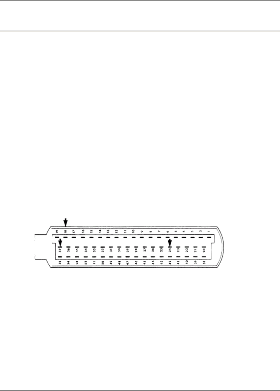
944 S/944 S2 Fuel System - Electronic Control 24/28
Fault, Fault Code Possible Causes, Elimination, Remarks
Test
Point
1a
Power
supply for
DME
control unit
(V)
a) Perm. pos. (B + )
Fault memory is cancelled, if there is
no B +.
Testing:
Connect a voltmeter on terminal 24 (-) and terminal 18 ( +) of the control unit plug
with help of test leads.
Display: battery voltage
No display: check current flow and ground paths according to the wiring diagram.
Test Point
1b
Power
supply for
DME
control unit
(V)
too high /
too low
Fault Code
1_11
b) Power supply via DME relay
Connect a voltmeter on terminal 24 (-) and terminal 37 (+) of the control unit plug
with help of test leads. Turn on ignition.
Display: battery voltage
No display: check current flow path according to the wiring diagram.
Remarks:
Cars with burglar alarm: check power supply from ignition lock via burglar alarm
control unit to terminal 86 af the DME relay according to the wiring diagram.
Cars without burglar alarm: check pin bridges on plug (provided for installation
of a burglar alarm control unit).
DME - Diagnosing/Troubleshooting
Printed In Germany - XXI, 1989 D 24/28 - 9
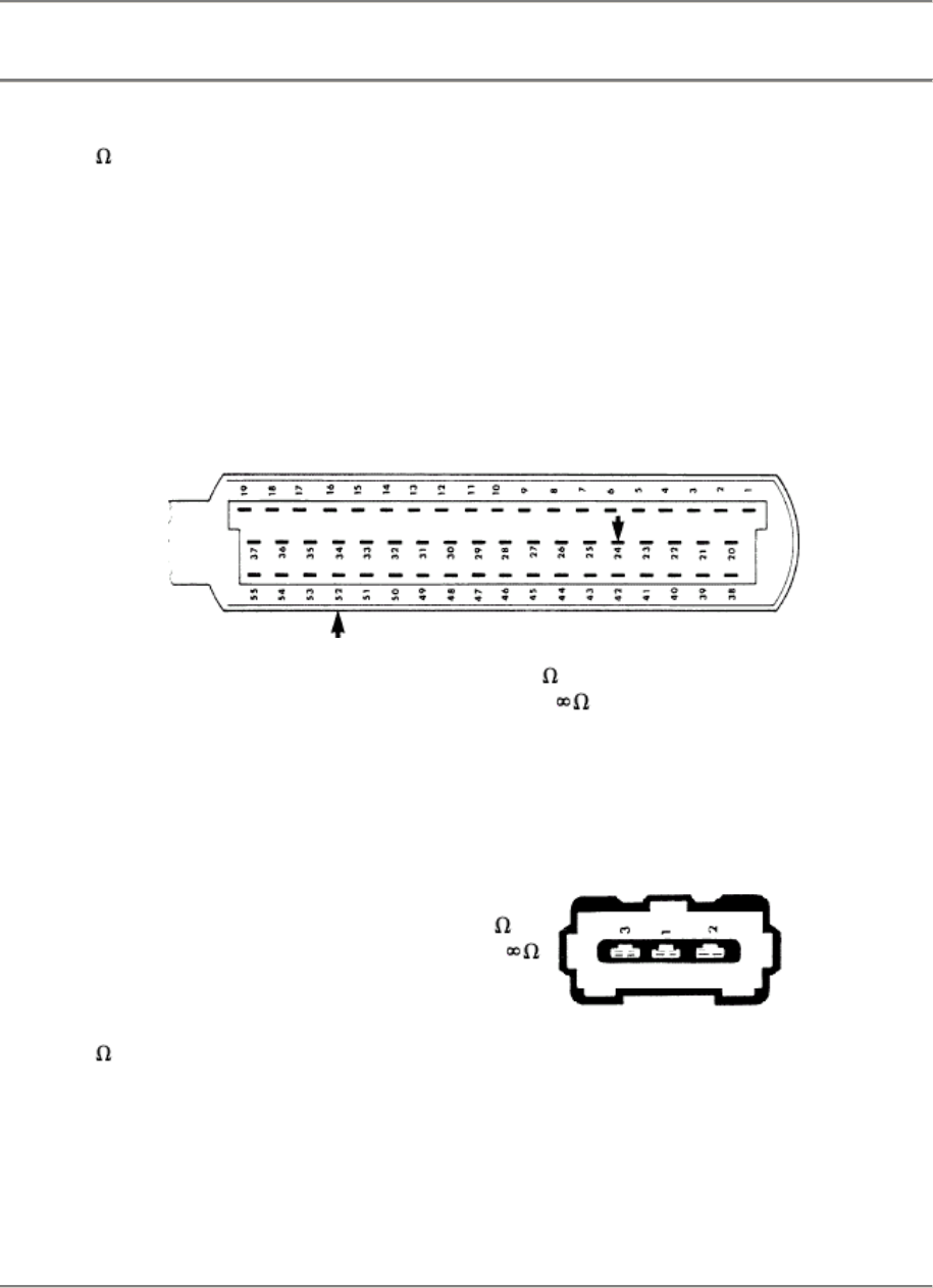
24/28 Fuel System - Electronic Control 944 S/944 S2
Fault, Fault Code Possible Causes, Elimination, Remarks
Test Point 2:
Idle speed
contact ( )
Ground short
Fault Code 1_12
Check via circuit input test with 9288 System Tester or 9268 Tester.
Select test step and operate accelerator pedal.
9288 Display:
Idle speed contact made
Idle speed contact broken
9268 Display: 1332 (idle speed contact made)
0000 (idle speed contact broken)
No Display:
Pull off plug on DME control unit.
Connect ohmmeter between terminal 52 and terminal 24 with help of test
leads.
Display:
Throttle valve closed
Throttle valve opened to gap of
< 10
> 1° =
If the value of the idle speed contact is not reached in this test, the test
should be repeated direct on the throttle valve switch as described below.
Pull off plug on throttle valve switch. Connect ohmmeter between terminals 1
and 2 of the throttle valve switch with help of test leads.
Display:
Throttle valve closed
Throttle valve opened to gap of
< 10
> 1° =
Idle speed
contact ( )
Break
Fault Code 1_15
Testing same as described for ground short
(fault stored in memory as of 1991 models).
Check for correct adjustment, correcting if necessary.
Cause, for example, could be an incorrectly adjusted throttle valve switch or
accelerator cable.
D 24/28 - 10 DME - Diagnosing/Troubleshooting
Printed In Germany - XXI, 1989
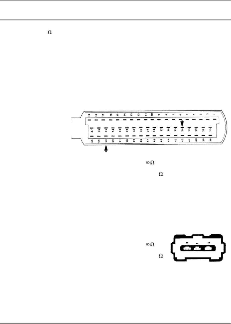
944 S/944 S2 Fuel System - Electronic Control 24/28
Fault, Fault Code Possible Causes, Elimination, Remarks
Test Point 3
Full load contact ( )
Ground short
Fault Code 1_13
Check via circuit input test with a 9288 System Tester or 9268
Tester.
Select test step and operate accelerator pedal.
9288 Display:
9268 Display:
Full load contact broken
Full load contact made
1333 (tull load contact broken)
0000 (full load contact made)
No Display:
Connect ohmmeter on terminal 53 and terminal 24 of the
disconnected DME control unit plug with help of test leads.
Display:
Throttle valve closed
Throttle valve opened about
2/3rd of full gap
< 10
If the value of the full load contact is not reached in this test, the
test should be repeated direct on the throttle valve switch as
described below.
Pull off plug on throttle valve switch. Connect ohmmeter
between terminal 3 and terminal 2 of the throttle valve switch
with help of test leads.
Display:
Throttle valve closed
Throttle valve opened about
2/3rd af full gap
< 10
Remarks:
If the full load contact fails, the control unit produces a load
threshhold via the air flow sensor. Value below this load
threshold same as switch broken or above load threshold same
as switch made.
DME - Diagnosing/Troubleshooting
Printed In Germany - XXI, 1989 D 24/28 - 11
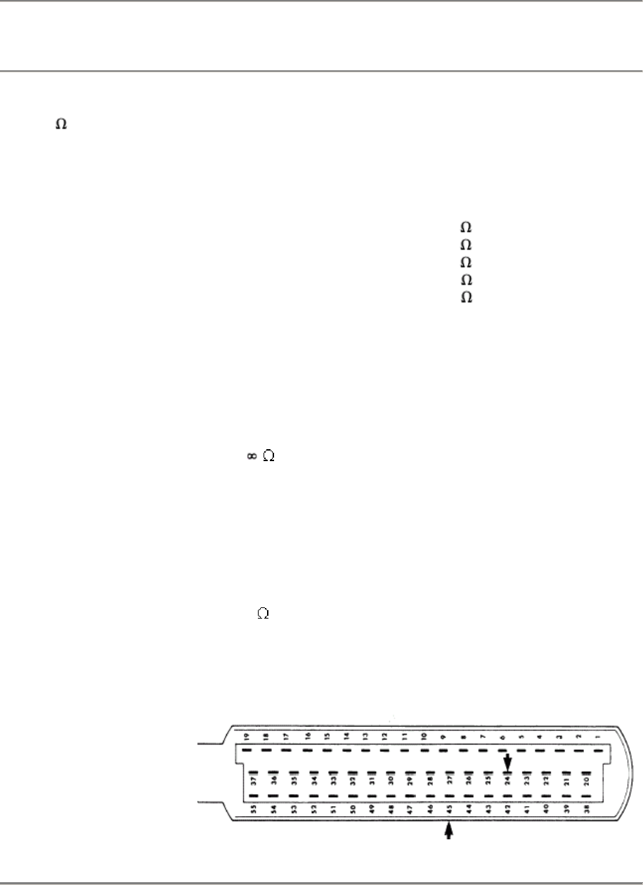
24/28 Fuel System - Electronic Control 944 S/944 S2
Fault, Fault Code Possible Causes, Elimination, Remarks
Test Point 4
Engine tamp. sensor
(NTC II/ )
Fault Code 1_14
Engine temperature can be read direct from the "actual value"
menu with a 9288 System Tester.
No Plausible Display:
Connect ohmmeter on terminal 45 and terminal 24 of the
disconnected DME control unit plug with help af test leads.
Display at:
0°C =
15 - 30°C =
40°C =
80°C =
100°C =
4.4 - 6.8 k
1.4 - 3.6 k
1.0 - 1.3 k
250 - 390
160 - 210
Test direct on the engine temperature sensor, if the values are
not reached.
Note: Temperature sensor II sends information about the engine
temperature to the control unit. It is used to provide a rich fuer/air
mix-ture after a cold start or during warm-up.
Break ( ):
DME control unit of the 944 S selects a resistance value, which
is stored in the control unit's memory and is approximately equal
to that of an engine at operating temperature. There is no
enrichment from a faulty NTC II when the engine is warm
(emergency running program). This results in starting problems
when the engine is cold (no cold start enrichment).
Short (0 ):
No engine pickup, too lean and stopping of engine in cold state.
No effects in operating temperature state.
Replacement value is applicable to both types of fault!
D 24/28 - 12 DME - Diagnosing/Troubleshooting
Printed In Germany - XXI, 1989
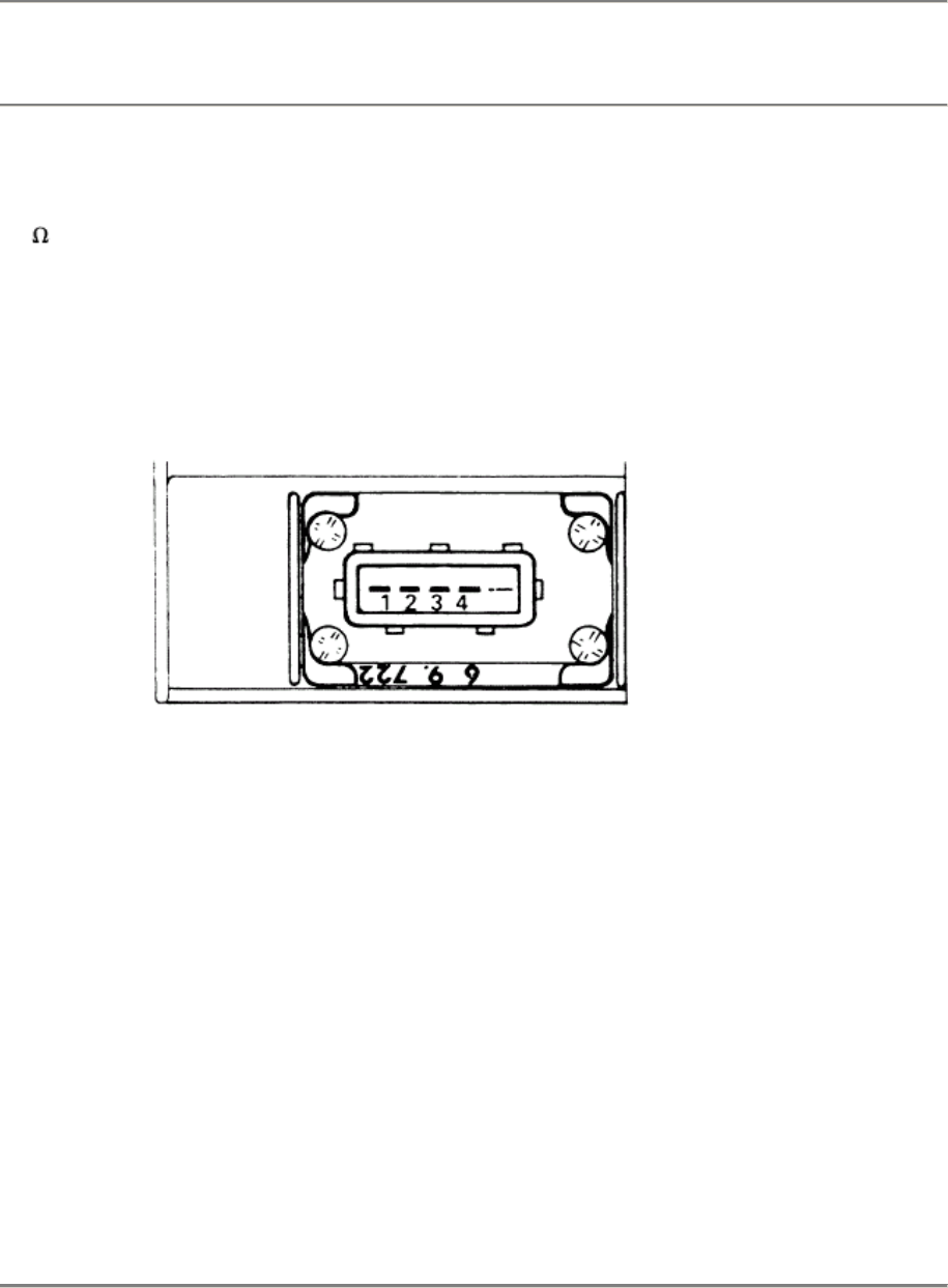
944 S/944 S2 Fuel System - Electronic Control 24/28
Fault, Fault Code Possible Causes, Elimination, Remarks
Test
Point 5a:
Air flow
sensor
(V/ )
Fault
Code
1_21
The ratio between Up (potentiometer voltage) and Uv (power supply voltage) can
be read in the "actual value" menu with a 9288 System Tester.
When opening the air flow sensor plate the ratio must be about 0.0 to 1. If not:
a) Power supply voltage
Connect a voltmeter on terminal 3 and terminal 4 of the disconnected air flow
sensor plug with help of test leads. Turn on ignition.
Display: 5 +- 0.3 volts
Test
Point
5b:
b) Voltage drop on air flow sensor plate potentiometer (V)
Take off air cleaner connecting hose. Connect pin 3 of the disconnected air flow
sensor plug with air flow sensor plug terminal 3 and pin 4 with air flow sensor plug
terminal 4 with help of test leads.
Connect a voltmeter on air flow sensor terminal 2 and terminal 4 (turn on ignition).
Display: approx. 250 - 260 m V
It must be possible to move the air flow sensor plate easily and without hesitation.
Observe the voltmeter's display at the same time. Voltage jump of voltage drop
should not be observed while the air flow sensor plate is opening or closing.
Display with air flow sensor prate in full load position:
approx. 4.60 volts.
DME - Diagnosing/Troubleshooting
Printed In Germany - XXIV, 1991 D 24/28 - 13
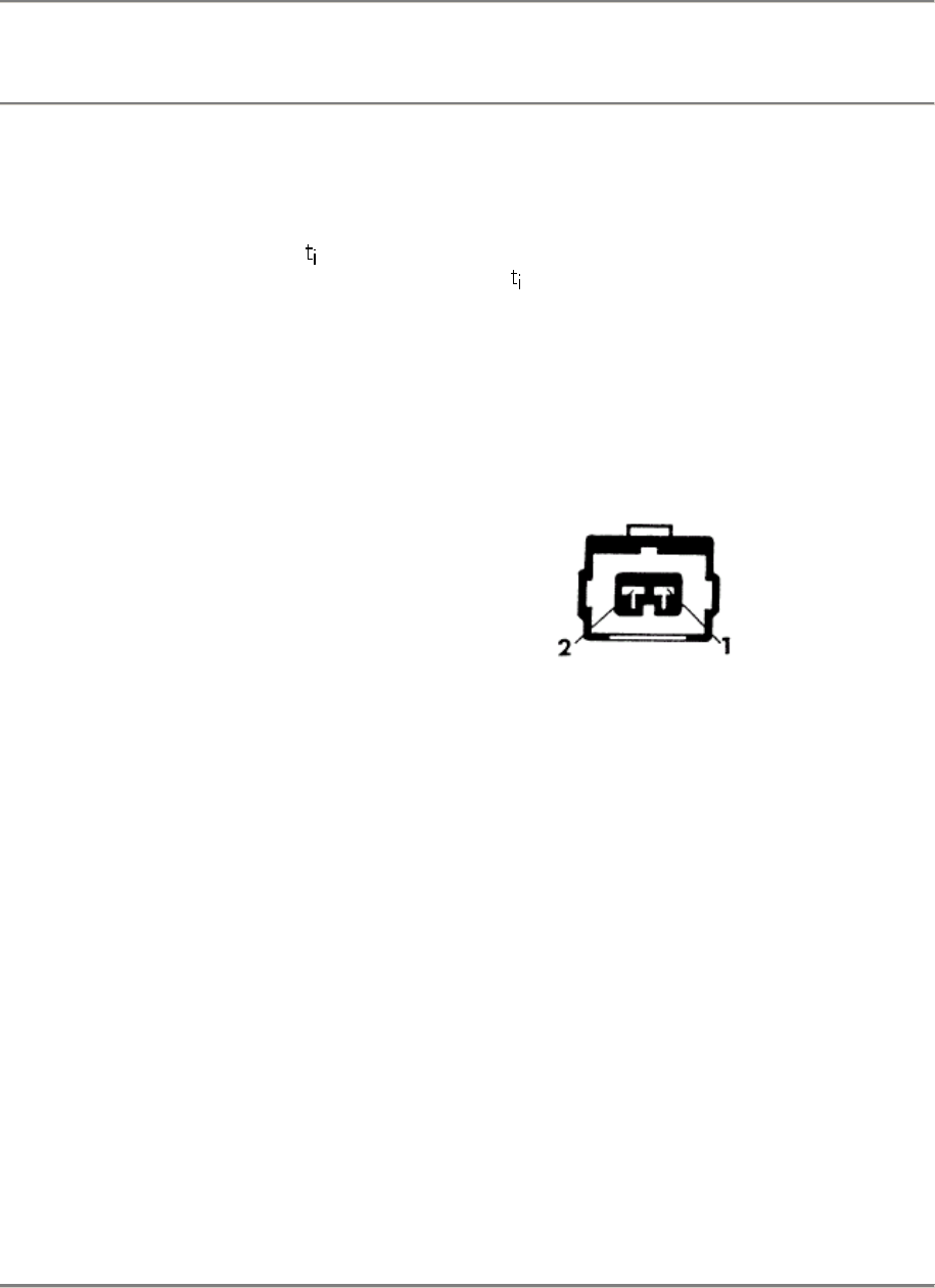
24/28 Fuel System - Electronic Control 944 S/944 S2
Fault, Fault Code Possible Causes, Elimination, Remarks
Turn off ignition and reconnect plug if the voltage values have been reached.
Remarks:
Control unit produces replacement values in case of air flow sensor failure
(emergency running program).
Injection signal
from nominal air of the idle speed volumetric efficiency control
for idle or a constant injection signal for partial load and full load ranges.
Test Point 6:
Idle speed
control (V)
Fault Code
1_22 only S2
Element Activation Menu
If pulse cannot be heard, check:
Power supply
Connect a voltmeter on terminal 2 and
ground of the disconnected idle speed
control plug.
Turn on ignition.
Display: battery voltage
No display:
Check power supply according to the wiring diagram.
Control signal test
The pulse duty factor in % can be read direct in the "actual value" menu with a
9288 System Tester.
Function test: Switch on electric power consumers with engine running at idle
speed. The pulse duty factor must change and the idle speed must remain
constant.
If not:
D 24/28 - 14 DME - Diagnosing/Troubleshooting
Printed In Germany - XXI, 1989
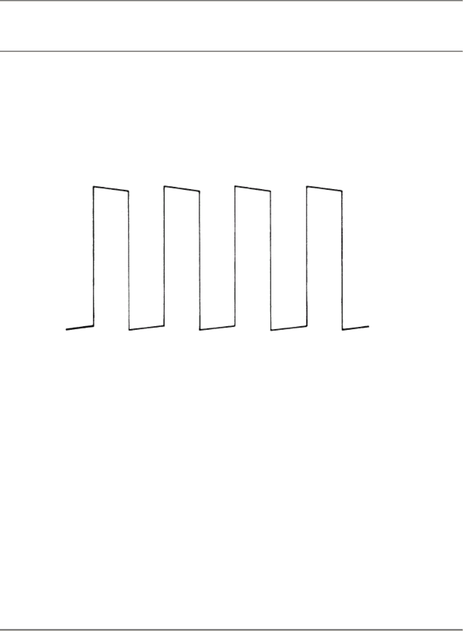
944 S/944 S2 Fuel System - Electronic Control 24/28
Fault, Fault Code Possible Causes, Elimination, Remarks
Connect two-pin DME test lead (Bosch No. 1 684 463 093) between the speed
control and plug.
Connect and adjust engine tester to supplied operating instructions.
Make sure that electric lead connections do not have contact with vehicle ground
(danger of short).
Displayed with the engine running:
Frequency: approx. 100 Hz.
Replace the idle speed control it the pulse cannot be heard in spite of correct
power supply and received signal.
Test Point
7
Oxygen
regulation
on stop
Fault Code
1_23
Oxygen regulation cannot work in its regulating range in case at disturbances in
air/fuel mixture; for example: too lean because of excessive air or too rich
because of a sticking fuel injector. It then moves against the stop.
Test 1:
Check CO level with the engine running and CO
tester connected (between 0.4 and 1.2 %).
too lean:
Check intake system for leaks
(Test Point 19).
too rich:
Check system pressure (Test Point 18).
Check fuel injectors for leaks (Test Point 18).
DME - Diagnosing/Troubleshooting
Printed In Germany - XXI, 1989 D 24/28 - 15
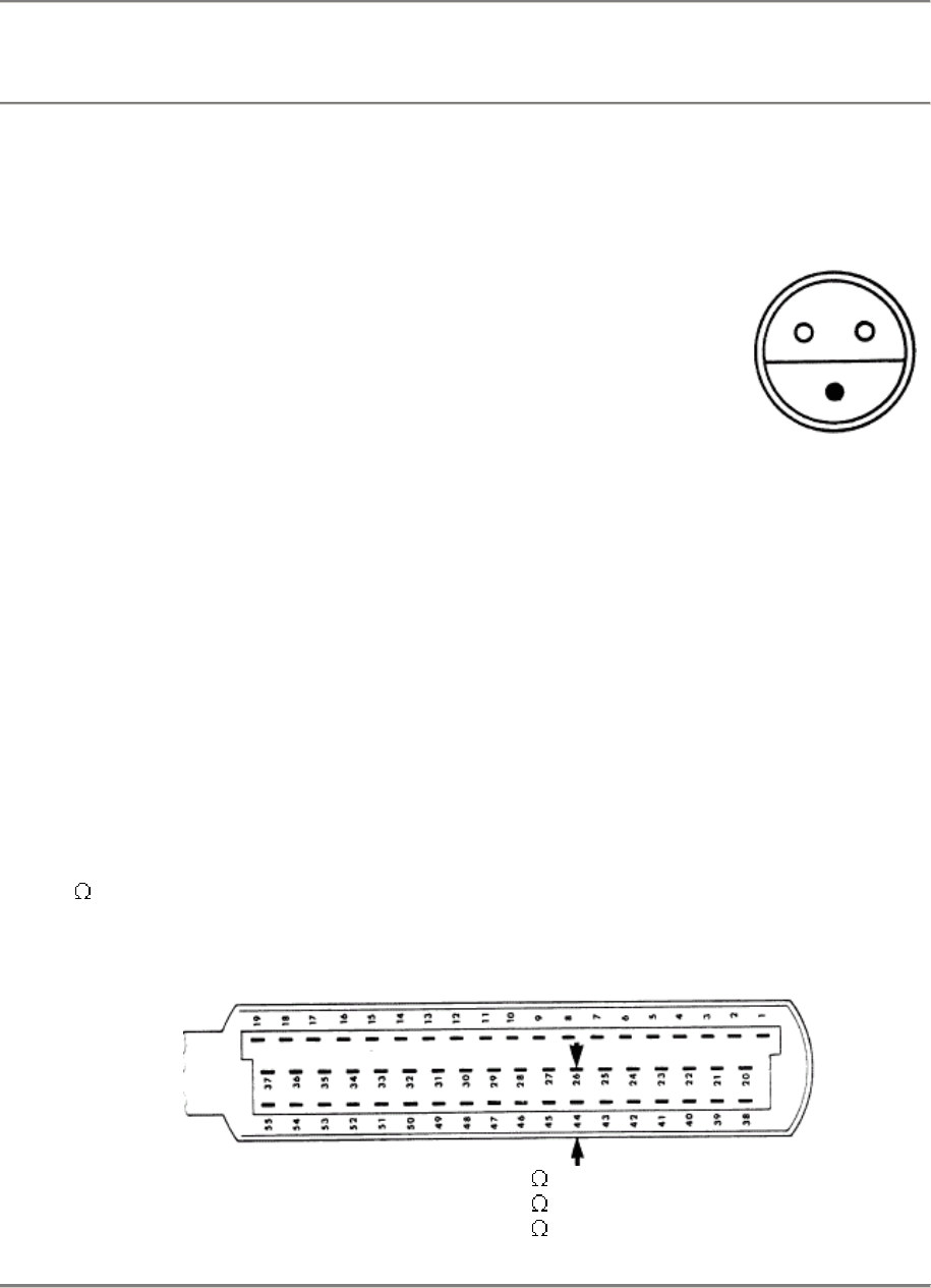
24/28 Fuel System - Electronic Control 944 S/944 S2
Fault, Fault Code Possible Causes, Elimination, Remarks
Test Point 8:
Oxygen sensor
(V)
(sensor signal)
Fault Code 1_24
Sensor signal test
Sensor voltage can be read direct in the "actual value" menu with a 9288
System Tester.
If not:
Disconnect oxygen sensor plug. Connect a digital display
voltmeter on the sensor end test connection (sensor
voltage signal) and ground.
Start and run engine warm so that the oxygen sensor
reaches its operating temperature. A change in the
voltage signal must be displayed when the mixture is
richer, e.g. by accelerating.
Display on voltmeter:
approx. 150 mV - 900 mV (depending on composition of mixture)
Remarks:
If the control unit recognizes an oxygen) sensor voltage signal of more than
1 V or less than 0.1 V, the control unit will switch over to operation without
oxygen sensor (short or break).
If regulation does not work and the sensor voltage signal is okay, check the
coding of the control unit before replacing the control unit.
Test Point 9
Air temperature
sensor
NTC I ( )
Fault Code 1_25
Intake air temperature can be read direct in the "actual value" menu with a
9288 System Tester.
If not or when a non-plausible value is displayed:
Connect an ohmmeter on terminal 44 and terminal 26 of the disconnected
DME control unit plug.
Display at:
0°C =
15-30°C =
40°C =
4.4-6.8 k
1.4-3.6 k
1-1.3 k
D 24/28 - 16 DME - Diagnosing/Troubleshooting
Printed In Germany - XXI, 1989
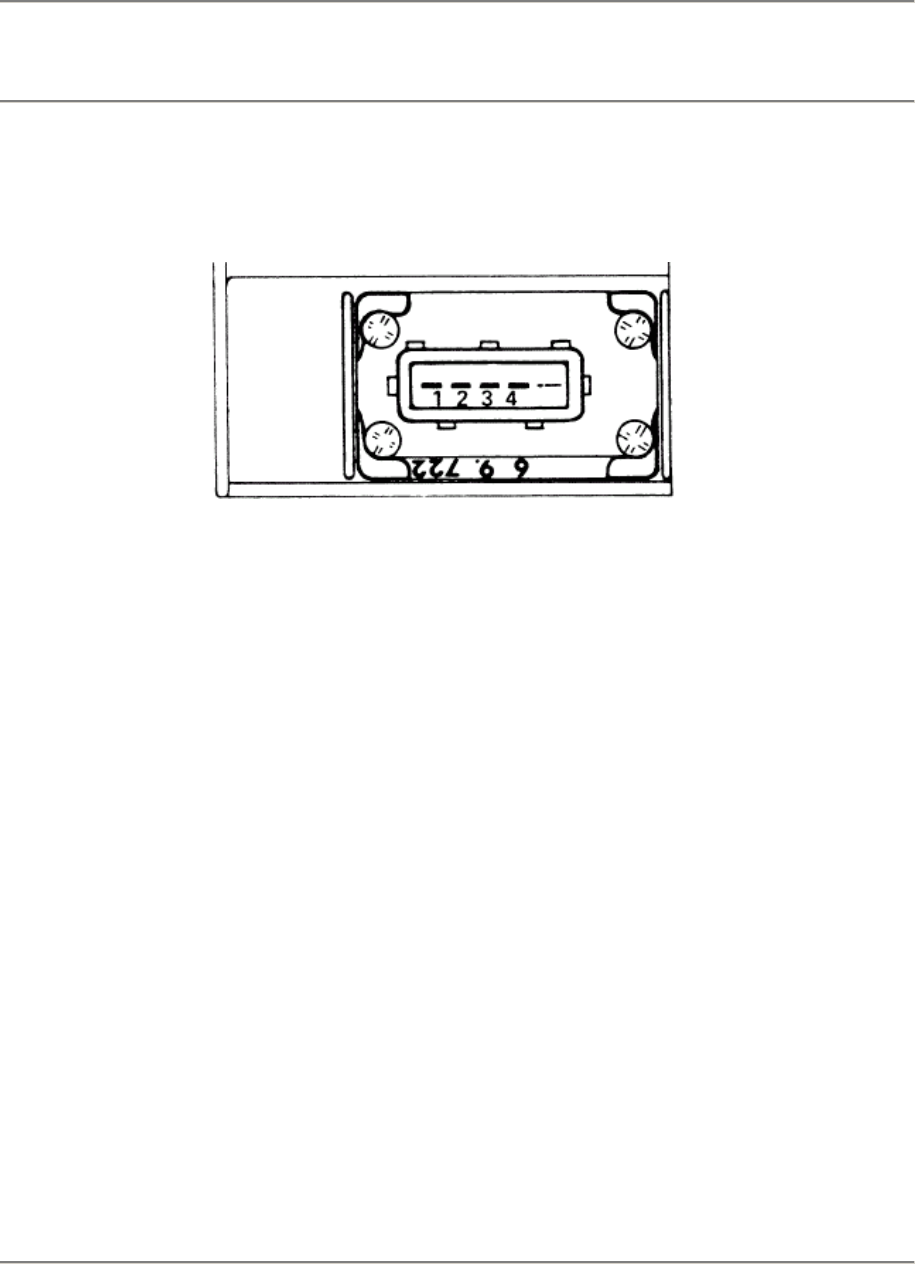
944 S/944 S2 Fuel System - Electronic Control 24/28
Fault, Fault Code Possible Causes, Elimination, Remarks
If no display: Disconnect plug on air flow sensor. Connect an ohmmeter on air
flow sensor terminals 1 and 4 with help of test leads. Display: same as above.
Note: In case of a break, there will be a replacement value equal to an intake
air temperature of 20° C (emergency running program).
Test Point 10
Knock sensor
I
Fault Code
1_31
Knock sensor I: Knock signal not plausible. Check:
-
-
-
-
Installation of knock sensor (check tightening torque and type of screw).
Wire harness and plug connections according to wiring diagram.
Reconnecting sensors eliminates contact resistance.
Whether coolant or other liquids are in area of the knock sensor.
Replace knock sensor.
Ignition timing retarded by 6° on crankshaft in case of a faulty knock sensor.
Test Point 11
Knock sensor
II
Fault Code
1_32
Knock sensor II: Knock signal not plausible. Check:
-
-
-
-
Installation of knock sensor (check tightening torque and type of screw).
Wire harness and plug connections according to wiring diagram.
Reconnecting sensors eliminates contact resistance.
Whether coolant or other liquids are in area of the knock sensor.
Replace knock sensor.
Ignition timing retarded by 6" on crankshaft in case of a faulty knock sensor.
DME - Diagnosing/Troubleshooting
Printed In Germany - XXI, 1989 D 24/28 - 17
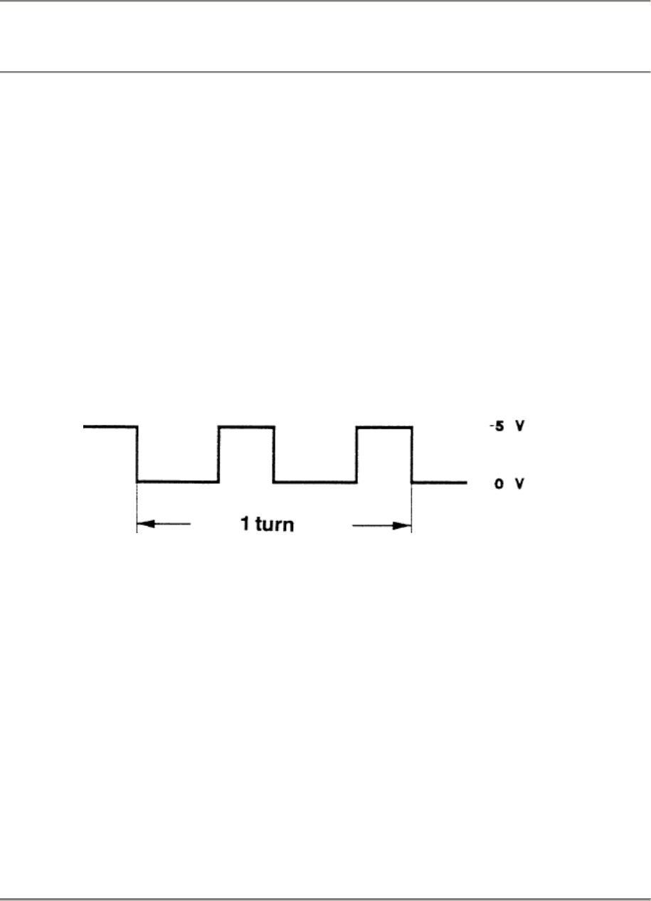
24/28 Fuel System - Electronic Control 944 S/944 S2
Fault, Fault Code Possible Causes, Elimination, Remarks
Test Point
12:
Control
unit
(knock
computer)
Fault Code
1_33
Ignition timing is retarded 6° in case of this fault.
Replace control unit.
Test Point
13:
Hall signal
Fault Code
1_34
Disconnect plug on cylinder head behind the camshaft drive gear and connect a
three-pin adapter lead (VW 1501) inbetween to check the Hall signal. Connect
oscilloscope positive and negative test leads on terminals 1 and 2 of the adapter
lead. Start the engine.
This signal should be displayed when the Hall system is okay:
Ignition timing will be retarded approximately 6° in all speed ranges, if the DME
control unit recognizes that the Hall signal is missing.
Protective circuit test:
Turn off ignition. Disconnect Hall plug. Start the engine. Idle speed ignition timing
will adjust itself to approximately 4° before TDC (944 S). There must be a certain
load signal from the air flow sensor in case of 944 S2 cars.
Test Point
14:
Control
unit faulty
Fault Code
1_41
Replace control unit.
D 24/28 - 18 DME - Diagnosing/Troubleshooting
Printed In Germany - XXI, 1989
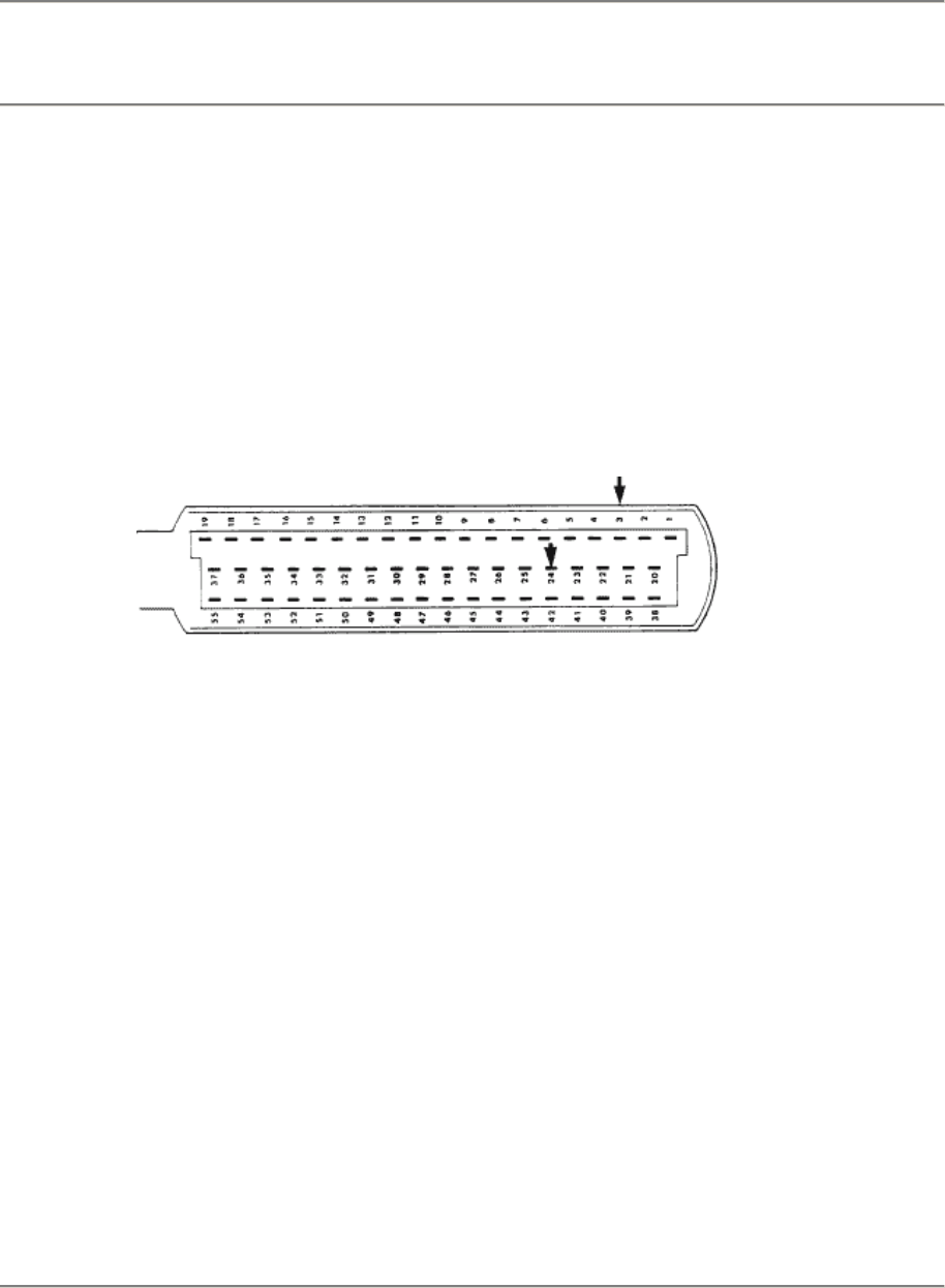
944 S/944 S2 Fuel System - Electronic Control 24/28
Fault, Fault Code Possible Causes, Elimination, Remarks
Test
Point 15:
DME
relay
(fuel
pump) (V)
Start the engine - fuel pump must run during engine starting.
It not:
Turn off ignition. Disconnect control unit plug. Connect terminal 3 and terminal 24
on the control unit plug with help of a test lead.
Turn on ignition - the pump must run!
It not:
Check current flow and ground paths of DME relay and fuel pump according to the
wiring diagram.
Test
Point 16:
Tank
venting
valve (V)
Fault
Code
1_43
(not 944
S)
Electric valve (for brake booster) will be opened more or less long depending on
the engine load when an engine having operating temperature is running. The
opened time is determined by a ground pulse from the control unit.
a) Activation test
Activate the tank venting valve in the "element activation" menu of the tester. It a
pulse is not heard, check power supply to terminal 1 of the electromagnetic valve
plug according to the wiring diagram.
b) Control signal test
Install DME test read (Bosch No. 1 684 463 093) between the electromagnetic
valve and plug connection. Connect and adjust engine tester according to the
supplied operating instructions.
DME - Diagnosing/Troubleshooting
Printed In Germany - XXI, 1989 D 24/28 - 19
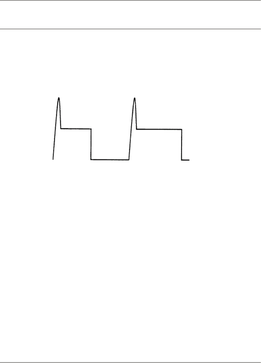
24/28 Fuel System - Electronic Control 944 S/944 S2
Fault, Fault Code Possible Causes, Elimination, Remarks
Tank venting valve is not activated permanently.
Test must be performed within 7 minutes after starting an engine having
operating temperature (interrupt tank venting valve activation approx. 75
seconds afterward and then continue).
Start engine and accelerate. This must be displayed in the tester for an engine
at operating temperature:
Signal will be wider as the air flow rate increases!
Check path according to the wiring diagram if there is no signal.
Replace control unit if necessary.
Test Point
17:
Check
Engine
warning
lamp
Fault Code
1_45
(California as
of
1991 models)
A ground signal from control unit plug terminal 22 goes to and switches on the
"Check Engine Lamp", if a component influencing emission control fails.
If the "Check Engine" warning lamp fails, this fault is stored in the fault
memory.
Check by supplying ground to control unit plug terminal 22 and turning on the
ignition.
Always replace a faulty display lamp with a specified lamp.
D 24/28 - 20 DME - Diagnosing/Troubleshooting
Printed In Germany - XXI, 1989
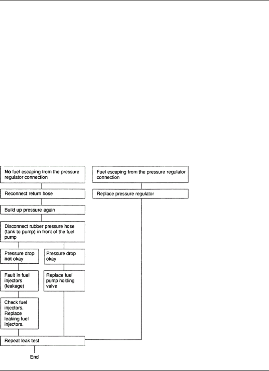
944 S/944 S2 Fuel System - Electronic Control 24/28
Test Point 18: Fuel Pressure
Fuel collection pipe has a test
connection at left front. Unscrew
cap nut of the test connection.
Important! Inserted ball seal could
fall out!
Connect P 378 pressure tester on
the test connection. Start the
engine. Vacuum on pressure
regulator at idle speed:
Test pressure: 3.3 +- 0.2. bar
Hot starting problems:
Check with the engine stopped and fuel pump
running, without vacuum on the pressure regulator
(this requires removing the DME relay and bridging
terminals 87b and 30):
Test pressure: 3.8 +- 0.2 bar
-
Stop fuel pump. Read pressure on the pres
sure tester (specitication: 3.8 +- 0.2 bar).
- Max. permissible pressure drop on warm
engine: 0.5 bar in 30 minutes.
- It the pressure drops below the specitied
value, proceed as described below.
Build up pressure again by switching on the fuel pump briefly. Remove return pipe on the
pressure regulator (fuel pump must not be switched on).
DME - Diagnosing/Troubleshooting
Printed In Germany - XXI, 1989 D 24/28 - 21

24/28 Fuel System - Electronic Control 944 S/944 S2
Test Point 19: Intake System leaks
Check all connections after the air flow
sensor for leaks. Remove upper air cleaner
section. Apply Special Tool 9264/4 on the air
flow sensor and produce approx. 0.5 bar
pressure in the intake system. Leaks will
cause the pressure in the system to drop
quickly.
(944 S: shut the safety pressure valve for
crankcase breathing.)
Remarks:
Flashing Fault Code 1_23 (oxygen
regulation on stop) is displayed in cars with
oxygen regulation and very large leakage in
the intake system (for example: intake pipe
gasket).
Test Point 20: Ground Connections (V)
Ground read (2 x) from wire harness to
engine block.
battery ground lead on clutch bell
housing (engine ground) and on body
(body ground next to battery).
Ignition final stage ground on side
member at left front.
Fuel pump ground on rear lock cross
wall behind the spare wheel.
Are ground connections tight and without
corrosion? Loosen, clean and retighten
ground connections as specified.
Caution!
Never start the engine as long as the
ground lead between the body and
engine is disconnected!
This would destroy the control unit
immediately!.
D 24/28 - 22 DME - Diagnosing/Troubleshooting
Printed In Germany - XXI, 1989

944 S/944 S2 Fuel System - Electronic Control 24/28
Plug Connections
Are all plugs connected correctly, not loose
and not corroded?
Disconnect plugs and check whether pins
and terminals of plugs are bent or corroded.
55-pin plug an DME control unit (behind
floor plate in the front passenger's
footwell).
14-pin plug in engine compartment next
to the brake booster.
3-pin plug for reference mark/speed
sender and 3-pin plug for oxygen sensor
behind the intake pipe for cylinder no. 4
(first remove cover an the fuel ring-pipe).
3-pin plug an throttle valve switch.
2-pin plug on electromagnetic valve for
tank venting (an brake boaster).
4-pin plug an air flow sensor.
2-
pin plug an NTC II (temperature sensor
is screwed in the engine block above the
left compensating shaft near cylinder no.
1).
7-pin plug on ignition final stage in the
engine compartment at front left.
3-pin Hall sender plug (behind the
camshaft drive gear).
2-pin plug for knock sensor I (between in
take pipes for cylinder no. 1 and 2).
2-
pin plug for knock sensor II (between in
take pipes for cylinder no. 3 and 4).
2-pin plugon idle speed control (between
intake pipes for cylinder no. 2 and 3).
944 S2: between cylinder no. 1 and 2.
Plug for fuel injector ballast resistors (in
engine compartment at rear right next to
the plug for the brake pad wear
indicator).
2-pin plugs on each of the four fuel
injectors.
Because 944 S cars are supplied worldwide
since 1987 models with only one standard
control unit and said control unit is coded
accordingly depending an country
equipment, this coding must be checked in
case of complaint.
A 2-pin or 3-pin plug leads out at the DME
wire harness near the plug receptacle, in
order to be able to call the different curve
families.
Power is supplied to the DME control unit of
a 944 S via terminal 30 (battery +) in
addition to via ignition lock terminal 15.
DME - Diagnosing/Troubleshooting
Printed In Germany - XXI, 1989 D 24/28 - 23
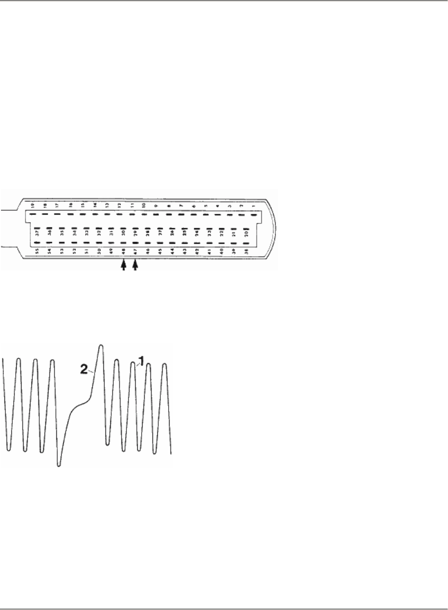
24/28 Fuel System - Electronic Control 944 S/944 S2
Test Point 21: Speed/Reference
Mark Sender
This test can only be performed with an oscillo-
scope. Connect and adjust a workshop oscillo-
scope according to the supplied operating
instructions for this purpose.
Connect the positive tester lead via a test lead
on control unit plug terminal 47 and negative
tester lead via a test lead on control unit plug
terminal 48.
Crank engine with the starter motor. Sinusoidal
oscillation of at least 3 volts (speed pulse) and
an applied higher amplitude (reference mark)
must be displayed on the screen.
If the voltage signal is too small (< 3 V), the
distance between the sender and gear ring
could be adjusted incorrectly.
Sender distance: Between gear ring and
sender: 0.8 +- 0.3 mm.
1 - Speed signal
2 - Reference mark signal
D 24/28 - 24 DME - Diagnosing/Troubleshooting
Printed In Germany - XXI, 1989
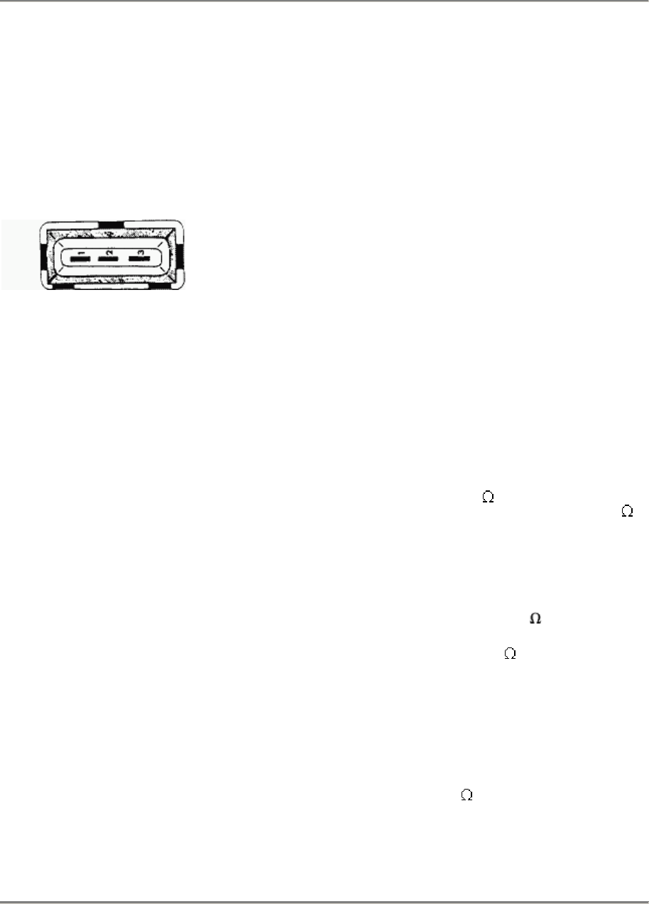
944 S/944 S2 Fuel System - Electronic Control 24/28
No display:
Disconnect plug of speed sender on plug
plate in the engine compartment. Connect
tester leads on middle and outside pins of
the plug on the sender end of the plug with
help of test leads (terminals 1 and 2, pin
end). Start the engine. Sinusoidal oscillation
must be displayed on the screen.
Speed sender plug
Remarks:
The display must remain unchanged after
supplying ground to connection 3.
If not, check power flow, spacing and
condition of the sender.
Test Point 22: Ignition
a) Secondary ignition display
Adjust secondary ignition display an the
oscilloscope. Connect tester leads according
to the supplied operating instructions.
Note:
If a fault is displayed for all cylinders, it is in
the primary or secondary circuit from the
ignition coil to the distributor rotor. If a fault is
displayed for one cylinder, this fault is
located after the distributor rotor.
Primary resistor:
Secondary
resistor:
Term.1 + 15 = 0.4-0.6
Term.1 + 4 = 5-7.2 k
b) Spark plug connectors ( )
Suppression resistor: 3 k
Visual inspection for damage or traces of
burning.
c) Distributor
Distributor rotor, distributor cap: suppression
resistor = each 1 k .
Visual inspection for damage, dirt or wrong
location.
DME - Diagnosing/Troubleshooting
Printed In Germany - XXI, 1989 D 24/28 - 25
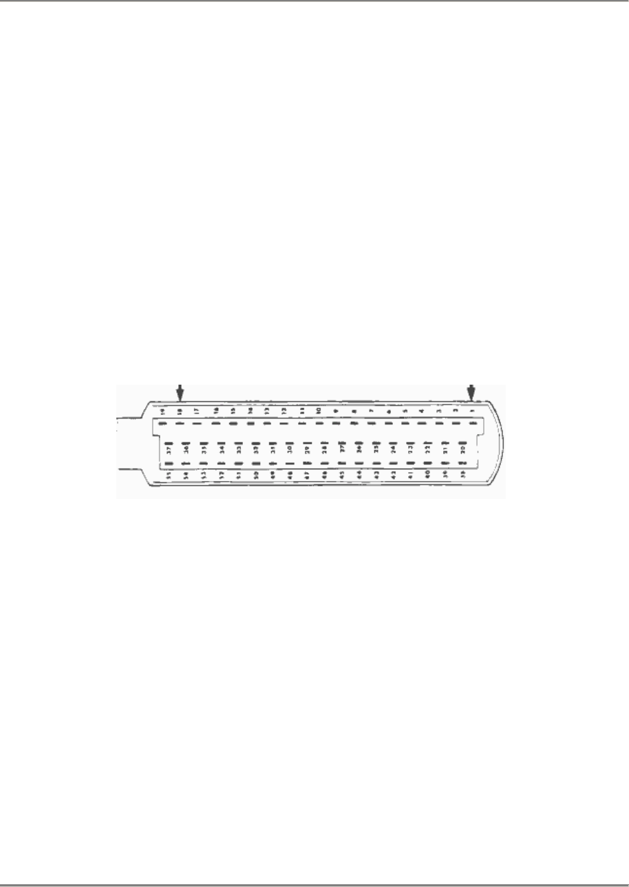
24/28 Fuel System - Electronic Control 944 S/944 S2
d) Ignition timing test
Ignition timing is checked with the engine at
operating temperature.
Ignition timing and engine speed can be
read direct in the "actual value" menu with a
9288 System Tester.
Test value: (944 S + 944 S2)
At 840 +- 40 rpm 10° +- 3°
e) Activation of high tension end
(if ignition sparks are not triggered)
Ignition triggering signal can be simulated for
fast troubleshooting of the ignition end. This
requires connecting the oscilloscope term. 4
tester lead on the ignition lead betw. ignition
cail and high tension distributor (term. 4).
Disconnect DME control unit plug.
Turn on ignition.
If battery voltage is new supplied
intermittently to terminal 1 of the control unit
with help of a test lead (e.g. control unit plug
term. 18), a high tension peak must be
displayed on the oscilloscope each time
(ignition triggering).
If there is no signal, check:
-
Power supply to ignition final stage and
ignition coil.
-
Ground connection for ignition final stage
(ground point on left front side member).
- Plug connections on ignition final stage,
ignition coil and high tension distributor.
-
Components responsible for high tension
(for example: ignition coil, ignition leads,
spark plug connectors, etc.).
- Power flow in lead between control unit
plug and ignition final stage term. 5.
D 24/28 - 26 DME - Diagnosing/Troubleshooting
Printed In Germany - XXI, 1989
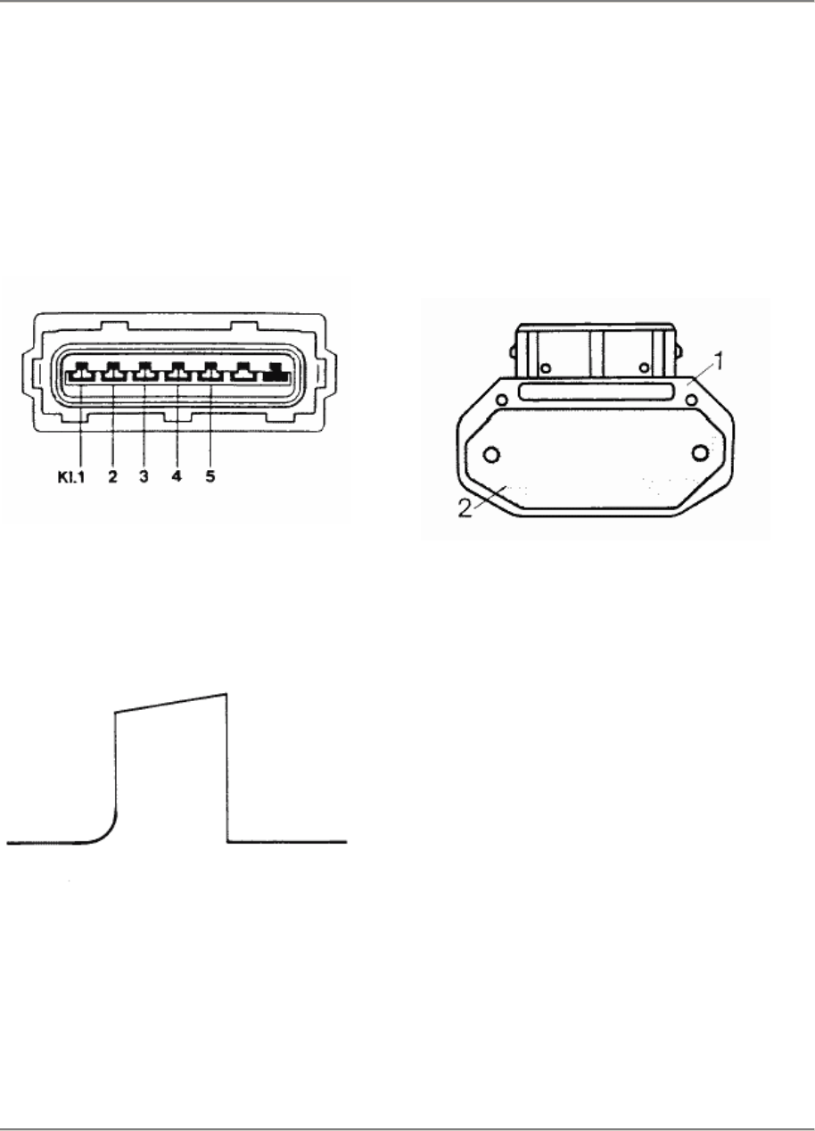
944 S/944 S2 Fuel System - Electronic Control 24/28
f) Ignition final stage control signal test
Connect DME control unit plug.
Connect oscilloscope's positive tester lead
on terminal 5 and negative tester lead on
terminal 2 of the disconnected final stage
plug.
Operate starter motor.
Oscilloscope should display the control
signal of the DME control unit.
Very important:
Coat the baseplate with a heat conducting
paste prior to installation of the ignition final
stage. Keep heat conducting paste off of
painted parts.
Heat conducting paste:
Bosch No. 5 942 860 003.
1 - Final stage
2 - Baseplate
DME - Diagnosing/Troubleshooting
Printed In Germany - XXI, 1989 D 24/28 - 27
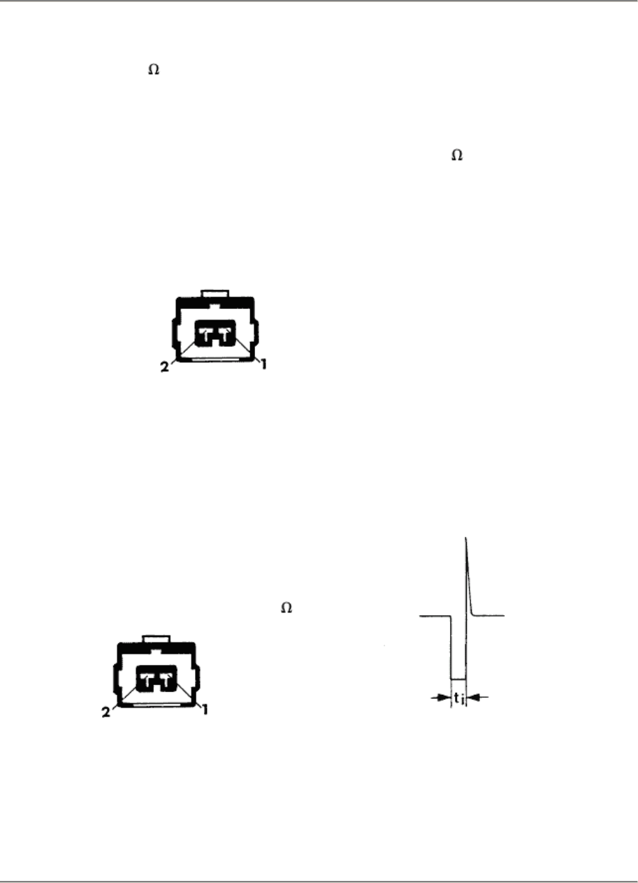
24/28 Fuel System - Electronic Control 944 S/944 S2
Test Point 23: Fuel Injectors -
Injection Timing (V/ )
Element activation menu:
If a pulse is not heard, check:
a) Power supply
Pull off injector plug. Connect voltmeter on
injector plug terminal 2 and ground with help
of test leads. Turn on ignition.
Display: battery voltage
If there is no dispiay:
Disconnect 5-pin plug of fuel injector ballast
resistors. Connect voltmeter between
terminal 3 (terminal sleeve end) and ground.
Turn on ignition.
If battery voltage is displayed, Turn off
ignition and pull off all plugs on fuel injectors.
Check power flow and resistance between
the S-pin plug of ballast resistors and
terminal 2 of each fuel injector plug with an
ohmmeter.
Resistance of each ballast resistor = 6
Check current path according to the wiring
diagram if battery voltage is not displayed.
b) Coil resistanee test of fuel injectors
Pull off injector plugs. Check coil resistance
on the contacts of the fuel injectors with an
ohmmeter.
Test value: 2 - 3
c) Injection final stage
Adjust oscilloscope according to the
supplied operating instructions. Connect
Bosch test lead (1 684 463 093) between
fuel injector and plug. Connect tester leads
on Bosch lead according to the supplied
operating instructions.
Caution:
Tester leads must not have any contact
with ground.
Start the engine. These displays must
appear in the oscilloscope if the injection
final stage is working perfectly and test
connections are correct.
Starter speed
Remarks:
If the engine cannot be started or the idle
speed drops, change tester connections on
the Bosch lead and check tester
adjustment.
D 24/28 - 28 DME - Diagnosing/Troubleshooting
Printed In Germany - XXI, 1989

944 S/944 S2 Fuel System - Electronic Control 24/28
Test Point 24: Alternator, Regulator
Misfiring of the engine could be caused by
the peak voltage of the alternator.
Take drive belt off of the alternator. Start the
engine.
Check alternator and regulator if the
disturbances have been eliminated.
Test Point 25: Leads K and L
Connections for diagnosing between the
DME control unit and fasters are made with
both leads K and L Check the folIowing
points when diagnosing is not possible.
1. Power flow test (see wiring diagram)
Lead L: Pin 7 (19-pin diagnostics socket) -
Pin 13 (DME plug)
Lead K: Pin 8 (19-pin diagnostics socket) -
Pin 55 (DME plug)
2. Ground short test (see wiring diagram)
Lead L: Voltage on Pin 7 (19-pin diagnostics
socket) must be > 8 V with the ignition
turned on.
Lead K: Voltage on pin 8 (19-pin diagnostics
socket) must be > 8 V with the ignition
turned on.
Possible Causes of Fault:
-
Ground short or break in wiring or plug
connections.
- Faulty control unit, which is connected on
these leads (could be any diagnosable
control unit; does not always have to be
the DME control unit).
Checking: Pull off plugs on diagnosable
control units one after the other until there
is
> 8 V. Replace fault-eausing control unit.
-
Tester faulty.
- Power supply lacking on diagnostics
socket.
- Ground supply lacking on diagnostics
socket.
Information for idle speed and idle speed
CO test:
a) Idle speed
944 S engines have adaptive idle speed
volumetric efficiency regulation since 1987
modeIs. This means that the idle speed of all
versions does not have to be adjusted. The
system of cars with adaptive idle speed
volumetric efficiency regulation should be
adapted each time the DME control unit had
been disconnected on permanent positive or
after each inspection.
Idle speed control value for engine at
operating temperature:
840 +- 40 rpm
b) Idle speed CO of cars without catalytic
converter
CO level is still adjusted on the CO adjusting
screw in the air flow sensor.
Requirements:
-
Engine at operating temperature.
- Engine and ignition in perfect running
condition.
- All electric consumers switched off.
- CO tester at operating temperature,
calibrated and adjusted correctly.
DME - Diagnosing/Troubleshooting
Printed In Germany - XXI, 1989 D 24/28 - 29

24/28 Fuel System - Electronic Control 944 S/944 S2
Adjusting value: 0.5 - 1.5 % CO
at 840 +- 40 rpm and ignition timing of
10° +- 3° before TDC.
Adapt the system after adjusting the CO level.
An adapter plug (911.612.422.8) must be con-
nected on the oxygen sensor connecting lead
of cars without a catalytic converter, in order
to avoid diffusion (see wiring diagram).
c) Idle speed CO of cars with catalytic
converter
In addition to adaptation of the idle speed
there is also adaptation of the idle speed CO
level in these cars, so that it is only necessary
to check the actual state in such cars.
Requirements:
-
Engine at operating temperature.
- Engine and ignition in perfect running
condition.
- All electric consumers switched off.
- CO tester at operating temperature,
calibrated and adjusted correctly.
- Oxygen sensor plug connected.
Test value: 0.4 - 1.2 % CO
at 840 +- 40 rpm and ignition timing of
10° +- 3° before TOC.
Afterwards the engine must be run at least
10 minutes after disconnection of the
control unit plug or disconnection of the
battery, before it will be possible to recheck
these values. In addition, the system must
be adapted.
D 24/28 - 30 DME - Diagnosing/Troubleshooting
Printed In Germany - XXII, 1990
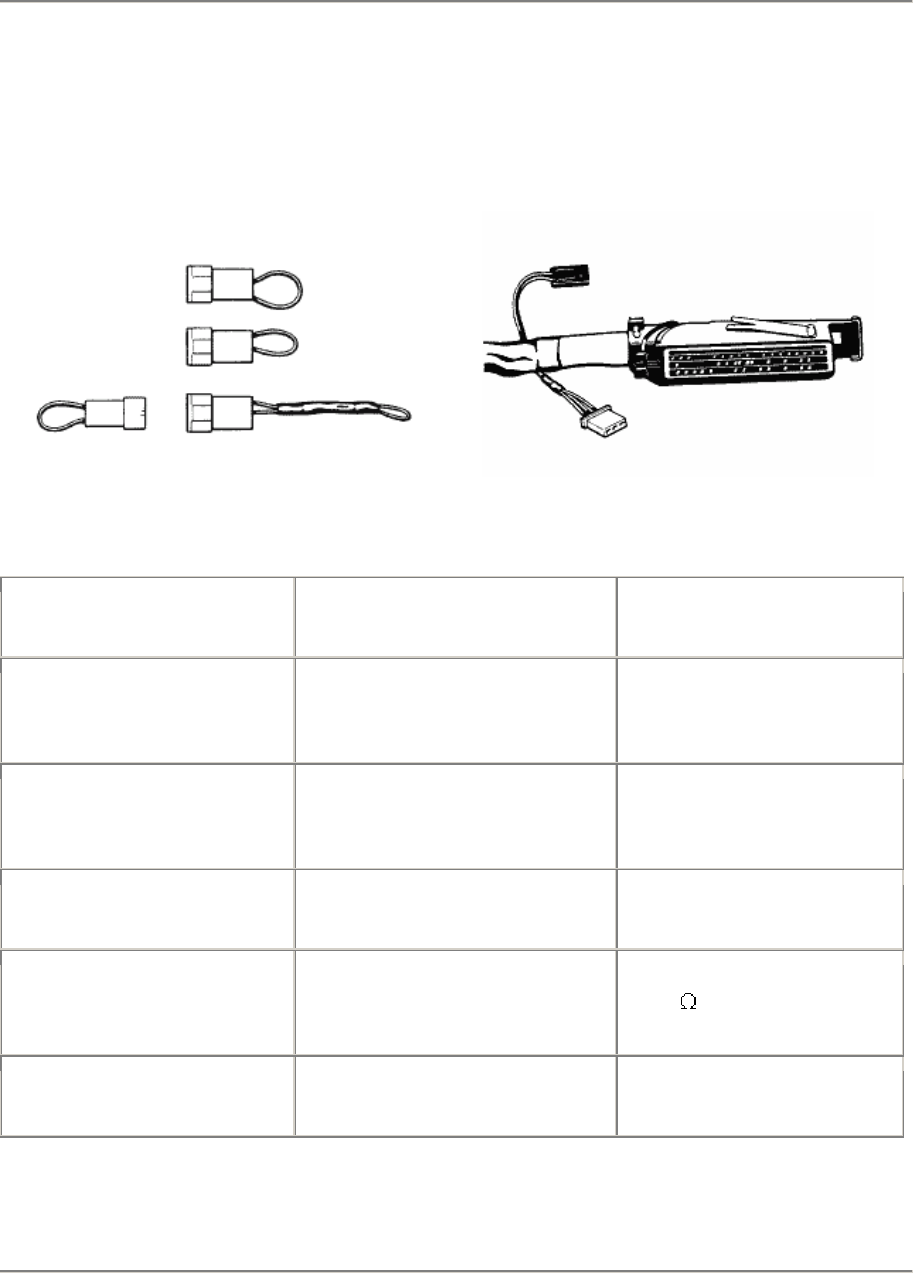
944 S/944 S2 Fuel System - Electronic Control 24/28
Coding of Control Unit - 944 S
Pertinent curve families are integrated in the DME control unit, in order to be able to comply
with the legislation of different countries. They can be read direct in the "actual value" menu
with a 9288 System Tester.
One each 2-pin and 3-pin plug, which are bridged differently depending on the country version,
lead out of the DME wire harness to call these curve families.
Country Curve Family Switch
2 Pins Version Switch
3 Pins
USA Federal States
FAG M 298
Oxygen sensor
- -
USA Califomia
Japan
Oxygen sensor
- Bridge against
battery voltage
928.607.421.00
ECE - Bridge against grd.
928.607.422.00
Sweden - Resistance
6.8 k against grd.
944.612.522.00
Australia
Oxygen sensor Bridge against ground
944.612.515.00 -
DME - Diagnosing/Troubleshooting
Printed In Germany - XXI, 1989 D 24/28 - 31

24/28 Fuel System - Electronic Control 944 S/944 S2
Coding af Control Unit - 944 S 2
Country Curve Family Switch
2 Pins Version Switch
3 Pins
All with cat. conv. - -
Califomia, Japan - Bridge against
battery +
928.607.421.00
All without cat. conv. - Bridge against grd.
928.607.422.000
As from model year '91, the code for California and Japan is being deleted (identical
worldwide).
D 24/28 - 32 DME - Diagnosing/Troubleshooting
Printed In Germany - XXII, 1990
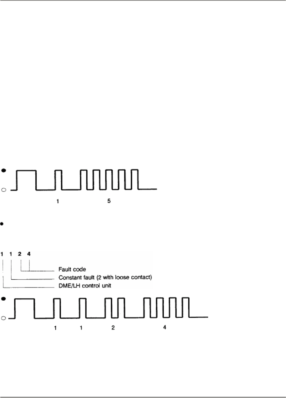
944 S/944 S2 Fuel System - Electronic Control 24/28
Check-Engine Lamp
(Malfunction Indicator Light M.I.L)
As from model year '91, Califomian legislation prescribes a waming lamp which lights up if a
part relevant to the exhaust gas fails.
As a function check of the warning lamp, it lights up when the ignition is switched on and goes
out once the engine is running when this is started without depressing the accelerator.
The waming lamp has a flashing code to indicate a defective fault path.
To trigger off the flashing code, fully depress the accelerator pedal with the engine off and the
ignition on for 3 seconds until the Malfunction Indicator Lamp flashes. Then remove foot from
accelerator.
If no fault is recorded, i.e. no warning came from the indicator light, there appears the flashing
code
1500
no fault.
= Lamp on o = Lamp off
If the waming light did indicate a warning, i.e. there is a fault, there appears a flashing code,
e.g.
1124
Oxygen sensor
The flashing code is listed in the Diagnosing/Troubleshooting plan on page D 24/28-7.
The fault can also be read direct using System Tester 9288. After a repair the fault memory
must be erased using the System Tester.
DME - Diagnosing/Troubleshooting
Printed In Germany - XXII, 1990 D 24/28 - 33
