Poulan Pro Lawn Mower Pb195A42Lt Users Manual IPL, PB195A42LT, 2010 10, TRACTORS/RIDE MOWERS, 96048000403
!! Poulan-70 Poulan Lawn Mower Manuals - Lawn Mower Manuals – The Best Lawn Mower Manuals Collection
2015-02-06
: Poulan-Pro Poulan-Pro-Lawn-Mower-Pb195A42Lt-Users-Manual-519950 poulan-pro-lawn-mower-pb195a42lt-users-manual-519950 poulan-pro pdf
Open the PDF directly: View PDF ![]() .
.
Page Count: 20
REPAIR PART'S MANUAL
MODEL:
PB195A42LT
LAWN TRACTOR
ALWAYS WEAR EYE PROTECTION DURING OPERATION
Visit our website: www.poulan-pro.com
WARNING:
Read this Man u al and follow all Warnings
and Safety Instructions. Fail ure to do so can
re sult in serious in ju ry.
IMPORTANT MANUAL Do Not Throw Away
532 43 88-83 10.25.10 BAD Printed in U.S.A.
2
HOW TO USE THIS MANUAL
This manual is designed to provide the customer with a means to identify the parts on his/her tractor
when ordering repair parts. The illustrations may or may not represent the actual assemblies; therefore,
it is not recommended to use this manual as a guide to assemble or disassemble the tractor. Some
hardware and parts are drawn larger in order to more readily identify them.
Each tractor has its own model number.
The model number for your tractor can be found on the fender under the seat.
When ordering parts, always give the following information:
• Product - “Tractor”
• MODEL NUMBER - “PB195A42LT (96048000400)”
• Part Number
• Part Description
TABLE OF CONTENTS
SCHEMATIC ................................................................................................................ 3
ELECTRICAL ............................................................................................................4-5
CHASSIS ..................................................................................................................6-7
DRIVE........................................................................................................................8-9
ENGINE .................................................................................................................10-11
STEERING ............................................................................................................12-13
MOWER DECK .....................................................................................................14-15
MOWER LIFT .............................................................................................................16
SEAT ..........................................................................................................................17
DECALS .....................................................................................................................18
WARRANTY ...............................................................................................................20
3
M
FUSE
STARTER
SOLENOID
BATTERY
CLUTCH/BRAKE
(PEDAL UP)
REVERSE SWITCH
(NOT IN REVERSE)
SEAT SWITCH
(NOT OCCUPIED)
SHORTING
CONNECTOR
CHASSIS
HARNESS
IGNITION
UNIT
HOUR
METER
CHASSIS HARNESS
CONNECTOR
(MATING SIDE)
DASH HARNESS
CONNECTOR
(MATING SIDE)
FUEL
LINE
FUEL SHUT-OFF
SOLENOID
(IF SO EQUIPPED)
JUNCTION
CONNECTOR
SM
B
GL
2
3
1
6
A2
A1
M
63
52
41
6
5
4
3
2
1
SPARK
PLUGS GAP
(2 PLUGS ON
TWIN CYL. ENGINES)
(OPTIONAL)
NON-REMOVABLE
CONNECTIONS
REMOVABLE
CONNECTIONS
WIRING INSULATED CLIPS
NOTE: IF WIRING INSULATED
CLIPS WERE REMOVED FOR
SERVICING OF UNIT, THEY
SHOULD BE RE-INSTALLED TO
PROPERLY SECURE YOUR
WIRING.
SCH11
IGNITION SWITCH
CIRCUIT
POSITION
OFF
B+A1
RUN/OVERRIDE
B+S+A1START
M+G+A1
B+A1RUN
“MAKE”
L+A2
ATTACHMENT CLUTCH
(CLUTCH OFF)
BLACK
BLACK /WHITE
BLUE
BLUE BLACK
BLACKBLACK
BLACK
BLACK
BLACK
BLACK
BLACK
D
E
R
RED
WHITE
WHITE
GRAY
GRAY
BLACK
BLACK
POWER OUTLET
(OPTIONAL)
12V
BLACK
A
AMMETER
(OPTIONAL)
RED
BLACK
BROWN
HEADLIGHTS
LIGHT SWITCH
ORANGE
LIGHTING SYSTEM OUTPUT
5AMPAC@3600RPM
ALTERNATOR
14 VOLTS AC MIN. @ 3600 RPM (LIGHTS OFF)
DIODE
28 VOLTS AC MIN. @ 3600 RPM
(CHARGING SYSTEM DISCONNECTED)
CHARGING SYSTEM OUTPUT
3AMPDC@3600RPM
NOTE
YOUR TRACTOR IS
EQUIPPED WITH A SPECIAL
ALTERNATOR SYSTEM.
THE LIGHTS ARE NOT
CONNECTED TO THE
BATTERY, BUT HAVE THEIR
OWN ELECTRICAL SOURCE.
BECAUSE OF THIS, THE
BRIGHTNESS OF THE LIGHTS
WILL CHANGE WITH ENGINE
SPEED. AT IDLE THE LIGHTS
WILL DIM. AS THE ENGINE IS
SPEEDED UP, THE LIGHTS
WILL BECOME THEIR
BRIGHTEST.
REPAIR PARTS
TRACTOR - - MODEL NUMBER PB195A42LT (96048000400), PRODUCT NO. 960 48 00-04
SCHEMATIC
4
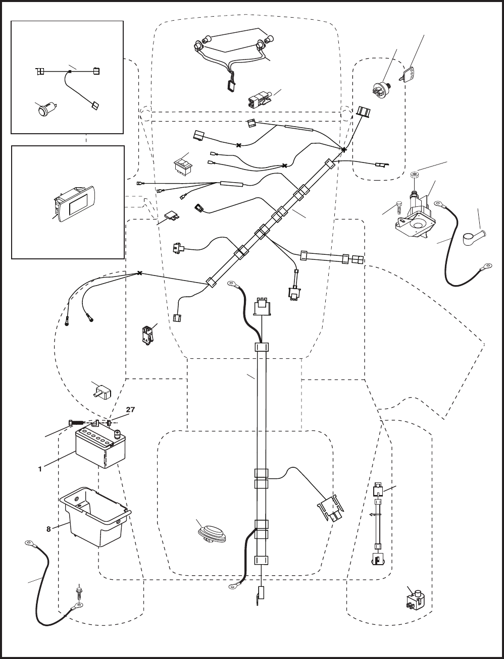
REPAIR PARTS
TRACTOR - - MODEL NUMBER PB195A42LT (96048000400), PRODUCT NO. 960 48 00-04
ELECTRICAL
30
33
34
22
79 21
41
42
26
43
27
40
71
16
87
25
T06S
90
28
55
With 12V Outlet Option
59
103
With Service Minder Option
4646
102
29
2
105
5
REPAIR PARTS
TRACTOR - - MODEL NUMBER PB195A42LT (96048000400), PRODUCT NO. 960 48 00-04
ELECTRICAL
KEY PART
NO. NO. DESCRIPTION
1 532 16 34-65 Battery
2 874 76 04-12 Bolt Hex Hd 1/4-20 unc x 3/4
8 532 19 32-28 Box Battery
16 532 17 61-38 Switch Interlock
21 532 18 37-59 Harness Socket Light
22 532 00 41-52 Bulb, Light #1156
25 532 41 28-94 Cable Starter 6 Ga. BL/Red 14.5
26 532 17 51-58 Fuse
27 873 51 04-00 Nut Keps Hex 1/4-20 unc
28 532 19 88-85 Cable Ground 18" Rear Battery Blk 6 Ga.
29 532 40 15-45 Switch Seat
30 532 19 33-50 Switch Ign
33 532 41 19-35 Key/Chain
34 532 11 07-12 Switch Light/Reset
40 532 40 10-98 Harness Ign
41 817 72 04-08 Screw 1/4-20 unc x 1/2
42 532 13 15-63 Cover Terminal Red
43 532 19 25-07 Solenoid
55 817 06 05-12 Screw 5/16-18 x 3/4
71 532 40 04-49 Harness Ign. Chass.
79 532 17 52-42 Socket Asm. Bulb
87 532 19 78-02 Switch Interlock Clutch
90 532 43 53-95 Cover Terminal
102 532 41 97-81 Pigtail Rev. GT Vatr.
105 532 40 75-68 Switch Reverse
NOTE: All component dimensions given in U.S. inches
1 inch = 25.4 mm
6
37
181
194
194
36
162
181
196
287
138
182
176
175
177
176
130
151
5
137
14
18
176
176
153
302
Chassis-tex_elite basic_13
130
150
68
68
68
68
183
183
236
236
34
235
235
52
217
189
189
152
68
68
213
218
58
189
189
228
180
228
194
159
159
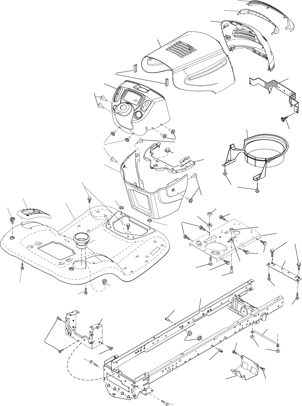
REPAIR PARTS
TRACTOR - - MODEL NUMBER PB195A42LT (96048000400), PRODUCT NO. 960 48 00-04
CHASSIS
7
5 532 41 17-64 Dash
14 532 18 58-47 Hood
18 532 42 67-92 Grille
34 532 19 61-25 Plate Engine
36 817 06 05-12 Screw 5/16-18 x 3/4
37 532 43 65-23 Fender
52 873 68 05-00 Nut Lock 5/16-18
58 532 41 22-80 Drawbar Upper
68 817 49 05-08 Screw Thdrol 5/16-18 x 1/2
130 532 41 63-58 Screw #10 x 0.750
137 532 18 49-21 Bumper Hood
138 532 40 97-30 Cupholder
150 532 18 44-61 Duct Heat Hood
151 532 40 78-07 Bracket Pivot
152 532 19 95-35 Shield Browning
153 532 18 98-37 Lens Grille
159 817 00 06-12 Screw Hexwsh Thdrol 3/8-16 x 3/4
162 532 14 24-32 Screw Hex Wsh Hi-Lo 1/4 x 1/2
175 532 19 32-43 Crossmember
176 532 40 07-76 Screw 10-24 x 5/8 Wshd Qdrx
177 532 19 52-28 Bushing Steering
180 532 41 50-63 Chassis
181 532 40 47-96 Bushing Mtg. Fender Crgo.
182 532 19 30-57 Dash Lower
183 874 52 05-20 Bolt 5/16-18 x 1-1/4
189 817 00 05-12 Screw 5/16-18 x 3/4
194 873 90 05-00 Nut Lock Hex Flange 5/16-18
196 532 41 45-79 Console Asm. Deck Lift
213 874 76 05-12 Bolt 5/16-18 x 3/4
217 532 40 91-67 Rod Pivot Hood
218 532 19 63-95 X-Piece Hood Step
228 532 19 51-61 Stud Fastener
235 532 40 61-29 Spacer Fender
236 873 93 05-00 Nut Center Lock 5/16-18
287 817 60 04-06 Screw 1/4-20 x 3/8
302 532 18 38-23 Insert Lens Reflective
REPAIR PARTS
TRACTOR - - MODEL NUMBER PB195A42LT (96048000400), PRODUCT NO. 960 48 00-04
CHASSIS
NOTE: All component dimensions given in U.S. inches
1 inch = 25.4 mm
KEY PART
NO. NO. DESCRIPTION
8
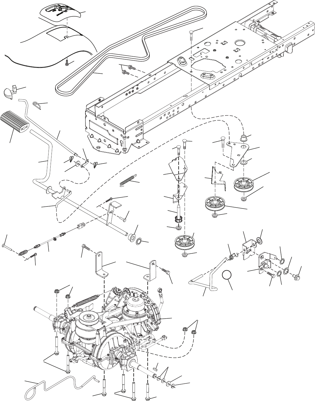
REPAIR PARTS
TRACTOR - - MODEL NUMBER PB195A42LT (96048000400), PRODUCT NO. 960 48 00-04
DRIVE
56
186
189
49
190
187
50
51
52
51
51
51
302
301
300
303
70
74
166
297
125
22
178
176
232
233
23
175
174
305
295
drive-tex_VATR_6
166
165
298
131
73
296 296
205
2
37
33
116
73
99
116
1
172
125
125
131
160
160
203
35
64
188
42
161
184
221
167
299
303
143
185
9
REPAIR PARTS
TRACTOR - - MODEL NUMBER PB195A42LT (96048000400), PRODUCT NO. 960 48 00-04
DRIVE
KEY PART
NO. NO. DESCRIPTION
NOTE: All component dimensions given in U.S. inches
1 inch = 25.4 mm
1 ---------- Transmission, Gentrans
2 532 12 35-83 Key.Square .2.0 x .1845/.1865
22 532 42 10-63 Rod Shift
23 532 14 08-45 Knob
33 812 00 00-01 E-Ring. #5133-75
35 532 19 77-22 Rod.Brake.Parking. Lt.Tex
37 532 12 17-49 Washer.25/32 X 1 1/4 x 16 Ga.
42 532 12 48-72 Cover.Pedal.Blk.Round
49 872 11 06-14 Bolt.Rdhd.3/8-16Uncx1-3/4.Gr 5
50 532 19 43-27 Idler.Flat.910"Offset
51 873 90 06-00 Nut, Hex, Flangelock 3/8-16
52 532 19 43-26 Idler.V-Groove.910"Offset
56 532 19 72-53 Belt.Drive.100.97"
64 532 19 62-00 Shaft Asm.Pedal.Brake Control
70 532 44 03-23 Console
73 874 49 05-44 Bolt.Hex.Flghd.5/16-18.Gr.5
74 532 14 24-32 Screw.Hex.Wsh.Hi-Lo.1/4X1/2 unc
99 532 42 73-40 Rod Bypass
116 873 90 05-00 Nut, Lock Hex Flange 5/16-18 unc
125 817 00 05-12 Screw.5/16-18 x 3/4.Smgml.Tap/Bl
131 876 02 03-12 Pin Cotter 3/32/ x 3/4
143 817 49 05-08 Screw.Thdrol.5/16-18 x 1/2 Tytt
160 532 16 94-84 Retainer.Clip(M).Dia.290
161 532 10 57-09 Spring.Return.Clutch.6.75
165 532 19 62-12 Bushing.Shaft.Brake.Hand Contr
166 532 42 91-64 Nut Push .625
167 532 40 52-57 Latch.Brake.Parking
172 532 41 56-64 Strap Torque Lh/Rh
174 532 19 72-89 Nut.Push..500
175 532 41 56-77 Shaft Asm Shift
176 532 19 62-14 Arm.Clevis.Rod.Shift
178 532 19 74-56 Spring.Shift.Gt.2006
184 532 41 12-89 Handle.Parking Brake.Lttex.505
185 872 11 06-22 Bolt.Rdhd.3/8-16Unc x 2-3/4 Gr5
186 532 19 43-21 Spacer.Retainer
187 819 13 32-10 Washer.13/32 x 2 x 10 Ga.
188 532 19 43-23 Link.Clutch.Ground Drive
189 532 19 43-17 Bellcrank.Groundrive.Nstg/Nstl
190 532 19 43-18 Keeper.Bellcrank.Drive.Ground
203 819 11 11-16 Washer 11/32 x 11/16 x 16 Ga.
205 532 12 17-48 Washer.25/32 x 1-5/8 x 16Ga.
221 532 40 31-87 Retainer.Spring.Clip.Handle
232 874 78 07-16 Bolt.Fin Hex.7/16-14 x 1 Gr5
233 532 40 52-96 Washer.Serrated
295 532 42 03-06 Pin Clevis 183 Od x 1.260 Long
296 532 42 04-71 Screw Thdrol 5/16-18 x 3
297 532 42 02-23 Nut Push 1/4
298 532 41 56-94 Pin Clevis Cbl. Brk. Variator
299 532 41 56-83 Bracket Mount Idler
300 532 41 56-81 Keeper Idler Rear
301 532 41 56-80 Pulley Idler V-Groove
302 532 41 56-66 Pulley Idler Flat 2.0 Od
303 872 11 06-18 Bolt Rdhd Sgnk 3/8-16 x 2-1/4
305 532 41 56-92 Cable Brake Variator
10
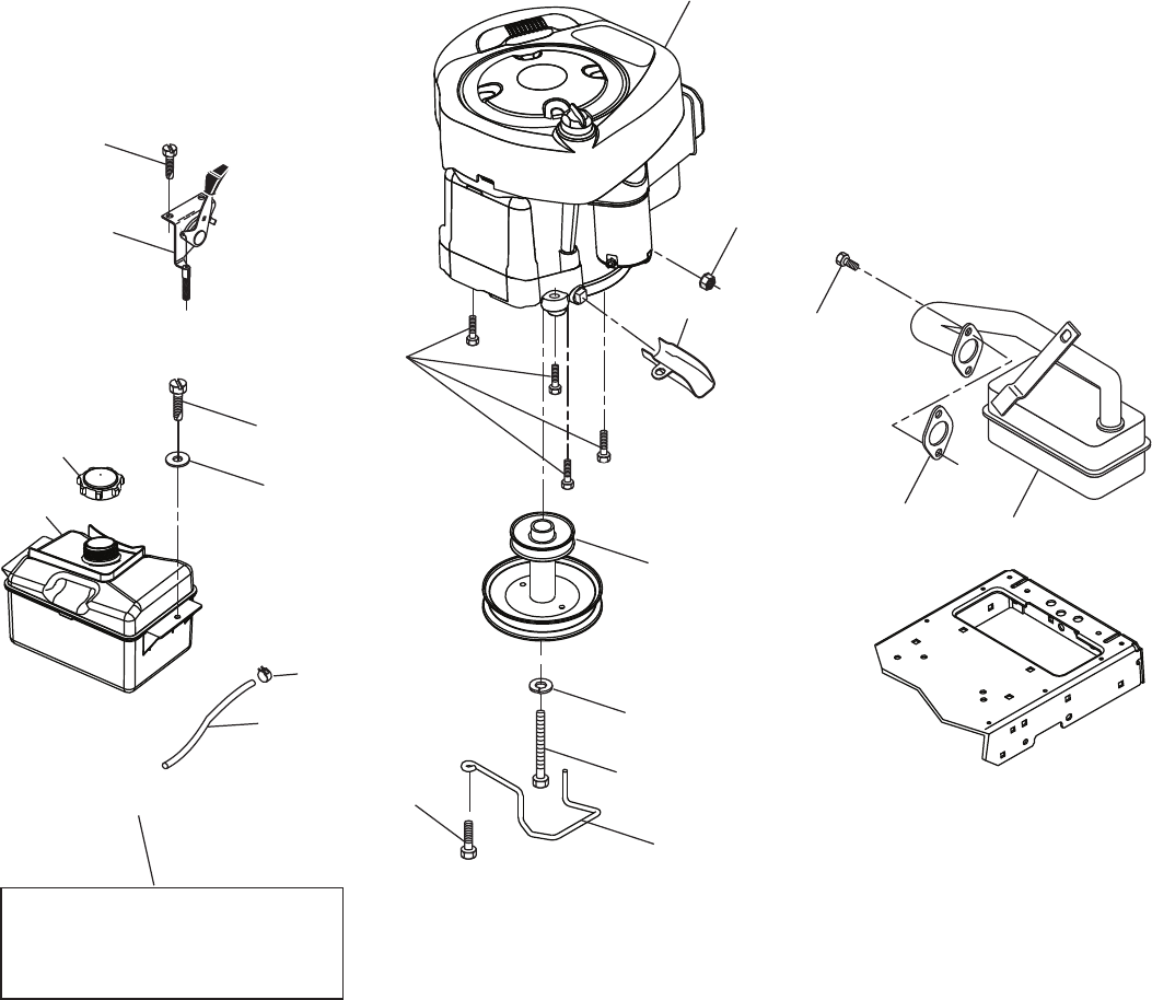
REPAIR PARTS
TRACTOR - - MODEL NUMBER PB195A42LT (96048000400), PRODUCT NO. 960 48 00-04
ENGINE
21
20
OPTIONAL EQUIPMENT
Spark Arrester
29
18 97
96
15
37
28
engine-tex_BS_30
12
42
85
9
90
69 2
79
84
45
1
122
11
1 - - - - - - Engine B&S Model No. 31P677-1517-B1
2 532 13 73-52 Muffler
9 532 19 43-19 Keeper Belt Engine
12 532 40 19-85 Pulley Engine
15 532 40 75-45 Tank Fuel 1.50
18 532 43 02-20 Cap Fuel
20 532 17 05-45 Control Throttle/Choke
21 532 41 63-58 Screw #10 x 0.750
28 532 40 11-37 Fuel Line
29 532 13 71-80 Spark Arrester Kit
37 532 12 34-87 Clamp Hose
42 810 04 07-00 Washer Lock 7/16
45 873 51 04-00 Nut Keps Hex 1/4-20 unc
69 532 16 52-91 Gasket
79 532 19 23-34 Screw Socket Hd 5/16-18 x .75
84 817 06 06-20 Screw 3/8-16 x 1-1/4
85 532 17 39-37 Bolt Hex 7/16-20 x 4 x Gr. 5-1.5
90 817 00 06-16 Screw 3/8-16 x 1.0
96 819 09 14-16 Washer 9/32 x 7/8 x 16 Ga.
97 817 67 04-12 Screw 1/4-20 x 3/4
122 532 42 19-22 Extension Drain Oil
REPAIR PARTS
TRACTOR - - MODEL NUMBER PB195A42LT (96048000400), PRODUCT NO. 960 48 00-04
ENGINE
KEY PART
NO. NO. DESCRIPTION
Engine Power Rating Information
The gross power rating for individual gas engine models is labeled in accordance with SAE (Society of Automotive
Engineers) code J1940 (Small Engine Power & Torque Rating Procedure), and rating performance has been obtained
and corrected in accordance with SAE J1995 (Revision 2002-05). Torque values are derived at 3060 RPM; horsepower
values are derived at 3600 RPM. Actual gross engine power will be lower and is affected by, among other things, ambi-
ent operating conditions and engine-to-engine variability. Given both the wide array of products on which engines are
placed and the variety of environmental issues applicable to operating the equipment, the gas engine will not develop
the rated gross power when used in a given piece of power equipment (actual “on-site” or net power). This difference is
due to a variety of factors including, but not limited to, accessories (air cleaner, exhaust, charging, cooling, carburetor,
fuel pump, etc.), application limitations, ambient operating conditions (temperature, humidity, altitude), and engine-to-
engine variability. Due to manufacturing and capacity limitations, Briggs & Stratton may substitute an engine of higher
rated power for this Series engine.
NOTE: All component dimensions given in U.S. inches
1 inch = 25.4 mm
For engine service and replacement parts, call the toll free
number for your engine manufacturer listed below:
Briggs & Stratton 1-800-233-3723
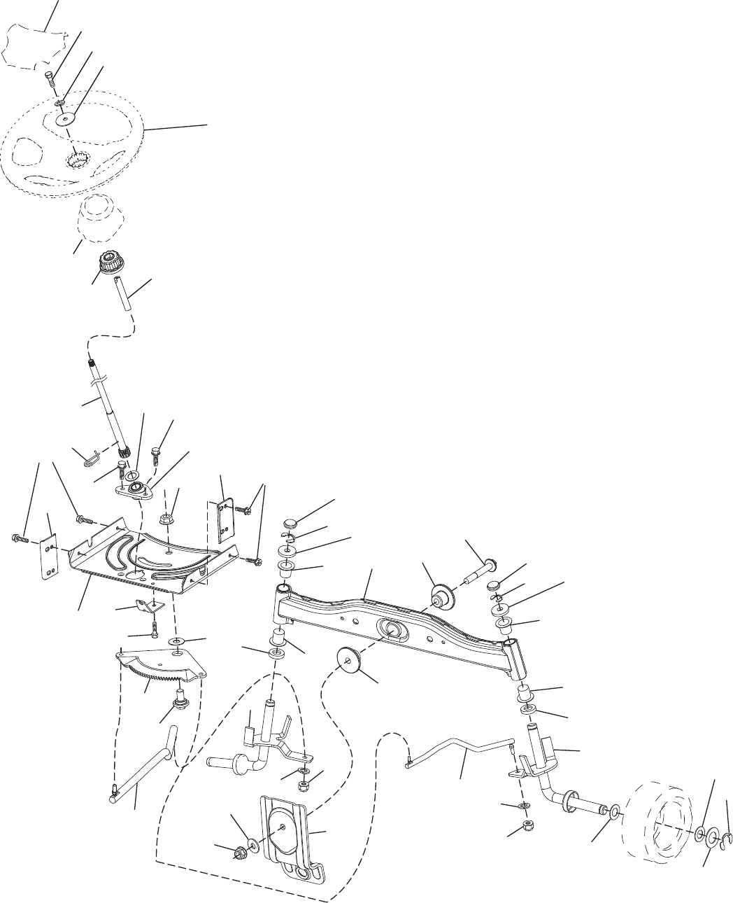
12
61
steering-tex_STDHRR_2_r2
19
60
59
58
5
62
15
14
13
13
53
8
70
68
69
16
28
28
13
22
64
4
15
14
35
6
74
9
8
74
7
9
87
67
67
66
74
74
6
2
63
57
57
63
20
1
21 71
72
33
45
26
120
121
REPAIR PARTS
TRACTOR - - MODEL NUMBER PB195A42LT (96048000400), PRODUCT NO. 960 48 00-04
STEERING
13
1 532 42 46-17 Wheel, Steering
2 532 41 81-68 Axle Asm., Front
4 532 40 30-87 Spindle Asm., LH
5 532 40 30-88 Spindle Asm., RH
6 532 12 49-31 Washer Thrust 0.75 x 1.23
7 532 12 17-48 Washer 25/32 x 1-5/8 x 16 Ga.
8 812 00 00-29 Ring, Clip #T5304-75
9 532 12 12-32 Cap, Spindle
13 532 12 17-49 Washer 25/32 x 1-1/4 x 16 Ga.
14 810 04 06-00 Washer Lock 3/8
15 873 54 06-00 Nut, Crown Lock 3/8-24 unf
16 532 42 93-74 Shaft Steering
19 532 19 47-29 Plate Steering
20 532 41 12-91 Boot, Steering
21 532 18 67-37 Adapter, Wheel Steering
22 532 42 05-37 Strg. Supt. Lower
26 532 42 45-53 Insert, Wheel Steering
28 817 00 06-12 Screw 3/8-16 x 3/4
33 810 04 05-00 Washer Lock 5/16
35 532 19 47-32 Gear, Sector Plate
45 819 11 38-12 Washer 11/32 x 2-3/8 x 12 Ga.
53 532 18 89-67 Washer Hardened .793 x 1.637 x .060
57 532 40 74-65 Bracket Upstop
58 532 19 47-47 Bolt Shoulder Sector Pivot CFM
59 532 19 47-48 Washer Thrust Sector Steering
60 873 97 10-00 Nut Flange Lock 5/8-11
61 532 19 47-40 Draglink, LH
62 532 19 47-41 Draglink, RH
63 817 00 05-12 Screw 5/16-18 x 3/4
64 532 19 98-49 Retainer Clip Spring Steering
66 871 02 07-48 Bolt Hex Fghd 7/16-14 x 3 Serr
67 532 19 47-37 Bushing PM Front Axle
68 873 90 07-00 Nut Lock Flange 7/16-14 Gr. 5
69 532 19 91-62 Washer 1.5 x .505 x .118
70 532 19 61-97 Bracket Deck Susp. Front
71 532 19 07-52 Shaft Ext. Steering
72 532 42 89-82 Bolt 5/16-18 x 4 W/Patch
74 532 12 49-37 Bearing
120 532 41 56-89 Bracket Locator
121 817 49 05-08 Screw 5/16-18 x 1/2
REPAIR PARTS
TRACTOR - - MODEL NUMBER PB195A42LT (96048000400), PRODUCT NO. 960 48 00-04
STEERING
NOTE: All component dimensions given in U.S. inches
1 inch = 25.4 mm
KEY PART
NO. NO. DESCRIPTION
14
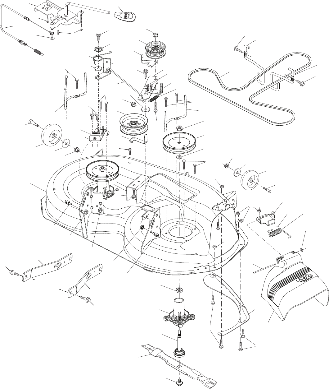
REPAIR PARTS
TRACTOR - - MODEL NUMBER PB195A42LT (96048000400), PRODUCT NO. 960 48 00-04
MOWER DECK
?$?MANTEX?,4??R
70
7
7
37
67
152
15
REPAIR PARTS
TRACTOR - - MODEL NUMBER PB195A42LT (96048000400), PRODUCT NO. 960 48 00-04
MOWER DECK
1 532 19 99-11 Mower Housing
6 532 19 51-86 Arm Suspension
7 532 41 63-58 Screw #10 x 0.750 BOS Thread
8 532 19 30-03 Bolt/Washer Asm 7/16-20 unf
11 532 13 89-71 Blade, 42" Hi-Lift
(For bagging or discharge)
- - 532 13 97-75 Blade, 42" Mulching Premium
(For better wear when mulching)
- - 532 13 41-49 Blade, 42" Mulching Std
(For mulching mowers only)
- - 532 42 47-52 Blade 42SP" 3N1
- - 532 42 27-19 Blade 42SP" Premium
13 532 19 28-72 Shaft Assembly, Mandrel
14 532 18 72-81 Housing, Mandrel
15 532 11 04-85 Bearing, Ball, Mandrel
19 532 19 65-39 Bolt, Shoulder
20 532 15 97-70 Baffle, Vortex
21 873 68 05-00 Nut, Crownlock 5/16-18 unc
23 532 19 25-57 Bracket, Deflector
24 532 10 53-04 Cap, Sleeve
25 532 19 70-26 Spring, Torsion, Deflector
26 532 11 04-52 Nut, Push
27 532 40 30-04 Shield, Deflector
29 532 13 14-91 Rod, Hinge
30 532 17 39-84 Screw Thdrol Rolling Wsh Hd
31 532 18 76-90 Washer, Spacer
32 532 19 74-73 Pulley, Mandrel
33 532 40 02-34 Nut, Toplock, Flanged
34 872 11 06-12 Bolt Carr Sh. 3/8-16 x 1-1/2 Gr. 5
36 532 19 73-79 Pulley, Idler 4.50 RAW
37 819 13 13-16 Washer 13/32 x 13/16 x 16 Ga.
38 532 43 25-20 Keeper Belt Mandrel
40 873 90 06-00 Nut, Lock Flg. 3/8-16 unc
42 532 19 84-10 Spring Torsion Brake
43 532 19 72-56 Spring Torsion Retainer
46 532 13 77-29 Screw Thd Roll 1/4-20 x 5/8
47 532 19 72-50 Bracket Clutch Cable
55 532 43 71-10 Arm, Idler
56 532 19 90-92 Spacer, Retainer
57 817 00 06-16 Screw Hexwsh Thd 3/8-16 x 1
59 532 14 10-43 Guard, Tuv Idler (94)
60 532 19 72-61 Arm Brake Mower
62 872 11 06-16 Bolt Rdhd Sqnk 3/8-16 unc x 2
63 532 19 94-77 Arm Brake Mower
64 532 19 97-90 Linkage Brake
67 532 40 30-12 Handle, Clutch Cable
68 532 42 96-36 V-Belt
69 872 14 05-05 Bolt Rdhd Sqnk 5/16-18 x 5/8
70 532 19 83-32 Clutch Asm. Manual
113 817 00 05-10 Screw 5/16-18
116 532 12 48-42 Bolt Shoulder
117 532 18 86-06 Wheel Gage
118 873 93 06-00 Nut Centerlock 3/8-16 unc
119 819 12 14-14 Washer 3/8 x 7/8 x 14 Ga.
122 532 19 72-58 Keeper Belt Eng. LH
123 532 19 72-59 Keeper Belt Eng. RH
144 532 19 92-04 Keeper Belt
145 532 19 31-97 Pulley Idler Primary
147 532 40 19-71 Spring Return
152 532 43 51-11 Cable Clutch Manual w/Spr.
188 532 19 51-61 Stud Fastener
189 873 90 05-00 Nut Lock Hex Flange
192 532 19 72-60 Bracket Brake Stand LH
195 817 00 06-12 Screw Hexwsh Thdr 3/8-16 x 3/4
208 817 67 06-08 Screw THDROL 3/8-16 x 1/2
- - 532 19 28-70 Mandrel Assembly (Includes
housing, shaft assembly, and
bearing only - pulley/nut/washer
and blade bolt/washers not in-
cluded)
- - 532 41 52-41 Replacement Mower, Complete
KEY PART
NO. NO. DESCRIPTION KEY PART
NO. NO. DESCRIPTION
NOTE: All component dimensions given in U.S. inches
1 inch = 25.4 mm
16
7
3
87
10
88
2
89
90 98
97
97
lift-tex_17_r3 *Key 91 may be substituted for Key 101
91
101*
87
100
89
89
87
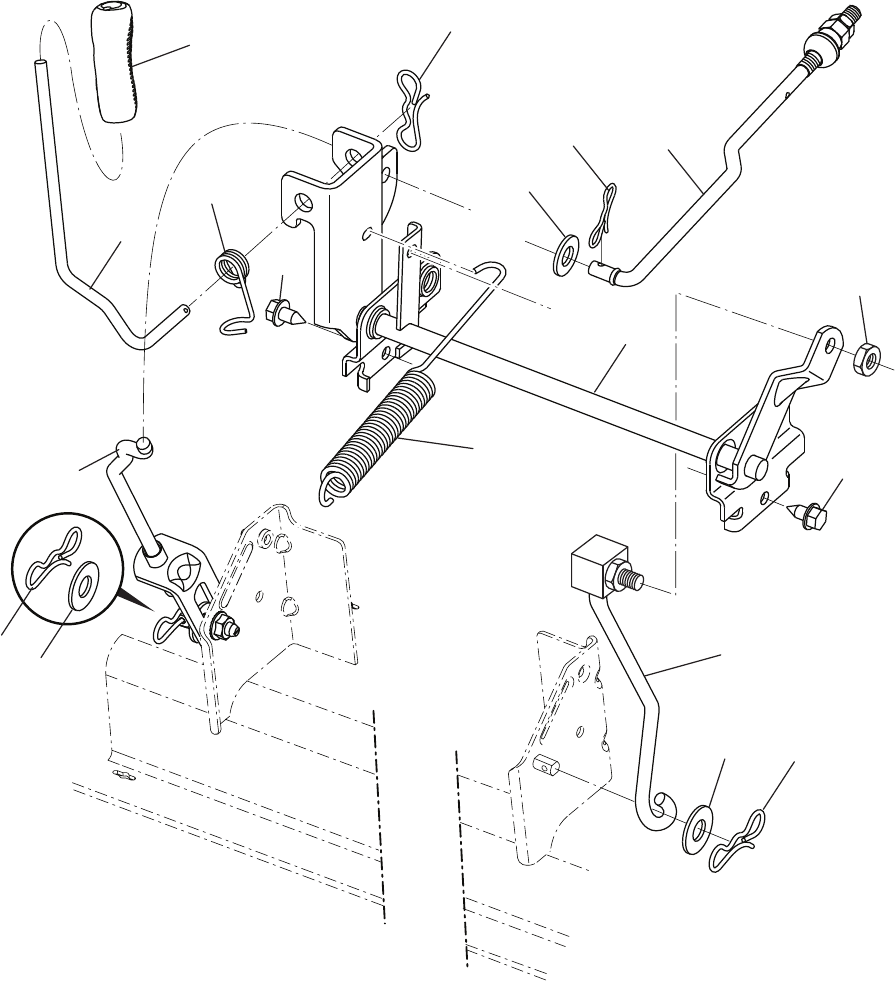
2 532 42 20-27 Shaft Asm., Cross Lift
3 532 19 52-31 Lever Asm., Lift RH
7 532 41 15-55 Grip, Lever
10 532 19 63-14 Spring Torsion
87 532 19 42-09 Pin Cotter 7/16 Bow Tie Lock
88 532 41 07-10 Spring Lift Assist
89 819 19 19-12 Washer Clear Zinc
90 532 19 42-08 Pin Cotter 5/16 Bow Tie Lock
REPAIR PARTS
TRACTOR - - MODEL NUMBER PB195A42LT (96048000400), PRODUCT NO. 960 48 00-04
MOWER LIFT
KEY PART
NO. NO. DESCRIPTION
NOTE: All component dimensions given in U.S. inches
1 inch = 25.4 mm
91 532 19 51-81 Link Lift Susp Mower Rear
97 817 00 06-12 Screw 3/8-16 x .75 Smgml Tap/R.Z
98 532 19 52-70 Link Lift Susp. Front Mower
100 873 93 06-00 Nut Centerlock 3/8 -16 unc
101 532 40 70-03 Link Asm. Lift Fixed
KEY PART
NO. NO. DESCRIPTION
17
2
6
1
40
10
37
37
21
21
3
41
7
8
7
8
8
8
seat-tex_6.5SL_2
44
43
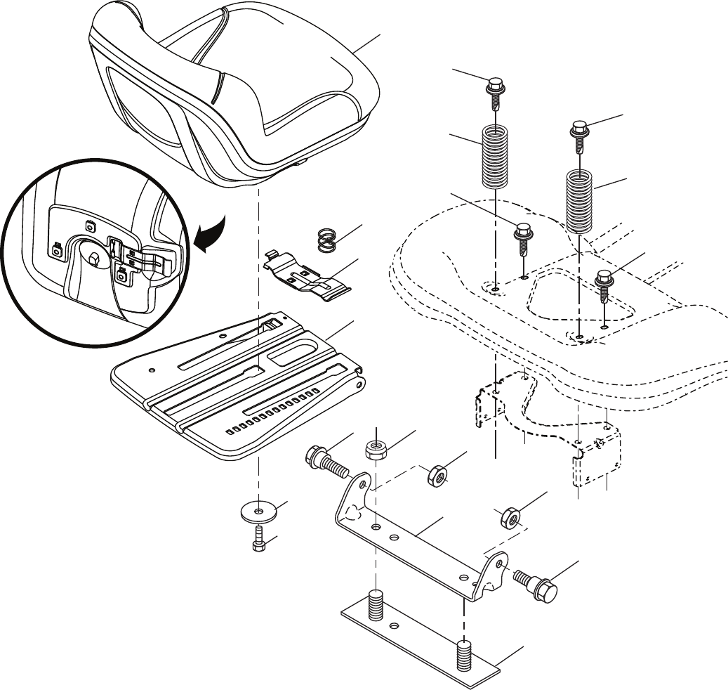
1 532 19 75-14 Seat
2 532 18 01-66 Bracket Pivot Fender
3 532 14 06-75 Strap, Asm Fender
6 873 80 06-00 Nut, Lock w/Ins. 3/8-16 unc
7 532 12 41-81 Spring, Seat Cprsn
8 532 17 18-77 Bolt 5/16-18 unc x 3/4 w/Sems
10 532 19 69-77 Pan, Seat
21 532 17 18-52 Bolt, Shoulder 5/16-18
37 873 80 05-00 Nut, Lock 5/16-18 unc
40 532 19 76-61 Handle Slide
41 532 19 82-00 Spring Latch
43 874 76 06-12 Bolt 3/8-16 unc x 3/4
44 819 13 38-12 Washer 13/32 x 2 3/8 x 12 Ga.
REPAIR PARTS
TRACTOR - - MODEL NUMBER PB195A42LT (96048000400), PRODUCT NO. 960 48 00-04
SEAT
KEY PART
NO. NO. DESCRIPTION KEY PART
NO. NO. DESCRIPTION
NOTE: All component dimensions given in U.S. inches
1 inch = 25.4 mm
18
REPAIR PARTS
TRACTOR - - MODEL NUMBER PB195A42LT (96048000400), PRODUCT NO. 960 48 00-04
NOTE: All component dimensions given in U.S. inches
1 inch = 25.4 mm
KEY PART
NO. NO. DESCRIPTION
6
2
1
3
11
4
10
5
9
8
7
wheel_art_1-tex
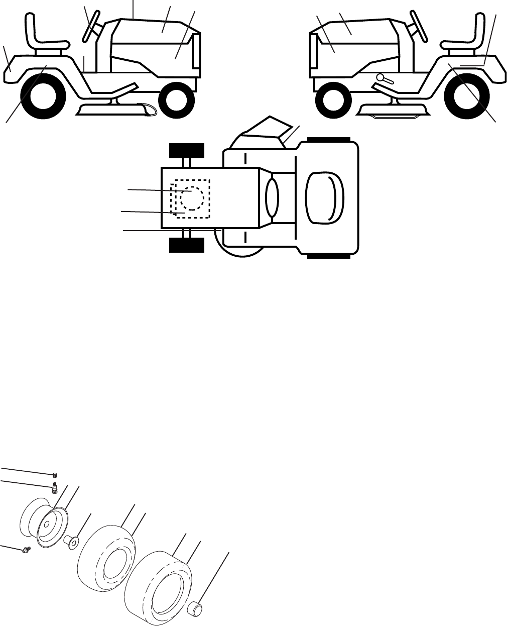
WHEELS AND TIRES
KEY PART
NO. NO. DESCRIPTION KEY PART
NO. NO. DESCRIPTION
3
3
9
1 532 05 91-92 Cap Valve Tire
2 532 06 51-39 Stem Valve
3 532 10 67-32 Rim Asm 6" Front
4 532 05 99-04 Tube Front (Service Item Only)
5 532 10 62-22 Tire F T 15 x 6 0 - 6
6 532 12 49-57 Fitting Grease (Front Wheel Only)
7 532 12 49-59 Bearing Flange (Front Wheel Only)
8 532 17 50-39 Cap Axle
9 532 42 05-31 Tire R T 18 x 9.5-8C Turf Saver LT
10 532 12 49-26 Tube Rear (Service Item Only)
11 532 10 61-08 Rim Asm 8" Rear Service
- - 532 14 43-34 Sealant, Tire (Not Shown)
20
14
1
2
1 532 43 52-86 Decal, Warn Spark
2 532 42 95-55 Decal Eng. H.P.
3 532 43 01-13 Decal Hood
4 532 43 90-74 Decal Side Panel Logo
6 532 17 05-63 Decal Warning, Keep Hand Away
7 532 43 88-05 Decal Replacement Parts
8 532 41 16-58 Decal Fender Warn S/F
9 532 43 01-12 Decal Fender Logo
11 532 43 01-11 Decal Ins Strg Whl
12 532 43 90-61 Decal Fend SD
14 532 16 03-96 Decal V-Belt Schematic
20 532 14 50-05 Decal Bat Dan/Psn
- - 532 16 69-60 Decal Bypass
- - 532 40 95-05 Pad Footrest LH
- - 532 41 12-73 Pad Footrest RH
- - 532 43 88-82 Manual Operator's (English/French)
- - 532 43 88-83 Manual Parts (English/French)
7
11 44
6
12 12
8

19
SERVICE NOTES

20
LIMITED WARRANTY
The Manufacturer warrants to the original consumer purchaser that this product as manufactured is free from defects in materi-
als and work man ship. For a period of two (2) years from date of purchase by the original consumer purchaser, we will repair or
replace, at our option, without charge for parts or labor incurred in replacing parts, any part which we find to be defective due
to materials or workmanship. This Warranty is subject to the following limitations and exclusions.
1. This warranty does not apply to the engine, transaxle/transmission components, battery (except as noted below) or com-
ponents parts thereof. Please refer to the applicable manufacturer's warranty on these items.
2. Transportation charges for the movement of any power equipment unit or attachment are the responsibility of the pur chas-
er. Transportation charges for any parts submitted for replacement under this warranty must be paid by the purchaser un-
less such return is requested by the manufacturer.
3. Battery Warranty: On products equipped with a Battery, we will replace, without charge to you, any battery which we find
to be defective in manufacture, during the first ninety (90) days of ownership. After ninety (90) days, we will exchange the
Battery, charging you 1/12 of the price of a new Battery for each full month from the date of the original sale. Battery must
be maintained in accordance with the instructions furnished.
4. The Warranty period for any products used for rental or commercial purposes is limited to 90 days from the date of original
purchase.
5. This Warranty applies only to products which have been properly assembled, adjusted, operated, and main tained in ac-
cor dance with the instructions furnished. This Warranty does not apply to any product which has been subjected to altera-
tion, misuse, abuse, improper assembly or installation, delivery damage, or to normal wear of the product.
6. Exclusions: Excluded from this Warranty are belts, blades, blade adapters, normal wear, normal adjustments, stan dard
hardware and normal maintenance.
7. In the event you have a claim under this Warranty, you must return the product to an authorized service dealer.
Should you have any unanswered questions concerning this Warranty, please contact:
giving the model number, serial number and date of purchase of your product and the name and address of the authorized
dealer from whom it was purchased.
THIS WARRANTY DOES NOT APPLY TO INCIDENTAL OR CONSEQUENTIAL DAMAGES AND ANY IMPLIED WAR RAN-
TIES ARE LIMITED TO THE SAME TIME PERIODS STATED HEREIN FOR OUR EXPRESSED WARRANTIES. Some areas
do not allow the limitation of consequential damages or limitations of how long an implied Warranty may last, so the above limi-
tations or exclusions may not apply to you. This Warranty gives you specific legal rights, and you may have other rights which
vary from locale to locale.
This is a limited Warranty within the meaning of that term as defined in the Magnuson-Moss Act of 1975.
In Canada contact:
HOP
5855 Terry Fox Way
Mississauga, Ontario
L5V 3E4
HOP
Outdoor Products Customer Service Dept.
9335 Harris Corners Parkway
Charlotte, NC 28269 USA
