Poulan 221LE TYPE 1 User Manual CHAIN SAW Manuals And Guides L0401154
POULAN Chainsaw, Gas Manual L0401154 POULAN Chainsaw, Gas Owner's Manual, POULAN Chainsaw, Gas installation guides
530163638 L0401154
User Manual: Poulan 221LE TYPE 1 221LE TYPE 1 POULAN CHAIN SAW - Manuals and Guides View the owners manual for your POULAN CHAIN SAW #221LETYPE1. Home:Lawn & Garden Parts:Poulan Parts:Poulan CHAIN SAW Manual
Open the PDF directly: View PDF ![]() .
.
Page Count: 35
PoulanPRO
Instruction Manual
Manual de Instrucciones
Manuel d'lnstructions
221 LE
&For Occasional Use Only C_US
WARNING:
Read and follow all Safety Rules and Operating Instructions before
using this product. Failure to do so can result in serious injury.
ADVERTENCIA:
Lea el manual de instrucciones ysiga todas las advertencias e en-
strucciones de seguridad. El no hacerlo puede resultar en lesiones
graves.
AVERTISSEMENT:
Lire le manuel d'instructions et bien respecter tous les avertisse-
ments et toutes les instructions de s_curit6. Tout d_faut de le faire
pourrait entrafner des blessures graves.
Electrolux Home Products, Inc. Electrolux Canada Corporation
250 Bobby Jones Expressway 6150 McLaughlin Road
Augusta, GA 30907 Mississauga, Ontario L5R 4C2
[] From the EtectroluxGroup. The world's No.l choice,
I_ITCH_N,CI_,_N/NG_ OUTDOOR,{p,'_l_4Nf:ESCOMBINEIJ
Copyright (¢)2002 Electrolux Home Products, Inc. 530163638 11/22/02
WARNING! This chain
saw can be dangerous! Care-
less or improper use can cause
sedous or even fatal injury.
Read and understand the
instruction manual before
using the chain saw.
[_ Always wear appropriate ear protection, eye protection and head protection.
Always use two hands when operating the chain saw.
WARNING! Contacting the guide bar tip with any object
should be avoided; tip contact may cause the guide bar to
move suddenly upward and backward, which may cause se-
rious injury.
Measured maximum kickback value without chain brake for the bar
and chain combination on the label.
_ WARNING: Always disconnect
spark plug wire and place wire where it can-
not contact spark plug to prevent accidental
starting when setting up, transporting, ad-
justing or making repairs except carburetor
adjustments.
Because a chain saw is a high-speed wood-
cutting tool, special safety precautions must
be observed to reduce the risk of accidents.
Careless or improper use of this tool can
cause serious _njury.
PLAN AHEAD
•Read this manual carefully until you com-
pletely understand and can follow all safety
rules, precautions, and operating instruc-
tions before attempting to use the unit.
• Restrict the use of your saw to adult users
who understand and can follow safety
rules, precautions, and operating instruc-
tions found in this manual.
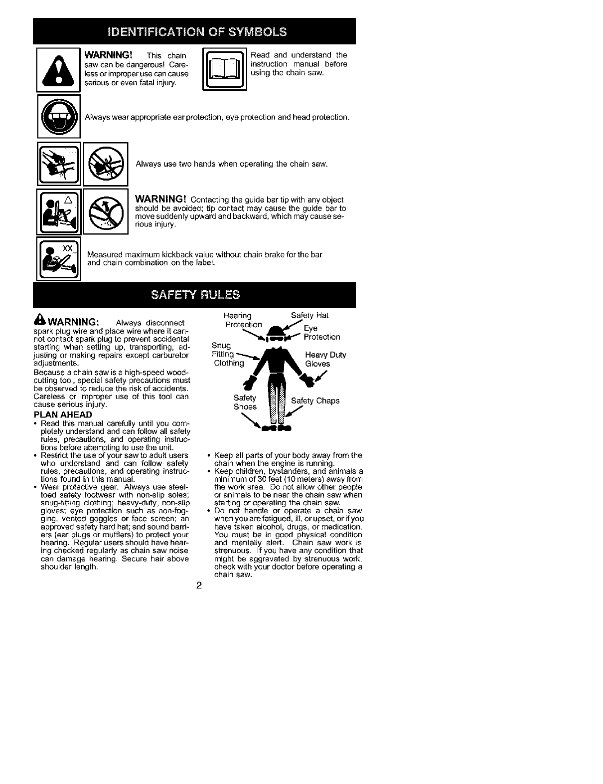
• Wear protective gear. Always use steel-
toed safety footwear with non-slip soles;
snug-fitting clothing; heavy-duty, non-slip
gloves; eye protection such as non-fog-
ging, vented goggles or face screen; an
approved safety hard hat; and sound barri-
ers (ear plugs or mufflers) to protect your
hearing. Regular users should have hear-
ing checked regularly as chain saw noise
can damage hearing. Secure hair above
shoulder length.
Hearing Safety Hat
Protection _'SEy e
"""_. t o,w _ "_" Protection
Snug
Heavy Duty
Clothing Gloves
Safety Safety Chaps
Shoes
2
• Keep all parts of your body away from the
chain when the engine is running.
• Keep children, bystanders, and animals a
minimum of 30 feet (1g meters) away from
the work area. Do not allow other people
or animals to be near the chain saw when
starting or operating the chain saw.
• Do not handle or operate a chain saw
when you are fatigued, ill, or upset, or ifyoe
have taken alcohol, drugs, or medication.
You must be in good physical condition
and mentally alert. Chain saw work is
strenuous. If you have any condition that
might be aggravated by strenuous work,
check with your doctor before operating a
chain saw.
• Carefullyplanyoursawingoperationinad-
vance.Donotstartcuttinguntilyouhavea
clearworkarea,securefooting,and,ifyou
arefellingtrees,aplannedretreatpath.
OPERATE YOUR SAW SAFELY
• Do not operate a chain saw with one hand.
Serious injury to the operator, helpers, by-
standers or any combination of these per-
sons may result from one-handed opera-
tion. A chain saw is intended for
two-handed use.
• Operate the chain saw only in a well-venti-
lated outdoor area.
• Do not operate saw from a ladder or in a
tree.
• Make sure the chain will not make contact
with any object while starting the engine.
Never try to start the saw when the guide
bar is in a cut.
• Do not put pressure on the saw at the end
of the cut. Applying pressure can cause
you to lose control when the cut is com-
pleted.
• Stop the engine before setting the saw
down.
• Do not operate a chain saw that is dam-
aged, improperly adjusted, or not com-
pletely and securely assembled. Always
replace bar, chain, hand guard, or chain
brake immediately if it becomes damaged,
broken or is otherwise removed.
• With the engine stopped, hand carry the
chain saw with the muffler away from your
body, and the guide bar and chain to the
rear, preferably covered with a scabbard.
MAINTAIN YOUR SAW IN GOOD
WORKING ORDER
• Have all chain saw service performed by a
qualified service dealer with the exception
of the items listed in the maintenance sec-
tion of this manual. Forexample, if improp-
er tools are used to remove or hold the fly-
wheel when servicing the clutch, structural
damage to the flywheel can occur and
cause the flywheel to burst.
• Make certain the saw chain stops moving
when the throttle trigger is released. For
correction, refer to CARBURETOR AD-
JUSTMENTS.
• Never modify your saw in any way.
• Keep the handles dry, clean, and free ofoil
or fuel mixture.
• Keep fuel and oil caps, screws, and fas-
teners securely tightened.
• Use only Poulan PRO_) accessories and
replacement parts as recommended.
HANDLE FUEL WITH CAUTION
• Do not smoke while handling fuel or while
operating the saw.
• Eliminate all sources of sparks or flame in
the areas where fuel is mixed or poured.
There should be no smoking, open flames,
or workthat could cause sparks. Allow en-
gine to cool before refueling.
• Mix and pour fuel in an outdoor area on
bare ground; store fuel in a cool, dry, well
ventilated place; and use an approved,
marked container for all fuel purposes.
Wipe up all fuel spills before starting saw.
• Move at least 10 feet (3 meters) from fuel-
ing site before starting engine.
• Turn the engine off and let saw cool in a
non-combustible area, not on dry leaves,
straw, paper, etc. Slowly remove fuel cap
and refuel unit.
• Store the unit and fuel in an area where fuel
vapors cannot reach sparks or open
flames from water heaters, electric motors
or switches, furnaces, etc.
KICKBACK
_,WARNING: Avoid kickback which
can result in serious injury. Kickback is the
backward, upward or sudden forward motion
of the guide bar occurring when the saw
chain near the upper tip of the guide bar con-
tacts any object such as a log or branch, or
when the wood closes in and pinches the
saw chain in the cut. Contacting a foreign ob-
ject in the wood can also result in loss of
chain saw control.
•Rotational Kickback can occur when the
moving chain contacts an object at the up-
per tip of the guide bar. This contact can
cause the chain to dig into the object,
which stops the chain for an instant. The
result is a lightning fast, reverse reaction
which kicks the guide bar up and back to-
ward the operator.
• Pinch-Kickback can occur when the the
wood closes in and pinches the moving
saw chain in the cut along the top of the
guide bar and the saw chain is suddenly
stopped. This sudden stopping of the
chain results in a reversal of the chain
force used to cut wood and causes the
saw to move in the opposite direction of the
chain rotation. The saw is driven straight
back toward the operator.
•Pull-In can occur when the moving chain
contacts a foreign object in the wood in the
cut along the bottom of the guide bar and the
saw chain is suddenly stopped. This sudden
stopping pulls the saw forward and away
from the operator and could easily cause the
operator to lose control of the saw.
Avoid Pinch-Kickback:
• Be extremely aware of situations or ob-
structions that can cause material to pinch
the top of or otherwise stop the chain.
• Do not cut more than one log at a time.
• Do not twist the saw as the bar is with-
drawn from an undercut when bucking.
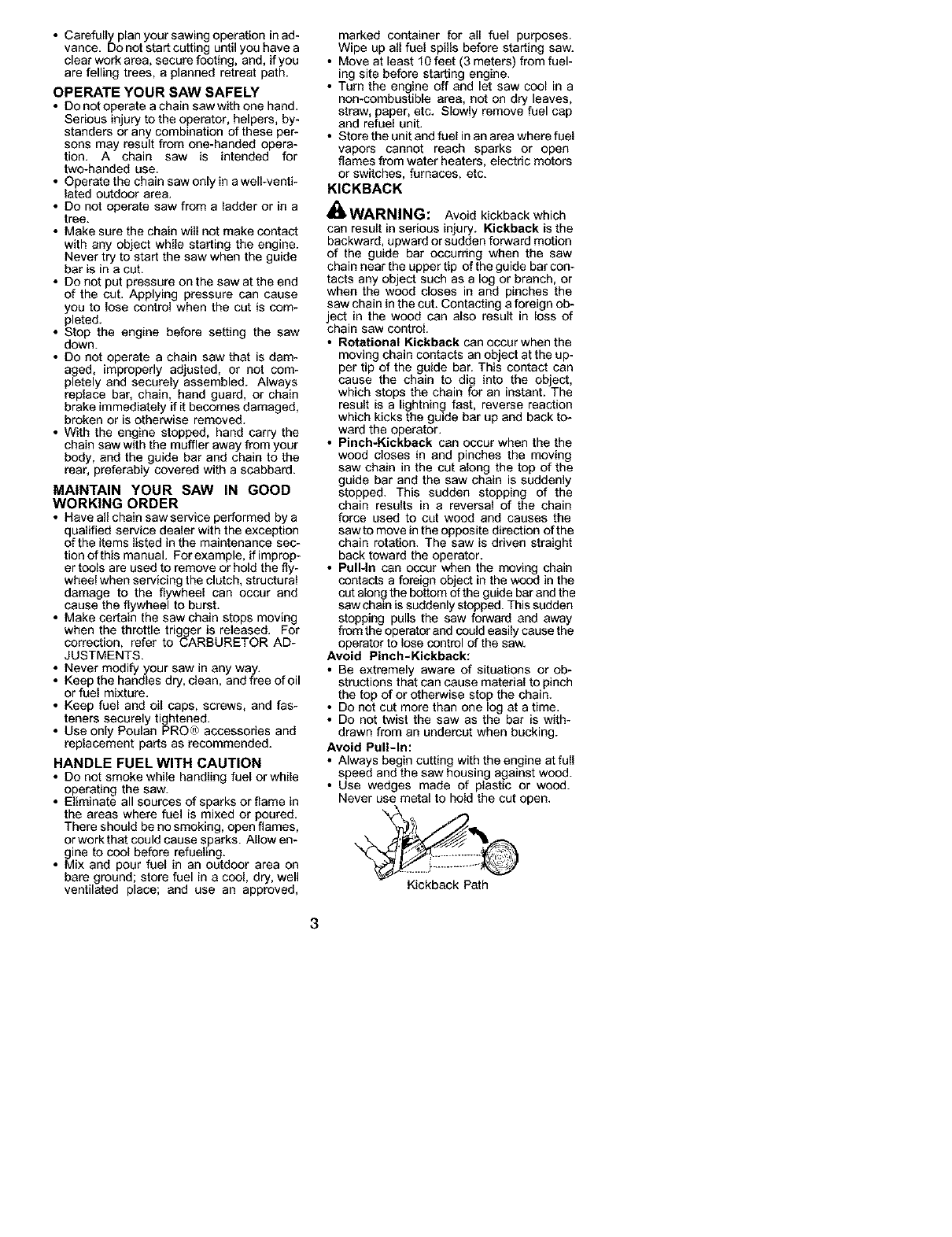
Avoid Pull-In:
• Always begin cutting with the engine at full
speed and the saw housing against wood.
• Use wedges made of plastic or wood.
Never use metal to hold the cut open.
Kickback Path
3
'_t Avoid Obstructions
Clear The Working Area
REDUCE THE CHANCE OF
KICKBACK
• Recognize that kickback can happen.
With a basic understanding of kickback,
you can reduce the element of surprise
which contributes to accidents.
• Never let the moving chain contact any ob-
ject at the tip of the guide bar.
• Keep the working area free from obstruc-
tions such as other trees, branches, rocks,
fences, stumps, etc. Eliminate or avoid
any obstruction that your saw chain could
hit while you are cutting. When cutting a
branch, do not let the guide bar contact
branch or other objects around it.
• Keep your saw chain sharp and properly
tensioned. A loose or dull chain can in-
crease the chance of kickback occurring.
Follow manufacturer's chain sharpening
and maintenance instructions. Check ten-
sion at regular intervals with the engine
stopped, never with the engine running.
Make sure the chain brake nuts are se-
curely tightened after tensioning the chain.
• Begin and continue cutting at full speed. If
the chain is moving at a slower speed,
there is greater chance of kickback occur-
ring.
• Cut one log at a time.
• Use extreme caution when re-entering a
previous cut.
• DO not attempt cuts starting with the tip of
the bar (plunge cuts).
• Watch for shifting logs or other forces that
could close a cut and pinch or fall into
chain.
• Use the Reduced-Kickback Guide Bar
and Low-Kickback Chain specified for
your saw.
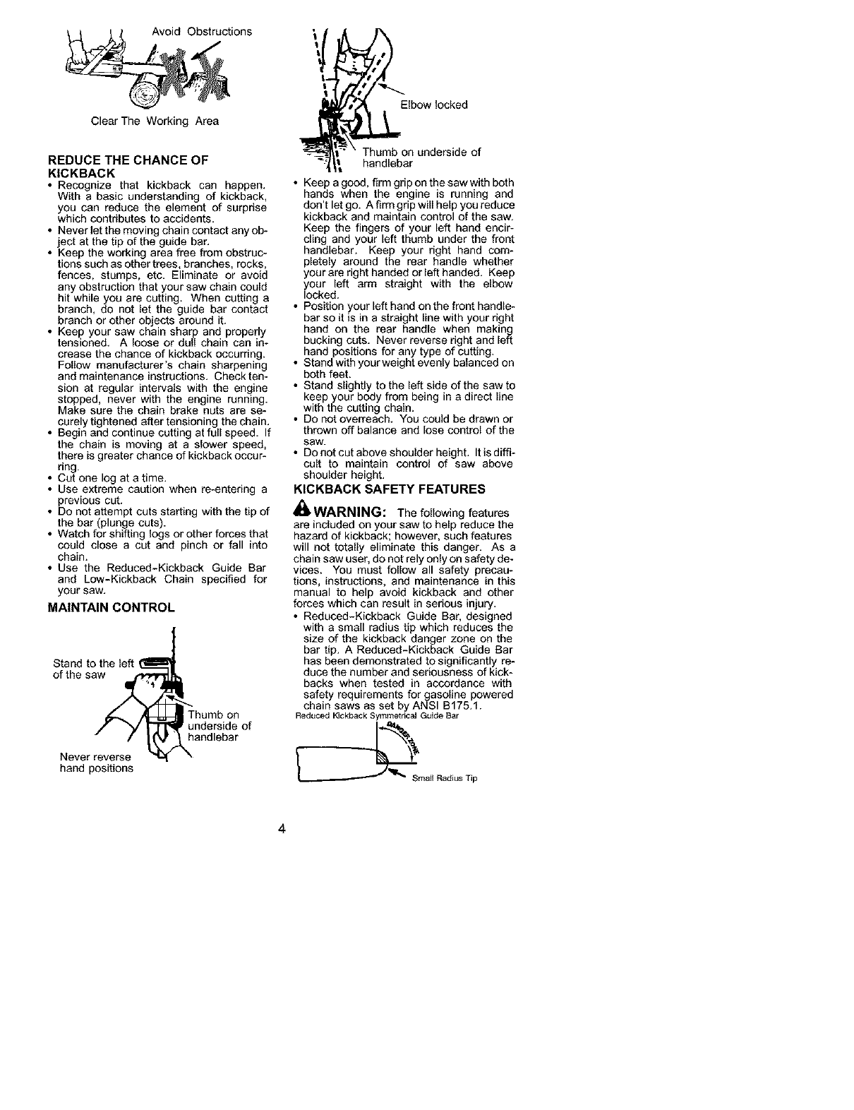
MAINTAIN CONTROL
Stand to the left
of the saw m_f._ a
Thumb on
underside of
handlebar
Never reverse \
hand positions
Elbow locked
Thumb on underside of
handlebar
• Keep a good, firm grip on the saw with both
hands when the engine is running and
don't let go. A firm grip will help you reduce
kickback and maintain control of the saw.
Keep the fingers of your left hand encir-
cling and your left thumb under the front
handlebar. Keep your right hand com-
pletely around the rear handle whether
your are right handed or left handed. Keep
your left arm straight with the elbow
looked.
• Position your left hand on the front handle-
bar so it is in a straight line with your right
hand on the rear handle when making
bucking cuts. Never reverse right and left
hand positions for any type of cutting.
• Stand with yoor weight evenly balanced on
both feet.
• Stand slightly to the left side of the saw to
keep your body from being in a direct line
with the cutting chain.
• Do not overreach. You could be drawn or
thrown off balance and lose control of the
saw.
• DOnot cut above shoulder height. It is diffi-
cult to maintain control of saw above
shoulder height.
KICKBACK SAFETY FEATURES
i_ WARNING: The following features
are included on your saw to help reduce the
hazard of kickback; however, such features
will not totally eliminate this danger. As a
chain saw user, do not rely only on safety de-
vices. You must follow all safety precau-
tions, instructions, and maintenance in this
manual to help avoid kickback and other
forces which can result in serious injury.
• Reduced-Kickback Guide Bar, designed
with a small radius tip which reduces the
size of the kickback danger zone on the
bar tip. A Reduced-Kickback Guide Bar
has been demonstrated to significantly re-
duce the number and seriousness of kick-
backs when tested in accordance with
safety requirements for gasoline powered
chain saws as set by ANSI B175.1.
Reduced Kickback Symmetrical Guide Bar
4
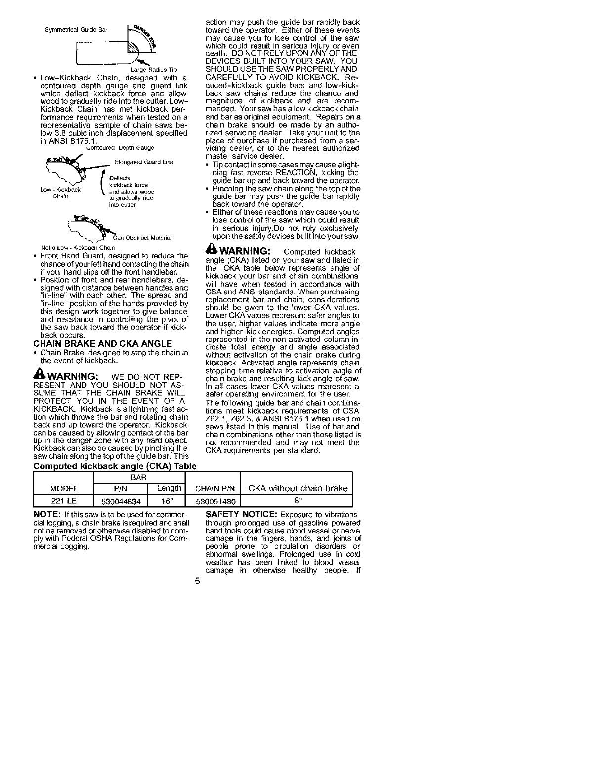
Symmetdca_ Guide Bar _114_
Large Radius Tip
• Low-Kickback Chain, designed with a
contoured depth gauge and guard link
which deflect kickback force and allow
wood to gradually ride into the cutter. Low-
Kickback Chain has met kickback per-
formance requirements when tested on a
representative sample of chain saws be-
low 3.8 cubic inch displacement specified
in ANSI B175.1.
Contoured Depth GaL_ge
_[k Elongated Guard LinkDeflects
ickback force
Low-Kickback and allows wood
Chain to gradually ride
into cutter
_L_an Obstruct M ateriaJ
Not a Low-Kickback Chain
• Front Hand Guard, designed to reduce the
chance of your left hand contacting the chain
if your hand slips off the front handlebar.
• Position of front and rear handlebars, de-
signed with distance between handles and
"in-line" with each other. The spread and
"in-line" position of the hands provided by
this design work together to give balance
and resistance in controlling the pivot of
the saw back toward the operator if kick-
back occurs.
CHAIN BRAKE AND CKA ANGLE
• Chain Brake, designed to stop the chain in
the event of kickback.
_,WARNING: WE DO NOT REP-
RESENT AND YOU SHOULD NOT AS-
SUME THAT THE CHAIN BRAKE WILL
PROTECT YOU IN THE EVENT OF A
KICKBACK. Kickback is a lightning fast ac-
tion which throws the bar ned rotating chain
back and up toward the operator. Kickback
can be caused by allowing contact of the bar
tip in the danger zone with any hard object.
Kickback can also be caused by pinching the
saw chain along the top of the guide bar. This
Computed kickback angle (CKA) Table
BAN
MODEL P/N Length
221 LE 530044834 16
NOTE: If this saw is to be used for commer-
cial logging, a chain brake is required and shall
not be removed or otherwise disabled to com-
ply with Federal OSHA Regulations for Com-
mercial Logging.
action may push the guide bar rapidly back
toward the operator. Either of these events
may cause you to lose control of the saw
which could result in serious injury or even
death. DO NOT RELY UPON ANY OF THE
DEVICES BUILT INTO YOUR SAW. YOU
SHOULD USE THE SAW PROPERLY AND
CAREFULLY TO AVOID KICKBACK. Re-
duced-kickback guide bars and low-kick-
back saw chains reduce the chance and
magnitude of kickback and are recom-
mended. Your saw has a low kickback chain
and bar as original equipment. Repairs on a
chain brake should be made by an autho-
rized servicing dealer. Take your unit to the
place of purchase if purchased from a ser-
vicing dealer, or to the nearest authorized
master service dealer.
• Tip contact in some cases may cause a light-
ning fast reverse REACTION, kicking the
guide bar up and back toward the operator.
• Pinching the saw chain along the top of the
guide bar may push the guide bar rapidly
back toward the operator.
• Either ofthese reactions maycauseyouto
lose control of the saw which could result
in serious injury.Do not rely exclusively
upon the safety devices built into your saw.
_WARNING: Computed kickback
angle (CKA) listed on your saw and listed in
the CKA table below represents angle of
kickback your bar and chain combinations
will have when tested in accordance with
CSA and ANSI standards. When purchasing
replacement bar and chain, considerations
should be given to the lower CKA values.
Lower CKA values represent safer angles to
the user, higher values indicate more angle
and higher kick energies. Computed angles
represented in the non-activated column in-
dicate total energy and angle associated
without activation of the chain brake during
kickback. Activated angle represents chain
stopping time relative to activation angle of
chain brake and resulting kick angle of saw.
In all cases lower CKA values represent a
safer operating environment for the user.
The following guide bar and chain combina-
tions meet kickback requirements of CSA
Z62.1, Z62.3, & ANSI B175.1 when used on
saws listed in this manual. Use of bar and
chain combinations other than those listed is
not recommended and may not meet the
CKA requirements per standard.
CHAIN P/N CKA without chain brake
530051480 8 °
SAFETY NOTICE: Exposure to vibrations
through prolonged use of gasoline powered
hand tools could cause blood vessel or nerve
damage in the fingers, hands, and joints of
people prone to circulation disorders or
abnormal swellings. Prolonged use in cold
weather has been linked to blood vessel
damage in otherwise healthy people. If
5
symptoms occur such as numbness, pain,
loss of strength, change in skin color or texture,
or loss of feeling inthe fingers, hands, or joints,
discontinue the use of this tool and seek
medical attention. An anti-vibration system
does not guarantee the avoidance of these
problems. Users who operate power tools on
a continual and regular basis must monitor
closely their physical condition and the
condition of this tool.
SPECIAL NOTICE: Your saw is equipped
with a temperature limiting muffler and spark
arresting screen which meets the
requirements of California Codes 4442 and
4443. All U.S. forest land and the states of
California, Idaho, Maine, Minnesota, New
Jersey, Oregon, and Washington require by
law that many internal combustion engines
to be equipped with a spark arresting screen.
If you operate a chain saw in a state or locale
where such regulations exist, you are legally
responsible for maintaining the operating
condition of these parts. Failure to do so is
a violation of the law. Refer to the SERVICE
section for maintenance of the spark
arresting screen.
Failure to follow all Safety Rules and Precau-
tions can result in serious injury. If situations
occur which are not covered in this manual,
use care and good judgement. If you need
assistance, contact your authorized service
dealer or call 1-800-554-6723.
STANDARDS: This saw is listed by Under-
writer's Laboratories, Inc., and the Canadian
Standards Association in accordance with:
ANSI B175.1-2000 American National
Standard for Powered Tools - Gasoline
Powered Chain Saw - Safety Requirements
CSA Z62.1-1995 Chain Saws - Occupa-
tional Health and Safety
CSA Z62.3-1996 Chain Saw Kickback Oc-
cupational Health and Safety
Protective gloves (not provided) should be
worn during assembly.
ATTACHING THE BAR & CHAIN (If not
already attached)
_ WARNING: If received assembled,
repeat all steps to ensure your saw is prop-
erly assembled and all fasteners are secure.
Always wear gloves when handling the
chain. The chain is sharp and can cut you
even when it is not movingt
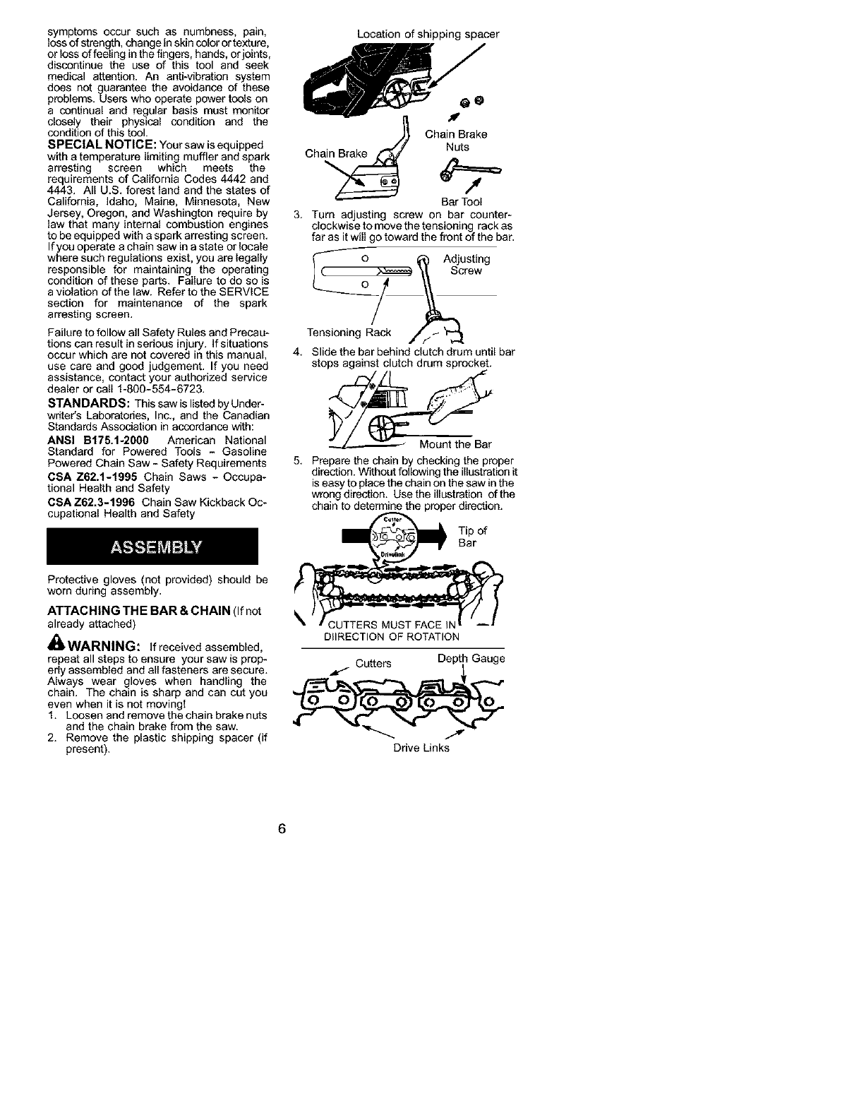
1. Loosen and remove the chain brake nuts
and the chain brake from the saw.
2. Remove the plastic shipping spacer (if
present).
Location of shipping spacer
chainBak
Ch Nuts
Bar Tool
3. Turn adjusting screw on bar counter-
clockwise to move the tensioning rack as
far as it will go toward the front of the bar.
° AdiU;e" g
Tensioning Rack //_ '_
4. Slide the bar behiod clutch drum until bar
stops against clutch drum sprocket.
5. Prepare the chain by checking the proper
direction. Without following the illustration it
is easy to place the chain on the saw in the
wrong direction. Usethe illustration ofthe
chain to determine the proper direction.
of
DIIRECTION OF ROTATION
Cutters Depl i Gauge
Drive Links
6
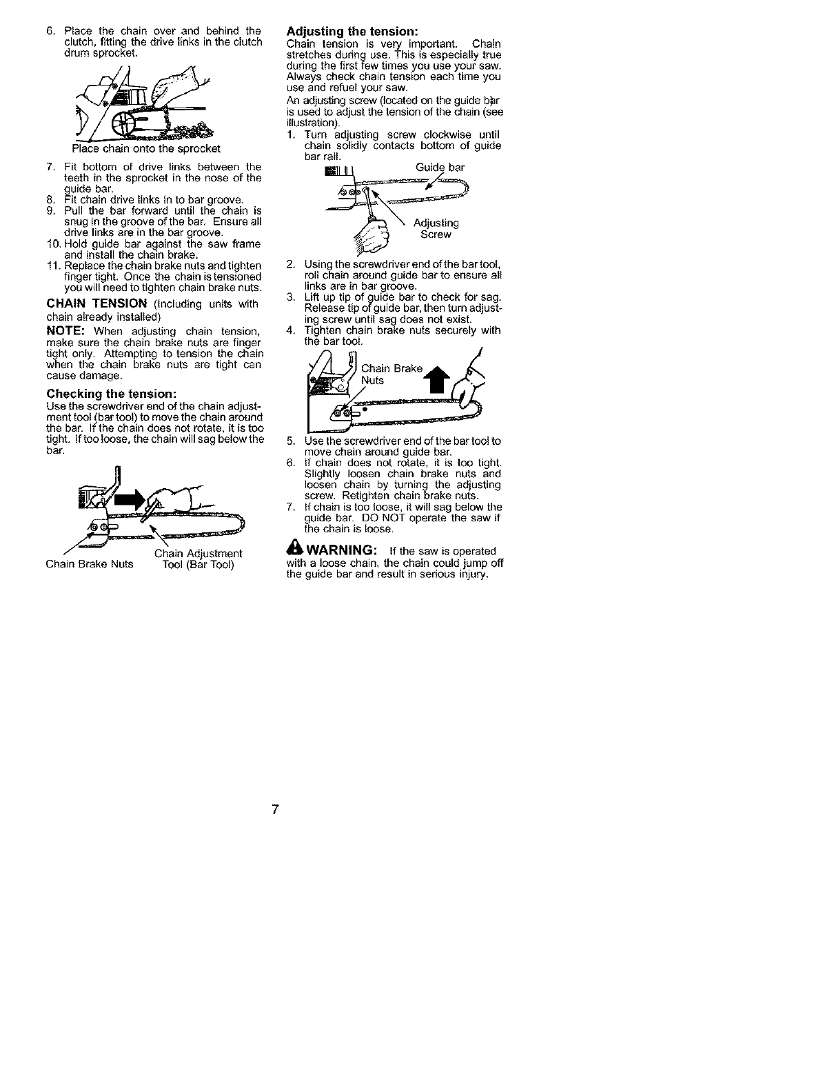
6. Place the chain over and behind the
clutch, fitting the drive links in the clutch
drum sprocket.
Place chain onto the sprocket
7. Fit bottom of drive links between the
teeth in the sprocket in the nose of the
guide bar.
8. Fit chain drive links in to bar groove.
9. Pull the bar forward until the chain is
snug in the groove of the bar. Ensure all
drive links are in the bar groove.
10. Hold guide bar against the saw frame
and install the chain brake.
11. Replace the chain brake nuts and tighten
finger tight. Once the chain is tensioned
you will need to tighten chain brake nuts.
CHAIN TENSION (Including units with
chain already installed)
NOTE: When adjusting chain tension,
make sure the chain brake nuts are finger
tight only. Attempting to tension the chain
when the chain brake nuts are tight can
cause damage.
Checking the tension:
Use the screwdriver end of the chain adjust-
ment tool (bar tool) to move the chain around
the bar. If the chain does not rotate, it is too
tight. If tooloose, the chain will sag below the
bar.
Chain Brake Nuts Tool (Bar Tool)
Adjusting the tension:
Chain tension is very important. Chain
stretches during use. This is especially true
during the first few times you use your saw.
Always check chain tension each time you
use and refuel your saw.
An adjusting screw (located on the guide b)ar
is used to adjust the tension of the chain (see
illustration).
1. Turn adjusting screw clockwise until
chain solidly contacts bottom of guide
bar rail.
2. Using the screwdriver end of the bar tool,
roll chain around guide bar to ensure all
links are in bar groove.
3. Lift up tip of guide bar to check for sag.
Release tip of guide bar, then turn adjust-
ing screw until sag does not exist.
4. Tighten chain brake nuts securely with
the bar tool.
Chain Brake
Nuts
5. Use the screwdriver end of the bar tool to
move chain around guide bar.
6. If chain does not rotate, it is too tight.
Slightly loosen chain brake nuts and
loosen chain by turning the adjusting
screw. Retighten chain brake nuts.
7. If chain is too loose, it will sag below the
guide bar. DO NOT operate the saw if
the chain is loose.
WARNING: If the saw is operated
with a loose chain, the chain could jump off
the guide bar and result in serious injury.
7
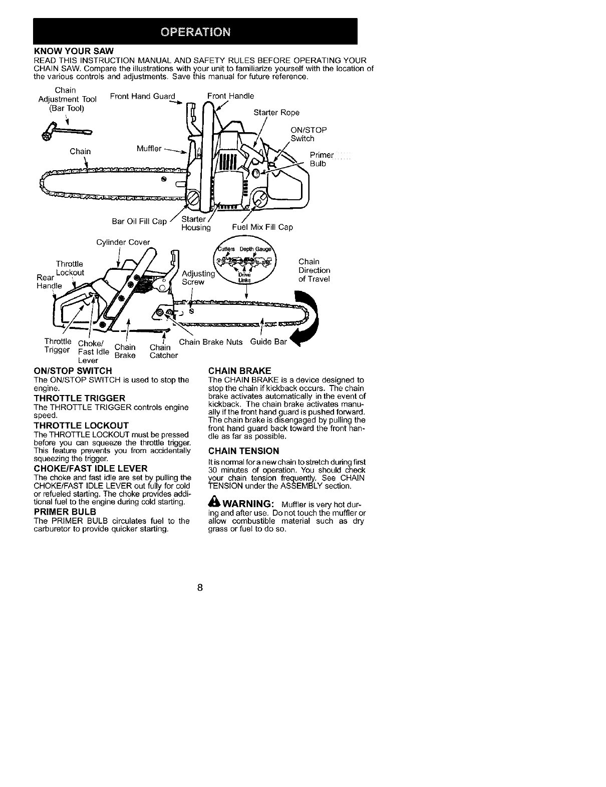
KNOW YOUR SAW
READ THIS INSTRUCTION MANUAL AND SAFETY RULES BEFORE OPERATING YOUR
CHAIN SAW. Compare the illustrations with your unit to familiarize yourself with the location of
the various controls and adjustments. Save this manual for future reference.
Chain
Adjustment Tool
(Bar Tool)
Chain Muffler
Throttle
Rear Lockout
Handle
Front Hand Guard Front Handle
Bar Oil Fill Cap/-_ c _
Housing Fuel Mix Fill Cap
Adjusting_
Screw
Cylinder Cover
Chain
Direction
of Travel
Throttle Choke/ Chain Chain Chain Brake Nuts Guide
Trigger Fast Idle Brake Catcher
Lever
ONISTOP SWITCH
The ON/STOP SWITCH is used to stop the
engine.
THROTTLE TRIGGER
The THROTTLE TRIGGER controls engine
speed.
THROTTLE LOCKOUT
The THROTTLE LOCKOUT must be pressed
before you can squeeze the throttle trigger.
This feature prevents you from accidentally
squeezing the trigger.
CHOKE/FAST IDLE LEVER
The choke and fast idle are set by pulling the
CHOKE/FAST IDLE LEVER out fully for cold
or refueled starting. The choke provides addi-
tional fuel to the engine during cold starting.
PRIMER BULB
The PRIMER BULB circulates fuel to the
carburetor to provide quicker starting.
CHAIN BRAKE
The CHAIN BRAKE is adevice designed to
stop the chain if kickback occurs. The chain
brake activates automatically in the event of
kickback. The chain brake activates manu-
ally if the front hand guard is pushed forward.
The chain brake is disengaged by pulling the
front hand guard back toward the front han-
dle as far as possible.
CHAIN TENSION
It is normal for a new chain to stretch during first
30 minL_es of operation. YOU should check
your chain tension frequently. See CHAIN
TENSION under the ASSEMBLY section.
A
dlIWARNING: Muffler is very hot dur-
ing and after use. Do not touch the muffler or
allow combustible material such as dry
grass or fuel to do so.
8
WARNING: Remove fuel cap slow-
ly when refueling.
FUELING ENGINE
This engine is certified to operate on
unleaded gasoline. Before operation,
gasoline must be mixed with a good quality
synthetic 2-cycle air-cooled engine oil
designed to be mixed at a ratio of 40:1.
Poulan/Weed Eater brand synthetic oil is
recommended. A 40:1 ratio is obtained by
mixing 3.2 ounces (95 ml) ofoil with I gallon (4
liters)of unleaded gasoline. Included withthis
saw is a 3.2 ounce container of Poulan/Weed
Eater brand synthetic oil. Pour the entire
contents of this container into f gallon of
gasoline to achieve the proper fuel mixture.
DO NOT USE automotive or boat oil. These
oils will cause engine damage. When mixing
fuel follow the instructions printed on the
container. Always read and follow the safety
rules listed under HANDLE FUEL WITH
CAUTION.
BAR AND CHAIN LUBRICATION
The bar and chain require continuous lubri-
cation. Lubrication is provided by the auto-
matic oiler system when the oil tank is kept
filled. Lack ofoil will quickly ruin the bar and
chain. Too little oil will cause overheating
shown by smoke coming from the chain and/
or discoloration of the bar.
In freezing weather oil will thicken, making it
necessary to thin bar and chain oil with a
small amount (5 to 10%) of #1 Diesel Fuel or
kerosene. Bar and chain oil must be free
flowing for the oil system to pump enough oil
for adequate lubrication.
Genuine Poulan or Pouian PRO® bar and
chain oil is recommended to protect your unit
against excessive wear from heat and
friction. Poulan orPoulan PRO® oil resists
high temperature thinning. If Poulan or
Poulan PRO® bar and chain oil is not
available, use a good grade SAE 30 oil.
• Never use waste oil for bar and chain lubri-
cation.
• Always stop the engine before removing
the oil cap.
IMPORTANT
Experience indicates that alcohol-blended
fuels (called gasohol or using ethanol or
methanol) can attract moisture which leads
to separation and formation of acids during
storage. Acidic gas can damage the fuel
system of an engine while in storage. To
avoid engine problems, the fuel system
should be emptied before storage for 30
days or longer. Drain the gas tank, start the
engine and let it run until the fuel lines and
carburetor are empty. Use fresh fuel next
season. See STORAGE section for addi-
tional information.
9
_WARNING: The chain must not
move when the engine runs at idle speed. If
the chain moves at idle speed refer to CAR-
BURETOR ADJUSTMENT within this
manual. Avoid contact with the muffler. Ahot
muffler can cause serious burns.
To stop the engine move the ON/STOP
switch to the STOP position.
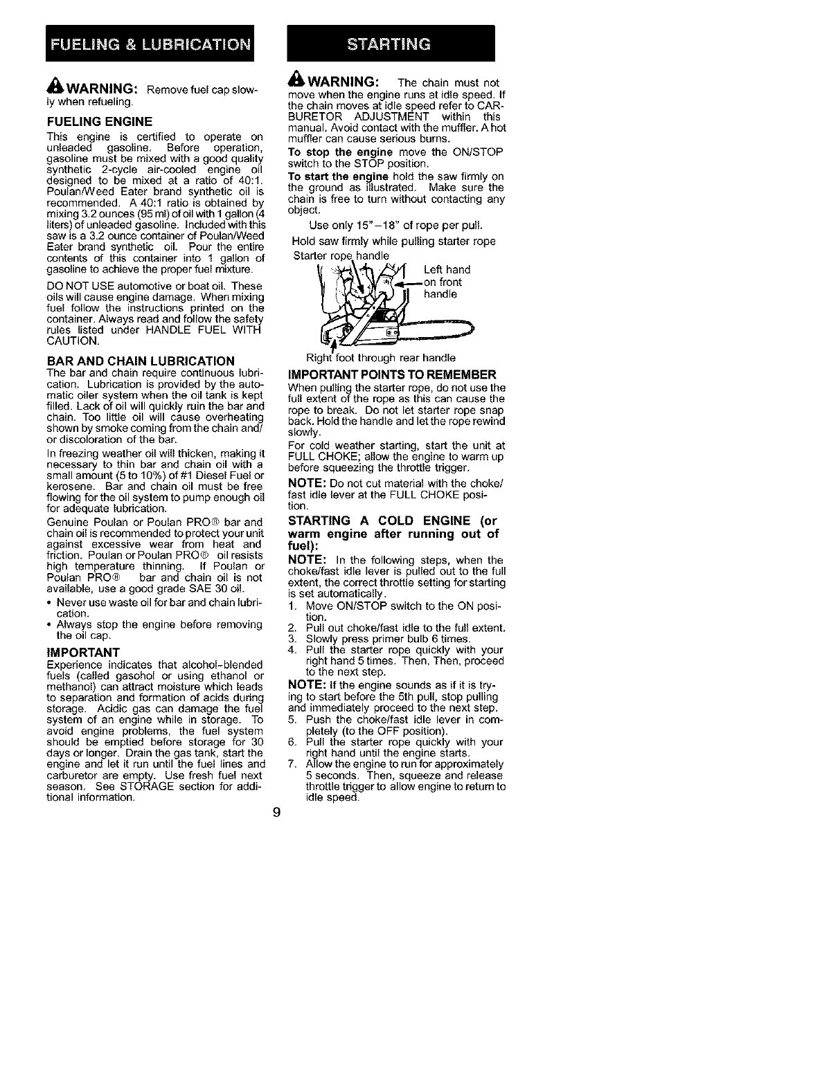
To start the engine hold the saw firmly on
the ground as illustrated. Make sure the
chain is free to turn without contacting any
object.
Use only 15"-18" of rope per pull.
Hold saw firmly while pulling starter rope
Starter rope handle
_"_\ _"_ '.L_ Left hand
_"{ _1,,_V '_,]',,_--- on front
Rig oot through rear handle
IMPI )RTANT POINTS TO REMEMBER
When pulling the starter rope, do not use the
full extent otthe rope as this can cause the
rope to break. Do not let starter rope snap
back, Hold the handle and let the rope rewind
slowly.
For cold weather starting, start the unit at
FULL CHOKE; allow the engine to warm up
before squeezing the throttle trigger.
NOTE: Do not cut material with the choke/
fast idle lever at the FULL CHOKE posi-
tion.
STARTING A COLD ENGINE (or
warm engine after running out of
fuel):
NOTE: In the following steps, when the
choke/fast idle lever is pulled out to the full
extent, the correct throttle setting for starting
is set automatically.
1. Move ON/STOP switch to the ON posi-
tion.
2. Pull out choke/fast idle to the full extent.
3. Slowly press primer bulb 6 times.
4. Pull the starter rope quickly with your
right hand 5 times. Then, Then, proceed
to the next step.
NOTE: If the engine sounds as if it is try-
ing to start before the 5th pull, stop pulling
and immediately proceed to the next step.
5. Push the choke/fast idle lever in com-
pletely (to the OFF position).
6. Pull the starter rope quickly with your
right hand until the engine starts.
7. Allow the engine to run for approximately
5 seconds. Then, squeeze and release
throttle trigger to allow engine to return to
idle speed.
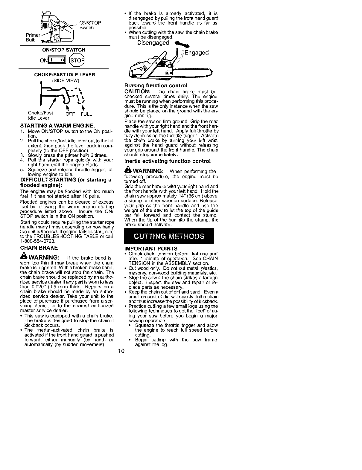
_ N/STOP
Switch
Primer
Bulb
CHOKE/FAST IDLE LEVER
.IEW)
Choke/Fast OFF FULL
Idle Lever
STARTING A WARM ENGINE:
1. Move ON/STOP switch to the ON posi-
tion.
2. Pull the choke/fast idle lever out to the full
extent, then push the lever back in com-
pletely (to the OFF position).
3. Slowly press the primer bulb 6 times.
4. Pull the starter rope quickly with your
right hand until the engine starts.
5. Squeeze and release throttle tdgger, al-
lowing engine to idle,
DIFFICULT STARTING (or starting a
flooded engine):
The engine may be flooded with toe much
fuel if it has not started after 10 pulls.
Flooded engines can be cleared of excess
fuel by following the warm engine starting
procedure listed above. Insure the ON/
STOP switch is in the ON position.
Starting could require pulling the starter rope
handle many times depending on how badly
the unit is flooded. If engine fails to start, refer
to the TROUBLESHOOTING TABLE or call
1-800-554-6723.
CHAIN BRAKE
_,WARNING: if the brake band is
worn too thin it may break when the chain
brake is triggered. With a broken brake band,
the chain brake will not stop the chain. The
chain brake should be replaced by an autho-
rized service dealer if any part is worn to less
than 0.020" (0.5 mm) thick. Repairs on a
chain brake should be made by an autho-
rized service dealer. Take your unit to the
place of purchase if purchased from a ser-
vicing dealer, or to the nearest authorized
master service dealer.
•This saw is equipped with a chain brake.
The brake is designed to stop the chain if
kickback occurs.
• The inertia-activated chain brake is
activated if the front hand guard is pushed
forward, either manually (by hand) or
automatically (by sudden movement).
• If the brake is already activated, it is
disengaged by pulling the front hand guard
back toward the front handle as far as
possible.
• When cutting with the saw, the chain brake
must be disengaged.
Disengaged __
_:ii_Engag ed
Braking function control
CAUTION: The chain brake must be
checked several times daily. The engine
must be running when performing this proce-
dure. This is the only instance when the saw
should be placed on the ground with the en-
gine running.
Place the saw on firm ground. Grip the rear
handle with your right hand and the front han-
dle with your left hand. Apply full throttle by
fully depressing the throttle trigger. Activate
the chain brake by turning your left wrist
against the hand guard without releasing
your grip around the front handle. The chain
should stop immediately.
Inertia activating function control
_WARNING: When performing the
following procedure, the engine must be
turned off.
Grip the rear handle with your right hand and
the front handle with your left hand. Hold the
chain saw approximately 14" (35 cm) above
a stump or other wooden surface. Release
your grip on the front handle and use the
weight of the saw to let the top of the guide
bar fall forward and contact the stump.
When the tip of the bar hits the stump, the
brake should activate.
IMPORTANT POINTS
• Check chain tension before first use and
after 1 minute of operation. See CHAIN
TENSION in the ASSEMBLY section.
• Cut wood only. Do not cut metal, plastics,
masonry, non-wood building materials, etc.
• Stop the saw if the chain strikes a foreign
object. Inspect the saw and repair or re-
place parts as necessary.
• Keep the chain OL_of dirt and sand. Even a
small amount of dirt will quickly dull a chain
and thus increase the possibility of kickback.
• Practice cutting a few small logs using the
following techniques to get the "feel" of us-
ing your saw before you begin a major
sawing operation.
• Squeeze the throttle trigger and allow
the engine to reach full speed before
cutting.
• Begin cutting with the saw frame
against the log.
10
• Keep the engine at full speed the entire
time you are cutting.
• Allow the chain to cut for you. Exert only
light downward pressure. If you force
the cut, damage to the bar, chain, oren-
gine can result.
• Release the throttle trigger as soon as
the cut is completed, allowing the en-
gine to idle. If you run the saw at full
throttle without a cutting load, unneces-
sary wear can occur to the chain, bar,
and engine. It is recommended that
the engine not be operated for lon-
ger than 30 seconds at full throttle.
• To avoid losing control when cut is com-
plete, do not put pressure on saw at end
of CL_.
• Stop the engine before setting the saw
down after cutting.
TREE FELLING TECHNIQUES
_WARNING: Check for broken or
dead branches which can fall while cutting
causing serious injury. Do not cut near build-
ings or electrical wires if you do not know the First cut
direction of tree fall, nor cut at night since you _.
will not be able to see well, nor during bad
weather such as rain, snow, or strong winds,
etc.
• Carefully plan your sawing operation in ad- Notch
vance,
• Clear the work area. You need a clear area
all around the tree so you can have secure
footing. Second/cut
• Study the natural conditions that can cause ._,__y.f_.,,,.-/
the tree to fall in a padicular direction.
Natural conditions that can cause a tree to • After removir
fall in a particular direction include:
• The wind direction and speed.
• The lean of the tree. The lean of a tree
might not be apparent due to uneven or
sloping terrain. Use a plumb or level to de-
termine the direction of tree lean.
• Weight and branches on one side.
• Surrounding trees and obstacles.
Look for decay and rot If the trunk is rotted, it
can snap and fall toward the operator. Check
for broken or dead branches which can fall on
you while CL_ting.
Make sure there is enough room for the tree to
fall. Maintain a distance of 2-1/2tree lengths
from the nearest person or other objects. En-
gine noise can drown OL_a warning call.
Remove dirt, stones, loose bark, nails, staples,
and wire from the tree where cuts are to be
made. Closing of
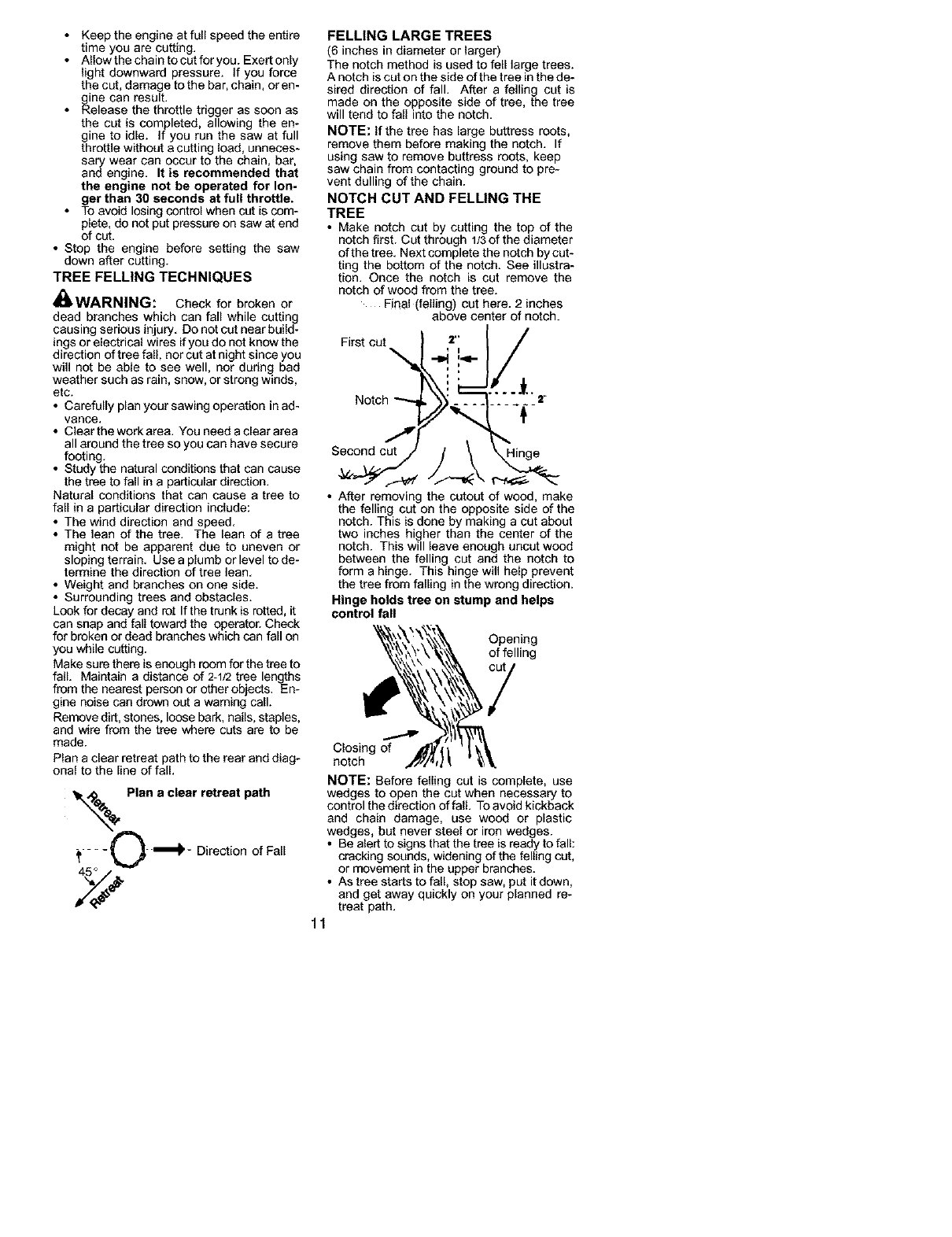
Plan a clear retreat path to the rear and diag- notch
onal to the line of fall.
_,_, Plan a clear retreat path
%
;_.... 0"_'- Direction of Fall
FELLING LARGE TREES
(6 inches in diameter or larger)
The notch method is used to fell large trees.
A notch is cut on the side of the tree inthe de-
sired direction of fall. After a felling cut is
made on the opposite side of tree, the tree
will tend to fall into the notch.
NOTE: If the tree has large buttress roots,
remove them before making the notch. If
using saw to remove buttress roots, keep
saw chain from contacting ground to pre-
vent dulling of the chain.
NOTCH CUT AND FELLING THE
TREE
• Make notch cut by cutting the top of the
notch first. Cut through 1/3 of the diameter
of the tree. Next complete the notch by cut-
ting the bottom of the notch. See illustra-
tion. Once the notch is cut remove the
notch of wood from the tree.
Final (felling) cut here. 2 inches
above center of notch.
the cutout of weed, make
the felling cut on the opposite side of the
notch. This is done by making a cut about
two inches higher than the center of the
notch. This will leave enough uncut wood
between the felling cut and the notch to
form a hinge. This hinge will help prevent
the tree from falling in the wrong direction.
Hinge holds tree on stump and helps
control fall
Opening
of felling
NOTE: Before felling cut is complete, use
wedges to open the cut when necessary to
control the direction of fall. To avoid kickback
and chain damage, use wood or plastic
wedges, but never steel or iron wedges.
• Be alert to signs that the tree is ready to fall:
cracking sounds, widening of the felling cut,
or movement in the upper branches.
• As tree starts to fall, stop saw, put it down,
and get away quickly on your planned re-
treat path.
11
• DO NOT cut down a partially fallen tree
with your saw. Be extremely cautious with
partially fallen trees that may be poorly
supported. When e tree doesn't fall com-
pletely, set the saw aside and pull down the
tree with acable winch, block and tackle,
or tractor.
CUTTING A FALLEN TREE
(BUCKING)
Bucking is the term used for cutting a fallen
tree to the desired log size.
WARNING: Do not stand on the log
being cut. Any portion can roll causing loss
of footing and control. Do not stand downhill
of the log being cut.
IMPORTANT POINTS
• Cut only one log at a time.
• CL_ shattered wood very carefully; sharp
pieces of wood could be flung toward opera-
to_
• Use a sawhorse to cut small logs. Never
allow another person to hold the log while
cutting and never hold the log with your leg
or foot.
• Do not cut in an area where logs, limbs,
and roots are tangled such as in a blown
down area. Drag the logs into a clear area
before cutting by pulling out exposed and
cleared logs first.
TYPES OF CUTTING USED FOR
BUCKING
_WARNING: If saw becomes
pinched or hung in a log, don't try to force it
out. You can lose control of the saw resulfing
in injury and/or damage tothe saw. Stop the
saw, drive a wedge of plastic or wood into the
cut until the saw can be removed easily. Re-
start the saw and carefully reenter the cut. To
avoid kickback and chain damage, do not
use a metal wedge. Do not attempt to restart
your saw when it is pinched or hung in a log.
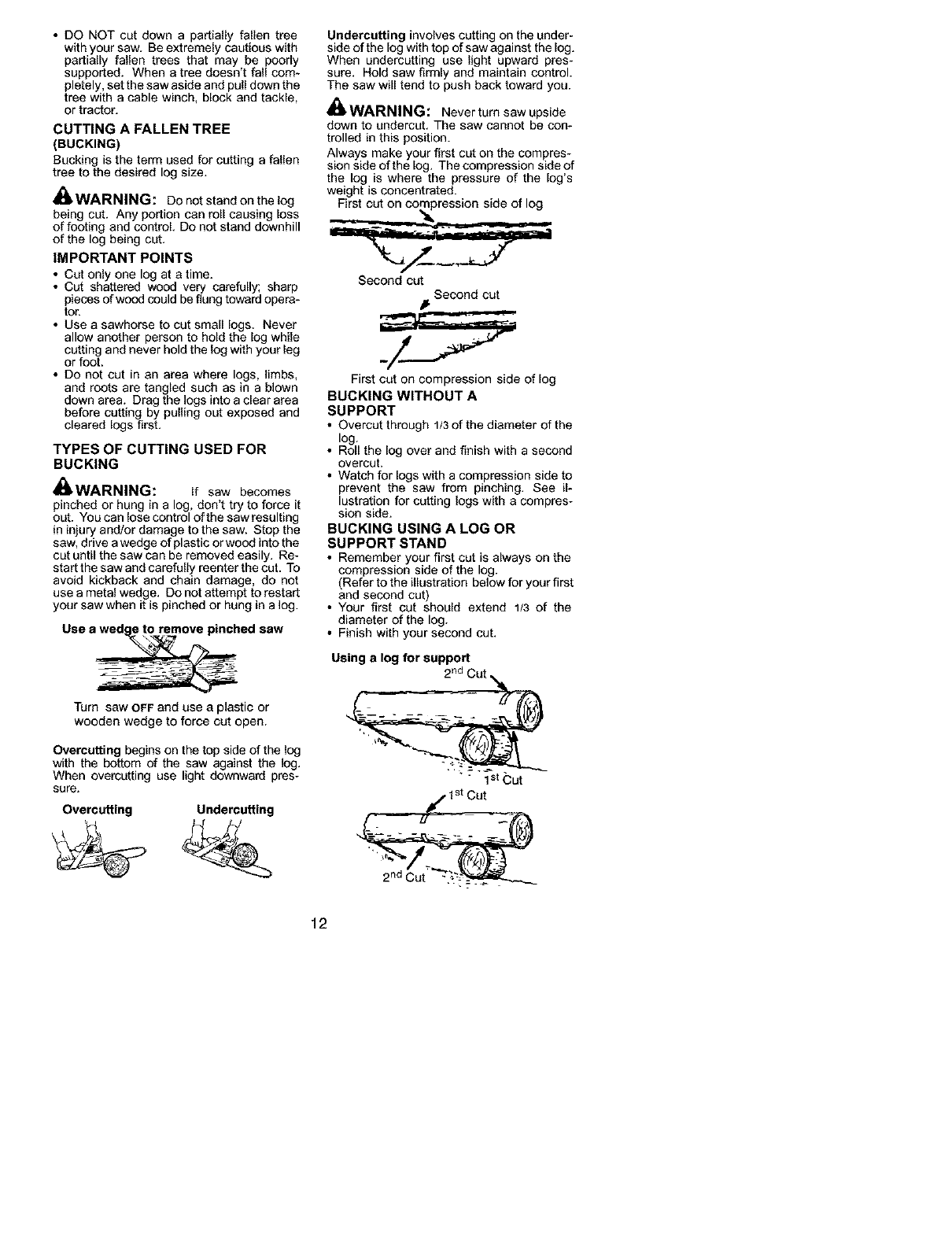
Use a wedge to remove pinched saw
Turn saw OFF and use a plastic or
wooden wedge to force cut open.
Overcutting begins on the top side of the log
with the bottom of the saw against the log.
When overcu_ting use light downward pres-
sure,
Overcutting Undercutting
Undercutting involves cutting on the under-
side of the log with top of saw against the log.
When undercutting use light upward pres-
sure. Hold saw firmly and maintain control.
The saw will tend to push back toward you.
_WARNING: Neverturnsawupside
down to undercut. The saw cannot be con-
trolled in this position.
Always make your first cut on the compres-
sion side of the log. The compression side of
the log is where the pressure of the log's
weight is concentrated.
First cut on compression side of log
Second cut
Second cut
First cut on compression side of log
BUCKING WITHOUT A
SUPPORT
• Overcut through 1/3 of the diameter of the
log.
• Roll the log over and finish with a second
overcut.
• Watch for logs with a compression side to
prevent the saw from pinching. See il-
lustration for cutting logs with a compres-
sion side.
BUCKING USING ALOG OR
SUPPORT STAND
• Remember your first cut is always on the
compression side of the log.
(Refer to the illustration below for your first
end second cut)
• Your first cut should extend 1/3 of the
diameter of the log.
• Finish with your second cut.
Using a log for support
2rid
12
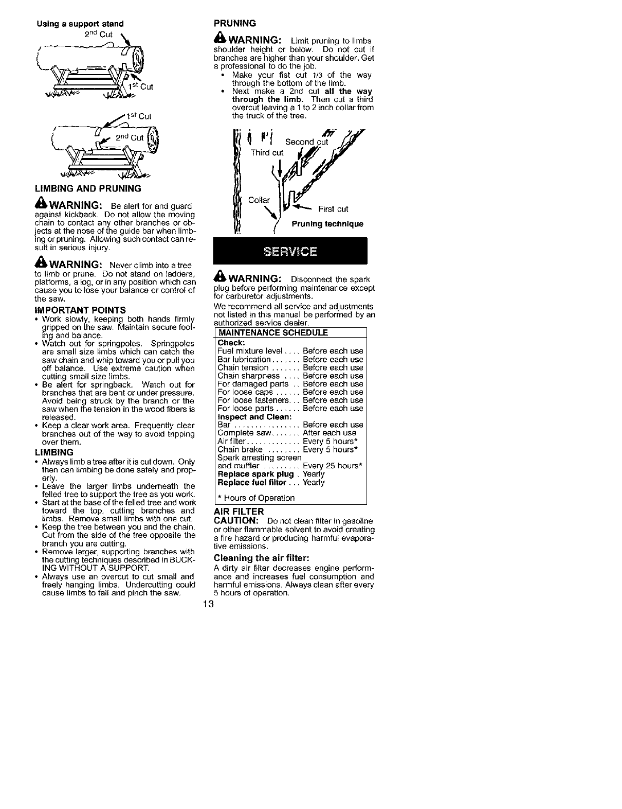
Using a support stand
2ndCut
1st Cut
/
2 nd Cut
LIMBING AND PRUNING
_,WARNING: Be alert for and guard
against kickback. Do not allow the moving
chain to contact any other branches or ob-
jects at the nose of the guide bar when limb-
log or pruning. Allowing such contact can re-
sult in serious injury.
WARNING: Never climb into a tree
to limb or prune. Do not stand on ladders,
platforms, a log, or in any position which can
cause you to lose your balance or control of
the saw.
IMPORTANT POINTS
• Work slowly, keeping both hands firmly
gripped on the saw. Maintain secure foot-
ing and balance.
• Watch out for springpoles. Springpoles
are small size limbs which can catch the
saw chain and whip toward you or pull you
off balance. Use extreme caution when
cutting small size limbs,
• Be alert for springback. Watch out for
branches that are bent or under pressure,
Avoid being struck by the branch or the
saw when the tension in the wood fibers is
released.
• Keep a clear work area, Frequently clear
branches out of the way to avoid tripping
over them.
LIMBING
• Always limb a tree after it is cut down. Only
then can Iimbing be done safely and prop-
erly.
• Leave the larger limbs underneath the
felled tree to support the tree as you work.
• Start at the base of the felled tree and work
toward the top, cutting branches and
limbs. Remove small limbs with one cut.
• Keep the tree between you and the chain.
Cut from the side of the tree opposite the
branch you are cutting.
• Remove larger, supporting branches with
the cutting techniques described in BUCK-
ING WITHOUT A SUPPORT.
• Always use an overcut to cut small and
freely hanging limbs. Undercuttiog could
cause limbs to fall and pinch the saw.
PRUNING
WARNING: Limit pruning to limbs
shoulder height or below. Do not cut if
branches are higher than your shoulder. Get
a professional to do the job.
• Make your fist cut 1/3 of the way
through the bottom of the limb.
• Next make a 2nd cut all the way
through the limb. Then cut a third
overcut leaving a 1 to 2 inch collar from
the truck of the tree.
_Th_Idic Second cut'_ZY'!t
Collar tit_/
_JV _ First cut
fPruning technique
_WARNING: Disconnect the spark
fPolUgbefore performing maintenance except
r carburetor adjustments.
We recommend all service and adjustments
not listed in this manual be performed by an
authorized service dealer.
MAINTENANCE SCHEDULE
Check:
Fuel mixture level ....
Bar lubrication .....
Chain tension .....
Chain sharpness ,,
For damaged parts
For loose caps ....
For loose fasteners,
For loose parts ....
Inspect and Clean:
Bar ................
Complete saw .......
Air filter .............
Before each use
Before each use
Before each use
Before each use
Before each use
Before each use
Before each use
Before each use
Before each use
After each use
Every 5 hours*
Chain brake ........ Every 5 hours*
Spark arresting screen
and muffler ......... Every 25 hours*
Replace spark plug , Yearly
Replace fuel filter,., Yearly
*Hours of Operation
AIR FILTER
CAUTION: Do not clean filter in gasoline
or other flammable solvent to avoid creating
a fire hazard or producing harmful evapora-
tive emissions.
Cleaning the air filter:
A dirty air filter decreases engine perform-
ance and increases fuel consumption and
harmful emissions. Always clean after every
5 hours of operation.
13
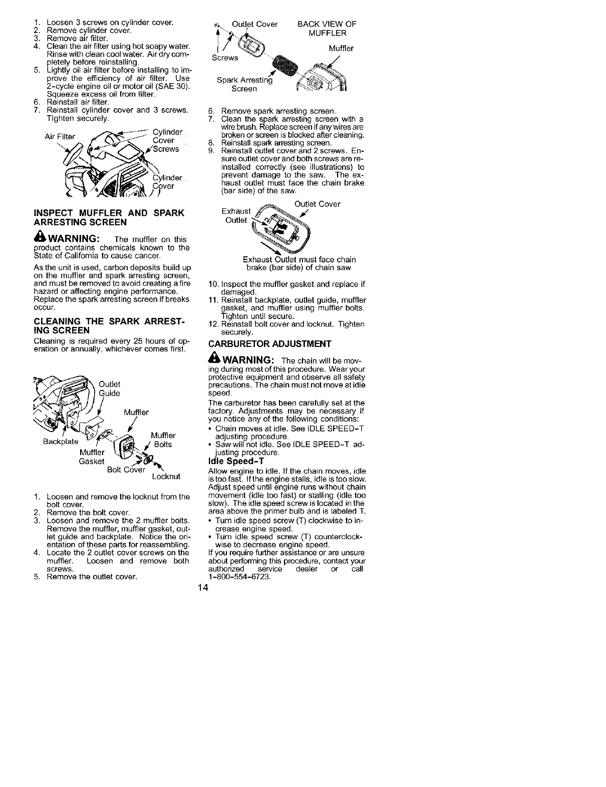
1. Loosen 3 screws on cylinder cover. _= Outlet Cover
2. Remove cylinder cover, A
3. Remove air filter,
4. Clean the air filter using hot soapy water,
Rinse with clean cool water. Air dry com- Screws
pletely before reinstalling.
5. Lightly oil air filter before installing to im-
prove the efficiency of air filter. Use Spark Arrestin:
2-cycle engine oil or motor oil (SAE 30). Screen
Squeeze excess oil from filter.
6. Reinstall air filter.
7. Reinstall cylinder cover and 3 screws.
Tighten securely.
Cylinder
Air Filter Cover
\
Cylinder
Cover
JJ
INSPECT MUFFLER AND SPARK
ARRESTING SCREEN
_,WARNING: The muffler on this
product contains chemicals known to the
State of California to cause cancer.
As the unit is used, carbon deposits build up
on the muffler and spark arresting screen,
and must be removed to avoid creating a fire
hazard or affecting engine performance.
Replace the spark arresting screen if breaks
occur.
CLEANING THE SPARK ARREST-
ING SCREEN
Cleaningisrequiredevery 25houre of op-
eration or annually, whichever comes first.
Outlet
Guide
Locknut
1. Loosen and remove the Iocknut from the
bolt cover.
2. Remove the bolt cover.
3. Loosen and remove the 2 muffler bolts.
Remove the muffler, muffler gasket, out-
let guide and backplate. Notice the ori-
entation of these parts for reassembling.
4. Locate the 2 outlet cover screws on the
muffler. Loosen and remove both
screws.
5. Remove the outlet cover.
BACK VIEW OF
MUFFLER
Muffler
6. Remove spark arresting screen.
7. Clean the spark arresting screen with a
wire brush. Replace screen if any wires are
broken or screen is blocked after cleaning.
8. Reinstall spark arresting screen.
9. Reinstall outlet cover and 2 screws. En-
sure outlet cover and both screws are re-
installed correctly (see illustrations) to
prevent damage to the saw. The ex-
haust outlet must face the chain brake
(bar side) of the saw.
Outlet Cover
Exhaust _ _ _€"
Outlet _'_
Exhaust Outlet must face chain
brake (bar side) of chain saw
10. Inspect the muffler gasket and replace if
damaged.
11. Reinstall backplate, outlet guide, muffler
gasket, and muffler using muffler bolts.
Tighten until secure.
12. Reinstall bolt cover and Iocknut. Tighten
securely.
CARBURETOR ADJUSTMENT
_WARNING: The chain will be mov-
ing during most of this procedure. Wear your
protective equipment and observe all safety
precautions. The chain must not move at idle
speed.
The carburetor has been carefully set at the
factory. Adjustments may be necessary if
you notice any of the following conditions:
• Chain moves at idle. See IDLE SPEED-T
adjusting procedure.
• Saw will not idle. See IDLE SPEED-T ad-
justing procedure.
Idle Speed-T
Allow engine to idle. ffthe chain moves, idle
istoo fast. If the engine stalls, idle is too slow.
Adjust speed until engine runs without chain
movement (idle too fast) or stalling (idle too
slow). The idle speed screw is located in the
area above the primer bulb and is labeled T.
• Turn idle speed screw (T) clockwise to in-
crease engine speed.
• Turn idle speed screw (T) counterclock-
wise to decrease engine speed.
If you require further assistance or are unsure
aboL_ performing this procedure, contact your
aL_horized service dealer or call
1-800-554-6723.
14
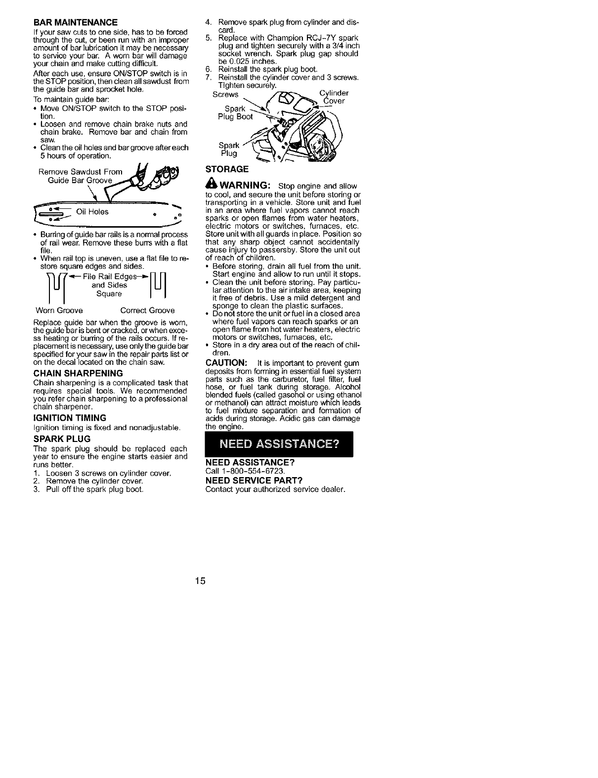
BAR MAINTENANCE
If your sew cuts to one side, has to be forced
through the cut, or been run with an improper
amount of bar lubrication it may be necessary
to service your bar. A worn bar will damage
your chain and make cutting difficult.
After each use, ensure ON/STOP switch is in
the STOP position, then clean all sawdust from
the guide bar and sprocket hole.
To maintain guide bar:
• Move ON/STOP switch to the STOP posi-
tion.
• Loosen end remove chain brake nL_Sand
chain brake. Remove bar and chain from
saw.
• Clean the oil holes and bargroove after each
5 hours of operation.
Remove Sawdust From _J_ Ji_
H
Guide Bar _oo_
Oil Holes , oQ
• Burring of guide bar rails is a normal process
of rail wear. Remove these burrs with a fiat
file.
• When rail top is uneven, use a fiat file to re-
store square edges end sides.
-_-FileRailEdges_-N N
and Sides I U I
Square I I
Worn Groove Correct Groove
Replace guide bar when the groove is worn,
the guide bar is bent or cracked, or when exce-
ss heating or burring of the rails occurs. If re-
placement is necessary, use only the guide bar
specified for your saw in the repair parts list or
on the decal located on the chain saw.
CHAIN SHARPENING
Chain sharpening is a complicated task that
requires special tools. We recommended
you refer chain sharpening to a professional
chain sharpener.
IGNITION TIMING
Ignition timing is fixed and nonadjustable.
SPARK PLUG
The spark plug should be replaced each
year to ensure the engine starts easier and
runs better.
1. Loosen 3 screws on cylinder cover.
2. Remove the cylinder cover.
3. Pull off the spark plug boot.
4. Remove spark plug from cylinder and dis-
card.
5. Replace with Champion RCJ-7Y spark
plug and tighten securely with a 3/4 inch
socket wrench. Spark plug gap should
be 0.025 inches.
6. Reinstall the spark plug boot.
7. Reinstall the cylinder cover and 3 screws.
Tighten securely.
Screws Cover
Plug Boot
Spark
Plug
STORAGE
i_ WARNING: Stop engine aed allow
to cool, and secure the unit before storing or
transporting in a vehicle. Store unit and fuel
in an area where fuel vapors cannot reach
sparks or open flames from water heaters,
electric motors or switches, furnaces, etc.
Store unit with all guards in place. Position so
that any sharp object cannot accidentally
cause injury to passersby. Store the unit out
of reach of children.
• Before storing, drain all fuel from the unit.
Start engine and allow to run until it stops.
• Clean the unit before storing. Pay particu-
lar attention to the air intake area, keeping
it free of debris. Use a mild detergent and
sponge to clean the plastic surfaces.
• Do not store the unit or fuel in a closed area
where fuel vapors can reach sparks or an
open flame from hot water heaters, electric
motors or switches, furnaces, etc.
• Store in a dry area out of the reach of chil-
dren.
CAUTION: It is important to prevent gum
deposits from forming in essential fuel system
parts such as the carburetor, fuel filter, fuel
hose, or fuel tank during storage. Alcohol
blended fuels (celled gasohol or using ethanol
or methanol) can attract moisture which leads
to fuel mixture separation and formation of
acids during storage. Acidic gas can damage
the engine.
NEED ASSISTANCE?
Call 1-800-554-6723.
NEED SERVICE PART?
Contact your authorized service dealer.
15
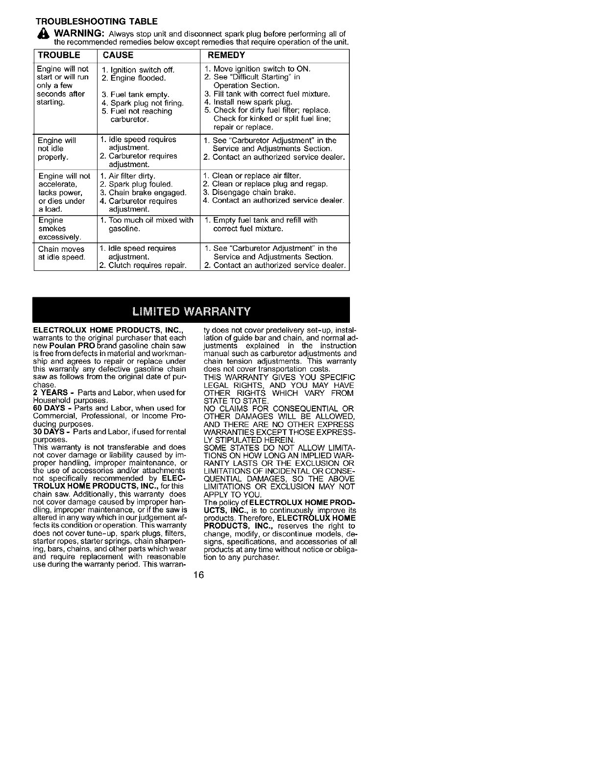
TROUBLESHOOTING TABLE
_, WARNING: Always stop unit and disconnect spark plug before performing all of
the recommended remedies below except remedies that require operation of the unit.
TROUBLE CAUSE REMEDY
Engine will not 1. Ignition switch off. 1. Move ignition switch to ON.
start or will run 2. Engine flooded. 2. See "Difficult Starting" in
only a few Operation Section.
seconds after 3. Fuel tank empty. 3. Fill tank with correct fuel mixture.
starting. 4. Spark plug not firing. 4. InstaU new spark plug.
5. Fuel not reaching 5. Check for dirty fuel filter; replace.
carburetor. Check for kinked or split fuel line;
repair or replace.
Engine will 1. Idle speed requires 1. See "Carburetor Adjustment" in the
not idle adjustment. Service and Adjustments Section.
properly. 2. Carburetor requires 2. Contact an authorized service dealer.
adjustment.
Engine will not 1. Air filter dirty. 1. Clean or replace air filter.
accelerate, 2. Spark plug fouled. 2. Clean or replace plug and regap.
lacks power, 3. Chain brake engaged. 3. Disengage chain brake.
or dies under 4. Carburetor requires 4. Contact an authorized service dealer.
a load. adjustment.
Engine 1. Too much oil mixed with 1. Empty fuel tank and refill with
smokes gasoline, correct fuel mixture.
excessively.
Chain moves 1. Idle speed requires 1. See "Carburetor Adjustment" in the
at idle speed, adjustment. Service and Adjustments Section.
2. Clutch requires repair. 2. Contact an authorized service dealer.
ELECTROLUX HOME PRODUCTS, INC.,
warrants to the original purchaser that each
new Poulan PRO brand gasoline chain saw
is free from defects in material and workman-
ship and agrees to repair or replace under
this warranty any defective gasoline chain
saw as follows from the original date of pur-
chase.
2YEARS - Parts and Labor, when used for
Household purposes.
60 DAYS - Parts and Labor, when used for
Commercial, Professional, or Income Pro-
ducing purposes.
30 DAYS - Parts and Labor, if used for rental
purposes.
This warranty is not transferable and does
not cover damage or liability caused by im-
proper handling, improper maintenance, or
the use of accessories and/or attachments
not specifically recommended by ELEC-
TROLUX HOME PRODUCTS, INC., for this
chain saw. Additionally, this warranty does
not cover damage caused by improper han-
dling, improper maintenance, or if the saw is
altered in any way which in our judgement af-
fects itscondition or operation. This warranty
does not cover tune-up, spark plugs, filters,
starter ropes, starter springs, chain sharpen-
ing, bars, chains, and other parts which wear
and require replacement with reasonable
use during the warranty pedod. This warran-
ty does not cover predelivery set-up, instal-
lation of guide bar and chain, and normal ad-
justments explained in the instruction
manual such as carburetor adjustments and
chain tension adjustments. This warranty
does not cover transportation costs.
THIS WARRANTY GIVES YOU SPECIFIC
LEGAL RIGHTS, AND YOU MAY HAVE
OTHER RIGHTS WHICH VARY FROM
STATE TO STATE.
NO CLAIMS FOR CONSEQUENTIAL OR
OTHER DAMAGES WILL BE ALLOWED,
AND THERE ARE NO OTHER EXPRESS
WARRANTIES EXCEPT THOSE EXPRESS-
LY STIPULATED HEREIN.
SOME STATES DO NOT ALLOW LIMITA-
TIONS ON HOW LONG AN IMPLIED WAR-
PANTY LASTS OR THE EXCLUSION OR
LIMITATIONS OF INCIDENTAL OR CONSE-
QUENTIAL DAMAGES, SO THE ABOVE
LIMITATIONS OR EXCLUSION MAY NOT
APPLY TO YOU.
The policy of ELECTROLUX HOME PROD-
UCTS, INC., is to continuously improve its
products. Therefore, ELECTROLUX HOME
PRODUCTS, INC., reserves the right to
change, modify, or discontinue models, de-
signs, specifications, and accessories of all
products at any time without notice or obliga-
tion to any purchaser.
16
YOUR WARRANTY RIGHTS AND OBLIGA-
TIONS: The U.S. Environmental Protection
Agency, California Air Resources Board, Envi-
ronment Canada and ELECTROLUX HOME
PRODUCTS, INC., are pleased to explain the
emissions control system warranty on your
year 2002-2004 small off-roed engine. In Cali-
fornia, all new small off-road engines must be
designed, built, and equipped to meet the
State's stringent anti-smog standards. ELEC-
TROLUX HOME PRODUCTS, INC., must
warrant the emission control system on your
small off-road engine for the periods of time
listed below provided there has been no abuse,
neglect, or improper maintenance of your small
off-road engine engine. Your emission control
system includes parts such as the carburetor
and the ignition system. Where a warrantable
condition exists, ELECTROLUX HOME
PRODUCTS, INC., will repair your small off-
road engine engine at no cost to you. Ex-
penses covered under warranty include diag-
nosis, parts and labor. MANUFACTURER S
WARRANTY COVERAGE: If any emissions
related part on your engine (as listed under
Emissions Control Warranty Parts List) is de-
fective or a defect in the materials or workman-
ship of the engine causes the failure of such an
emission related part, the part will be repaired
or replaced by ELECTROLUX HOME PROD-
UCTS, INC. OWNER'S WARRANTY RE-
SPONSIBILITIES: AS the small off-road en-
gine engine owner, you are responsible for the
performance of the required maintenance
listed in your instruction manual. ELECTRO-
LUX HOME PRODUCTS, INC., recommends
that you retain all receipts covering mainte-
nance on your small off-roed engine, but
ELECTROLUX HOME PRODUCTS, INC.,
cannot deny warranty solely for the lack of re-
ceipts or for your failure to ensure the perfor-
mance of all scheduled maintenance. As the
small off-road engine engine owner, you
should be aware that ELECTROLUX HOME
PRODUCTS, INC., may deny you warranty
coverage if your small off-toed engine engine
or a part of it has failed due to abuse, neglect,
improper maintenance, uoapproved modifica-
tions, or the use of parts not made or approved
by the original equipment manufacturer. You
are responsible for presenting your small off-
road engine to an ELECTROLUX HOME
PRODUCTS, INC., aL_hedzed repair center as
soon as a problem exists. Warranty repairs
should be completed in a reasonable amount
of time, not to exceed 30 days. If you have any
questions regarding your warranty dghts and
responsibilities, you should contact your near-
est aL_hedzed service center or call ELEC-
TROLUX HOME PRODUCTS, INC., at
1-800-554-6723. WARRANTY COM-
MENCEMENT DATE: The warranty peded
begins on the date the small off-road engine is
purchased. LENGTH OF COVERAGE: This
warranty shall be for a period of two years from
the initial date of purchase. WHAT IS COV-
ERED: REPAIR OR REPLACEMENT OF
PARTS. Repair or replacement of any war-
ranted part will be performed at no charge to
the owner at an approved ELECTROLUX
HOME PRODUCTS, INC., servicing center. If
you have any questions regarding your war-
rarity dghts and responsibilities, you should
contact your nearest authorized service center
or call ELECTROLUX HOME PRODUCTS,
INC., at 1-800-554-6723. WARRANTY PE-
RIOD: Any warranted part which is not sched-
uled for replacement as required maintenance,
or which is scheduled only for regular inspec-
tion to the effect of "repair or replace as neces-
sary" shall be warranted for 2 years. Any war-
ranted part which is scheduled for replacement
as required maintenance shall be warranted for
the pedod of time up to the first scheduled re-
placement point for that part. DIAGNOSIS:
The owner shall not be charged for diagnostic
labor which leads to the determination that a
warrantedpart is defective if the diagnostic
work is performed at an approved ELECTRO-
LUX HOME PRODUCTS, INC., servicing
center. CONSEQUENTIAL DAMAGES:
ELECTROLUX HOME PRODUCTS, INC.,
may be liable for damages to other engine
components caused by the failure of a war-
ranted part still under warranty. WHAT IS NOT
COVERED: All failures caused by abuse, ne-
glect, or improper maintenance are not cov-
ered. ADD-ON OR MODIFIED PARTS: The
use of add-on or modified parts can be
grounds for disallowing a warranty claim.
ELECTROLUX HOME PRODUCTS, INC., is
not liable to cover failures of warranted parts
caused by the use of edd-on or modified parts.
HOW TO FILE ACLAIM: If you have any
questions regarding your warranty rights and
responsibilities, you should contact your near-
est authorized service center or cell ELEC-
TROLUX HOME PRODUCTS, INC., at
1-800-554-6723. WHERE TO GET WAR-
RANTY SERVICE: Warranty services or re-
pairs shall be provided at all ELECTROLUX
HOME PRODUCTS, INC., service centers.
cell: 1-800-554-6723 MAINTENANCE, RE.
PLACEMENT AND REPAIR OF EMISSION
RELATED PARTS: Any ELECTROLUX
HOME PRODUCTS, INC., approved replace-
ment part used in the performance of any war-
ranty maintenance or repair on emission re-
lated parts will be provided without charge to
the owner if the part is under warranty. EMIS-
SION CONTROL WARRANTY PARTS LIST:
Carburetor, Ignition System: Spark Plug cow
ered up to maintenance schedule), Ignition
Module, Muffler includieg catalyst. MAINTE-
NANCE STATEMENT: The owner is responsi-
ble for the performance of all required mainte-
nance as defined in the instruction manual.
17
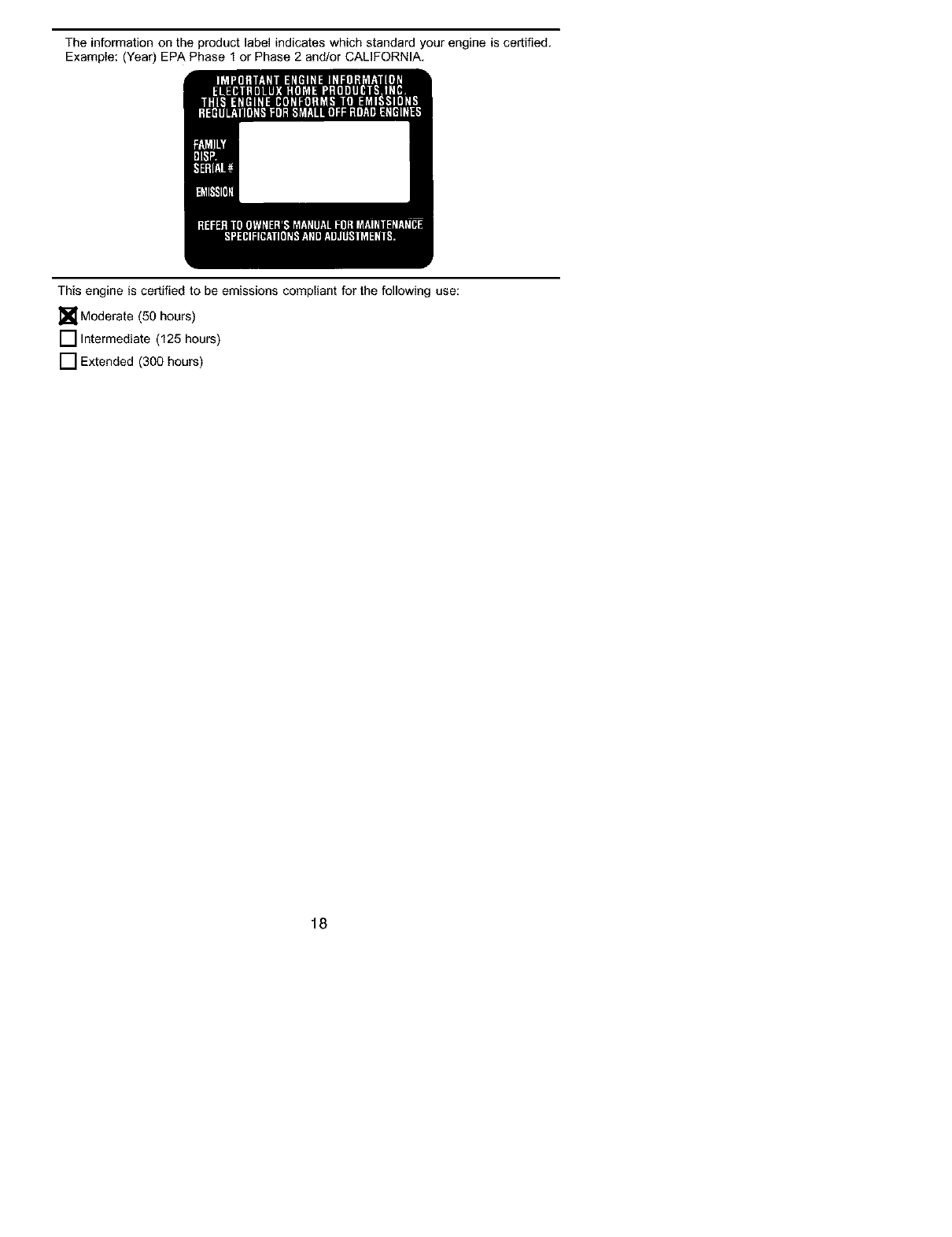
The information on the product label indicates which standard your engine is certified.
Example: (Year) EPA Phase 1 or Phase 2 and/or CALIFORNIA,
This engine is certified to be emissions compliant for the following use:
[] Moderate (50 hours)
[] Intermediate (125 hours)
[] Extended (300 hours)
18
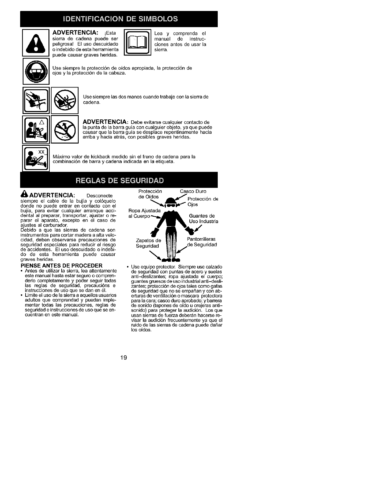
ADVERTENCIA: iEsta _ Lea y comprenda el
sierra de cadena puede ser manual de instruc-
peligrosa! El uso descuidado _ clones antes de usar la
o indebido de esta herramienta sierra.
puede causar graves heridas.
Use siempre la protecci6n de oidos apropiada, la protecci6n de
ojos y la protecci6n de la cabeza.
Use siempre las dos manos cuando trabaje con la sierra de
cadena.
ADVERTENCIA: Debe evitarse cualquier contacto de
[a punta de la barra guia con cualguier objeto, ya que puede
causar que la barra guia se desplace repentinamente hacia
arriba y hacia atr_s, con posibles graves heridas.
Maximo valor de kickback medido sin el freno de cadena para la
combinaci6n de barra y cadena indicada en la etiqueta.
i_ ADVERTENCIA: Desconecte
siempre el cable de la bujia y col6quelo
donde no puede entrar en contacto con el
bujla, para evitar cualquier arranque acci-
dental al preparar, transportar, ajustar o re-
parar el aparato, excepto en el caso de
ajustes al carburador.
Debido a que las sierras de cadena son
instrumentos para cotter madera a alta velo-
cidad, deben observarse precauciones de
seguridad especiales para reducir el riesgo
de accidentes. El uso descuidado o indebi-
do de esta herramienta puede causar
graves heridas.
PIENSE ANTES DE PROCEDER
• Antes de utilizar la sierra, lea attentamente
este manual haste estar seguro o compren-
dedo completamente y poder seguir todas
las reglas de seguridad, precauci6ns e
instrucciones de uso que se dan en 61.
• Limite el uso de la sierra a aquellos usuarios
adultos que comprendad y puedan imple-
mentar todas las precauciones, reglas de
seguridad e instrucciones de uso que se en-
cuentran en este manual.
Protecci6n Casco Duro
de Oidos Protecci6n de
""_l g'W _ Ojos
Ropa Ajustada
al Guantes de
Uso Industria
Zapatos de Pantorrilleras
Seguridad
• Use equipo protector. Siempre use calzado
de seguridad con puntas de acaro y suelas
anti-deslizantes; ropa ajustada el cuer#o;
guantes gruesos de uso industrialanti-desli-
zantes; protecci6n de ojos tales como gafas
de seguridad que no se empaSan y con ab-
erturas de ventillaci6n o mascara protectora
para la cara; casco duro aprobado; y barrera
de sonido (tapones de ofdo u orejeras anti-
sonido) pare proteger la audici6n. Los que
usan sierras de fuerza deber_n hacarse re-
visar la audici6n frecuentemente ya que el
ruido de las sierras de cadena puede daSar
los ofdos.
19
• Mantenga todas las partes del cuerpo aleja-
des de la cadena siempre que el motor est6
en funcionamiento.
• Mantenga a los niSos, espectadores y ani-
males a una distancia minima de 10 metros
(30 pies) del &rea de trabajo o cuando esta
hacienco arrancar el motor.
• No levante ni opera la sierras de cadena
cuando esta feigado, enfermo, ansioso o si
ha tornado alcohol, droges o remedios. Es
imprescindible que ed. est_ en buenas con-
diciones ffsicas y alerta mentelmente. Si ud.
sufre de cualquier condicion que pueda em-
peorar con el trabajo arduo, ases6rese con
su m6dico.
• No ponga en marcha la sierra sin tener un
_rea de trabajo despejada, superficie est-
able para pararse y, si est_ derrubando
_rboles, un camino predeterminado de retro-
ceso.
USE LA SIERRA OBSERVANDO
TODOS LOS PROCEDIMIENTOS
DE SEGURIDAD
• Mantenga las dos manos en las menijas
siempre que el aparato est6 en marcha. El
uso del aparato con una sole meno puede
causer graves heridas al usuario, e los asis-
tentes, o e los espectadores. Les sierras de
cadena est&n diseSadas para que se las use
con las dos manos en todo momento.
• Hage uso de la sierra de cadena t_nicamente
en lugeras exterioras bien ventillados.
• No hega eso de la sierra desde las escaler-
as port,tiles ni de los arboles.
• Asegt_rase de que la cadena no vaya a hac-
er contacto con ningt'Jn objeto antes de pon-
eren marcha el motor. Nunca intente hacer
arrancar la sierra con ]a barra quia en un
corte.
• No aplique presiSn ala sierra al final de los
cortes. Aplicar presi6n puede hacer que
pierde el control al completaPse el corte.
• Pare el motor antes de apoyar la sierra en
ningSn lado.
• No ponga en funcionamiento ]a sierra de ca-
dena si est& daSada, incorrectamente ajes-
tad& o si no est_ armada completa y segu-
ramente. Siempre cambie el protector de
mano immediatamente si _sta quede deSa-
do, roto, o se sale per cualquier motivo.
• Cuando cargue la sierra de cadena en las
manos, h&gelo con el motor parado, el silen-
ciedor elejado del cuerpo, y la cadena hacia
atras y cubierta con un estuche.
MANTENGA LA SIERRA EN BUE*
NAS CONDIClONES DE FUNC*
TIONAMIENTO
• Lleve la sierra de cadena aun distdbuidor
autodzado del servicio para que haga todo
servicio menos aquellos procedimientos Iis-
tados en le secci6n de mantenimiento de
este manual. Por ejempplo, si se usan her-
ramientes que no corresponden pare retirer
o sostener el volante al hacer servicio al em-
brague, pueden ocurdr daSos estructurales
al volante y causar que reviente.
• Aseg6rase de que la cadena se detenga por
completo cuando se suelta el gatillo. Pare
hacer correcciones, vea los AJUSTES AL
CARBURADOR.
• Nunca hega moditicaciones de ninguna in-
dole a su sierra.
• Mentengelas manijassecas, Iimpiesylibras
de aceite o de mezcie de combustible.
• Mantenge les tepas y los tijadores blen fijos.
• Use exclusivamente los accesonos y ra-
puestos Poulan PRO_> recomendados.
MANEJE EL COMBUSTIBLE CON
EXTREMO CUIDADO
• No fume mientres trabeja con el combustible
ni cuando esta haciendo uso de la sierra.
• Elimine todas las posibles fuentes de chis-
paso llamas en las _reas donde se mezcla o
vierte el combustible. No debe haber el fu-
mar, llamas abiertas, o trabajo que podrfa
caesar chispas. Permita qee el motor es frlo
antes de reaprovisioner de combustible.
• Mezcle y vierte el combustible afuera y use
recipiente aprobado para combustibles y
mercado como tel. Limpie todos los der-
rames de combustible.
• Al6jese a por Io mendos 3 metros (10 pies)
del luger de abastecimiento antes de porter
el motor en march&
• Apague el motor y deje qee la sierra se
enfrie en un lugar Iibre de substancias com-
bustibles y no sobre hojes secas, paja, pa-
pel, etc. Retire la tapa lentamente y raabas-
tezca el aparato.
• Guarde el aparato en un espaciuo fresco,
seco y bien ventiledo donde los vapores del
combustible no pueden entrar en contacto
con chispas ni llamas eblertas provenientes
de termotengues, motoras o interruptores
electricos, calefactores centrales, etc.
RECULADA
ADVERTENCIA: Evite reculada le
pueden causar graves heridas. Reeulade
es el movimiento hacia el frante, hacia atr_s
o r_pidamente hecia adelente, esto peede
ocurrir cuando la punta de la barra guia de la
sierra de cadena entre en contacto con cual-
quier objeto como puede ser otra rama o
tronco, o cuando la madera se cierra y atas-
ca mientras se hace el corte. El entrar en
contacto con elgt)n objeto extrafio ala mad-
era le puede causar al usuario la perdida del
control de la sierra de cadena.
• Le Reculada Rotacional puede acontecer
cuando la cadena en movimiento entra en
contacto con algt_nobjeto e? la parte superi-
or de la punta de la barra guJa puede caesar
que le cadene entre al material y se detenga
porun instente. El rasultedoes una reaccion
inversa, a velocidad de rel_mpago, que hace
raculer la barre gufe hacia arriba y hacia
etr_s hacia el usuerio.
• Le Reculada pot Atasco acontecan cuan-
do la madera se cierra y etasca le cadena en
movimiento en el corte a Io largo de la parte
superior de la barra guia yla cadena se de-
tiene repentinamente. Esta detenei6n re-
pentina de la cadena tiene como resultado
una inversi6n de la fuerza de la cadena usa-
da para cortar madera y cause que la sierra
se mueva en sentido opuesto al de la rota-
20
ci6n de la cadena. La sierra directamente
hacia atras an direcci6n al usuario.
• La Reculada pot Impulsibn puede acon-
tatar cuando Is eadena en movimianto entra
en contacto con alg_n objeto extrafio a la
madera en el corte a Io largo de la parte infe-
rior de la barra gula y la cadena se detiene
repentinamente. Esta detencion repentina
de la cadena tira de la sierra adalante y lejos
del usuano y podria hacer facilmente al
usuario perder el control de la sierra.
Para Evitar la Reculada por Atasco:
• Mant_ngase completamente condente de
toda situacion u obstrucci6n que pueda hac-
er que el matedal presione la cadena en la
parte superior o que pueda parar Is cadena
de cualqaier otro modo.
• No corte m_s de un tronco a la vez.
• No retuerza la sierra al retirar la barfs de un
corte ascendiente cuando est& seccionando
troncos.
Para Evitar la Reculada pot Impalsibn:
• Empiece todo corte con el motor acelerado a
fondo y con la caja de la sierra apoyada con-
tra la madera.
• Usa cutlas de pl_stico o de madera (nunca
de metal) para mantener abierto el corte.
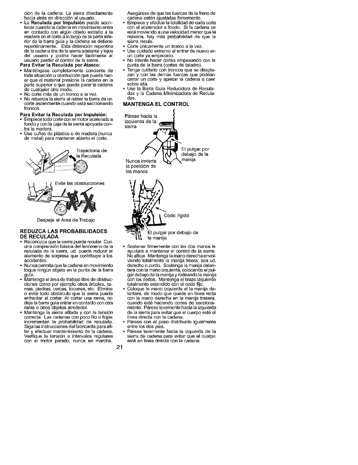
_ Trayectoria de
; la Reculada
nes
Despeje el Area de Trabajo
REDUZCA LAS PROBABILIDADES
DE RECULADA
•Reconozca que la sierra puede recolar. Con
una comprensi6n basica del fenomeno de la
reculada de la sierra, ud. puede reducir el
elemento de sorpresa que contr{buye a los
accidentes.
• Nunca permita que la codena en movimiento
toque ningt]n objeto en la punta de la barra
gu=a.
• Mantenga el _rea de trabajo libre de obstruc-
ciones como por ejemplo otros arboles, ra-
ross, piedras, cereas, tocones, etc. Elimine
o evite todo obst&colo que la sierra pueda
enfrentar al cortar. AI cortar una ram& no
deje la barra guia entrar en contacto con otra
rama o otros objetos alredador.
• Mantenga la sierra afilada y con la tensiSn
correct& Las cadenas con poco filo o nojas
incrementan la probabilidad de reculada.
Siga las instrucciones del fabdcante para aft-
lar y efectuar mantenimiento de la cadena.
Verifique la tensi6n a intervalos regulares
con el motor parado, nunca en march&
AsegQrese de que las tuercas de la freno de
cadena est6n ajustadas firmemente.
• Empiece y efectL'Jela totalidad de cada corte
con el acelerador a fondo. Si la cadena se
est_ moviendo a una velocidad menor que la
m&xima, hay m_s probabilidad de que la
sierra recule.
• Corte _]nicamente un tronco a la vez.
• Use cuidado extremo al entrar de nuevo en
un corte ya empezado.
• No intente hacer cortes empexando con la
punta de la barra (cortes de taladro).
• Tenga cuidado con troncos que se despla-
zan y con las dem&s fuerzas que poddan
cerrar an corte y apretar la cadena o caer
sobre ella.
• Use la Barra Guia Redacidora de Recula-
das y la Cadena Minimizadora de Recula-
das.
MANTENGA EL CONTROL
P&rese hacia la
izquierda de la
sierra
debajo de la
Nunca invierta manija
[a posici6n de
[as manos
odo r{gido
El pulgar por debajo de
la manija
• Sostener firmemente con las dos manos [e
ayudara a mantener el control de la sierra.
No afloje. Mantenga la mano derecha envol-
viendo totalmente la manija trsera, sea ud.
derecho o zurdo. Sostenga la manija delan-
tera con la mano izquierda, colocando el pal-
gar debajo de la manija y rodeando la manija
con los dedos. Mantenga el brazo izquierdo
totalmente extendido con el codo fijo.
• Coloque le mano izquierda el la manija de-
lantera, de modo qae qaede en Ifnea recta
con la mano derecha an la manija trasera,
coando est_ haciendo cortes de secciona-
miento. P_rese levamente hacia la izquierda
de la sierra para evitar que el cuerpo est_ el
linea directa con la cadena.
• P_rese con el peso distribaido igualmente
entre los dos pies.
• P_rese levamente hacia la izquierda de la
sierra de cadena para evitar qua el cuerpo
est_ en linea directa con la cadena.
21
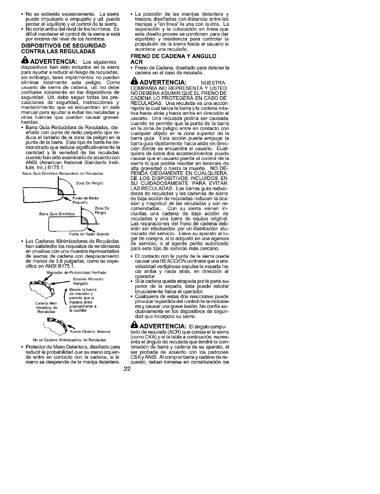
• No se extienda excesivamente. La sierra
puede impulsario o empujado y ud. puede
perder el equilibdo y el control de la sierra.
• No corte aniba del nival de los hombros. Es
dificil mantener el control de la sierra si est_
per encima del nivel de los hombros.
DISPOSITIVOS DE SEGURIDAD
CONTRA LAS REGULADAS
_ADVERTENCIA: Los siguientes
dispositivos han sido incluidos en la sierra
para ayudar a reducir el riesgo de reculadas;
sin embargo, tales implementos no pueden
eliminar totalmente esta peligro. Como
usuario de sierra de cadena, ud. no debe
confiarse solamente en los dispositivos de
seguridad. Ud. debe seguir todas las pre-
cauciones de seguridad, instrucciones y
mantenimiento que se encuentran en este
manual para ayudar a evitar las reculadas y
otras fuerzas que pueden causar graves
heridas.
• Barra Guia Reducidora de Reculadas, dis-
efiada con punta de redio pequeSo que re-
duce el tamafio de la zona de peligro en la
punta de la barra. Este tipo de barra ha de-
monstrado que reduce significativamente la
cantidad y la seriedad de las reculadas
cuando ban sido examinado de acoerdo con
ANSI (American National Standards Insti-
tute, Inc.) B175.1.
Barra GL_iaSim_trica Reducidora de Reculadas
Zona De Peligro
PL_nta de Radio
PequeSo
Z_na De
B_ra Gu[a Sim6trica Peligro
Punta de Radio Grande
• Las Cadenas Minimizadoras de Reculadas
han satisfecho los requisitos de rendimiento
en pruebas con una muestra representativa
de sierras de cadena con desplazamiento
de menos de 3,8 pulgadas, como se espe-
cifica en ANSI B175.1.
Marcador de Profund[dad Perfitado
J Fstab6n Protector
_41 --'''_" Alargado
,tpermite qL_e la
Cadena Mini- _ madera entre
mizadora de gradL_aimente a
Reculadas la cL_chilla
_ Puede Obstruir Material
No un Cadena Minimize, dora de RecLdadas
• Protector de Mano Delantera, diseSado para
reducir la probabilidad que su mano izquier-
da entre en contacto con la cadena, si la
mano se desprende de la manija delantera.
• La posici6n de las manijas delantera y
trasera, diseSadas con distancia entre las
manijas y,"en linea" la una con la otra. La
separacion y la colocaciOn en linea que
este disefio provee se combinan para dar
equilibrio y resistencia para controlar la
propulsion de la sierra hacia el usuado si
acontece una recolada.
FRENO DE CADENA Y ANGULO
ACR
• Freno de Cadena, disefiado para detener la
cadena en el caso de reculada.
ADVERTENCIA: NUESTRA
COMPAi_IA NO REPRESENTA Y USTED
NO DEBERA ASUMIR QUE EL FRENO DE
CADENA LO PROTEGERA EN CASO DE
RECULADAS. Una reculada es una acci6n
rapida la cual lanza la barra y ]a cadena rota-
tiva hacia atr&s y hacia arriba en direcciOn al
usuario. Una reculada podria ser caesada
coando se permite que la punta de la barra
en la zona de peligro entre en contacto con
cualquier objeto en la zona superior de la
barra gura. Esta accion puede empujar la
barra guia r_pidamente hacia atr_s en direc-
ci6n donde se encuentra el usuario. Cual-
quiera de 6stos dos acontecimientos puede
causar que el usuario pierda el control de la
sierra Io que podria resultar en lesiones de
alta gravedad o hasta la muerte. NO DE-
PENDA ClEGAMENTE EN CUALQU]ERA
DE LOS DISPOSITIVOS INCLUIDOS EN
SU CUIDADOSAMENTE PAPA EVITAR
LAS RECULADAS. Las barras guia reduci-
doras de reculadas y las cadenas de sierra
de baja accion de reculadas reducen la oca-
si6n y magnitud de las reculadas y son re-
comendadas. Con su sierra vienen in-
cluidas una cadena de baja acciOn de
reculadas y una barra de equipo original.
Las reparaciones del freno de cadena deb-
er_n ser efectuadas por un distribuidor atu-
roizado del servicio. Lleve su aparato al lu-
gar de compra, si Io adquiri6 en una agencia
de servicio, o al agente perito autorizado
para este tipo de servicio mas cereano.
• El contacto con la punta de la sierra puede
caosar una REACCIC')N contrada qee a ena
velocidad vertiginosa expelsa la espada ha-
cia arriba y hacia atr_s, en direcci6n al
operador.
• Si la cadena queda atrapada por la parte su-
perior de la espada, 6sta peede rebotar
bruscamente hacia el operador.
• Cualquiera de estas dos reacciones puede
provocar la p6rdida del control de la metosie-
rra y causar una grave ]esi6n. No confie ex-
clusivamente en los dispositivos de seguri-
clad que incorpora su sierra.
_, ADVERTENCIA: Elangulocompu-
tado de reculada (ACR) qee consta el la sierra
(come CKA) y el la tabla a continuci6n, repres-
enta el _ngulo de reculada que tendra la com-
binacion de barra y cadena de su aparato, el
ser probada de acoerdo con los padrones
CSA y ANSI. AI comprar barra y cadena de re-
puesto, deben tomarse en consideraci6n los
22
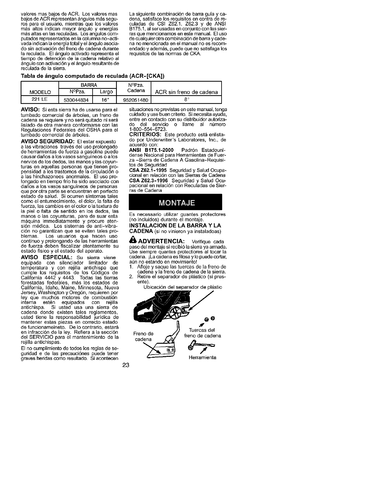
valores mas bajos de ACR. Los valores mas
bajos de ACR representan &ngulos m_s segu-
ros para el usuario, mientras que los valores
m&s altos indican mayor angulo y energfas
m_s altas en las reculadas. Los angulos com-
putados representados en la columna no-acti-
vada indican la energia total y el angulo asocia-
do sin activaciTn del freno de cadena durante
la reculada. El angulo activado representa el
tiempo de detencion de la cadena relativo al
_ngulo con activaciTn y el &ngulo resultante de
reculada de la sierra.
La siguiente combinaci6n de barra guia y ca-
dena, satisface los requisitos en contra de re-
coladas de CSI Z62.1, Z62.3 y de ANSI
B175.1, al ser usadas en conjunto con las sier-
rasque mencionarcos en este manual. El uso
de coalquier otra combinaci6n de barre y cade-
na no mencionada an el manual no es recom-
endado y ademas, puede que no satisfaga los
requisitos de las normas de CKA.
Tabla de bngulo computado de reculada (ACR-[CKA])
BARRA N°Pza,
MODELO N°Pza, Largo Cadena ACR sin freno de cadena
221LE 530044834 16" 952051480 8°
AVISO: Siesta sierra ha de usaree para el
tumbado comercial de &rboles, un freno de
cadena se requiere y no sera quitado ni sera
Iisiado de otra manera conformarse con las
Regulaciones Federales del OSHA para el
tumbado comereial de &rboles.
AVISO SEGURIDAD: El estar expuesto
alas vibraciones traves del uso prolongado
de herramientas de fuerza a gasolina puede
causar daSos a los vasos sanguineos o a los
nervios de los dedos, las manos y las coyun-
turas en aquellas personas que tienen pro-
pensidad a los trastomos de la cireulaci6n o
a las hinchazonees anormales. El uso pro-
Iongado en tiempo frio ha sido asociado con
daSos a los vasos sangufneos de personas
que por otra parte se encuentran en perfecto
estado de salud. Si ocurren sintomas tales
como el entumecimiento, el dolor, la falta de
fuerza, las cambios en el color o la textura de
la piel o falta de sentido en los dedos, los
manos o las coyunturas, pare de suar esta
maquina immediatamente y procure aten-
si6n m6dica. Los sisternas de anti-vibra-
ci6n no garantizan que se eviten tales pro-
blemas. Los usuarios que hacen uso
continuo y prolongando de los herramientas
de fuerza deben fiscalizar atentamente su
estado fisico y el estado del aparato.
AVISO ESPECIAL: Su sierra viene
equipada con silenciador Iimitador de
temperatura y con rejilla antichispa que
cumple los requisitos de los C6digos de
California 4442 y 4443. Todas las tierras
forestadas federales, mQs los estados de
California, Idaho, Maine, Minnesota, Nueva
Jersey, Washington y Oreg6n, requieren por
ley que muchos motores de combusti6n
intema est_n equipados con rejilla
antichispa. Si usted usa una sierra de
cadena donde existen tales reglamentos,
usted tiene la respoosabilidad juridica de
mantener estas piezas en correcto estado
de funcionameineto. De Io contrario, estara
en infraccion de la ley. Refiera a la seccion
del SERVIC]O para el mantenimiento de la
rejilla antichispas.
El no complimiento de todos los reglas de se-
guridad ede las precauciTnes puede tenet
graves heridas como resultado. Si acontecen
situaciones no previstas en este manual, tenga
coidado y use buen criterio. Si necesita ayuda,
entre en contacto con su distdbuidor autodza-
do del servicio o Ilame al nt3mere
1-800-554-6723.
CRITERIOS: Este producto esta enlista*
do por Underwriter's Laboratores, Inc., de
acuerdo con:
ANSI B175.1-2808 Padron Estadouni-
dense Nacional para Herramientas de Fuer-
za -Sierra de Cadena A Gasolina-Requisi-
tos de Seguridad
CSA Z62.1-1995 Seguridad y Salud Ocupa-
cional en relacion con las Sierras de Cadena
CSA Z62.3-1996 Seguridad y Salud Ocu-
pacional en relaciTn con Reculadas de Sier-
ras de Cadena
Es necessario utilizar guantes protectores
(no incluidos) durante el montaje.
INSTALACION DE LA BARRA Y LA
CADENA (si no vinieron ya instaladoas)
_ADVERTENCIA: Verifique cada
paso del montaje si recibi6 la sierra ya armada.
Use siempre quantes protectiores al tocar la
cadena, iLa cadena es filosa y Io puede cortar,
at3n no estando en movimiento!
1. Afloje y saque las tuereas de la freno de
cadena y la freno de cadena de la sierra.
2. Retire el separador de pl_stico (si pres-
ente).
Ubicaci6n del separador de plastic
23
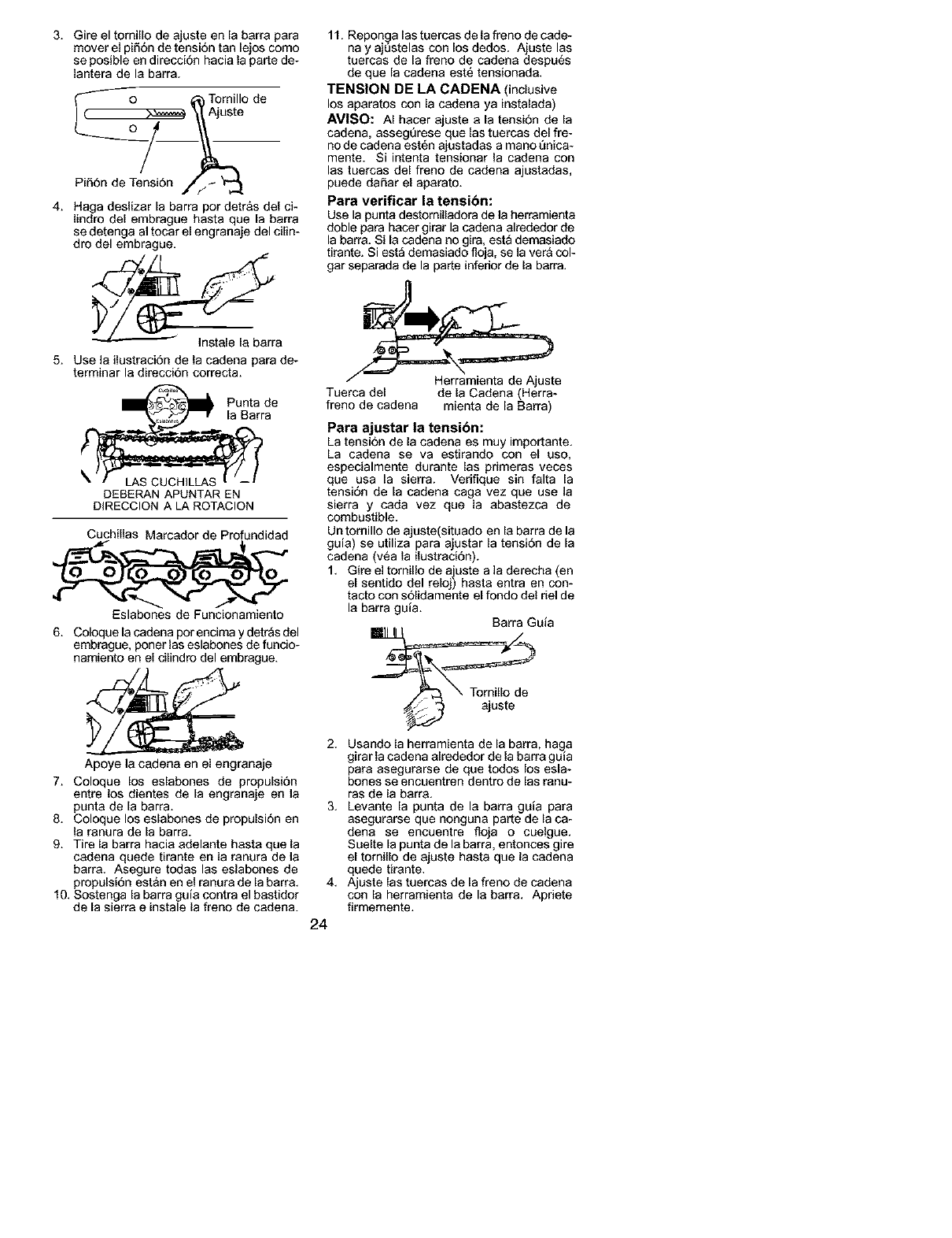
3. Gire el tomillo de ajuste en la barra para
mover el pifi6n de tensi6n tan lejos como
se posible en direcci6n hacia la parte de-
lantera de la barra.
o AjT ni'°de
Pi56n de Tensi6n
4. Haga deslizar la barra par detr&s del ci-
lindro del embrague hasta que la barra
se detenga al tocar el engranaje del cilin-
dro del embrague.
5. Use la ilustraci6n de la cadena para de-
terminar la direeci6n correcta.
_ Punta de
la Barra
DEBERAN APUNTAR EN
DIRECCION A LA ROTACION
Cuchillas Marcador de Profundidad
Eslabones de Funcionamiento
6. Coloque la cadena por encima y detras del
embrague, poner las eslabones de funcio-
namiento en el cilindro del embrague.
Apoye la cadena en el engranaje
7. Coloque los eslabones de propulsi6n
entre los dientes de la engranaje en la
punta de la barra.
8. Coloque los eslabones de propulsi6n en
la ranura de la barra.
9. Tire la barra hacia adelante hasta que la
cadena quede tirante en la ranura de la
barra. Asegure todas las eslabones de
propulsi6n est&n en el ranura de la barra.
10. Sostenga la barra guia contra el bastidor
de la sierra einstale la freno de cadena.
11. Reponga las tuercas de la freno de cade-
nay aj0stelas con los dedos. Ajuste las
tuercas de la freno de cadena despu6s
de que la cadena est6 tensionada.
TENSION DE LA CADENA (inclusive
los aparatos con la cadena ya instalada)
AMISO: AI hacer ajuste a la tensi6n de la
cadena, asseg0rese que las tuercas del fre-
no de cadena est6n ajustadas a mano 0nica-
mente. Si intenta tensionar la cadena con
las tuercas del freno de cadena ajustadas,
puede daSar el aparato.
Para verificar la tensibn:
Use la punta destornilladora de la herramienta
doble para hacer girar la cadena alrededor de
la barra. Si la cadena no gira, est_ demasiado
tirante. Si est_ demasiado floja, se la ver& col-
gar separada de la parte inferior de la barra.
Tuerca del de la Cadena (Herra-
freno de cadena mienta de la Barra)
Para ajustar la tensi6n:
La tensi6n de la cadena es muy importante.
La cadena se va estirando con el uso,
especialmente durante las pdmeras veces
que usa la sierra. Vedfique sin falta la
tensi6n de la cadena caga vez que use la
sierra y cada vez que la abastezca de
combustible.
Un tornillo de ajeste(situado en la barra de la
guia) se utiliza para ajustar la tensi6n de la
cadena (v6a la ilustraci6n).
1. Gire el tomillo de ajuste a ]a derecha (en
el sentido del reloj) hasta entra en con-
tacto con s61idamente el fondo del riel de
la barra guia.
Barra Guia
2. Usando la herramienta de la barra, ha_a
girar la eadena alrededor tie la barra guJa
para asegurarse de que tedos los esla-
bones se encuentren dentro de las ranu-
ras de la barra.
3. kevante la punta de la barra guia para
asegurarse que nonguna parte de la ea-
dena se encuentre floja o cuelgue.
Suelte la punta de la barra, entonces gire
el tomillo de ajuste hasta que la cadena
quede tirante.
4. Ajuste las tuercas de la freno de cadena
con la herramienta de la barra. Apnete
firmemente.
24
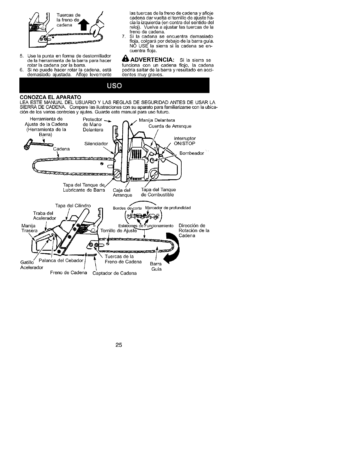
,/_ [_] Tuercas de /[
7ZJ_._) [a freno devil" _
5. Use la punta en forma de destomillador
de la herramienta de la barra para hacer
rotar [a cadeaa por la barra,
6. Si no puede hacer rotar la cadena, esta
demasiado ajustada, Afloje levemente
CONOZCA EL APARATO
las tuercas de la freno de cadena y afloje
cadena dar vuelta el tomillo de ajuste ha-
cia la izquierda (en contra del sentido del
reloj), Vuelva a ajustar las tuercas de la
freno de cadena,
7, Si la cadena se encuentra demasiado
floja, colgar& por debajo de la barra guia,
NO USE la sierra si la cadena se en-
cuentra floja.
41_ADVERTENClA: Si la sierra se
funciona con un cadena flojo, la cadena
podrla saltar de la barra y resultado en acci-
dentes muy graves.
LEA ESTE MANUAL DEL USUARIO Y LAS REGLAS DE SEGURiDAD ANTES DE USAR LA
SIERRA DE CADENA, Compare las ilustraciones con su aparato para familiadzarse con la ubica-
cion de los varios controles y ajutes. Guarde este manual para use futuro.
Herramienta de Protector
Ajuste de la Cadena de Mano
(Herramienta de la Delantera
Barra)
Silenciador
_=_Cadena
/
Tapa del Tanque de/
Lubricante de Barra
Tapa del Cilindro
Traba del
Acelerador
ManUa
Trasera
k
Manija Delantera
Cuerda de Arranque
interruptor
ON'STOP
_._ Bombeador
Gala del Tapa del Tanque
Arranque de Combustible
Bordes de_orte Marcador de profundidad
Eslabones de'Fundonamiento Direccion de
Rotacion de la
Cadena
Tuercas de la
Palanca del Cebador Freno de Cadena
Acelerador
Freno de Cadena Captador de Cadena
Barra
Guia
25
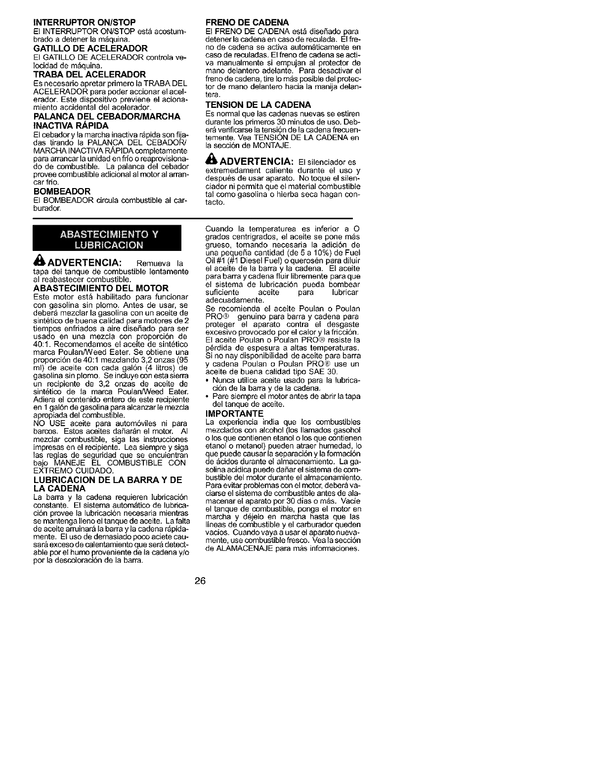
INTERRUPTOR ON/STOP
El INTERRUPTOR ON/STOP esta acostum-
brado a detener la m_quina.
GATILLO DE ACELERADOR
El GATILLO DE ACELERADOR contrela ve-
Iocidad de maquina.
TRABA DEL ACELERADOR
Es necesario apretar primero la TRABA DEL
ACELERADOR pare poder accionar el acel-
erador. Este dispositivo previene el aciona-
miento accidental del acelerador.
PALANCA DEL CEBADOR/MARCHA
INACTIVA RAPIDA
El cebador y la marcha inactiva r_pida son fija-
das tirando la PALANCA DEL CEBADOR/
MARCHA INACTIVA RAPIDA completamente
para arrancar la unidad en frio o reaprovisiona-
do de combustible. La palanca del cebador
provee combustible adicional al motor al arran-
car fdo.
BOMBEADOR
El BOMBEADOR circula combustible al car-
burador.
ADVERTENClA:
FRENO DE CADENA
El FRENO DE CADENA est_ dise_ado pare
detener la cadena en caso de reculada. El fre-
no de cadena se active automaticamente en
caso de reculadas. El freno de cadena se acti-
va manualmente si empujan al protector de
mano delantero adelante. Para desactivar el
freno de cadena, tire Io m_s posible del protec-
tor de mano delantero hacia la manija de]an-
tera.
TENSION DE LA CADENA
Es normal que laa cadenas nueves se estiren
durante los primeres 30 minutos de uso. Deb-
el_ verificaree la tensi6n de la cadena frecuen-
temente. Yea TENSION DE LA CADENA en
la seccion de MONTAJE.
,_ ADVERTENCIA: Elsilenciedores
extremedement celiente durante el uso y
despues de usar aparato. No toque el silen-
ciador ni permita que el material combustible
tal como gasolina o hierba seca hagan con-
tacto.
Remueva le
tapa del tanque de combustible lentamente
al reabastecer combustible,
ABASTECIMIENTO DEL MOTOR
Este motor est_ habilitado para funcionar
con gasoline sin plomo. Antes de usar, se
debera mezclar la gasolina con un aceite de
sintetico de buena calidad para motores de 2
tiempos enfriados a aire diseSado para ser
usado en una mezcla con proporci6n de
40:1. Recomendamos el aceite de sintetico
marca Poulan/Weed Eater. Se obtiene una
proporcion de 40:1 mezclando 3,2 onzas (95
ml) de aceite con cada gal6n (4 litros) de
gasolina sin plomo. Se induye con esta sierra
un recipiente de 3,2 onzas de aceite de
sint6tico de la marca Poulan/Weed Eater.
Adiera el contenido entero de este recipiente
en 1 gal0n de gasolina para alcanzar le mezcla
apropiada del combustible.
NO USE aceite pare autornSviles ni para
barcos. Estos aceites daSaran el motor. AI
mezclar combustible, siga las instrucciones
impresas en el recipiente. Lea siempre y siga
las reglas de seguddad que se encuientran
bajo MANEJE EL COMBUSTIBLE CON
EXTREMO CUIDADO.
LUBRICAClON DE LA BARRA Y DE
LA CADENA
La barra y la cadena requieren lubricaci0n
constante. El sistema autom_tico de lubrica-
cion provee la lubricacion necesaria mientras
se mantenga Ileno el tanque de aceite. La falta
de aceite arruinar& la barra y la cadena r_pida-
mente. El uso de demasiado poco aciete cau-
sar& exceso de calentamiento que ser& detect-
able pot el humo proveniente de la cadena y/o
per la descctoraci6n de la barra.
Cuando la temperaturea es inferior a O
grados centrigrados, el aceite se pone m_s
grueso, tomando necesaria la adici0n de
una pequeSa cantidad (de 5 a 10%) de Fuel
Oil #1 (#1 Diesel Fuel) o querosen para diluir
el aceite de la barra y la cadena. El aceite
pare barra y cadena fluir libremente pare que
el sistema de lubricaci0n pueda bombear
suficiente aceite pare lubricar
adecuadamente.
Se recomienda el aceite Poulan o Poulan
PRO@ genuino pare barra y cadena para
proteger el aparato contra el desgaste
excesivo provocado por el calory la fricci6n.
El aceite Poulan o Poulan PRO® resiste la
p6rdida de espesura a altas temperaturas.
Si no nay disponibilidad de aceite para barra
y cadena Poulan o Poulan PRO® use un
aceite de buena calidad tipo SAE 30.
•Nunca utilice aceite usado para la lubrica-
ci6n de ]a barra y de la cadena.
• Pare siempre el motor antes de abrir la tapa
del tanque de aceite.
IMPORTANTE
La expedencia india que los combustibles
mezciados con alcohol (los Ilamados gasohol
o los que contienen etanol o los que contienen
etanol o metanol) pueden atraer humedad, Io
que puede causar la separacion y la formaci6n
de &cidos durante el almacenamiento. La ga-
soline acidica puede daSar el sistema de com-
bustible del motor durante el almacenamiento.
Para evitar problemas con el motor, deber_ va-
ciarse el sistema de combustible antes de ala-
macenar el aparato pot 30 dlas o mas. Vacie
el tanque de combustible, ponga el motor en
marcha y d6jelo en marcha haste que las
lineas de combustible y el carburador queden
vacios. Cuando vaya a usar el aparato nueva-
mente, use combustible fresco. Vea la seccion
de ALAMACENAJE para m&s informaciones.
26
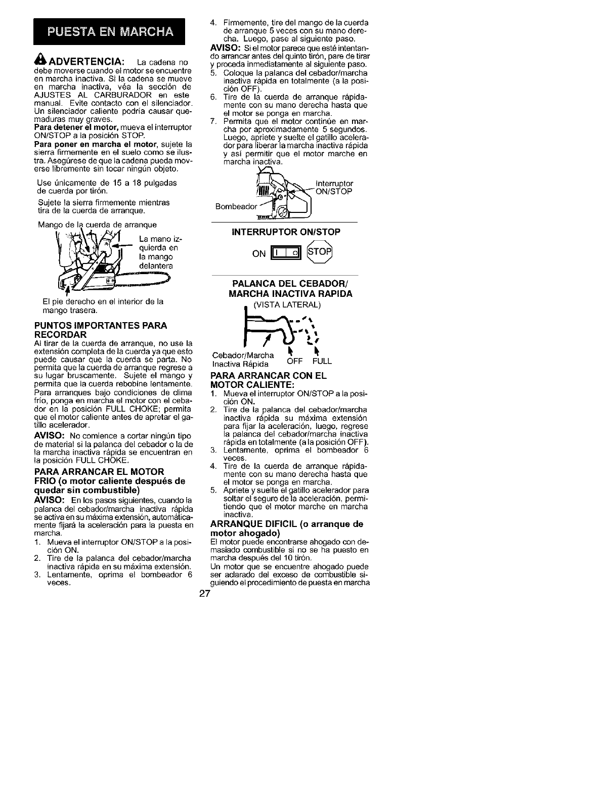
ADVERTENCIA: La cadena no
debe moverse cuando el motor se encuentre
en marcha inactiva. Si la cadena se mueve
en marcha inactiva, v_a la secci6n de
AJUSTES AL CARBURADOR en este
manual. Evite contacto con el silenciador.
Un silenciador caliente podria causar que-
maduras muy graves.
Para detener el motor, mueva el interruptor
ON/STOP a la posici6n STOP.
Para porter en marcha el motor, sujete la
sierra firmemente en el suelo como se ilus-
tra. AsegSrese de que la cadena pueda mow
erse libremente sin tocar ningSn objeto.
Use 6nicamente de 15 a 18 pulgadas
de cuerda por tir6n.
Sujete la sierra firmemente mientras
tira de la cuerda de arranque.
Mango de la cuerda de arranque
• ' '_ La manoiz-
t' _11"4_ "- q uierda en
I t'_,'_/IJ la mango
El pie derecho en el interior de la
mango trasera.
PUNTOS IMPORTANTES PAPA
RECORDAR
AI tirar de la cuerda de arranque, no use la
extensi6n completa de la cuerda ya que esto
puede causar que la cuerda se parta. No
permita que la cuerda de arranque regrese a
su lugar bruscamente. Sujete el mango y
permita que la cuerda rebobine lentamente.
Para arranques bajo condiciones de clima
frio, ponga en marcha el motor con el ceba-
dot en la posicion FULL CHOKE; permita
que el motor caliente antes de apretar el ga-
tillo acelerador.
AVlSO: No comience a cortar ning_n tipo
de material si la palanca del cebador o la de
la marcha inactiva r&pida se encuentran en
la posicion FULL CHOKE.
PAPA ARPANCAR EL MOTOR
FRIO (o motor caliente despu6s de
quedar sin combustible)
AVISO: En los pasos siguientes, cuando la
palanca del cebadodmarcha inactiva r&pida
se activa en su m&xima extension, aL_om&tica-
mente fijar_ la aceleraci6n para la puesta en
marcha.
1. Mueva el interruptor ON/STOP a la posi-
cion ON.
2. Tire de la palanca del cebadodmarcha
inactiva r_pida en su maxima extensi6n.
3. Lentamente, oprima el bombeador 6
veces.
4. Firmemente, tire del mango de la cuerda
de arranque 5 veces con su mano dere-
cha. Luego, pase al siguiente paso.
AVISO: Si el motor parece que est_ intentan-
do arrancar antes del quinto tirSn, pare de tirar
y proceda inmediatamente al siguiente paso.
5. Coloque la palanca del cebador/marcha
inactiva r&pida en totalmente (a la posi-
ciOn OFF).
6. Tire de la cuerda de arranque rapida-
mente con su mano derecha hasta que
el motor se ponga en marcha.
7. Permita que el motor continQe en mar-
cha por aproximadamente 5 segundos.
Luego, apdete y suelte el gatillo acelera-
dot para liberar la marcha inactiva r_pida
y asi permitir que el motor marche en
marcha inactiva.
_lnterruptor
_ON/STOP
Bombeador._
INTERRUPTOR ONISTOP
o. @
PALANCA DEL CEBADOR/
MARCHA INACTIVA RAPIDA
(VISTA LATERAL)
Cebador/Mareha It It
Inactiva R&pida OFF FULL
PAPA ARPANCAR CON EL
MOTOR CALIENTE:
1. Mueva el interruptor ON/STOP a la posi-
ci6n ON.
2. Tire de la palanca del cebador/marcha
inactiva r_pida su m_xima extensi6n
para fijar la aceleracion, luego, regrese
la palanca del cebador/marcha inactiva
rapida en totalmente (a la posici6n OFF}.
3. Lentamente, oprima el bombeador 6
veces.
4. Tire de la cuerda de arranque rapida-
mente con su mano derecha hasta que
el motor se ponga en marcha.
5. Apriete y suelte el gatillo acelerador para
soltar el seguro de la aceleraci6n, permi-
tiendo que el motor marche en marcha
inactiva.
ARPANQUE DIFICIL (o arranque de
motor ahogado)
El motor puede encontrarse ahogado con de-
masiado combustible si no se ha puesto en
marcha despe_s del 10 tir6n.
Un motor que se encuentre ahogado puede
ser adarado del exceso de combustible si-
guiendo el procedimiento de puesta en marcha
27
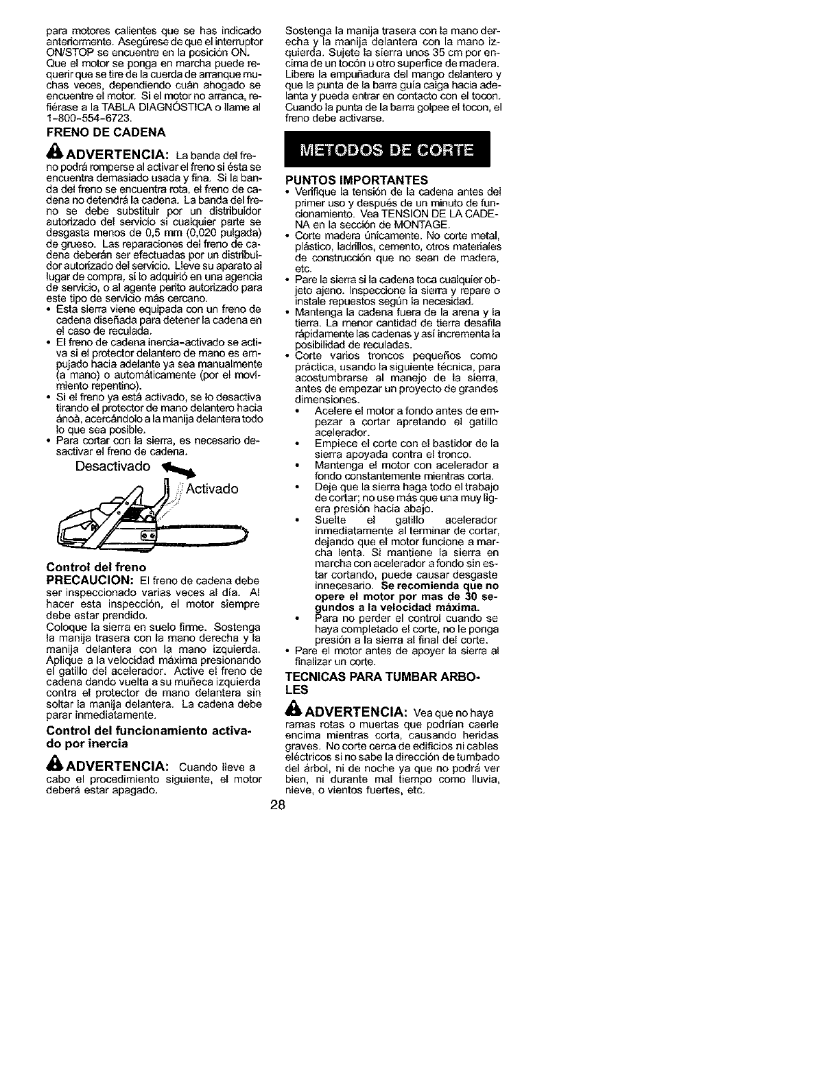
para motores calientes que se has indicado
anteriormente. Aseg6rese de que el interruptor
ON/STOP se encuentre en la posicion ON.
Que el motor se ponga en marcha puede re-
querir que se tire de la cuerda de arranque mu-
chas veces, dependiendo cuan ahogado se
encuentre el motor. Si el motor no arranca, re-
fi6rase a la TABLA DIAGN0STICA o Ilame al
1-800-554-6723.
FRENO DE CADENA
_, ADVERTENCIA: La banda del fie-
no podra romperse al activar el freno si 6sta se
encuentra demasiado usada y fina. Si la ban-
da del freno se encuentra rot& el freno de ca-
dena no detendr_ la cadena. La banda del fie-
no se debe substituir pot un distribuidor
autodzado del servicio si cualqeier parte se
desgasta menos de 0,5 mm (0,020 palgada)
de grueso. Las reparaciones del freno de ca-
dena deberan ser efectuadas pot un distribui-
dot aL_odzado del servicio. Lleve su aparato al
lugar de compra, si Io adquiri6 en una agencia
de servicio, o al agente per]to autorizado para
este tipo de servicio mas cercano.
• Esta sierra viene equipada con un freno de
cadena diseSada para detener la cadena en
el caso de reculada.
• El freno de cadena inercia-activado se acti-
va si el protector delantere de mano es em-
pujado hacia adelante ya sea manualmente
(a mano) o aL_omaticamente (pot el movF
miento repent]no).
• Si el freno ya est_ activado, se Io desactiva
tirando el protector de mano delantero hacia
_no& acerc_ndolo a la manija delantera todo
Io que sea posible.
• Para cortar con la sierra, es necesado de-
sactivar el freno de cadena.
Desactivado
_ , Activado
.¢'
Control del freno
PRECAUCION: El freno de cadena debe
ser inspeccionado varias veces a[ dia. AI
hacer esta inspecci6n, el motor siempre
debe estar prendido.
Coloque [a sierra en sae[o firme. Sostenga
la manija trasera con [a mano derecha y [a
manija delantera con la mano izquierda.
Aplique a la velocidad m_xima presionando
el gatillo del acelerador. Active el freno de
cadena dando vuelta a su mudeca izquierda
contra el protector de mano delantera sin
soltar la manija delantera. La cadena debe
parar inmediatamente.
Control del funcionamiento activa-
do por inercia
_ADVERTENCIA: Cuando Ileve a
cabo el procedimiento siguiente, el motor
deber_ estar apagado.
Sostenga la manija trasera con la mano der-
echa y la manija delantera con la mano iz-
quierda. Sujete la sierra unos 35 cm por en-
cima de un toc6n u otro superfice de madera.
Libere la empudadura del mango delantero y
que la punta de la barra guia caiga hacia ade-
lanta y pueda entrar en contacto con el tocon.
Cuando la punta de la barra golpee el tocon, el
freno debe activarse.
PUNTOSIMPORTANTES
• Verifique [a tensi6n de [a cadena antes del
primer uso y despu6s de un minuto de fun-
cionamiento. Vea TENSION DE LA CADE-
NA en [a secci6n de MONTAGE.
• Corte madera 6nicamente. No corte metal,
pl_sfico, laddllos, cemento, otres mater]ales
de construcci6n que no sean de madera,
etc.
• Pare la sierra si la cadena toca cualquier ob-
jeto ajeno. Inspecdone la sierra y repare o
instale repuestos segt_n la necesidad.
• Mantenga [a cadena fuera de la arena y la
tierra. La menor canfidad de fierra desafila
r_pidamente [as cadenas y asi incrementa la
posibilidad de reculadas.
• Corte varios troncos pequedos como
pr_cfica, usando [a siguiente t6cnica, para
acostumbraree al manejo de la sierra,
antes de empezar un proyecto de grandes
dimensiones.
Acelere el motor a fondo antes de em-
pezar a cortar apretando el gatillo
acelerador.
Empiece e[ corte con el bastidor de [a
sierra apoyada contra el tronco.
Mantenga el motor con acelerador a
rondo constantemente mientras corta.
Deje que la sierra haga todo el trabajo
de cortar; no use masque una muy Jig-
era presi6n hacia abajo.
Suelte eI gati[[o acelerador
inmediatamente al terminar de cortar,
dejando que el motor funcione a mar-
cha lent& Si manfiene la sierra en
marcha con acelerador a rondo sin es-
tar cortando, puede causar desgaste
innecesado. Se recomienda que no
opere el motor por mas de 30 se-
gundos a la velocidad m_xima.
Para no perder el control euando se
haya completado el corte, no [e ponga
presran a [a sierra a[ final de[ corte.
• Pare el motor antes de apoyer la sierra al
finalizar un corte.
TECNICAS PAPA TUMBAR ARBO-
LES
_, ADVERTENCIA: Vea que no haya
ramas rotas o muertas que podrian caede
encima mientras coda, causando heridas
graves. No corte cerca de edificios ni cables
el6ctricos si no sabe la direcci6n de tumbado
del &rbo[, ni de noche ya que no podr_ ver
bien, ni durante ma[ fiempo como Iluvia,
nieve, o vientos fuertes, etc.
28
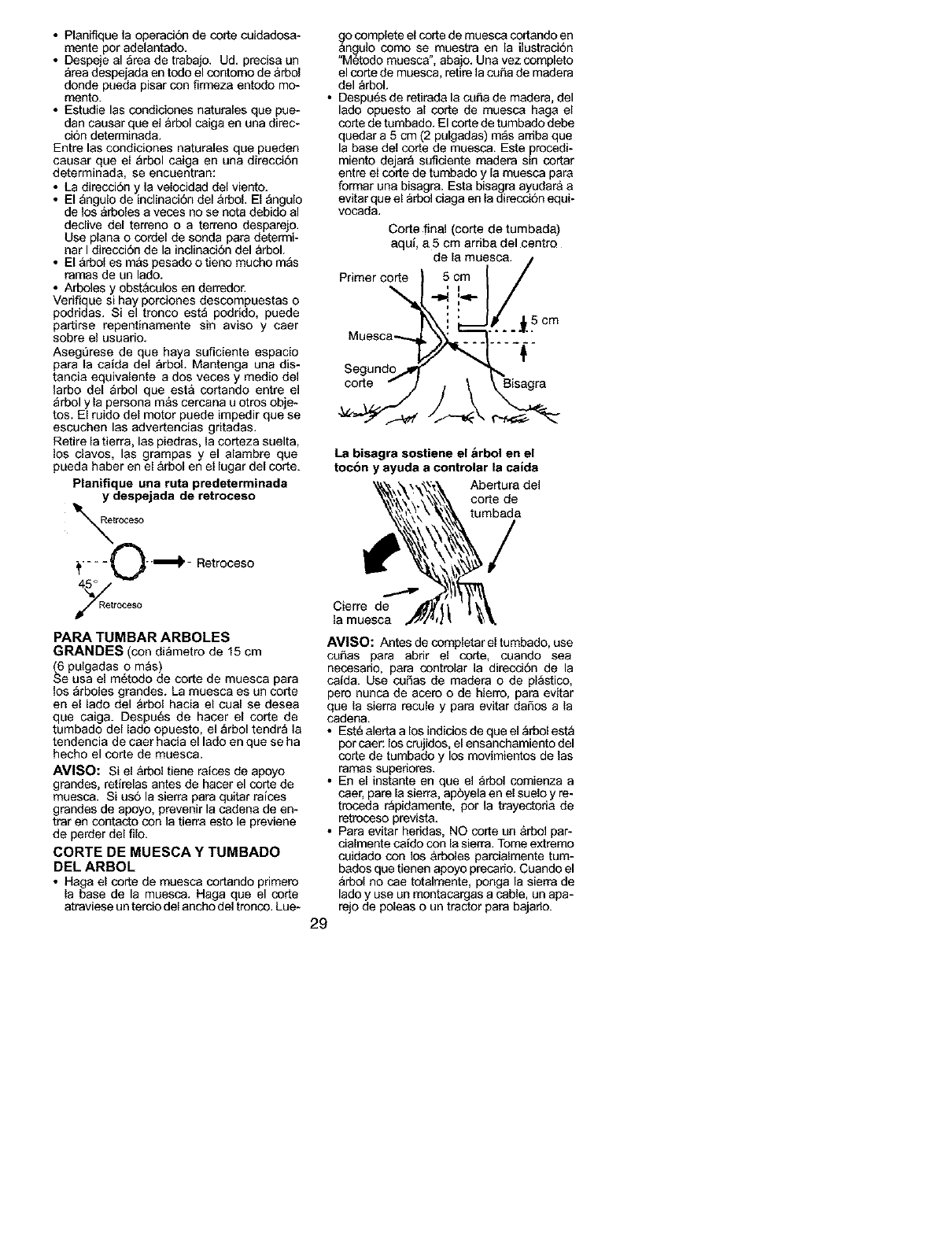
• Planifique la operacion de corte cuidadosa-
mente por adelantado.
• Despeje el area de trabajo. Ud. precise un
_rea despejada en todo el contorno de &rbol
donde pueda pisar con firmeza entodo mo-
mento.
• Estudie las condiciones naturales que pue-
dan causer que el _rbol coiga en una direc-
cion determinada.
Entre las condiciones naturales que pueden
causer que el _rbol caiga en una direcci6n
determinada, se encuentran:
• La direcci6n y ]a velocidad del viento.
• El _ngulo de inclinaci6n del &rboL El angulo
de los arboles a veces no se nota debido al
declive del terreno o a terreno desparejo.
Use plane o cordel de sonda para determi-
nar I direcci6n de la indinaciSn del arbol.
• El &rbol es m&s pesado o tieno mucho m_s
ramas de un lado.
• Arboles y obst&colos en der_dor.
Verifique si hay porciones descompuestas o
podridas. Si el tronco est_ podrido, puede
partirse repentinamente sin aviso y caer
sobre el usuario.
Asegt)rese de que haya suficiente espacio
para la caida del _rboL Mantenga una dis-
tancia equivalente ados veces y medio del
larbo del _rbol que est& cortando entre el
_rbol y la persona m&s cereana u otros obje-
tos. El ruido del motor puede impedir que se
escuchen las advertencias gritadas.
Retire la tierra, las piedras, la corteza suelta,
los clavos, las grampas y el alambre que
pueda haber en el &rbol en el lugar del corte.
Planifique una reta predeterminada
y despejada de retroceso
troceso
;_.... £._"_'- Retroceso
GCeSO
PARA TUMBAR ARBOLES
GRANDES (con all,metro de 15 cm
(6 pulgadas o m_s)
Se usa el m6todo de corte de muesca para
los arboles grandes. La muesca es un corte
en el lado del arbol hacia el cual se desea
que caiga. Despu6s de hacer el corte de
tumbado del lado opuesto, el _rbol tendr_ la
tendencia de caer hacia el lado en que se ha
hecho el corte de muesca.
AVISO: Si el &rbol tiene raices de apoyo
grandes, retirelas antes de hacer el corte de
muesca. Si us6 la sierra para quitar raices
grandes de apoyo, prevenir la cadena de en-
trar en contacto con ]a tierra esto le previene
de perder del filo.
CORTE DE MUESCA Y TUMBADO
DEL ARBOL
• Haga el corte de muesca cortando primere
la base de la muesca. Haga que el corte
atraviese un tercio del ancho del tronco. Lue-
a_ocomplete el corte de muesco cortando en
,, n_ulo como se,,muestra, en la ilustracion
Metodo muesca, aba]o. Una vez complete
el corte de muesca, retire la cu_a de madera
del _rbol.
• Despu6s de retirada la cufta de madera, del
lado opuesto al corte de muesco haga el
corte de tumbado. El corte de tumbado debe
quedar a 5 cm (2 pulgadas) m_s arriba que
la base del corte de muesca. Este precedi-
miento dejar_ suficiente madera sin cortar
entre el corte de tumbado y la muesca pare
formar una bisagra. Esta bisagra ayudar& a
evitar que el _rbol ciaga en la direccion equi-
vocada.
Corte final (corte de tumbada)
aqui, a 5 cm ardba del centro
de la muesca. /
Primer corte 5 cm /
",-,4,":÷/
Uuesca--.... ......
Segund%,,I
co.e--/
La bisagra sostiene el brbol en el
tocbn y ayuda a controlar la caida
Abertura del
corte de
tumbada
Cierre de
la muesca
AVISO: Antes de completar el tumbado, use
cuftas pare abrir el corte, cuando sea
necesario, pare contrelar la direcci6n de la
caida. Use cuSas de madera o de pl_stico,
pere nunca de acere o de hierro, para evitar
que la sierra recule y para e'vitar daSos a la
cadena.
• Est6 alerta a los indicios de que el _rbol est_
por caer: los crujidos, el ensanchamiento del
corte de tumbado y los movimientos de las
ramas superiores.
• En el instante en que el _rbol comienza a
caer, pare la sierra, apbyela en el suelo y re-
treceda r_pidamente, por la trayectoda de
retreceso prevista.
• Para evitar heddas, NO corte un &rbol par-
cialmente caido con la sierra. Tome extremo
coidado con los &rboles parcialmente tum-
bados que tienen apoyo precario. Cuando el
&rbol no cae totalmente, ponga la sierra de
lado y use un montacargas a cable, un apa-
rejo de poleas o un tractor para bajado.
29
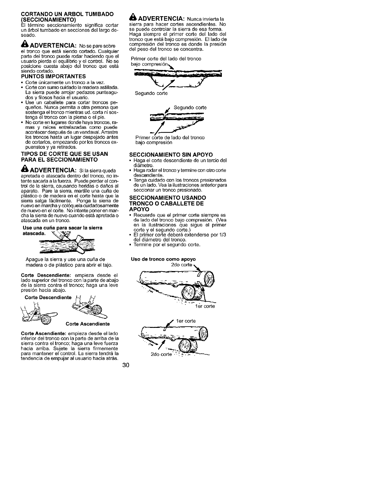
CORTANDO UN ARBOL TUMBADO
(SECCIONAM|ENTO)
El t_rmino secoionamiento significa cortar
un _rbol tumbado en secciones del largo de-
seado.
_ADVERTENCIA: No se pare sobre
el trenco que est_ siendo cortado. Caaiquier
parte del tronco puede redar haciendo que el
usuario pierda e[ equi[ibrio y el control. No se
posicione caesta abajo del tronco que esta
siendo cortado.
PUNTOS IMPORTANTES
•Corte 5nicamente un trenco a la vez.
• Corte con sumo coidado la madera astigada.
La sierra paede arrojar pedazos punteagu-
dos y filosos hacia el usuario.
• Use un cabal[ete para cortar trencos pe-
queSos. Nunca permita a otra persona que
sostenga el trenco mientras ud. corta ni sos-
tenga el tronco con la piema o el pie.
• No corte en lugares donde haya troncos, ra-
mas y farces entrelazadas como puede
acontecer despu6s de un vendaval. Arrastre
los troncos hasta un lugar despejado antes
de cortarlos, empezando per los troncos ex-
puenstos y ya retirados.
TIPOS DE CORTE QUE SE USAN
PARA EL SECClONAMIENTO
_ADVERTENCIA: Si la sierra queda
apretada o atascada dentro del trenco, no in-
tente sacarla a [a fuerza. Puede perder e[ con-
tro[ de la sierra, causando heridas o daSos a[
aparato. Pare la sierra, martiHe una coSa de
plastico o de madera en el corte hasta que la
sierra salga facilmente. Ponga la sierra de
nuevo en mareha y coloquela cuidadosamente
de nuevo en el corte. No intente poner en mar-
cha la sierra de nuevo cuando est_ apretada o
atascada en un trenco.
Use una calm para sacar la sierra
atasca_
Apague la sierra y use una curia de
madera o de p[astico para abrir el tajo.
Corte Descendiente: empieza desde el
lado superior del tronco con la parte de abajo
de la sierra contra el tronco; haga una leve
presiSn hacia abajo.
Corte Descendiente _J
_C_e
Corte Ascendiente: empieza desde el lado
inferior del tronco con la parte de arriba de la
sierra contra el tronco; haga una leve fuerza
hacia arriba. Sujete la sierra firmemente
para mantener el control. La sierra tendr_ la
tendencia de empujar al usuario hacia atr_s.
A
411ADVERTENCIA: Nunca invierta la
sierra para haeer cortes ascendientes. No
se puede controlar la sierra de esa forma.
Haga siempre el primer corte del lado del
tronco que est_ bajo compresi6n. El lado de
compresi6n de[ tronco es donde [a presi6n
del peso del tronco se concentra.
Primer corte del laclo del tronco
bajo compresi6n,_.
Segundo corte
_, Segundo corte
Primer corte de lado del tronco
baio compresion
SECCIONAMIENTO SIN APOYO
•Haga e[ corte descendiente de un tercio del
di_metre,
• Haga redar el trenco y termine con otro corte
descendiente.
• Tenga cuidado con los troncos presionados
de un lado. Vea la ilustraciones anterior para
seccionar un trenco presionado.
SECClONAMIENTO USANDO
TRONCO O CABALLETE DE
APOYO
•Recaerde que el primer corte siempre es
de lado del tronco bajo compresiSn. (Vea
en la ilustraciones que sigue el primer
corte y el segundo corte.)
• El primer corte debera extenderse por 1/3
del di&metro del tronco.
• Termine por el segundo corte.
Uso de tronco como apoyo
I er corte
1er corte
30
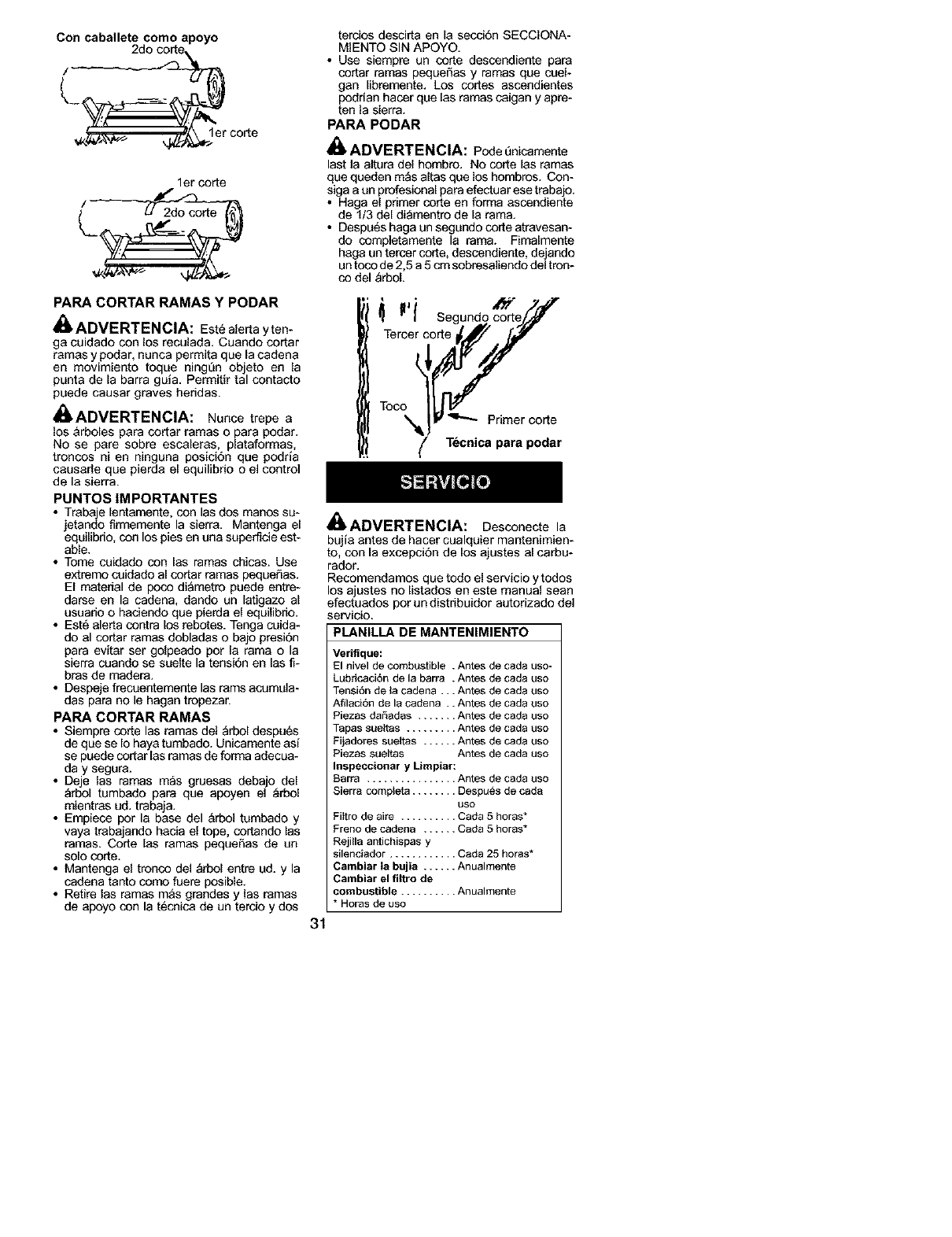
Con caballete como apoyo
2do corte
lerco{te
1er corte
PARA CORTAR RAMAS Y PODAR
ADVERTENCIA: Este alerta y ten-
ga euidado con los reculada. Cuando cortar
ramas y podar, nunca permita que la cadena
en movimiento toque ningL_n objeto en la
punts de la barfs guia. Permitir tal contacto
puede causar graves heridas.
_,ADVERTENClA: Nunce trepe a
los &rboles para cortar ramas o para podar.
No se pare sobre escaleras, plataformas,
troncos ni en ninguna posici6n que poqda
causarle que pierda el equilibrio o el control
de la sierra.
PUNTOS IMPORTANTES
• Trabaje lentamente, con las dos manos su-
jetando firmemente la sierra. Mantenga el
equilibrio, con los pies en una superficie est-
able.
• Tome cuidado con Ins ramas chicas. Use
extremo coidado al cortar ramas pequeSas.
El matedal de poco diametro puede entre-
darse en la cadena, dando un latigazo al
usuario o haciendo que pierda el equilibrio.
• Est6 ale{ta contra los rebotes. Tenga cuida-
do al co{tar ramas dobladas o bajo presiOn
para evitar ser golpeado per la rama o la
sierra cuando se suelte la tensibn en las fi-
bras de readers.
• Despeje frecuentemente las rams acumula-
das parr no le hagan tropezar.
PARA CORTAR RAMAS
• Siempre corte las ramas del _rbol despu_s
de que se Io haya tumbado. Unicamente asi
se puede cortar las ramas de forms adecua-
day segura.
• Deje las ramas m_s gruesas debajo del
_rbol tumbado parr que apoyen el _rbol
mientras ud. trabaja,
• Empiece por la base del &rbol tumbado y
vaya trabajando hacia el tope, cortando las
ramas. Corte las ramas pequeF_as de un
solo cod:e.
• Mantenga el tronco de] _rbol entre ud. y la
cadena tanto corco fuere posible.
• Retire las ramas m_s grandes y las ramas
de apoyo con la t6cnica de un tereio y dos
tercios desci{ta en la secci6n SECCIONA-
MIENTO SIN APOYO.
• Use siempre un corte descendiente parr
cortar ramas peque5as y ramas que coel-
gan libremente. Los cortes ascendientes
podrian hacer que Ins ramas caigan y apre-
ten la sierra.
PARA PODAR
_ADVERTENCIA: Poqe _nicamente
last la altura del hombre. No corte Ins ramas
que queden m_s altas que los hombres. Con-
sigaa ue profesional para efectuar ese trabajo.
•Haga el primer corte en forma ascendiente
de I/3 del diamentro de la rama.
• Despu6s haga un segundo corte atravesan-
do completamente la rama. Fimalmer_e
hags un tercer cot[e, descendiente, dejando
un toco de 2,5 a 5 cm sobresaltendo del tree-
co del _rboL
{ll Segundo co_//
Tercer eo_!
Tooo _ _-"_ Primer corte
T_cnica para podar
ADVERTENCIA:
31
Desconecte la
bujia antes de hacer cualquier mantenimien-
to, con la excepci6n de los ajustes al carba-
rador.
Recomendamos que todo el servicio y toqos
los ajustes no listados en este manual seat]
efectuados por un distribuidor autorizado de]
servic{o.
PLANILLA DE MANTENIMIENTO
Veriflque:
El nivel de combustible .Antes de cads uso-
LubticaciSn de la barfs . Antes de cads uso
Tensi6n de la cadens... Antes de cads uso
AfilaciSn de la cadena .. Antes de cads uso
Piezas dar_adas ....... Antes de cads uso
Tapas sue_tas ......... Antes de cads uso
Fijadores sue{tas ...... Antes de cads uso
Piezas sueltas Antes de cads uso
Inspeccionar y Limpiar:
Barra ................ Antes de cads _s_
Sierra compteta ........ Despues de cads
uso
Fittro de sire .......... Carla 5 horns*
Freno de cadena ...... Cada 5 horas*
Rejilla antichispas
silenciador ............ Cada 25 horns*
Cambiar la bujia ...... Anualmente
Cambiar el flltro de
combustible .......... Anualmente
*HOrBS de Ue.x3
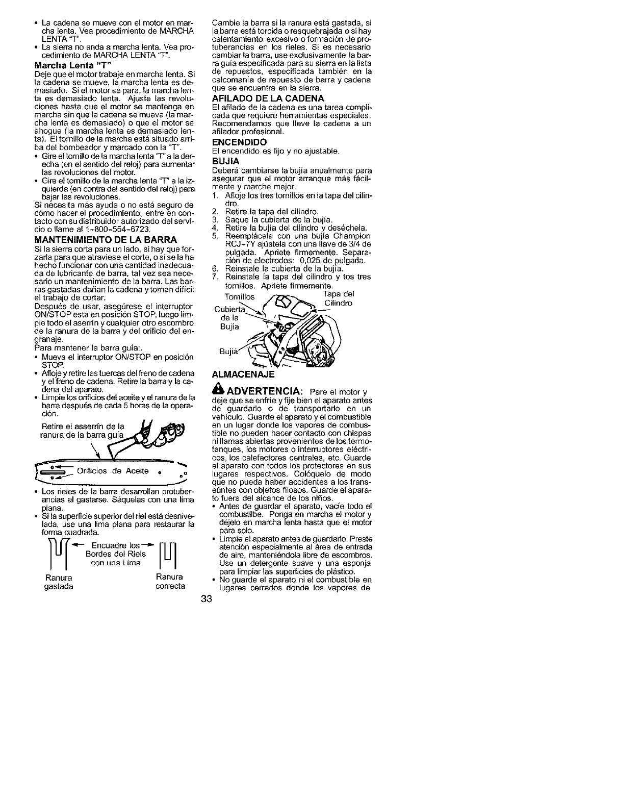
• La cadena se mueve con el motor en mar-
cha lent& Vea procedimiento de MARCHA
LENTA "T".
• La sierra no anda a marcha lent& Vea pro-
cedimiento de MARCHA LENTA "T'.
Marcha Lenta "T"
Deje que el motor trabaje en marcha lent& Si
la cadena se mueve, la mareha lenta es de-
masiado. Si el motor se para, la mareha len-
ta es demasiado lent& Ajuste las revolu-
ciones hasta que el motor se mantenga en
marcha sin que la cadena se mueva (la mar-
cha lenta es demasiado) o que el motor se
ahogue (la mareha lenta es demasiado len-
ta). El tomillo de la marcha est_ situado arri-
ba del bombeador y marcado con la "T".
• Gire el tomillo de la marcha lenta 'q-"a la der-
echa (en el sentido del reloj) para aamentar
las revoluciones del motor.
• Gire el tomillo de la marcha lenta 'q-" a la iz-
quierda (en contra del sentido del reloj) para
bajar las revoluciones.
Si necesita mas ayuda o no esta seguro de
como hacer el procedimiento, entre en con-
tacto con su distribuidor autorizado del servi-
cio o Ilame al 1-800-554-6723.
MANTENIMIENTO DE LA BARRA
Si la sierra corta para un lado, si hay que for-
zarla para que atraviese el corte, o si se la ha
hecho funcionar con una cantidad inadecea-
da de lubricante de barra, tal vez sea nece-
sario un mantenimiento de la barra. Las bar-
ras gastadas daSan la cadena ytoman dificil
el trabajo de cortar.
Despu6s de usar, asegQrese el interreptor
ON/STOP est& en posicion STOP, luego lim-
pie todo el aserrin y cualquier otto escombro
de la ranura de la barra y del orificio del en-
granaje.
Para mantener la barra guia:.
• Mueva el interruptor ON/STOP en posicion
STOP.
• Afloje y retire las tuercas del freno de cadena
y el freno de cadena. Retire la barre y la ca-
dena de[ aparato.
• Umpie los odficios del aceite y el ranura de la
barra despu6s de coda 5 horas de la opera-
ci6n.
Retire el aaaerrin de la _f
Orificios de Aceite • oQ
• Los rielea de la barra deaarrollan pretuber-
ancias a] gastarse. S&qaelas con ana lima
plana.
• Si la supefficie superior del riel est_ desnive-
lad& use una lima plana para restaurar la
forma cuadrada.
-- Encuadre los --_" [U]
Bordes del Riels
con una Lima
Ranura Ranura
gastada correcta
Cambie la barra si la ranura est_ gastada, si
la barra est_ torcida o resquebrajada o si hay
calentamiento excesivo o formaci6n de pro-
tuberanoias en los rieles. Si es necesario
cambiar la barra, use exclusivamente la bar-
ra guia especificada para su sierra en la lista
de repuestos, especificada tambi6n en la
calcomania de repuesto de barra y cadena
que se encuentra en la sierra.
AFILADO DE LA CADENA
El afilado de la cadena es una tarea compli-
cada que requiere herramientas especiales.
Recomendamos que Ileve la cadena a un
afllador profesionaL
ENCEND|DO
El eneendido es fijo y no ajastable.
BUJIA
Debera eambiarse [a bujia anaa{mente para
asegurar que el motor arranque m_s f_cil-
mente y marche mejor.
1. Afloje los tres tornillos en la tapa del cilin-
dro.
2. Retire la tapa del ci[indro.
3. Saque la cubierta de la bujla.
4. Retire la bajla del cilindro y des6chela.
5. Reempl_cela con una bujia Champion
RCJ-7Y aj5stela con una leave de 3/4 de
pulgada. Apriete firmemente. Separa-
ci6n de electrodos: 0,025 de pulgada.
6. Reinsta{e [a cubierta de la bujia.
7. Reinstale [a tapa del cilindro y tos tres
tomillos. Apriete firmemente.
Tornillos Cilindro
de la
Bujia
ALMACENAJE
_ADVERTENCIA: Pareel motory
deje que se enfrie y fije bien el aparato antes
de guardarlo o de transportarlo en un
veh{culo. Guarde el aparato y el combustible
en un lugar donde los vapores de combus-
tible no pueden hacer contacto con chispas
ni llamas abiertas provenientes de los termo-
tanques, los motores o interruptores electri-
cos, los calefactores centrales, etc. Guarde
el aparato con todos los protectores en sus
lugares respectivos. Col6quelo de modo
que no pueda haber acoidentes a los trans-
e5ntes con objetos filosos. Guarde el apara-
to fuera del alcanoe de los ni5os.
• Antes de guardar el aparato, vac{e todo el
combustilbe. Pnoga en marcha el motor y
d6jelo en marcha lenta hasta que el motor
para solo.
• Limpie el aparato antes de guardado. Preste
atenci6n especialmente al _rea de entrada
de aire, manteniendola libre de escombres.
Use un detergente suave y una esponja
para limpiar las superficies de pl_stico.
• No guarde el aparato ni el combustible en
lugares cerrados donde los vapores de
33
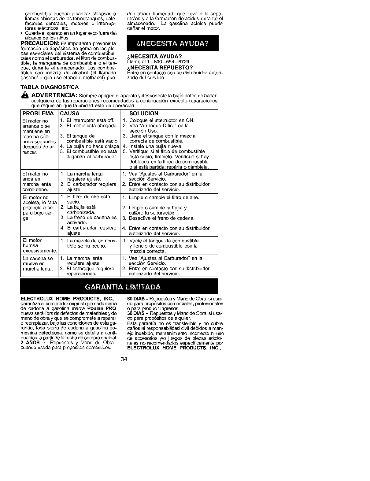
combustiblepuedanalcanzarchispsaso
llamasabiertasdelostermotanques,cale-
factorescentrales,motoreso interrup-
toresel_ctricos,etc.
• Guarde el aparato en un lugar seco fuera del
alcance de los ni_os.
PRECAUCION: Es importante prevenir la
formacon de dep6sitos de goma en las pie-
zes esenciales del sistema de combustible,
tales como el carburador, el filtro de combus-
tible, la manguera de combustible o el tan-
que, durante el aimacenado. Los combus-
tibles con mezcla de alcohol (el Ilamado
gasohol o que use etanol o methanol) pue-
den atraer humeded, que Ileva e le sepa-
rac'on y ala formec'on de'acidos durante el
almecenado. La gasoline acidica puede
da_ar el motor.
&NECESITA AYUDA?
Llame al 1-800-554-6723.
_NECESITA REPUESTO?
ntre en contecto con su distribuidor autori-
zado del servicio.
TABLA DIAGNOSTICA
_, ADVERTENCIA: Siempre apague el aparato ydesconecte le bujie antes de hacer
cualquiera de las reparaciones recomendadas a continuaci6n excepto reparaciones
que requieran que la unidad est_ en operaci6n.
PROBLEMA
El motor no
arranca o se
mantiene en
marcha s61o
unos segundos
despu6s de ar-
ranca_
El motor no
anda en
marcha lente
como debe.
CAUSA
1. El interruptor est& off.
2. El motor esta ahogado.
3. El tanque de
combustible esta vacio.
4. La bujia no hace chispa.
5. El combustible no est_
Ilegando al carburador.
SOLUCION
1. Coloque el interruptor en ON.
2. Vee "Arranque Dificir' en la
seccion Uso.
3. Llene el tanque con la mezcla
correcte de combustible.
4. Instele una bujia nueve.
5. Verifique si el filtro de combustible
est_ sucio; Ifmpielo. Verifique si hay
dobleces en la llnea de combustible
o siesta partida: rep_rla o c_mbiela.
1. Vea "Ajustes al Carburador" en la
secci6n Servicio.
2. Entre en contacto con su distribuidor
autorizado del servicio.
1. La mercha lenta
requiere ajuste.
2. El cerburador requiere
ajuste.
1. El filtro de eire est&
sucio.
2. La bujfa esta
carbonizada.
3. La freno de cadena es
activado.
4. El cerburador requiere
ajuste.
1. La mezcle de combus-
tible se ha hecho.
El motor no 1. Limpie o cambie el filtro de aire.
acelere, le falta
potencia o se 2. Limpie o cambie la bujfa y
para bajo car- calibre la separaci6n.
ga. 3. Desactive el freno de cadene.
4. Entre en contacto con su distribuidor
autorizado del servicio.
El motor 1. Vacie el tanque de combustible
humee y Ilbnelo de combustible con la
excesivamente mezcla correct&
La cedena se 1. La marcha lente 1. Vea "Ajustes al Carburador" en la
mueve en requiere ajuste, secci6n Servicio.
marcha lenta. 2. El embrague requiere 2. Entre en contacto con su distribuidor
reparaciones, autorizado del servicio.
ELECTROLUX HOME PRODUCTS, INC.,
garantiza al comprador original que cada sierra
de cadena agaselina marca Poulan PRO
nueva sera Iibre de defectos de meteriales y de
mano de obra y que se compromete a reparar
o reemplazer, bajo las condidones de esta ga-
rantia, toda sierra de cadena a gasolina do-
mestica defectuosa, como se detalla a conti-
nua_6n, e pertir de la fecha de compra original:
2 ANOS -Repuestos y Mano de Obra,
cuando usada para prop6sitos dom_sticos.
60 DIAS - Repuestos y Meno de Obra, si usa-
do pare prop6sitos comerciales, profesionales
opara producir ingresos.
30 DIAS - Repuestos y Mano de Obra, si usa-
do para prop6sitos de alquiler.
Esta garentfa no es transferible y no cubre
defios ni responsabilidad civil debidos e man-
ejo indebido, mantenimiento incorrecto ni uso
de accesorios y/o uegos de piezes adicio-
hales no recomendados especfficamente per
ELECTROLUX HOME PRODUCTS, INC.,
34
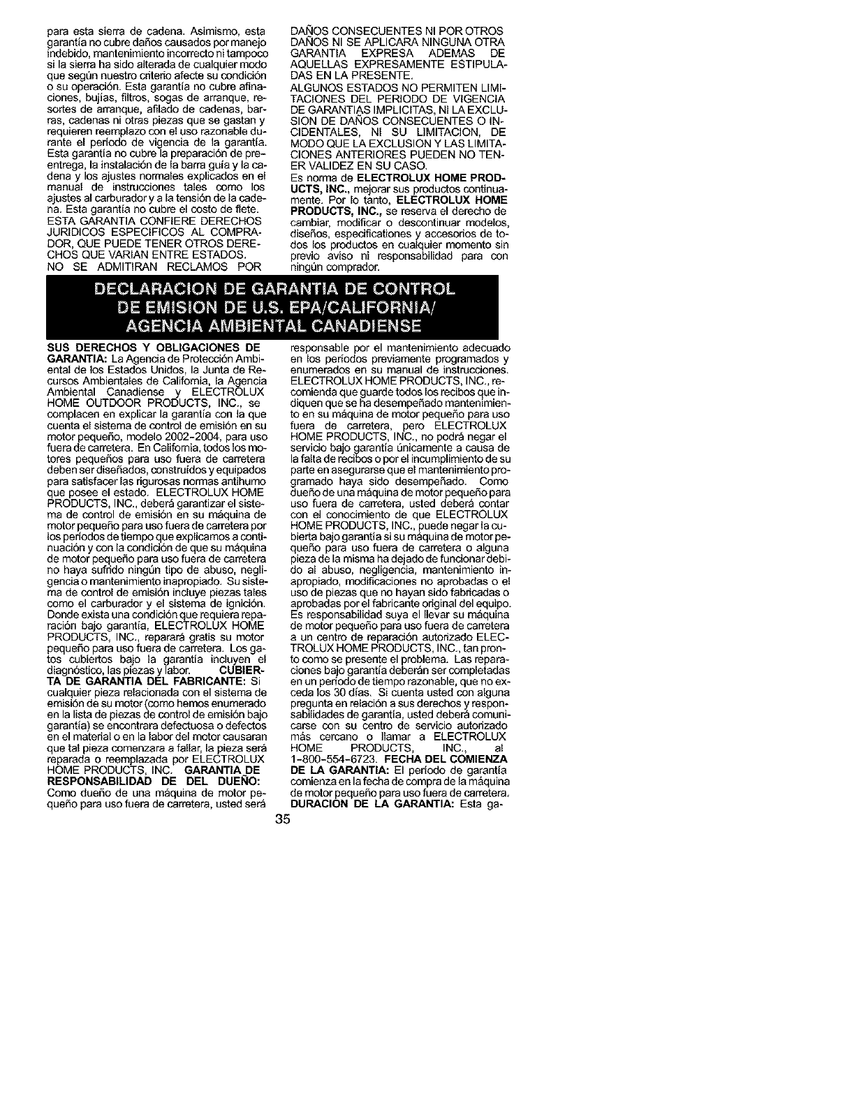
para esta sierra de cadena. Asimismo, esta
garantia no cubre daSos causados par manejo
indebido, mantenimiento incorrecto ni tampoco
si la sierra ha sido alterada de cualquier modo
que segSn nuestro critedo afecte su condid6n
o su operaci6n. Esta garantia no cubre aSna-
clones, bujias, filtros, sagas de arranque, re-
sortes de arranque, afilado de cadenas, bar*
ras, cadenas ni otras piezas que se gastan y
requieren reemplazo con el uso razonable du-
rante el periodo de vigencia de la garantfa.
Esta garantia no cubre la preparaci6n de pre-
entrega, la instalaci6n de la barra gala y la ca-
dena y los ajustes normales explicados en el
manual de instrucciones tales como los
ajustes al carburador y a la tensi6n de la cade-
ha. Esta garantfa no cubre el costo de flete.
ESTA GARANTIA CONFIERE DERECHOS
JURIDICOS ESPEClFICOS AL COMPRA-
DOR, QUE PUEDE TENER OTROS DERE-
CHOS QUE VARIAN ENTRE ESTADOS.
NO SE ADMITIRAN RECLAMOS POR
DAklOS CONSECUENTES NI POR OTROS
DAklOS NI SE APLICARA NINGUNA OTRA
GARANTIA EXPRESA ADEMAS DE
AQUELLAS EXPRESAMENTE ESTIPULA-
DAS EN LA PRESENTE.
ALGUNOS ESTADOS NO PERMITEN LIMI-
TAClONES DEL PERIODO DE VlGENClA
DE GAP.ANTIAS IMPUCITAS, NI LA EXCLU-
SION DE DANOS CONSECUENTES O IN-
CIDENTALES, NI SU LIMITACION, DE
MODO QUE LA EXCLUSION Y LAS LIMITA-
CLONES ANTERIORES PUEDEN NO TEN-
ER VALIDEZ EN SU CASO.
ES norma de ELECTROLUX HOME PROD-
UCTS, INC., mejorar sos productos continua-
mente. Pot Io tanto, ELECTROLUX HOME
PRODUCTS, INC., se reserva el derecho de
cambiar, modificar o descontinuar modelos,
disefios, especificationes y accasorios de to-
dos los productos en cualquier momento sin
previo aviso ni responsabilidad para con
ningQn comprador.
SUS DERECHOS Y OBLIGACIONES DE
GARANTIA: La Agenda de Proteoci6n Ambi-
ental de los Estados Unidos, la Junta de Re-
oursos Ambientalas de California, la Agencia
Ambiental Canadiense y ELECTROLUX
HOME OUTDOOR PRODUCTS, INC., se
complacan en explicar la garantia con la que
cuenta el sistema de control de emision en su
motor pequefio, modelo 2002-2004, para oso
fuera de carretera. En California, todos los mo-
totes pequefios para uso fuera de carretera
deben ser diseSados, construidos y equipados
para satisfacer las dgurosas normas antihumo
que posee el estado. ELECTROLUX HOME
PRODUCTS, INC., debera garantizar el siste-
ma de control de emisi6n an sa maquina de
motor pequeSo para oso fuera de carretera por
los periodos de tiempo que explicamos a conti-
nuacion y con la condicion de que su m&quina
de motor paque£Lopara uso fuera de carretera
no haya sufrido ningl3n tipo de abuso, negli-
gencia o mantenimiento inapropiado. Su siste-
ma de control de emisi6n incluye piezas tales
como el carburador y el sistema de ignici6n.
Donde axista una condicion que requiera repa-
raci6n bajo garantia, ELECTROLUX HOME
PRODUCTS, INC., reparar_ gratis su motor
pequeSo para oso fuera de carretera. Los ga-
tos cubiertos bajo la garantia inclayen el
diagn&stico, las piezas y labor. CUBIER-
TA DE GARANTIA DEL FABRICANTE: Si
cualquier pieza relacionada con el sistema de
emisi6n de su motor (como hemos enumerado
en la lista de piezas de control de emisi6n bajo
garantia) sa encontrara defectuosa o defectos
an el material o en la labor del motor causaran
que tal pieza comenzara a fallar, la pieza sera
reparada o reemplazada pot ELECTROLUX
HOME PRODUCTS, INC. GARANTIA DE
RESPONSABILIDAD DE DEL DUENO:
Como duefio de una m_quina de motor pe-
quefio para uso fuera de carretera, osted ser_
responsable por el mantenimiento adecuado
en los perlodos previamente programados y
enumerados en su manual de instrucciones.
ELECTROLUX HOME PRODUCTS, INC., re-
comienda que guarde todos los recibos que in-
diquen que se ha desempefiado mantenimien-
to en su maquina de motor peqaefio para uso
fuera de carretera, pero ELECTROLUX
HOME PRODUCTS, INC., no podra negar el
servicio bajo garantia Qnicamente a causa de
la falta de recibos o por el incumplimiento de su
parte en asegurarsa que el mantenimiento pro-
gramado haya sido desempefiado. Como
duaSo de una m_quina de motor pequefio para
uso fuera de carretera, usted deber_ contar
con el conocimianto de qae ELECTROLUX
HOME PRODUCTS, INC., puada negar la cu-
bierta bajo garantia si su m_quina de motor pe-
queSo para uso fuera de carretera o alguna
pieza de la misma ha dejado de fundonar debi-
do al abuso, negligencia, mantenimiento in-
apropiado, modificaciones no aprobadas o el
uso de plazas qua no hayan sido fabricadas o
aprobadas porel fabricante original dal equipo.
Es responsabilidad suya el Ilevar su m_quina
de motor pequefio para uso fuera de carretera
a un centro de reparad6n aL_orizado ELEC-
TROLUX HOME PRODUCTS, INC., tan pron-
to como se presente el problema. Las repara-
clones bajo garantfa deberan ser completadas
en un perlodo de tiempo razonable, que no ex-
ceda los 30 dfas. Si cuenta usted con alguna
pregunta en relaci6n a sos derechos y respon-
sabilidades de garantia, usted deber_ comuni-
carse con su centro de servicio autorizado
m&s carcano o Ilamar a ELECTROLUX
HOME PRODUCTS, INC., al
1-800-554-6723. FEOHA DEL COMIENZA
DE LA GARANTIA: El perfodo de garantfa
comienza en la fecha de compra de la m&quina
de motor pequefio para oso fuera de carretera.
DURAOION DE LA GARANTIA: Esta ga-
35
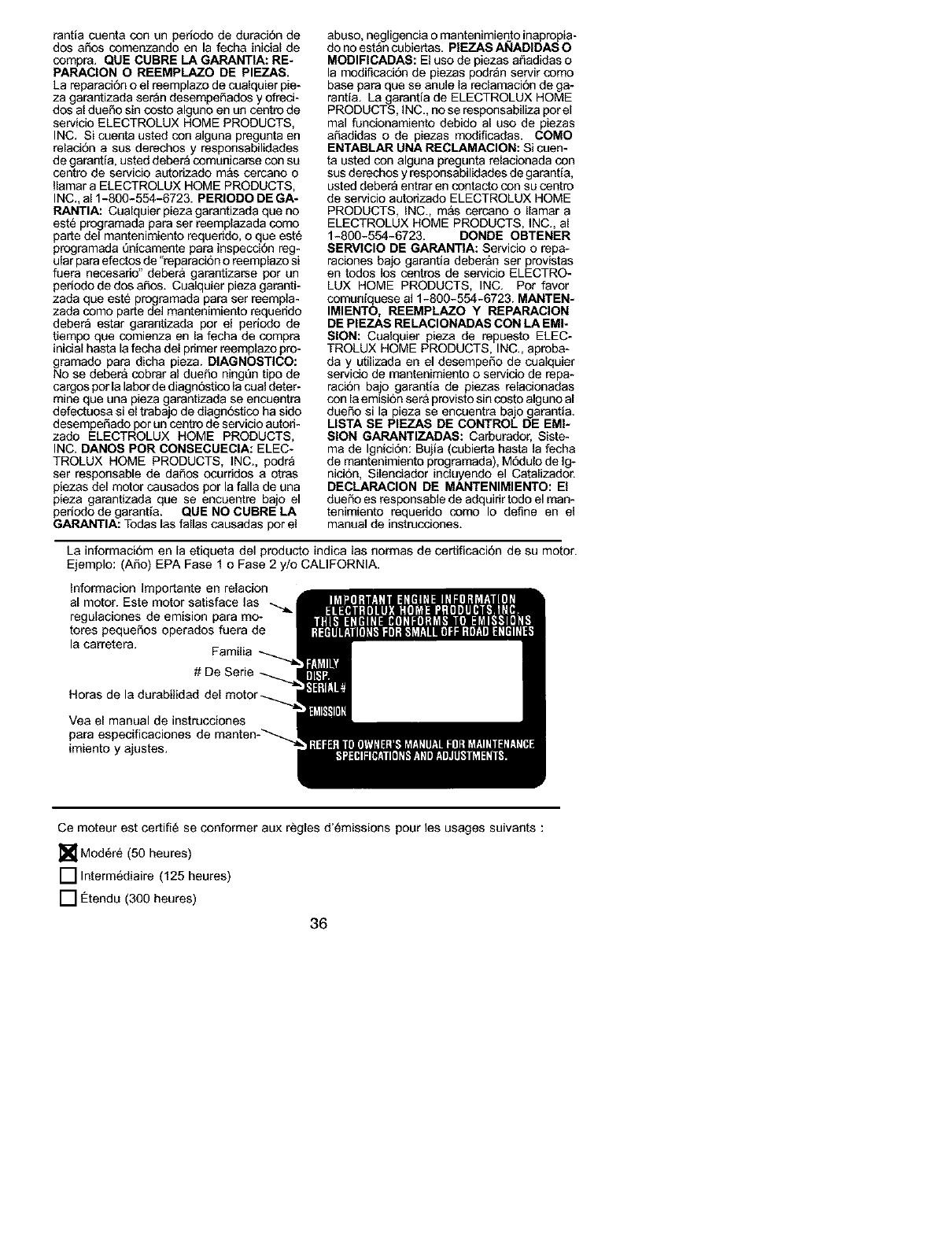
rantia cuenta con un pedodo de duraci6n de
dos aSos comenzando en la fecha inicial de
compra. QUE CUBRE LA GARANTIA: RE-
PARACION O REEMPLAZO DE PIEZAS.
La reparaei6n oel reemplazo de coalquier pie-
za garantizada ser_n desempe_ados yofreci-
dos al due_o sin costo alguno en un centre de
servicio ELECTROLUX HOME PRODUCTS,
INC. Si coenta usted con alguna pregunta en
relaci6n a sus derechos y responsabilidades
de garantia, usted deber_ comunicaree con su
centre de servicio a_orizado m&s cercano o
Ilamar a ELECTROLUX HOME PRODUCTS,
INC., al 1-800-554-6723. PERIODO DE GA-
RANTIA: Cualquier pieza garantizada que no
est_ programada para ser reemplazada como
parte del mantenimiento requerido, o que est6
programada _nicemente para inspecci6n reg-
ular para efectos de "reparaci6n o reemplazo si
fuera necesado" deber& garantizaree pot un
pedodo de dos aSos. Cualquier pieza garanti-
zada que este programada para ser reempla-
zada como parte del mantenimiento requerido
debera estar garantizada por el pedodo de
tiempo que comienza en la fecha de compra
inicial hasta la fecha del primer reemplazo pro-
gramado para dicha pieza. DIAGNOSTICO:
No se deber& cobrar al dueSo ningQn tipo de
cargos porla labor de diagn6stico la cual deter-
mine que una pieza garantizada se encuentra
defectuosa si el trabajo de diagn6stico ha sido
desempeSado por un centre de servicio autori-
zado ELECTROLUX HOME PRODUCTS,
INC. DANOS POR CONSECUECIA: ELEC-
TROLUX HOME PRODUCTS, INC., podra
ser responsable de dafLos ocurridos a otras
piezas del motor causados pot la falla de una
pieza garantizada que se encoentre ba o el
periodo de garantfa. QUE NO CUBRE LA
GARANTIA: Todas las fallas ceusadas por el
abuso, negligencia o mantenimiento inaprepia-
do no estan cubiertas. PIEZAS ANADIDAS O
MODIFICADAS: El uso de piezas afLadidas o
la modificeci6n de piezas podr_n servir come
base para que se anule la reclamaci6n de ga-
rantia. La garantia de ELECTROLUX HOME
PRODUCTS, INC., no se responsabiliza porel
mal funcionamiento debido al uso de piezas
a_adidas o de piezas modificadas. COMO
ENTABLAR UNA RECLAMACION: Si coen-
ta usted con alguna pregunta relacionada con
sus derechos y responsabilidades de garantfa,
usted deber_ entrar en contacto con su centre
de servicio autorizado ELECTROLUX HOME
PRODUCTS, INC., m&s cerceno o Ilamar a
ELECTROLUX HOME PRODUCTS, INC., al
1-800-554-6723. DONDE OBTENER
SERVICIO DE GARANTIA: Servicio o repa-
raciones bajo garantia deber&n ser provistas
en todos Ice centros de servicio ELECTRO-
LUX HOME PRODUCTS, INC. Pot favor
comuniquese al 1-800-654-6723. MANTEN-
IMIENTO, REEMPLAZO YREPARACION
DE PIEZAS RELACIONADAS CON LA EMI-
SION: Cualquier pieza de repuesto ELEC-
TROLUX HOME PRODUCTS, INC., aproba-
day L_ilizada en el desempeSo de cualquier
servicio de mantenimiento o servicio de repa-
recion bajo garantfa de piezas relacionadas
con la emision ser& previsto sin costo alguno al
dueSo si la pieza se encuentra bajo garantia.
USTA SE PIEZAS DE CONTROL DE EMI-
SION GARANTIZADAS: Carburador, Siste-
ma de Ignicidn: Bujia (cubierta hasta la fecha
de mantenimiento pregramada), M6dulo de Ig-
nicion, Silenciador induyendo el Catalizador.
DECLARACION DE MANTENIMIENTO: El
dueSo es responsable de adquirir todo el man-
tenimiento requerido come Io define en el
manual de instrucciones.
La informaci6m en la etiqueta del producto indice las normas de certificacion de su motor.
Ejemplo: (ASo) EPA Fase 1 o Fase 2 y/o CALIFORNIA.
Informacion Importante en relacion
al motor. Este motor satisface las
regulaciones de emision para mo-
tores pequeSos operados fuera de
la carretera. Familia
# De Serie
Horas de la durabilidad
Yea el manual de instrucciones
para especificeciones
imiento y ajustes.
Ce moteur est certifi6 se conformer aux regles d'_missions pour les usages suivants :
[]Mod6r_ (50 heures)
[] Interm6diaire (125 heures)
[] €:tendu (300 heures)
36
