Poulan 530164256 OM, PPB300, 2004 03, TRIMMERS/EDGERS User Manual To The Dfff11ac 9dcf 4d63 B1e0 Ae7a60124d5c
User Manual: Poulan 530164256 to the manual
Open the PDF directly: View PDF ![]() .
.
Page Count: 20

ENGLISH ESPAÑOL FRANÇAIS
DANGER:
Read and follow all Safety Rules and Operating Instructions before
using this product. Failure to do so can result in serious injury.
PELIGRO:
Lea el manual de instrucciones y siga todas las advertencias e
instrucciones de seguridad. El no hacerlo puede resultar en le-
siones graves.
DANGER:
Lire le manuel d’instructions et bien respecter tous les avertisse-
ments et toutes les instructions de sécurité. Tout défaut de le
faire pourrait entraîner des blessures graves.
Instruction Manual
Manual de Instrucciones
Manuel d’Instructions
PPB300
For Occasional Use Only
Electrolux Home Products, Inc.
104 Warren Road
Augusta, GA 30907
Copyright E2004 Electrolux Home Products, Inc. 530164256 3/11/04
R
2
UL CLASSIFIED PRODUCT NOTICE
Only the following Gasoline PoweredCombinationGardeningAppliance powerheadmodels
and their respective attachmentshave been Classified by UnderwritersLaboratories,Inc., in
accordance with the applicable safety requirements.
Powerhead including brushcutter/trimmer attachment PPB300..................
Optional blower attachment PPB3000B...........................................
Thefollowing attachment is Listed by Underwriter’s Laboratories,Inc., in accordance withUL
Standard 1602, “Gasoline--Engine--Powered, Rigid--Cutting Member, Edgers and Edge--
Trimmers.”
Optional edger attachment PPB1000E...........................................
SAFETY RULES
WARNING: When using gardening
appliances,basic safety precautions must al-
ways be followed to reduce the risk of fire and
serious injury.
DANGER: This power tool can be dan-
gerous! This unit can cause serious injury in-
cluding amputation or blindness to the operator
and others. The warnings and safety instruc-
tions in this manual must be followed to provide
reasonable safety and efficiency in using the
unit. The operator is responsible for following the
warnings and instructions in this manual and on
the unit. Read the entire instruction manual be-
fore assembling and using the unit! Restrict the
use of this unit to persons who read, under-
stand, and follow the warnings and instructions
in this manual and on the unit. Never allow chil-
dren to operate this unit.
SAFETY INFORMATION
ON THE UNIT
INSTRUCTION
MANUAL
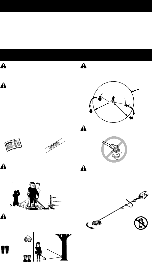
DANGER: Blade can thrust violently
away from material it does not cut. Blade thrust
can cause amputation of arms or legs. Keep
people and animals 50 feet (15 meters) away.
WARNING: Blade/trimmer line can
throw objects violently. You andothers can be
blinded or injured. Wear safety glasses and
leg protection.
Leg Guards
Boots
Eye
Protection
ALWAYS WEAR:
Thrown
Objects
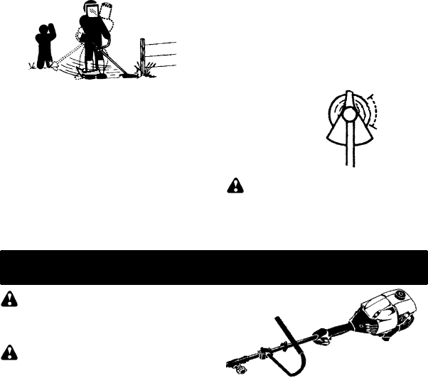
WARNING: Hazard zone for thrown
objects. Blade/trimmer line can throw objects vi-
olently. Others can be blinded or injured. Keep
people and animals 50 feet (15 meters) away.
Hazard Zone
50 Feet
(15 Meters)
WARNING: Do not use trimmer head
as a fastening device for the blade.
WARNING: The blade continues to
spin after the throttle is released or, engine is
turned off. The coasting blade can throw objects
or seriously cut if accidentally touched. Stop the
blade by contacting the right hand side of the
coasting blade with material already cut.
Stop coasting
blade by contact
with cut material.
OPERATOR SAFETY
SDress properly. Always wear safety
glasses or similar eye protection when op-
erating, or performing maintenanceon your
unit (safety glasses are available). Eye
protection should be marked Z87.
SAlways wear face or dust mask if operation
is dusty.

3
SAlways wear heavy, long pants, long sleeves,
boots, and gloves. Wearing safety leg guards
is recommended.
SAlways wear foot protection. Do not go
barefoot or wear sandals.
SSecure hair above shoulder length. Secure
or remove loose clothing and jewelry or cloth-
ing with loosely hanging ties, straps, tassels,
etc. They can be caught in moving parts.
SBeing fully covered also helps protect you
from debris and pieces of toxic plants
thrown by spinning line/blade.
SStay Alert. Do not operate unit when you are
tired, ill, upset or under influence of alcohol,
drugs, or medication. Watch what you are do-
ing; use common sense.
SWear hearing protection.
SNever start or run the engine inside a
closed room or building. Breathing exhaust
fumes can kill.
SKeep handles free of oil and fuel.
SAlways use the handlebar and a properly
adjusted shoulder strap with a blade (see
ASSEMBLY).
UNIT/MAINTENANCESAFETY
WARNING: Stop unit and disconnect
the spark plug before performing mainte-
nance (except carburetor adjustments).
SLook for and replace damaged or loose
parts before each use. Look for and repair
fuel leaks before use. Keep unit in good
working condition.
SThrow away blades that are bent, warped,
cracked, broken, or damaged in any other
way. Replace trimmer head parts that are
cracked, chipped, broken, or damaged in
any other way before using the unit.
SMaintain unit according to recommended
procedures. Keep blade sharp. Keep cut-
ting line at the proper length.
SUse only 0.080!(2 mm) diameter Poulan
PRO"brand replacement line. Never use
wire, rope, string, etc.
SInstall required shield properly before using
the unit. Use the metal shield for all metal
blade use. Use the plastic shield for all line
trimmer use.
SUse only specified blade or trimmer head;
make sure it is properly installed and se-
curely fastened.
SNever start engine with clutch shroud re-
moved. The clutch can fly off and cause se-
rious injury.
SBe sure bladeor trimmerhead stops turning
when engine idles.
SMake carburetor adjustments with the low-
er end supported to prevent blade or trim-
mer line from contacting any object. Hold
unit by hand; do not use the shoulder strap
for support.
SKeep others away when making carburetor
adjustments.
SUse only recommended Poulan PROrac-
cessories and replacement parts.
SHave all maintenance and service not ex-
plained in this manual performed by your au-
thorized service dealer.
FUEL SAFETY
SMix and pour fuel outdoors.
SKeep away from sparks or flames.
SUse a container approved for fuel.
SDo not smoke or allow smoking near fuel or
the unit or while using the unit.
SAvoid spilling fuel or oil. Wipe up all fuel
spills before starting engine.
SMove at least 10 feet (3 meters) away from
fueling site before starting engine.
SStop engine and allow it to cool before re-
moving fuel cap.
SEmpty the fuel tank before storing or trans-
porting the unit. Use up fuel left in the car-
buretor by starting the engine and letting it
run until it stops.
SStore unit and fuel in area where fuel vapors
cannot reach sparks or open flames from
water heaters, electric motors or switches,
furnaces, etc.
SAlways store gasoline in a container ap-
proved for flammable liquids.
CUTTING SAFETY
WARNING: Inspect the area to be
cut beforeeach use. Remove objects (rocks,
broken glass, nails, wire, string, etc.) which
can be thrown or become entangled in the
blade or trimmer head.
SKeep others including children, animals,
bystanders, andhelpers at least 50 feet (15
meters) away. Stop engine immediately if
you are approached.
SAlways keep engine on the right--handside
of your body.
SHold the unit firmly with both hands.
SKeep firm footing and balance. Do not over-
reach.
SKeep blade or trimmer head below waist
level. Do not raise engine above your waist.
SKeep all parts of your body away from
blade, trimmer head, and muffler when en-
gine is running. A hot mufflercan causese-
rious burns.
SCut from your left to your right. Cutting on
right side of the shield will throw debris
away from the operator.
SUse only in daylight or good artificial light.
SUse only for jobs explained in this manual.
TRANSPORTINGAND STORAGE
SStop the unit before carrying.
SKeep muffler away from your body.
SAllow the engine to cool and secure the unit
before storing or transporting it in a vehicle.
SEmpty the fuel tank before storing or trans-
porting the unit. Use up fuel left in the carbu-
retor by starting the engine and letting it run
until it stops.
SStore unit so the blade or line limiter blade
cannot accidentally cause injury. The unit
can be hung by the shaft.
SStore unit out of reach of children.
SAFETY NOTICE: Exposure to vibrations
through prolonged use of gasoline powered
hand tools could cause blood vessel or nerve
damage in the fingers, hands, and joints of
people prone to circulation disorders or abnor-
mal swellings. Prolonged use in cold weather
has been linked to blood vessel damage in
4
otherwise healthy people. If symptoms occur
such as numbness, pain, loss of strength,
change in skin color or texture, or loss of feeling
in the fingers, hands, or joints, discontinue the
use of this tool and seek medical attention. An
anti--vibration system does not guarantee the
avoidance of these problems. Users who oper-
ate power tools on a continual and regular basis
must monitor closely their physical condition
and the condition of this tool.
SPECIAL NOTICE: This unit is equipped
with a temperature limiting muffler and spark
arresting screen which meets the require-
ments of California Codes 4442and 4443. All
U.S. forest land and the states of California,
Idaho, Maine, Minnesota, New Jersey, Ore-
gon, and Washington require by law that
many internal combustion engines be
equippedwitha spark arrestingscreen. If you
operatein alocale wheresuch regulations ex-
ist, you are legally responsible for maintaining
the operating condition of these parts. Failure
to do so is a violation of the law. For normal
homeowner use, the muffler and spark arrest-
ing screen will not require any service. After
50 hours of use, we recommend that your
muffler beserviced orreplaced by your autho-
rized service dealer.
ASSEMBLY
CARTON CONTENTS
Check carton contents against the following
list:
SPowerhead
SLower attachment (with trimmer head
installed)
SCupped washer
SLarge nut for installing blades
SHex wrench
SHandlebar
SBracket cover
SBracket cover screws (2)
SMetal blade shield
SBlade shield screws (4)
S4--point weed blade
SPlastic shield
SWing nut (screwed onto plastic shield)
SShoulder strap with warning
SContainer of oil
WARNING: Always stop unit and dis-
connect spark plug before performingany as-
sembly procedures.
WARNING: If received assembled,
repeat all steps to ensure your unit is properly
assembled and all fasteners are secure.
Examine parts for damage. Do not use dam-
aged parts.
NOTE: If you need assistance or find parts
missing or damaged, call 1-800-554-6723.
It is normal for the fuel filter to rattle in the
empty fuel tank.
Finding fuel or oil residue on muffler is normal
due to carburetor adjustments and testing
done by the manufacturer.
TOOLS REQUIRED
SHex wrench (provided)
SAdjustable wrench
SPhillips screwdriver
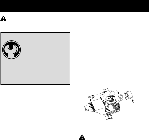
INSTALLING BRUSHCUTTER
ATTACHMENT
CAUTION: When installing brushcutter at-
tachment, place the unit on a flat surface for
stability.
1. Loosen the coupler by turning the knob
counterclockwise.
Coupler
Knob
LOOSEN
TIGHTEN
Shipping
protector
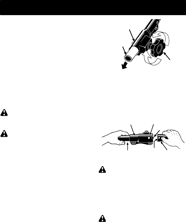
2. Remove shipping protector from coupler.
3. Remove the shaft cap from the brushcutter
attachment (if present).
4. Position locking/release button of attach-
ment into guide recess of coupler.
5. Push the attachmentintothe coupler until
the locking/release button snaps into the
primary hole.
6. Before using the unit, tighten the knob se-
curely by turning clockwise.
Coupler Primary Hole
Upper
Shaft
Locking/
Release
Button
Lower
Attachment
Guide Recess
WARNING: Make sure the locking/
release button is locked in the primary hole
and the knob is securely tightened before op-
erating the unit. All attachments are designed
to be used in the primary hole.
For optional attachments, see the AS-
SEMBLY section of the applicable attach-
ment instruction manual.
ATTACHING THE HANDLEBAR
DANGER: To avoid serious injury, the
barrier portion of the handlebar must be installed
as shown to provide a barrier between operator
and the spinning blade.
1. Locate the decal on the handlebar. This
decal includes an arrow. Position the
handlebar with the mounting bracket at
the end of the arrow.
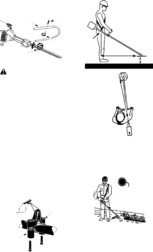
5
2. Position the bracket cover over the han-
dlebar. Again make sure the handlebar is
at the end of the arrow.
3. Insert screws and hand tighten only. Be
sure the handlebar is installed correctly;
then, tighten each screw securely with
the hex wrench.
Screw
Mounting
Bracket
Handlebar
Bracket Cover
ASSEMBLY OF SHOULDER STRAP
WARNING: Proper shoulder strap
and handlebar adjustments must be made
with the engine completely stopped before
using unit.
1. Insert your right arm and head through
the shoulder strap and allow it to rest on
your left shoulder. Make sure the danger
sign is on your back and the hook is to the
right side of your waist.
NOTE: A one-half twist is built in the shoul-
der strap to allow the strap to rest flat on the
shoulder.
2. Adjust the strap, allowing the hook to be
about 6 inches (15 cm) below the waist.
3. Fasten the strap hook to the clamp located
between the trigger handle and the handle-
bar clamp base and lift the tool to the oper-
ating position.
4. Try on shoulder strap and adjust for fit
and balance before starting the engine or
beginning a cutting operation.
NOTE: It may be necessary to relocate the
shoulder strap clamp on the shaft for proper
balancing of unit.
TO RELOCATE SHOULDER STRAP
CLAMP:
1. Loosen and remove both clamp screws.
2. Place the upper shoulder strap clamp
over the shaft.
3. Position the lower shoulder strap clamp
under the shaft and align the upper and
lower clamp screw holes.
Upper Shoulder
Strap Clamp
Screws
Lower Shoulder
Strap Clamp
4. Insert two screws into the screw holes.
5. Secure shoulder strap clamp by tighten-
ing screws with a hex wrench.
30 inches
(76 cm)
HARNESS
ADJUSTMENT
FOR BALANCE
4 -- 12 inches
(10 -- 30 cm)
above
ground
6 inches
(15 cm)
below
waist
30 inches
(76 cm)
CONFIGURING YOUR UNIT
You can configure your unit using a cuttinghead
for grass and light weeds, or a weed blade for
cutting grass, weeds, and brush up to 1/2 inch
(1 cm) in diameter. To assemble your unit, go to
the section for the desired configuration and fol-
low the instructions.
ASSEMBLY INFORMATION --
TRIMMER HEAD
TRIMMER
HEAD
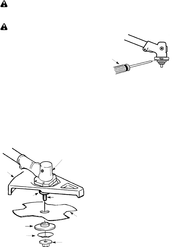
NOTE: Remove the blade and metal shield be-
fore attaching the plastic shield and trimmer
head. To remove blade, align hole in the dust
cup with the hole in the side of the gearbox by
rotating the blade. Insert a small screwdriver
into aligned holes. This will keep the shaft from
turning while loosening the blade nut. Remove
blade nut by turning clockwise. Remove the
6
screwdriver. Remove both washers and blade.
To remove metal shield, loosen and remove the
four mounting screws. See ATTACHING THE
METAL SHIELD and INSTALLATION OF THE
METAL BLADEfor illustrations. Besure to store
all parts and instructions for future use.
ATTACHING THE PLASTIC SHIELD
AND TRIMMER HEAD
WARNING: The shield must be prop-
erly installed. The shield provides partial
protection to the operator and others from the
risk of thrown objects, and is equipped with a
line limiter blade whichcuts excess line to the
proper length. The line limiter blade (on un-
derside of shield) is sharp and can cut you.
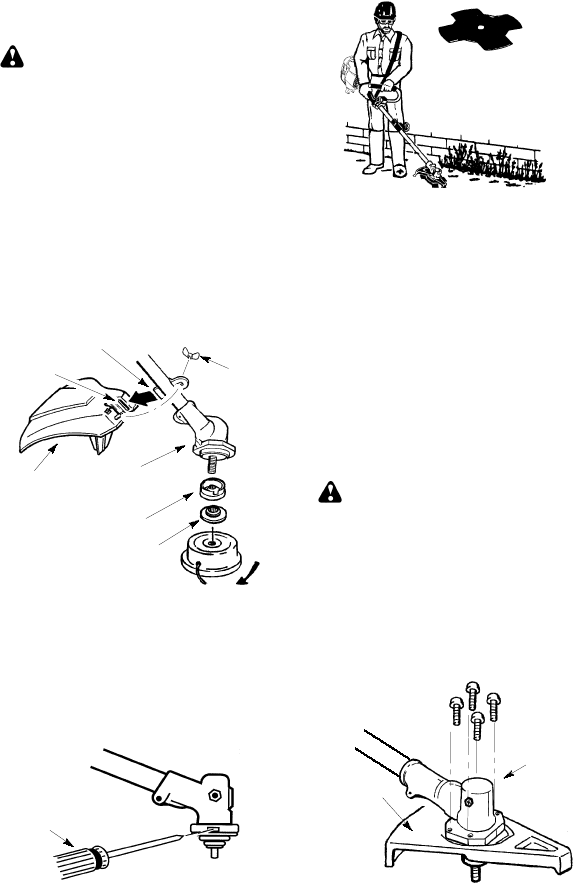
1. Remove wing nut from shield.
2. Insert bracket into slot on shield.
3. Pivot shield until bolt passes through hole
in bracket.
4. Tighten the wing nut securely.
NOTE: If your unit has a plastic cover over
the threads on the threadedshaft, remove the
covering to expose the threads. Before instal-
ling the trimmer head, make sure the dust cup
and retaining washer are positioned on the
gearbox as shown below.
Wing Nut
Retaining Washer
Dust Cup
Bracket
Slot
Shield Gearbox
NOTE: Make sure all parts are properly
installed as shown in the illustration before
installing the trimmer head.
5. Align hole in the dust cup with the hole in
the side of the gearbox by rotating the
dust cup.
6. Insert a small screwdriver into aligned
holes. This will keep the shaft from turn-
ing while tightening trimmer head.
Screwdriver
7. While holding the screwdriver in position,
thread trimmer head onto the shaft in the
direction shown on the decal (counter-
clockwise). Tighten until secure.
NOTE: The retaining washer must be posi-
tioned with the raised section facing toward the
gearbox.
ASSEMBLY INFORMATION -- WEED
BLADE
WEED
BLADE
NOTE: Remove the trimmer head and plastic
shield before attaching the metal shield and
installing the weed blade. To remove the trim-
mer head, align hole in the dust cup with the hole
in the side of the gearbox by rotating the dust
cup. Insert a small screwdriver into aligned
holes. This will keep the shaftfrom turningwhile
loosening the trimmer head. Remove the trim-
mer head by turning clockwise. Remove the
screwdriver. To remove the plastic shield, loos-
en and remove wing nut. Pivot shield to release
bracket from slot. See INSTALLATION OF
THECUTTINGHEADandATTACHINGTHE
PLASTIC SHIELD for illustrations. Be sureto
store all parts and instructions for future use.
Never use the trimmer head with the metal
blade installed.
ATTACHING THE METAL SHIELD
WARNING: The metal shield must
be properly installed on the tool anytime the
tool is used with a blade.The forwardtip of the
metal shield helps to reduce the occurrence
of blade thrust which can cause serious injury
such as amputation to the operator or by-
standers. Failure to install the shield in the
position shown can result in serious injury to
the operator. The length of the shield must be
aligned with the length of the shaft.
1. Place the metal shield under the gearbox,
and align the screw holes.
Shield
Gearbox
2. Insert and thread the 4 mounting screws
through the holes of the gearbox and the
metal shield. Tighten evenly and secure-
ly with the hex wrench provided.
7
INSTALLATION OF THE METAL
BLADE
WARNING: Wear protective gloves
when handling or performing maintenance on
the blade to avoid injury. The blade is sharp and
cancutyouevenwhenitisnotmoving.
WARNING: Do not use any blades, or
fastening hardware other than the washers and
nuts shown in the following illustrations. These
parts must be provided by Poulan/Weed Eater
and installed as shown below. Failure to use
proper parts can cause the blade to fly off and
seriously hurt you or others.
NOTE: The dust cup and retaining washer are
located on the gearbox shaft and not in the parts
bag. All other fasteners mentioned in the follow-
ing assembly steps are in the parts bag.
1. Remove the retaining washer from the
threaded shaft of the gearbox. Leavethe
dust cup on the shaft.
2. Install the blade and the retaining washer
over the threaded shaft.
3. Make sure the raised part of the retaining
washer is facing the gearbox and the
raised area fits into the hole in the center
of the blade.
4. Slide the blade and retaining washer onto
the shaft of the gearbox.
5. Place the cupped washer onto the shaft.
Make sure the cupped side of the washer
is toward the blade.
6. Install the blade nut by threading onto the
shaft counterclockwise.
Shield
Blade
Retaining
Washer
Dust Cup
Cupped
Washer Nut
Threaded Shaft
Gearbox
NOTE: Make sure all parts are in place as il-
lustrated, and the blade is sandwiched between
the dust cup and the retaining washer. There
should be no space between the blade and the
dust cup or the retaining washer.
7. Align hole in dust cup with hole in side of
gearbox by rotating the blade.
8. Insert a small screwdriver into aligned
holes. This will keep the shaft from turn-
ing while tightening the blade nut.
Screwdriver
9. TIghten blade nut firmly with a wrench while
holding screwdriver in position.
10. Remove the screwdriver.
11. Turn blade by hand. If the blade binds
against theshield, or appears to be uneven,
the blade is not centered, and you must re-
install.
NOTE: To remove blade, insert screwdriver
into aligned holes. Unthread the nut and re-
move parts. Be sure to store parts and instruc-
tions for future use.
8
OPERATION
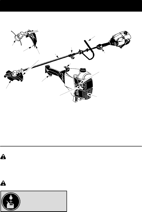
KNOW YOUR UNIT
READ THIS INSTRUCTION MANUAL AND SAFETY RULES BEFORE OPERATING YOUR UNIT.
Compare the illustrations with your unit to familiarize yourself with the location of the various controls
and adjustments. Save this manual for future reference.
Line Limiter
Blade
Primer Bulb
Handlebar
Starter Handle
Throttle Trigger
Choke
Lever
Shield
Trimmer Head Shaft
Muffler
ON/OFF Switch
Coupler
Blade
ON/OFF SWITCH
The ON/OFF switch is located on the trigger
handle and is used to stop the engine. Move the
switch to the OFF position to stop the engine.
PRIMER BULB
The PRIMER BULBremoves air from the car-
buretor and fuel lines and fills them with fuel.
This allows you to start the engine with fewer
pulls on the starter rope. Activate the primer
bulb by pressing it and allowing it to return to
its original form.
CHOKE
The CHOKE helps to supply fuel to the engine
to aid in cold starting. Activate the choke by
moving the choke lever to the FULL CHOKE
position. After the engine attempts to start, move
the choke lever to the HALF CHOKE position.
Once engine has started, move the choke lever
to the OFF CHOKE position.
COUPLER
The COUPLER enables optional attach-
ments to be installed on the unit.
BEFORE STARTING ENGINE
WARNING: Be sure to read the fuel
information in the safety rules before you be-
gin. If you do not understand the safety rules,
do not attempt to fuel your unit. Call
1-800-554-6723.
FUELING ENGINE
WARNING: Remove fuel cap slowly
when refueling.
HELPFUL TIP
To obtain the correct oil mix
ratio, pour 3.2 ounces of
2--cycle synthetic oil into
one gallon of fresh gas.
This engine is certified to operate on un-
leaded gasoline. Before operation, gasoline
must be mixed with a good quality synthetic
2-cycle air-cooled engine oil designed to be
mixed at a ratio of 40:1. Poulan/Weed Eater
brand synthetic oil is recommended. Mix gaso-
line and oil at a ratio of 40:1. A 40:1 ratio is ob-
tainedby mixing 3.2 ounces (95 ml) of oil with1
gallon (4 liters) of unleaded gasoline. DO NOT
USE automotive oil or marine oil. These oils
will cause engine damage. When mixing fuel,
follow instructions printedoncontainer. Once
oil is added to gasoline, shake container mo-
mentarily to assure that the fuel is thoroughly
mixed. Always read and follow the safety
rules relating to fuel before fueling your unit.
IMPORTANT
Experience indicates that alcohol blended
fuels (called gasohol or using ethanol or
methanol) can attract moisture which leads to
separation and formation of acids during stor-
age. Acidic gas can damage the fuel system
of an engine while in storage. To avoid engine
problems, empty the fuel system before stor-
age for 30 days or longer. Drain the gas tank,
start the engine and let it run until the fuel lines
and carburetor are empty. Use fresh fuel next
season. Never use engine or carburetor
cleaner products in the fuel tank or permanent
damage may occur.
See the STORAGE section for additional in-
formation.
HOW TO STOP YOUR UNIT
STo stop the engine, move the ON/OFF
switch to the OFF position.
SIf engine does not stop, move choke lever
to FULL CHOKE position.
9
Throttle Trigger
ON/OFF
Switch
HOW TO START YOUR UNIT
WARNING: Avoid any contact with
the muffler. A hot muffler can cause serious
burns.
HELPFUL TIP
If your engine still does not
start after following these
instructions, please call
1--800--554--6723.
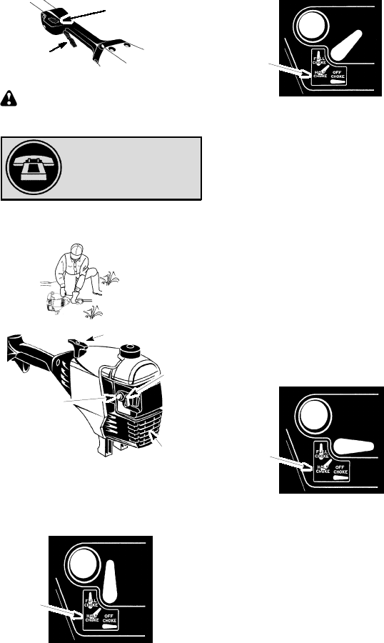
STARTING A COLD ENGINE (or a
warm engine after running out of
fuel)
Starting Position
Muffler
Choke
Lever
Starter Handle
Primer Bulb
1. Set unit on a flat surface.
2. Move ON/OFF switch to the ON position.
3. Slowly press the primer bulb 6 times.
4. Move choke lever to FULL CHOKE by
aligning lever with position shown on de-
cal (see illustration below).
Choke
position
decal
5. Squeeze the throttle trigger fully and hold
through all remaining steps.
6. Pull starter rope handle sharply until en-
gine sounds as if it is trying to start, butdo
not pull rope more than 6 times.
7. As soon as engine sounds as if it is trying
to start, move choke lever to HALF
CHOKE by aligning lever with position
shown on decal (see illustration below).
Choke
position
decal
8. Pull starter rope sharply until engine runs,
but no more than 6 pulls. If the engine
doesn’t start after 6 pulls (at the HALF
CHOKE position), move the choke lever to
the FULL CHOKE position and press the
primer bulb 6 times. Squeeze and hold the
throttle trigger and pull the starter rope 2
more times. Move the choke lever to the
HALF CHOKE position and pull the starter
rope until the engine runs, but no more than
6 pulls. If the engine doesn’t start, repeat
procedure 2 additional times.
NOTE: If engine still doesn’t start, it is
probably flooded. Proceed to STARTING A
FLOODED ENGINE.
9. Oncetheenginestarts,allowittorun10se-
conds, then move the choke lever to OFF
CHOKE by aligning lever with position
shown on decal (see illustration below). Al-
low the unit to run for 30 more seconds at
OFF CHOKE before releasing the throttle
trigger. NOTE: If engine dies with the
choke lever in the OFF CHOKE position,
move the choke lever to the HALF CHOKE
position and pull the rope until engine runs,
but no more than 6 pulls.
Choke
position
decal
STARTING A WARM ENGINE
1. Move ON/OFF switch to the ON position.
2. Move the choke lever to the HALF
CHOKE position.
3. Squeeze and hold the throttle trigger.
Keep throttle trigger fully squeezed until
the engine runs smoothly.
4. Pull starter rope sharply until engine runs,
but no more than 5 pulls.
5. Allow engine to run 15 seconds, then
move the choke lever to the OFF CHOKE
position.
NOTE:If engine has not started, pull starter
rope 5 more pulls. If enginestill does not run, it
is probably flooded.
STARTING A FLOODED ENGINE
Flooded engines can be started by placing
the choke lever in the OFF CHOKE position;
then, pull the rope to clear the engine of ex-
cess fuel. This could requirepulling thestarter
handle many times depending on how badly
the unit is flooded.
10
If the unit still doesn’t start, refer to
TROUBLESHOOTING TABLE or call
1-800-554-6723.
OPERATING THE COUPLER
This model is equipped with a coupler which
enables optional attachments to be installed.
The optional attachments are: MODEL:
Edger PPB1000E.....................
Cultivator PPB2000T..................
Blower PPB3000B....................
Pruner PP5000P....................
WARNING: Always stop unit and dis-
connect spark plug before removing or instal-
ling attachments.
REMOVING TRIMMER ATTACH-
MENT (OR OTHER OPTIONAL
ATTACHMENTS)
CAUTION: When removing or installing at-
tachments, place the unit on a flat surface for
stability.
1. Loosen the coupler by turning the knob
counterclockwise.
Coupler
Knob
LOOSEN
TIGHTEN
Upper Shaft
Lower
Attachment
2. Press and hold the locking/release button.
Locking/Release
Button
Coupler Upper Shaft
Lower Attachment
3. While securely holding the engine and
upper shaft, pull the attachment straight
out of the coupler.
INSTALLING OPTIONAL ATTACH-
MENTS
1. Remove the shaft cap from the attach-
ment (if present).
2. Position locking/release button of attach-
ment into guide recess of coupler.
3. Push the attachmentintothe coupler until
the locking/release button snaps into the
primary hole.
4. Before using the unit, tighten the knobse-
curely by turning clockwise.
Coupler Primary Hole
Upper
Shaft
Locking/
Release
Button
Attachment
Guide Recess
WARNING: Make sure the locking/
release button is locked in the primary hole
and the knob is securely tightened before op-
erating the unit.
OPERATING INSTRUCTIONS
It is recommended that the engine not be
operated for longer than 1 minute at full
throttle.
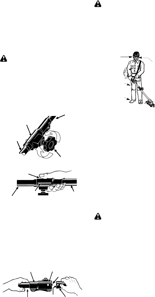
OPERATING POSITION
Boots
Heavy,
Long Pants
Eye Protection
ALWAYS WEAR:
Cut from your left to your right.
Hearing
Protection
When operating unit, clip shoulder strap onto
clamp, stand as shown and check for the fol-
lowing:
SWear eye protection and heavy clothing.
SExtend your left arm and hold handlebar
grip with your left hand.
SHold throttle grip with your right hand with
finger on throttle trigger.
SKeep unit below waist level.
SKeep shoulder strap pad centered on your
left shoulder and danger sign centered on
your back.
SMaintain full weight of tool on your left
shoulder.
SWithout bending over, keep the blade or
trimmer head near and parallel to the
ground andnot crowdedinto material being
cut.
OPERATING INSTRUCTIONS FOR
USE WITH TRIMMER HEAD
WARNING: Always wear eye protec-
tion. Never lean over the trimmer head. Rocks
or debris can ricochet or be thrown into eyes
and face and cause blindness or other serious
injury.
Beforetrimming, bring engineto a speed suffi-
cient to cut material to be trimmed.
Do not run the engine at a higher speed than
necessary. The cutting line will cut efficiently
when the engine is run at less than full throttle.
At lower speeds, there is less engine noise and
vibration. The cutting line will last longer and will
be less likely to “weld” onto the spool.
Always release the throttle trigger and allow
the engine to return to idle speed when not
cutting.
To stop engine:
SRelease the throttle trigger.
SMove the ON/OFF switch to the OFF posi-
tion.
11
TRIMMER LINE ADVANCE
Thetrimmerline will advanceapproximately 2
inches (5 cm) each time the bottom of the
trimmer head is tapped on the groundwith the
engine running at full throttle.
The most efficient line length is the maximum
length allowed by the line limiter. Always keep
the shield in place when the tool is being oper-
ated.
To advance line:
SOperate the engine at full throttle.
SHold the trimmer head parallel to and above
the grassy area.
STap the bottom of the trimmer head lightly on
the ground one time. Approximately 2 inches
(5 cm) of line will be advanced with each tap.
Always tap the trimmer head on a grassy area.
Tapping on surfaces such as concrete or as-
phalt can cause excessive wear to the trimmer
head.If the line is worn down to 2 inches (5 cm)
or less, more than one tap will be required to ob-
tain the most efficient line length.
WARNING: Use only 0.080!(2 mm)
diameter line. Other sizes of line will not ad-
vance properly and can cause serious injury.
Do not use other materials such as wire,
string, rope, etc. Wire can break off during
cutting and become a dangerous missile that
can cause serious injury.
CUTTING METHODS
WARNING: Use minimum speed
and do not crowd the line when cutting around
hard objects (rock, gravel, fence posts, etc.),
which candamagethe trimmer head,become
entangled in the line, or be thrown causing a
serious hazard.
SThe tip of the line does the cutting. You will
achieve the best performance and mini-
mum line wear by not crowding the line into
the cutting area. The right and wrong ways
are shown below.
Tip of the line
does the cutting.
Right Wrong
Line crowded into
work area.
SThe line will easily remove grass and
weeds from aroundwalls, fences, trees and
flower beds, but it also can cut the tender
bark of trees or shrubs and scar fences.
SFor trimming or scalping, use less than full
throttle to increase line life and decrease
head wear, especially:
SDuring light duty cutting.
SNear objects around which the line can
wrap such as small posts, trees or fence
wire.
SFor mowing or sweeping, usefull throttlefor
a good clean job.
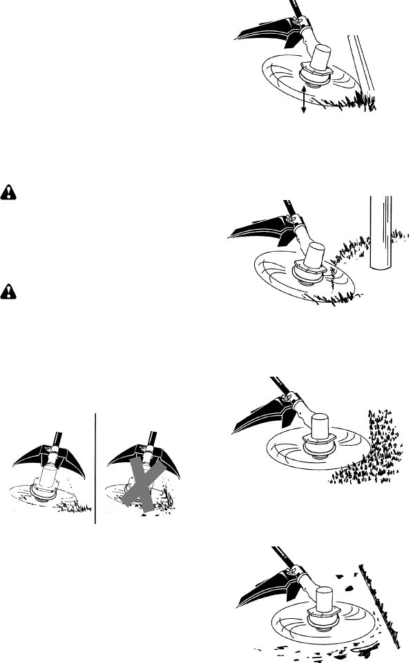
TRIMMING -- Hold the bottom of the trimmer
head about 3 inches (8 cm) above the ground
and at an angle. Allow only the tip of the line to
make contact. Do not force trimmer line into
work area.
Trimming
3 inches (8 cm)
above ground
SCALPING -- The scalping technique removes
unwanted vegetation down to the ground. Hold
the bottom of the trimmer head about 3 in. (8
cm) above the ground and at an angle. Allow the
tip of the line to strike the ground around trees,
posts, monuments, etc. This technique in-
creases line wear.
Scalping
MOWING -- Your trimmer is ideal for mowing
in places conventional lawn mowers cannot
reach. In the mowing position, keep the line
parallel to the ground. Avoid pressing the
head into the ground as this can scalp the
ground and damage the tool.
Mowing
SWEEPING -- The fanning action of the rotat-
ing line can be used to blow away loose debris
from an area. Keep the line parallel to and
above the area surface and swing the tool
from side to side. Sweeping
12
OPERATING INSTRUCTIONS FOR
USE WITH WEED BLADE
SBlade Thrust is a reaction that only occurs
when using a bladed unit. This reaction can
cause serious injury such as amputation.
Carefully study this section. It is importantthat
you understand what causes blade thrust,
how you can reduce the chance of its
occurring, and how you can remain in control
of unit if blade thrust occurs.
SWHAT CAUSES BLADE THRUST -- Blade
Thrust can occur when the spinning blade
contacts an object that it does not cut. This
contact causes the blade to stop for an instant
and then suddenly move or “thrust” away
from the object that was hit. The “thrusting”
reaction can be violent enough to cause the
operator to be propelled in any direction and
lose control of the unit. The uncontrolled unit
can cause serious injury if the blade contacts
the operator or others.
SWHEN BLADE THRUST OCCURS --
Blade Thrust can occur without warning if
the blade snags, stalls, or binds. This is
more likely to occur in areas where it is
difficult to see the material being cut. By
using the unit properly, the occurrence of
blade thrust will be reduced and the
operator will be less likely to lose control.
SCut only grass, weeds, andwoody brushup
to 1/2 inch (1 cm) in diameter with the weed
blade. Do not let the blade contact material
it cannot cut such as stumps, rocks,
fences, metal, etc., or clusters of hard,
woody brush having a diameter greater
than 1/2 inch (1 cm).
SKeep the blade sharp. A dull blade is more
likely to snag and thrust.
SCut only at full throttle. The blade will have
maximum cutting powerand is less likely to
bind or stall.
S“Feed” the blade deliberately and not too
rapidly. The bladecan thrustaway if it is fed
too rapidly.
SCut only from your left to your right. Cutting on
right side of the shield will throw debris away
from the operator.
SUse the shoulder strap and keep a firm grip
on the unit with both hands. A properly
adjusted shoulder strap will support the
weight of the unit, freeing your arms and
hands to control and guide the cutting motion.
SKeep feet comfortably spread apart and
braced for a possible sudden, rapid thrust of
unit. Do not overreach. Keep firm footing and
balance.
SKeep blade below waist level; it will be
easier to maintain control of unit.
SDo not raise the engine aboveyour waist as
the blade can come dangerously close to
your body.
SDo not swing unit with such force that you
are in danger of losing your balance.
Bring the engine to cutting speed before enter-
ing the material to be cut.If the blade does not
turn when you squeeze the throttle trigger, make
sure shaft is fully inserted into the engine.
Always release the throttle trigger and allow
engine to return to idle speed when not cut-
ting. The blade should not turn while the en-
gine is running at idle. If the bladeturns at idle,
do not use your unit. Refer to theCARBURE-
TOR ADJUSTMENT section or contact your
authorized service dealer.
SMaintain good firm footing while using the
unit. Do this by planting feet firmly in a
comfortable apart position.
SCut while swinging the upper part of your
body from left to right.
SAs you move forward to the next area to cut,
be sure to maintain your balance and footing.
Cut using the 2
o’clock to 4 o’clock
position of the
blade
2 o’clock
4 o’clock
RECOMMENDED CUTTING POSITION
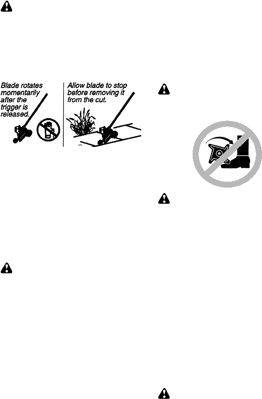
WARNING: The operator or others
must not try to clear away cut material with the
engine running or the blade turning to avoid
serious injury. Stop engine and blade before
removing materials wrapped around blade or
shaft.
ADDITIONAL SAFETY RULES
FOR OPTIONAL ATTACHMENTS
WARNING: For each optional at-
tachment used, read entire instruction manu-
al before use and follow all warnings and in-
structions in manual and on attachment.
WARNING: Ensure handlebar re-
mains installed on upper shaft (engine end of
unit) at all times.
Handlebar
13
EDGER SAFETY
WARNING: Inspect the area to be
edged before each use. Remove objects
(rocks, broken glass, nails, wire, etc.) which
can be thrown by the blade or can wrap
around the shaft.
SBlade rotates momentarily after the trigger
is released. The blade can seriously cut
you or others.
SAllow blade to stop before removing it from
the cut.
SThrow away blades that are bent, warped,
cracked, broken or damaged in any other
way. Replace parts that are cracked,
chipped, or damaged before using the unit.
SDo not attempt to remove cut material nor
hold material to be cut when the engine is
running or when cutting blade is moving.
SAlways keep the wheel and depth adjusting
skid in contact with the ground.
SAlways push the unit slowly over the
ground. Stay alert for uneven sidewalks,
holes in the terrain, large roots, etc.
SAlways use the handlebar when using
edger attachment.
BLOWER/VACUUM SAFETY
WARNING: Inspect area before
starting unit. Remove all debris and hard ob-
jects such as rocks, glass, wire, etc. that can
ricochet, be thrown, or otherwise cause injury
or damage during operation.
SDo not set unit on any surface except a clean,
hard area while engine is running. Debris
such as gravel, sand, dust, grass, etc., could
be picked up by the air intake and thrown out
through discharge opening, damaging unit,
property, or causing serious injury to
bystanders or operator.
SNever place objects inside the blower tubes,
vacuum tubes or blower outlet. Always direct
the blowing debris away from people,
animals, glass, and solid objects such as
trees, automobiles, walls, etc. The force of air
cancause rocks, dirt, or sticks tobe thrownor
to ricochet which can hurt people or animals,
break glass, or cause other damage.
SNever run unit without the proper
equipment attached. When using your unit
as a blower, always install blower tubes.
SCheck air intake opening, blower tubes or
vacuum tubes frequently, always with
engine stopped and spark plug
disconnected. Keep vents and discharge
tubes free of debris which can accumulate
and restrict proper air flow.
SNever place any object in air intake opening
as this could restrict proper air flow and cause
damage to the unit.
SNever use for spreading chemicals, fertilizers,
or other substances which may contain toxic
materials.
STo avoid spreading fire, do not use near leaf or
brush fires, fireplaces, barbecue pits,
ashtrays, etc.
CULTIVATOR SAFETY
WARNING: Rotating tines can cause
serious injury. Keep away from rotating tines.
Stop the engine and disconnect the spark plug
before unclogging tines or making repairs.
WARNING: Inspect the area to be
cultivated before starting the unit. Remove all
debris and hard and sharp objects such as
rocks, vines, branches, rope, string, etc.
SAvoid heavy contact with solid objects that
might stop the tines. If heavy contact occurs,
stop the engine and inspect the unit for
damage.
SNever operate the cultivator without the tine
cover in place and properly secured.
SKeep the tines and guard clear of debris.
SAfter striking a foreign object, stop the
engine, disconnect the spark plug and
inspect the cultivator for damage. Repair
before restarting.
SDisconnect attachment from the drive engine
before cleaning the tines with a hose and
water to remove any build--up. Oil the tines to
prevent rust.
SAlways wear gloves when servicing or
cleaning the tines. The tines become very
sharp from use.
SDo not run unit at high speed unless
cultivating.
HEDGE TRIMMER SAFETY
DANGER: RISK OF CUT; KEEP
HANDS AWAY FROM BLADE -- Blade moves
momentarily after the trigger is released. Do not
attempt to clear away cut material when the
blade is inmotion. Make sure the switchis in the
OFF position, the spark plug wire is discon-
nected, and the blade has stopped moving be-
fore removing jammed material from the cutting
blade. Do not grab or hold the unit by the cutting
blade.
14
Allow blades to stop
before removing
them from the cut.
Blades move
momentarily
after the
trigger is
released.
WARNING: Inspect the area before
starting the unit. Remove all debris and hard
objects such as rocks, glass, wire, etc. that
can ricochet, be thrown, or otherwise cause
injury or damage during operation.
SDo not use a cutting blade that is bent,
warped, cracked, broken or damaged in any
other way. Have worn or damaged parts
replaced by an authorized service dealer.
SAlways keep unit in front of your body.
Keep all parts of your body away from the
cutting blade.
SKeep the cutting blade and air vents clear of
debris.
POLE PRUNER SAFETY
WARNING: The reciprocatingblade/
rotating chain can cause severe injury. In-
spect the unit before use. Do not operateunit
with a bent,cracked ordull blade or dull chain.
Keep away from the blade/chain.
WARNING: The reciprocatingblade/
rotating chain is sharp. Do not touch. To pre-
vent serious injury, always stop engine and
ensure blade/chain has stopped moving, dis-
connect spark plug, and wear gloves when
changing or handling the blade or chain.
WARNING: A coasting blade/rotat-
ing chain can cause injury while it continues to
move after the engine is stopped. Maintain
proper control of the unit until the blade/chain
has completely stopped moving. Keep
hands, face and feet at a distance from all
moving parts. Do not attempt to touch or stop
the blade or chain when it is moving.
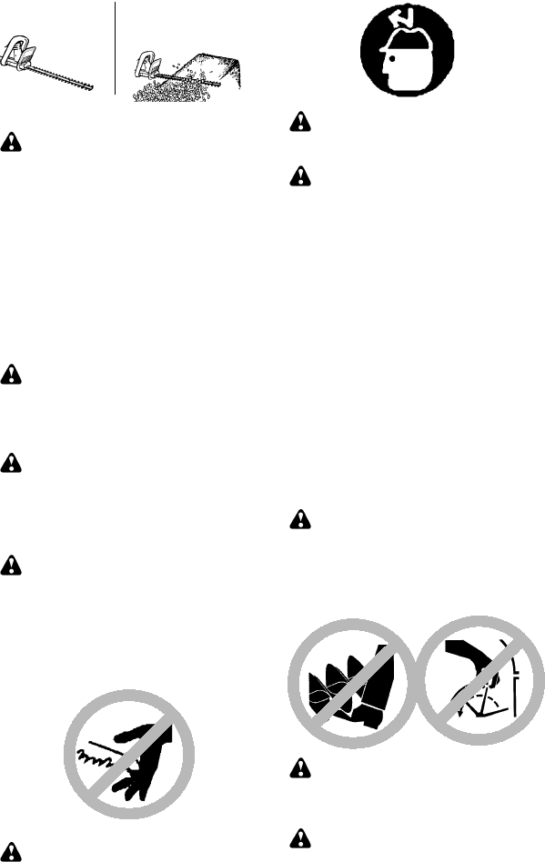
WARNING: Falling objects can
cause severe head injury. Wear head protec-
tion when operating this unit with a pole prun-
er attachment.
WARNING: To prevent serious injury,
do not use more than one boom extension with
a pole pruner attachment.
WARNING: Keep the pruner away
from power lines or electrical wires.
SOnly use for pruning limbs or branches up
to 4 inches (10 cm) in diameter.
SDo not operate the unit faster than the
speed needed to prune. Do not run the unit
at high speed when not pruning.
SAlways stop the unit when work is delayed
or when walking from onecutting location to
another.
SIf you strike or become entangled with a
foreign object, stop the engine immediately
and check for damage. Have any damage
repaired by an authorized service dealer
before attempting further operations.
Discard blades that are bent, warped,
cracked or broken.
SStop the unit immediately if you feel excessive
vibration. Vibration is a sign of trouble. Inspect
thoroughly for loose nuts, bolts or damage
before continuing. Contact an authorized
service dealer for repair or replacement of
affected parts as necessary.
SNOW THROWER SAFETY
WARNING: Keep hands and feet
away from the rotor when starting or running
the engine. Never attempt to clear the rotor
with the engine/motor running. Stop engine
and disconnect spark plug before unclogging
snow or debris from discharge chute or when
adjusting vanes.
WARNING: Never lean over dis-
charge chute. Rocks or debris could be
thrown into the eyes and face and cause seri-
ous injury or blindness.
WARNING: Inspect the area where
the unit is to be used. Remove objects that
could be thrown or damage the unit. Some
objects may be hidden by fallen snow -- be
alert for the possibility.
15
SDirect material discharge away from glass
enclosures, automobiles, etc.
SDo not run engine at high speed while not
removing snow.
SBe attentive when using the snowthrower,
and stay alert for holes in the terrain and other
hidden hazards.
SMake sure the rotor will spin freely before
attaching the snowthrower to the powerhead.
SIf therotor will not rotatefreely duetofrozen
ice, thaw the unit before thoroughly before
attempting to operate under power.
SKeep the rotor clear of debris.
SDo not throw snow near other people. The
snow thrower could propel small objects at
high speed causing injury.
SAfter striking a foreign object, stop the
engine, disconnect spark plug and inspect
the snowthrower for damage and repair if
necessary before restarting unit.
SNever operate the snowthrower near glass
enclosures, automobiles and trucks.
SNever attempt to use the snowthrower on a
roof.
SNever operate the snowthrower near
window wells, dropoffs, etc.
SNever discharge snow onto public roads or
near moving traffic.
SClear snow from slopes by going up and
down; never across. Use caution when
changing directions. Never clear snow
from steep slopes.
SLet snowthrowerrun for a few minutes after
clearing snow so moving parts do not
freeze.
SLook behind and use care when backing up.
Exercise caution to avoid slipping or falling,
especially when operating in reverse.
SKnow how to stop quickly.
MAINTENANCE
WARNING: Disconnect the spark
plug before performing maintenance except
for carburetor adjustments.
HELPFUL TIP
IMPORTANT: Have all
repairs other than the rec-
ommended maintenance
described in the instruction
manual performed by an
authorized service dealer.
If any dealer other than an authorized
service dealer performs work on the
product, Electrolux Home Products,
Inc., may not pay for repairs under war-
ranty. It is your responsibility tomaintain
and perform general maintenance.
CHECK FOR LOOSE
FASTENERS AND PARTS
SSpark Plug Boot
SAir Filter
SHousing Screws
SAssist Handle Screw
SDebris Shield
CHECK FOR DAMAGED OR
WORN PARTS
Contact an authorized service dealer for re-
placement of damaged or worn parts.
SON/OFF Switch -- Ensure ON/OFF switch
functions properly by moving the switch to
the OFF position. Make sure engine stops;
then restart engine and continue.
SFuel Tank -- Discontinue use of unit if fuel
tank shows signs of damage or leaks.
SDebris Shield -- Discontinue use of unit if
debris shield is damaged.
INSPECTAND CLEANUNIT ANDDE-
CALS
SAfter each use, inspect complete unit for
loose or damagedparts. Clean the unit and
decals using a dampcloth with a mild deter-
gent.
SWipe off unit with a clean dry cloth.
CLEAN AIR FILTER
A dirty air filter decreases engine perform-
ance and increases fuel consumption and
harmful emissions. Always clean after every
5 hours of operation.
1. Clean the cover and the area around it to
keep dirt from falling into the carburetor
chamber when the cover is removed.
2. Remove parts by pressing button to re-
lease air filter cover.
NOTE: To avoid creating a fire hazard or
producing harmful evaporative emissions, do
not clean filter in gasoline or other flammable
solvent.
3. Wash the filter in soap and water.
4. Allow filter to dry.
5. Replace parts.
Air Filter
Air Filter
Cover
Button
INSPECT MUFFLER AND SPARK
ARRESTING SCREEN
WARNING: The muffler on this prod-
uct contains chemicals known to the State of
California to cause cancer.
As your unit is used, carbon deposits build up
on the muffler and spark arresting screen and
must be removed to avoid creating a fire haz-
ard or affecting engine performance.
For normal homeowner use, the muffler and
spark arresting screen will not require any
service. After 50 hours of use, we recom-
mend that your muffler be serviced or re-
placed by an authorized service dealer.
16
REPLACE SPARK PLUG
Replace the spark plug each year to ensure
the engine starts easier and runs better. Set
spark plug gap at 0.025 inch (0.6 mm). Igni-
tion timing is fixed and nonadjustable.
1. Twist, then pull off spark plug boot.
2. Remove spark plug from cylinder and
discard.
3. Replace with Champion RCJ-6Y spark
plug and tighten securely with a 3/4 inch
(19 mm) socket wrench.
4. Reinstall the spark plug boot.
SERVICE AND ADJUSTMENTS
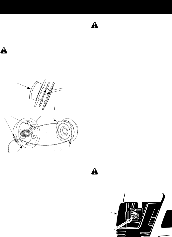
REPLACING THE LINE
1. Remove spool by firmly pulling on tap
button.
2. Clean entire surface of hub and spool.
3. Replace with a pre-wound spool, or cut two
lengths of 12-1/2 feet (3.8 meters) of 0.080!
(2 mm) diameter Poulan PROrbrand line.
WARNING: Never use wire, rope,
string, etc., which can break off and becomea
dangerous missile.
4. Insert ends of the lines about 1/2 inch (1
cm) into the small holes on the inside of
spool.
Small
Holes
Spool
Hub
Line in Notch
Line in Notch
Line exit holes
5. Wind the line evenly and tightly onto the
spool. Wind in the direction of the arrows
found on the spool.
6. Push the lines into the notches, leaving 3
to 5 inches (7 -- 12 cm) unwound.
7. Insert the lines into the the exit holes in
the hub as shown in the illustration.
8. Align the notches with the line exit holes.
9. Push spool into hub until it snaps into
place.
10. Pull the lines extending outside of thehub
to release the lines from the notches.
BLADE REPLACEMENT
Refer to the ASSEMBLY section for blade re-
placement instructions and illustrations.
CARBURETOR ADJUSTMENT
WARNING: Keep others away when
making idle speed adjustments. The trimmer
head, blade or any optional attachment will be
spinning during most of this procedure. Wear
your protective equipment and observe all safe-
ty precautions. After making adjustments, the
trimmer head, blade or any optional attachment
must not move/spin at idle speed.
The carburetor has been carefully set at the
factory. Adjustments may benecessary if you
notice any of the following conditions:
SEngine will not idle when the throttle is
released.
SThe trimmer head, blade or optional
attachment moves/spins at idle.
Make adjustments with the unit supported so
the cutting attachment is off the ground and
will not make contact with any object. Hold
the unit by hand while runningand making ad-
justments. Keep all parts of your body away
from the cutting attachment and muffler.
Idle Speed Adjustment
Allow engine to idle. Adjust speed until engine
runs without trimmer head, blade or optional
attachment moving or spinning (idle too fast)
or stalling (idle speed too slow).
STurn idle speed screw clockwise to
increase engine speed if engine stalls or
dies.
STurn idle speed screw counterclockwise to
decrease engine speed if trimmer head,
blade or optional attachment moves or
spins at idle.
WARNING: Recheck the idle speed
after each adjustment. The trimmer head,
blade or optional attachment must not move
or spin at idle speed to avoid serious injury to
the operator or others.
Idle Speed
Screw
Air Filter
Cover
If you require further assistance or areunsure
about performing this procedure, contact an
authorized service dealer or call
1--800--554--6723.

17
STORAGE
WARNING: Perform the following
steps after each use:
SAllow engine to cool before storing or trans-
porting.
SStore unit and fuel in a well ventilated area
where fuel vapors cannot reach sparks or
open flames from water heaters, electric
motors or switches, furnaces, etc.
SStore unit with all guards in place. Position
unit so that any sharp object cannot acci-
dentally cause injury.
SStore unit and fuel well out of the reach of
children.
SEASONAL STORAGE
Prepare unit for storageat end of season or if
it will not be used for 30 days or more.
If your unit is to be stored for a period of time:
SClean the entire unit before lengthy
storage.
SStore in a clean dry area.
SLightly oil external metal surfaces.
FUEL SYSTEM
Under FUELING ENGINE in the OPERA-
TION section of this manual,see message la-
beled IMPORTANT regarding the use of ga-
sohol in your engine.
Fuel stabilizer is an acceptable alternative in
minimizing the formation of fuel gum deposits
during storage. Add stabilizer to the gasoline
in the fuel tank or fuel storage container. Fol-
low the mix instructions found on stabilizer
container. Run engine at least 5 minutes after
adding stabilizer.
HELPFUL TIP
During storage of your gas/
oil mixture, the oil will sepa-
rate from the gas.
We recommend that you
shake the gas can weekly
to insure proper blending of
the gas and oil.
ENGINE
SRemove spark plugand pour 1 teaspoonof
40:1, 2-cycle engine oil (air cooled) through
the spark plug opening. Slowly pull the
starter rope 8 to 10 times to distribute oil.
SReplace spark plug with new one of recom-
mended type and heat range.
SClean air filter.
SCheck entire unit for loose screws, nuts,
and bolts. Replace any damaged, broken,
or worn parts.
SAt the beginning of the next season, use
only fresh fuel having the proper gasoline to
oil ratio.
OTHER
SDo not store gasoline from one season to
another.
SReplace your gasoline can if it starts to rust.

18
TROUBLE CAUSE REMEDY
Engine will not
start. 1.ON/OFF switch in
OFF position.
2. Engine flooded.
3. Fuel tank empty.
4. Spark plug not firing.
5. Fuel not reaching
carburetor.
6. Carburetor requires
adjustment.
1. Move ON/OFF switch to the ON
position.
2. See “Starting a Flooded Engine” in
Operation Section.
3. Fill tank with correct fuel mixture.
4. Install new spark plug.
5. Check for dirty fuel filter; replace.
Check for kinked or split fuel line;
repair or replace.
6. Contact an authorized service dealer.
Engine will
not idle
properly.
1. Carburetor requires
adjustment.
2. Crankshaft seals worn.
3. Compression low.
1. See “Carburetor Adjustment” in
Service and Adjustments Section.
2. Contact an authorized service dealer.
3. Contact an authorized service dealer.
1. Air filter dirty.
2. Spark plug fouled.
3. Carburetor requires
adjustment.
4. Carbon build-up on
muffler outlet screen.
5. Compression low.
Engine will not
accelerate,
lacks power,
or dies under
a load.
1. Clean or replace air filter.
2. Clean or replace plug
and regap.
3. Contact an authorized service dealer.
4. Contact an authorized service dealer.
5. Contact an authorized service dealer.
Engine
smokes
excessively.
1. Choke partially on.
2. Fuel mixture incorrect.
3. Air filter dirty.
4. Carburetor requires
adjustment.
1. Adjust choke.
2. Empty fuel tank and refill with
correct fuel mixture.
3. Clean or replace air filter.
4. Contact an authorized service dealer.
Engine runs
hot. 1. Fuel mixture incorrect.
2. Spark plug incorrect.
3. Carburetor requires
adjustment.
4. Carbon build-up on
muffler outlet screen.
1. See “Fueling Engine” in Operation
section.
2. Replace with correct spark plug.
3. Contact an authorized service dealer.
4. Contact an authorized service dealer.
WARNING: Always stop unit and disconnect spark plugbefore performingall of the
recommended remedies below except remedies that require operation of the unit.
TROUBLESHOOTING TABLE

19
LIMITED WARRANTY
ELECTROLUX HOME PRODUCTS, INC.,
warrants to the original purchaser that each
new Poulan PRO"
""
"brand gasoline tool or at-
tachment is free from defects in material and
workmanship and agrees to repair or replace
under this warranty any defective gasoline
product or attachment as follows from the
original date of purchase.
2 YEARS -- Parts and Labor, when used for
household purposes.
90 DAYS -- Parts and Labor, when used for
commercial, professional, or income produc-
ing purposes.
30 DAYS -- Parts and Labor, if used for rental
purposes.
This warrantyis not transferableand doesnot
cover damage or liability caused by improper
handling, improper maintenance, or the use
of accessories and/or attachments not spe-
cifically recommended by ELECTROLUX
HOME PRODUCTS,INC., for this tool. Addi-
tionally, this warranty does not cover tune-
ups, spark plugs, filters, cutting line, or rotat-
ing head parts that will wear and require
replacement with reasonable use during the
warranty period. This warranty does not cov-
er predelivery setup or normal adjustments
explained in the instruction manual.
THIS WARRANTY GIVES YOU SPECIFIC
LEGAL RIGHTS, AND YOU MAY HAVE
OTHER RIGHTS WHICH VARY FROM
STATE TO STATE.NO CLAIMS FOR CON-
SEQUENTIAL OROTHER DAMAGESWILL
BE ALLOWED, AND THERE ARE NO
OTHER EXPRESS WARRANTIES EX-
CEPT THOSE EXPRESSLY STIPULATED
HEREIN.
SOME STATES DO NOT ALLOW LIMITA-
TIONS ON HOW LONG AN IMPLIED WAR-
RANTY LASTS OR THE EXCLUSION OR
LIMITATIONS OF INCIDENTAL OR CON-
SEQUENTIAL DAMAGES, SO THE ABOVE
LIMITATIONS OR EXCLUSION MAY NOT
APPLY TO YOU.
The policy of ELECTROLUX HOME PROD-
UCTS, INC., is to continuously improve its
products. Therefore, ELECTROLUX HOME
PRODUCTS, INC., reserves the right to
change, modify, or discontinue models, de-
signs, specifications, and accessories of all
products at any time without notice or obliga-
tion to any purchaser.
U.S. EPA / CALIFORNIA / ENVIRONMENT CANADA
EMISSION CONTROL WARRANTY STATEMENT
YOUR WARRANTY RIGHTS AND OB-
LIGATIONS: The U.S. Environmental
Protection Agency/California Air Resources
Board,Environment CanadaandELECTRO-
LUX HOME PRODUCTS, INC., are pleased
to explain the emissions control system war-
ranty on your year 2002--2004 small off--road
engine. In California, all small off--road en-
gines must be designed, built, and equipped
to meet the State’s stringent anti--smog stan-
dards. ELECTROLUX HOME PRODUCTS,
INC., must warrant the emission control sys-
tem on your small off--road enginefor the peri-
ods of time listed below provided there has
been no abuse, neglect, or improper mainte-
nance of your small off--road engine. Your
emission control system includes parts such
as the carburetor and the ignition system.
Where a warrantablecondition exists, ELEC-
TROLUX HOME PRODUCTS, INC., will re-
pair your small off--road engine engine at no
cost to you. Expenses covered under warran-
ty include diagnosis, parts and labor.
MANUFACTURER’S WARRANTY COV-
ERAGE:If anyemissions relatedpart onyour
engine (as listed under Emissions Control
Warranty Parts List) is defective or a defect in
the materials or workmanship of the engine
causes the failure of such an emission related
part, the part will be repaired or replaced by
ELECTROLUX HOME PRODUCTS, INC.
OWNER’S WARRANTY RESPONSIBILI-
TIES: As the small off--road engine engine
owner, you are responsible for the perfor-
mance of the required maintenance listed in
your instruction manual. ELECTROLUX
HOME PRODUCTS,INC., recommends that
you retain all receipts covering maintenance
on your small off--road engine, but ELEC-
TROLUX HOME PRODUCTS, INC., cannot
deny warrantysolely for the lack of receipts or
for your failure to ensure the performance of
all scheduled maintenance. As the small off--
road engine engine owner, you should be
aware that ELECTROLUX HOME PROD-
UCTS, INC., may deny you warranty cover-
age if your small off--road engine engine or a
part of it has failed due to abuse, neglect, im-
proper maintenance, unapproved modifica-
tions, or the use of parts not made or ap-
proved by the original equipment
manufacturer. You are responsible for pres-
enting your small off--road engine to an
ELECTROLUX HOME PRODUCTS, INC.,
authorizedrepaircenter assoonas aproblem
exists. Warranty repairs should be completed
in a reasonable amountof time, not to exceed
30 days. If you have any questions regarding
your warranty rights and responsibilities, you
should contact your nearest authorized ser-
vice center or call ELECTROLUX HOME
PRODUCTS, INC., at 1--800--554--6723.
WARRANTY COMMENCEMENT DATE:
The warranty period begins on the date the
small off--road engine is purchased.
LENGTH OF COVERAGE: This warranty

20
shall be for a period of two years from the ini-
tial date of purchase. WHAT IS COVERED:
REPAIR OR REPLACEMENT OF PARTS.
Repair or replacement of any warranted part
will be performedat no charge to the owner at
an approved ELECTROLUX HOME PROD-
UCTS, INC., servicing center. If you haveany
questions regarding your warranty rights and
responsibilities, you should contact your
nearest authorized service center or call
ELECTROLUXHOMEPRODUCTS,INC.,at
1--800--554--6723. WARRANTY PERIOD:
Any warrantedpart which is not scheduledfor
replacement as required maintenance, or
which is scheduled only for regular inspection
to the effect of “repair or replace as neces-
sary” shall be warrantedfor 2 years. Any war-
ranted part which is scheduled for replace-
ment as required maintenance shall be
warrantedfor the period of time up to the first
scheduled replacement point for that part.
DIAGNOSIS: The owner shall not be
charged for diagnostic labor which leads to
the determination that a warrantedpart is de-
fective if the diagnostic work is performed at
an approved ELECTROLUX HOME PROD-
UCTS, INC., servicing center. CONSE-
QUENTIAL DAMAGES: ELECTROLUX
HOME PRODUCTS, INC., may be liable for
damages to other engine components
caused by the failure of a warranted part still
under warranty. WHAT IS NOT COVERED:
All failures caused by abuse, neglect, or im-
proper maintenance are not covered. ADD--
ON OR MODIFIED PARTS: The use of add--
on or modified parts can be grounds for
disallowing a warranty claim. ELECTROLUX
HOME PRODUCTS, INC., is not liable to
cover failures of warranted parts caused by
the use of add--on or modified parts. HOW TO
FILE A CLAIM: If you have any questions re-
garding your warrantyrights andresponsibili-
ties, you should contact your nearest autho-
rized service center or call ELECTROLUX
HOME PRODUCTS, INC., at
1--800--554--6723. WHERE TO GET WAR-
RANTY SERVICE: Warranty services or re-
pairs shall be provided at all ELECTROLUX
HOME PRODUCTS, INC., service centers.
Call: 1--800--554--6723 MAINTENANCE,
REPLACEMENT AND REPAIR OF EMIS-
SION RELATED PARTS: Any ELECTRO-
LUX HOME PRODUCTS, INC., approvedre-
placement part used in the performance of
any warranty maintenance or repair on emis-
sion related parts will be provided without
charge to the owner if the part is under war-
ranty. EMISSION CONTROL WARRANTY
PARTS LIST: Carburetor, Ignition System:
Spark Plug (covered up to maintenance
schedule), Ignition Module, Muffler including
catalyst. MAINTENANCE STATEMENT:
The owner is responsible for the performance
of all required maintenance as defined in the
instruction manual.
The information on the product label indicates which standard your engine is certified.
Example: (Year) EPA Phase 1 or Phase 2 and/or CALIFORNIA.
This engine is certified to be emissions compliant for the following use:
Moderate (50 hours)
Intermediate (125 hours)
Extended (300 hours)
