Poulan RT112C 545117537e User Manual To The 56bed657 13ad 4194 85f3 2c4890bcfd6d
User Manual: Poulan RT112C to the manual
Open the PDF directly: View PDF ![]() .
.
Page Count: 9
RT112C
RTrademark
Instruction Manual
Manual de Instrucciones
Manuel d’Instructions
ENGLISH ESPAÑOL FRANÇAIS
545117537 8/8/06
Please do not return unit to retailer.
Por favor, no devuelva el aparato al lugar de compra.
Veuillez ne pas retourner l’outil au détaillant.
1-800-554-6723
www.weedeater.com
WEED EATER
1030 Stevens Creek Road
Augusta, GA 30907
WEED EATER
5855 Terry Fox Way
Mississauga, Ontario L5V 3E4
WARNING:
Read and follow all Safety Rules and Operating Instructions before
using this product. Read instructions carefully before assembling.
Failure to do so can result in serious injury.
ADVERTENCIA:
Lea el manual del operador y siga todas las advertencias e instruc-
ciones de seguridad. Antes de ensamblar el producto lea cuidado-
samente el instructivo. El no hacerlo puede resultar en lesiones gra-
ves.
AVERTISSEMENT:
Veuillez lire le manuel de l’utilisateur et bien respecter tous les
avertissements et toutes les instructions de sécurité. Bien lire les
instructions avant d’assembler l’outil. Tout défaut de le faire pourrait
entraîner des blessures graves.
2
SAFETY RULES
WARNING: When using electric gar-
dening appliances, basic safety precautions
must always be followed to reduce the risk of
fire, electric shock, and serious injury. Read
and follow all instructions.
SAFETY INFORMATION
ON THE UNIT
This power unit can be dangerous! Operator
is responsible for following the warnings and
instructions in this manual and on the unit.
Read entire instruction manual before using
unit! Be thoroughly familiar with the controls
and the proper use of the unit. Restrict the use
of this unit to persons who read, understand,
and follow unit and manual warnings and
instructions. Never allow children to operate
this unit. Close attention is necessary when
used near children.
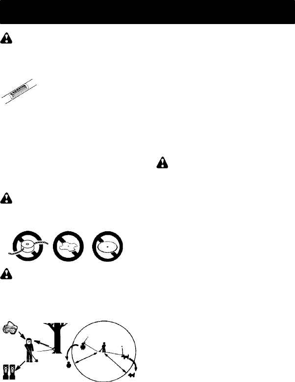
DANGER: Never use blades or flail-
ing devices. Unit is designed for line trimmer
use only. Use of any other accessories or at-
tachments will increase the risk of injury.
WARNING: Trimmer line throws ob-
jects violently. You and others can be blinded/
injured. Wear safety glasses, boots, and leg
protection. Keep body parts clear of rotating
line.
Safety Glasses or similar eye protection
Boots
Hazard Zone
15 m
50 ft.
Keep children, bystanders, and animals 50
feet (15 meters) away. If approached stop unit
immediately.
If situations occur which are not covered in
this manual, use care and good judgement. If
you need assistance, call 1-800-554-6723.
OPERATOR SAFETY
SDress properly. Always wear safety
glasses or similar eye protection when op-
erating, or performing maintenance on your
unit. (Safety glasses are available.) Always
wear face or dust mask if operation is dusty.
Always wear heavy, long pants, long
sleeves, boots, and gloves. Do not go bare-
foot or wear sandals.
SSecure hair above shoulder length. Secure
or remove loose clothing and jewelry or
clothing with loosely hanging ties, straps,
tassels, etc. They can be caught in moving
parts.
SBeing fully covered also helps protect you
from debris and pieces of toxic plants
thrown by spinning line.
SStay Alert.Do not operate unit when you
are tired, ill, upset or under influence of al-
cohol, drugs, or medication. Watch what
you are doing; use common sense.
SAvoid unintentional starting of the unit.
Never carry unit with your finger on the
switch. Be sure the switch is in the OFF
position and never touch the switch when
connecting extension cord.
ELECTRICAL SAFETY
WARNING: Avoid a dangerous envi-
ronment. To reduce the risk of electrical
shock, do not use in rain, in damp or wet loca-
tions, or around swimming pools, hot tubs,
etc. Do not expose to snow, rain, or water to
avoid the possibility of electrical shock.
SUse a voltage supply as shown on unit.
SAvoid dangerous situations. Do not use in
the presence of flammable liquids or gases
to avoid creating a fire or explosion and/or
causing damage to unit.
STo reduce the risk of electrical shock, this
equipment has a polarized plug (one blade
is wider than the other) and will require the
use of a polarized extension cord. The ap-
pliance plug will fit into a polarized exten-
sion cord only one way. If the plug does not
fit fully into the extension cord, reverse the
plug. If the plug still does not fit, obtain a
correct polarized extension cord. A polar-
ized extension cord will require the use of a
polarized wall outlet. This plug will fit into
the polarized wall outlet only one way. If
plug does not fit fully into the wall outlet, re-
verse the plug. If it still does not fit, contact a
qualified electrician to install the proper wall
outlet. Do not change the equipment plug,
extension cord receptacle, or extension
cord plug in any way.
STo reduce risk of electrical shock, use ex-
tension cords specifically marked as suit-
able for outdoor appliances having electri-
cal rating not less than the rating of unit.
Cord must be marked with suffix “W--A” (in
Canada “W”). Make sure your extension
cord is in good condition. Inspect extension
cord before use and replace if damaged. Do
not use a damaged cord. Cord insulation
must be intact with no cracks or deteriora-
tion. Plug connectors must be undamaged.
An undersized extension cord will cause a
drop in line voltage resulting in loss of pow-
er and overheating. If in doubt, use the next
heavier gauge. The lower the gauge num-
ber, the heavier the cord (see SELECT AN
EXTENSION CORD in the OPERATION
section).
SDo not use multiple cords.

3
SDo not abuse cord. Never carry the unit by
the extension cord or yank extension cord
to disconnect unit.
SUse cord retainer to prevent disconnection
of extension cord from unit and possible
damage to the unit due to plug movement
(see ATTACH THE EXTENSION CORD
TO YOUR TRIMMER in the OPERATION
section).
SDo not use the unit if the switch does not
turn the unit on and off properly. Repairs to
the switch must be made by your autho-
rized service dealer.
SKeep the extension cord clear of operator
and obstacles at all times. Do not expose
cords to heat, oil, water, or sharp edges.
STo avoid the possibility of electric shock,
avoid body contact with any grounded con-
ductor, such as metal fences or pipes.
SGround Fault Circuit Interrupter (GFCI)
protection should be provided on circuit or
outlet to be used. Receptacles are avail-
able having built-in GFCI protection and
may be used for this measure of safety.
UNIT SAFETY
SInspect unit before use. Replace damaged
parts. Make sure all handles, guards, and
fasteners are in place and securely fas-
tened. Parts that are damaged must be re-
paired or replaced by an authorized service
dealer These include head parts that are
cracked, or chipped, guards, and any other
part that is damaged.
SDo not repair unit yourself.
SUse only 0.065 inch (1.65 mm) diameter
recommended trimmer line (see USER RE-
PLACEABLE SERVICE PARTS in the
SERVICE AND ADJUSTMENTS section).
Never use wire, rope, string, etc.
SUse specified trimmer spool. Make sure
spool is properly installed and all parts are
securely fastened.
SUse only WEED EATER replacement parts
and accessories as recommended.
CUTTING SAFETY
WARNING: Inspect area to be cut.
Remove objects (rocks, broken glass, nails,
wire, string, etc.) which can be thrown or be-
come entangled in cutting head.
SDo not overreach or stand on unstable sup-
port. Keep firm footing and balance.
SKeep the cutting head below waist level. Do
not raise handles above your waist. Cutting
head can come dangerously close to your
body.
SKeep away from cutting head and spinning
line.
SUse unit properly. Use only for trimming,
scalping, and mowing. Do not force unit. It
will do the job better and with less risk of in-
jury at the rate for which it was designed.
SUse only in daylight or in good artificial light.
MAINTENANCE SAFETY
WARNING: Disconnect unit from the
power supply before performing mainte-
nance, or when changing trimmer line.
SMaintain unit according to recommended
procedures. Keep cutting line at proper
length. Follow instructions for changing
trimmer line.
SHave all service and maintenance not ex-
plained in this manual performed by an au-
thorized service dealer to avoid creating a
hazard.
SNever douse or squirt the unit with water or
any other liquid. Clean unit and labels with
a damp sponge. Keep handles dry, clean,
and free from oil and grease.
SKeep the air vents clean and free of debris
to avoid overheating the motor. Clean after
each use.
TRANSPORTING AND STORAGE
SStop the unit and disconnect the power
source when not in use.
SCarry the unit with motor stopped.
SStore the unit so the line limiter blade (on
underside of shield) cannot cause injury.
SStore unit indoors in a high, dry place out of
the reach of children. Store unit unplugged.
SDo not hang unit so that the trigger switch is
depressed.
DOUBLE INSULATION
CONSTRUCTION
This unit is double insulated to help protect
against electric shock. Double insulation
construction consists of two separate “layers”
of electrical insulation instead of grounding.
Tools built with this insulation system are not
intended to be grounded. No grounding
means is provided on this unit, nor should a
means of grounding be added to this unit. As a
result, the extension cord used with your unit
can be plugged into any standard 120 volt
electrical outlet.
Safety precautions must be observed when
operating any electrical tool. The double in-
sulation system only provides added protec-
tion against injury resulting from an internal
electrical insulation failure.
WARNING: All electrical repairs to
this unit, including housing, switch, motor,
locking sleeve assembly, wires, etc., must be
diagnosed and repaired by qualified service
personnel. Replacement parts for a double in-
sulated appliance must be recommended by
the manufacturer. A double insulated ap-
pliance is marked with the words “double in-
sulation” or “double insulated”. The symbol
(square within a square) may also be
marked on the appliance. Failure to have the
unit repaired by qualified service personnel
can cause the double insulation construction
to become ineffective and result in serious
injury.
SAVE THESE INSTRUCTIONS
4
ASSEMBLY
WARNING: If received assembled,
review all assembly steps to ensure your unit
is properly assembled and all fasteners are
secure.
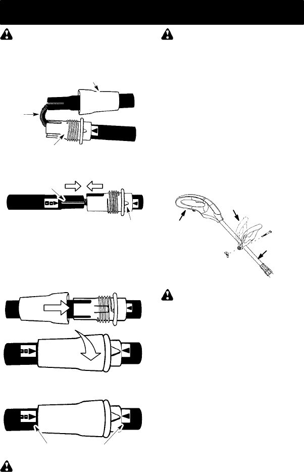
TUBE ASSEMBLY
Wires
Upper Locking Sleeve Assembly
Lower Locking Sleeve Assembly
1. Align upper tube groove with triangle on
lower locking sleeve assembly. Push
tubes together until they snap into place.
Alignment Triangle
Upper Tube
Groove
2. Try to pull tubes back apart. If the tubes do
not come apart, they are properly snapped
into place. If the tubes come apart, repeat
step 1 and push until the tubes snap into
place.
3. Slide upper locking sleeve assembly over
lower locking sleeve assembly and tight-
en by turning clockwise.
4. Ensure locking sleeve assembly and
alignment decals appear as illustrated be-
low.
Alignment decals
WARNING: Failure to completely en-
close excess wires in upper tube during assem-
bly of the unit may result in damage to the wires
and/or the unit or serious injury to the operator
including electrocution.
WARNING: The upper and lower
tubes must be snapped together, remain per-
manently assembled together and the locking
sleeve assembly must be fully tightened be-
fore and during use to avoid serious injury to
the operator and/or damage to the unit. DO
NOT attempt to disassemble unit after initial
assembly.
INSTALLATION OF ASSIST HANDLE
1. Loosen and remove wing nut and bolt
from assist handle.
2. Place unit on a flat surface.
3. Firmly push the assist handle over the
tube. To make installation easier, tilt han-
dle toward trigger housing while pushing
down (see illustration).
4. Reinstall bolt in handle. Thread wing nut
onto bolt.
5. Adjust the handle up or down the tube to a
comfortable position; tighten wing nut se-
curely.
Assist handle
Trigger
housing
Tube
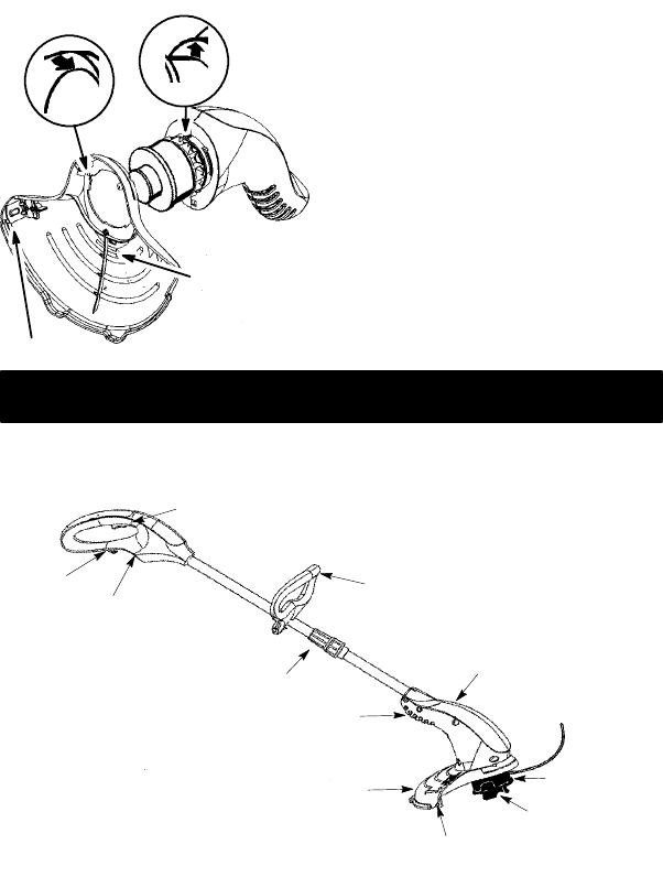
ATTACHING THE SHIELD
WARNING: The shield must be prop-
erly installed. The shield provides partial
protection from the risk of thrown objects to
the operator and others. Your unit is equipped
with a line limiter blade, which cuts excess
line to the proper length while running. The
line limiter blade (on underside of shield) is
sharp and can cut you.
NOTE: If shield is not properly installed, dam-
age to unit (including motor failure) will result.
1. Align the installation arrow on the shield
with the installation arrow on the motor
housing (see illustration below).
2. Insert the shield onto the motor housing.
Ensure the cutting head remains free to
rotate and the line is not caught between
the shield and the motor housing.
3. Twist the shield as illustrated until it snaps
securely into place. Make sure the shield
is assembled to the unit as shown in the
illustration below and in the KNOW
YOUR UNIT section of this manual.
5
CAUTION: Sharp line limiter blade
ALIGN INSTALLATION ARROWS
Twist shield
in direction of
arrow to
assemble
OPERATION
KNOW YOUR TRIMMER
READ THIS INSTRUCTION MANUAL AND SAFETY RULES BEFORE OPERATING YOUR UNIT.
Compare the illustrations with your unit to familiarize yourself with the location of the various controls
and adjustments. Save this manual for future reference.
Recessed
Plug
Trigger Switch
Cord
Retainer
Air
Vents
Debris Shield
Line Limiter Blade
Motor Housing
Trimmer Head
with 0.065 in.
Trimmer Line
Assist Handle
Ta p B u t t o n
Locking
Sleeve
Assembly
RECESSED PLUG
The RECESSED PLUG is where you attach
your extension cord to the unit.
TRIGGER SWITCH
TheTRIGGERSWITCHisusedtoturnonthe
unit. Squeeze the trigger switch to operate the
unit. Release to stop.
LINE LIMITER BLADE
The LINE LIMITER BLADE cuts the cutting
line to the proper cutting length.
ASSIST HANDLE
The ASSIST HANDLE is used to help hold
and guide the unit.
TRIMMER HEAD
The TRIMMER HEAD holds cutting line and
rotates during operation.
TAP BUTTON
The TAP BUTTON is used to advance the
cutting line during operation and to remove
the spool during line replacement.
6
OPERATING INSTRUCTIONS
Use only a voltage supply as specified on
your unit.
SELECT AN EXTENSION CORD
Extension Cord Gauge Chart
Length of Cord Gauge
25 Ft. (7.5 m)
50 Ft. (15 m)
100 Ft. (30 m)
18 Gauge
16 Gauge
16 Gauge
Extension cords are available for this unit.
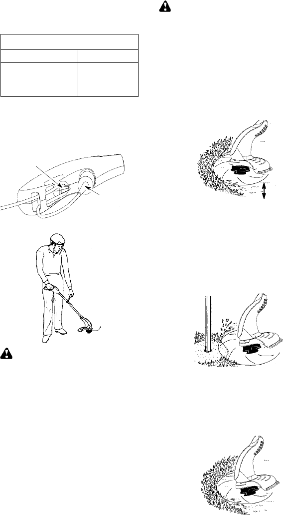
ATTACH THE EXTENSION
CORD TO YOUR TRIMMER
Loop your extension cord through the handle
and around the hook as shown. Insure the
plug and cord are firmly and fully engaged.
Cord Retainer
Extension Cord
CORRECT OPERATING POSITION
Trimming
WARNING: Always wear eye protec-
tion. Never lean over the trimmer head.
Rocks or debris can ricochet or be thrown into
eyes and face and cause blindness or other
serious injury.
When operating unit, stand as shown and
check for the following:
SWear eye protection and heavy clothing.
SHold trigger handle with right hand and as-
sist handle with left hand.
SKeep unit below waist level.
SCut only from your right to your left to en-
sure debris is thrown away from you. With-
out bending over, keep line near and paral-
lel to the ground and not crowded into
material being cut.
ADVANCING THE CUTTING LINE
Advance line by tapping bottom of cutting
head lightly on the ground while unit is running
at full speed. A metal line limiter blade at-
tached to the shield will cut the line to the
proper length.
WARNING: Use only 0.065 inch (1.65
mm) diameter line. Other sizes of line will not ad-
vance properly and will result in improper cutting
head function or can cause serious injury. Do
not use other materials such as wire, string,
rope, etc. Wire can break off during cutting and
become a dangerous missile that can cause se-
rious injury. See page 2 for warning concerning
other cutting devices.
TRIMMING
Hold the bottom of the trimmer head about 3
inches (8 cm) above the ground and at an an-
gle. Allow only the tip of the line to make con-
tact. Do not force trimmer line into work area.
Trimming
3 in. (8 cm)
Above Ground
SCALPING
The scalping technique removes unwanted
vegetation down to the ground. Hold the bot-
tom of the trimmer head about 3 inches (8 cm)
above the ground and at an angle. Allow the
tip of the line to strike the ground around trees,
posts, monuments, etc. This technique in-
creases line wear.
Scalping
MOWING
Your trimmer is ideal for mowing in places
conventional lawn mowers cannot reach. In
the mowing position, keep the line parallel to
the ground. Avoid pressing the head into the
ground as this can scalp the ground and dam-
age the tool.
Mowing
7
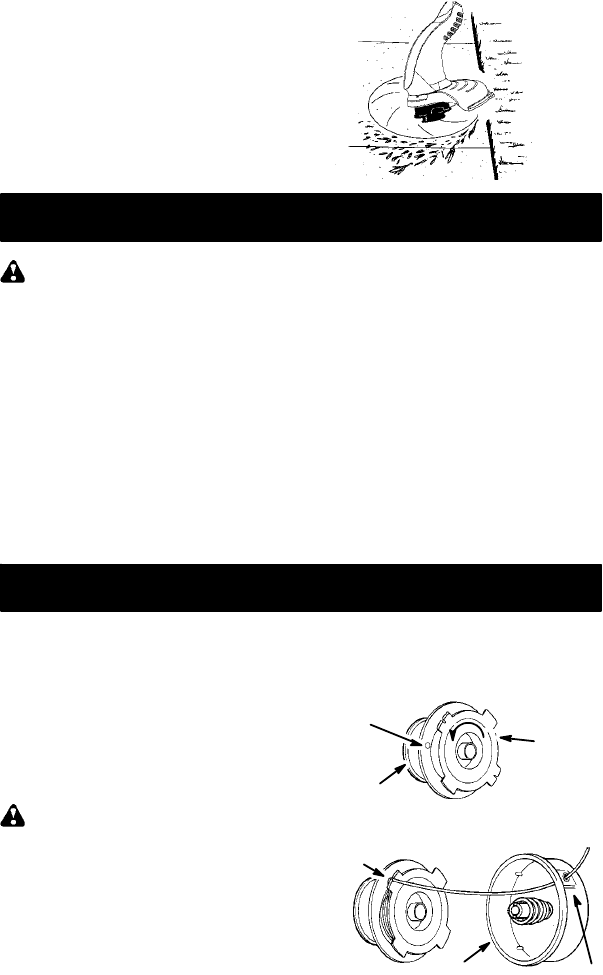
SWEEPING
The fanning action of the rotating line can be
used for a quick and easy clean up. Keep the
line parallel to and above the surfaces being
swept and move the tool from side to side.
Sweeping
MAINTENANCE
WARNING: Disconnect unit from the
power source before performing mainte-
nance.
GENERALRECOMMENDATIONS
The warranty on this unit does not cover items
that have been subjected to operator abuse
or negligence. To receive full value from the
warranty, the operator must maintain unit as
instructed in this manual. Various adjust-
ments will need to be made periodically to
properly maintain your unit.
BEFORE EACH USE
CHECK FOR LOOSE
FASTENERS AND PARTS
SHousing Screws
SLocking Sleeve Assembly
SAssist Handle
SDebris Shield
CHECK FOR DAMAGED OR
WORN PARTS
Contact an authorized service dealer for re-
placement of damaged or worn parts.
STrigger Switch -- Ensure switch functions
properly by pressing and releasing the trig-
ger switch. Make sure motor stops.
SDebris Shield -- Discontinue use of unit if
debris shield is damaged.
AFTER EACH USE
INSPECT AND CLEAN UNIT AND LA-
BELS
SAfter each use, inspect complete unit for
loose or damaged parts. Clean the unit us-
ing a damp cloth with a mild detergent.
SWipe off unit with a clean dry cloth.
SERVICE AND ADJUSTMENTS
REPLACING THE LINE
1. Disconnect the unit from the power
source.
2. Remove the spool by firmly pulling on the
tap button.
3. Clean entire surface of hub and spool.
4. Replace with a pre-wound spool or cut a
length of 30 feet of 0.065″(1.65 mm) di-
ameter WEED EATER brand line. Use of
heavier lines could overload and damage
unit.
WARNING: Never use wire, rope,
string, etc., which can break off and become a
dangerous missile.
5. Insert one end of the line about 1/2 inch (1
cm) into the small hole inside the spool.
6. Wind the line evenly and tightly onto the
spool. Wind in the direction of the arrow
found on the spool.
7. Push the line into the notch, leaving 3 to 5
inches (7 -- 12 cm) unwound.
8. Insert the line into the exit hole in the hub
as shown in the illustration.
9. Align the notch with the line exit hole.
10. Push the spool into the hub until it snaps
into place.
11. Pull on the line extending outside the hub
to release it from the notch; otherwise, the
unit will not function properly.
Small
Hole
Spool
Tap
Button
Hub Line exit hole
L
ine in Notch

8
USER REPLACEABLE SERVICE PARTS
Spool with 0.065″Trimmer Line 952701663
Assist Handle 530403805
Bolt Carriage, 1/4-20 530403886
Wing Nut 530016152
Shield Assembly 530404076
REPLACEMENT PART PART NUMBER
STORAGE
WARNING: Perform the following
steps after each use.
SStop the unit and disconnect the power
source when not in use.
SCarry the unit with motor stopped.
SStore the unit so the line limiter blade can-
not cause injury.
SStore unit and extension cord indoors in a
high, dry place out of the reach of children.
Store unit unplugged.
SStore unit with all guards in place. Position
unit so that any sharp object cannot acci-
dentally cause injury.
TROUBLE CAUSE REMEDY
Trimmer head
stops under a
load or does not
turn when switch
is pressed.
1. Allow tip of line to do the cutting.
2. Contact your authorized service dealer.
3. Check Breaker Box.
4. Remove debris.
Line does not
advance or
breaks while
cutting.
1. Check line routing.
2. Rewind line tightly and evenly.
3. Use only 0.065 in. (1.65 mm) dia. line.
4. Remove cover and pull 4 inches
(10 cm) of line out of head.
5. Clean unit.
Line welds onto
spool.
1. Use only 0.065 in. (1.65 mm) dia. line.
2. Replace with correct spool.
3. Cut with tip of line fully extended.
Line releases
continuously. 1. Check line routing.
2. Replace spool.
Line pulls back
into head.
1. Too little line outside
of head.
2. Line size incorrect.
1. Remove cover and pull 4 inches
(10 cm) of line outside of head.
2. Use only 0.065 in. (1.65 mm) dia. line.
TROUBLESHOOTING TABLE
1. Line improperly
routed in head.
2. Spool damaged.
1. Line size is incorrect.
2. Incorrect spool.
3. Line is being crowded
against material being
cut.
1. Line improperly routed
in head.
2. Line improperly
wound into spool.
3. Incorrect line size
4. Not enough line
outside of head.
5. Dirt buildup on unit.
1. Crowding trimmer line
against material being
cut.
2. Electrical failure.
3. Thrown circuit breaker.
4. Debris stopping head.
Line usage is
excessive. 1. Check line routing.
2. Replace spool.
3. Cut with tip of line fully extended.
4. Replace spool.
1. Line improperly routed
in head.
2. Line size is incorrect.
3. Crowding line against
material being cut.
4. Spool worn or damaged.
WARNING: Always stop unit and disconnect from the power source before performing
all of the recommended remedies below except remedies that require unit to be operating.

9
LIMITED WARRANTY
WEED EATER warrants to the original pur-
chaser that each new WEED EATER brand
electric or cordless product is free from de-
fects in material and workmanship and
agrees to repair or replace under this war-
ranty any defective WEED EATER brand
electric product within two (2) years from the
original date of purchase.
If your WEED EATER brand electric or cord-
less product should fail within the limited
warranty period, return it, complete, prepaid,
with proof of purchase, to the dealer from
whom it was purchased for repair or replace-
ment at the option of WEED EATER.
This warranty is not transferable and does not
cover damage or liability caused by improper
handling, improper maintenance or the use of
accessories and/or attachments not specifically
recommended by WEED EATER for this elec-
tric product. Additionally, this warranty does not
cover parts that will wear and require replace-
ment with reasonable use during the warranty
period. This warranty does not cover predeliv-
ery set--up or normal adjustments explained in
the instruction manual.
THIS WARRANTY GIVES YOU SPECIFIC
LEGAL RIGHTS, AND YOU MAY HAVE
OTHER RIGHTS WHICH VARY FROM
STATE TO STATE.
NO CLAIMS FOR CONSEQUENTIAL OR
OTHER DAMAGES WILL BE ALLOWED,
AND THERE ARE NO OTHER EXPRESS
WARRANTIES EXCEPT THOSE EX-
PRESSLY STIPULATED HEREIN.
SOME STATES DO NOT ALLOW LIMITA-
TIONS ON HOW LONG AN IMPLIED WAR-
RANTY LASTS OR THE EXCLUSION OR
LIMITATIONS OF INCIDENTAL OR CON-
SEQUENTIAL DAMAGES, SO THE ABOVE
LIMITATIONS OR EXCLUSION MAY NOT
APPLY TO YOU.
The policy of WEED EATER is to continu-
ously improve its products. Therefore, WEED
EATER reserves the right to change, modify,
or discontinue models, designs, specifica-
tions, and accessories of all products at any
time without notice or obligation to any pur-
chaser.
