Power 7 Technology WFOUTLET Wifi Outlet User Manual
Power7 Technology(Dong Guan) Co., Ltd. Wifi Outlet
User Manual
1
WiFi Outlet
Version 0.2
Last Updated: 2015.9.17

2
CONTENTS
1 Product introduction ....................................................................................................................... 3
2 Product specification ...................................................................................................................... 4
3 Software Parameters ...................................................................................................................... 6
4 Application scenarios ...................................................................................................................... 6
5. Client Tools .................................................................................................................................... 8
5.1 Login device ......................................................................................................................... 8
5.2 Outlet Catalog .................................................................................................................... 11
5.3 Scene page ........................................................................................................................ 17
5.4 Remote access .................................................................................................................. 18
6. FCC Statement ............................................................................................................................ 19
3
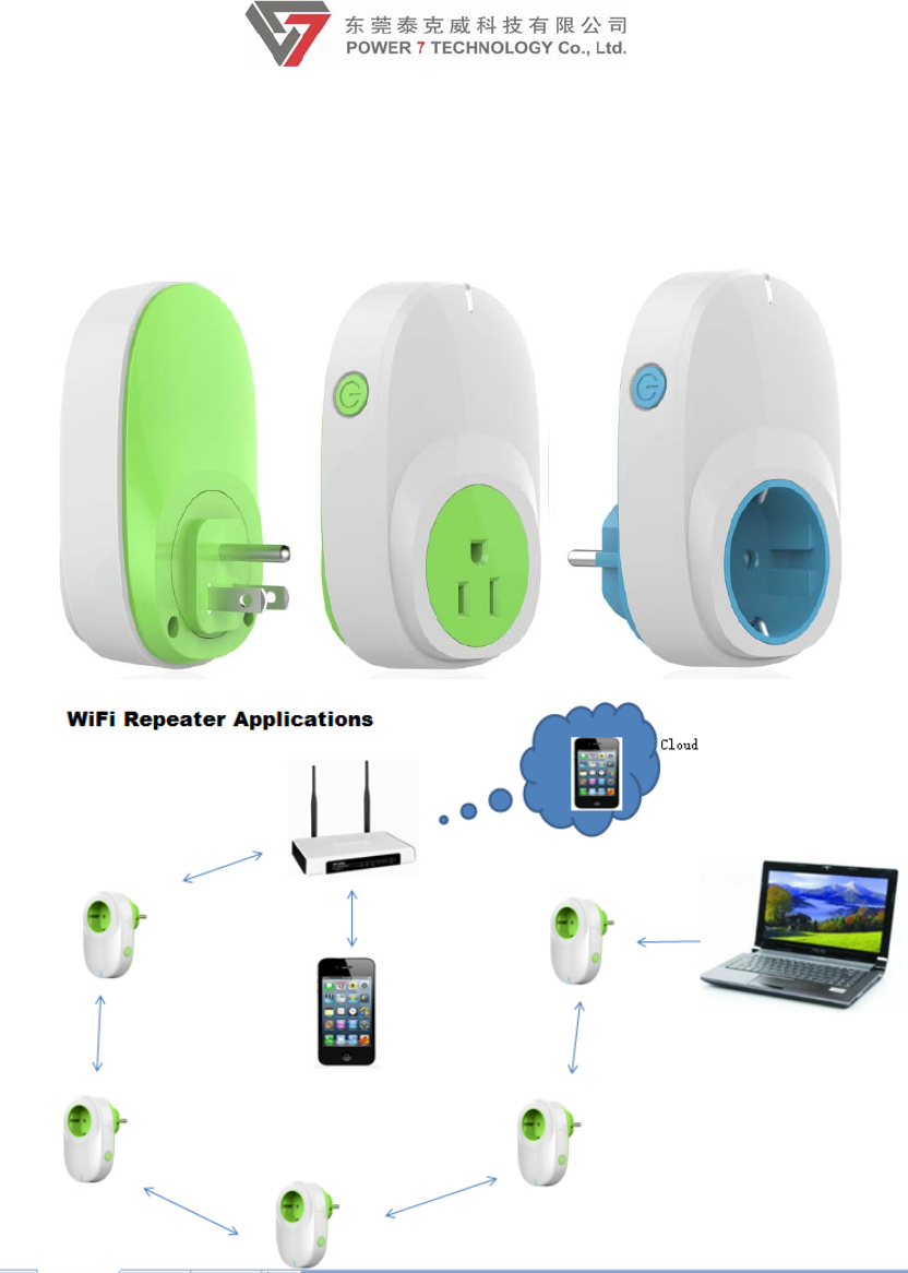
1 Product introduction
This is a kind of smart Outlet by using Internet of Things technologies (IOT). The
smart Outlet is connected to the mobile phone with Wi-Fi, and then the mobile phone
can control the smart Outlet. The smart Outlet can be directly connected to the mobile
phone or Tablet PC with WI-FI, and it also can make the remote control comes true
through the router. When you install APP in your mobile phone and the electrical
equipment is connected to the smart Outlet, you can control the power switches by
using your mobile phone. The smart Outlet is used as the signal relaying device
beyond the coverage of your own home wireless network. And it can be connected
to each other among the smart Outlets. It can turn off all of the powers of electric
equipment which are connected to the smart Outlets with APP.
It is the simple way to make your Household equipment become smart. And you can
control Household equipment and light by using the smart Outlet. It is so easy to use.
And it provides a smart plan to make your life more smart, comfortable, safety.
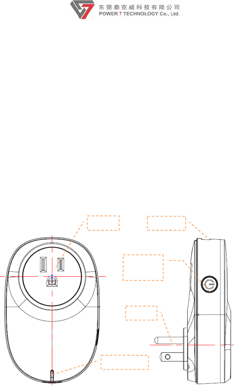
Picture describe:
1.Outlet: Connect electric consuming equipment, supply power for these equi
pment
2.USB Port:Can charge the phone and connect intelligent controled plug-in, eg. USB
vidicon, temperature and humidity sensor, infrared sensor and so on. but the ADT
need extra charge, for detail information please contact POWER7 or access the
1.Outlet
5.LED Light
4.Plug
2.USB Port
3.Function
button

4
web:www.power7tech.com
3.Function Button:Used to control and Wi-Fi connection mode switch ,1~5s and the
blue light quick flashing is Smart connection model, 5~10s and the blue light slow
flashing is system reset model ,press the button until the blue light slow flashing and
stop press is reset to factory pattern.
4.Plug:Connect Outlet, supply power for smart outlet
5.LED light:Green light bright the switch is on, green light dark stands switch off.
Blue light long bright Wi-Fi dis-connection, blue light dark stands Wi-Fi connected.
Blue light slow shining go into system reset model, blue light quick shining go into
Smart connection model.
2 Product specification
2.1HardwareParameters
◆CPU MTK7688A
◆Power supply mode: AC 110-240V 50Hz/60Hz
◆The maximum power : 3840W(Resistive load)
◆The maximum load current: 16A
◆PLUG standard: EU CEE7/7,US NEMA 5-15P
◆Outlet standard: EU CEE7/7,US NEMA 5-15P
◆Wireless standard: Wi-Fi 2.4GHz 802.11b/g/n
◆The distance between sending and receiving is about 30m (straight line distance)
◆Boot times < 10 seconds, first use < 1 minute
◆Standby Power Consumption:≦2W
◆Connection power consumption :≦2W
◆Working temperature : 5~40℃

5
◆Working humidity: ≦80%
2.2FunctionOverview
◆Support Wi-Fi 2.4GHz 802.11b g/n, customizable support the Zigbee Protocol.
◆Support the Smart connection technology and the Apple’s HomeKit Accessory
Protocol.(Optional,Temporarily not supporting this feature)
◆Support cellphone connections and the connections through wireless routers, mobile
phone remote control via Wi-Fi/2G/3G/4G mobile network.
◆Control smart Outlets via phone and Tablet, and support set the timer switch.
◆Support electrical energy measurement, could know use quantity of electricity
through APP.
◆Support overloads protection function, when the electrical equipment which is
connected to the smart Outlet is out of the rated power range, the smart Outlet will
power off automatically.
◆Plug and play. Use and connections are simple. When smart Outlet power on, it can
be connected to the router automatically. Through the app, you only one step to
complete setting. You don’t need to set the IP address. After the first setting
successfully, you don’t need to set again, unless the router setting is to change.
◆Support Wi-Fi signal relay. The signal is strengthened beyond the coverage of Wi-Fi
signal. Multiple smart Outlets can be connected to each other. All of the powers of the
smart Outlets can be turned off by APP.
◆Support scenario settings. According to the different rooms or connective device’s
types, the smart Outlet can be classified and managed, such as management of
children's rooms. At most 10 smart Outlets interconnect.
◆Smart Outlet can be connected at least 10 personnel.
◆Multi-function control buttons. After pressing button in a short time, you can control
the smart Outlet switch. After pressing button in a long time, the smart Outlet will be
restored to the factory defaults and reconfigure the connection mode is entered.
◆The firmware of the smart Outlet can be upgraded by Wi-Fi.
◆Wi-Fi can be connected among the distance of 30 meters.
◆ The LED can display power supply status and connection status indication
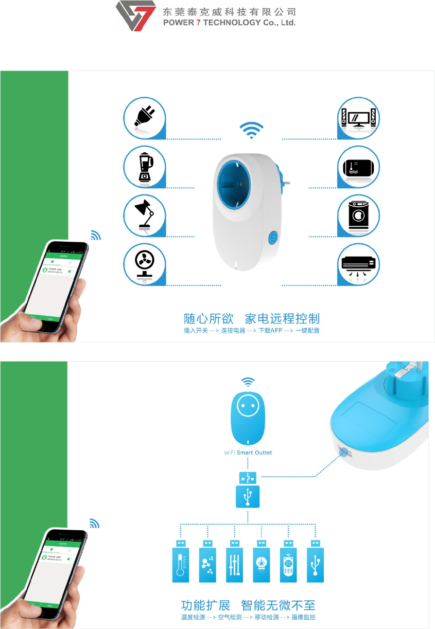
◆ USB Port output 5V/1A.
◆USB HOST, support extensions, allow you to connect USB webcam, USB
temperature and humidity detection equipment, air/smoke detection equipment,
infrared detection equipment. (Optional,Temporarily not supporting this feature).
2.3SoftwareFeatures
◆After the power of smart Outlet is turn on, the smart Outlet can be connected to the
router automatically. According to the environment of the wireless router, the router
can be connected automatically through the app. If automatic connection is not
successful, you need to manually connect.
6
◆Having a switch interface; Can control single or multiple smart Outlets, and display
the listing of the connective smart Outlet.
◆Support electrical energy measurement. And you can select day/week/month/year to
count the quantity of electricity.
◆Timing control interface, you can set the year/month/day/hour/minute/second. You
also can be programmed in cycles (daily/weekly).
◆Scenario setting, according the scenario you can control single or multiple switches.
Also you can edit the name of the different scenarios.
3 Software Parameters
System settings Language settings App can set automatically according to the
phone voice, support for Chinese/English
Firmware upgrades Software and firmware can be upgraded
via a hand-held terminal
Restore the
default settings Restore the system to its original settings
Access control Password protection
A) WI-FI access control:
None
WPA
WPA2
WPA&WPA2
User name / Password
Show the router's user name and password
after Connecting the router (when the
phone is connected for the first time)
Network
management
WAN port Settings
A) Dynamic IP (Direct connect APP or
Wi-Fi Repeater)
B) Automatically/manually connecting to
the router.
Client Android and iOS
4 Application scenarios
7
Smart control of household appliance
USB extension
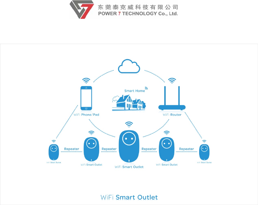
8
WiFi Repeater/Remote control
5. Client Tools
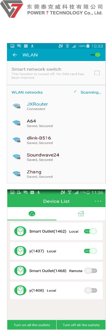
5.1 Login device
1.Clickapp,gointothehomepage.Makesurethesmartphonehasconnected
therouterandtheroutercouldaccesstheinternet.
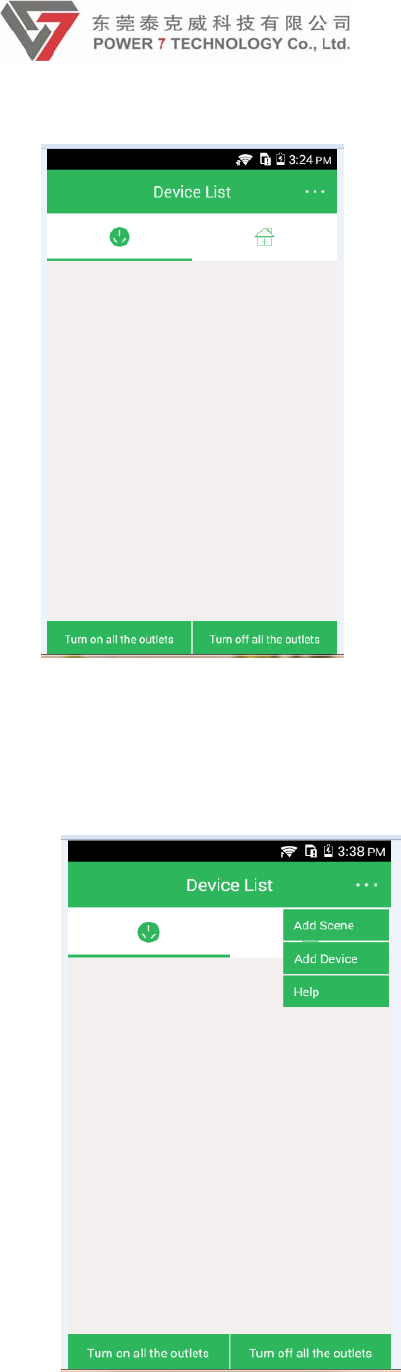
9
【pic】
2.Cilck the drop-down box on the top-right of the home page.Select ‘Add
Device’
【pic】
3.After clicking ‘Add Device’, will go to Environment preparation interface.
Click Next.
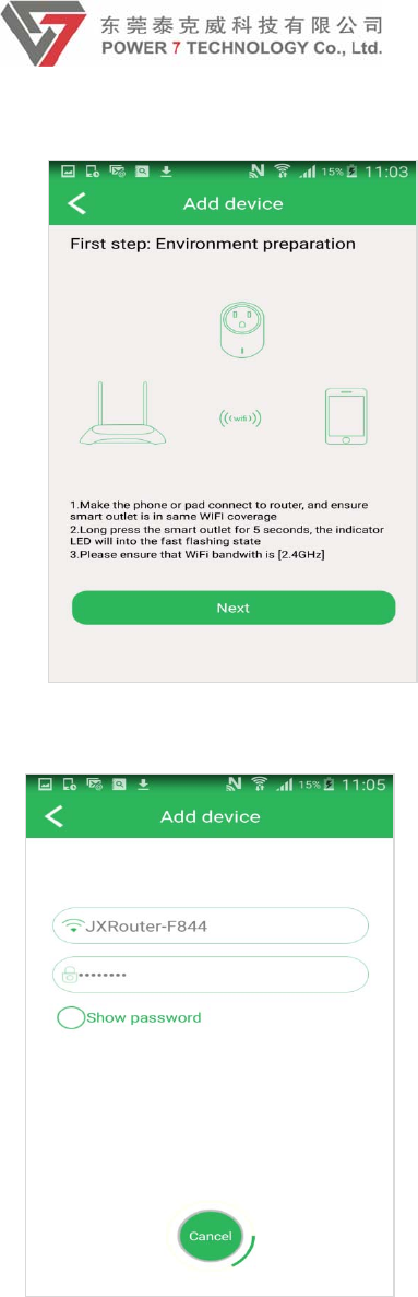
10
4.Enter your correct password of router and click configue. For about 20s,
it will pop up the ‘Add successfully’ message.
【pic】
5.You can find the outlet in the home page
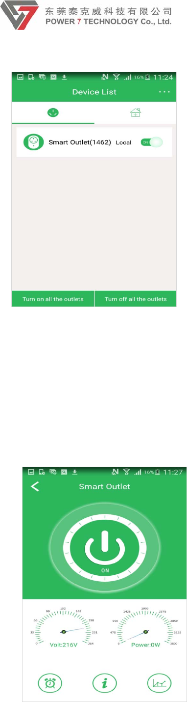
11
【pic】
5.2 Outlet Catalog
1. Click the Smart outlet icon from the device list; go into the
management main interface. You can control your switch on and off by
clicking the big power button showing below. There are also stimulating
voltage and power display. There 3 features in this catalog: Timer
settings, Device information settings and Electric consume graph.
2. Time Zone settings: For the first time, it should be set the time zone
before using the outlet. Since the time zone will affect the timer function. Click
anywhere on the management interface, will pop up the box showing ‘Time
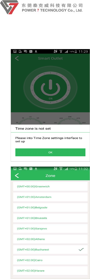
12
zone is not set’. Click OK, will go into the time zone settings interface. Select
the right zone, the time will change to the zone you select.
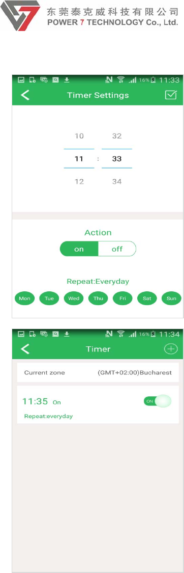
3. Timer settings: Click the clock button on the left below in the page. Then
you can set time for your smart outlet control it turn on or turn off.
13
【pic】
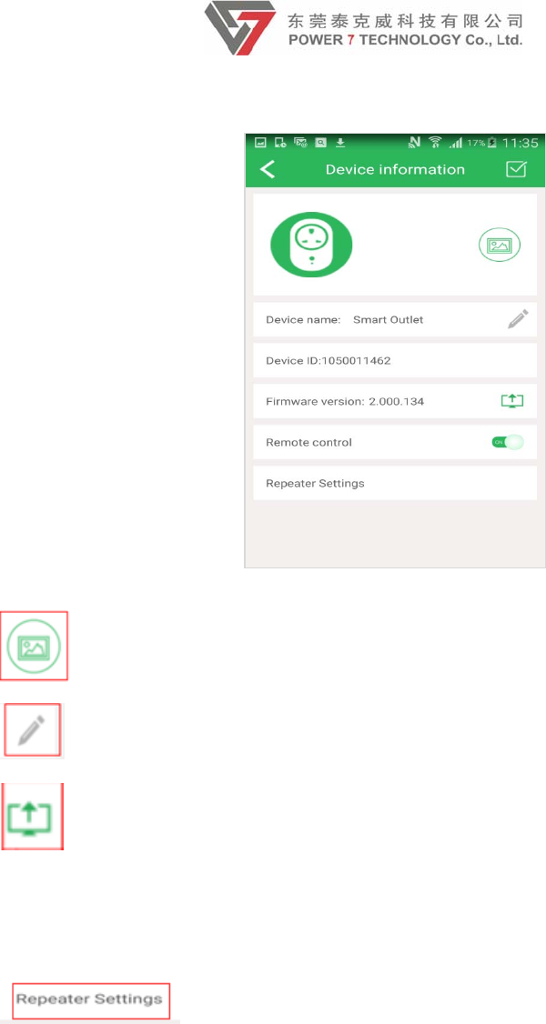
4. Device information setting: Click the “i” style logo in the bottom of the
page. Then you can set your device information.
14
Click this icon, it can change the device icon
Click this icon, it can change the device name
Firmware update:For android app, download the firmware to
smartphone,and then select the FW to upgrade. For iOS app, if the outlet could
access the internet, when the offical website release new firmware, will pop up
a message “New Firmware version detected, download or not ?” Click OK, will
download the firmware.
Repeater Settings: The router and several outlets which
connected the same router consist of the scene 4, the outlet works as a
repeater. End user can control other outlets that connected to the same router
15
【pic】
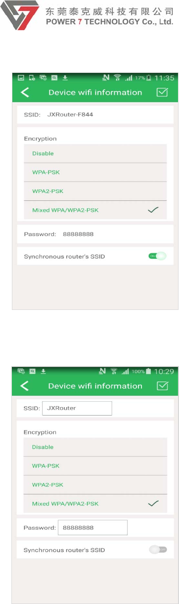
Turn off “Synchronous router’s SSID”, change the SSID and encryption mode,
and then save.
Go into smartphone WiFi settings interface, scan new SSID of outlet and
connect it. Enter into app main interface, will display all the outlets that
connected the same router (Local/LAN) and remote outlet.
16
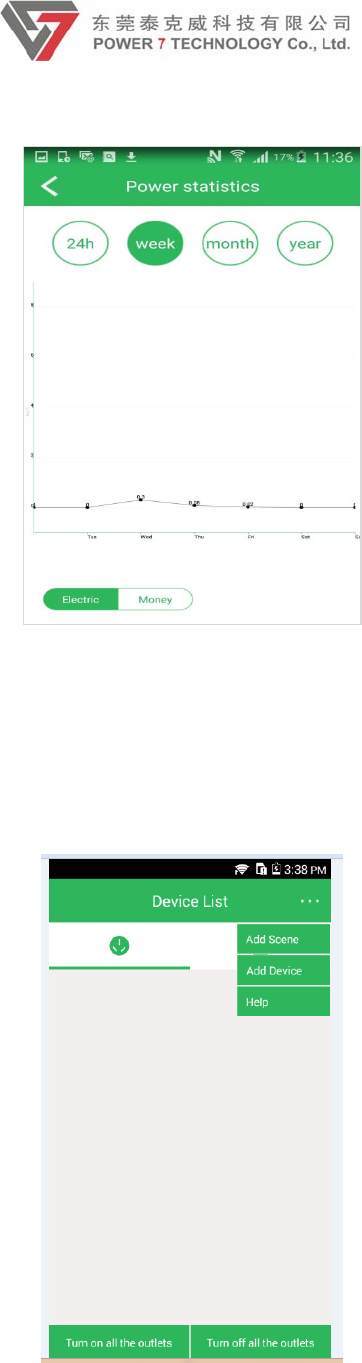
3. Electric consume graph. Click the graph button on the right bottom on the
page and go into electric consume module. This module can calculate the
electric used and its cost.
17
【pic】
5.3 Scene page
1. It is designed for controlling the outlet conveniently in one area. Click the
drop-down box in the right top of the home page, select Add Scene.
【pic】
2.Gointothesceneaddingpage,enterthescenename.click’+’toaddthe
outletyouwantinthescenethensave.
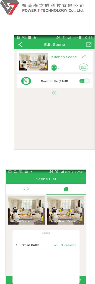
18
3. You can control all the outlets in the same scene by click the scene only.
5.4 Remote access
After you connect to the smart outlet or the router that outlet connected, you can
control the outlet via WiFi/2G/3G/4G anywhere, anytime. Also can check the outlet
status.

19
FCC Statement
This equipment has been tested and found to comply with the limits for a Class B digital device,
pursuant to part 15 of the FCC Rules. These limits are designed to provide reasonable protection
against harmful interference in a residential installation. This equipment generates, uses and can
radiate radio frequency energy and, if not installed and used in accordance with the instructions,
may cause harmful interference to radio communications. However, there is no guarantee that
interference will not occur in a particular installation. If this equipment does cause harmful
interference to radio or television reception, which can be determined by turning the equipment off
and on, the user is encouraged to try to correct the interference by one or more of the following
measures:
—Reorient or relocate the receiving antenna.
—Increase the separation between the equipment and receiver.
—Connect the equipment into an outlet on a circuit different from that to which the receiver is
connected.
—Consult the dealer or an experienced radio/TV technician for help.
FCC Radiation Exposure Statement
This device complies with FCC radiation exposure limits set forth for an uncontrolled environment
and it also complies with Part 15 of the FCC RF Rules. This equipment must be installed and
operated in accordance with provided instructions and the antenna(s) used for this transmitter must
be installed to provide a separation distance of at least 20 cm from all persons and must not be
co-located or operating in conjunction with any other antenna or transmitter. End-users and
installers must be provided with antenna installation instructions and consider removing the
no-collocation statement.
This device complies with Part 15 of the FCC Rules. Operation is subject to the following two
conditions:
(1) this device may not cause harmful interference, and
(2) this device must accept any interference received, including interference that may cause
undesired operation.
Caution!
Any changes or modifications not expressly approved by the party responsible for compliance could
void the user's authority to operate the equipment.