Power Pro (Glt) 5500 User Manual 13HP GENERATOR Manuals And Guides L0522090
POWER PRO (GLT) Generator Manual L0522090 POWER PRO (GLT) Generator Owner's Manual, POWER PRO (GLT) Generator installation guides
User Manual: Power Pro (Glt) 5500 5500 POWER PRO (GLT) 13HP GENERATOR - Manuals and Guides View the owners manual for your POWER PRO (GLT) 13HP GENERATOR #5500. Home:Tool Parts:Power Pro (Glt) Parts:Power Pro (Glt) 13HP GENERATOR Manual
Open the PDF directly: View PDF ![]() .
.
Page Count: 30
MODEL 5500
13 HP Generator
Item # 56550
Owner's Manual
DO NOT RETURN TO
STORE
Questions? Problems?
Please call our customer
help line:
(888) 315-3080 M-F 8-5
CT
ThaN< you for purchasing a model 5500 generator. This manual provides information regarding
the operation and maintenance of this product. We have made every effort to ensure the accuracy
of the information in this manual. Wen Power reserves the right to change this product at any time
without prior notice.
Please keep this manual available to all users during the entire life of the generator.
rex'. 03/24/05
MODEL 5500
13 HP Generator
FEATURES
•5500 Surge Watt Output
•5000 Rated Watt Output
•Powerful Enough to Run Essential Appliances
During Power Outages
•120 and 240 VoltAC Outputs
•DC Output for Automotive Battery Charging
•Low OilAutomaticShutoff
•Circuit Breaker for Overload Protection
•6.5 Gallon Fuel Tank Capacity
•Meets EPA Emission Standards
TABLE OF CONTENTS
GENERAL SAFETY PROCEDURES ........................................................................ 4
PACKAGE CONTENTS ....................................................................................... 8
GENERATOR COMPONENTS .............................................................................. 9
PREPARING THE GENERATOR FOR USE ............................................................... 10
Using the Generator tbr the First Time ............................................................... 10
Step 1- Add Oil ................................................................................. 10
Step 2- Add Gasoline .......................................................................... 11
Step 3- Ground the Generator ................................................................ 11
Subsequem Use of the Generator ..................................................................... 12
Step 1- Check the Oil .......................................................................... 12
Step 2- Check the Gas Level ................................................................. 12
Step 3- Ground the Generator ................................................................ 13
STARTING THE GENERATOR .............................................................................. 13
USING THE GENERATOR ................................................................................... 14
AC Usage ................................................................................................ 14
DC Usage ................................................................................................ 17
STOPPING THE GENERATOR .............................................................................. 18
MAINTENANCE /CARE ..................................................................................... 19
Cleaning the Generator ................................................................................. 19
Checking the Oil ........................................................................................ 19
Changing/Adding Oil .................................................................................. 20
Air Cleaner Maintenance .............................................................................. 21
Fuel Filter Cup Cleaning .............................................................................. 22
Spark Plug Maintenance ............................................................................... 22
Emptying the Gas Tank ................................................................................ 23
STORAGE /TRANSPORT PROCEDURES ............................................................... 23
SPECIFICATIONS .............................................................................................. 24
TROUBLESHOOTING ......................................................................................... 25
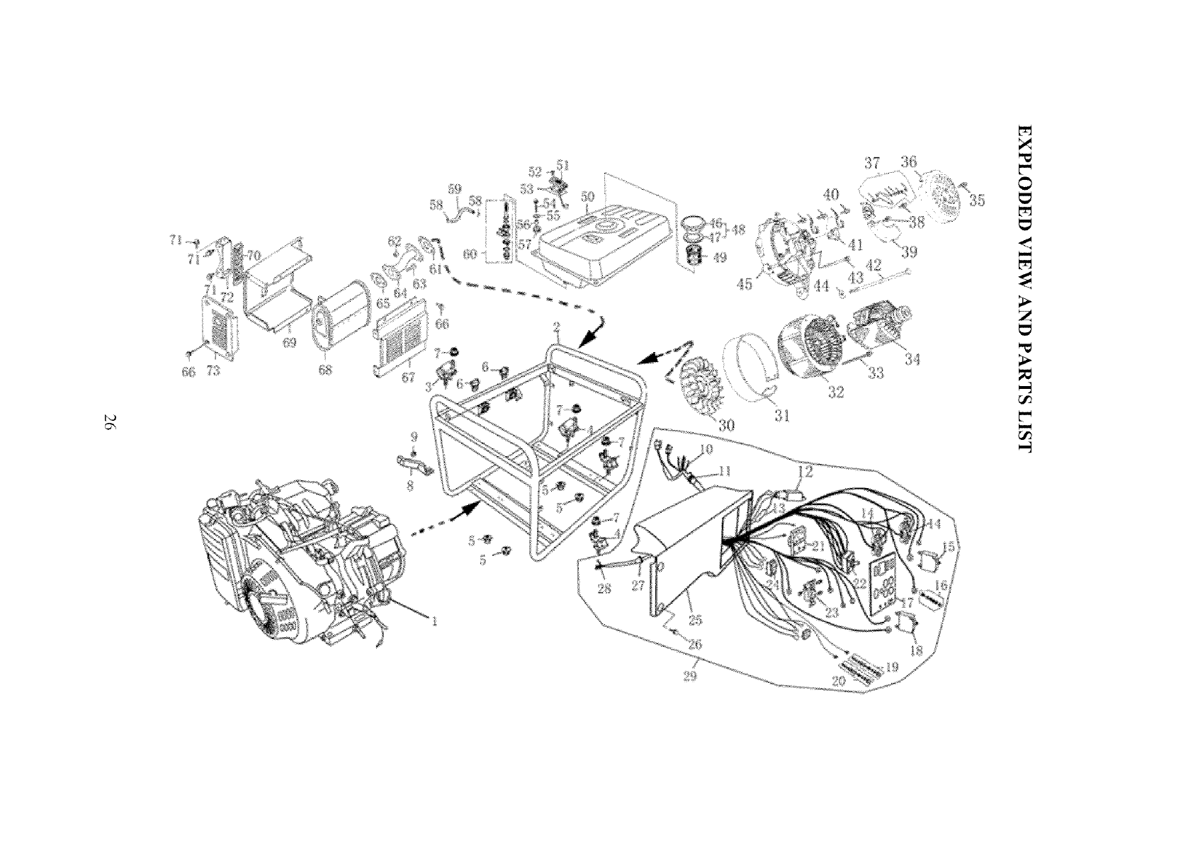
EXPLODED VIEW AND PARTS LIST ..................................................................... 26
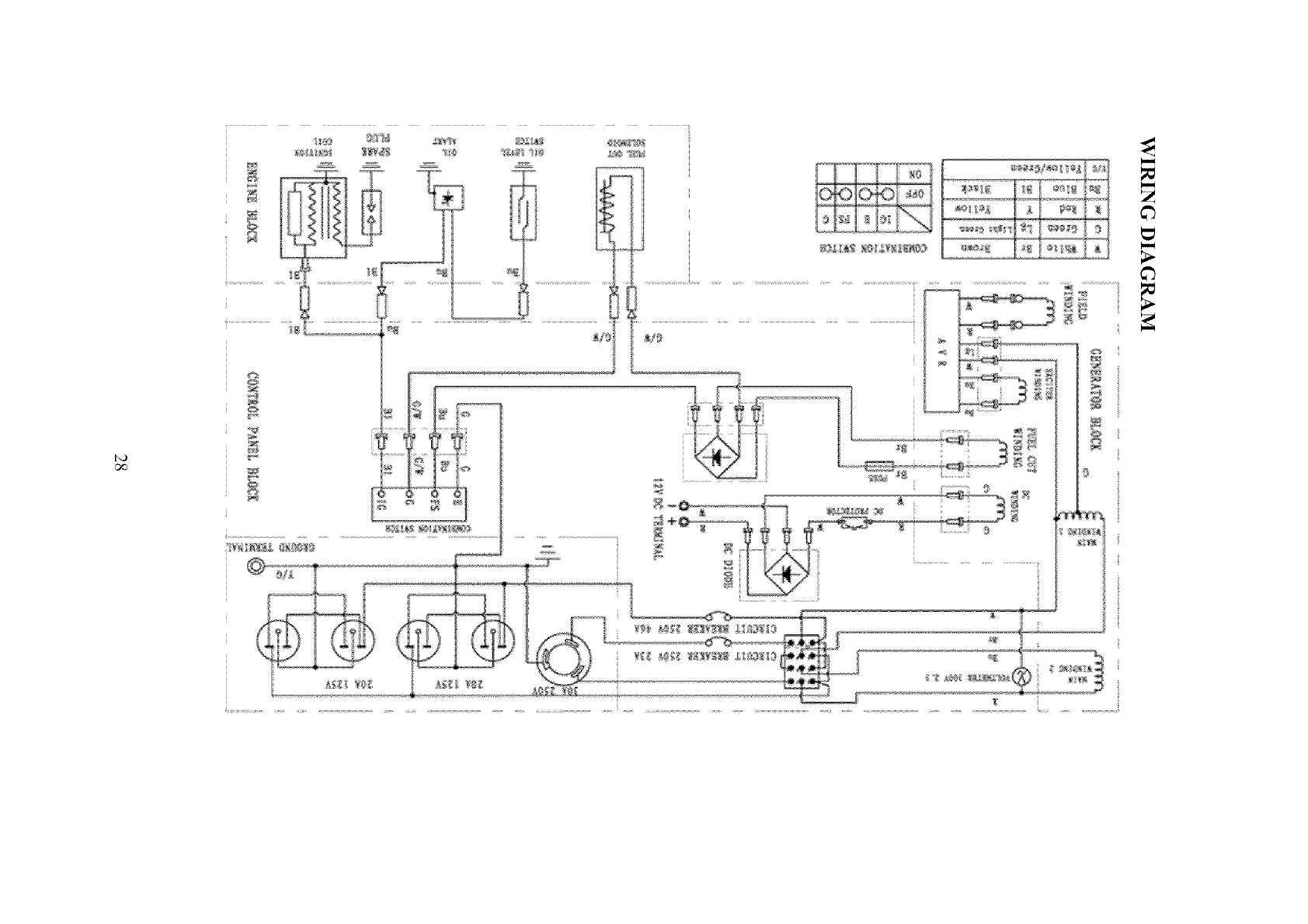
WIRING DIAGRAM ........................................................................................... 28
WARRANTY ..................................................................................................... 30
Notice Regarding Emissions
Engines that are certified to comply with U.S. EPA emission regulations for SORE
(Small Off Road Equipment), are certified to operate on regular unleaded gasoline, and
may include the tbllowing emission control systems: (EM) Engine Modifications and
(TWC) Three-Way Catalyst (if so equipped).
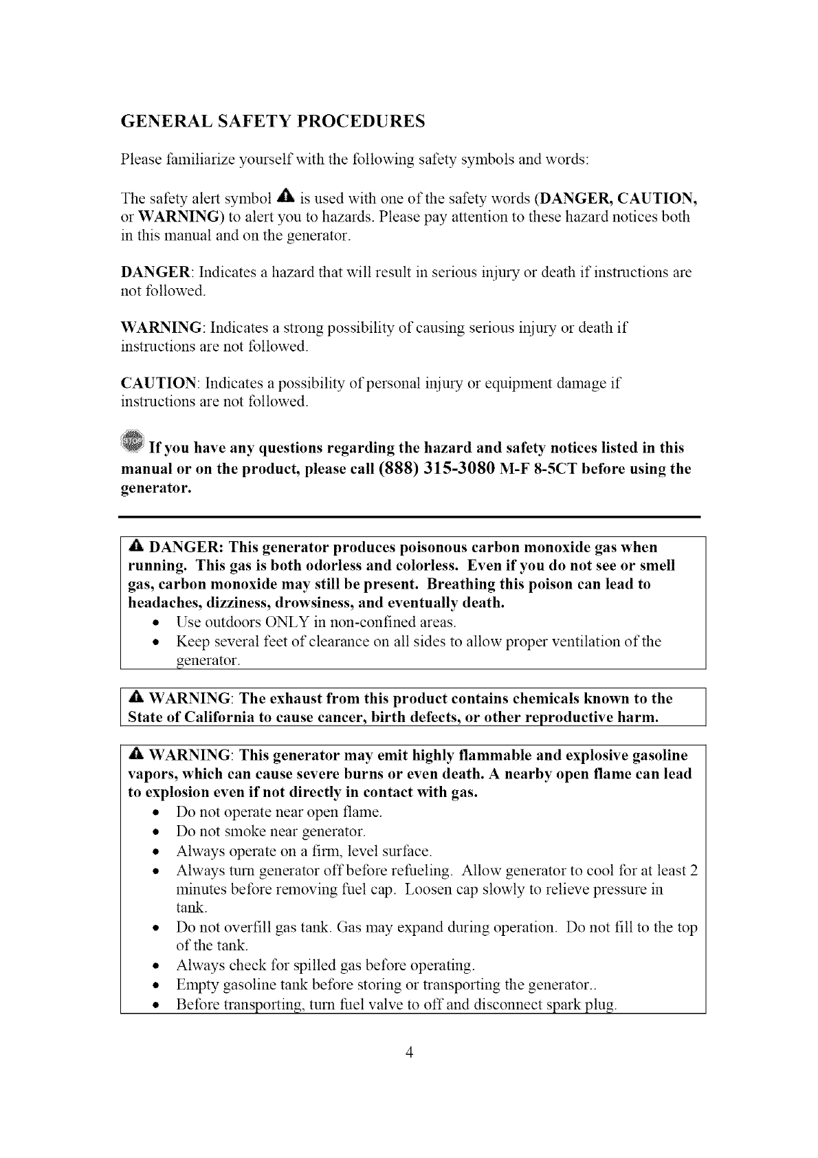
GENERAL SAFETY PROCEDURES
Please familiarize yourself with the lbllowing safety symbols and words:
The safety alert symbol _t, is used with one of the safety words (DANGER, CAUTION,
or WARNING) to alert you to hazards. Please pay attention to these hazard notices both
in this manual and on the generator.
DANGER: Indicates a hazard that will result in serious injury or death if instructions are
not followed.
WARNING: Indicates a strong possibility of causing serious injury or death if
instructions are not lbllowed.
CAUTION: Indicates a possibility of personal injury or equipment damage if
instructions are not followed.
If you have any questions regarding the hazard and safety notices listed in this
manual or on the product, please call (888) 315-3080 M-F 8-5CT before using the
generator.
AlLDANGER: This generator produces poisonous carbon monoxide gas when
running. This gas is both odorless and colorless. Even if you do not see or smell
gas, carbon monoxide may still be present. Breathing this poison can lead to
headaches, dizziness, drowsiness, and eventually death.
• Use outdoors ONLY in non-confined areas.
• Keep several feet of clearance on all sides to allow proper ventilation of the
generator.
A WARNING: The exhaust from this product contains chemicals known to the
State of California to cause cancer, birth defects, or other reproductive harm.
WARNING: This generator may emit highly flammable and explosive gasoline
vapors, which can cause severe burns or even death. A nearby open flame can lead
to explosion even if not directly in contact with gas.
• Do not operate near open flame.
• Do not smoke near generator.
• Always operate on a finn, level surface.
• Always turn generator off before refueling. Allow generator to cool for at least 2
minutes betbre removing fuel cap. Loosen cap slowly to relieve pressure in
tank.
• Do not overfill gas tank. Gas may expand during operation. Do not fill to the top
of the tank.
• Always check for spilled gas before operating.
• Empty gasoline tank before storing or transporting the generator..
• Betbre transporting, turn fuel valve to off and disconnect spark plug.
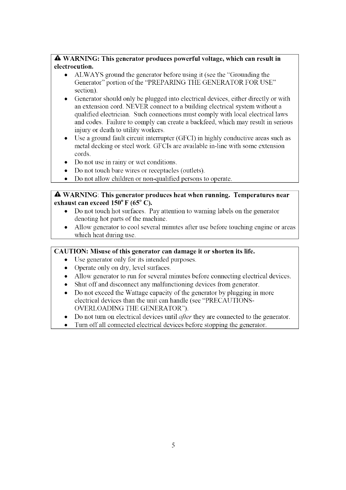
WARNING: This generator produces powerful voltage, which can result in
electrocution.
• ALWAYS ground the generator betbre using it (see the "Grounding the
Generator" portion of the "PREPARING THE GENERATOR FOR USE"
section).
• Generator should only be plugged into electrical devices, either directly or with
an extension cord. NEVER connect to a building electrical system without a
qualified electrician. Such connections must comply with local electrical laws
and codes. Failure to comply can create a backfeed, which lrlay result in serious
iniury or death to utility workers.
• Use a ground fault circuit interrupter (GFCI) in highly conductive areas such as
metal decking or steel work. GFCIs are available in-line with solne extension
cords.
• Do not use in rainy or wet conditions.
• Do not touch bare wires or receptacles (outlets).
• Do not allow children or non-qualified persons to operate.
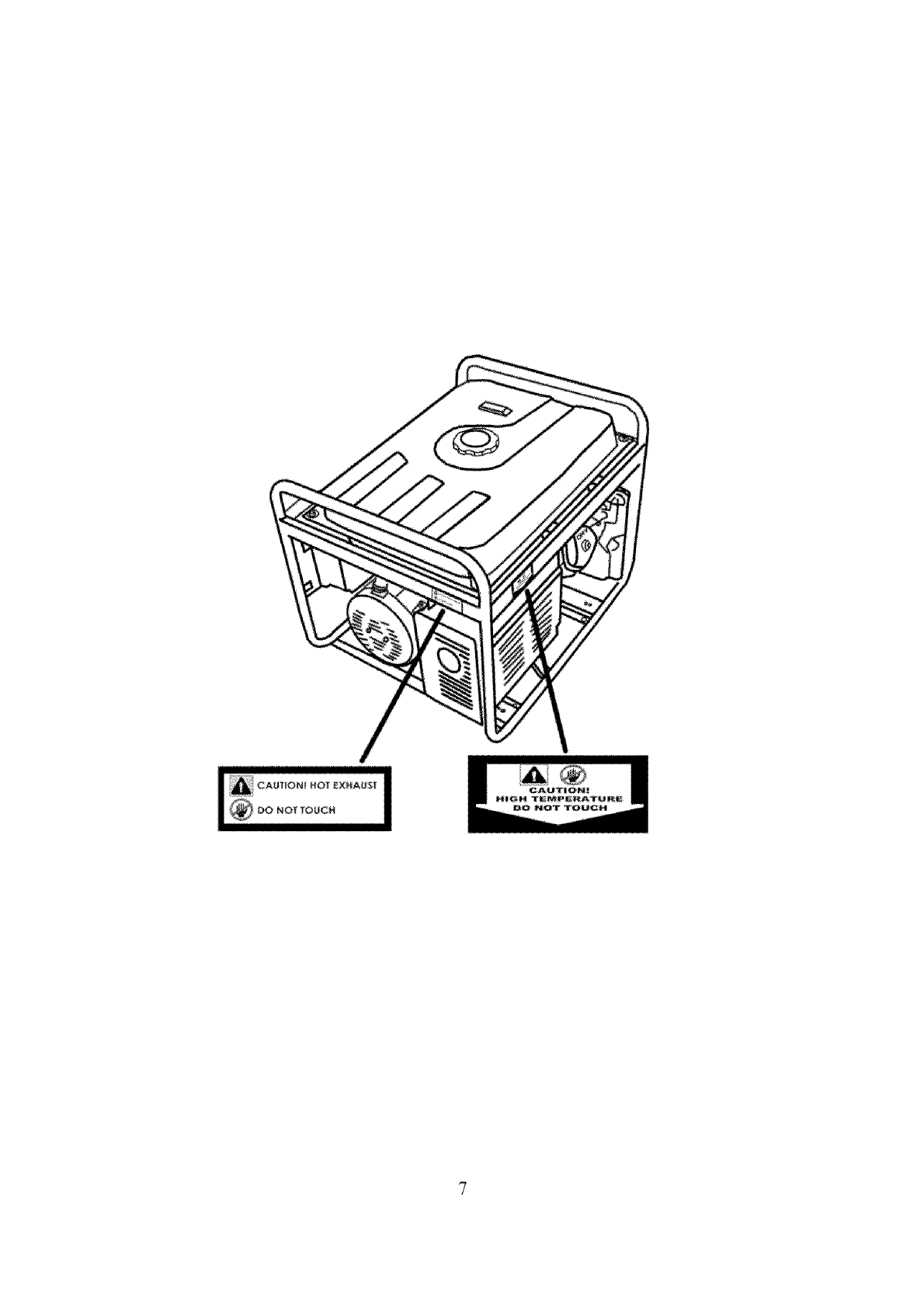
A WARNING: This generator produces heat when running. Temperatures near
exhaust can exceed 150° F (65 ° C).
• Do not touch hot surfaces. Pay attention to warning labels on tire generator
denoting hot parts of tire machine.
• Allow generator to cool several minutes after use before touching engine or areas
which heat during use.
CAUTION: Misuse of this generator can damage it or shorten its life.
• Use generator only for its intended purposes.
• Operate only on dry, level surfaces.
• Allow generator to run for several minutes betbre connecting electrical devices.
• Shut off and disconnect any malfunctioning devices t}oln generator.
• Do not exceed the Wattage capacity of tire generator by plugging in more
electrical devices than tire unit can handle (see "PRECAUTIONS-
OVERLOADING THE GENERATOR").
• Do not turn on electrical devices umil after they are connected to the generator.
• Turn off all connected electrical devices betbre stopping the generator.
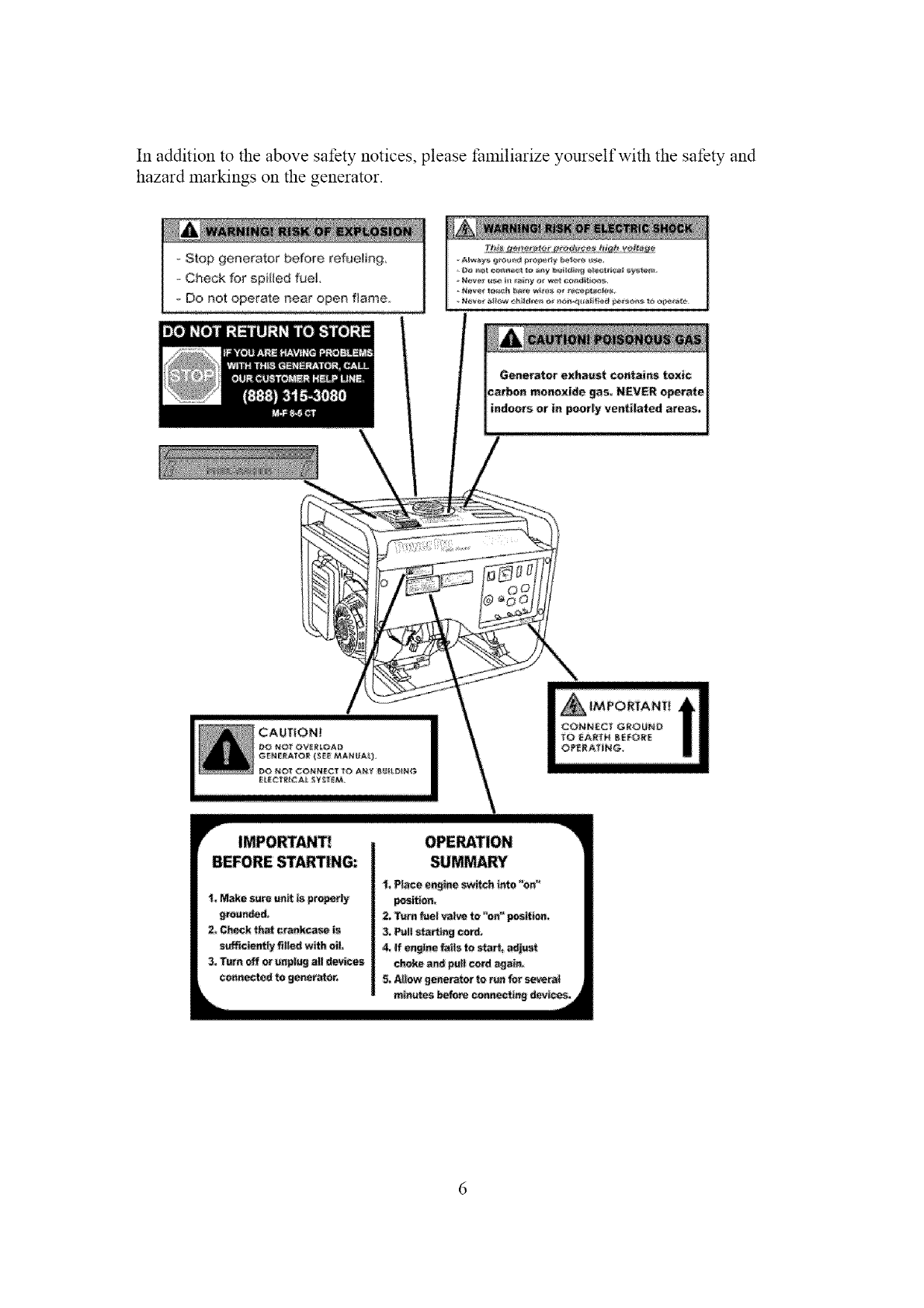
In addition to the above safety notices, please familiarize yourself with the safety and
hazard markings on the generator.
Stop generator before refueling
- Check for spilled fuel,
Do not operate near open flame,
IMPORTANT_
BEFORE STARTING::
_, Mak_ s_e _tt is p_ope_ly
9tour_ed,
2. Gh_ck {hat ¢r_N_ is
3. Turn _ N _r_lu_ NI d_vCceg
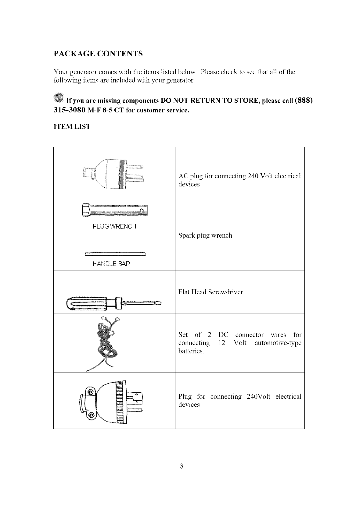
PACKAGE CONTENTS
Your generator comes with the items listed below. Please check to see that all of the
tbllowing items are included with your generator.
If you are missing components DO NOT RETURN TO STORE, please call (888)
315-3080 M-F 8-5 CT for customer service.
ITEM LIST
..................
G
PLUG WRENCH
HANDLE BAR
AC plug tbr connecting 240 Volt electrical
Spark plug wrench
Flat Head Screwdriver
Set of 2 DC connector wires t_r
connecting 12 Volt automotive-type
batteries.
Plug tbr connecting 240Volt electrical
devices
devices
GENERATOR COMPONENTS
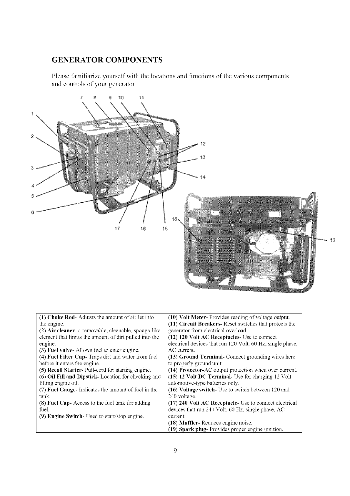
Please familiarize yourself with the locations and functions of the various components
and controls of your generator.
78 9 10 t 1
1
2
4
17 _8 !5
t2
!4
19
(1) Choke Rod- Adjusts the amount of air let into
the engine.
(2) Air cleaner- a removable, cleanable, sponge-like
element that limits the amount of dirt pulled into the
engine.
(3) Fuel valve- Allows fuel to enter engine.
(4) Fuel Filter Cup- Traps dirt and water fi:om fuel
before it enters the engine.
(5) Recoil Starter- Pull-cord l_r starting engine.
(6) Oil Fill and Dipstick- Location l_r checking and
filling engine oil.
(7) Fuel Gauge- Indicates the amount of fuel in the
tank.
(8) Fuel (ap- Access to the fuel tank for adding
fuel.
(9) Engine Switch- Used to start/stop engine.
(10) Volt Meter- Provides reading of voltage output.
(11) Circuit Breakers- Reset switches that protects the
generator I?oln electrical overload.
(12) 120 Volt AC Receptacles- Use to connect
electrical devices that run 120 Volt, 60 Hz, single phase,
AC current.
(13) Ground Terminal- Connect grounding wires here
to properly ground unit.
(14) Protector-AC output protection when over current.
(15) 12 Volt DC Terminal- Use I_r charging 12 Volt
automotive-type batteries only.
(16) Voltage switch- Use to switch between 120 and
240 voltage.
(17) 240 Volt AC Receptacle- Use to connect electrical
devices that run 240 Volt, 60 Hz, single phase, AC
current.
(18) Muffler- Reduces engine noise.
(19) Spark plug- Provides proper engine ignition.
PREPARING THE GENERATOR FOR USE
Usin_ the Generator for the First Time
@The following section describes steps you must follow to prepare your generator
for first-time use. If after reading this" section, you are unsure about how to perform
any of the steps please call (888) 315-3080 M-F 8-5 CT for customer service.
Failure to perform these steps properly can damage your generator or shorten its" life.
If you are using the generator for the first time, there are a few steps you must take to
prepare it for operation:
Step 1- Add oil
The generator requires engine oil to operate properly. The generator, when new [_Oln the
package, contains 17o oil in the crankcase. You must add the proper amount ofoil before
operating the generator for the first time. This amount, which is equal to the oil capacity
of the engine crankcase, is 37 fluid oz.
For general use, we recommend SAE 10W/30 oil to fill the engine crankcase.
To add oil, tbllow these steps:
1. Make sure the generator is on a level surface.
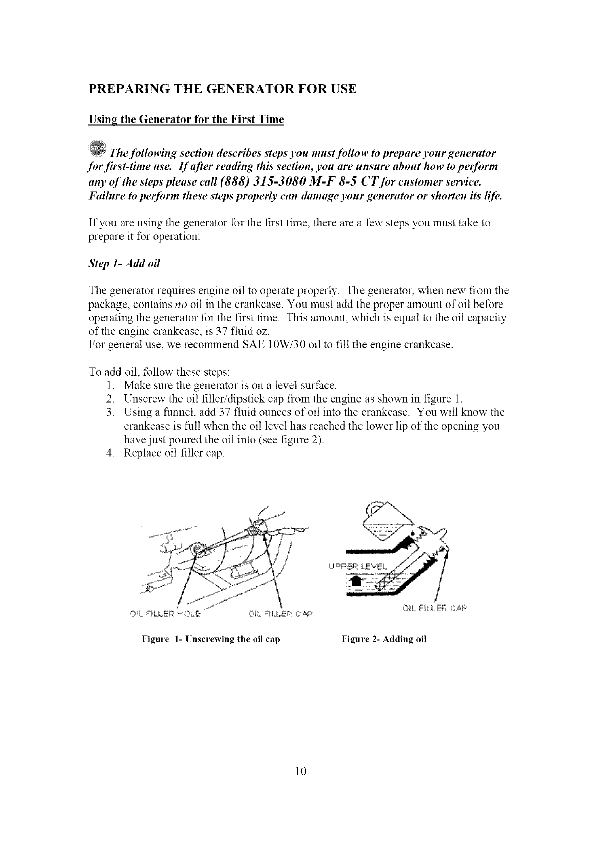
2. Unscrew the oil filler/dipstick cap t_Oln the engine as shown in figure 1.
3. Using a funnel, add 37 fluid ounces ofoil into the crankcase. You will know the
crankcase is full when the oil level has reached the lower lip of the opening you
have just poured the oil into (see figure 2).
4. Replace oil filler cap.
OH, FiLLiP HO[ _!_ Oi_ FILLER CAP
Figure 1- Unscrewing the oil cap
OiL FiLLEI;_'OAFs'
Figure 2- Adding oil
10
Step 2- Add Gasoline
_1_WARNING: Gasoline and gas fumes are highly flammable.
•Do not fill tank near an open flame.
•Do not overfill. Always check for fuel spills.
To ensure that the generator runs Slnoothly use only FRESH, UNLEADED GAS WITH
AN OCTANE RATING OF 87 OR HIGHER. To add gasoline:
1. Make sure the generator is on a level surface.
2. Unscrew gas cap and set aside (NOTE: the gas cap may be tight and hard to
unscrew).
3. Slowly add unleaded gasoline to the fuel tank. The capacity of the gas tank is 6.5
gallons. Be careful not to overfill. The fuel gauge on the top of the generator
indicates how much gasoline is in the generator gas tank. NOTE: Gas can expand.
Do not fill the gas tank to the very top.
4. Replace fuel cap and wipe up any spilled gasoline with a dry cloth.
IMPORTANT:
• Never use an oil/gasoline mixture.
• Never use old gas.
• Avoid getting dirt or water in the fuel taN<.
• Gas can age in the tank and make it hard to start up the generator in the future.
Never store generator tbr extended periods of time with fuel in the tank.
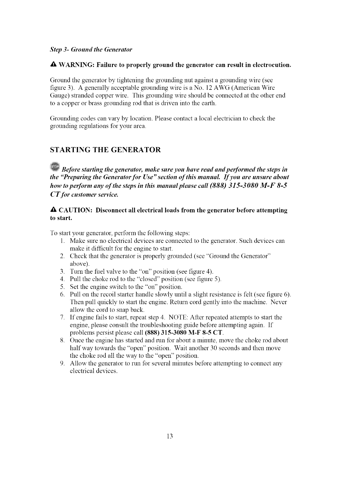
Step 3- Ground the Generator
_i_ WARNING: Failure to properly ground the generator can result in electrocution.
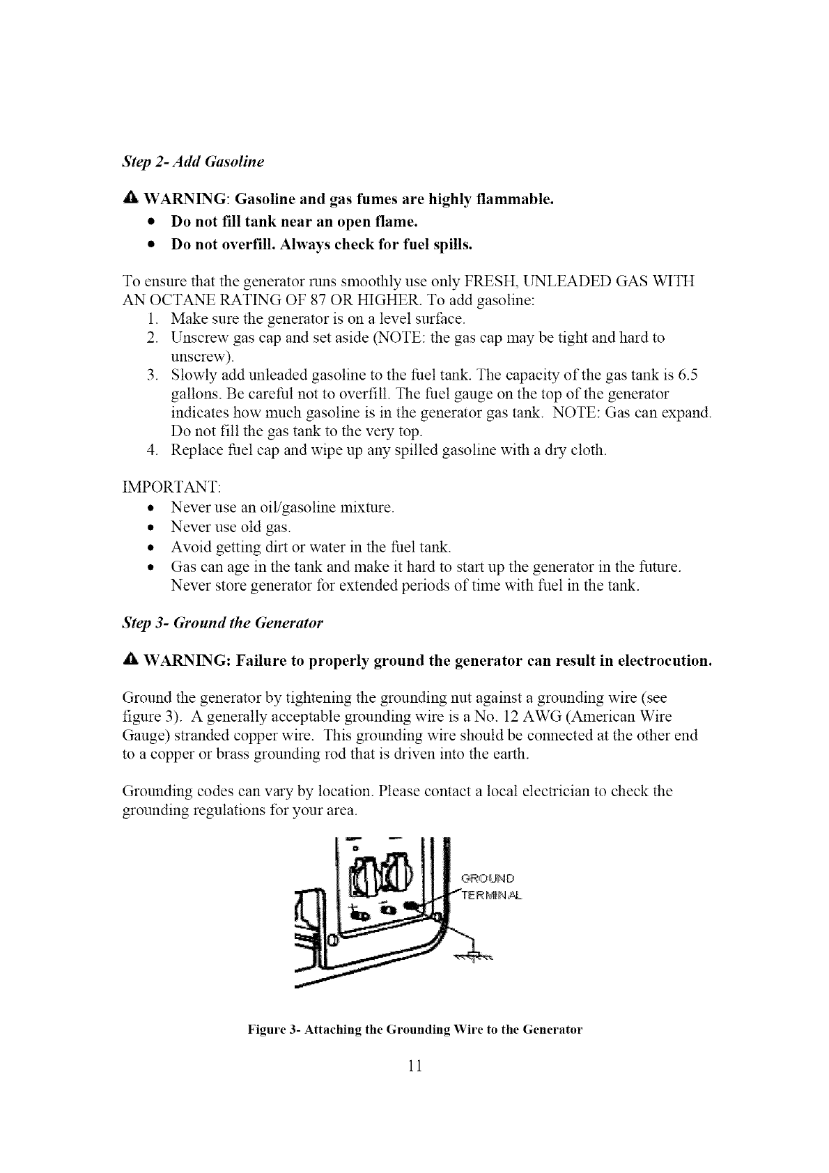
Ground the generator by tightening the grounding nut against a grounding wire (see
figure 3). A generally acceptable grounding wire is a No. 12 AWG (American Wire
Gauge) stranded copper wire. This grounding wire should be connected at the other end
to a copper or brass grounding rod that is driven into the earth.
Grounding codes can vary by location. Please contact a local electrician to check the
grounding regulations for your area.
Figure 3- Attaching the Grounding Wire to the Generator
11
Subsequent Use of the Generator
If this is not your first time using the generator there are still steps you should take to
prepare it tbr operation.
IMPORTANT: At this point you should be familiar with the procedures described
in the first portion of this section entitled "Using the Generator for the First Time."
If you have not yet read this section, go back and read it now.
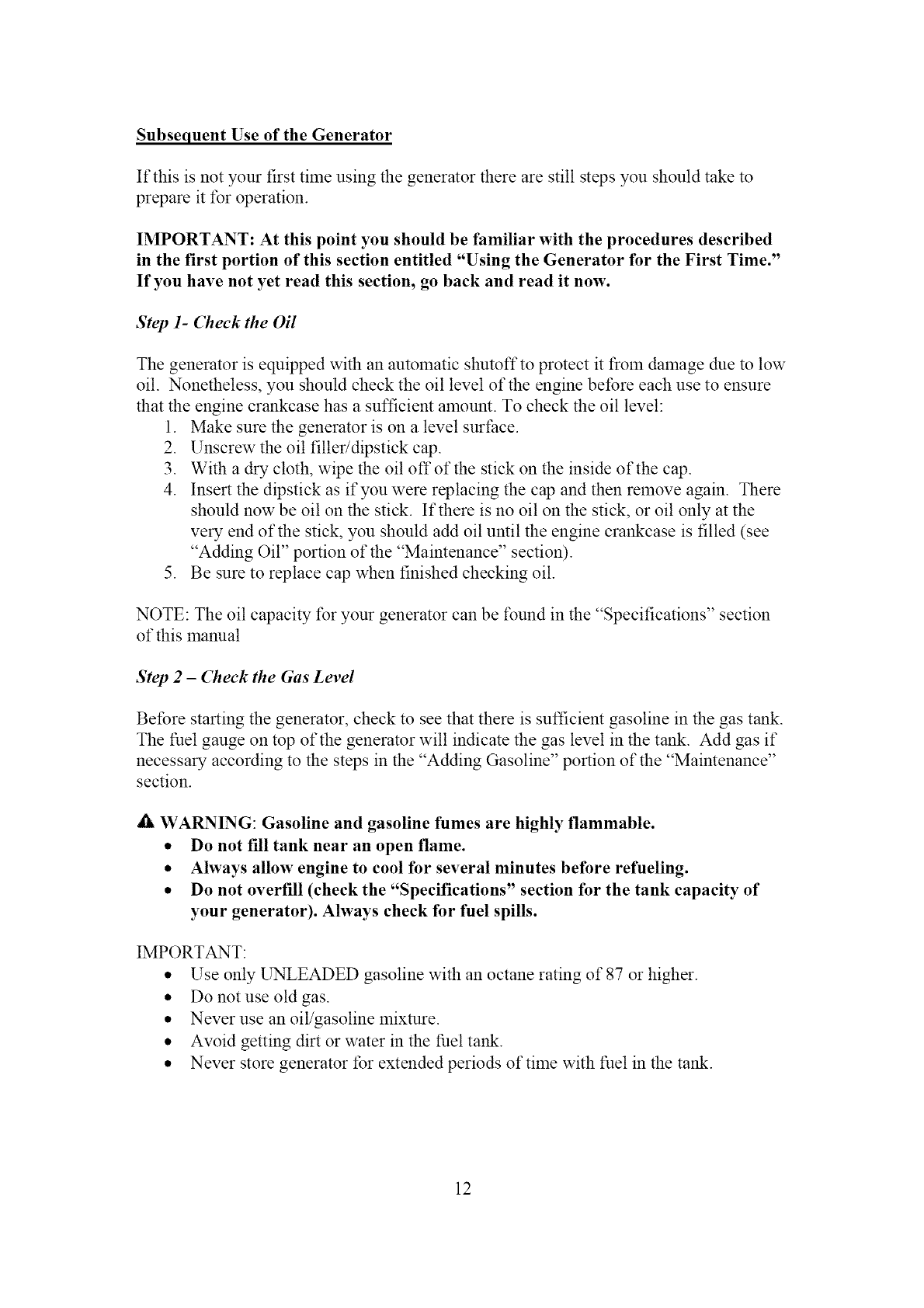
Step 1- Check the Oil
The generator is equipped with an automatic shutoffto protect it froln damage clue to low
oil. Nonetheless, you should check the oil level of the engine before each use to ensure
that the engine crankcase has a sufficient alnount. To check the oil level:
1. Make sure the generator is on a level surface.
2. Unscrew the oil filler/dipstick cap.
3. With a dry cloth, wipe the oil offofthe stick on the inside of the cap.
4. Insert the dipstick as if you were replacing the cap and then remove again. There
should now be oil on the stick. If there is no oil on the stick, or oil only at the
very end of the stick, you should add oil until the engine crankcase is filled (see
"Adding Oil" portion of the "Maintenance" section).
5. Be sure to replace cap when finished checking oil.
NOTE: The oil capacity tbr your generator can be found in the "Specifications" section
of this manual
Step 2 -Check the Gas Level
Betbre starting the generator, check to see that there is sufficient gasoline in the gas tank.
The fuel gauge on top of the generator will indicate the gas level in the tank. Add gas if
necessary according to the steps in the "Adding Gasoline" portion of the "Maintenance"
section.
dk WARNING: Gasoline and gasoline fumes are highly flammable.
•Do not fill tank near an open flame.
•Always allow engine to cool for several minutes before refueling.
•Do not overfill (check the "Specifications" section for the tank capacity of
your generator). Always check for fuel spills.
IMPORTANT:
• Use only UNLEADED gasoline with an octane rating of 87 or higher.
• Do not use old gas.
• Never use an oil/gasoline mixture.
• Avoid getting dirt or water in the fuel tank.
• Never store generator tbr extended periods of time with fuel in the tank.
12
Step 3- Ground the Generator
AWARNING: Failure to properly ground the generator can result in electrocution.
Ground the generator by tightening the grounding nut against a grounding wire (see
figure 3). A generally acceptable grounding wire is a No. 12 AWG (American Wire
Gauge) stranded copper wire. This grounding wire should be connected at the other end
to a copper or brass grounding rod that is driven into the earth.
Grounding codes can vary by location. Please contact a local electrician to check the
grounding regulations for your area.
STARTING THE GENERATOR
Before starting the generator, make sure you have read and performed the steps in
the "Preparing the Generator for Use" section of this manual. If you are unsure about
how to pelform any of the steps in this" manual please call (888) 315-3080 M-F 8-5
CT for customer service.
A CAUTION: Disconnect all electrical loads from the generator before attempting
to start.
To start your generator, pertbrln the tbllowing steps:
1. Make sure no electrical devices are connected to the generator. Such devices can
make it difficult for the engine to start.
2. Check that the generator is properly grounded (see "Ground the Generator"
above).
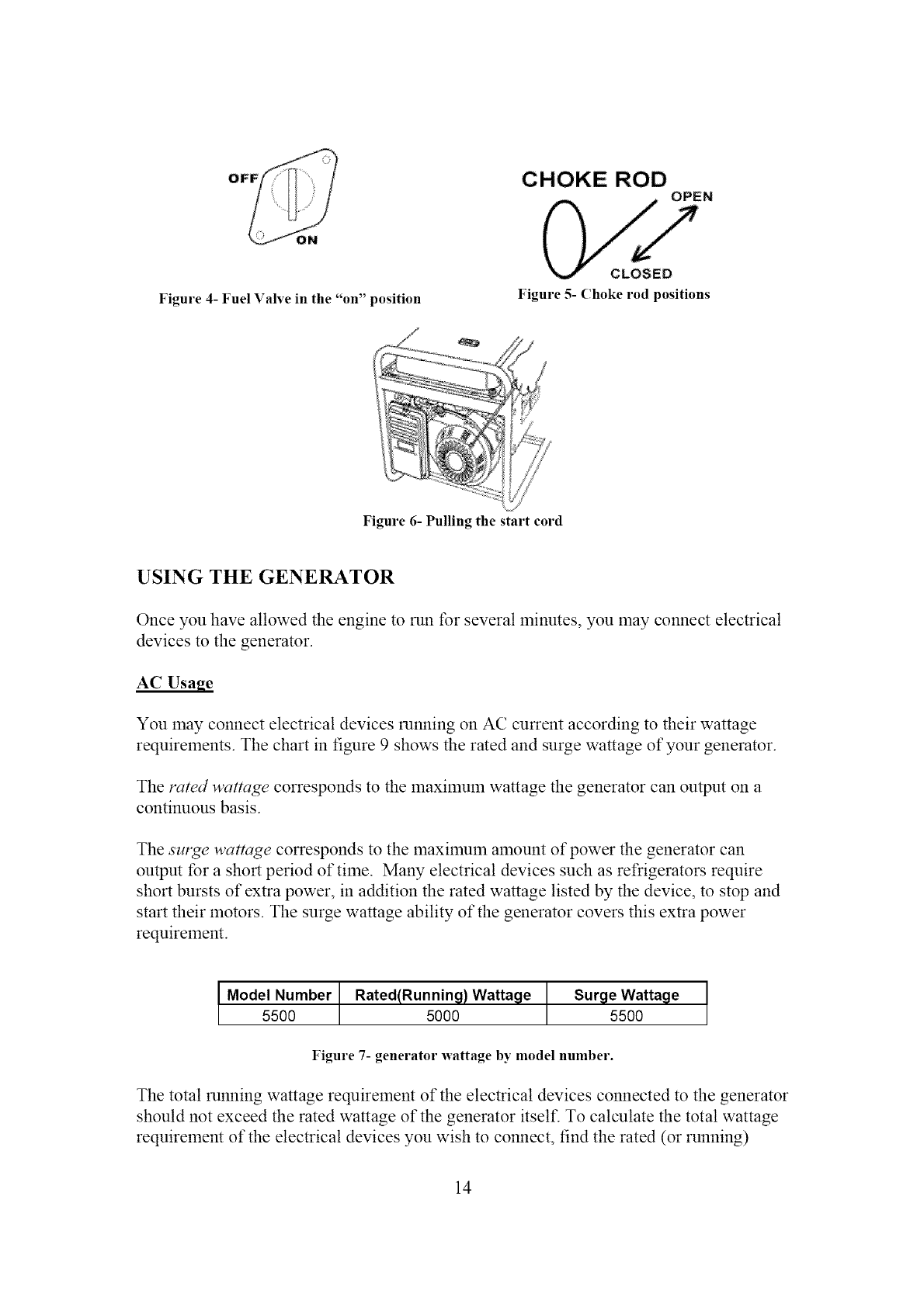
3. Turn the fuel valve to the "on" position (see figure 4).
4. Pull the choke rod to the "closed" position (see figure 5).
5. Set the engine switch to the "on" position.
6. Pull on the recoil starter handle slowly until a slight resistance is felt (see figure 6).
Then pull quickly to start the engine. Return cord gently into the machine. Never
allow the cord to snap back.
7. If engine thils to start, repeat step 4. NOTE: After repeated attempts to start the
engine, please consult the troubleshooting guide betbre attempting again. If
problelns persist please call (888) 315-3080 M-F 8-5 CT.
8. Once the engine has started and run tbr about a minute, move the choke rod about
halfway towards the "open" position. Wait another 30 seconds and then move
the choke rod all the way to the "open" position.
9. Allow the generator to run tbr several minutes before attempting to connect any
electrical devices.
13
OFF CHOKE ROD
OPEN
Figure 4- Fuel Valve in the "on" position
CLOSED
Figure 5- (hoke rod positions
Figure 6- Pulling the start cord
USING THE GENERATOR
Once you have allowed the engine to run for several minutes, you may connect electrical
devices to the generator.
AC Usage
You may connect electrical devices minting on AC current according to their wattage
requirements. The chart in figure 9 shows the rated and surge wattage of your generator.
The rated wattage corresponds to the maximum wattage the generator can output on a
continuous basis.
The sm2qe wattage corresponds to the maximum amount of power the generator can
output for a short period of time. Many electrical devices such as refrigerators require
short bursts of extra power, in addition the rated wattage listed by the device, to stop and
start their motors. The surge wattage ability of the generator covers this extra power
requirement.
IModel Number Rated(Runnin_t) Watta_te Sur_te Watta_te
5500 5000 5500
Figure 7- generator wattage by model number.
The total running wattage requirement of the electrical devices connected to the generator
should not exceed the rated wattage of the generator itself: To calculate the total wattage
requirement of the electrical devices you wish to connect, find the rated (or running)
14
wattageof eachdevice.Thisnumbershouldbelistedsomewhereonthedeviceor in its
instructionmanual.If youcannotfindthiswattage,you maycalculateit bymultiplying
theVoltagerequirementbytheAmperagedrawn:
Watts= Voltsx Amperes
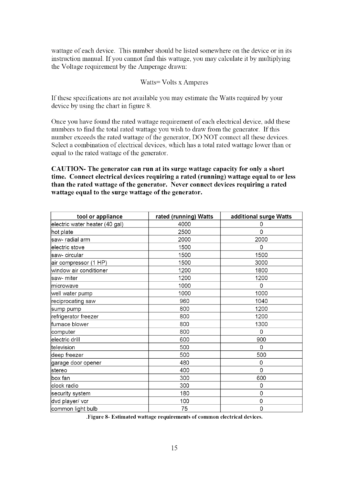
If thesespecificationsarenotavailableyoumayestimatetheWattsrequiredbyyour
devicebyusingthechartin figure8.
Onceyouhavefoundtheratedwattagerequirementof eachelectricaldevice,addthese
numbersto findthetotalratedwattageyou wishto drawfrom thegenerator.If this
numberexceedstheratedwattageof thegenerator,DONOT connectall thesedevices.
Selectacombinationof electricaldevices,whichhasatotalratedwattagelowerthanor
equalto theratedwattageof thegenerator.
CAUTION- Thegenerator can run at its surge wattage capacity for only ashort
time. Connect electrical devices requiring a rated (running) wattage equal to or less
than the rated wattage of the generator. Never connect devices requiring a rated
wattage equal to the surge wattage of the generator.
tool or appliance
electric water heater (40 gal)
hot plate
saw- radial arm
electric stove
saw- circular
air compressor (t HP)
window air conditioner
saw- miter
microwave
well water pump
reciprocating saw
sump pump
refrigerator freezer
furnace blower
computer
electric drill
television
deep freezer
garage door opener
stereo
box fan
clock radio
security system
dvd player/vcr
common light bulb
rated (running)Watts
4000
2500
2000
1500
1500
1500
1200
1200
1000
1000
96O
8OO
8OO
8OO
8OO
6OO
5OO
5OO
48O
4OO
3OO
3OO
180
IO0
75
.Figure 8- Estimated wattage requirements
additional surge Wa_s
0
0
2000
0
1500
3000
1800
1200
0
1000
1040
1200
1200
1300
0
9OO
0
5OO
0
0
6OO
0
0
0
0
of common electrical devices.
15
NOTE:Theabovewattagefiguresareestimates.Try to checkthewattagelistedonyour
electricaldevicebeforeconsultingthischart
Onceyouhavedeterminedwhatelectricaldevicesyouwill bepoweringwith the
generator,connectthesedevicesaccordingto thefollowingprocedure:
1. Plug in each electrical device with the device turned off.
NOTE: Be sure to attach appliances to the correct receptacle (outlet). Connect
standard 120 Volt, single phase, 60 Hz loads only to the 120 Volt receptacles.
Connect 240 Volt, single phase, 60Hz loads with a 240 V plug only to the 240
Volt receptacle See Figure 11 tbr a depiction of each of these receptacles.
2. Move the voltage select switch to the 120 V position if you are connecting 120
Volt loads. Move the voltage switch to the 240 V position if you are connecting
240 Volt loads. NOTE: The generator cannot run 240 Volt and 120 Volt loads at
the same time. You must choose one or the other using the voltage select switch.
3. Switch the appropriate circuit breaker to the "on" position. For 240 Volt loads,
switch on the circuit breaker marked 23 A. For 120 Volt loads, switch on the
circuit breaker lnarked 46 A.
4. Turn on the connected electrical devices in the order of the amount of power they
require beginning with the device with the highest rated wattage requiremem.
IMPORTANT: The four 120 Volt receptacles have a total capacity of 46 Amps. However,
the capacity of each duplex plug, A and B (see figure 9) is only 23 A. You will not be
able to draw more than 23 Amps out of one duplex plug.
CAUTION: Do not connect 50Hz or 3-phase loads to the generator.
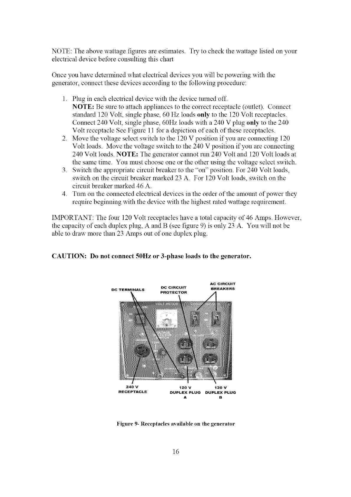
240 V t20 V _20 V
RECEPTACLE DUPLEX PLUG DUPLEX PLUG
A B
Figure 9- Receptacles available on the generator
16
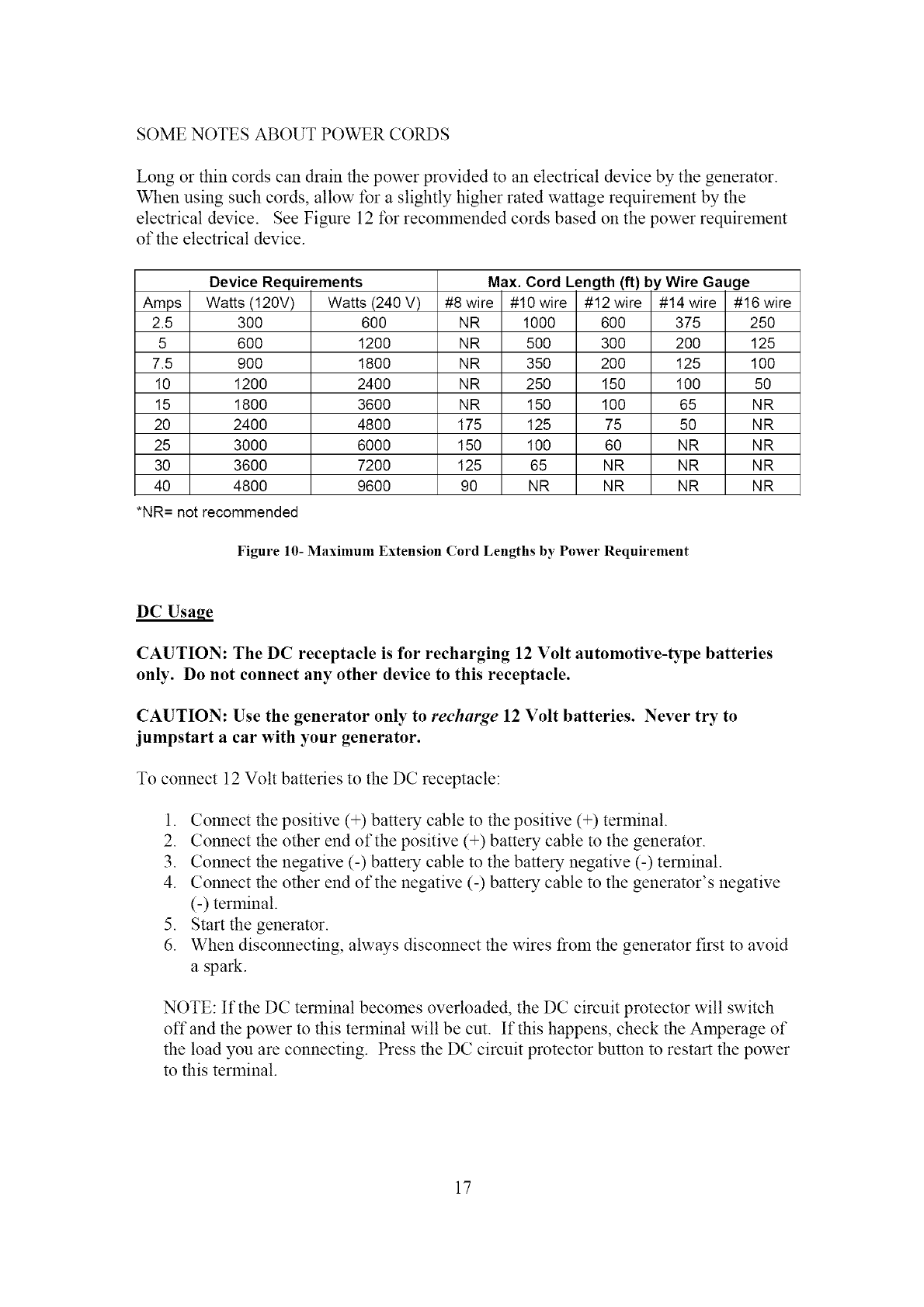
SOME NOTES ABOUT POWER CORDS
Long or thin cords can drain the power provided to an electrical device by the generator.
When using such cords, allow tbr a slightly higher rated wattage requirement by the
electrical device. See Figure 12 ff_r recommended cords based on the power requirement
of the electrical device.
Device Requirements
Amps Watts (t20V)
2.5 300
5 600
7.5 900
10 1200
15 1800
20 2400
25 3000
30 3600
40 4800
*NR= not recommended
Max. Cord Length (it)
Watts(240 V) #8 wire
600 NR
1200 NR
1800 NR
2400 NR
3600 NR
4800 175
6000 150
7200 125
9600 90
#10 wire #12 wire
1000 600
500 300
350 200
250 150
150 100
125 75
100 60
65 NR
NR NR
by Wire Gauge
#14 wire #16 wire
375 250
200 125
125 100
100 50
65 NR
50 NR
NR NR
NR NR
NR NR
Figure 10- Maximum Extension (ord Lengths by Power Requirement
DCUsage
CAUTION: The DC receptacle is for recharging 12 Volt automotive-type batteries
only. Do not connect any other device to this receptacle.
CAUTION: Use the generator only to recharge 12 Volt batteries. Never try to
jumpstart a car with your generator.
To connect 12 Volt batteries to the DC receptacle:
1. Connect the positive (+) battery cable to the positive (+) terminal.
2. Connect the other end of the positive (+) battery cable to the generator.
3. Connect the negative (-) battery cable to the battery negative (-) terminal.
4. Connect the other end of the negative (-) battery cable to the generator's negative
(-) terminal.
5. Start the generator.
6. When disconnecting, always disconnect the wires from the generator first to avoid
a spark.
NOTE: If the DC terminal becomes overloaded, the DC circuit protector will switch
offand the power to this terminal will be cut. If this happens, check the Amperage of
the load you are connecting. Press the DC circuit protector button to restart the power
to this terminal.
17
DANGER: Storage batteries emit highly explosive hydrogen gas when charged.
Batteries also contain acid, which can cause severe chemical burns.
•Do not allow open flames or cigarettes nearby for several minutes after
charging a battery.
•Always wear protective goggles and rubber gloves when charging a battery.
>If battery acid gets on your skin, flush with water.
If battery acid gets in your eyes, flush with water and call a physician
immediately.
If battery acid is swallowed, drink large quantities of milk and call a
physician immediately.
STOPPING THE GENERATOR
To stop the generator:
1. Turn off; then unplug all connected electrical devices.
2. Switch the circuit breaker to the "oft" position.
3. Allow the generator to run for several more minutes with no electrical devices
connected. This helps stabilize the temperature of the generator.
4. Set the engine switch to the "off' position.
5. Turn the fuel valve to the "off' position.
AWARNING: Allow the generator to cool for several minutes before touching
areas that become hot during use.
CAUTION: Allowing gas to sit in the generator tank for long periods of time
without use can make it difficult to start the generator in the future. Never store
generator for extended periods of time with fuel in the tank.
18
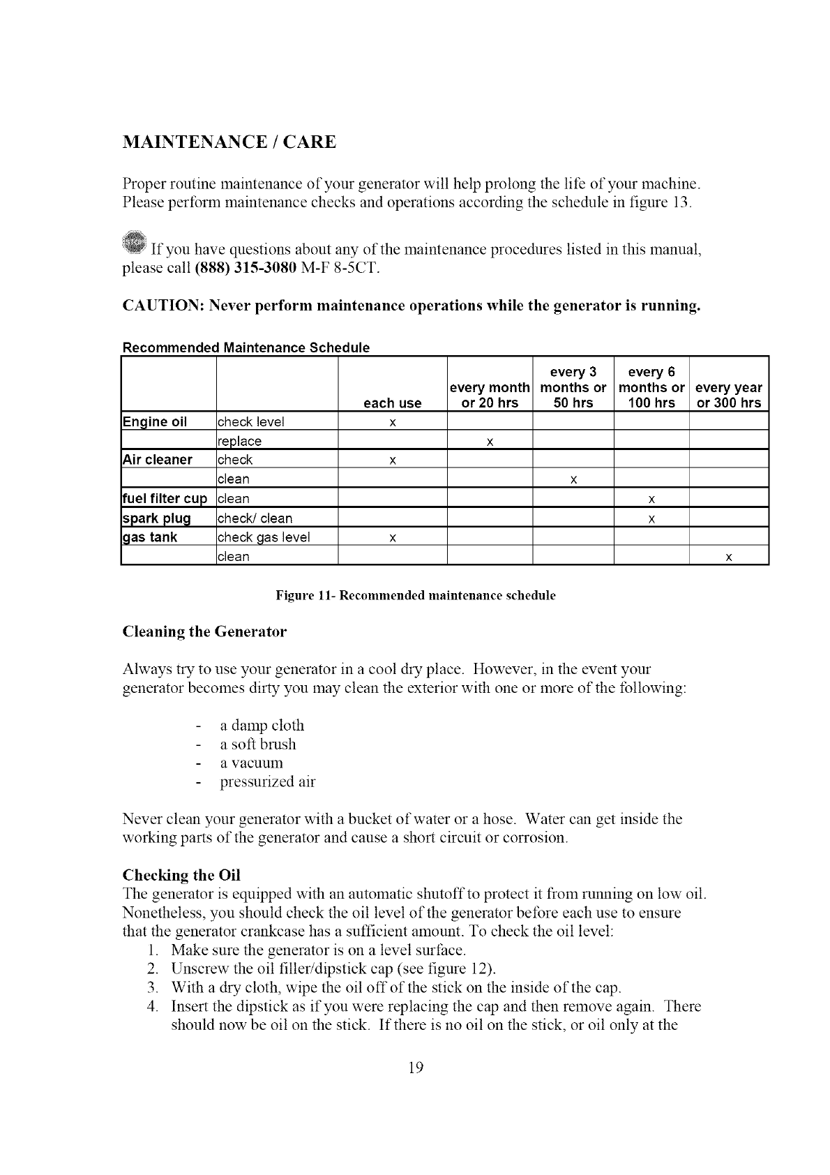
MAINTENANCE/CARE
Proper routine maiutenance of your generator will help prolong the life of your machine.
Please perform maintenance checks and operations according the schedule in figure 13.
If you have questions about any of the maintenance procedures listed in this manual,
please call (888) 315-3080 M-F 8-5CT.
CAUTION: Never perform maintenance operations while the generator is running.
Recommended Maintenance Schedule
every 3 every 6
every month months or months or every year
each use or 20 hrs 50 hrs 100 hrs or 300 hrs
Engine oil :heck level x
replace x
Air cleaner :heck x
:lean x
fuel filter cup :lean x
spark plu_t :heck/clean x
gas tank :heck gas level x
:lean x
Figure 11- Recommended maintenance schedule
Cleaning the Generator
Always try to use your generator in a cool dry place. However, in the event your
generator becomes dirty you may clean the exterior with one or more of the following:
a damp cloth
a soft brush
a vacuulrl
pressurized air
Never clean your generator with a bucket of water or a hose. Water can get inside the
worldng parts of the generator and cause a short circuit or corrosion.
Checking the Oil
The generator is equipped with an automatic shutoffto protect it froln running on low oil.
Nonetheless, you should check the oil level of the generator before each use to ensure
that the generator crankcase has a sufficient alnount. To check the oil level:
1. Make sure the generator is on a level surface.
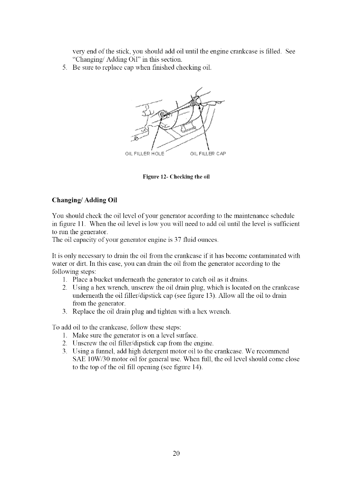
2. Unscrew the oil filler/dipstick cap (see figure 12).
3. With a dry cloth, wipe the oil offofthe stick on the inside of the cap.
4. Insert the dipstick as if you were replacing the cap and then remove again. There
should now be oil on the stick. If there is no oil on the stick, or oil only at the
19
very end of the stick, you should add oil until the engine crankcase is filled. See
"Changing/Adding Oil" in this section.
5. Be sure to replace cap when finished checking oil.
OR. FiLLEiR HOU!!!
Figure 12- Checking the oil
Changing/Adding Oil
You should check the oil level of your generator according to the maintenance schedule
in figure 11. When the oil level is low you will need to add oil until the level is sufficient
to run the generator.
The oil capacity of your generator engine is 37 fluid ounces.
It is only necessary to &ain the oil from the crankcase if it has become contaminated with
water or dirt. In this case, you can drain the oil t}om the generator according to the
tbllowing steps:
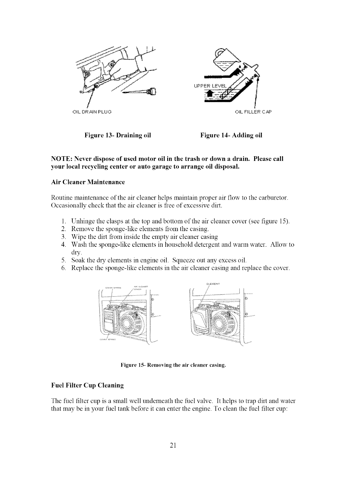
1. Place a bucket underneath the generator to catch oil as it drains.
2. Using a hex wrench, unscrew the oil drain plug, which is located on the crankcase
underneath the oil filler/dipstick cap (see figure 13). Allow all the oil to &ain
from the generator.
3. Replace the oil drain plug and tighten with a hex wrench.
To add oil to the crankcase, tbllow these steps:
1. Make sure the generator is on a level surface.
2. Unscrew the oil filler/dipstick cap t}Oln the engine.
3. Using a funnel, add high detergent motor oil to the crankcase. We recommend
SAE 10W/30 motor oil for general use. When full, the oil level should come close
to the top of the oil fill opening (see figure 14).
20
OIL DR _r',iPLU'2J O_L F_LLER C_P
Figure 13- Draining oil Figure 14- Adding oil
NOTE: Never dispose of used motor oil in the trash or down a drain. Please call
your local recycling center or auto garage to arrange oil disposal.
Air Cleaner Maintenance
Routine maintenance of the air cleaner helps maintain proper air flow to the carburetor.
Occasionally check that the air cleaner is l}ee of excessive dirt.
1. Unhinge the clasps at the top and bottom of the air cleaner cover (see figure 15).
2. Remove the sponge-like elements l}Oln the casing.
3. Wipe the dirt t}Oln inside the empty air cleaner casing
4. Wash the sponge-like elements in household detergent and warm water. Allow to
dry.
5. Soak the dry elements in engine oil. Squeeze out any excess oil.
6. Replace the sponge-like elements in the air cleaner casing and replace the cover.
'--zi ; :: ;::::: 7: ::A i
Figure 15- Removing the air cleaner casing.
Fuel Filter Cup Cleaning
The fuel filter cup is a small well underneath the fuel valve. It helps to trap dirt and water
that may be in your fuel tank belbre it can enter the engine. To clean the fuel filter cup:
21
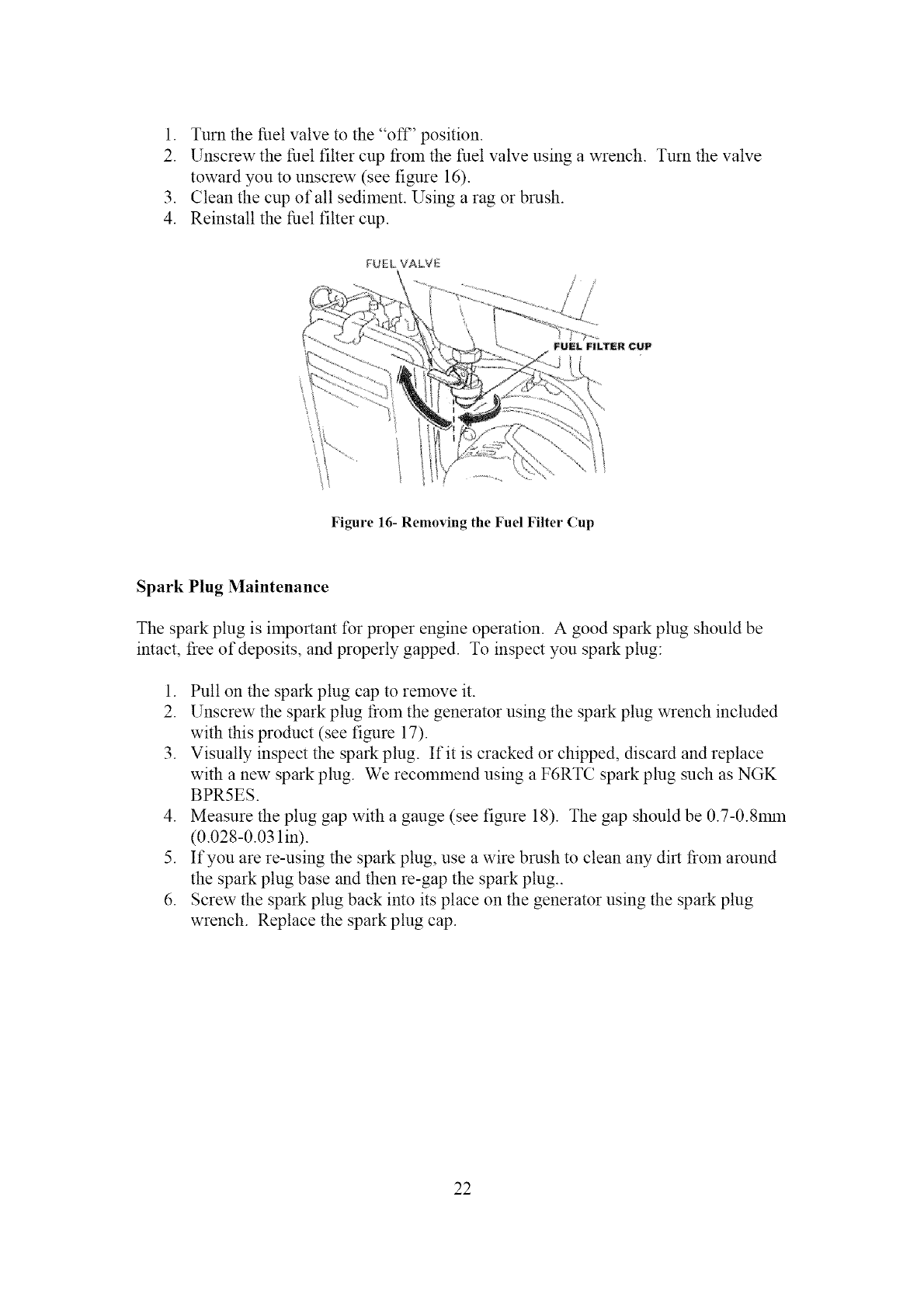
1. Turnthefuelvalveto the"of£' position.
2. Unscrewthefuelfilter cupfrolntilefuelvalveusingawrench.Turnthevalve
towardyouto unscrew(seefigure16).
3. Cleanthecupof all sediment.Usingaragor brush.
4. Reinstallthefuelfilter cup.
FU;EL VALVE
Figure 16- Removing the Fuel Filter (up
Spark Plug Maintenance
The spark plug is important for proper engine operation. A good spark plug should be
intact, t_ee of deposits, and properly gapped. To inspect you spark plug:
1. Pull on the spark plug cap to remove it.
2. Unscrew the spark plug from the generator using the spark plug wrench included
with this product (see figure 17).
3. Visually inspect the spark plug. If it is cracked or chipped, discard and replace
with a new spark plug. We recommend using a F6RTC spark plug such as NGK
BPR5ES.
4. Measure the plug gap with a gauge (see figure 18). The gap should be 0.7-0.8rain
(0.028 -0.031 in).
5. If you are re-using the spark plug, use a wire brush to clean any dirt t?om around
the spark plug base and then re-gap the spark plug..
6. Screw the spark plug back into its place on the generator using the spark plug
wrench. Replace the spark plug cap.
22
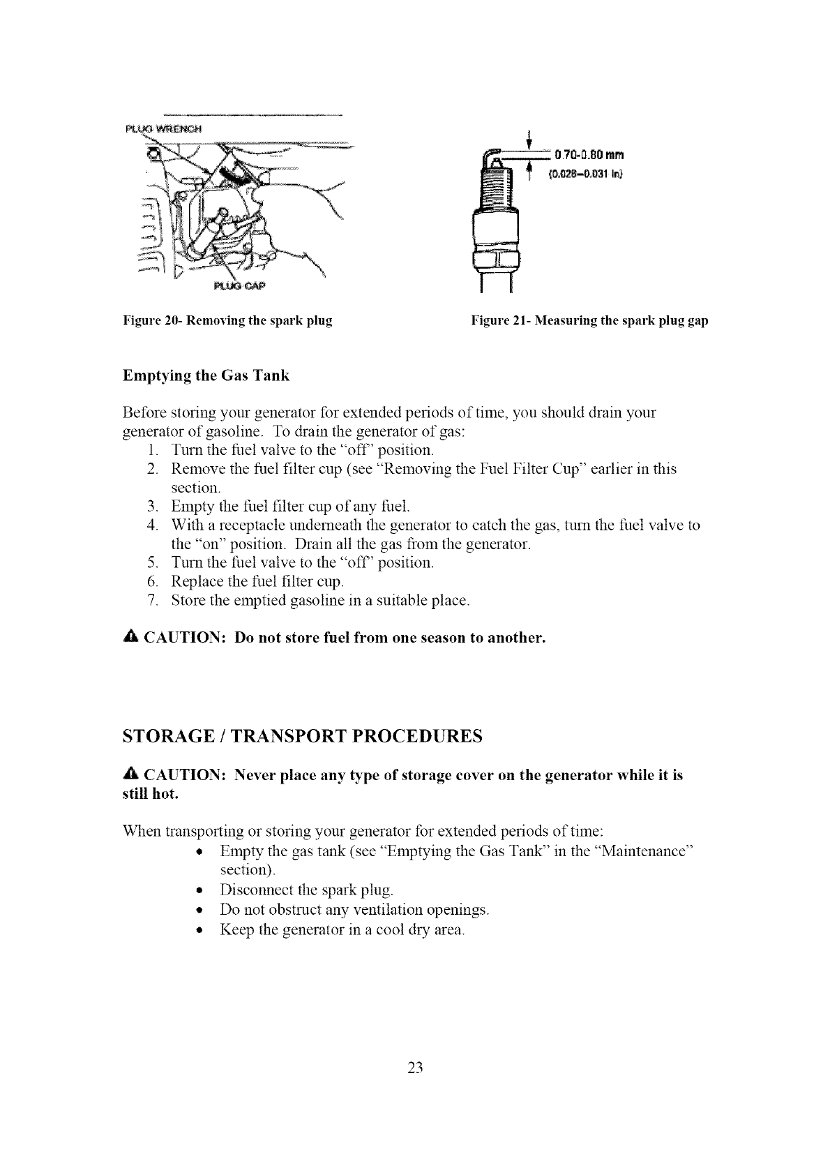
Figure 20- Removing the spark plug Figure 21- Measuring the spark plug gap
Emptying the Gas Tank
Before storing your generator tbr extended periods of time, you should drain your
generator of gasoline. To &ain the generator of gas:
1. Turn the fuel valve to the "ofF' position.
2. Relnove the fuel filter cup (see "Removing the Fuel Filter Cup" earlier in this
section.
3. Empty the fuel filter cup of any fuel.
4. With a receptacle underneath the generator to catch the gas, turn the fuel valve to
the "on" position. Drain all the gas t_Oln the generator.
5. Turn the fuel valve to the "ofF' position.
6. Replace the fuel filter cup.
7. Store the emptied gasoline in a suitable place.
A CAUTION: Do not store fuel from one season to another.
STORAGE /TRANSPORT PROCEDURES
_fiLCAUTION: Never place any type of storage cover on the generator while it is
still hot.
When transporting or storing your generator for extended periods of time:
• Empty the gas tank (see "Emptying the Gas TAN<" in the "Maintenance"
section).
• Disconnect the spark plug.
• Do not obstruct any ventilation openings.
• Keep the generator in a cool dry area.
23
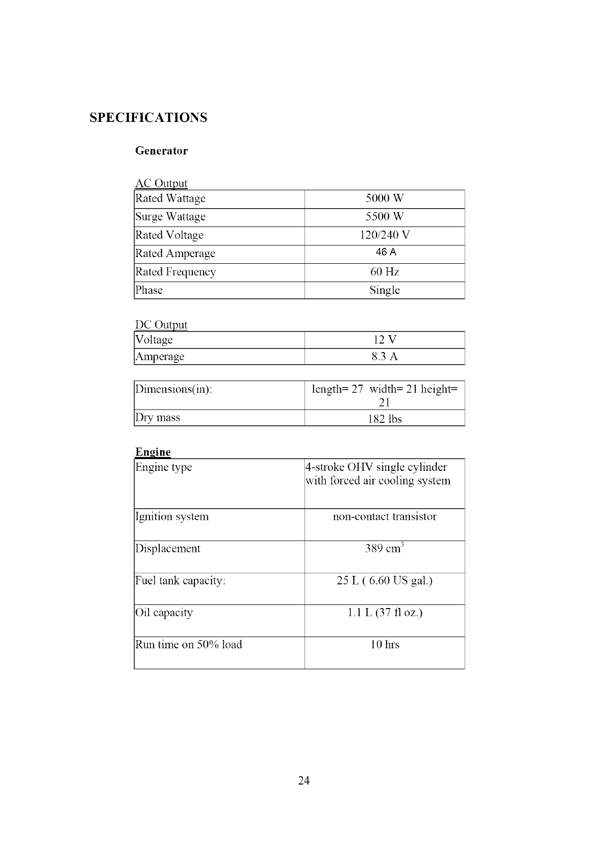
SPECIFICATIONS
Generator
AC Output
Rated Wattage 5000 W
Surge Wattage 5500 W
Rated Voltage 120/240 V
Rated Amperage 46 A
Rated Frequency 60 Hz
Phase Single
DC Output
_g 12V
e 8.3 A
Dimensions(in): length = 27 width = 21 height =
21
Dry mass 182 lbs
Engine
Engine type 4-stroke OHV single cylinder
with forced air cooling system
[gnition system non-contact transistor
Displacement 389 cm 3
Fuel tank capacity: 25 L ( 6.60 US gal.)
Oil capacity 1.1 L (37 fl oz.)
Run time on 50% load 10 hrs
24
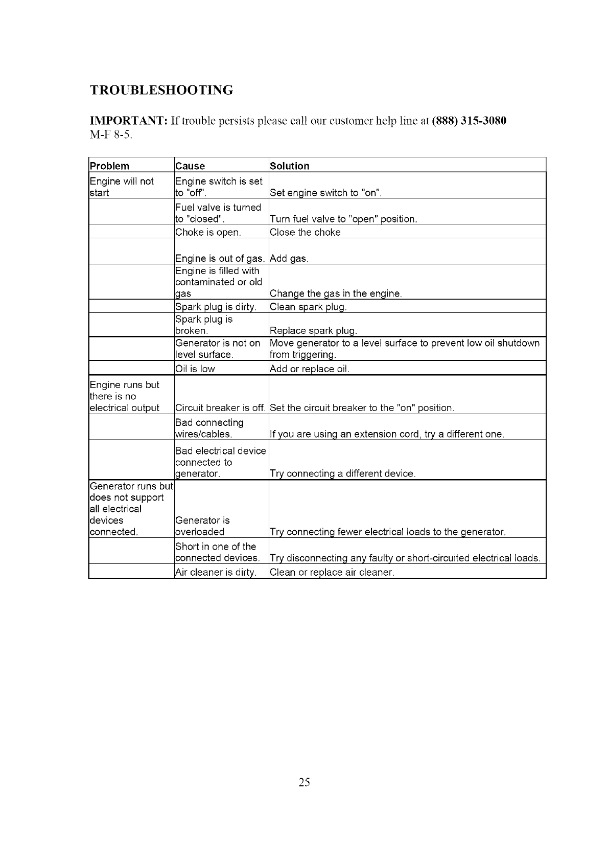
TROUBLESHOOTING
IMPORTANT: If trouble persists please call our customer help line at (888) 315-3080
M-F 8-5.
Problem
Engine will not
start
Engine runs but
there is no
electrical output
Generator runs but
does not support
all electrical
devices
connected.
3ause
Engine switch is set
:O "Off",
--uel valve is turned
:o "closed".
Choke is open.
Engine is out of gas.
Engine is filled with
:ontaminated or old
_las
Spark plug is dirty.
Spark plug is
3roken.
3enerator is not on
evel surface.
9il is low
Circuit breaker is off.
Bad connecting
Nires/cables.
Bad electrical device
:onnected to
_enerator.
3enerator is
3verloaded
Short in one of the
:onnected devices.
_,ir cleaner is dirty.
Solution
Set engine switch to "on".
]urn fuel valve to "open" position.
Close the choke
_,dd gas.
Change the gas in the engine.
Clean spark plug.
Replace spark plug.
Move generator to a level surface to prevent low oil shutdown
from triggering.
_,dd or replace oil.
Set the circuit breaker to the "on" position.
If you are using an extension cord, try a different one.
]'ry connecting a different device.
Try connecting fewer electrical loads to the generator.
Try disconnecting any faulty or short-circuited electrical loads.
Clean or replace air cleaner.
25
©
>
>
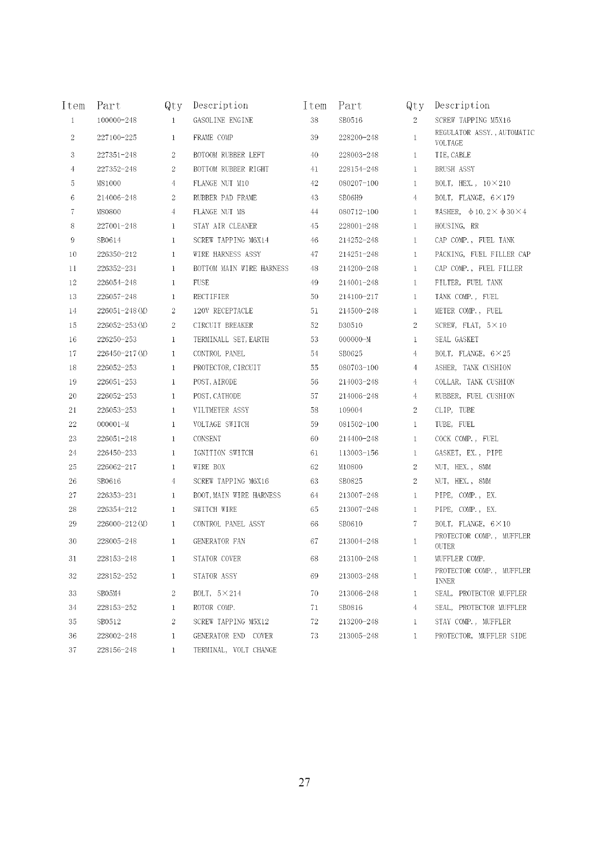
Item
1
2
3
4
5
6
7
8
9
10
11
12
13
14
15
16
17
18
19
20
21
22
2',3
24
25
26
27
28
29
',30
',31
',32
3',3
34
35
36
37
Par_
lOOOOO 248
227100 225
227351 248
227:352 248
M810OO
214006 248
M80800
227001 248
SBO614
226350 212
226352 231
226054 248
226057 248
226051 248(M)
226052 253(M)
226250 253
226450 217(M)
226052 253
226051 253
226052 253
226053 253
O0O0Ol M
226051 248
228450 233
228082 217
SBO616
226353 231
226354 212
226000 212(M)
228005 248
228153 248
228152 252
SBO5M4
228153 252
SB0512
228002 248
228156 248
Qty Description Item Part
1 GASOLINE ENGINE :38 SB0516
1 FRAME COMP :39 228200 248
2 BOTOOM RUBBER LEFT 40 228003 248
2 BOTTOM RUBBER RIGHT 41 228154 248
4 FLANGE \TT MIO 42 080207 100
2 RUBBER PAD FRAME 43 SBO6H9
4 FLANGE NUT MS 44 080712 100
1 STAY AIR CLEANER 45 228001 248
1 SCREW TAPPING M6K14 46 214252 248
1 WIRE HARNESS ASSY 47 214251 248
1 BOTTOM MAIN WIRE HARNESS 48 214200 248
1 FUSE 49 214001 248
1 RECTIFIER 50 214100 217
2 12OV RECEPTACLE 51 214500 248
2 CIRCUIT BREAKER 52 D30510
1 TERMI\ALL SET, EARTH 53 000000 M
1 CONTROL PANEL 54 SB0625
1 PROTECTOR, CIRCUIT 55 080703 100
1 POST, AIRODE 56 214003 248
1 POST, CATHODE 57 214006 248
1 VILTMETER ASSY 58 109004
1 VOLTAGE SWITCH 59 081502 100
1 CONSENT 60 214400 248
1IGNITION SWITCH 61 113003 156
1 WIRE BOX 62 MlO800
4 SCREW TAPPING M6X16 63 SB0825
1 BOOT, MAIN WIRE HARNESS 64 213007 248
I SWITCH WIRE 65 213007 248
1 CONTROL PANEL ASSY 66 SB0610
1 GENERATOR FAN 67 213004 248
1 8TATOR COVER 68 213100 248
1 STATOR ASSY 69 213003 248
2 BOLT, 5X214 70 213006 248
1 ROTOR COMP. 71 SB0816
2SCREW TAPPING MSX12 72 213200 248
1 GENERATOR END COVER 73 213005 248
1 TERMI\AL, VOLT CHANGE
Qty Description
2 SCREW TAPPING M5X16
REGULATORASSY.,AUTOMATIC
1VOLTAGE
1 TIE, CABLE
1BRUSH ASSY
1 BOLT, HEN., 10X210
4 BOLT, FLANGE, 6X 179
1 MASHER, <_10.2 X <_30 X 4
1 HOUSINg, RR
1 CAP COMP., FUEL TANK
1 PACKING, FUEL FILLER CAP
1 CAP COMP., FUEL FILLER
1 FILTER, FUEL TANK
1 TANK COMP., FUEL
1 METER COMP., FUEL
2 SCREW, FLAT, 5X 10
1 SEAL GASKET
4 BOLT, FLANGE, 6X25
4 ASHER, TANK CUSHION
4 COLLAR,TANKCUSHION
4 RUBBER, FUEL CUSHION
2 CLIP, TUBE
1 TUBE, FUEL
1COCK COMP., FUEL
1 GASKET, EX., PIPE
2 hiT, HEN., 8_Bi
2 \17, HEX., 8_BI
1 PIPE, COMP., EX.
1 PIPE, COMP., EX.
7 BOLT, FLANGE, 6X 10
PROTECTOR COMP. , MUFFLER
1OUTER
1 _9JFFLER COMP.
PROTECTOR COMP., MUFFLER
1INNER
1SEAL, PROTECTOR MUFFLER
4 SEAL, PROTECTOR MUFFLER
1 STAY CO_IP., _KFFLER
1 PROTECTOR, MUFFLER SIDE
27

NOTES:
29
LIMITED WARRANTYFORPOWERPROTM GENERATORS FROM WEN POWER TM
Remember to save your receipt and to accurately f!ll out and mail your product
registration card. You must provide proof ojpurchasejbr all warranty work.
Power Pro TM generators are warramed to be t}ee from defects in materials and
wofl¢manship for a period of one (1) year froln date of original purchase. Generators
used for Colmnercial or Rental use have a warranty period of 90 days frolFl date of
original purchase. Keep purchase receipt and mail in the product registration card for
proof o f purchase.
Power Pro TM by WEN Power TM will repair or replace, at its discretion, a W part that is
proven to be detective in materials or workmanship under normal use during the one (1)
year warranty period. Warranty repairs or replacements will be made without charge for
parts or labor. Parts replaced during warranty repairs will be considered as part of the
original product and will have the same warranty period as the original product.
To exercise the warranty, DO NOT RETURN TO RETAILER. Instead, call the toll
t_ee Customer Service number: (888) 315-3080 and you will be instructed on where to
take the generator tbr warranty service. Take the generator and proof of purchase (your
receipt) to the repair facility recommended by the Customer Service Representative.
The warranty does not extend to generators damaged or affected by fuel contamination,
accidents, neglect, misuse, unauthorized alterations, use in an application for which the
product was not designed and any other modifications or abuse.
Power Pro TM by WEN Power TM is not liable for any indirect, incidental or consequential
damages t_Oln the sale or use of this product. Any implied warranties are limited to one
(1) year as stated in this written limited warranty. Some states do not allow the exclusion
or limitation of incidental or consequential damages. Some states do not allow limitation
on the length of an implied warranty. This warranty gives you specific legal rights, and
you may have other rights that vary t}om state to state.
Power Pro by Wen Power TM. Elgin, IL 60123. www.wenproduets.eom.
3O
