Powertech Co R9P125 Green Power Surge Protector User Manual Green Powerlink V1
Powertech Industrial Co Ltd Green Power Surge Protector Green Powerlink V1
User Manual

User Manual
All Versions
© Copyright 2010
The information contained herein is subject to change without notice.
The information contained herein is subject to change without notice.
This document contains proprietary information, which is protected by copyright.
No part of this document may be photocopied, reproduced, or translated
into another language without the prior written consent.
April 2010
R9P014 / R9P125 / R9P602
GREEN POWERLINK
Smart Energy Monitoring &
Surge Protecting Solution

INTRODUCTION----------------------------------------------------- 2
FEATURES AND FUNCTIONS---------------------------------------- 3
INSTALLATION------------------------------------------------------ 8
Wireless Setup Range-------------------------------------------- 8
Install Wall Tap Surge Protector---------------------------------- 8
Install Strip Surge Protector------------------------------------- 8
INITIAL SETUP------------------------------------------------------ 9
Install Battery in Energy Monitor--------------------------------- 9
Use an AC/DC Adapter (Optional)--------------------------------- 10
Wall Mount the Energy Monitor-----------------------------------10
Perform Energy Monitor Initial Setup-----------------------------10
Date & Time Setup----------------------------------------------------- 10
Currency Setup---------------------------------------------------------12
Electricity Rate Setup---------------------------------------------------12
Carbon Emission Setup-------------------------------------------------13
Audible Alarm Setup----------------------------------------------------14
OPERATION--------------------------------------------------------- 14
Energy Monitor Display Mode------------------------------------ 14
Channel Mode (Default page)------------------------------------------ 15
Energy Mode----------------------------------------------------------- 16
Cost Mode-------------------------------------------------------------- 17
CO2 Mode-------------------------------------------------------------- 18
Event Mode-------------------------------------------------------------18
Surge Alert Mode-------------------------------------------------------20
Advance Setup Instruction------------------------------------------ 23
Delete Event Data Setup------------------------------------------23
Delete Surge Event Data Setup----------------------------------- 24
Delete History Data Setup---------------------------------------- 24
Exit the Setup Page---------------------------------------------- 25
Add Channels to the Energy Monitor by Learning------------------ 25
Reset the Energy Monitor to Factory Default----------------------- 26
Thank you for purchasing the GREEN POWERLINK Energy Saving Solution, an
innovative product which is designed to manage home electricity usage efficiently
and reduce home electricity bill.
In an effort to reduce your electricity bills, why not first check out what appliance
uses most energy in your home.
The New GREEN POWERLINK Energy Monitor allows you to take control of home
electricity usage while saving you money in the process.
With GREEN POWERLINK, you can see how much electricity you are using and
with greater awareness you’ll become more energy efficient.
Fully educated with the critical energy information, you are naturally motivated to
adopt new energy saving habits and reduce harmful carbon emission for our
environment.
Besides energy conservation, the GREEN POWERLINK surge protectors are also
equipped with fireproof Surge MOV technology and this ensures your home
appliances are well protected and free of fire hazard during catastrophic surge
events.
The GREEN POWERLINK is the total solution for green inspiration, energy
conservation, and surge protection for your everyday life.
G
REEN POWERLINK Manual All Versions V1.
0
1
G
REEN POWERLINK Manual All Versions V1.0 2
G
REEN P
O
W
ERLINK Manual All
V
e
r
s
ions V1.
0
3
G
REEN PO
W
ERLINK Manual All
V
e
r
s
ions V1.
0
4
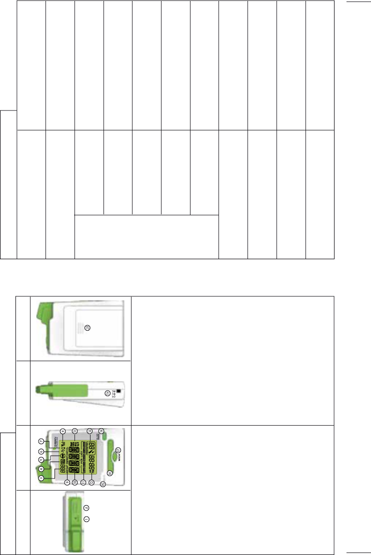
Smart Energy Monitor Features
Top View Front View Side View Back View
1. RESET Key: restore factory default
2. LEARNING Key: add new channel
3. Channel indicator
4. Indicates ON/OFF status of
energy saver outlets
5. Power failure event indicator
6. Indicates audible alarm is ON
7. Energy monitor low battery indicator
8. Wireless signal strength indicator
9. Indicates what display mode the
monitor displays: INSTANT ENERGY /
ENERGY / COST/ CO2
10. Data display
11. Projected and historical data display
12. Clock display
13. Measurement units for display modes
14. Surge event counter display
15. Embedded alarm speaker
16. Cursor selector Key
17. MODE Key: switch to different
display mode
18. ON&OFF Key: control energy saver outlet
SET Key: confirmation button
19. AC/DC power adaptor input (Optional)
20. Battery compartment
Smart Energy Monitor Specification
Radio Frequency 915MHz
Wireless Range
LCD Dimension
Replaceable Battery
DC Input
Operating Temperature
915MHz
Up to 100 Ft
Yes
Yes
Up to 9 Channels
Yes
Yes
45mm x 55mm
AA Battery X4
9V / 1000 mA
5℃~45℃ at 85% relative humidity
Control Energy Saver
outlets ON/OFF
Audible Alarm Alert
Channels control
and monitoring
Learning Function
Wall Mountable
Functions
R9P014 Series
GREEN
P
OWERLINK Manual All
V
e
r
sions V1.
0
5GREEN
P
OWERLINK Manual All
V
e
r
sions V1.0 6
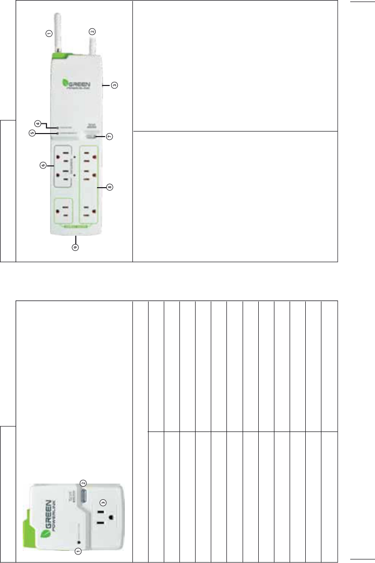
Strip Type Surge Protector Features
1. Wireless Antenna
- External antenna for better reception
2. AC Power Cord
3. Overload Resettable Circuit Breaker
- Protects against current overload
at 15 Amps
- Press to reset the circuit breaker
4. Surge Protection LED Indicator
- The lighted green LED indicates the
surge protection is working
5. Grounded Fault LED Indicator
- The Red LED light only illuminates to
indicate the power outlets are not
properly grounded
6. 2 “Always On” outlets
- Provide continuous power for
connected devices
7. Manual ON/OFF & LEARNING Key
-Manual ON/OFF Mode: press the
Manual ON/OFF Key to turn ON/OFF
the energy saver outlets
-Learning Mode: press the LEARNING
key to pair up the surge protector with
the energy monitor
8. 4 “Energy Saver” outlets
-The Energy Saver outlets can be
wirelessly turned ON/OFF by the smart
energy monitor to eliminate stand-by
power waste
9. Secondary Protection (Optional)
-Phone / Data line or Coax protection
Wall Tap Surge Protector Features
Wall Tap Surge Protector Specification
1. Surge Protection LED Indicator
- The lighted green LED indicates the surge protection
is working
2. Manual ON/OFF & LEARNING Key
- Manual ON/OFF Mode: press the Manual ON/OFF Key
to turn ON/OFF the AC outlet
- Learning Mode: press the LEARNING key to pair up the
surge protector with the energy monitor
3. AC Outlet
- Monitor individual home appliance electricity usage
Radio Frequency
Wireless Range
Energy Saver Outlet
AC Rating
Surge Suppression Rating
Clamping Voltage
Surge Protected LED Indicator
Energy Saver Outlet Power ON LED Indicator
Manual ON/OFF , LEARNING Key
Stand-by Power
Operating Temperature
Storage Temperature
915MHz
Up to 100 Ft
1
15A / 125V / 1875W
540J
500V
Green
Green
yes
<1 W
5℃~45℃ at 85% relative humidity
-5℃~60℃ at 85% relative humidity
R9P125 Series R9P602 Series

G
REEN POWERLINK Manual All Versions V1.
0
7
G
REEN POWERLINK Manual All Versions V1.0 8
Strip Type Surge Protector Specification
Radio Frequency
Wireless Range
Always On Outlets
Energy Saver Outlets
AC Rating
Surge Suppression Rating
Clamping Voltage
Surge Protected LED Indicator
Grounded Fault LED Indicator
Always On LED Indicator
External Antenna
Manual ON/OFF , LEARNING Key
Stand-by Power
Operating Temperature
Storage Temperature
915MHz
Up to 100 Ft
2
4
15A / 125V / 1875W
1080J
400V
Green
Red
Green
Yes
Yes
<1 W
5ƨ~45ƨ at 85% relative humidity
-5ƨ~60ƨ at 85% relative humidity
Wireless Setup Range
The energy monitor and surge protector communicate in two-way. To ensure
energy monitor and surge protector communicate with no interruption, please
locate and setup both devices within 100 Ft of range.
Install Wall Tap Surge Protector
The single outlet wall tap surge protector allows the user to track electricity
consumption of individual home appliance and protect it against surge and voltage
spikes.
1. Plug in the wall tap surge protector to a powered 125V AC outlet.
2. Plug in the appliance into the wall tap surge protector outlet.
3. The outlet power can be manually turned ON/OFF by pressing the “Manual
ON/OFF” button on the wall tap surge protector. You may also turn ON/OFF the
outlet power remotely by using the energy monitor (see the operating
instruction – channel mode).
Note: The outlet on the surge protector is default at power off status.
Install Strip Surge Protector
The strip type surge protector allows the user to track electricity consumption of
group home appliances by area and protect them against surge and voltage spike.
1. Connect home appliances to the “ENERGY SAVER” outlets. These outlets are for
appliances which do not need to be on all the time and can be completely turned
off when not in use to eliminate stand-by power waste. The “ENERGY SAVER”
outlets can be controlled ON/OFF by remote energy monitor (see the operating
instruction – channel mode).
2. Connect home devices to the “ALWAYS ON” outlets. These outlets are not
switchable and provide continuous power for appliances which always need to
stay on at all time.

GREEN POWERLINK Manual All Versions V1.
0
9
G
REEN POWERLINK Manual All Versions V1.
0
10
3. Plug in the AC power cord of the strip surge protector to a powered 125V AC
outlet.
4. The “ENERGY SAVER” outlets power can be manually turned ON/OFF by
pressing the “Manual ON/OFF” button on the strip surge protector.
Note: The ENERGY SAVER outlets on the surge protector are default at power off
status.
Wall Mount the Strip Surge Protector
1. There are mounting holes on the back of the strip surge protector for wall or
base board mounting.
2. Install screws (not included) on wall or baseboard surface (leaving at least 1/4
inch of the screw exposed).
3. Place and secure the Surge Protector on mounted screws.
Install Battery in Energy Monitor
Open the battery compartment on the back of the energy monitor and install 4 x
AA 1.5V alkaline batteries with right polarity.
Warning: Reversing the polarity may damage the product.
Once batteries are installed, the energy monitor will turn on and enter initial setup
mode. Please proceed and refer to the next instruction for initial setup.
Note:
Batteries are not included in the product kit.
Please do not mix and match different types / new & old batteries in use with the
energy monitor.
Use an AC/DC Adapter (Optional)
The energy monitor can operate with a 9V AC/DC adapter, which can be purchased
separately.
When the AC/DC adaptor is used in conjunction with batteries installed, the energy
monitor will be powered by the AC/DC adaptor to save batteries life in the energy
monitor.
Wall Mount the Energy Monitor
1. Select a spot within the wireless range to mount the supplied wall bracket for
the energy monitor.
2. The ideal locations for the energy monitor wall mount are entrance of a room or
location where the energy monitor can be easily seem and accessed.
3. Use adhesive tape or supplied screws to securely attach the supplied wall
bracket to a wall.
Perform Energy Monitor Initial Setup
Please perform the following initial setup steps for first time operation
1. Date & Time Setup
2. Currency Setup
3. Electricity Rate Setup
4. Carbon Emission Setup
5. Audible Alarm Setup
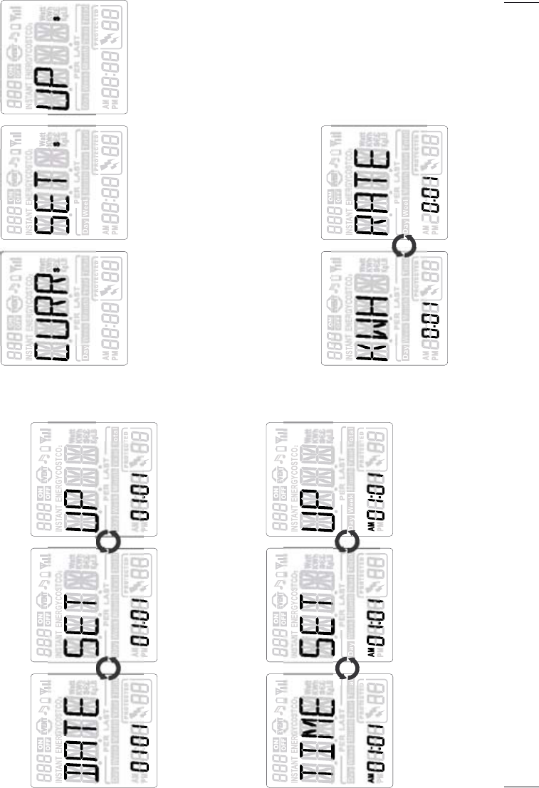
Date & Time Setup
G
REEN POWERLINK Manual All Versions V1.0
11 GREEN POWERLINK Manual All Versions V1.0 12
1. In year setup page, “YEARƖSETƖUP” displays in looping.
2. The year value blinks. Use the arrow key to change the year value.
3. Press the SET button to proceed to Date setup page.
1. In date setup page, “DATEƖSETƖUP” displays in looping.
2. The month value blinks first. Use the arrow key to change the month value first
then press the SET button to proceed to day setup.
3. The day value blinks. Use the arrow key to change the day value. Press the SET
button to proceed to Time setup page.
Currency Setup
1. In Currency setup page, “CURRƖSETƖUP” displays in looping.
2. The $ symbol blinks first. Use the arrow key to select currency symbol
in $ /€ /£.
3. Press the SET button to proceed to Electricity Utility Rate setup page.
Electricity Rate Setup
There are more than 4,000 electric utilities across the US and Canada. In the event
your local utility uses a tariff calculation other than flat electricity rate, please key
in the average rate that most nearly resembles your utility’s tariff schedule.
G
REEN P
O
WERLINK M
a
n
ua
l All V
e
r
s
i
o
n
s
V1.
0
13
G
REEN P
O
WERLINK M
a
n
ua
l All V
e
r
s
i
o
n
s
V1.
0
14
1. In Electricity Rate setup page, “KWHƖRATE” in looping display represents cost
of KWH of your electricity rate.
2. The rate value blinks. Use the arrow key to change the rate value.
3. Press the SET button to proceed to Carbon Emission setup page.
Carbon Emission Setup
Carbon dioxide is emitted in the process of producing electricity by burning coal &
fossil fuel. This is usually referred to CO2 footprint or carbon emission, which in
turn has contributed global warming and caused abnormal weather.
The average carbon emission rate is 0.43Kg (0.95lbs) of carbon emission for every
1 KWH of electricity produced. This can be changed depending upon your local
electric utility. Please contact your local utility for carbon emission rate.
1. In Carbon Emission Setup page, “CO2ƖSETƖUP” displays in looping.
2. The Kg symbol blinks first. Use the arrow key to select the weight symbol in Kg
or LB. Then press the SET button to proceed to carbon emission rate setup.
3. The carbon emission rate blinks. Use the arrow key to change the value. Press
the SET button to proceed to Audible Alarm setup page
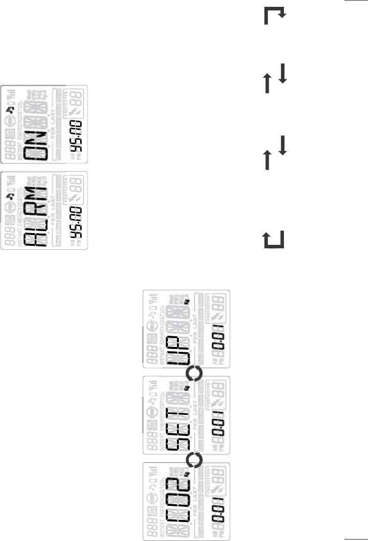
Audible Alarm Setup
1. In Audible Alarm setup page, “ALRMƖON” displays in looping.
2. The YES [YS]option blinks first. Use the arrow key to select Yes or NO to enable
or disable audible alarm for surge and event alert.
3. Press the SET button finish the initial setup and the page will proceed to default
Channel mode automatically.
Energy Monitor Display Mode
The energy monitor provides 6 types of display modes. Press the MODE button to
scroll thru different display modes.
Channel Mode!Energy Mode!Cost Mode
Surge Alert Mode!!!!!!!!!!Event Mode!!!!!!!!!!CO2 Mode
GREEN POWERLINK Manual All Versions V1.
0
15
G
REEN POWERLINK Manual All Versions V1.
0
16
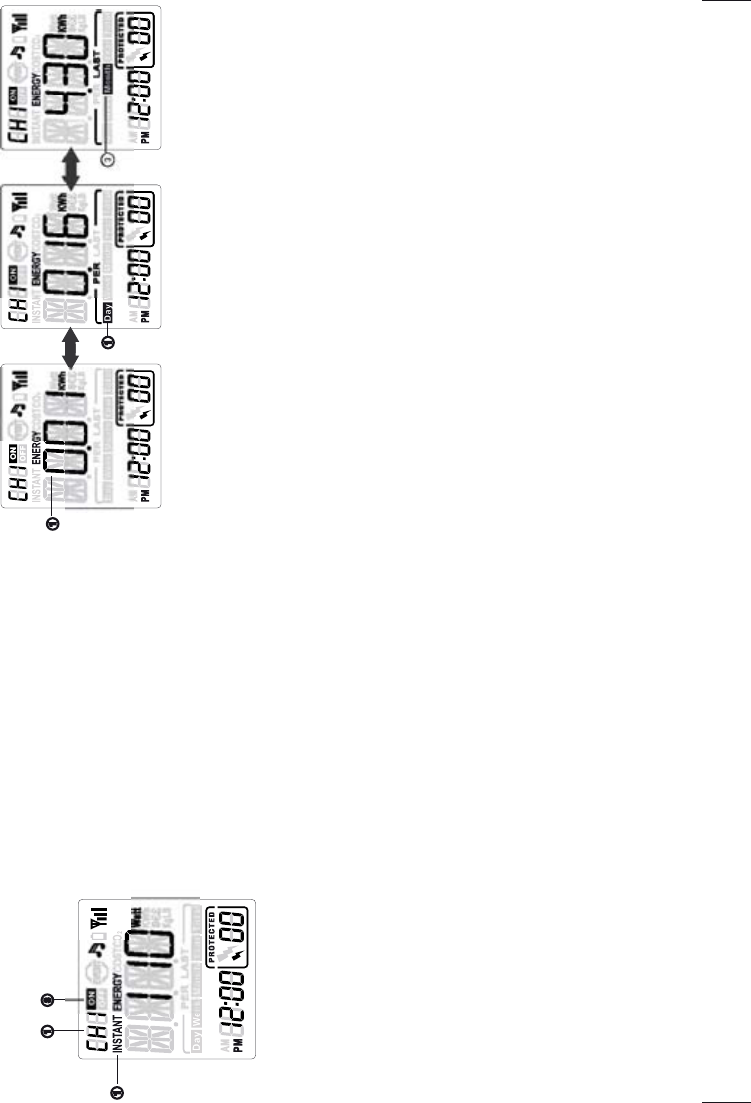
Energy Mode
1. View energy consumption in kWh for the channel
In Energy Mode, the energy monitor will first display the energy consumption in
kWh for the Channel.
2. View projected energy consumption for the channel
The energy monitor can calculate and display the projected energy consumption.
Use the right arrow key to change from energy consumption in kWh to projected
energy consumption PER DayƖPER WeekƖPER MonthƖPER Year.
3. View historic energy consumption for the channel
The energy monitor can store and display the historic energy consumption. Use
the right arrow key to change from projected energy consumption to historic
energy consumption LAST DayƖLAST WeekƖLAST MonthƖLAST YearƖTotal
(up to date).
Channel Mode (Default page)
The energy monitor will return to the default Channel Mode page when it is idle for
30 seconds.
1. Change channel in channel mode
The energy monitor can control and monitor up to 9 energy tracking surge
protectors. Each CH number represents an energy tracking surge protector.
Use the arrow key to change the channel from CH1 to CH9 to ALL channels.
2. View instant energy consumption of each channel
The energy monitor can display instant energy consumption in watt of each channel.
When CH number is changed to ALL, the energy consumption of ALL available
Channels will be displayed.
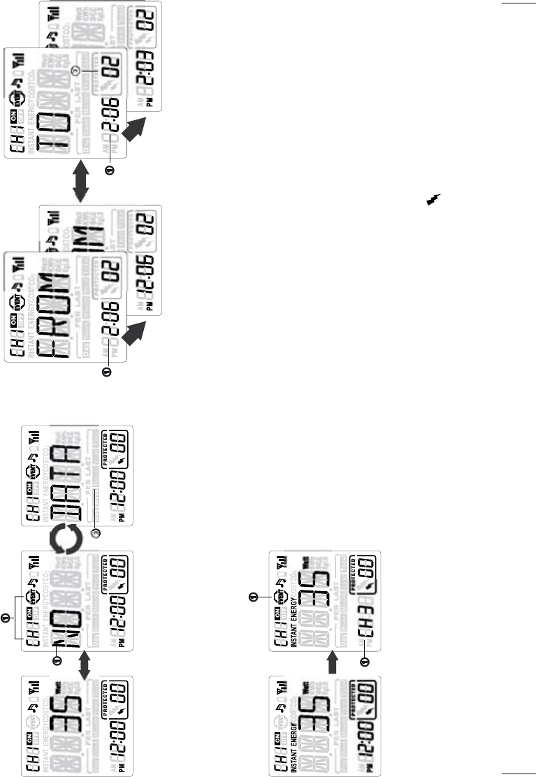
“NOT AVAL” (not available) will be displayed when the Channel does not exit.
3. Turn ON/OFF the energy saver outlets on the surge protector
The energy monitor can display the ON/OFF Status of the surge protector. Use the
ON/OFF Key on the energy monitor to turn ON and OFF the energy saver outlets of
the surge protector.
When CH number is changed to ALL, press the ON/OFF key will turn ON/OFF the
control outlets on ALL surge protectors simultaneously.
ᕡ
ᕢ
ᕣᕡ
ᕢ ᕣ
Energy
Consumption in kWh
Proj ected Energy
Consumption in kWh
Historic Energy
Consumption in kWh
GREEN POWERLINK Manual All Versions V1.0
17 GREEN POWERLINK Manual All Versions V1.
0
18
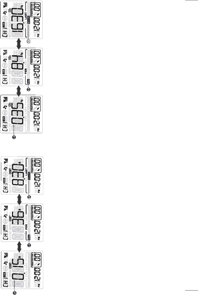
CO2 Mode
1. View carbon emission per hour for the channel
In CO2 Mode, the energy monitor will first display the carbon emission per hour
for the Channel.
2. View projected carbon emission for the channel
The energy monitor can calculate and display the projected energy cost. Use the
right arrow key to change from carbon emission per hour to projected carbon
emission PER DayƖPER WeekƖPER MonthƖPER Year.
3. View historic carbon emission for the channel
The energy monitor can store and display the historic carbon emission. Use the
right arrow key to change from projected carbon emission to historic carbon
emission LAST DayƖLAST WeekƖLAST MonthƖLAST YearƖTotal (up to date).
Event Mode
In the event of power failure or power overload happening to the energy tracking
surge protector, the energy monitor will alert with beeping and event icon on the
screen. This allows the user to be aware of the unusual power failure conditions of
home electricity.
Cost Mode
1. View energy cost per hour for the channel
In Cost Mode, the energy monitor will first display the energy cost per hour for the
Channel.
2. View projected energy cost for the channel
The energy monitor can calculate and display the projected energy cost. Use the
right arrow key to change from energy cost per hour to projected energy cost
PER DayƖPER WeekƖPER MonthƖPER Year.
3. View historic energy cost for the channel
The energy monitor can store and display the historic energy cost. Use the
right arrow key to change from projected energy cost to historic energy cost
LAST DayƖLAST WeekƖLAST MonthƖLAST YearƖTotal (up to date).
ᕡ
ᕢ ᕣ
Projected Energy Cost in $Energy Cost per hour in $ Historic Energy Cost in $
ᕡ
ᕢ ᕣ
Projected Carbon Emission in KGCarbon Emission per hour in KG Historic Carbon Emission in KG
G
REEN P
O
WERLINK M
a
n
ua
l All V
e
r
s
i
o
n
s
V1.
0
19
G
REEN P
O
WERLINK M
a
n
ua
l All V
e
r
s
i
o
n
s
V1.
0
20
View historic events for the channel
1. View what date & time the events occurred
The energy monitor can store and display historic events. In event mode, the event
icon will be flashing and first display FROM what date & time the events occurred.
2. View what date & time the events ended
The energy monitor will then display TO what date & time the events ended.
The above example shows that the event occurred from Feb 6th at 12:06PM and
ended on Feb 6th at 2:03PM.
3. View historic events for the channel in sequence
The number in lower right corner indicates how many times the events happened.
Use the arrow key to change and view events in sequence.
Surge Alert Mode
When energy tracking surge protector encounters surge events, the energy
monitor will alert with beeping and icon on the screen. This allows the user to
be aware of the unusual surge conditions of home electricity.
Instant event alert on currently browsing channel
1. When power failure / power overload happens to the currently browsing channel,
the energy monitor will alert with beeping and event icon flashing on the screen.
2. Since the remote surge protector stops working due to power failure / power
overload, NO DATA will be shown on the energy monitor.
Instant event alert insertion from other channels
1. The energy monitor will insert the event alert on the screen and alert with beeping
when event happening to other channels.
2. The event icon and CH number in lower left corner will flash to indicate what CH is
experiencing power failure / power overload conditions.
ᕡ
ᕡ
ᕢ
ᕢ
ᕣ
ᕡ
ᕢ
ᕣ
2. The icon in the lower right corner will flash and display the intensity of surge
event in minor surge (small icon) or major surge (big icon).
Note:
The instant surge alert insertion will display for short time and return to previous
display mode.
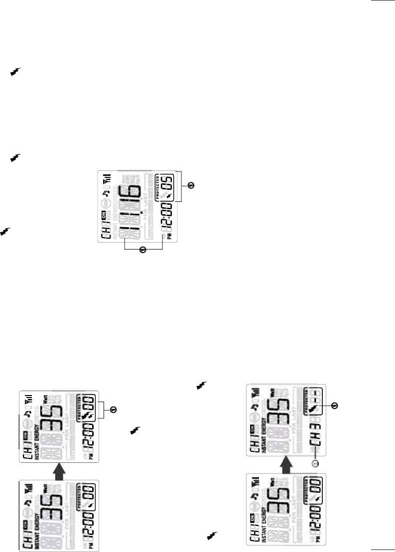
View historic surge events for the channel
1. View what date and time the surge events occurred
The energy monitor will first display what date and time the last surge event
occurred. The above example shows that the 5th surge event occurred at 12:00pm
in Nov. 16th.
2. View historic surge events for the channel in sequence
The energy monitor will store and display the surge events frequency in numbers.
Use the arrow key to change and view historic surge events in sequence.
Note:
When viewing historic surge events, the energy monitor will first display minor
surge event data. Press the mode button to go to major surge event page for detail
major surge event information.
Instant surge alert on currently browsing channel
1. When surge events happen to the currently browsing channel, the energy
monitor will alert with beeping and icon flashing on the screen. The energy
monitor will display the surge event frequency in numbers and store the surge
event data for later review.
Note:
The energy tracking surge protector can detect the intensity of the surge
events and display surge alert in minor surge (small icon) or major surge
(big icon).
Instant surge alert insertion from other channels
1. When surge event happens to other channel, the energy monitor will alert with
beeping and display what Channel is encountering surge event in lower left corner.
G
REEN P
O
WERLINK M
a
n
ua
l All V
e
r
s
i
o
n
s
V1.
0
21
G
REEN P
O
WERLINK M
a
n
ua
l All V
e
r
s
i
o
n
s
V1.
0
22
ᕡ
ᕢ
ᕡ
ᕢ
ᕡ
Advance Setup Instruction
In set-up menu, the user can perform the following setup procedures for the
energy monitor.
Press and hold the SET button for 3 seconds to access in the set-up menu. For the
first 5 advance setup options, please refer to Initial Setup Instruction in the
manual.
1. Date & Time Setup
2. Currency Setup
3. Electricity Rate Setup
4. Carbon Emission Setup
5. Audible Alarm Setup
6. Delete Event Data Setup
7. Delete Surge Event Data Setup
8. Delete History Energy Data Setup
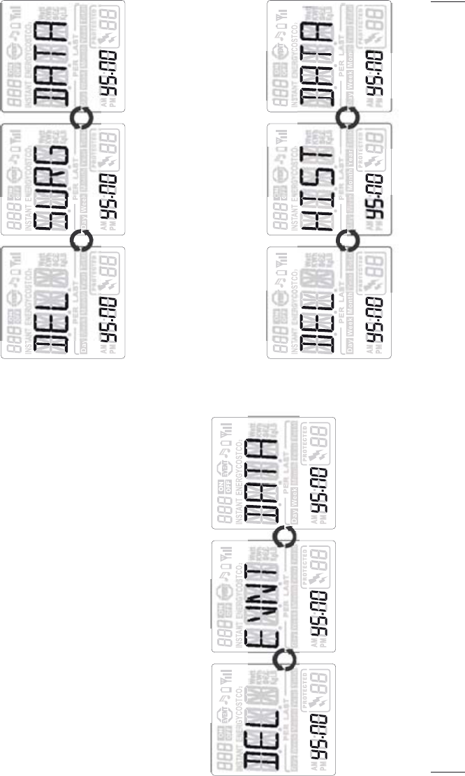
Delete Event Data Setup
1. In Delete Event Data setup page, “DELƖEVNTƖDATA” displays in looping. User
may choose to delete all the previous event data.
2. The NO option blinks first. Use the arrow key to select Yes [YS]or NO for event
data delete decision.
3. Press the SET button to proceed to Delete Surge Event Data Setup page.
Delete Surge Event Data Setup
1. In Delete Surge Event Data setup page, “DELƖSURGƖDATA” displays in
looping. User may choose to delete all the previous surge event data.
2. The NO option blinks first. Use the arrow key to select Yes [YS]or NO for surge
event data delete decision.
3. Press the SET button to proceed to Delete History Data Setup page.
Delete History Data Setup
GREEN POWERLINK Manual All Versions V1.
0
23
G
REEN POWERLINK Manual All Versions V1.
0
24

1. In Delete History Data setup page, “DELƖHISTƖDATA” displays in looping.
User may choose to delete all the previously saved KWH / COST / CO2 historic
database.
2. The NO option blinks first. Use the arrow key to select Yes [YS]or NO for
history data delete decision.
3. Press the SET button to proceed to Exit page.
Exit the Setup Page
1. In Exit page, the NO option blinks first. Use the arrow key to select Yes [YS]then
press the SET button to exit the setup menu.
2. Select NO then press SET button will allow the user to re-do setup steps.
Add Channels to the Energy Monitor by Learning
The energy monitor and the energy tracking surge protector in the kit are
pre-paired and ready to use.
You can purchase more compatible energy tracking surge protectors and expand
up to 9 CH by adding to the exiting energy monitor.
1. Hold the energy monitor close to the energy tracking surge protector.
2. In the energy monitor channel mode, use the arrow key to select which channel
you wish to add the energy tracking surge protector.
3. On the energy tracking surge protector, press and hold the LEARNING button
for 3 seconds until the green LED indicator light flashes and goes into learning
mode.
Note : you can release the button once the indicator light goes flashing
4. Within 10 seconds, press the LEARNING button on the energy monitor to add
energy tracking surge protector to the selected channel.
5. The Surge Protector will beep once to confirm that it has been successfully
added to the channel on the energy monitor.
6. Redo step 3~5 if learning is not successful.
7. Repeat step 2~5 to add more energy tracking surge protectors to different
channels on the energy monitor.
Reset the Energy Monitor to Factory Default
Please follow the instruction below to reset the energy monitor to its factory
default setting.
Note:
By performing resetting energy monitor to factory default, all saved data, setup &
channel settings will be erased.
1. Locate the reset point on top of the energy monitor.
2. Push a stylus or pen into the reset point for 5 seconds.
3. The energy monitor will be hard reset to factory default setting. Please perform
all the necessary setup and channel setting.
GREEN POWERLINK Manual All Versions V1.
0
25 GREEN POWERLINK Manual All Versions V1.
0
26
!
!
!
FEDERAL COMMUNICATIONS COMMISSION
INTERFERENCE STATEMENT
This equipment has been tested and found to comply with the limits for a Class B
digital device, pursuant to Part 15 of the FCC Rules. These limits are designed to
provide reasonable protection against harmful interference in a residential installation.
This equipment generates, uses and can radiate radio frequency energy and, if not
installed and used in accordance with the instructions, may cause harmful
interference to radio communications. However, there is no guarantee that
interference will not occur in a particular installation. If this equipment does cause
harmful interference to radio or television reception, which can be determined by
turning the equipment off and on, the user is encouraged to try to correct the
interference by one or more of the following measures:
-- Reorient or relocate the receiving antenna.
-- Increase the separation between the equipment and receiver.
-- Connect the equipment into an outlet on a circuit different from that to which the
receiver is connected.
-- Consult the dealer or an experienced radio/TV technician for help.
CAUTION:
To assure continued FCC compliance:
Any changes or modifications not expressly approved by the grantee of this device
could void the user's authority to operate the equipment.
!
!
!
This device complies with Part 15 of the FCC Rules. Operation is subject to the
following two conditions: (1) This device may not cause harmful interference, and (2)
this device must accept any interference received, including interference that may
cause undesired operation.