Powerware 9390 Ups 100160 Kva Users Manual 1604Cov
100160 kVA to the manual ed2d7d5c-1a60-4f5c-8a3a-b20788e9f1dc
2015-02-06
: Powerware Powerware-9390-Ups-100160-Kva-Users-Manual-520097 powerware-9390-ups-100160-kva-users-manual-520097 powerware pdf
Open the PDF directly: View PDF ![]() .
.
Page Count: 226 [warning: Documents this large are best viewed by clicking the View PDF Link!]

Powerware 9390 UPS
100–160 kVA
Installation and Operation Manual
®

IMPORTANT SAFETY INSTRUCTIONS
SAVE THESE INSTRUCTIONS
This manual contains important instructions that you should follow during installation and
maintenance of the UPS and batteries. Please read all instructions before operating the equipment
and save this manual for future reference.
Consignes de sécurité
CONSIGNES DE SÉCURITÉ IMPORTANTES
CONSERVER CES INSTRUCTIONS
CE MANUEL CONTIENT DES CONSIGNES DE SÉCURITÉ IMPORTANTES
ClassAEMCStatements
FCC Part 15
NOTE This equipment has been tested and found to comply with the limits for a Class A digital device,
pursuant to part 15 of the FCC Rules. These limits are designed to provide reasonable protection against
harmful interference when the equipment is operated in a commercial environment. This equipment
generates, uses, and can radiate radio frequency energy and, if not installed and used in accordance with the
instruction manual, may cause harmful interference to radio communications. Operation of this equipment
in a residential area is likely to cause harmful interference in which case the user will be required to correct
the interference at his own expense.
WARNING
This is a product for restricted sales distribution to informed partners. Installation
restrictions or additional measures may be needed to prevent disturbances.
Powerware, X-Slot, and ABM are registered trademarks and ConnectUPS is a trademark of Eaton Electrical
Inc. Modbus is a registered trademark of Modicon. IBM and AS/400 are registered trademarks of
International Business Machines Corp.
ECopyright 2004-2006 Eaton Corporation, Raleigh, NC, USA. All rights reserved. No part of this document
may be reproduced in any way without the express written approval of Eaton Corporation.

i
EATON Powerware®9390 UPS (100–160 kVA) Installation and Operation Manual S164201604 Rev B powerware.com
Table of Contents
1Introduction 1-1............................................................
1.1 Basic System Configurations 1-2.................................................
1.2 Using This Manual 1-3.........................................................
1.3 Conventions Used in This Manual 1-4............................................
1.4 Safety Warnings 1-5...........................................................
1.5 For More Information 1-6......................................................
1.6 Getting Help 1-6..............................................................
Section I – Installation
2 UPS Installation Plan and Unpacking 2-1.....................................
2.1 Creating an Installation Plan 2-1.................................................
2.2 Preparing the Site 2-1.........................................................
2.2.1 Environmental Considerations 2-2...........................................
2.2.2 Preparing for Wiring the UPS System 2-2......................................
2.3 Inspecting and Unpacking the UPS Cabinet 2-3....................................
3 Installing the UPS System 3-1................................................
3.1 Preliminary Installation Information 3-1..........................................
3.2 UPS Cabinet Installation 3-1....................................................
3.2.1 Unloading the Powerware 9390 UPS Cabinet from the Pallet 3-2..................
3.2.2 Battery Cabinet Installation 3-5..............................................
3.2.3 Integrated Distribution Cabinet Installation 3-6................................
3.2.4 Integrated Accessory Cabinet Installation 3-6..................................
3.2.5 UPS Sidecar Wiring 3-6.....................................................
3.2.6 Installing UPS External and Battery Power Wiring 3-6............................
3.2.6.1 External Wiring Installation Procedure A 3-7..............................
3.2.6.2 External Wiring Installation Procedure B 3-9...............................
3.2.6.3 Battery Wiring 3-10....................................................
3.2.7 Installing Interface Connections 3-11..........................................
3.2.7.1 TB1 and TB2 Connections 3-11...........................................
3.2.7.2 TB2 Battery Cabinet Connections 3-12....................................
3.2.7.3 X-Slot Connections 3-13................................................
3.2.8 Installing Accessories and Parallel System Control Wiring 3-14.....................
3.3 Initial Startup 3-14.............................................................
3.4 Completing the Installation Checklist 3-14.........................................
Table of Contents
ii EATON Powerware®9390 UPS (100–160 kVA) Installation and Operation Manual S164201604 Rev B powerware.com
4 Batteries 4-1...............................................................
4.1 Important Safety Instructions 4-1................................................
4.2 Installing Batteries 4-2.........................................................
4.3 Recycling the Used Battery or UPS 4-2...........................................
5 Installing a Remote Emergency Power-off Switch 5-1..........................
6 Installing Options and Accessories 6-1........................................
6.1 Installing a Powerware Hot Sync CAN Bridge Card 6-1..............................
6.2 Installing Parallel System Control Wiring 6-2......................................
6.3 Installing a Remote Monitor Panel II 6-3..........................................
6.4 Installing a Relay Interface Module II 6-4.........................................
6.5 Installing a Supervisory Contact Module II 6-6.....................................
Section II – Operation
7 Understanding UPS Operation 7-1...........................................
7.1 Looking Inside the UPS System 7-1..............................................
7.2 Single Module Reverse Transfer (RT) 7-2.........................................
7.2.1 Single Module RT Modes 7-2................................................
7.2.2 Normal Mode – RT 7-4.....................................................
7.2.3 Bypass Mode – RT 7-6......................................................
7.2.4 Battery Mode – RT 7-8.....................................................
7.3 Multiple Module Parallel System 7-9.............................................
7.3.1 Multiple Module Parallel System Modes 7-10...................................
7.3.2 Normal Mode – Parallel 7-11.................................................
7.3.3 Bypass Mode – Parallel 7-12..................................................
7.3.4 Battery Mode – Parallel 7-14.................................................
7.4 Functional Description 7-15.....................................................
7.4.1 Input Rectifier 7-15.........................................................
7.4.2 Inverter 7-15..............................................................
7.4.3 Battery Charger and Advanced Battery Management 7-15........................
7.4.4 Bypass 7-16...............................................................
7.4.5 Batteries 7-16..............................................................
Table of Contents
iii
EATON Powerware®9390 UPS (100–160 kVA) Installation and Operation Manual S164201604 Rev B powerware.com
8 Features, Options, and Accessories 8-1.......................................
8.1 UPS Standard Features 8-1.....................................................
8.1.1 Control Panel 8-1.........................................................
8.1.2 Customer Interface 8-1.....................................................
8.1.2.1 Building Alarm Monitoring 8-1..........................................
8.1.2.2 Alarm Contact 8-1....................................................
8.1.3 X-Slot Communication Bay 8-1..............................................
8.1.4 ConnectUPS-X Web/SNMP Card X-Slot Card 8-1...............................
8.1.5 Advanced Battery Management 8-2..........................................
8.1.6 LanSafe Power Management Software 8-2.....................................
8.1.7 Installation Features 8-2....................................................
8.2 Options and Accessories 8-2....................................................
8.2.1 Integrated Battery Cabinets 8-2..............................................
8.2.2 Integrated Distribution Cabinet 8-2..........................................
8.2.3 Integrated Accessory Cabinet (IAC-B, IAC-T, and IAC-D) 8-3......................
8.2.4 Powerware Hot Sync Parallel System 8-3......................................
8.2.5 Sync Control 8-3..........................................................
8.2.6 Optional X-Slot Cards 8-3...................................................
8.2.7 Mini-CSB 8-3.............................................................
8.2.8 Remote Monitor Panel II 8-4................................................
8.2.9 Relay Interface Module II 8-4................................................
8.2.10 Supervisory Contact Module II 8-4...........................................
8.3 Symbols, Controls, and Indicators 8-4............................................
9 Using the Control Panel 9-1.................................................
9.1 Using the LCD and Pushbuttons 9-2.............................................
9.2 Using the Main Menu 9-3......................................................
9.2.1 Mimic Screen 9-3.........................................................
9.2.2 Event Screens 9-4.........................................................
9.2.3 Unit Meter Screens 9-6.....................................................
9.2.4 Battery Discharge Log 9-9..................................................
9.2.5 KW Demand Log 9-11.......................................................
9.2.6 Maximum Current Log 9-19..................................................
9.2.7 System Meters Screens 9-28.................................................
9.2.8 System Setup Level 0 Screens 9-33............................................
9.2.9 System Setup Level 1 Screens 9-36............................................
Table of Contents
iv EATON Powerware®9390 UPS (100–160 kVA) Installation and Operation Manual S164201604 Rev B powerware.com
9.3 System Controls Screen 9-45....................................................
9.4 Load Off Screen 9-47...........................................................
9.5 Reading the Status Indicators 9-48................................................
10 UPS Operating Instructions 10-1..............................................
10.1 Single Module Operation 10-1...................................................
10.1.1 Starting the UPS in Normal Mode 10-1........................................
10.1.2 Starting the UPS in Bypass Mode 10-2.........................................
10.1.3 Starting the Power Module 10-3..............................................
10.1.4 Transfer from Normal to Bypass Mode 10-3....................................
10.1.5 Transfer from Bypass to Normal Mode 10-4....................................
10.1.6 Transfer from Normal to Bypass Mode and Shut Down UPS 10-4..................
10.1.7 UPS and Critical Load Shutdown 10-5.........................................
10.1.8 Charger Control 10-5.......................................................
10.1.9 Using the UPS LOAD OFF Pushbutton 10-6.....................................
10.1.10 Using the Remote Emergency Power-off Switch 10-7.............................
10.2 Multiple Module Parallel Operation 10-8..........................................
10.2.1 Starting the Parallel System in Normal Mode 10-8...............................
10.2.2 Starting the Parallel System in Bypass Mode 10-9................................
10.2.3 Transfer Parallel System from Normal to Bypass Mode 10-10.......................
10.2.4 Transfer Parallel System from Bypass to Normal Mode 10-10.......................
10.2.5 Single UPM Shutdown 10-11..................................................
10.2.6 Restarting a Single UPM 10-11.................................................
10.2.7 Parallel System and Critical Load Shutdown 10-12................................
10.2.8 Using the UPS LOAD OFF Pushbutton 10-13.....................................
10.2.9 Using the Parallel System Remote Emergency Power-off Switch 10-14...............
11 Using Features and Options 11-1..............................................
11.1 Building Alarm Monitoring 11-1..................................................
11.2 General Purpose Relay Contact 11-1..............................................
11.3 Optional Remote Monitor Panel II 11-2...........................................
11.4 Relay Interface Module II 11-4...................................................
11.5 Supervisory Contact Module II 11-5...............................................
12 Responding to System Events 12-1............................................
12.1 General 12-1..................................................................
12.2 System Event Horns 12-1........................................................
12.3 System Event Indicators 12-1....................................................
12.4 System Event Messages 12-1.....................................................
Table of Contents
v
EATON Powerware®9390 UPS (100–160 kVA) Installation and Operation Manual S164201604 Rev B powerware.com
13 Communication 13-1.........................................................
13.1 X-Slot Cards 13-1..............................................................
13.2 LanSafe Power Management Software 13-2........................................
13.3 Remote Notification 13-2.......................................................
13.4 Terminal Mode 13-3...........................................................
13.4.1 Display UPS Control Panel 13-3...............................................
13.4.2 Event History Log 13-4......................................................
14 Maintaining the UPS System 14-1.............................................
14.1 Important Safety Instructions 14-1................................................
14.2 Performing Preventive Maintenance 14-2..........................................
14.2.1 DAILY Maintenance 14-2....................................................
14.2.2 MONTHLY Maintenance 14-3.................................................
14.2.3 ANNUAL Maintenance 14-3..................................................
14.2.4 BATTERY Maintenance 14-3..................................................
14.3 Maintenance Training 14-3......................................................
15 Product Specifications 15-1...................................................
15.1 Model Numbers 15-1...........................................................
15.2 SingleModuleSpecifications 15-1................................................
15.2.1 UPS System Input 15-1......................................................
15.2.2 UPS System Output 15-2....................................................
15.2.3 Environmental 15-2.........................................................
15.3 Multiple Module Parallel Specifications 15-3.......................................
15.3.1 UPM Input 15-3............................................................
15.3.2 UPM Output 15-3..........................................................
15.3.3 Environmental 15-3.........................................................
15.3.4 Battery 15-3...............................................................
15.3.5 Module Tie Cabinet Input 15-3...............................................
15.3.6 Module Tie Cabinet Output 15-3.............................................
Appendix A – Installation Information A-1.........................................
Warranty W-1...................................................................
Table of Contents
vi EATON Powerware®9390 UPS (100–160 kVA) Installation and Operation Manual S164201604 Rev B powerware.com
This page intentionally left blank.

vii
EATON Powerware®9390 UPS (100–160 kVA) Installation and Operation Manual S164201604 Rev B powerware.com
Table of Contents
Figure 1-1. Powerware 9390 UPS (100–160 kVA) Cabinet 1-1...................................
Figure 2-1. Powerware 9390 UPS (100–160 kVA) Cabinet as Shipped on Pallet 2-3.................
Figure 3-1. Removing Front Shipping Bracket on the Powerware 9390 UPS 3-3....................
Figure 3-2. Removing Rear Shipping Bracket on the Powerware 9390 UPS 3-4....................
Figure 5-1. REPO Switch 5-1...............................................................
Figure 6-1. Powerware Hot Sync CAN Bridge Card 6-1........................................
Figure 6-2. Supervisory Contact Module II TB2 6-7...........................................
Figure 7-1. Main Elements of the UPS System 7-1............................................
Figure 7-2. Path of Current Through the UPS in Normal Mode – RT 7-4..........................
Figure 7-3. Path of Current Through the UPS in Bypass Mode – RT 7-6..........................
Figure 7-4. Path of Current Through the UPS in Battery Mode – RT 7-8..........................
Figure 7-5. Path of Current through the UPMs in Normal Mode – Parallel 7-11.....................
Figure 7-6. Path of Current through the UPMs in Bypass Mode – Parallel 7-12.....................
Figure 7-7. Path of Current through the UPMs in Battery Mode – Parallel 7-14.....................
Figure 9-1. UPS Control Panel 9-1..........................................................
Figure 9-2. Parts of the LCD 9-2...........................................................
Figure 9-3. Main Menu and Mimic Screen (Normal Mode) 9-3..................................
Figure 9-4. Active Events Screen 9-4........................................................
Figure 9-5. History Screen 9-5.............................................................
Figure 9-6. Unit Output Meter Screen 9-6...................................................
Figure 9-7. Unit Input Meter Screen 9-7....................................................
Figure 9-8. Unit Bypass Meter Screen 9-7...................................................
Figure 9-9. Unit Battery Meter Screen 9-8...................................................
Figure 9-10. Unit Output Current (Load) Meter Screen 9-8....................................
Figure 9-11. Battery Discharge Log Summary Screen 9-9.......................................
Figure 9-12. Battery Discharge Log Screen 9-10...............................................
Figure 9-13. KW Demand Log Summary Screen 9-11...........................................
Figure 9-14. KW Demand Log Screen 9-12...................................................
Figure 9-15. Current KW Demand Log Setup Screen 1 9-13.....................................
Figure 9-16. Current KW Demand Log Setup Screen 2 9-14.....................................
Figure 9-17. Time Interval Monitored Setup Screen 9-15.......................................
Figure 9-18. Time Interval Monitored Setup Save Screen 9-16...................................
Figure 9-19. Maximum Level (KW) Setup Screen 9-17..........................................
Figure 9-20. Maximum Level (KW) Setup Save Screen 9-18......................................
Figure 9-21. Maximum Current Log Summary Screen 9-19......................................
Figure 9-22. Maximum Current Log Screen (Three-Phase Measurement) 9-20......................
Figure 9-23. Maximum Current Log Screen (Individual Phase Measurement) 9-21..................
Table of Contents
viii EATON Powerware®9390 UPS (100–160 kVA) Installation and Operation Manual S164201604 Rev B powerware.com
Figure 9-24. Maximum Current Log Setup Screen 1 9-21.......................................
Figure 9-25. Maximum Current Log Setup Screen 2 9-22.......................................
Figure 9-26. Time Interval Monitored Setup Screen 9-23.......................................
Figure 9-27. Time Interval Monitored Setup Save Screen 9-24...................................
Figure 9-28. Maximum % of Full Load Setup Screen 9-25.......................................
Figure 9-29. Maximum % of Full Load Setup Save Screen 9-26...................................
Figure 9-30. Calculation Method Setup Screen 9-27...........................................
Figure 9-31. System Meters Screen 9-28.....................................................
Figure 9-32. Total System Output Meter Screen 9-29..........................................
Figure 9-33. Output Unit X Meter Screen 9-30................................................
Figure 9-34. Input Unit X Meter Screen 9-31..................................................
Figure 9-35. Bypass Unit X Meter Screen 9-31................................................
Figure 9-36. Battery Unit X Meter Screen 9-32................................................
Figure 9-37. Output Current (Load) Unit X Meter Screen 9-32...................................
Figure 9-38. System Setup Level 0 Screen 9-33................................................
Figure 9-39. Contrast Adjust Screen 9-34.....................................................
Figure 9-40. Versions Screen 9-35...........................................................
Figure 9-41. Unit Type Screen 9-35..........................................................
Figure 9-42. Enter Password Screen 9-36.....................................................
Figure 9-43. System Setup Level 1 Screen 9-37................................................
Figure 9-44. Change Password Screen 9-38...................................................
Figure 9-45. Change Password Save Screen 9-39...............................................
Figure 9-46. Time Format Screen 9-40.......................................................
Figure 9-47. Set Date and Time MM/DD/YYYY Screen 9-41......................................
Figure 9-48. Set Date and Time DD/MM/YYYY Screen 9-42......................................
Figure 9-49. COM Port Setup Screen 9-43....................................................
Figure 9-50. COM Setup Screen 9-44........................................................
Figure 9-51. System Controls Screen 1 9-45..................................................
Figure 9-52. System Controls Screen 2 9-46..................................................
Figure 9-53. Load Off Screen 9-47..........................................................
Figure 11-1. Remote Monitor Panel II 11-2...................................................
Figure 11-2. Relay Interface Module II 11-4...................................................
Figure 11-3. Supervisory Contact Module II 11-5..............................................
Figure 13-1. Optional X-Slot Cards 13-2......................................................
Figure 13-2. Sample Event History Log 13-5..................................................
1-1
EATON Powerware®9390 UPS (100–160 kVA) Installation and Operation Manual S164201604 Rev B powerware.com
Chapter 1 Introduction
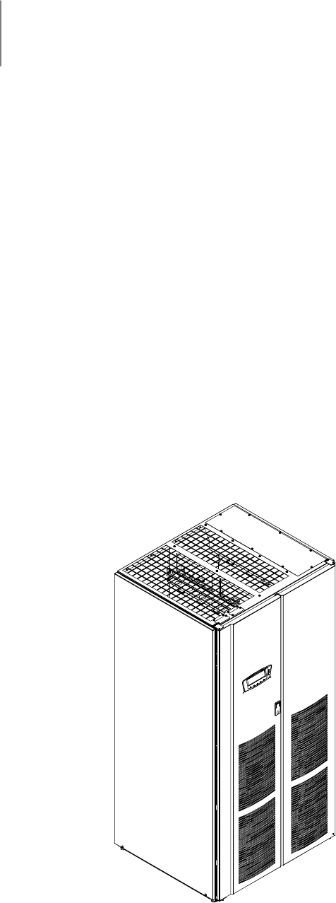
The Powerware®9390 uninterruptible power supply (UPS) is a true online, continuous-duty,
transformerless, double-conversion, solid-state, three-phase system, providing conditioned
and uninterruptible AC power to protect the customer’s load from all nine power failures.
The Powerware 9390 UPS is available as a single module or a multiple module parallel
system (see paragraph 1.1).
The Powerware online power protection system is used to prevent loss of valuable
electronic information, minimize equipment downtime, and minimize the adverse effect on
production equipment due to unexpected power problems.
The Powerware 9390 UPS continually monitors incoming electrical power and removes the
surges, spikes, sags, and other irregularities that are inherent in commercial utility power.
Working with a building’s electrical system, the UPS system supplies clean, consistent
power that sensitive electronic equipment requires for reliable operation. During
brownouts, blackouts, and other power interruptions, batteries provide emergency power
to safeguard operation.
The UPS system is housed in a single, free-standing cabinet with safety shields behind the
door for hazardous voltage protection. The cabinet es the battery and distribution cabinets
in style and color and can be installed in line-up-and-match or standalone configurations.
Figure 1-1 shows the Powerware 9390 UPS (100–160 kVA).
Figure 1-1. Powerware 9390 UPS (100–160 kVA) Cabinet
Introduction
1-2 EATON Powerware®9390 UPS (100–160 kVA) Installation and Operation Manual S164201604 Rev B powerware.com
1.1 Basic System Configurations
The following basic UPS system configurations are possible:
쑺Single module UPS and one to four battery cabinets
쑺Single module UPS with UPS Sidecar (maintenance bypass or 1+1 tie configuration) and
one to four battery cabinets
쑺Single module UPS, one to four battery cabinets, and an optional Integrated Distribution
Cabinet (IDC)
쑺Single module UPS, one to four battery cabinets, and an optional Integrated Accessory
Cabinet (IAC) (maintenance bypass, 1+1 tie, or 1+1 tie with maintenance bypass
configuration)
쑺Single module UPS, one to four battery cabinets, and an optional Integrated Accessory
Cabinet (IAC) (distribution configuration)
쑺Powerware Hot Sync parallel system with two UPS modules, one to four battery cabinets
for each UPS, and an optional module tie cabinet
- One capacity/one redundant (1+1)
- Two capacity (2+0)
쑺Powerware Hot Sync parallel system with three UPS modules, one to four battery
cabinets for each UPS, and an optional module tie cabinet
- Two capacity/one redundant (2+1)
- Three capacity (3+0)
쑺Powerware Hot Sync parallel system with four UPS modules, one to four battery cabinets
for each UPS, and an optional module tie cabinet
- Three capacity/one redundant (3+1)
- Four capacity (4+0)
쑺Powerware Hot Sync parallel system with two UPS modules, one to four battery cabinets
for each UPS, an optional module tie cabinet, and an optional IDC
- One capacity/one redundant (1+1)
- Two capacity (2+0)
쑺Powerware Hot Sync parallel system with three UPS modules, one to four battery
cabinets for each UPS, an optional module tie cabinet, and an optional IDC
- Two capacity/one redundant (2+1)
- Three capacity (3+0)
쑺Powerware Hot Sync parallel system with four UPS modules, one to four battery cabinets
for each UPS, an optional module tie cabinet, and an optional IDC
- Three capacity/one redundant (3+1)
- Four capacity (4+0)
The UPS system configuration can be enhanced by adding optional accessories such as a
Remote Emergency Power-off (REPO) control, Remote Monitor Panel II (RMP II), or X-Slot®
communication cards.
Introduction
1-3
EATON Powerware®9390 UPS (100–160 kVA) Installation and Operation Manual S164201604 Rev B powerware.com
1.2 Using This Manual
This manual describes how to install and operate the Powerware 9390 UPS (100–160 kVA)
cabinet. Read and understand the procedures described in this manual to ensure
trouble-free installation and operation. In particular, be thoroughly familiar with the REPO
procedure (see page 10-7).
The information in this manual is divided into the sections and chapters listed. The system,
options, and accessories being installed dictate which parts of this manual should be read.
At a minimum, Chapters 1 through 3 and 8 through 10 should be examined.
쑺Chapter 1, “Introduction” – provides a brief description of the UPS system, a
description of the content of each chapter, text conventions used in the manual, safety
warnings, and reference information.
Section I, Installation
쑺Chapter 2, “UPS Installation Plan and Unpacking” – explains how to prepare the site
for the installation of the UPS system. It discusses equipment environmental
requirements, inspecting, and unpacking cabinets.
쑺Chapter 3, “Installing the UPS System” – describes how to install and wire the UPS
cabinet and optional equipment.
쑺Chapter 4, “Batteries” – provides battery safety and installation information.
쑺Chapter 5, “Installing a Remote Emergency Power-off Control” – contains information
for installing the optional REPO control.
쑺Chapter 6, “Installing Options and Accessories” – contains information for installing an
X-Slot Powerware Hot Sync CAN Bridge Card, parallel control wiring, an RMP II, a Relay
Interface Module II (RIM II), or a Supervisory Contact Module II (SCM II).
Section II, Operation
쑺Chapter 7, “Understanding UPS Operation” – provides information on why and how a
UPS works.
쑺Chapter8,“Features,Options,andAccessories”–describes the standard and optional
UPS features and available accessories.
쑺Chapter 9, “Using the Control Panel” – describes the controls and indicators found on
the control panel and shows the various information screens displayed on the LCD.
쑺Chapter 10, “UPS Operating Instructions” – contains startup and shutdown procedures
for the UPS system.
쑺Chapter 11, “Using Features and Options” – contains descriptions and instructions for
the UPS system features and options.
쑺Chapter 12, “Responding to System Events” – listsallthealarmsandnoticesthatoccur
during operation of the UPS system.
쑺Chapter 13, “Communication” – describes the communication features of the UPS
system.

Introduction
1-4 EATON Powerware®9390 UPS (100–160 kVA) Installation and Operation Manual S164201604 Rev B powerware.com
쑺Chapter 14, “Maintaining the UPS System” – contains maintenance instructions for the
UPS system.
쑺Chapter 15, “Product Specifications” – provides detailed specifications for the UPS
system.
쑺Appendix A, “Installation Information” – contains important information on wiring
requirements and recommendations, and important diagrams of the cabinets’
mechanical details and electrical access.
쑺Warranty – provides the Powerware warranty for this product.
Read through each procedure before beginning the procedure. Perform only those
procedures that apply to the UPS system being installed or operated.
1.3 Conventions Used in This Manual
This manual uses these type conventions:
쑺Bold type highlights important concepts in discussions, key terms in procedures, and
menu options, or represents a command or option that you type or enter at a prompt.
쑺Italic type highlights notes and new terms where they are defined.
쑺Screen type represents information that appears on the screen or LCD.
Icon Description
Information notes call attention to important features or instructions.
[Keys] Brackets are used when referring to a specific key, such as [Enter] or [Ctrl].
In this manual, the term UPS refers only to the UPS cabinet and its internal elements. The
term UPS system refers to the entire power protection system – the UPS cabinet, the
battery cabinet, and options or accessories installed.

Introduction
1-5
EATON Powerware®9390 UPS (100–160 kVA) Installation and Operation Manual S164201604 Rev B powerware.com
1.4 Safety Warnings
IMPORTANT SAFETY INSTRUCTIONS
SAVE THESE INSTRUCTIONS
This manual contains important instructions that should be followed during installation and
maintenance of the UPS and batteries. Please read all instructions before operating the
equipment and save this manual for future reference.
The UPS cabinet is designed for industrial or computer room applications, and contains safety
shields behind the doors. However, the UPS system is a sophisticated power system and
should be handled with appropriate care.
DANGER
This UPS contains LETHAL VOLTAGES. All repairs and service should be performed by
AUTHORIZED SERVICE PERSONNEL ONLY.ThereareNO USER SERVICEABLE PARTS inside
the UPS.
WARNING
쑺The UPS system contains its own energy source (batteries). The output terminals may carry
live voltage even when the UPS is disconnected from an AC source.
쑺To reduce the risk of fire or electric shock, install this UPS in a temperature and humidity
controlled, indoor environment, free of conductive contaminants. Ambient temperature
must not exceed 40°C (104°F). Do not operate near water or excessive humidity
(95% maximum). The system is not intended for outdoor use.
쑺Ensure all power is disconnected before performing installation or service.
CAUTION
쑺Batteries can present a risk of electrical shock or burn from high short-circuit current.
Observe proper precautions. Servicing should be performed by qualified service personnel
knowledgeable of batteries and required precautions. Keep unauthorized personnel away
from batteries.
쑺Proper disposal of batteries is required. Refer to local codes for disposal requirements.
쑺Never dispose of batteries in a fire. Batteries may explode when exposed to flame.
쑺Keep the UPS doors closed to ensure proper cooling airflow and to protect personnel from
dangerous voltages inside the unit.
쑺Do not operate the UPS system close to gas or electric heat sources.
쑺The operating environment should be maintained within the parameters stated in this
manual.
쑺Keep surroundings uncluttered, clean, and free from excess moisture.
쑺Observe all DANGER, CAUTION, and WARNING notices affixed to the inside and outside of
the equipment.
Introduction
1-6 EATON Powerware®9390 UPS (100–160 kVA) Installation and Operation Manual S164201604 Rev B powerware.com
1.5 For More Information
Refer to the Powerware 9390 Integrated Battery Cabinet (Models IBC-S and IBC-L)
Installation Manual (164201536) for the following additional information:
쑺Integrated Battery Cabinet (IBC) installation instructions, including site preparation,
planning for installation, wiring, and safety information.
쑺Detailed illustrations of the cabinet, including dimension and connection point drawings.
Refer to the Powerware 9390 Integrated Distribution Cabinet (160 kVA) Installation and
Operation Manual, (164201560), the Powerware 9390 Integrated Accessory Cabinet (IAC-B
and IAC-T Configurations) Installation and Operation Manual (164201590), the Powerware
9390 Integrated Accessory Cabinet (IAC-D Configuration) Installation and Operation Manual
(164201591), the Powerware 9390 UPS Sidecar Installation and Operation Manual
(164201586), or the Powerware 9390 Sync Control Installation and Operation Manual
(164201571), as applicable, for the following additional information:
쑺Installation instructions, including site preparation, planning for installation, and wiring
and safety information. Detailed illustrations of the cabinet with dimensional and
connection point drawings are provided.
쑺Operation, including controls, functions of the standard and optional features,
procedures for using with the UPS, and information about maintenance.
Visit www.powerware.com or contact your Eaton service representative for information on
how to obtain copies of these manuals
1.6 Getting Help
If help is needed with any of the following:
쑺Scheduling initial startup
쑺Regional locations and telephone numbers
쑺A question about any of the information in this manual
쑺A question this manual does not answer
Please call the Eaton Help Desk for Powerware products at:
In the United States 1-800-843-9433 or 1-919-870-3028
In Canada 1-800-461-9166
All other countries Call your service representative

1-1
EATON Powerware®9390 UPS (100–160 kVA) Installation and Operation Manual S164201604 Rev B powerware.com
Section I Installation

1-2 EATON Powerware®9390 UPS (100–160 kVA) Installation and Operation Manual S164201604 Rev B powerware.com
This page intentionally left blank.

2-1
EATON Powerware®9390 UPS (100–160 kVA) Installation and Operation Manual S164201604 Rev B powerware.com
Chapter 2 UPS Installation Plan and Unpacking
Use the following basic sequence of steps to install the UPS:
1. Create an installation plan for the UPS system (Chapter 2).
2. Prepare your site for the UPS system (Chapter 2).
3. Inspect and unpack the UPS cabinet (Chapter 2).
4. Unload and install the UPS cabinet, and wire the system (Chapter 3).
5. Install features, accessories, or options, as applicable (Chapters 5 and 6).
6. Complete the Installation Checklist (Chapter 3).
7. Have authorized service personnel perform preliminary operational checks and
startup.
NOTE Startup and operational checks must be performed by an authorized Eaton
Customer Service Engineer, or the warranty terms specified on page W-1 become void.
This service is offered as part of the sales contract for the UPS. Contact service in
advance (usually a two-week notice is required) to reserve a preferred startup date.
2.1 Creating an Installation Plan
Before installing the UPS system, read and understand how this manual applies to the
system being installed. Use the procedures and illustrations in the following chapters to
create a logical plan for installing the system.
2.2 Preparing the Site
For the UPS system to operate at peak efficiency, the installation site should meet the
environmental parameters outlined in this manual. If the UPS is to be operated at an
altitude higher than 1500m (5000 ft), contact your Eaton service representative for
important information about high altitude operation. The operating environment must
meet the weight, clearance, and environmental requirements specified in Drawing
164201604-2 on page A-3 and size requirements specified on Drawing 164201604-9
starting on page A-46.
The UPS cabinets use forced air cooling to regulate internal component temperature. Air
inlets are in the front of the cabinet and outlets are in the top. You must allow clearance in
front of and above each cabinet for proper air circulation.

UPS Installation Plan and Unpacking
2-2 EATON Powerware®9390 UPS (100–160 kVA) Installation and Operation Manual S164201604 Rev B powerware.com
2.2.1 Environmental Considerations
The life of the UPS system is adversely affected if the installation does not meet the
following guidelines:
쑺The system must be installed on a level floorsuitableforcomputerorelectronic
equipment.
쑺The system must be installed in a temperature and humidity controlled indoor area free
of conductive contaminants.
Failure to follow guidelines may void your warranty.
2.2.2 Preparing for Wiring the UPS System
NOTE If installing, as part of the UPS system, a maintenance bypass without a rectifier
input breaker, a minimum of two separate feeds with upstream feeder breakers, or one
feed with two upstream feeder breakers, must be provided: one for the UPS and one for
the maintenance bypass input. DO NOT use one feed or a single feeder breaker to
supply both the UPS and the maintenance bypass.
For external wiring requirements, including the minimum AWG size of external wiring, see
Table E through Table G starting on page A-12. The power wiring connections for this
equipment are rated at 90°C. If wire is run in an ambient temperature greater than 30°C,
higher temperature wire and/or larger size wire may be necessary
Control wiring for Emergency Power-off (EPO) and optional accessories (such as building
alarms and monitoring interface) should be connected at the customer interface terminal
blocks located inside the UPS.
LAN and telephone drops, for use with X-Slot connectivity cards, must be supplied by
facility planners or the customer.
UPS Installation Plan and Unpacking
2-3
EATON Powerware®9390 UPS (100–160 kVA) Installation and Operation Manual S164201604 Rev B powerware.com
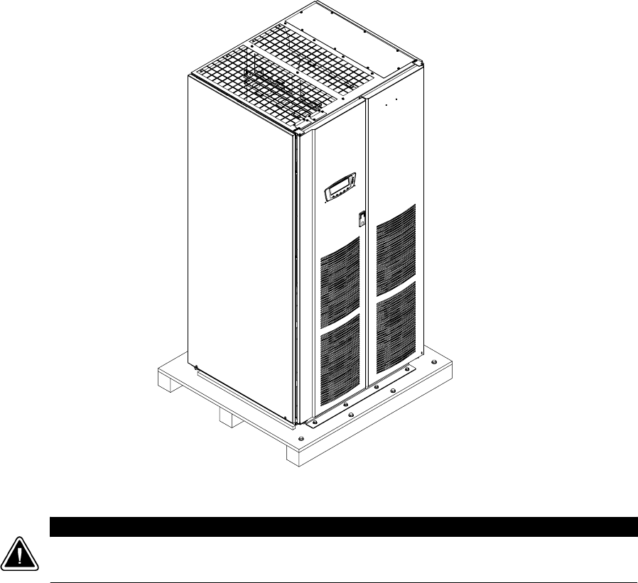
2.3 Inspecting and Unpacking the UPS Cabinet
The cabinet is shipped bolted to a wooden pallet and protected with outer protective
packaging material (see Figure 2-1).
Figure 2-1. Powerware 9390 UPS (100–160 kVA) Cabinet as Shipped on Pallet
CAUTION
The UPS cabinet is heavy (see Table A on page A-3). If unpacking instructions are not closely
followed, the cabinet may tip and cause serious injury.

UPS Installation Plan and Unpacking
2-4 EATON Powerware®9390 UPS (100–160 kVA) Installation and Operation Manual S164201604 Rev B powerware.com
1. Carefully inspect the outer packaging for evidence of damage during transit.
CAUTION
Do not install a damaged cabinet. Report any damage to the carrier and contact your Eaton
service representative immediately.
2. Use a forklift or pallet jack to move the packaged cabinet to the installation site,
or as close as possible, before unpacking. Insert the forklift or pallet jack forks
between the pallet supports on the bottom of the unit.
NOTE Verify that the forklift or pallet jack is rated to handle the weight of the cabinet
(see Table A on page A-3 for cabinet weight).
CAUTION
Do not tilt the UPS cabinet more than 10° from vertical or the cabinet may tip over.
3. Set the pallet on a firm, level surface, allowing a minimum clearance of 3m (10 ft)
on each side for removing the cabinet from the pallet.
NOTE The UPS cabinet is shipped with a debris shield covering the ventilation grill on
top of the unit. Do not remove the debris shield until installation is complete.
4. Remove the protective covering from the cabinet.
5. Remove the packing material, and discard or recycle in a responsible manner.
6. After removing the protective covering, inspect the contents for any evidence of
physical damage, and compare each item with the Bill of Lading. If damage has
occurred or shortages are evident, contact your Eaton service representative
immediately to determine the extent of the damage and its impact upon further
installation.
NOTE While waiting for installation, protect the unpacked cabinet from moisture, dust,
and other harmful contaminants. Failure to store and protect the UPS properly may
void your warranty.

3-1
EATON Powerware®9390 UPS (100–160 kVA) Installation and Operation Manual S164201604 Rev B powerware.com
Chapter 3 Installing the UPS System
3.1 Preliminary Installation Information
WARNING
Installation should be performed only by qualified personnel.
Refer to the following while installing the UPS system:
쑺Appendix A contains installation drawings and additional installation notes.
쑺Dimensions are in millimeters and inches.
쑺Do not tilt the cabinets more than 10° during installation.
쑺The conduit landing plates are to be removed to add conduit landing holes as required.
Plate material is 16 gauge steel (1.5 mm/0.06″thick).
쑺Thecabinetsmustbeinstalledonalevelfloorsuitableforcomputerorelectronic
equipment.
쑺If perforated floor tiles are required for ventilation, place them in front of the UPS. See
Table A on page A-3 for equipment weight and point loading.
쑺Details about control wiring are provided in each procedure for connecting options and
features. Drawing 164201604-8 and Table R through Table X starting on page A-33
identify the control wiring terminations.
3.2 UPS Cabinet Installation
To install a UPS cabinet, perform the procedures in the following paragraphs.
NOTE When a line-up-and-match UPS system is ordered together with battery cabinets,
the first battery cabinet is supplied with two cosmetic covers. The UPS cabinet,
additional battery cabinets, and other ancillary cabinets are supplied without cosmetic
covers.
NOTE When a UPS system is ordered together with battery cabinets for standalone
installation, the first battery cabinet is supplied with two cosmetic covers. Additional
battery cabinets are supplied without cosmetic covers. Cosmetic covers must be ordered
for the UPS cabinet and/or other ancillary cabinets.

Installing the UPS System
3-2 EATON Powerware®9390 UPS (100–160 kVA) Installation and Operation Manual S164201604 Rev B powerware.com
3.2.1 Unloading the Powerware 9390 UPS Cabinet from the Pallet
The UPS cabinet is bolted to a wooden pallet supported by wood skids. To remove the
pallet, perform the following procedure:
WARNING
The UPS cabinet is heavy. See Table A on page A-3 for weight of cabinets. If unloading
instructions are not closely followed, the cabinet may cause serious injury.
CAUTION
Donottiltcabinetsmorethan10°fromvertical.
1. If not already accomplished, use a forklift or pallet jack to move the cabinet to the
installation area, or as close as possible, before unloading from the pallet. Insert
theforkliftorpalletjackforksbetween the skids on the bottom of the unit.
NOTE Verify that the forklift or pallet jack is rated to handle the weight of the cabinet
(see Table A on page A-3 for cabinet weight).
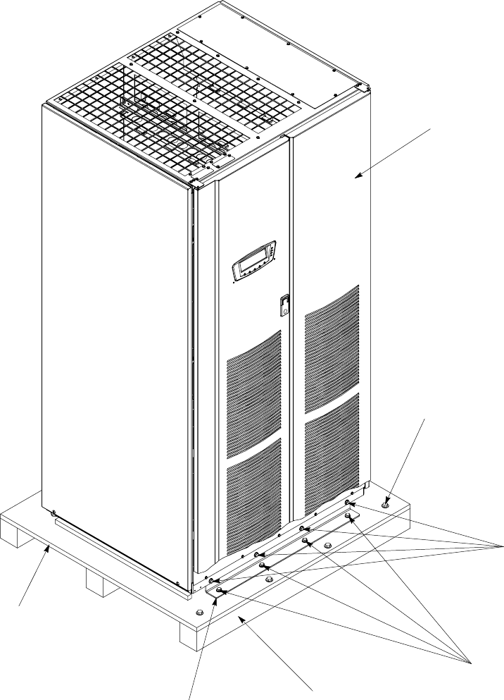
2. Unfasten the front door latch and swing the door open (see Figure 3-1).
3. Remove the doors. Remove the retaining screws located inside each door at the
top and bottom hinge pivot points, then lift the door off. Retain the hardware for
later use.
4. If the leveling feet are not fully retracted, turn the leveling feet until they are
retracted.
5. Remove the four bolts securing the front shipping bracket to the cabinet and four
bolts securing the bracket to the pallet (see Figure 3-1). Remove the front shipping
bracket. If installing the cabinet permanently, retain the shipping bracket and
securing hardware for later use.
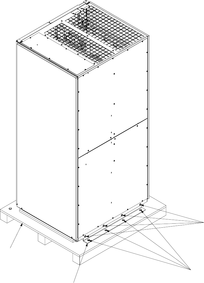
6. Remove the four bolts securing the rear shipping bracket to the pallet. Do NOT
remove the four bolts securing the bracket to the cabinet (see Figure 3-2 on
page 3-4).
7. Remove the four bolts securing the removable skid and remove the skid (see
Figure 3-1).
Installing the UPS System
3-3
EATON Powerware®9390 UPS (100–160 kVA) Installation and Operation Manual S164201604 Rev B powerware.com
Shipping
Bracket Bolts
Front View
Pallet
Vented Front Doors
Front Shipping Bracket
Shipping
Bracket Bolts
Removable Skid
Skid Bolts
Figure 3-1. Removing Front Shipping Bracket on the Powerware 9390 UPS
Installing the UPS System
3-4 EATON Powerware®9390 UPS (100–160 kVA) Installation and Operation Manual S164201604 Rev B powerware.com
Rear Shipping Bracket
Pallet
Rear View
Shipping
Bracket Bolts
Shipping
Bracket Bolts
Figure 3-2. Removing Rear Shipping Bracket on the Powerware 9390 UPS

Installing the UPS System
3-5
EATON Powerware®9390 UPS (100–160 kVA) Installation and Operation Manual S164201604 Rev B powerware.com
NOTE In the following step the pallet tilts and acts as a ramp once the cabinet is rolled
beyond the the center of the pallet. Be sure to restrain the cabinet as it continues to roll
down the pallet/ramp. The rear shipping bracket will act as a brake to assist
restraining the cabinet.
WARNING
Do not stand directly in front of the pallet while unloading the cabinet. If unloading
instructions are not closely followed, the cabinet may cause serious injury.
8. Slowly roll the cabinet toward the front of the pallet. Once the pallet tilts,
continue rolling the cabinet down the pallet until the cabinet is clear of the pallet.
9. Remove the four bolts securing the rear shipping bracket to the cabinet (see
Figure 3-2). If installing the cabinet permanently, retain the shipping bracket and
securing hardware for later use.
10. Roll the cabinet to the final installation location.
11. If installing the cabinet permanently, retain the shipping brackets and hardware;
otherwise, discard or recycle the pallet and shipping brackets in a responsible
manner.
12. If permanently mounting the system, proceed to Step 15; otherwise, continue to
Step 13.
13. Secure the UPS cabinet in position by lowering the leveling feet until the cabinet is
not resting on the casters and the cabinet is level.
14. If installing battery and distribution cabinets, proceed to paragraphs 3.2.2 and
3.2.3; otherwise, proceed to paragraph 3.2.6.
15. Using the retained hardware, reinstall the shipping brackets removed in Step 6 to
the front and rear of the UPS cabinet with the angle facing outward (see
Figure 3-1 and Figure 3-2).
16. Secure the cabinet to the floor with contractor-supplied hardware.
17. If installing battery and distribution cabinets, proceed to paragraphs 3.2.2 and
3.2.3; otherwise, proceed to paragraph 3.2.6.
3.2.2 Battery Cabinet Installation
To install the battery cabinet, refer to the Powerware 9390 Integrated Battery Cabinet
(Models IBC-S and IBC-L) Installation Manual. After the battery cabinet is installed, return
to paragraph 3.2.6 to wire the UPS and battery cabinet.

Installing the UPS System
3-6 EATON Powerware®9390 UPS (100–160 kVA) Installation and Operation Manual S164201604 Rev B powerware.com
3.2.3 Integrated Distribution Cabinet Installation
To install and wire an IDC, refer to the Powerware 9390 Integrated Distribution Cabinet
(160 kVA) Installation and Operation Manual. After the IDC is installed and wired, return to
paragraph 3.2.6 to complete the UPS cabinet wiring.
3.2.4 Integrated Accessory Cabinet Installation
To install and wire an IAC, refer to the Powerware 9390 Integrated Accessory Cabinet (IAC-B
and IAC-T Configurations) Installation and Operation Manual or the Powerware 9390
Integrated Accessory Cabinet (IAC-D Configuration) Installation and Operation Manual.
After the IAC is installed and wired, return to paragraph 3.2.6 to complete the UPS cabinet
wiring.
3.2.5 UPS Sidecar Wiring
To wire an UPS Sidecar, refer to the Powerware 9390 UPS Sidecar Installation and
Operation Manual. After the UPS Sidecar is wired, return to paragraph 3.2.6 to complete
the UPS cabinet wiring.
3.2.6 Installing UPS External and Battery Power Wiring
NOTE The UPS cabinet is shipped with a debris shield covering the ventilation grill on
top of the unit. Do not remove the debris shield until installation is complete. However,
remove the shield before operating the UPS. Once the debris shield is removed, do not
place objects on the ventilation grill.
NOTE Remove the UPS cabinet top or bottom conduit landing plate to drill or punch
conduit holes (see Drawing 164201604-6 on page A-27).
NOTE Iftheloadrequiresaneutral,abypasssourceneutralmustbeprovided.Ifthe
load does not require a neutral and there is no neutral conductor connected at the
bypass input, a neutral to ground bonding jumper must be installed. DO NOT install
both a source neutral and a bonding jumper. See Table E through Table G or Table O
through Table Q for neutral bonding jumper wire sizes. Bonding jumper must be
copper wire.
CAUTION
HIGH IMPEDANCE GROUND SOURCES - If the supply source is a high impedance ground (IT)
type, the input neutral conductor must be connected from the source of supply. If there is no
output neutral connected to the UPS, the neutral-forming transformer kit (PN 103005400) may
be used instead of pulling a neutral from the source. If the load requires a neutral, then an
input neutral conductor must be pulled into the UPS. In no circumstances shall a neutral to
ground bonding jumper be installed in the UPS.

Installing the UPS System
3-7
EATON Powerware®9390 UPS (100–160 kVA) Installation and Operation Manual S164201604 Rev B powerware.com
CAUTION
DELTA SOURCES (TN-S) - The 9390 UPS system can be operated only from a delta supply
source that is fully floating and if the neutral-forming transformer kit (PN 103005400) is
installed in the UPS. The UPS cannot be operated from a mid-point or end-point grounded
delta supply source. With this type of supply source, there is no capability to provide an output
neutral. In no circumstances shall a neutral to ground bonding jumper be installed in the
UPS.
Use the applicable procedure from the following list for the UPS model being installed:
쑺For UPS models 120/100, 120/120, 160/100, 160/120, and 160/160 with 208V/220V input
and UPS models 160/100, 160/120, and 160/160 with 480V input, proceed to
paragraph 3.2.6.1.
쑺For UPS models 120/100 and 120/120 with 480V input, proceed to paragraph 3.2.6.2.
3.2.6.1 External Wiring Installation Procedure A
To install wiring to connections:
1. Slide the air filters up and remove them from the cabinet.
2. Remove the screws securing the control panel door and swing the door open.
3. Remove the screws securing the bottom internal safety shield panel and remove
the panel to gain access to the input, output, and battery terminals. Retain the
hardware for later use.
4. If installing power wiring from the top of the cabinet, proceed to Step 5;
otherwise, proceed to Step 6.
5. Remove the screws securing the top and right side internal safety shield panels
and remove the panels to gain access to the top wiring entry. Retain the hardware
for later use.
6. Route the input and output cables to the UPS terminal blocks. See Drawing
164201604-7 starting on page A-29 for wiring access information and terminal
locations.
7. If wiring a single-feed system, proceed to Step 8; if wiring a dual-feed system,
proceed to Step 10.
8. Connect phase A, B, C, and Neutral (if required) input power wiring from the
utility source to the rectifier input terminals and neutral terminals in the UPS
cabinet. See Appendix A for wiring and termination requirements and wiring
access information. Note wiring connections for single-feed systems.
9. Proceed to Step 13.

Installing the UPS System
3-8 EATON Powerware®9390 UPS (100–160 kVA) Installation and Operation Manual S164201604 Rev B powerware.com
CAUTION
In the following step, DO NOT move the sensing and EMI wires from the rectifier contactor K1
input terminals. These wires must remain connected to the K1 terminals for proper UPS
operation.
10. Disconnect the phase A, B, and C bypass contactor K5 power input leads only (two
wires per phase) from the rectifier contactor K1 input terminals. Connect these
power leads to the bypass input terminals.
11. Connect phase A, B, and C rectifier input power wiring from the utility source to
the rectifier input terminals in the UPS cabinet. See Appendix A for wiring and
termination requirements and wiring access information. Note wiring connections
for dual-feed systems.
12. Connect phase A, B, and C, and Neutral (if required) bypass input power wiring
from the utility source to the bypass input terminals and neutral terminals in the
UPS cabinet. See Appendix A for wiring and termination requirements and wiring
access information. Note wiring connections for dual-feed systems.
13. If wiring an IDC or IAC, proceed to Step 14; otherwise, proceed to Step 17.
14. Route and connect the output cable between the UPS cabinet and the IDC or IAC.
Refer to the applicable IDC or IAC installation and operation manual, referenced in
paragraph 1.5 on page 1-6, for wiring instructions. See Appendix A for UPS cabinet
wiring access information.
15. Connect phase A, B, and C, and Neutral (if required) power wiring from the IDC or
IAC to the UPS cabinet output and neutral terminals. See Appendix A for wiring
and termination requirements.
16. Proceed to paragraph 3.2.6.3.
17. If wiring a parallel system, proceed to Step 18; otherwise, proceed to Step 20.
CAUTION
Parallel system wiring length should be in accordance with Drawing 164201604-5, sheet
15 of 15, to ensure approximately equal current sharing when in Static Bypass mode.
18. Connect phase A, B, and C, and Neutral (if required) power wiring from the output
and neutral terminals of each uninterruptible power module (UPM) to the module
tie cabinet. See Appendix A for UPM wiring and termination requirements and
wiring access information.
19. Proceed to paragraph 3.2.6.3.
20. Connect phase A, B, and C, and Neutral (if required) power wiring from the output
and neutral terminals to the critical load. See Appendix A for wiring and
termination requirements and wiring access information.
21. Proceed to paragraph 3.2.6.3.
Installing the UPS System
3-9
EATON Powerware®9390 UPS (100–160 kVA) Installation and Operation Manual S164201604 Rev B powerware.com
3.2.6.2 External Wiring Installation Procedure B
To install wiring to connections:
1. Slide the air filters up and remove them from the cabinet.
2. Remove the screws securing the control panel door and swing the door open.
Retain the hardware for later use.
3. Remove the screws securing the bottom internal safety shield panel and remove
the panel to gain access to the input, output, and battery terminals. Retain the
hardware for later use.
4. If installing power wiring from the top of the cabinet, proceed to Step 5;
otherwise, proceed to Step 6.
5. Remove the screws securing the top and right side internal safety shield panels
and remove the panels to gain access to the top wiring entry. Retain the hardware
for later use.
6. Route the input and output cables to the UPS terminal blocks. See Drawing
164201604-7 starting on page A-29 for wiring access information and terminal
locations.
7. If wiring a single-feed system, proceed to Step 8; if wiring a dual-feed system,
proceed to Step 10.
8. Connect phase A, B, C, and Neutral (if required) input power wiring from the
utility source to the rectifier input terminals and neutral terminals in the UPS
cabinet. See Appendix A for wiring and termination requirements and wiring
access information. Note the wiring connections for single-feed systems.
9. Proceed to Step 13.
10. Disconnect the single-feed jumpers from the phase A, B, and C terminals on the
rectifier input terminals and bypass input terminals. Remove the jumpers from the
cabinet.
11. Connect phase A, B, and C rectifier input power wiring from the utility source to
the rectifier input terminals in the UPS cabinet. See Appendix A for wiring and
termination requirements and wiring access information. Note the wiring
connections for dual-feed systems.
12. Connect phase A, B, and C, and Neutral (if required) bypass input power wiring
from the utility source to the bypass input terminals and neutral terminals in the
UPS cabinet. See Appendix A for wiring and termination requirements and wiring
access information. Note the wiring connections for dual-feed systems.
13. If wiring an IDC or IAC, proceed to Step 14; otherwise, proceed to Step 17.

Installing the UPS System
3-10 EATON Powerware®9390 UPS (100–160 kVA) Installation and Operation Manual S164201604 Rev B powerware.com
14. Route and connect the output cable between the UPS cabinet and the IDC or IAC.
Refer to the applicable IDC or IAC installation and operation manual, referenced in
paragraph 1.5 on page 1-6, for wiring instructions. See Appendix A for UPS cabinet
wiring access information.
15. Connect phase A, B, and C, and Neutral (if required) power wiring from the IDC or
IAC to the UPS cabinet output and neutral terminals. See Appendix A for wiring
and termination requirements.
16. Proceed to paragraph 3.2.6.3.
17. If wiring a parallel system, proceed to Step 18; otherwise, proceed to Step 20.
CAUTION
Parallel system wiring length should be in accordance with Drawing 164201604-5, sheet
15 of 15, to ensure approximately equal current sharing when in static bypass mode.
18. Connect phase A, B, and C, and Neutral (if required) power wiring from the output
and neutral terminals of each uninterruptible power module (UPM) to the module
tie cabinet. See Appendix A for UPM wiring and termination requirements and
wiring access information.
19. Proceed to paragraph 3.2.6.3.
20. Connect phase A, B, and C, and Neutral (if required) power wiring from output
terminals and neutral terminals to the critical load. See Appendix A for wiring and
termination requirements and wiring access information.
21. Proceed to paragraph 3.2.6.3.
3.2.6.3 Battery Wiring
CAUTION
When sizing the battery system, do not exceed the internal battery charger capabilities. See
Chapter 15, “Product Specifications,” for maximum battery charger currents.
To install wiring to connections:
1. Route and connect the battery cables between the UPS and battery cabinets in
accordance with the instructions in the Powerware 9390 Integrated Battery Cabinet
(Models IBC-S and IBC-L) Installation Manual. See Appendix A for UPS cabinet
wiring access information.
2. Connect the positive, negative, and ground DC power wiring from the battery
cabinet to the UPS cabinet battery terminal block and ground terminals. See
Appendix A for wiring and termination requirements.
3. After wiring the UPS system to the facility power and critical load, be sure to
ground the system according to local and/or national electrical wiring codes.

Installing the UPS System
3-11
EATON Powerware®9390 UPS (100–160 kVA) Installation and Operation Manual S164201604 Rev B powerware.com
4. If wiring interface connections, proceed to paragraph 3.2.7; otherwise, proceed to
Step 5.
5. When all wiring is complete, reinstall the safety shield panels removed in previous
steps. Secure with the retained hardware.
6. Close the control panel door and secure with the retained hardware.
7. Reinstall the doors removed in paragraph 3.2.1 and secure with the retained
hardware.
8. Close the doors and secure the latch.
3.2.7 Installing Interface Connections
3.2.7.1 TB1 and TB2 Connections
NOTE When installing interface wiring for TB1 and TB2 connections, conduit must be
installed between each device and the UPS cabinet.
To install wiring to connections:
1. Verify the UPS system is turned off and all power sources are removed. See
Chapter 10, “UPS Operating Instructions,” for shutdown instructions.
2. If not already open, unfasten the front door latch and swing the door open.
3. If not already removed, remove the doors. Remove the retaining screws located
inside each door at the top and bottom hinge pivot points, then lift the door off.
Retain the hardware for later use.
4. Remove the screws securing the control panel door and swing the door open.
Retain the hardware for later use.
5. Remove the screws securing the top internal safety shield panel. Remove the panel
to gain access to the TB1 and TB2 terminal blocks and the top conduit landing
plate (see Drawing 164201604-8 starting on page A-33). Retain the hardware for
later use.
6. If installing interface wiring from the bottom of the cabinet, proceed to Step 7;
otherwise, proceed to Step 8.
7. Remove the screws securing the right side and bottom internal safety shield panels
and remove the panels to gain access to the bottom conduit landing plate.
8. Remove the UPS cabinet top or bottom conduit landing plate to drill or punch
conduit holes (see Drawing 164201604-6 on page A-27).
9. Reinstall the conduit landing plate and install the conduit.
10. To locate the appropriate terminals and review the wiring and termination
requirements, see Drawing 164201604-8 starting on page A-33.
Installing the UPS System
3-12 EATON Powerware®9390 UPS (100–160 kVA) Installation and Operation Manual S164201604 Rev B powerware.com
11. Route and connect the wiring.
12. If wiring TB2 battery cabinet interface connections, proceed to paragraph 3.2.7.2; if
wiring the X-Slot connections only, proceed to paragraph 3.2.7.3; otherwise,
proceed to Step 13.
13. When all wiring is complete, reinstall the safety shield panels removed in previous
steps. Secure with the retained hardware.
14. Close the control panel door and secure with the retained hardware.
15. Reinstall the doors and secure with the retained hardware.
16. Close the doors and secure the latch.
3.2.7.2 TB2 Battery Cabinet Connections
To install wiring to connections:
1. Verify the UPS system is turned off and all power sources are removed. See
Chapter 10, “UPS Operating Instructions,” for shutdown instructions.
2. If not already open, unfasten the front door latch and swing the door open.
3. If not already removed, remove the doors. Remove the retaining screws located
inside each door at the top and bottom hinge pivot points, then lift the door off.
Retain the hardware for later use.
4. Remove the screws securing the control panel door and swing the door open.
Retain the hardware for later use.
5. Remove the screws securing the top internal safety shield panel. Remove the panel
to gain access to the TB2 terminal block (see Drawing 164201604-8 starting on
page A-33). Retain the hardware for later use.
6. To locate the appropriate terminals and review the wiring and termination
requirements, see Drawing 164201604-8 starting on page A-33.
7. If battery cabinets are installed attached to the UPS cabinet, proceed to Step 8; if
battery cabinets are installed separated from the UPS cabinet, proceed to Step 11.
8. Route the UV trip and Aux wiring harness supplied with the battery cabinet from
the battery cabinet to the UPS cabinet. Refer to Appendix A and to the Powerware
9390 Integrated Battery Cabinet (Models IBC-S and IBC-L) Installation Manual for
wiring access information.
9. Connect the wiring to TB2 terminals.
10. Proceed to Step 17.
11. If installing interface wiring from the bottom of the cabinet, proceed to Step 12;
otherwise, proceed to Step 13.

Installing the UPS System
3-13
EATON Powerware®9390 UPS (100–160 kVA) Installation and Operation Manual S164201604 Rev B powerware.com
12. Remove the screws securing the bottom and right side internal safety shield panels
and remove the panels to gain access to the bottom conduit landing plate.
NOTE When installing UV trip and Aux battery interface wiring to the UPS interface
terminals, conduit must be installed between the UPS and battery cabinets.
13. Remove the UPS cabinet top or bottom conduit landing plate to drill or punch
conduit holes (see Drawing 164201604-6 on page A-27).
14. Reinstall the conduit landing plate and install the conduit.
15. Route the UV trip and Aux wiring from the battery cabinet to the UPS.
16. Connect the wiring to the TB2 terminals.
17. If wiring X-Slot connections, proceed to paragraph 3.2.7.3; otherwise, proceed to
Step 18.
18. When all wiring is complete, reinstall the safety shield panels removed in previous
steps. Secure with the retained hardware.
19. Close the control panel door and secure with the retained hardware.
20. Reinstall the doors removed previously and secure with the retained hardware.
21. Close the doors and secure the latch.
3.2.7.3 X-Slot Connections
NOTE LAN and telephone drops for use with X-Slot connectivity cards must be provided
by facility planners or the customer.
NOTE When installing external wiring to X-Slot cards, conduit must be installed to the
UPS cabinet. When installing internal wiring to X-Slot terminals, route the wiring
through the internal opening in the X-Slot communication bay.
For installation and setup of an X-Slot card, please contact Powerware (see page 1-6).
To install wiring to connections:
1. If not already installed, install the LAN and telephone drops.
2. Unfasten the front door latch and swing the door open.
3. Remove the UPS cabinet X-Slot conduit landing plate to drill or punch conduit
holes (see Drawing 164201604-6 on page A-27).
4. Reinstall the conduit landing plate and install the conduit.
5. Route and install the LAN, telephone, and other cables to the appropriate X-Slot
cards.

Installing the UPS System
3-14 EATON Powerware®9390 UPS (100–160 kVA) Installation and Operation Manual S164201604 Rev B powerware.com
6. When all wiring is complete, reinstall the safety shield panels removed in previous
steps. Secure with the retained hardware.
7. Close the control panel door and secure with the retained hardware.
8. Reinstall the doors removed previously and secure with the retained hardware.
9. Close the doors and secure the latch.
10. Refer to the manual supplied with the X-Slot card for operator instructions.
3.2.8 Installing Accessories and Parallel System Control Wiring
To install an optional Remote Emergency Power-off Control, see Chapter 5, “Installing a
Remote Emergency Power-off Control.” To install optional accessories, see Chapter 6,
“Installing Options and Accessories.” To install parallel system control wiring, see Chapter 6,
“Installing Options and Accessories.”
3.3 Initial Startup
Startup and operational checks must be performed by an authorized Eaton Customer
Service Engineer, or the warranty terms specified on page W-1 become void. This service is
offeredaspartofthesalescontractfortheUPS.Contactserviceinadvance(usuallya
two-week notice is required) to reserve a preferred startup date.
3.4 Completing the Installation Checklist
The final step in installing the UPS system is completing the following Installation Checklist.
This checklist ensures that you have completely installed all hardware, cables, and other
equipment. Complete all items listed on the checklist to ensure a smooth installation. Make
a copy of the Installation Checklist before filling it out, and retain the original. If installing a
parallel system, complete the Parallel System Installation Checklist in addition to the
Installation Checklist.
After the installation is complete, your Eaton service representative must verify the
operation of the UPS system and commission it to support the critical load. The service
representative cannot perform any installation tasks other than verifying software and
operating setup parameters. Service personnel may request a copy of the completed
Installation Checklist to verify all applicable equipment installations have been completed.
NOTE The Installation Checklist MUST be completed prior to starting the UPS system
for the first time.
Installing the UPS System
3-15
EATON Powerware®9390 UPS (100–160 kVA) Installation and Operation Manual S164201604 Rev B powerware.com
Installation Checklist
-All packing materials and restraints have been removed from each cabinet.
-Each cabinet in the UPS system is placed in its installed location.
-The front shipping bracket is installed and adjusted, if the cabinet is not installed permanently.
-A cabinet grounding/mounting kit is installed between any cabinets that are bolted together.
-All conduits and cables are properly routed to the UPS and any ancillary cabinets.
-All power cables are properly sized and terminated.
-Neutral conductors are installed or bonded to ground as per requirements.
-Battery cables are terminated on E4 (+) and E5 (-).
-Battery UV trip and Aux contact signal wiring is connected from the UPS to the battery breaker.
-LAN and telephone drops are installed.
-All telephone and LAN connections have been completed.
-A ground conductor is properly installed.
-Air conditioning equipment is installed and operating correctly.
-The area around the installed UPS system is clean and dust-free. (It is recommended that the UPS be
installed on a level floor suitable forcomputerorelectronicequipment.)
-Adequate workspace exists around the UPS and other cabinets.
-Adequate lighting is provided around all UPS equipment.
-A 120 Vac service outlet is located within 7.5 meters (25 feet) of the UPS equipment.
-The REPO device is mounted in its installed location and its wiring is terminated inside the UPS cabinet.
The REPO switch must be a latching-type switch with a dedicated circuit.
-The normally-closed (NC) Emergency Power-off contact (pins 1 and 2 on TB1) is jumpered if not used.
-Alarm relays and building alarms are wired appropriately. (OPTIONAL)
-A remote battery disconnect control is mounted in its installed location and its wiring is terminated inside
the UPS and battery cabinet. (OPTIONAL)
-Accessories are mounted in installed locations and wiring is terminated inside the UPS cabinet.
(OPTIONAL)
-The debris shield covering the UPS cabinet ventilation grill is removed.
-Startup and operational checks are performed by an authorized Eaton Customer Service Engineer.
Installing the UPS System
3-16 EATON Powerware®9390 UPS (100–160 kVA) Installation and Operation Manual S164201604 Rev B powerware.com
Parallel System Installation Checklist
-Each cabinet in the parallel system is placed in its installed location.
-All conduits and cables are properly routed to the UPMs and to the parallel tie or distribution cabinet.
-All power cables are properly sized and terminated.
-ThebypasssourcefeedingtheoptionalbypassoftheparalleltiecabinetandtheUPMsisfromthesame
source of supply and is a four-wire wye configuration.
-Neutral conductors are installed or bonded to ground as per requirements.
-A ground conductor is properly installed.
-Computer Area Network (CAN) wiring between the UPMs is properly installed.
-PullchainwiringbetweentheUPMsisproperlyinstalled.
-Adequate workspace exists around the UPMs, parallel tie cabinet, and other cabinets.
-Startup and operational checks are performed by an authorized Eaton Customer Service Engineer.
Installing the UPS System
3-17
EATON Powerware®9390 UPS (100–160 kVA) Installation and Operation Manual S164201604 Rev B powerware.com
Notes
_________________________________________________________________________
_________________________________________________________________________
_________________________________________________________________________
_________________________________________________________________________
_________________________________________________________________________
_________________________________________________________________________
_________________________________________________________________________
_________________________________________________________________________
_________________________________________________________________________
_________________________________________________________________________
_________________________________________________________________________
_________________________________________________________________________
_________________________________________________________________________
_________________________________________________________________________
_________________________________________________________________________
_________________________________________________________________________
Installing the UPS System
3-18 EATON Powerware®9390 UPS (100–160 kVA) Installation and Operation Manual S164201604 Rev B powerware.com
This page intentionally left blank.
4-1
EATON Powerware®9390 UPS (100–160 kVA) Installation and Operation Manual S164201604 Rev B powerware.com
Chapter 4 Batteries
4.1 Important Safety Instructions
This chapter describes installing the UPS batteries.
CAUTION
Only qualified service personnel (such as a licensed electrician) should perform the battery
installation. Risk of electrical shock.
NOTE DO NOT DISCONNECT the batteries while the UPS is in Battery mode.
Consider all warnings, cautions, and notes before installing or replacing batteries.
WARNING
쑺Batteries can present a risk of electrical shock or burn from high short-circuit current. The
following precautions should be observed: 1) Remove watches, rings, or other metal
objects; 2) Use tools with insulated handles; 3) Do not lay tools or metal parts on top of
batteries; 4) Wear rubber globes and boots.
쑺ELECTRIC ENERGY HAZARD. Do not attempt to alter any battery wiring or connectors.
Attempting to alter wiring can cause injury.
CAUTION
쑺The installation of batteries should be performed by qualified service personnel
knowledgeable of batteries and required precautions. Keep unauthorized personnel away
from batteries.
쑺Replace batteries with the same number and type of batteries as originally installed in the
UPS.
쑺Disconnect the charging source prior to connecting or disconnecting terminals.
쑺Determine if the battery is inadvertently grounded. If it is, remove the source of the
ground. Contacting any part of a grounded battery can cause a risk of electric shock. An
electric shock is less likely if you disconnect the grounding connection before you work on
the batteries.
쑺Proper disposal of batteries is required. Refer to your local codes for disposal requirements.
쑺Never dispose of batteries in a fire. Batteries may explode when exposed to flame.
Batteries
4-2 EATON Powerware®9390 UPS (100–160 kVA) Installation and Operation Manual S164201604 Rev B powerware.com
AVERTISSEMENT!
쑺Les batteries peuvent présenter un risque de décharge électrique ou de brûlure par des
courts-circuits de haute intensité. Prendre les précautions nécessaires.
쑺Pour le replacement, utiliser le même nombre et modéle des batteries.
ATTENTION!
쑺Une mise au rebut réglementaire des batteries est obligatoire. Consulter les règlements en
vigueur dans votre localité.
쑺Ne jamais jeter les batteries au feu. L’exposition aux flammes risque de les faire exploser.
4.2 Installing Batteries
NOTE There is no DC disconnect device within the UPS.
Install batteries in accordance with the battery and battery rack manufacturer’s
instructions.
4.3 Recycling the Used Battery or UPS
Contact your local recycling or hazardous waste center for information on proper disposal
of the used battery or UPS.
WARNING
쑺Do not dispose of the battery or batteries in a fire. Batteries may explode. Proper disposal
of batteries is required. Refer to your local codes for disposal requirements.
쑺Do not open or mutilate the battery or batteries. Released electrolyte is harmful to the skin
and eyes. It may be toxic.
CAUTION
Do not discard the UPS or the UPS batteries in the trash. This product contains sealed,
lead-acid batteries and must be disposed of properly. For more information, contact your local
recycling/reuse or hazardous waste center.
CAUTION
Do not discard waste electrical or electronic equipment (WEEE) in the trash. For proper
disposal, contact your local recycling/reuse or hazardous waste center.
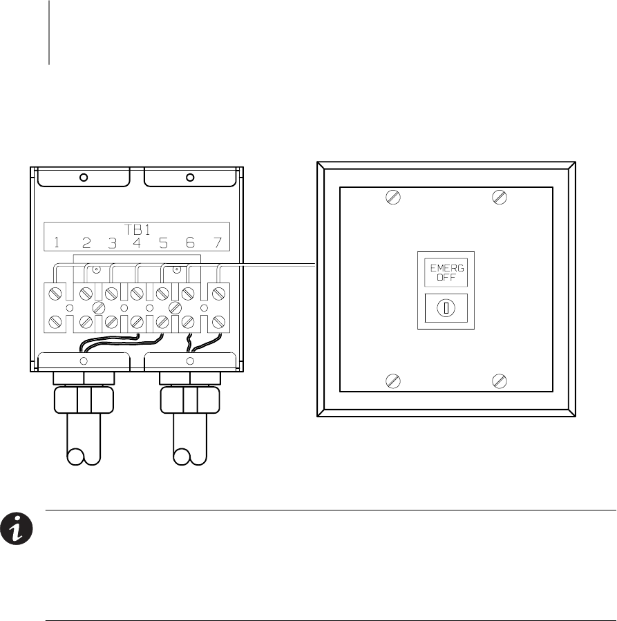
5-1
EATON Powerware®9390 UPS (100–160 kVA) Installation and Operation Manual S164201604 Rev B powerware.com
Chapter 5 Installing a Remote Emergency Power-off Switch
A latching-type REPO switch can be used in an emergency to shut down the UPS and
remove power to the critical load from a location away from where the UPS is installed.
Figure 5-1 shows a REPO switch.
EMERGENCY OFF
UNINTERRUPTIBLE POWER SYSTEM
To UPS To Other Equipment
Figure 5-1. REPO Switch
NOTE When installing the REPO switch, you must install conduit between the device
and the UPS cabinet for wiring the switch.
NOTE Remove the UPS cabinet top or bottom conduit landing plate to punch conduit
holes (see Drawing 164201604-6 on page A-27).
NOTE The REPO switch must be a latching-type switch with a dedicated circuit.
1. Securely mount the REPO station. Recommended locations include operator’s
consoles or near exit doors. See Drawing 164201604-10 on page A-50 for
enclosure dimensions and wiring knockouts.
2. Verify the UPS system is turned off and all power sources are removed. See
Chapter 10, “UPS Operating Instructions” for shutdown instructions.
3. If not already open, unfasten the front door latch and swing the door open.
4. If not already removed, remove the doors. Remove the retaining screws located
inside each door at the top and bottom hinge pivot points, then lift the door off.
Retain the hardware for later use.
5. Remove the screws securing the control panel door and swing the door open.
Retain the hardware for later use.
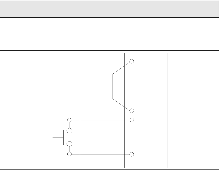
Installing a Remote Emergency Power-off Switch
5-2 EATON Powerware®9390 UPS (100–160 kVA) Installation and Operation Manual S164201604 Rev B powerware.com
6. Remove the screws securing the internal panel covering the TB1 and TB2 terminal
blocks at the top of the UPS cabinet (see Drawing 164201604-8 starting on
page A-33).
7. If installing interface wiring from the bottom of the cabinet, proceed to Step 8;
otherwise, proceed to Step 10.
8. Remove the screws securing the top internal safety shield panel and open the
panel to gain access to the bottom wiring entry.
9. Remove the screws securing the bottom internal safety shield panel and remove
the panel to gain access to the bottom conduit landing plate.
10. To locate the appropriate terminals and review the wiring and termination
requirements, see Figure 5-1 and Drawing 164201604-8 starting on page A-33.
11. Route and connect the wiring as shown in Table 5-1 and Table 5-2.
12. If a normally-closed EPO switch is not used, ensure a jumper wire is connected
between pins 1 and 2 on UPS TB1.
Table 5-1. REPO Wire Terminations
From REPO Station(s) To Customer Interface
Terminal Board TB1 in UPS Cabinet
Remarks
TB1-4 TB-3 Twisted Wires (2)
14–22 AWG
TB1-5 TB-4
Table 5-2. REPO
5 4 (COMMON)
1(NC)
UPS TB1
REPO
Switch
(NO)
Twisted
Wires
2 (COMMON)
3(NO)
4
(LATCHING-TYPE
SWITCH ONLY)
REPO switch rating is 24 Vdc. 1A minimum if supplied by customer.
NOTE The REPO switch must be a latching-type switch with a dedicated circuit.
Installing a Remote Emergency Power-off Switch
5-3
EATON Powerware®9390 UPS (100–160 kVA) Installation and Operation Manual S164201604 Rev B powerware.com
13. If you are installing multiple REPO stations, wire additional stations in parallel with
the first REPO.
14. If required, install wiring from the REPO station to trip circuitry of upstream
protective devices. A normally-open (NO) contact is provided between terminals 6
and 7 of REPO, as shown in Figure 5-1. REPO switch wiring must be in accordance
with UL Class II requirements.
15. When all wiring is complete, reinstall the safety shield panels removed in the
previous steps.
16. Close the control panel door and secure with the retained hardware.
17. Reinstall the doors removed in Step 4 and secure with the retained hardware.
18. Close the doors and secure the latch.
Installing a Remote Emergency Power-off Switch
5-4 EATON Powerware®9390 UPS (100–160 kVA) Installation and Operation Manual S164201604 Rev B powerware.com
This page intentionally left blank.
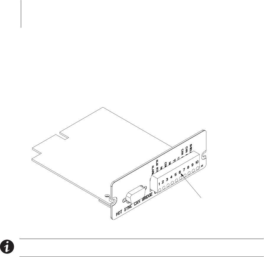
6-1
EATON Powerware®9390 UPS (100–160 kVA) Installation and Operation Manual S164201604 Rev B powerware.com
Chapter 6 Installing Options and Accessories
6.1 Installing a Powerware Hot Sync CAN Bridge Card
As an option, a Powerware Hot Sync Computer Area Network Bridge Card shown in
Figure 6-1, can be installed to provide connectivity for operational mode control and
metering of a parallel system at any UPM in the system. In addition, this card can be used
to connect optional system monitoring devices, such as a Remote Monitor Panel II, a Relay
Interface Module II, or a Supervisory Contact Module II to the UPS.
Plug-in Terminal
Block J3
Figure 6-1. Powerware Hot Sync CAN Bridge Card
NOTE Only one Powerware Hot Sync CAN Bridge Card can be installed in the UPS.
Multiple CAN cards are not supported and will cause system conflicts.
1. Verify the UPS system is turned off and all power sources are removed. See
Chapter 10, “UPS Operating Instructions,” for shutdown instructions.
2. If not already open, unfasten the front door latch and swing the door open.
3. Install the Powerware Hot Sync CAN Bridge Card into an open X-Slot on the front
of the UPS. Remove the X-Slot cover panel to gain access to the X-Slot. See
Drawing 164201604-8 starting on page A-33 for location of the X-Slot
communication bay.

Installing Options and Accessories
6-2 EATON Powerware®9390 UPS (100–160 kVA) Installation and Operation Manual S164201604 Rev B powerware.com
4. Install wiring from the Powerware Hot Sync CAN Bridge Card in accordance with
the instructions listed below:
쑺Parallel system wiring (see paragraph 6.2)
쑺RMP II wiring (see paragraph 6.3)
쑺RIM II (see paragraph 6.4)
쑺SCM II (see paragraph 6.5)
6.2 Installing Parallel System Control Wiring
NOTE When installing external wiring to the X-Slot CAN card, conduit must be
installed to the UPS cabinet. When installing internal wiring to the X-Slot CAN card
terminals, route the wiring through the internal opening in the X-Slot communication
bay.
NOTE When installing interface wiring for the parallel system pull chain, conduit
must be installed between UPMs.
To install parallel system control wiring, perform the following procedure:
1. Verify the UPS system is turned off and all power sources are removed. See
Chapter 10, “UPS Operating Instructions,” for shutdown instructions.
2. Perform the procedure listed in paragraph 6.1.
3. If not already removed, remove the doors. Remove the retaining screws located
inside each door at the top and bottom hinge pivot points, then lift the door off.
Retain the hardware for later use.
4. Remove the screws securing the control panel door and swing the door open.
Retain the hardware for later use.
5. Remove the screws securing the top internal safety shield panel. Remove the panel
to gain access to the TB1 and TB2 terminal blocks, X-Slot communication bays,
and the top conduit landing plate (see Drawing 164201604-8 starting on
page A-33). Retain the hardware for later use.
6. If installing interface wiring from the bottom of the cabinet, proceed to Step 7;
otherwise, proceed to Step 8.
7. Remove the screws securing the bottom internal safety shield panel and remove
the panel to gain access to the bottom conduit landing plate.
8. Remove the X-Slot conduit landing plate from the UPS cabinet to drill or punch
conduit holes (see Drawing 164201604-6 on page A-27).
9. Reinstall the conduit landing plate and install the conduit.
10. Install CAN wiring between UPMs. See Drawing 164201604-8 starting on page A-33
for Powerware Hot Sync CAN Bridge Card location, terminal location, and wiring
information.

Installing Options and Accessories
6-3
EATON Powerware®9390 UPS (100–160 kVA) Installation and Operation Manual S164201604 Rev B powerware.com
11. Install parallel system backup control (pull chain) wiring between UPMs. See
Drawing 164201604-8 starting on page A-33 for terminal locations and wiring
information.
12. Install parallel system backup control (pull chain) wiring between the bypass relay
and building alarm 2. See Drawing 164201604-8 starting on page A-33 for terminal
locations and wiring information.
NOTE Setup of the Powerware Hot Sync CAN Bridge Card for parallel operation must
be performed by an authorized Eaton Customer Service Engineer. Contact service to
schedule a date.
13. When all wiring is complete, reinstall the safety shield panels removed in previous
steps. Secure with the retained hardware.
14. Close the control panel door and secure with the retained hardware.
15. Reinstall the doors removed previously and secure with the retained hardware.
16. Close the doors and secure the latch.
6.3 Installing a Remote Monitor Panel II
To install RMP II wiring, perform the following procedure:
1. Verify the UPS system is turned off and all power sources are removed. See
Chapter 10, “UPS Operating Instructions,” for shutdown instructions.
2. Perform the procedure listed in paragraph 6.1.
NOTE If mounting to a hollow wall, secure the enclosure to a wood or metal stud within
the wall. Do not use hollow wall anchors.
3. Securely mount the RMP II at the desired location. See drawing 164201604-11 on
page A-51 for mounting hole locations.
NOTE When installing signal wiring for CAN card J3 terminals, conduit must be
installed between the device and the UPS cabinet.
NOTE Remove the UPS cabinet top or bottom conduit landing plate to drill or punch
conduit holes (see Drawing 164201604-6 on page A-27).
4. Remove the X-Slot conduit landing plate from the UPS cabinet to drill or punch
conduit holes (see Drawing 164201604-6 on page A-27).
5. Reinstall the conduit landing plate.
6. Install conduit between the UPS and RMP II. See Appendix A for UPS cabinet and
RMP II wiring access information.

Installing Options and Accessories
6-4 EATON Powerware®9390 UPS (100–160 kVA) Installation and Operation Manual S164201604 Rev B powerware.com
7. Install wiring between the UPS and RMP II. See Drawing 164201604-8 starting on
page A-33 for Powerware Hot Sync CAN Bridge Card and RMP II location, terminal
location, and wiring information.
NOTE 120 Vac for the RMP II should be supplied from the critical bus by facility
planners or the customer.
8. Install 120 Vac power wiring from the critical bus to the RMP II. See Drawing
164201604-8 starting on page A-33 for terminal location and wiring information.
NOTE Setup of the Powerware Hot Sync CAN Bridge Card must be performed by an
authorized Eaton Customer Service Engineer. Contact service to schedule a date.
9. To check the operation of the RMP II, ensure that the UPS is supplying the load via
inverter or bypass. If the indicators on the RMP II show the appropriate status,
then it is operating correctly.
If the communication link between the UPS and the RMP II is not present, the
RMP II performs a self-test (all indicators flash and the horn beeps at one-second
intervals). If the self-test occurs, check all harness connectors and the fuse for
proper seating. If all connections are secure but the RMP II continues to self-test,
replace the fuse with the spare included in the hardware kit. If a fuse replacement
does not correct the problem, contact your Eaton service representative for
verification that the RMP II is working correctly.
10. To test the indicator lamps, press and hold the horn silence pushbutton for
3 seconds. All lamps should illuminate, and the horn sounds continuously until you
release the pushbutton.
6.4 Installing a Relay Interface Module II
To install RIM II wiring, perform the following procedure:
1. Verify the UPS system is turned off and all power sources are removed. See
Chapter 10, “UPS Operating Instructions,” for shutdown instructions.
2. Perform the procedure listed in paragraph 6.1.
NOTE If mounting to a hollow wall, secure the enclosure to a wood or metal stud within
the wall. Do not use hollow wall anchors.
3. Securely mount the RIM II at the desired location. See drawing 164201604-12 for
mounting hole locations.

Installing Options and Accessories
6-5
EATON Powerware®9390 UPS (100–160 kVA) Installation and Operation Manual S164201604 Rev B powerware.com
NOTE When installing signal wiring for CAN card J3 terminals, conduit must be
installed between the device and the UPS cabinet.
NOTE Remove the UPS cabinet top or bottom conduit landing plate to drill or punch
conduit holes (see Drawing 164201604-6 on page A-27).
4. Remove the X-Slot conduit landing plate from the UPS cabinet to drill or punch
conduit holes (see Drawing 164201604-6 on page A-27).
5. Reinstall the conduit landing plate.
6. Install conduit between the UPS and RIM II. See Appendix A for UPS cabinet and
RIM II wiring access information.
7. Install wiring between the UPS and RIM II. See Drawing 164201604-8 starting on
page A-33 for Powerware Hot Sync CAN Bridge Card and RIM II location, terminal
location, and wiring information.
NOTE 120 Vac for the RIM II should be supplied from the critical bus by facility
planners or the customer.
8. Install 120 Vac power wiring from the critical bus to the RIM II. See Drawing
164201604-8 starting on page A-33 for terminal location and wiring information.
NOTE Setup of the Powerware Hot Sync CAN Bridge Card must be performed by an
authorized Eaton Customer Service Engineer. Contact service to schedule a date.
9. Contact your Eaton service representative for verification and testing of the RIM II
and its connections prior to making connections with J1 through J4 (see Table 6-1
and Drawing 164201604-12 on page A-52).
You can order interface cables separately for connecting to the 15-Pin D-Sub
Connectors.
Table 6-1. J1 through J4 Interface Connectors
Status J1 through J4 Description
UPS AVAILABLE Pins 1 and 12 Contacts are closed when the UPS is offline.
UPS OFFLINE Pins 3 and 13 Contacts are closed when the UPS is operating in
Normal mode.
BATTERY WEAK Pins 5 and 14 Contacts are closed when approximately two minutes of
battery time is remaining before the critical load is lost.
UTILITY FAILURE Pins 6 and 15 Contacts are closed when Utility Failure is detected.

Installing Options and Accessories
6-6 EATON Powerware®9390 UPS (100–160 kVA) Installation and Operation Manual S164201604 Rev B powerware.com
6.5 Installing a Supervisory Contact Module II
To install SCM II wiring, perform the following procedure:
1. Verify the UPS system is turned off and all power sources are removed. See
Chapter 10, “UPS Operating Instructions,” for shutdown instructions.
2. Perform the procedure listed in paragraph 6.1.
NOTE If mounting to a hollow wall, secure the enclosure to a wood or metal stud within
the wall. Do not use hollow wall anchors.
3. Securely mount the SCM II at the desired location. See drawing 164201604-13 on
page A-54 for mounting hole locations.
NOTE When installing signal wiring for CAN card J3 terminals, conduit must be
installed between the device and the UPS cabinet.
NOTE Remove the UPS cabinet top or bottom conduit landing plate to drill or punch
conduit holes (see Drawing 164201604-6 on page A-27).
4. Remove the X-Slot conduit landing plate from the UPS cabinet to drill or punch
conduit holes (see Drawing 164201604-6 on page A-27).
5. Reinstall the conduit landing plate.
6. Install conduit between the UPS and SCM II. See Appendix A for UPS cabinet and
SCM II wiring access information.
7. Install wiring between the UPS and SCM II. See Drawing 164201604-8 starting on
page A-33 for Powerware Hot Sync CAN Bridge Card and SCM II location, terminal
location, and wiring information.
NOTE 120 Vac for the SCM II should be supplied from the critical bus by facility
planners or the customer.
8. Install 120 Vac power wiring from the critical bus to the SCM II. See Drawing
164201604-8 starting on page A-33 for terminal location and wiring information.
NOTE Setup of the Powerware Hot Sync CAN Bridge Card must be performed by an
authorized Eaton Customer Service Engineer. Contact service to schedule a date.
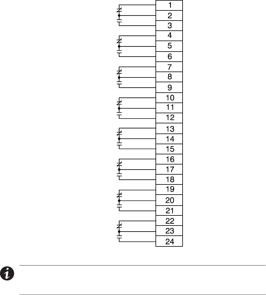
Installing Options and Accessories
6-7
EATON Powerware®9390 UPS (100–160 kVA) Installation and Operation Manual S164201604 Rev B powerware.com
9. Install wiring between the SCM II terminal block TB2 and the monitoring
equipment. See Figure 6-2 for terminal assignments and Drawing 164201604-8 on
page A-33 for terminal block location.
System Normal
No Redundancy
On Generator
Bypass Not
Available
On Battery
UPS Alarm
On Bypass
Shutdown
Imminent
TB2
Figure 6-2. Supervisory Contact Module II TB2
NOTE Supervisory contacts are rated at 2.0A at 28 Vdc or 120 Vac and 0.15A at 115 Vdc.
NOTE Supervisory contacts require an external power supply. Internal 24 Vdc is not
capable of supplying contact current.
Installing Options and Accessories
6-8 EATON Powerware®9390 UPS (100–160 kVA) Installation and Operation Manual S164201604 Rev B powerware.com
This page intentionally left blank.

6-9
EATON Powerware®9390 UPS (100–160 kVA) Installation and Operation Manual S164201604 Rev B powerware.com
Section II Operation

6-10 EATON Powerware®9390 UPS (100–160 kVA) Installation and Operation Manual S164201604 Rev B powerware.com
This page intentionally left blank.
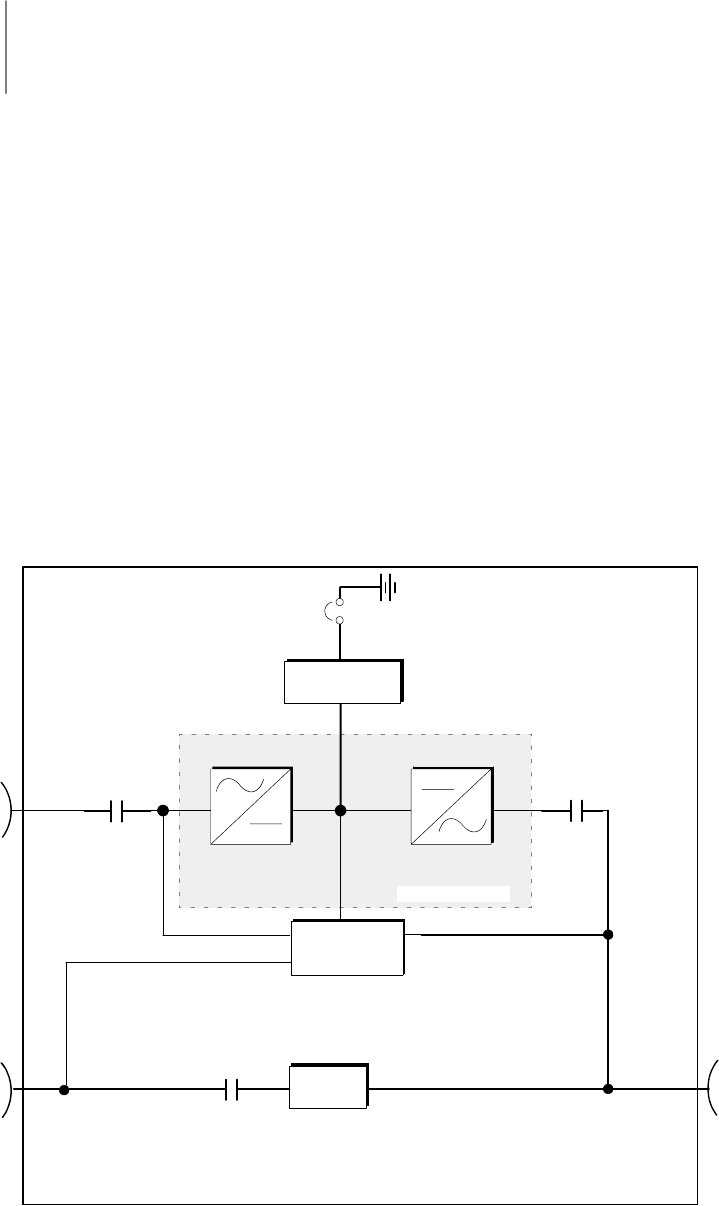
7-1
EATON Powerware®9390 UPS (100–160 kVA) Installation and Operation Manual S164201604 Rev B powerware.com
Chapter 7 Understanding UPS Operation
7.1 Looking Inside the UPS System
The Powerware 9390 UPS is a continuous-duty, solid-state, transformerless (at 208 and
480 Vac), three-phase, true online system that provides conditioned and uninterruptible
AC power to the UPS system’s output. The UPS supports process control, data processing,
telecommunications/PBX, research, and non-patient medical equipment. The Powerware
9390 UPS maintains power to the critical loads during commercial electrical power
brownout, blackout, overvoltage, undervoltage, and out-of-tolerance frequency conditions.
The basic system consists of a rectifier, battery converter, inverter, monitoring/operation
control panel, integrated communication server, and digital signal processor (DSP) logic.
In this manual, the power required by your equipment is called the critical load.TheUPS
supplies the critical load with conditioned power that is synchronized with your utility
power. Figure 7-1 shows the main elements of the UPS system.
Output
Contactor
K3
Battery
Battery
Breaker
Battery
Converter
Input
Contactor
K1
AC Input to
Rectifier/
Charger
AC Input to
Bypass
Backfeed
Protection
Contactor
K5
Power Module
InverterRectifier
Digital
Metering
Static
Switch
AC Output
to Critical
Load
UPS Cabinet
Figure 7-1. Main Elements of the UPS System
Understanding UPS Operation
7-2 EATON Powerware®9390 UPS (100–160 kVA) Installation and Operation Manual S164201604 Rev B powerware.com
If utility power is interrupted or falls outside the parameters specified in Chapter 15,
“Product Specifications,” the UPS uses a backup battery supply to maintain power to the
critical load for a specified period of time or until the utility power returns. For extended
power outages, the UPS allows you to either transfer to an alternative power system (such
as a generator) or shut down your critical load in an orderly manner.
The emergency bypass consists of a continuous-duty static switch and backfeed protection
contactor K5. The backfeed protection contactor is located in series with the static switch.
For manual transfers to bypass, the static switch is also used. The static switch is armed and
ready during both types of transfers.
The operation of the UPS system is described in greater detail in the following paragraphs.
TheUPSmodulemaybeconfiguredforstandalone,singlemodule,ReverseTransfer(RT)
operation or multiple module, parallel redundant and/or parallel capacity operation (see
paragraphs 7.2 and 7.3).
7.2 Single Module Reverse Transfer (RT)
Asinglemoduleoperatesindependentlytosupportanappliedloadfromtheinverter,
providing conditioned and uninterruptible AC power to the critical load from the output of
the module. During an outage, the inverter continues to operate, supporting power to the
load from the battery supply. If the unit requires service, applied loads are transferred to
the internal bypass, continuous-duty static switch either automatically or manually. With
the exception of a battery cabinet, no other cabinets or equipment are required for the
single module to successfully support its applied loads.
7.2.1 Single Module RT Modes
The Powerware 9390 UPS supports a critical load in three different modes of operation.
The UPS can automatically use all three modes, as required. The standard operation
modes are:
쑺In Normal mode, the critical load is supplied by the inverter, which derives its power
from rectified utility AC power. In this mode, the battery charger also provides charging
current for the battery, if needed.
쑺In Battery mode, the battery provides DC power, which maintains inverter operation.
The battery supports the critical load.
쑺In Bypass mode, the critical load is directly supported by utility power.
Understanding UPS Operation
7-3
EATON Powerware®9390 UPS (100–160 kVA) Installation and Operation Manual S164201604 Rev B powerware.com
The UPS continually monitors itself and the incoming utility power, and automatically
switches between these modes as required, without operator intervention. The
sophisticated detection and switching logic inside the UPS ensures that operating mode
changes are automatic and transparent to the critical load, while internal monitoring
systems indicate the current mode of operation. The UPS switches operating modes in
response to these system events:
쑺Acommand is an intervention that is externally initiated by an operator or by some site
action. A command causes the UPS to switch operating modes; it usually does not
require any further action.
쑺Anotice is a minor system event that may or may not require attention.
쑺An alarm is a system event that requires immediate operator intervention.
System events, alarm horns, and indicator lights are described in Chapter 12, “Responding
to System Events.”
The following paragraphs describe the differences in the three UPS operating modes, using
block diagrams to show the power flow during each mode of operation.
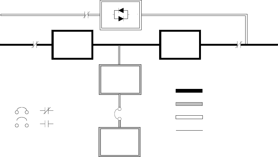
Understanding UPS Operation
7-4 EATON Powerware®9390 UPS (100–160 kVA) Installation and Operation Manual S164201604 Rev B powerware.com
7.2.2 Normal Mode – RT
Figure 7-2 shows the path of electrical power through the UPS system when the UPS is
operating in Normal mode.
Static
Switch
K5
Rectifier Inverter
K1 K3
Battery
Converter
Battery
Battery
Breaker
Main Power Flow
Trickle Current
Energized
De-Energized
Closed
Open
Breakers Contactors
Static
Switch
K5
Rectifier Inverter
K1 K3
Battery
Converter
Battery
Battery
Breaker
Main Power Flow
Trickle Current
Energized
De-Energized
Closed
Open
Breakers Contactors
Figure 7-2. Path of Current Through the UPS in Normal Mode – RT
During normal UPS operation, power for the system is derived from a utility input source
through the rectifier input contactor K1. The front panel displays “Normal,” indicating the
incoming power is within voltage and frequency acceptance windows. Three-phase AC
input power is converted to DC using IGBT devices to produce a regulated DC voltage to
the inverter. The battery is charged directly from the regulated rectifier output through a
buck or boost DC converter, depending on whether the system is 208V or 480V and the
size of the battery string attached to the unit.
The battery converter derives its input from the regulated DC output of the rectifier and
provides either a boosted or bucked regulated DC voltage charge current to the battery.
The UPS monitors the battery charge condition and reports the status on the control panel.
The battery is always connected to the UPS and ready to support the inverter should the
utility input become unavailable.
Understanding UPS Operation
7-5
EATON Powerware®9390 UPS (100–160 kVA) Installation and Operation Manual S164201604 Rev B powerware.com
The neutral from the system input is connected to the neutral regulator in the DC
capacitors. The output neutral of the system is connected with the required neutral
supplied at the utility bypass input and should never be bonded to ground at the module’s
output.
The inverter produces a three-phase AC output to a customer’s load without the use of a
transformer. The inverter derives regulated DC from the rectifier and uses IGBT devices
and pulse-width modulation (PWM) to produce a regulated and filtered AC output. The AC
output of the inverter is delivered to the system output through the output contactor K3.
If the utility AC power is interrupted or is out of specification, the UPS automatically
switches to Battery mode to support the critical load without interruption. When utility
power returns, the UPS returns to Normal mode.
IftheUPSbecomesoverloadedorunavailable,theUPSswitchestoBypassmode.TheUPS
automatically returns to Normal mode when the overload condition is cleared and system
operation is restored within specified limits.
If the UPS suffers an internal failure, it switches automatically to Bypass mode and remains
in that mode until the failure is corrected and the UPS is back in service.
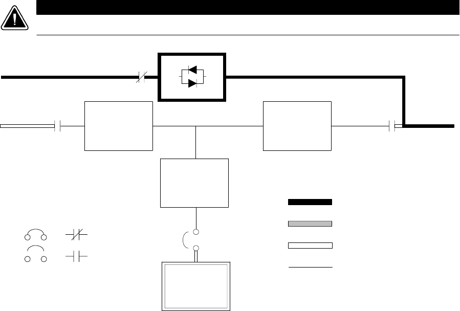
Understanding UPS Operation
7-6 EATON Powerware®9390 UPS (100–160 kVA) Installation and Operation Manual S164201604 Rev B powerware.com
7.2.3 Bypass Mode – RT
The UPS automatically switches to Bypass mode if it detects an overload, load fault, or
internalfailure.ThebypasssourcesuppliesthecommercialACpowertotheloaddirectly.
Figure 7-3 shows the path of electrical power through the UPS system when operating in
Bypass mode.
CAUTION
The critical load is not protected while the UPS is in Bypass mode.
Static
Switch
K5
Rectifier Inverter
K1 K3
Battery
Converter
Battery
Battery
Breaker
Main Power Flow
Trickle Current
Energized
De-Energized
Closed
Open
Breakers Contactors
Figure 7-3. Path of Current Through the UPS in Bypass Mode – RT
In Bypass mode, the output of the system is provided with three-phase AC power directly
from the system input. While in this mode, the output of the system is not protected from
voltage or frequency fluctuations or power outages from the source. Some power line
filtering and spike protection is provided to the load but no active power conditioning or
battery support is available to the output of the system in the Bypass mode of operation.
Theinternalbypassiscomprisedofasolid-state, silicon-controlled rectifier (SCR) static
switch (SSW) and a backfeed protection contactor K5. The static switch is rated as a
continuous-duty device that is used anytime the inverter is unable to support the applied
load. The static switch is wired in series with the backfeed protection contactor, and
together they are wired in parallel with the rectifier and inverter. The static switch, being
an electronically-controlled device, can be turned on immediately to pick up the load from
the inverter while the inverter output contactor K3 opens to isolates the inverter. The
backfeed protection contactor is normally always closed, ready to support the static switch
unless the bypass input source becomes unavailable.
Understanding UPS Operation
7-7
EATON Powerware®9390 UPS (100–160 kVA) Installation and Operation Manual S164201604 Rev B powerware.com
During an outage, the UPS prohibits transfers to bypass and provides upstream protection.
The backfeed protection contactor is opened, preventing system output voltage from
bleeding across the static switch snubber components to the bypass input source.
To ensure the load remains energized, the UPS automatically transfers the output to the
internal bypass when one of these abnormal conditions occur: the output of the system
exceeds acceptable voltage and frequency tolerances, the system is overloaded, or the
inverter fails. The transfer is initiated by turning on the static switch and opening the
output contactor K3, also called a Make-Before-Break transfer. The transfer occurs in less
than 4 mS (quarter cycle) to ensure that the output load is not interrupted. The static
switch remains on until either the inverter is able to support the system output or the unit
is placed into a maintenance position where repairs can be made.
If the UPS initiates its own transfer to bypass for any reason other than operator
intervention, the UPS attempts to restart the inverter (if not running already) and attempts
a transfer back online to support the output of the system. Three attempts are made
within ten minutes to return the inverter online automatically before the UPS locks out any
further attempts. After three attempts, the UPS remains in bypass and an alarm condition
is enunciated. The UPS can also be transferred to bypass using the front panel controls.
Bypass mode is a normal operating mode, not an alarm condition. However, if the UPS is
unable to return to Normal mode following an automatic transfer to Bypass mode, an
alarm condition is recorded.
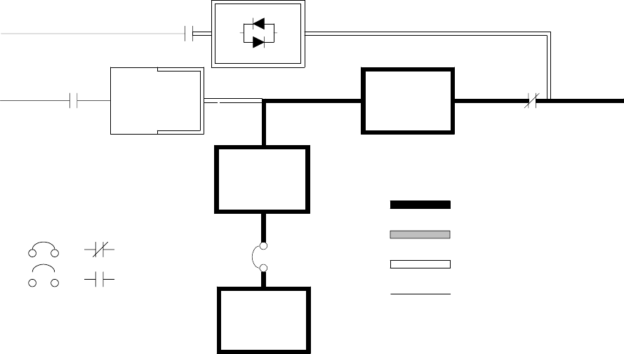
Understanding UPS Operation
7-8 EATON Powerware®9390 UPS (100–160 kVA) Installation and Operation Manual S164201604 Rev B powerware.com
7.2.4 Battery Mode – RT
The UPS automatically transfers to Battery mode if a utility power outage occurs, or if the
utility power does not conform to specified parameters. In Battery mode, the battery
provides emergency DC power that the inverter converts to AC power.
Figure 7-4 shows the path of electrical power through the UPS system when operating in
Battery mode.
Static
Switch
K5
Rectifier Inverter
K1 K3
Battery
Converter
Battery
CB2
Main Power Flow
Trickle Current
Energized
De-Energized
Closed
Open
Breakers Contactors
Figure 7-4. Path of Current Through the UPS in Battery Mode – RT
During a utility power failure, the rectifier no longer has an AC utility source from which to
supply the DC output current required to support the inverter. The input contactor K1
opens and the battery instantaneously supplies energy to the battery converter. The
converter either bucks or boosts the voltage so that the inverter can support the
customer’s load without interruption. If bypass is common with the rectifier input, the
backfeed protection contactor K5 also opens. The opening of contactors K1 and K5
prevent system voltages from bleeding backwards through the static switch and rectifier
snubber components and re-entering the input source.
While in Battery mode, the UPS sounds an audible horn, illuminates a visual indicator lamp
on the front panel (System Normal, On Battery), and creates an entry into the alarm event
history. As the battery discharges, the converter and inverter constantly make minute
adjustments to maintain a steady output. The UPS remains in this operating mode until the
input power to the rectifier is again within the specified voltage or frequency acceptance
windows.
Understanding UPS Operation
7-9
EATON Powerware®9390 UPS (100–160 kVA) Installation and Operation Manual S164201604 Rev B powerware.com
If the input power fails to return or is not within the acceptance windows required for
normal operation, the battery continues discharging until a DC voltage level is reached
where the inverter output can no longer support the connected loads. When this event
occurs, the UPS issues another set of audible and visual alarms indicating SHUTDOWN
IMMINENT. Unless the rectifier has a valid AC input soon, the output can be supported for
only two minutes before the output of the system shuts down. If the bypass source is
available, the UPS transfers to bypass instead of shutting down.
If at any time during the battery discharge the input power becomes available again,
contactors K1 and K5 close and the rectifier begins to supply DC current to the converter
and inverter. At this point, the unit returns to Normal mode. Depending on the total load
and the duration of the battery discharge, battery current limit alarms may be seen for a
short time due to the current required to recharge the battery.
The system’s total operating time on battery depends on many factors. Some factors that
affect battery support times are battery type and capacity, number of parallel strings,
environmental temperatures, age of the battery, and fluctuations in load demand during
the discharge. The greater the load, the less support time the battery has. Decreasing the
load generally increases the battery support time.
7.3 Multiple Module Parallel System
Parallel operation extends the normal operation of Powerware 9390 UPS units by offering
increased capacity and/or redundant capability. The parallel system continues to maintain
power to the critical loads during commercial electrical power brownout, blackout,
overvoltage, undervoltage, and out-of-tolerance frequency conditions. See Drawing
164201604-4, sheets 4 of 6, 5 of 6, and 6 of 6 in Appendix A, for a detailed relationship of
the parallel system.
The output of the system is normally supplied by several uninterruptible power modules.
Multiple UPMs are connected with their outputs in parallel (tied together) to provide a
load level greater than the rating of one UPM and/or for redundancy. The paralleled UPMs
supply the output load with protected power as long as the load does not exceed the
combined rating of the paralleled UPMs.
The power system is redundant as long as one of the UPMs can be disconnected from the
output bus and the remaining UPMs can continue to supply power to the load without
exceeding their ratings.
When the load is being supplied by the UPMs, the system output bus is continuously
monitored for an overvoltage or undervoltage condition. If an out of limits condition is
detected, the paralleled UPMs transfer the load to bypass using the UPM static switches.
Communication is required between the UPMs for system metering and mode control.
System level communication and control are accomplished using a Computer Area
Network. A single building alarm in each UPM, connected to the other UPMs in parallel,
and tied to the bypass contactor auxiliary contacts in each UPM are used for a secondary
communication path. This arrangement ensures bypass control even if the CAN bus is lost.
Understanding UPS Operation
7-10 EATON Powerware®9390 UPS (100–160 kVA) Installation and Operation Manual S164201604 Rev B powerware.com
Up to four units can be paralleled for redundancy or capacity without any additional
cabinets.
The system is paralleled for redundancy (1+1) in a system where two UPMs are paralleled
together and the load is less than the supporting capability of one of the UPMs. The system
is paralleled for capacity (2+0) if both UPMs in a system are required to support the load.
A parallel capacity system can also be redundant (2+1), as long as there is always one or
more UPMs online than required to support the load.
7.3.1 Multiple Module Parallel System Modes
Similar to the single module system, the Powerware 9390 UPS parallel system supports a
critical load in three different modes of operation. The standard operation modes are:
쑺In Normal mode, the paralleled UPMs supply the critical load with clean, filtered power.
Each UPM battery charger also provides charging current for the battery if needed.
쑺In Battery mode, the battery provides DC power, which maintains UPM operation. The
UPM batteries support the critical load.
쑺In Bypass mode, the critical load is directly supported by utility power through the
continuous-duty static bypass switch in each UPM.
The UPMs continually monitor themselves and the incoming utility power, and
automatically switch between these modes as required, without operator intervention,
except when manually switching to Bypass mode. The sophisticated detection and
switching logic inside the UPMs ensures that operating mode changes are automatic and
transparent to the critical load, while internal monitoring systems indicate the current
mode of operation. The UPMs switch operating modes in response to these system events:
쑺Acommand is an intervention that is externally initiated by an operator or by some site
action. A command causes the UPMs to switch operating modes; it usually does not
require any further action.
쑺Anotice is a minor system event that may or may not require attention.
쑺An alarm is a system event that requires immediate intervention.
System events, alarm horns, and indicator lights are described in Chapter 12, “Responding
to System Events.”
To assist in developing an understanding of the parallel system modes of operation, review
and understand thoroughly the single module modes of operation.
The following paragraphs describe the differences in the three parallel system operating
modes, using block diagrams to show the power flow during each mode of operation.
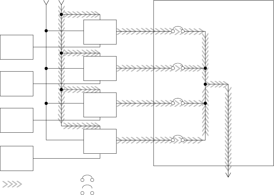
Understanding UPS Operation
7-11
EATON Powerware®9390 UPS (100–160 kVA) Installation and Operation Manual S164201604 Rev B powerware.com
7.3.2 Normal Mode – Parallel
In Normal mode, utility AC power is supplied to the UPMs. Each UPM then conditions the
incoming AC power and provides clean, regulated AC power to either a module tie cabinet
or distribution panel for parallel systems up tofourmodules.Theappliedloadisequally
shared among the available UPMs in the system.
Figure 7-5 shows the path of electrical power through the parallel system when operating
in Normal mode.
Main Power Flow
UPM 1
UPM 2
UPM 3
UPM 4
Output to
Critical
Load
Battery
UPM Input Module Tie Cabinet
UPM 1 Output
Bypass Input
UPM 2 Output
UPM 3 Output
UPM 4 Output
Battery
Battery
Battery
Closed
Open
Breakers
Figure 7-5. Path of Current through the UPMs in Normal Mode – Parallel
If the utility AC power is interrupted or is out of specification, the UPMs automatically
switch to Battery mode to support the critical load without interruption. When utility
power returns, the UPMs return to Normal mode.
IftheUPMsbecomeoverloadedorunavailable,theparallelsystemswitchestoBypass
mode. The parallel system automatically returns to Normal mode when the overload
condition is cleared and system operation is restored within specified limits.
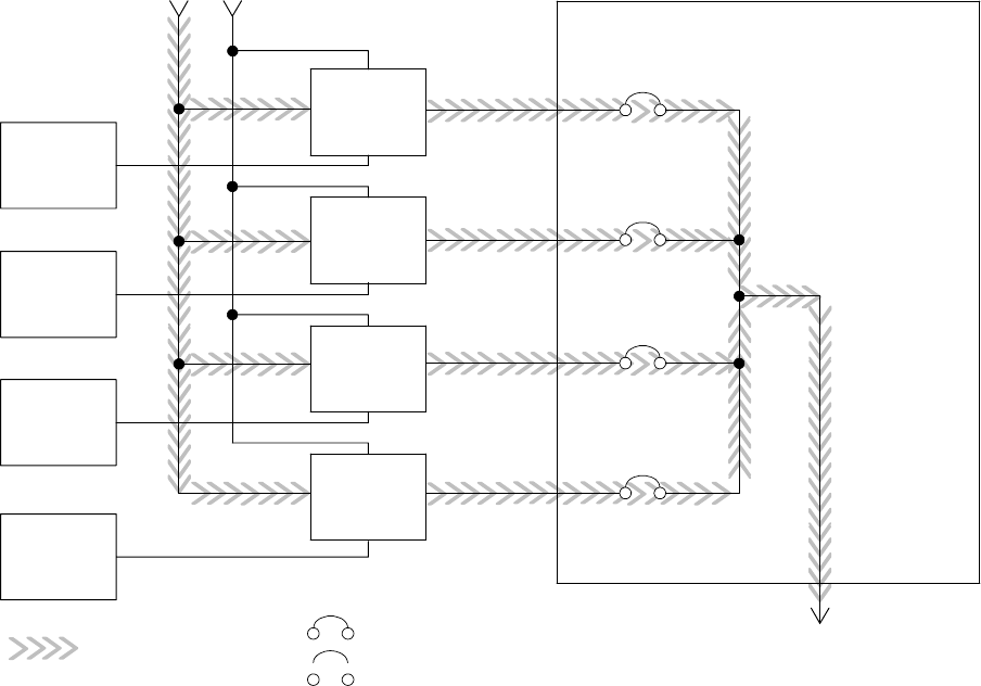
Understanding UPS Operation
7-12 EATON Powerware®9390 UPS (100–160 kVA) Installation and Operation Manual S164201604 Rev B powerware.com
7.3.3 Bypass Mode – Parallel
In Bypass mode, the output of the system is provided with three-phase AC power directly
from the bypass input. While in this mode, the output of the system is not protected from
fluctuations, spikes, or power outages from the source. No power filtering, conditioning, or
battery support is available to the output of the system in the Bypass mode of operation.
The parallel system automatically switches to Bypass mode if it detects a UPM overload,
UPMs unavailable, load fault, or internal failure.
Figure 7-6 shows the path of electrical power through the parallel system when operating
in Bypass mode.
Main Power Flow
UPM 1
UPM 2
UPM 3
UPM 4
Output to
Critical
Load
Battery
UPM Input Module Tie Cabinet
UPM 1 Output
Bypass Input
UPM 2 Output
UPM 3 Output
UPM 4 Output
Battery
Battery
Battery
Closed
Open
Breakers
Figure 7-6. Path of Current through the UPMs in Bypass Mode – Parallel
In a parallel redundant or capacity type system, each module operates similar to a single
module, but in parallel with each other. The bypass source for the load is derived from the
bypass input of one, two, three, or four modules, depending on the system configuration
through the internal continuous-duty static switches. If a module is taken offline, the other
modulesremainonlinetosupporttheload.Ifmoremodulesthancansupporttheload
must be taken offline, the load must be transferred to maintenance bypass or shut down.
Understanding UPS Operation
7-13
EATON Powerware®9390 UPS (100–160 kVA) Installation and Operation Manual S164201604 Rev B powerware.com
The parallel system can be transferred from Normal mode to Bypass mode manually.
However, the parallel system automatically switches to Bypass mode whenever the UPMs
can no longer supply the critical load. If the parallel system transfers to Bypass mode from
Normal mode due to an output voltage deviation, the parallel system automatically
attempts to return to Normal mode (up to three times within a 10-minute period). After
three transfer attempts or an overload, the system locks the critical load to the bypass
source and requires operator intervention to transfer.
Bypass mode is a normal operating mode, not an alarm condition. However, if the parallel
system is unable to return to Normal mode following an automatic transfer to Bypass
mode, an alarm condition is recorded.
Bypass may also be used when the modules in the system must be shut down to perform
routine maintenance or repairs.
In the Parallel Redundant (N + 1) arrangement, the continuous-duty static switch in each
module operates to support the applied loads on bypass. If both units are in NORMAL and
one unit trips offline, the remaining unit does not go to bypass as long as it has the
capacity to support the load.
In the Parallel Capacity (N + 0) arrangement, if one unit trips offline and goes to bypass,
the remaining units also go to bypass.
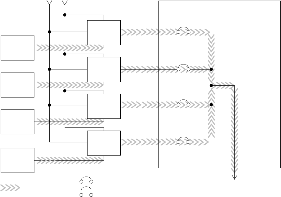
Understanding UPS Operation
7-14 EATON Powerware®9390 UPS (100–160 kVA) Installation and Operation Manual S164201604 Rev B powerware.com
7.3.4 Battery Mode – Parallel
The UPMs transfer to Battery mode automatically if a utility power outage occurs, or if the
utility power does not conform to specified parameters. In Battery mode, the battery
provides emergency DC power that the inverter converts to AC power.
Figure 7-7 shows the path of electrical power through the parallel system when operating
in Battery mode.
Main Power Flow
UPM 1
UPM 2
UPM 3
UPM 4
Output to
Critical
Load
Battery
UPM Input Module Tie Cabinet
UPM 1 Output
Bypass Input
UPM 2 Output
UPM 3 Output
UPM 4 Output
Battery
Battery
Battery
Closed
Open
Breakers
Figure 7-7. Path of Current through the UPMs in Battery Mode – Parallel
While in Battery mode, the UPMs sound an audible horn, illuminate a visual indicator lamp
on the front panel (System Normal, On Battery), and create an entry into the alarm event
history. As the battery discharges, the boost converter and inverter constantly make minute
adjustments maintaining a steady output. The UPMs remain in this operating mode until
the input power to the rectifier is again within the specified voltage or frequency
acceptance windows.
Understanding UPS Operation
7-15
EATON Powerware®9390 UPS (100–160 kVA) Installation and Operation Manual S164201604 Rev B powerware.com
If the input power fails to return or is not within the acceptance windows required for
normal operation, the battery continues discharging until a DC voltage level is reached
where the inverter output can no longer support the shared loads. When this event occurs
on each UPM, UPMs that are about to be shut down issue another set of audible and visual
alarms that indicate a two-minute SHUTDOWN IMMINENT warning. Unless the system has
a valid AC input soon, redundant UPMs begin shutting down until there are no longer
enough UPMs online to support the connected load. When this event occurs, the system
shutsdown.Ifthebypasssourceisavailable,thesystemtransferstobypassinsteadof
shutting down.
If at any time during the battery discharge the input power becomes available again, the
rectifier begins to supply DC current to the inverter. At this point, the unit returns to
Normal mode. If at any time during the battery discharge the AC input power becomes
available again, each rectifier turns on, assumes the inverter load from the batteries, and
begins recharging the batteries. Depending on the total load and the duration of the
battery discharge, battery and rectifier input current limit alarms may be seen for a short
time due to the current required to recharge the batteries.
7.4 Functional Description
The UPS is a true online double-conversion unit with a transformerless power train. A
high-frequency active rectifier powers a high-frequency three-phase inverter. The bypass
circuit uses a solid-state continuous-duty static switch. The UPS operates from battery
strings from 192 cells (384V) to 240 cells (480V).
7.4.1 Input Rectifier
The rectifier is a three-phase, high-frequency PWM, IGBT-based power conversion stage
that provides input power factor correction and low input current harmonic distortion. The
rectifier maintains a DC level that is optimized for maximum inverter efficiency. A
precharge system charges the energy storage elements in the power train prior to
energizing the rectifier.
7.4.2 Inverter
The inverter is a three-phase, high-frequency PWM, IGBT-based power conversion stage
that continuously supplies the critical load with high-quality AC power. The IGBTs are
modulated to maintain the highest efficiency.
7.4.3 Battery Charger and Advanced Battery Management
The charger is a high-frequency, IGBT-based power conversion stage. The UPS uses
Advanced Battery Management (ABM) technology, which essentially isolates the battery
from the electrical environment, except for periodic charging or reserve mode operation,
extending its life.
ABM extends battery life by keeping the batteries charged and performing periodic battery
testing.
Understanding UPS Operation
7-16 EATON Powerware®9390 UPS (100–160 kVA) Installation and Operation Manual S164201604 Rev B powerware.com
An ABM charging cycle starts with the charger driving the battery voltage, at maximum
current limit, to a battery charge level of 2.34 volts/cell. The time it takes for the voltage to
reach to the battery charge level is saved as the battery charge time. If the battery charge
time exceeds 100 hours, an alarm sounds.
As soon as a battery charge level of 2.34 volts/cell is reached, the battery is charged at a
float level of 2.31 volts/cell for 48 hours (battery float time) plus 150% of battery charge
time. Twenty-four hours into the float period, a series of battery tests are performed to
check the battery health. The float level charge continues after a successful test.
At initial startup, the battery run time on the front panel display indicates two minutes.
After the 24-hour float charging period and battery testing, the actual battery run time is
determined and the actual battery run time is displayed.
After the float period is completed, the charger is disconnected and the batteries are
allowed to rest for 672 hours (28 days) maximum rest time. If the battery voltage falls
below the opportunity charge level of 2.1 volts/cell during the first 240 hours of the rest
period, an alarm sounds.
An ABM charge cycle is initiated whenever one of these four conditions occurs since the
last charge cycle:
쑺The batteries have rested over the maximum rest time of 672 hours.
쑺Accumulated discharge time is over a maximum battery discharge time of 20 seconds.
쑺Battery voltage is under the opportunity charge level of 2.1 volts/cell and the unit has
been in rest mode for longer than 240 hours.
쑺An XCP command Initiate Battery Test is received.
7.4.4 Bypass
The bypass has a continuous-duty fully-rated SCR switch in the bypass circuit and a
contactor in the inverter leg. In Normal mode, the contactor connects the inverter to the
output. A backfeed contactor is also provided.
7.4.5 Batteries
The UPS operates from battery strings from 192 cells (384V nominal) to 240 cells
(480V nominal).

8-1
EATON Powerware®9390 UPS (100–160 kVA) Installation and Operation Manual S164201604 Rev B powerware.com
Chapter 8 Features, Options, and Accessories
8.1 UPS Standard Features
The UPS has many standard features that provide cost-effective and consistently reliable
power protection.
8.1.1 Control Panel
The control panel, located on the UPS front door, contains an LCD and pushbutton
switches to control the operation of the UPS, and to display the status of the UPS system.
See Chapter 9, “Using the Control Panel,” for additional information.
8.1.2 Customer Interface
8.1.2.1 Building Alarm Monitoring
The facility’s alarm system contacts can be connected to two inputs in the UPS. The UPS
uses these inputs to monitor the building alarms in addition to the UPS status. See
Chapter 11, “Using Features and Options,” for additional information.
8.1.2.2 Alarm Contact
One alarm contact is provided for connection to equipment at the facility, such as a light,
an audible alarm, or a computer terminal. The equipment connected to this contact alerts
you to a UPS alarm. See Chapter 11, “Using Features and Options,” for additional
information.
8.1.3 X-Slot Communication Bay
A two-slot communication bay is standard equipment, with an additional two-slot bay
available as an option with the installation of a mini-CSB. Two to four optional X-Slot cards
can be installed in the UPS module at any time. See Chapter 13, “Communication,” for
additional information.
8.1.4 ConnectUPS-X Web/SNMP Card X-Slot Card
AConnectUPS-XWeb/SNMPCardisprovidedasstandardequipmentandprovidesremote
monitoring through a Web browser interface, e-mail, and a network management system
(NMS) using SNMP. See Chapter 13, “Communication,” for additional information.
t
Features, Options, and Accessories
8-2 EATON Powerware®9390 UPS (100–160 kVA) Installation and Operation Manual S164201604 Rev B powerware.com
8.1.5 Advanced Battery Management
A three-stage charging system increases battery service life by optimizing recharge time,
and protects batteries from damage due to high current charging and inverter ripple
currents. Charging at high currents can overheat and damage batteries.
8.1.6 LanSafe Power Management Software
LanSafe Power Management Software is bundled as part of the Powerware Software Suite
CD shipped with the UPS. See Chapter 13, “Communication,” for additional information.
8.1.7 Installation Features
Cabinets can be permanently bolted to the floor or left standing on leveling feet.
Power and control wiring can be routed through the top or bottom of the cabinet with
connections made to easily accessible terminals. External sensing and monitoring control
wire must be installed in accordance with Class 1 wiring methods. Line-up-and-match
battery cabinets are wired through the side panels of the units.
Optional X-Slot connectivity cards are quickly installed at the front of the unit and are
hot-pluggable.
8.2 Options and Accessories
Contact an Eaton sales representative for information about the following options.
8.2.1 Integrated Battery Cabinets
Battery backup protection can be enhanced by equipping the UPS system with up to four
Powerware 9390 battery cabinets containing sealed lead-acid, maintenance-free batteries.
The battery cabinets are available in small and large sizes, with 192-cell (208V units only),
216-cell, and 240-cell configurations. The cabinets are designed for line-up-and-match
installation, but may be installed separate from the UPS cabinet.
8.2.2 Integrated Distribution Cabinet
The IDC provides adaptation and expansion with distribution panelboards, distribution
circuit breakers, a maintenance bypass switch, and voltage transformation. The IDC is
housed in a single, free-standing cabinet designed for line-up-and-match installation, but
may be installed separate from the UPS cabinet.
Features, Options, and Accessories
8-3
EATON Powerware®9390 UPS (100–160 kVA) Installation and Operation Manual S164201604 Rev B powerware.com
8.2.3 IntegratedAccessoryCabinet(IAC-B,IAC-T,andIAC-D)
The following IACs are designed for use with the Powerware 9390 three-phase
Uninterruptible Power Systems:
쑺The IAC-B provides maintenance bypass functions.
쑺The IAC-T provides parallel tie cabinet or parallel tie cabinet with maintenance bypass
functions.
쑺The IAC-D provides power distribution options for servers, racks, and other equipment
via distribution panelboards, or distributes power to larger loads via distribution circuit
breakers.
The IACs are housed in a single, free-standing cabinets designed for line-up-and-match
installation, but may be installed separate from the UPS cabinet.
8.2.4 Powerware Hot Sync Parallel System
A parallel UPS system with two to four uninterruptible power modules can be installed to
provide a parallel capacity and/or redundant system. This load sharing system provides
more capacity than a single UPS, and can provide backup, depending on the load and
configuration. In addition, when one UPM is taken out of service for maintenance or is not
operating properly, a redundant UPM continues to supply uninterrupted power to the
critical load. A Powerware Hot Sync Computer Area Network Bridge X-Slot card provides
connectivity for system metering and operational mode control. The parallel system
consists of two to four UPMs each with a parallel CAN card, and a module tie cabinet or
load distribution panel to act as a tie point. Each UPM requires a separate battery cabinet.
8.2.5 Sync Control
An optional Sync Control maintains the critical load outputs of two separate single module
Powerware 9390 UPS systems in synchronization. This facilitates the uninterrupted transfer
oftheloadfromoneloadbustoanotherbymeansoftransferswitches.TheSyncControl
is housed in a wall-mounted panel that can be located between the UPS units for easy
wiring.
8.2.6 Optional X-Slot Cards
The optional X-Slot cards support several protocols, such as SNMP, HTTP, AS/400®,and
Modbus®. See Chapter 13, “Communication,” for additional information.
8.2.7 Mini-CSB
The installation of the mini-CSB provides two additional X-Slot bays, increased logging to
512 events, five additional programmable languages, a real-time clock, four additional
building alarms, and enhanced alarm contact programming.

Features, Options, and Accessories
8-4 EATON Powerware®9390 UPS (100–160 kVA) Installation and Operation Manual S164201604 Rev B powerware.com
8.2.8 Remote Monitor Panel II
An optional RMP II contains backlit status indicators and a local horn, allowing you to
monitor the operational status and alarm condition of the UPS from virtually any location
within your facility. This option is described further in Chapter 11, “Using Features and
Options.”
8.2.9 Relay Interface Module II
An optional RIM II uses relay contact closures to indicate the operating status and alarm
condition of the UPS. This option is described further in Chapter 11, “Using Features and
Options.”
8.2.10 Supervisory Contact Module II
An optional SCM II establishes an interface between the UPS system equipment and the
customer’s monitor. This option is described further in Chapter 11, “Using Features and
Options.”
8.3 Symbols, Controls, and Indicators
The following are examples of symbols used on the UPS or accessories to alert you to
important information:
RISK OF ELECTRIC SHOCK - Indicates that a risk of electric shock is present and
the associated warning should be observed.
CAUTION: REFER TO OPERATOR’S MANUAL - Refer to your operator’s manual
for additional information, such as important operating and maintenance
instructions.
This symbol indicates that you should not discard the UPS or the UPS batteries
in the trash. This product contains sealed, lead-acid batteries and must be
disposed of properly. For more information, contact your local recycling/reuse
or hazardous waste center.
This symbol indicates that you should not discard waste electrical or electronic
equipment (WEEE) in the trash. For proper disposal, contact your local
recycling/reuse or hazardous waste center.
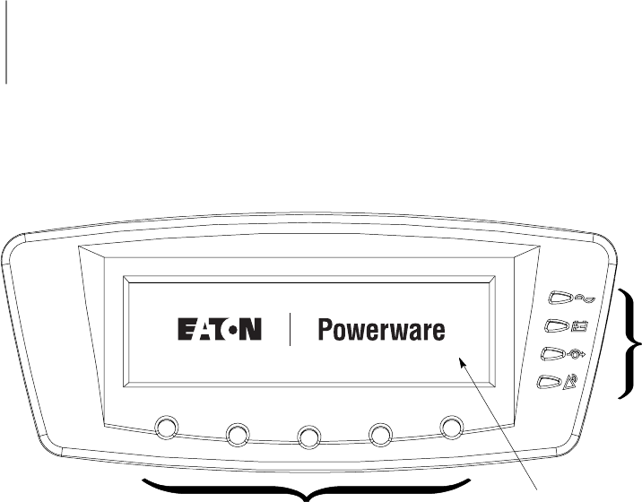
9-1
EATON Powerware®9390 UPS (100–160 kVA) Installation and Operation Manual S164201604 Rev B powerware.com
Chapter 9 Using the Control Panel
This chapter describes the UPS control panel, including controls and indicators, and how to
monitor UPS operation. The control panel (see Figure 9-1) is located on the front door of
the UPS.
3
1
2
PRESS ANY KEY TO CONTINUE
Figure 9-1. UPS Control Panel
The control panel consists of the following:
쑺A liquid crystal display (LCD) (1)
쑺A horizontal row of pushbutton switches (2)
쑺A vertical column of status indicators (3)
The following paragraphs describe using the UPS control panel to monitor the UPS. See
Chapter 10, “UPS Operating Instructions,” for use of the operational controls.
When the unit powers up, the screen displays the Eaton | Powerware logo as shown in
Figure 9-1. To advance to the Main Menu and Mimic screen, press any control panel
pushbutton once.
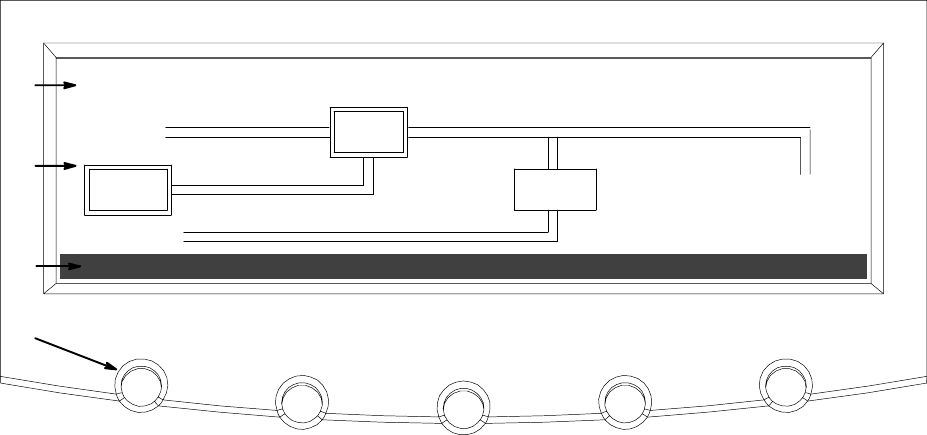
Using the Control Panel
9-2 EATON Powerware®9390 UPS (100–160 kVA) Installation and Operation Manual S164201604 Rev B powerware.com
9.1 Using the LCD and Pushbuttons
The LCD on the control panel provides an operator interface with the UPS system.
Figure 9-2 identifies the display areas discussed in the following sections.
METERSEVENTS SETUP
ALARM: INPUT AC UNDER VOLTAGE
OUTPUT
BATT
UPS
INPUT
STSW
A
B
C
D
CONTROLS LOAD OFF
BYPASS
Figure 9-2. Parts of the LCD
AThe UPS status area automatically scrolls between the Powerware model number, current date
and time, active alarms, active notices, and load percent and battery runtime for the UPS.
Shown is a typical alarm message. For more information about alarms and notices, see
Chapter 12, “Responding to System Events.”
BThe information area contains data about UPS status and operations.
CThe menu bar lists the titles of the available screens. To select a screen, press the pushbutton
underneath the desired screen.
DThe navigation pushbuttons function depending on the screen displayed. Use the pushbuttons
to select menu screens or scroll through availablescreens.TheLCDoptionsabovethe
pushbuttons indicate each pushbutton’s function.
You can use the LCD and the pushbuttons to:
쑺Look at a log of UPS events (alarms, notices, and commands) (see paragraph 9.2.2)
쑺Monitor UPS operation (see paragraph 9.2.3)
쑺Set UPS parameters (see paragraphs 9.2.8 and 9.2.9)
쑺Control UPS operation (see paragraph 9.3)
After approximately 30 minutes, the display screen darkens. To restore the screen, press
any pushbutton once.
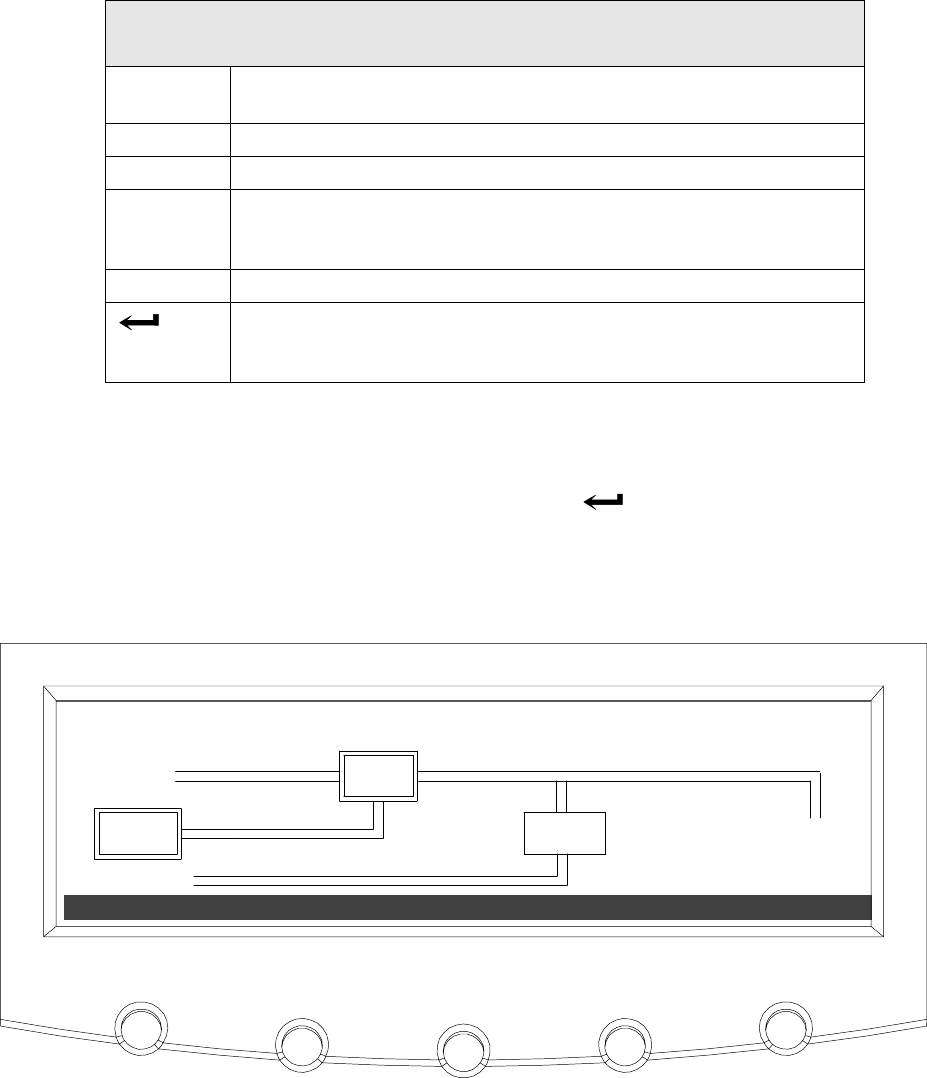
Using the Control Panel
9-3
EATON Powerware®9390 UPS (100–160 kVA) Installation and Operation Manual S164201604 Rev B powerware.com
9.2 Using the Main Menu
The UPS main menu bar allows you to display data in the information area to help you
monitor and control UPS operation. The following menus and options are available:
Menu
Option
Description
EVENTS Displays the list of Active System Events and a historical log of
system events.
METERS Displays performance meters for the system or critical load.
CONTROLS Displays the System Controls screen.
SETUP Allowsyoutosetthedisplaycontrast,setthedateandtimeforthe
time stamp, configure the UPS serial communication ports, and view
thefirmwareversionnumbers.
LOAD OFF De-energizes the critical load and powers down the UPS.
Returns to Main Menu and Mimic screen from the Events, Meters,
Controls, or Setup screens. Returns to the main System Setup Level
screen from a setup submenu.
9.2.1 Mimic Screen
Figure 9-3 shows the Main Menu and Mimic screen. To select the Mimic screen from the
Events, Meters, Controls, or Setup screens, press the pushbutton on the current menu
bar.
The Mimic screen shows the internal components of the UPS cabinet and a real-time
graphical representation of the operating status of the system.
TIME: 11 : 35 : 43 DATE: 02 / 25 / 2004
CONTROLS LOAD OFF
METERSEVENTS SETUP
OUTPUT
BATT
UPS
INPUT
STSW
BYPASS
Figure 9-3. Main Menu and Mimic Screen (Normal Mode)
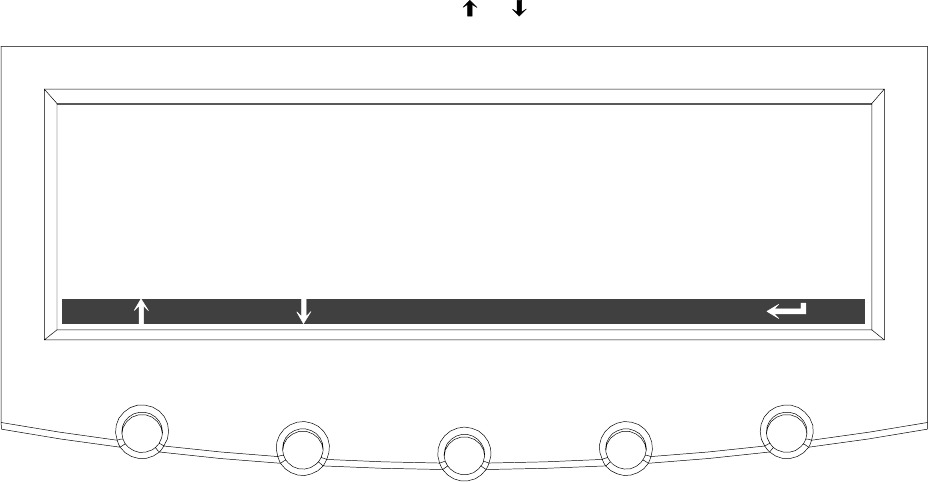
Using the Control Panel
9-4 EATON Powerware®9390 UPS (100–160 kVA) Installation and Operation Manual S164201604 Rev B powerware.com
9.2.2 Event Screens
Press the EVENTS pushbutton on the main menu bar or History Menu bar to display a
listing of all system events that are currently active. The most recent event is listed first. As
events clear, they are removed from the Active System Events listing. Figure 9-4 shows the
Active Events screen.
To scroll through the events, press the or pushbuttons on the menu bar.
ACTIVE EVENTS
HISTORY
ALARM: INPUT AC UNDERVOLTAGE
ALARM: BYPASS AC UNDER VOLTAGE
NOTICE: BATTERY VOLTAGE LOW
NOTICE: NO SYNC ON
NOTICE: BYPASS NOT AVAILABLE
NOTICE: CONFIGURATION ERROR
Figure 9-4. Active Events Screen
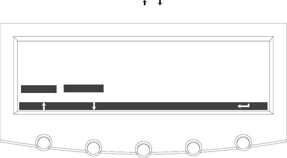
Using the Control Panel
9-5
EATON Powerware®9390 UPS (100–160 kVA) Installation and Operation Manual S164201604 Rev B powerware.com
Press the HISTORY pushbutton on the Active Events Menu bar to display the History Log.
The History Log lists up to the 500 system events in chronological order, with the most
recent event listed last (once 500 is reached, the earliest event is overwritten). The History
Log lists the events in the following groups:
쑺User and service status
쑺User instruction
쑺User alarm
쑺Check UPS
쑺Schedule service
쑺UPS shutdown
쑺Service alarm
The end of the log (the most recent events) appears when you display the screen, and you
must scroll upward to view older event listings. Figure 9-5 shows the History screen.
To scroll through the events, press the or pushbuttons on the menu bar. To return to
theActiveEventsscreen,presstheEVENTS pushbuttononthemenubar.
NOTICE:
ALARM:
NOTICE:
NOTICE:
5 of 29 02 / 26 / 2004 10 : 20 : 03 . 539
CONTROL POWER ON
BUILDING ALARM 1 OK
NORMAL COMMAND
TO BYPASS COMMAND
HISTORY
EVENTS
NOTICE: UPS OFF
Figure 9-5. History Screen
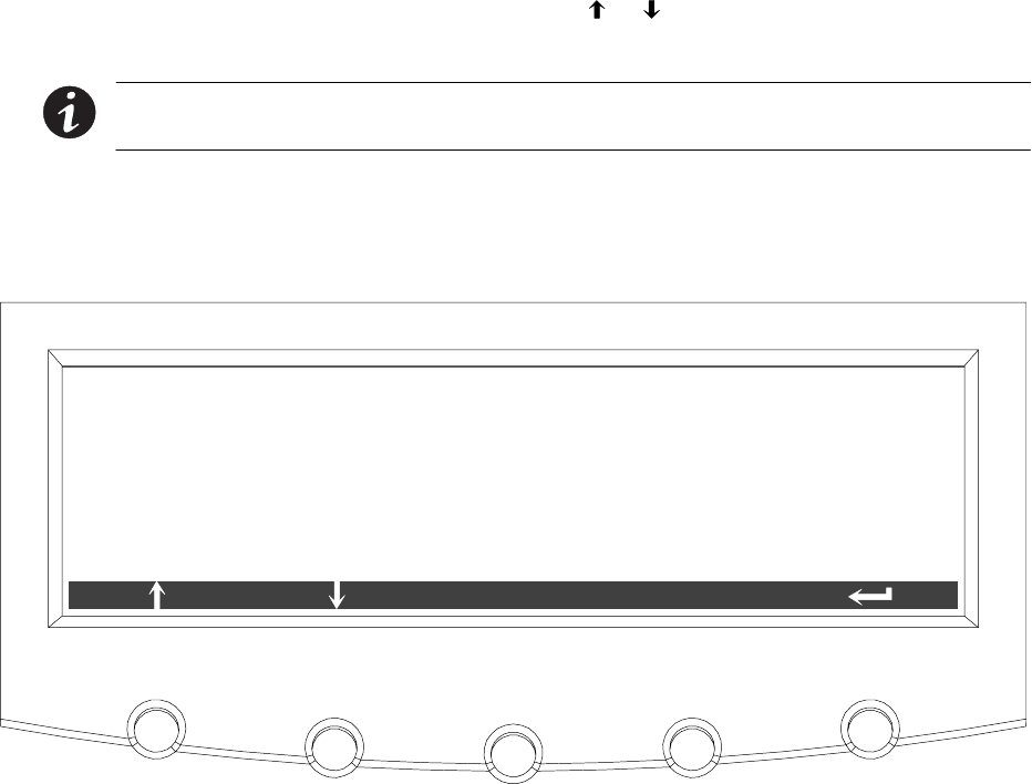
Using the Control Panel
9-6 EATON Powerware®9390 UPS (100–160 kVA) Installation and Operation Manual S164201604 Rev B powerware.com
9.2.3 Unit Meter Screens
The Unit Meter screens show the UPS meter readings for the unit (or units, if a parallel
system is installed). The default voltage displayed on these screens is phase-to-neutral.
However, an authorized Eaton Customer Service Engineer can change the screens to display
the voltage phase-to-phase (A-B, B-C, C-A).
Press the METERS pushbutton on the main menu bar to display the Unit Meter screens.
Figure 9-6 through Figure 9-10 show the Unit Meter screens.
To scroll through the meter screens, press the or pushbuttons on the menu bar. The
current UPS readings are displayed in the information area of the screen.
NOTE The UNIT designation after the meter type, and the SYSTEM and UNIT menu
bar pushbutton selections, are visible only when a parallel system is installed.
The Output screen shows output voltage (phase-to-neutral), output current (each phase),
and frequency being supplied by the UPS, as well as the kVA, kW, and power factor
measurements.
V1 V2 V3 KVA KW
PF
I1 I2 I3
***
*** *** ***
******
***
***
***
FREQ
***
OUTPUT --- UNIT
LEAD
UNITSYSTEM
Figure 9-6. Unit Output Meter Screen
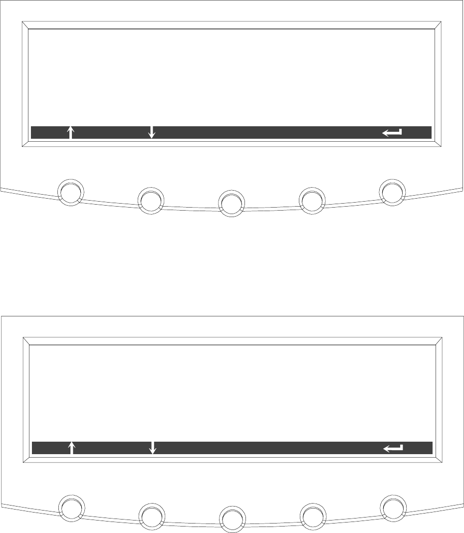
Using the Control Panel
9-7
EATON Powerware®9390 UPS (100–160 kVA) Installation and Operation Manual S164201604 Rev B powerware.com
The Input screen shows input voltage (phase-to-neutral), input current (each phase), and
frequency of the incoming utility source, as well as the kVA, kW, and power factor
measurements.
INPUT --- UNIT
V1 V2 V3 KVA KW
PF
I1 I2 I3
***
*** *** ***
******
***
***
***
FREQ
*** LEAD
UNITSYSTEM
Figure 9-7. Unit Input Meter Screen
The Bypass screen shows the bypass input voltage (phase-to-neutral), input current (each
phase), and frequency of the incoming utility source, as well as the kVA, kW, and power
factor measurements.
BY PA S S --- U N I T
V1 V2 V31 KVA KW
PF
I1 I2 I3
***
*** *** ***
******
***
***
***
FREQ
*** LEAD
UNITSYSTEM
Figure 9-8. Unit Bypass Meter Screen
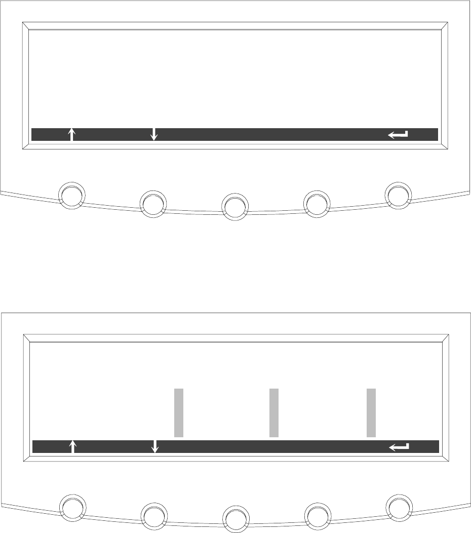
Using the Control Panel
9-8 EATON Powerware®9390 UPS (100–160 kVA) Installation and Operation Manual S164201604 Rev B powerware.com
The Battery screen displays the battery voltage (Vdc), the battery current (Idc), the minutes
of battery time remaining, and battery temperature. Battery temperature must be set up
by an authorized Eaton Customer Service Engineer. When battery life decreases to less than
20%, Check Battery is displayed.
VDC
IDC
TIME REMAINING
***
***
V
A
*** MINUTES
BATTERY --- UNIT
UNITSYSTEM
TEMPERATURE ** DEGREES C
Figure 9-9. Unit Battery Meter Screen
The Output Current Screen displays a real-time bar graph of the output current of the UPS.
The graph shows the current for each phase.
L2 L3125%
100%
75%
50%
25%
0%
OUTPUT CURRENT --- UNIT
L1
UNITSYSTEM
Figure 9-10. Unit Output Current (Load) Meter Screen
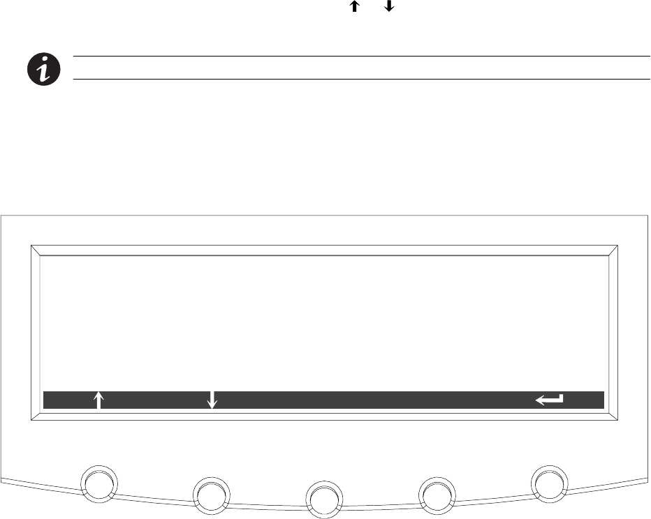
Using the Control Panel
9-9
EATON Powerware®9390 UPS (100–160 kVA) Installation and Operation Manual S164201604 Rev B powerware.com
9.2.4 Battery Discharge Log
Press the METERS pushbutton on the main menu bar to display the Unit Meter screens.
Scroll through the meter screens using the or pushbuttons on the menu bar until the
Battery Discharge Log Summary screen is displayed.
NOTE The Battery Discharge Log is available only when the mini-CSB is installed.
Thebatterydischargelogcollectsinformation when the unit is on battery. The Battery
Discharge Log Summary screen displays the total number of times since the last log reset
that the unit has transferred to battery. It also displays the date of the last log reset, the
average time spent on battery per event, and the total time on battery since the last reset.
Figure 9-11 shows the Battery Discharge Log Summary screen.
BATTERY DISCHARGE LOG SUMMARY
LOG
NUMBER OF TIMES ON BATTERY
AVERAGE TIME ON BATTERY
TOTAL TIME ON BATTERY
LAST LOG RESET
1
07/28/2005
** M ** S
** H ** M
Figure 9-11. Battery Discharge Log Summary Screen
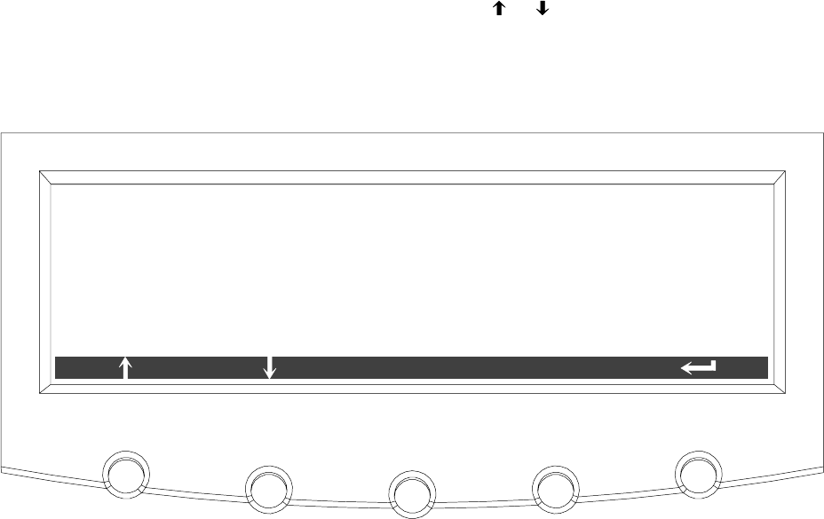
Using the Control Panel
9-10 EATON Powerware®9390 UPS (100–160 kVA) Installation and Operation Manual S164201604 Rev B powerware.com
Press the LOG pushbutton on the Battery Discharge Log Summary Menu bar to display the
Battery Discharge Log screen.
TheBatteryDischargeLogscreendisplaystheindividuallogentriesincludingthedateand
time of the event, how long it was on battery, the unit load when the event occurred, and
the end voltage of the battery for that discharge period. If no events have occurred, the
screen will display LOG EMPTY. Figure 9-12 shows the Battery Discharge Log screen.
To scroll through the individual events, press the or pushbuttons on the menu bar. To
return to the Battery Discharge Log Summary screen, press the SUMMARY pushbutton on
the menu bar.
To clear the Battery Discharge Log, press the RESET pushbuttononthemenubar.
BATTERY DISCHARGE LOG
SUMMARY
DATE : 07/28/2005
LOAD WHEN ON BATTERY
END VOLTAGE :
TIME ON BATTERY
TIME : 15 : 26 : 10
***.** KW
***.** V
RESET
BATTERY DISCHARGE EVENT 1/ 1
** M ** S
Figure 9-12. Battery Discharge Log Screen
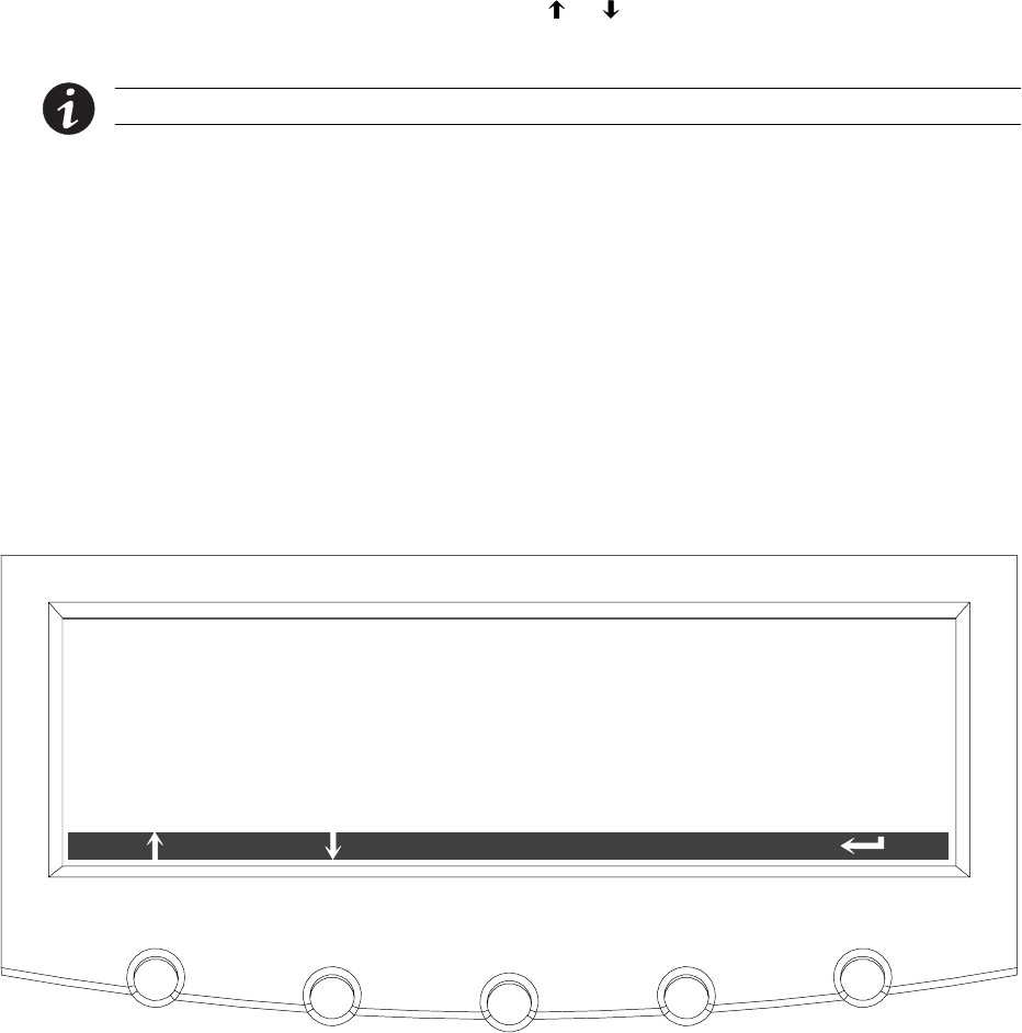
Using the Control Panel
9-11
EATON Powerware®9390 UPS (100–160 kVA) Installation and Operation Manual S164201604 Rev B powerware.com
9.2.5 KW Demand Log
Press the METERS pushbutton on the main menu bar to display the Unit Meter screens.
Scroll through the meter screens using the or pushbuttons on the menu bar until the
KW Demand Log Summary screen is displayed.
NOTE The KW Demand Log is available only when the mini-CSB is installed.
The KW demand log collects information on events where the unit load exceeds a
user-defined KW limit within a user-defined time interval. The user can choose a time
period up to 9999 minutes and a load limit up to 9999 KW. If the limit is exceeded within a
given time period a log event is created. The KW Demand Log Summary screen displays the
number of total times the limit has been exceeded since the last log reset, the date of the
last log reset, the maximum KW reading, and the total time over the limit. It also displays
the average KW over the limit and an estimated number of KWH used over the limit. Both
of these values are calculated using the difference between the actual measurement
reading and the user-defined limit level. For example, during a 60-minute interval if the
limit is set at 10 KW and the measurement is a constant 15 KW for the entire period, the
averageKWoverwouldbe5KWandthetotalKWHusedoverthelimitwouldbe5KWH.
Figure 9-13 shows the KW Demand Log Summary screen.
KW DEMAND LOG SUMMARY
LOG
LAST LOG RESET
AVERAGE KW OVER LIMIT
TOTAL TIME OVER LIMIT
MAXIMUM READING (KW)
12
07/30/2005
** MINUTES
NUMBER OF TIMES OVER LIMIT
TOTAL KWH USED OVER LIMIT
*** . ** KW
*** . ** KW
*** . ** KWH
SETUP
Figure 9-13. KW Demand Log Summary Screen

Using the Control Panel
9-12 EATON Powerware®9390 UPS (100–160 kVA) Installation and Operation Manual S164201604 Rev B powerware.com
Press the LOG pushbutton on the KW Demand Log Summary Menu bar to display the KW
Demand Log screen.
The KW Demand Log screen displays the individual log entries, including the interval date
and time frame, the maximum reading during the interval, the total time over limit during
the interval, an estimated number of total KWH used during the interval, and the number
of times over limit during the interval. If no events have occurred, the screen displays LOG
EMPTY. Figure 9-14 shows the KW Demand Log screen.
To scroll through the individual events, press the or pushbuttons on the menu bar. To
return to the KW Demand Log Summary screen, press the SUMMARY pushbuttononthe
menu bar.
To clear the KW Demand Log, press the RESET pushbuttononthemenubar.
KW DEMAND LOG
SUMMARY
INTERVAL : 07/30/2005
TIME OVER LIMIT
KWH USED OVER LIMIT
MAXIMUM READING (KW)
15 : 26 : 10 – 15 : 30 : 10
*** . ** KW
2MINUTES
*** . **
RESET
KW DEMAND EVENT
NUM TIMES OVER THIS INTERVAL
6/ 12
3
Figure 9-14. KW Demand Log Screen
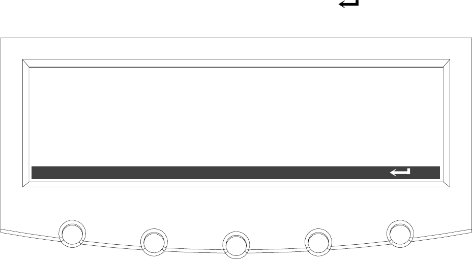
Using the Control Panel
9-13
EATON Powerware®9390 UPS (100–160 kVA) Installation and Operation Manual S164201604 Rev B powerware.com
Press the SETUP pushbutton on the KW Demand Log Summary Menu bar to display the
Current KW Demand Log Setup screen 1.
The Current KW Demand Log Setup screen 1 displays the current user-defined log settings.
If no log settings are configured, the screen will display KW LOG DISABLED. Figure 9-15
shows the Current KW Demand Log Setup screen 1.
To return to the KW Demand Log Summary screen, press the pushbuttononthe
menu bar.
CURRENT KW DEMAND LOG SETUP
CHANGE
TIME INTERVAL MONITORED
MAXIMUM LEVEL (KW)
3MINUTES
*** KW
Figure 9-15. Current KW Demand Log Setup Screen 1
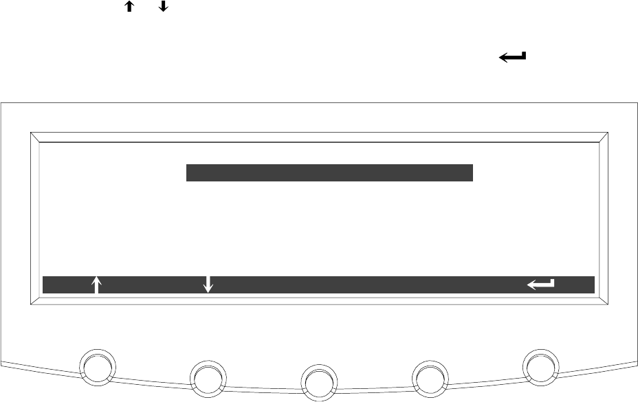
Using the Control Panel
9-14 EATON Powerware®9390 UPS (100–160 kVA) Installation and Operation Manual S164201604 Rev B powerware.com
Press the CHANGE pushbutton on the Current KW Demand Log Setup Menu bar to display
the Current KW Demand Log Setup screen 2.
The Current KW Demand Log Setup screen can be used to set up or change the time
interval and maximum level log settings. Figure 9-16 shows the Current KW Demand Log
Setup screen 2.
Use the or pushbuttons to highlight the setup function screen desired, then press the
SELECT pushbutton to display the function screen.
To return to the Current KW Demand Log Setup screen 1, press the pushbutton on
the menu bar.
TIME INTERVAL MONITORED
CURRENT KW DEMAND LOG SETUP
SELECT
MAXIMUM LEVEL (KW)
Figure 9-16. Current KW Demand Log Setup Screen 2

Using the Control Panel
9-15
EATON Powerware®9390 UPS (100–160 kVA) Installation and Operation Manual S164201604 Rev B powerware.com
Select TIME INTERVAL MONITORED from the Current KW Demand Log Setup screen 2
menu to display the Time Interval Monitored Setup screen. The Time Interval Monitored
Setup screen allows the time duration of the event being monitored to be changed.
Figure 9-17 shows the Time Interval Monitored Setup screen.
Use the or pushbuttons to select the character position. Use the or pushbuttons
to change the character value. Once the new value is entered, press the DONE
pushbutton. The Time Interval Monitored Setup Save screen is displayed.
0000
DONE
TIME INTERVAL MONITORED SETUP
Figure 9-17. Time Interval Monitored Setup Screen
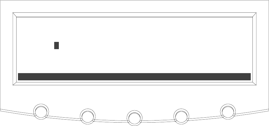
Using the Control Panel
9-16 EATON Powerware®9390 UPS (100–160 kVA) Installation and Operation Manual S164201604 Rev B powerware.com
TheTimeIntervalMonitoredSetupSavescreenletsyousavethenewtimeinterval,retry
another time interval, or abort the change. Figure 9-18 shows the Time Interval Monitored
Setup Save screen.
Press SAVE,RETRY,orABORT. If SAVE or ABORT is pressed, the action is completed, and
the Current KW Demand Log Setup screen 2 displays. If RETRY is pressed, the Time Interval
Monitored Setup screen is redisplayed.
ABORT
SAVE RETRY
0000
TIME INTERVAL MONITORED SETUP
Figure 9-18. Time Interval Monitored Setup Save Screen

Using the Control Panel
9-17
EATON Powerware®9390 UPS (100–160 kVA) Installation and Operation Manual S164201604 Rev B powerware.com
Select MAXIMUM LEVEL (KW) from the Current KW Demand Log Setup screen 2 menu to
display the Maximum Level (KW) Setup screen. The Maximum Level (KW) Setup screen
allows the KW limit of the event being monitored to be changed. Figure 9-19 shows the
Maximum Level (KW) Setup screen.
Use the or pushbuttons to select the character position. Use the or pushbuttons
to change the character value. Once the new value is entered, press the DONE
pushbutton. The Maximum Level (KW) Setup Save screen is displayed.
0000
DONE
MAXIMUM LEVEL (KW) SETUP
Figure 9-19. Maximum Level (KW) Setup Screen

Using the Control Panel
9-18 EATON Powerware®9390 UPS (100–160 kVA) Installation and Operation Manual S164201604 Rev B powerware.com
The Maximum Level (KW) Setup Save screen lets you save the new KW limit, retry another
KW limit, or abort the change. Figure 9-20 shows the Maximum Level (KW) Setup Save
screen.
Press SAVE,RETRY,orABORT. If SAVE or ABORT is pressed, the action is completed, and
the Current KW Demand Log Setup screen 2 displays. If RETRY is pressed, the Maximum
Level (KW) Setup screen is redisplayed.
ABORT
SAVE RETRY
0000
MAXIMUM LEVEL (KW) SETUP
Figure 9-20. Maximum Level (KW) Setup Save Screen

Using the Control Panel
9-19
EATON Powerware®9390 UPS (100–160 kVA) Installation and Operation Manual S164201604 Rev B powerware.com
9.2.6 Maximum Current Log
Press the METERS pushbutton on the main menu bar to display the Unit Meter screens.
Scroll through the meter screens using the or pushbuttons on the menu bar until the
Maximum Current Log Summary screen is displayed.
NOTE The Maximum Current Log is available only when the mini-CSB is installed.
The maximum current log collects information on events where the unit load exceeds a
user-defined current limit within a user-defined time interval. The user can choose a time
period up to 9999 minutes and a load limit up to 100%. The user can also select whether
thelimitdefinedisathree-phaseaverageoftheindividualphasecurrentsorisalimit
defined for each phase individually. In the first case an event is logged if the average across
the phases exceeds the defined limit within a given time period and in the second case an
event is logged if any individual phase exceeds the defined limit within a given time period.
The Maximum Current Log Summary screen displays the number of times the limit has
been exceeded, the date of the last log reset, the maximum percent of full load, and the
total time over the limit. It also displays the average percent load over the limit. This
measurement differs, depending on whether a three-phase average or an individual phase
measurement is selected. Figure 9-21 shows the Maximum Current Log Summary screen.
MAXIMUM CURRENT LOG SUMMARY
LOG
LAST LOG RESET
AVERAGE % OF FULL LOAD
TOTAL TIME OVER LIMIT
MAXIMUM % OF FULL LOAD
5
08/04/2005
** MINUTES
NUMBER OF TIMES OVER LIMIT
*** . ** %
*** . ** %
SETUP
Figure 9-21. Maximum Current Log Summary Screen
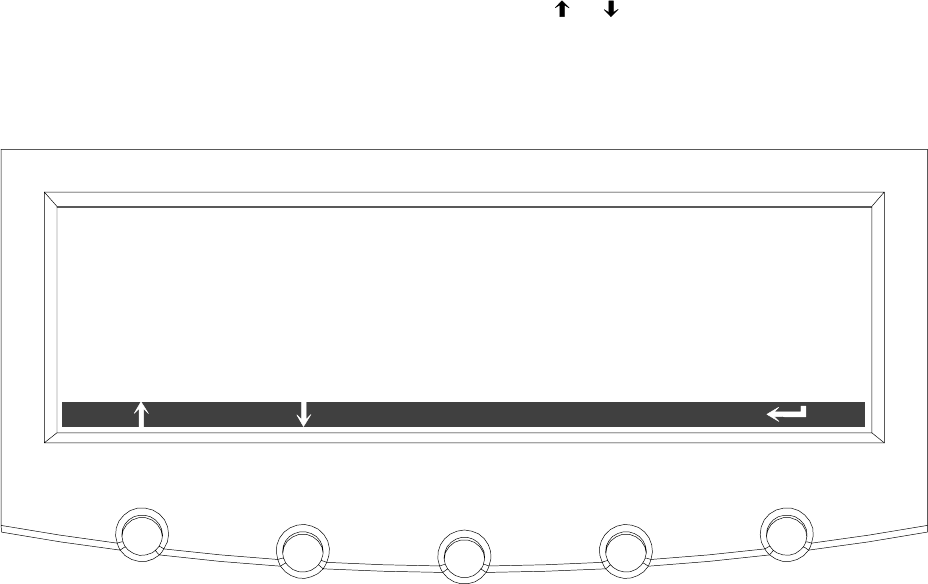
Using the Control Panel
9-20 EATON Powerware®9390 UPS (100–160 kVA) Installation and Operation Manual S164201604 Rev B powerware.com
Press the LOG pushbutton on the Maximum Current Log Summary Menu bar to display the
Maximum Current Log screen.
The Maximum Current Log screen displays the individual log entries, including the interval
date and time frame, the maximum percent of full load during the interval, the total time
over limit during the interval, and the number of times over during the interval. If the
individual phase option is selected, the phases that exceeded the limit will also be
displayed. If no events have occurred, the screen will display LOG EMPTY. Figure 9-22 and
Figure 9-23 show the Maximum Current Log screens.
To scroll through the individual events, press the or pushbuttons on the menu bar. To
return to the Maximum Current Log Summary screen, press the SUMMARY pushbutton on
the menu bar.
To clear the Maximum Current Log, press the RESET pushbuttononthemenubar.
MAXIMUM CURRENT LOG
SUMMARY
INTERVAL : 07/30/2005
TIME OVER LIMIT
15 : 26 : 10 – 15 : 30 : 10
*** . ** %
2MINUTES
3
RESET
MAXIMUM CURRENT EVENT
NUM TIMES OVER THIS INTERVAL
2/ 5
MAXIMUM % OF FULL LOAD
Figure 9-22. Maximum Current Log Screen (Three-Phase Measurement)
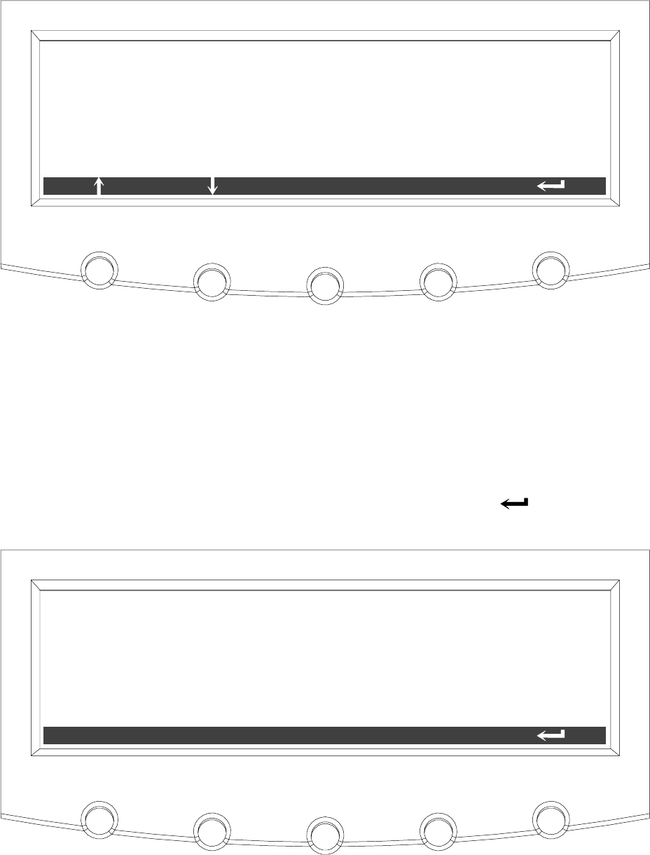
Using the Control Panel
9-21
EATON Powerware®9390 UPS (100–160 kVA) Installation and Operation Manual S164201604 Rev B powerware.com
MAXIMUM CURRENT LOG
SUMMARY
INTERVAL : 07/30/2005
TIME OVER LIMIT
15 : 26 : 10 – 15 : 30 : 10
*** . ** %
2MINUTES
3
RESET
MAXIMUM CURRENT EVENT
NUM TIMES OVER THIS INTERVAL
2/ 5
MAXIMUM % OF FULL LOAD
PHASES OVER THIS INTERVAL 1 2
Figure 9-23. Maximum Current Log Screen (Individual Phase Measurement)
Press the SETUP pushbutton on the Maximum Current Log Summary Menu bar to display
the Maximum Current Log Setup screen 1.
The Maximum Current Log Setup screen 1 displays the current user defined log settings. If
no log settings are configured, the screen will display MAXIMUM CURRENT LOG DISABLED.
Figure 9-24 shows the Maximum Current Log Setup screen 1.
To return to the Maximum Current Log Summary screen, press the pushbutton on the
menu bar.
MAXIMUM CURRENT LOG SETUP
CHANGE
TIME INTERVAL MONITORED 3MINUTES
*** %
LEVEL BASED ON 3 PHASE AVERAGE
MAXIMUM % OF FULL LOAD
Figure 9-24. Maximum Current Log Setup Screen 1
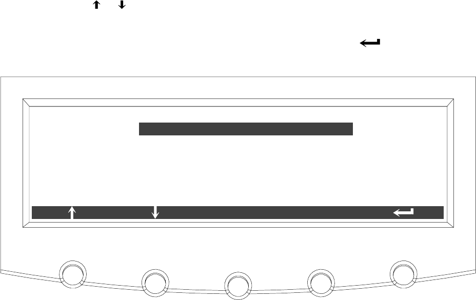
Using the Control Panel
9-22 EATON Powerware®9390 UPS (100–160 kVA) Installation and Operation Manual S164201604 Rev B powerware.com
Press the CHANGE pushbutton on the Maximum Current Log Setup Menu bar to display
the Maximum Current Log Setup screen 2.
The Maximum Current Log Setup screen can be used to set up or change the time interval,
the maximum percent of load, and the calculation method (three-phase average or
individual phases) log settings. Figure 9-25 shows the Maximum Current Log Setup
screen 2.
Use the or pushbuttons to highlight the setup function screen desired, then press the
SELECT pushbutton to display the function screen.
To return to the Maximum Current Log Setup screen 1, press the pushbuttononthe
menu bar.
TIME INTERVAL MONITORED
MAXIMUM CURRENT LOG SETUP
SELECT
MAXIMUM % OF FULL LOAD
CALCULATION METHOD
Figure 9-25. Maximum Current Log Setup Screen 2

Using the Control Panel
9-23
EATON Powerware®9390 UPS (100–160 kVA) Installation and Operation Manual S164201604 Rev B powerware.com
Select TIME INTERVAL MONITORED from the Maximum Current Log Setup screen 2
menu to display the Time Interval Monitored Setup screen. The Time Interval Monitored
Setup screen allows the time duration of the event being monitored to be changed.
Figure 9-26 shows the Time Interval Monitored Setup screen.
Use the or pushbuttons to select the character position. Use the or pushbuttons
to change the character value. Once the new value is entered, press the DONE
pushbutton. The Time Interval Monitored Setup Save screen is displayed.
0000
DONE
TIME INTERVAL MONITORED SETUP
Figure 9-26. Time Interval Monitored Setup Screen

Using the Control Panel
9-24 EATON Powerware®9390 UPS (100–160 kVA) Installation and Operation Manual S164201604 Rev B powerware.com
TheTimeIntervalMonitoredSetupSavescreenletsyousavethenewtimeinterval,retry
another time interval, or abort the change. Figure 9-18 shows the Time Interval Monitored
Setup Save screen.
Press SAVE,RETRY,orABORT. If SAVE or ABORT is pressed, the action is completed, and
the Maximum Current Log Setup screen 2 displays. If RETRY is pressed, the Time Interval
Monitored Setup screen is redisplayed.
ABORT
SAVE RETRY
0000
TIME INTERVAL MONITORED SETUP
Figure 9-27. Time Interval Monitored Setup Save Screen
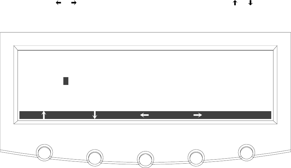
Using the Control Panel
9-25
EATON Powerware®9390 UPS (100–160 kVA) Installation and Operation Manual S164201604 Rev B powerware.com
Select MAXIMUM % of FULL LOAD from the Maximum Current Log Setup screen
(screen 2) menu to display the Maximum % of Full Load Setup screen. The Maximum % of
Full Load Setup screen allows the full load limit of the event being monitored to be
changed. Figure 9-28 shows the Maximum % of Full Load Setup screen.
Use the or pushbuttons to select the character position. Use the or pushbuttons
to change the character value. Once the new value is entered, press the DONE
pushbutton. The Maximum % of Full Load Setup Save screen is displayed.
000
DONE
MAXIMUM % OF FULL LOAD SETUP
Figure 9-28. Maximum % of Full Load Setup Screen

Using the Control Panel
9-26 EATON Powerware®9390 UPS (100–160 kVA) Installation and Operation Manual S164201604 Rev B powerware.com
The Maximum % of Full Load Setup Save screen lets you save the new load limit, retry
another load limit, or abort the change. Figure 9-29 shows the Maximum % of Full Load
Setup Save screen.
Press SAVE,RETRY,orABORT. If SAVE or ABORT is pressed, the action is completed, and
the Maximum Current Log Setup screen 2 displays. If RETRY is pressed, the Maximum % of
Full Load Setup screen is redisplayed.
ABORT
SAVE RETRY
000
MAXIMUM % OF FULL LOAD SETUP
Figure 9-29. Maximum % of Full Load Setup Save Screen
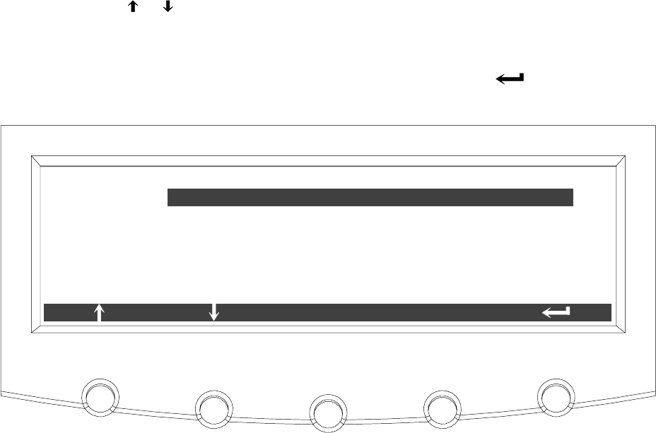
Using the Control Panel
9-27
EATON Powerware®9390 UPS (100–160 kVA) Installation and Operation Manual S164201604 Rev B powerware.com
Select CALCULATION METHOD from the Maximum Current Log Setup screen 2 menu to
display the Calculation Method Setup screen. The Calculation Method Setup screen allows
the full load limit of the event being monitored to be changed. Figure 9-30 shows the
Calculation Method Setup screen.
Use the or pushbuttons to highlight the calculation method desired, then press the
SELECT pushbutton. The action is completed, and the Maximum Current Log Setup
screen 2 displays.
To return to the Maximum Current Log Setup screen 1, press the pushbuttononthe
menu bar.
LEVEL BASED ON 3 PHASE AVERAGE
MAXIMUM CURRENT LOG SETUP
SELECT
LEVEL BASED ON INDIVIDUAL PHASES
Figure 9-30. Calculation Method Setup Screen
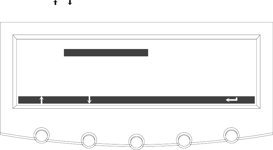
Using the Control Panel
9-28 EATON Powerware®9390 UPS (100–160 kVA) Installation and Operation Manual S164201604 Rev B powerware.com
9.2.7 System Meters Screens
The System Meters screens show the total system and individual UPS unit meter readings
from any unit, when a parallel system is installed. The default voltage displayed on these
screens is phase-to-neutral. However, an authorized Eaton Customer Service Engineer can
changethescreenstodisplaythevoltage phase-to-phase (A-B, B-C, C-A).
Press the METERS pushbutton on the main menu bar to display the Unit Meter screens.
Press the SYSTEM pushbutton on the menu bar to display the System Meters screen.
Use the or pushbuttons to highlight the Total System meter or Unit meters desired,
then press the SELECT pushbutton to display the screen.
ENTER PASS-
WORD
TOTAL SYSTEM
UNIT 3
UNIT 4
UNIT 2
UNIT 1
SYSTEM METERS
SELECT
Figure 9-31. System Meters Screen
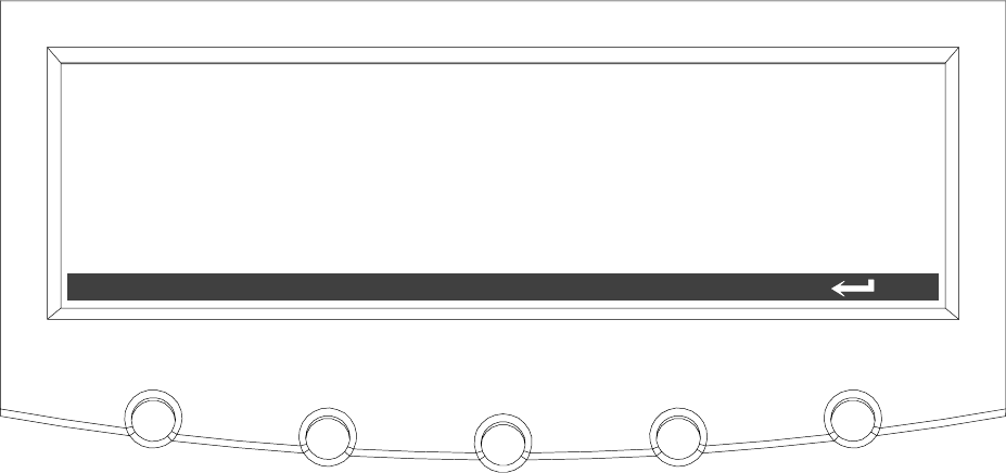
Using the Control Panel
9-29
EATON Powerware®9390 UPS (100–160 kVA) Installation and Operation Manual S164201604 Rev B powerware.com
The Output Total System screen shows output voltage (phase-to-neutral), output current
(each phase), and frequency being supplied by the UPS, as well as the kVA, kW, and power
factor measurements for the total system. The displayed voltages and frequency are the
highest measured value of all units. The displayed currents, kVA, and kW are totals of all
units, and the PF is calculated from the total values for the kVA and kW.
V1 V2 V3 KVA KW
PF
I1 I2 I3
***
*** *** ***
******
***
***
***
FREQ
***
OUTPUT TOTAL SYSTEM
LEAD
UNITSYSTEM
Figure 9-32. Total System Output Meter Screen
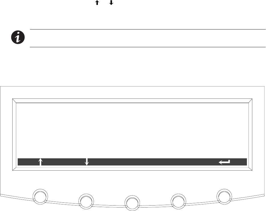
Using the Control Panel
9-30 EATON Powerware®9390 UPS (100–160 kVA) Installation and Operation Manual S164201604 Rev B powerware.com
Figure 9-33 through Figure 9-37 show the System Meters screens. To scroll through the
meter screens, press the or pushbuttons on the menu bar. The current UPS readings
for the selected unit are displayed in the information area of the screen. To return to the
present Unit Meter screens, press the UNIT pushbuttononthemenubar.
NOTE In the following figures, “X” equals the unit number selected from the System
Meters screen.
The Output screen shows output voltage (phase-to-neutral), output current (each phase),
and frequency being supplied by the UPS, as well as the kVA, kW, and power factor
measurements for the selected unit.
V1 V2 V3 KVA KW
PF
I1 I2 I3
***
*** *** ***
******
***
***
***
FREQ
***
OUTPUT UNIT X
LEAD
UNITSYSTEM
Figure 9-33. Output Unit X Meter Screen

Using the Control Panel
9-31
EATON Powerware®9390 UPS (100–160 kVA) Installation and Operation Manual S164201604 Rev B powerware.com
The Input screen shows input voltage (phase-to-neutral), output current (each phase), and
frequency of the incoming utility source, as well as the kVA, kW, and power factor
measurements for the selected unit.
INPUTUNITX
V1 V2 V3 KVA KW
PF
I1 I2 I3
***
*** *** ***
******
***
***
***
FREQ
*** LEAD
UNITSYSTEM
Figure 9-34. Input Unit X Meter Screen
The Bypass screen shows the bypass input voltage (phase-to-neutral), output current (each
phase), and frequency of the incoming utility source, as well as the kVA, kW, and power
factor measurements for the selected unit.
BYPASS UNIT X
V1 V2 V3 KVA KW
PF
I1 I2 I3
***
*** *** ***
******
***
***
***
FREQ
*** LEAD
UNITSYSTEM
Figure 9-35. Bypass Unit X Meter Screen

Using the Control Panel
9-32 EATON Powerware®9390 UPS (100–160 kVA) Installation and Operation Manual S164201604 Rev B powerware.com
The Battery screen displays the battery voltage (Vdc), the battery current (Idc), the minutes
of battery time remaining, and battery temperature. Battery temperature must be set up
by an authorized Eaton Customer Service Engineer When battery life decreases to less
than 20%, Check Battery is displayed.
VDC
IDC
TIME REMAINING
***
***
V
A
*** MINUTES
BATTERY UNIT X
UNITSYSTEM
TEMPERATURE ** DEGREES C
Figure 9-36. Battery Unit X Meter Screen
The Output Current screen displays a real-time bar graph of the output current of the UPS
for the selected unit. The graph shows the current for each phase.
L2 L3125%
100%
75%
50%
25%
0%
OUTPUT CURRENT UNIT X
L1
UNITSYSTEM
Figure 9-37. Output Current (Load) Unit X Meter Screen
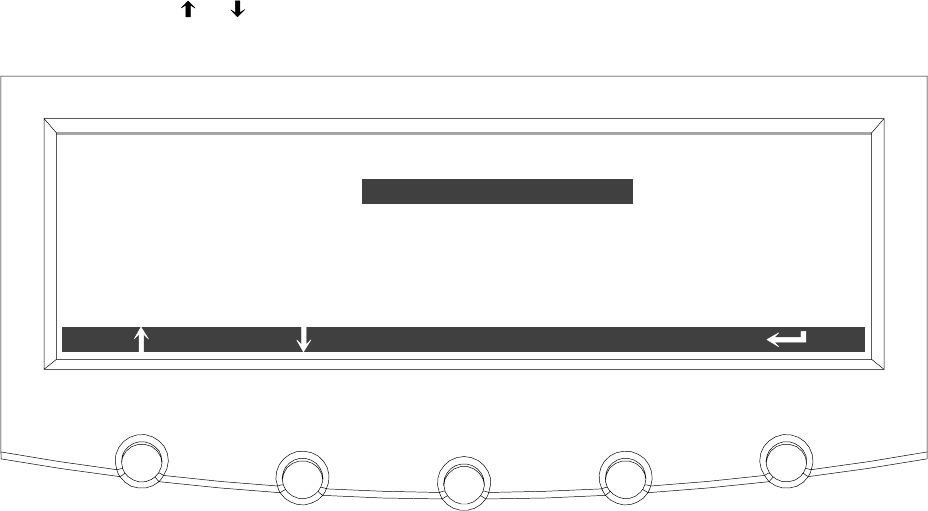
Using the Control Panel
9-33
EATON Powerware®9390 UPS (100–160 kVA) Installation and Operation Manual S164201604 Rev B powerware.com
9.2.8 System Setup Level 0 Screens
Press the SETUP pushbutton on the main menu bar to display the System Setup Level 0
Screen. This screen can be used to:
쑺Enter a password to access Level 1 functions (see paragraph 9.2.9)
No password is necessary to access Level 0 functions.
쑺Set the screen contrast
쑺Showthefirmwareversionsinstalled
쑺Identify the unit type
Figure 9-38 shows the System Setup Level 0 menu screen.
Use the or pushbuttons to highlight the setup function screen desired, then press the
SELECT pushbutton to display the function screen.
ENTER PASSWORD
CONTRAST ADJUST
VERSIONS
UNIT TYPE
SYSTEM SETUP LEVEL 0
SELECT
Figure 9-38. System Setup Level 0 Screen
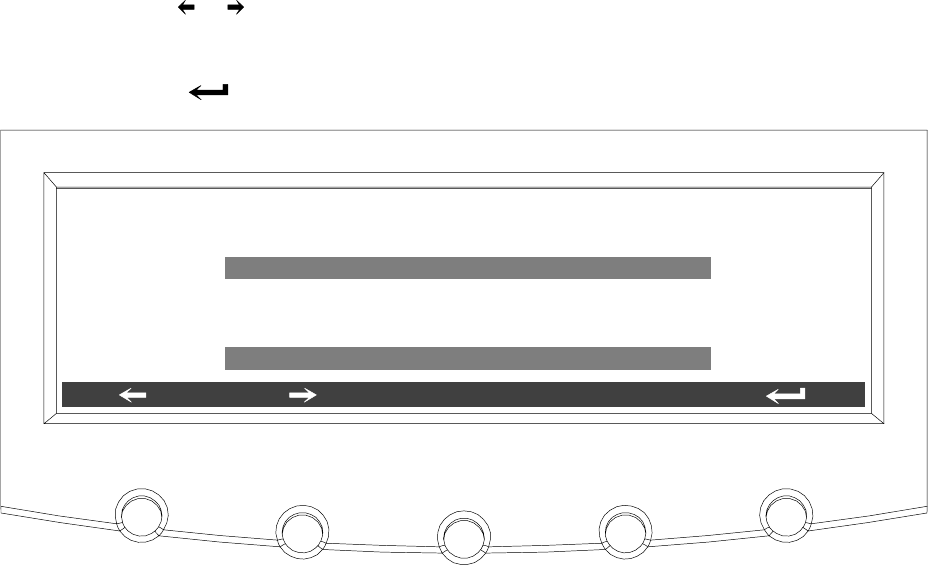
Using the Control Panel
9-34 EATON Powerware®9390 UPS (100–160 kVA) Installation and Operation Manual S164201604 Rev B powerware.com
Select CONTRAST from the System Setup Level 0 menu to display the Contrast Adjust
screen. Figure 9-39 shows the Contrast Adjust screen.
Use the or pushbuttons to adjust the contrast for the LCD. When the contrast
adjustment is complete, press the SAVE pushbutton. Once the setting is saved, the System
Setup screen displays. To return to the System Setup screen without saving the setting,
press the pushbutton.
CONTRAST ADJUST
70%
SAVE
Figure 9-39. Contrast Adjust Screen
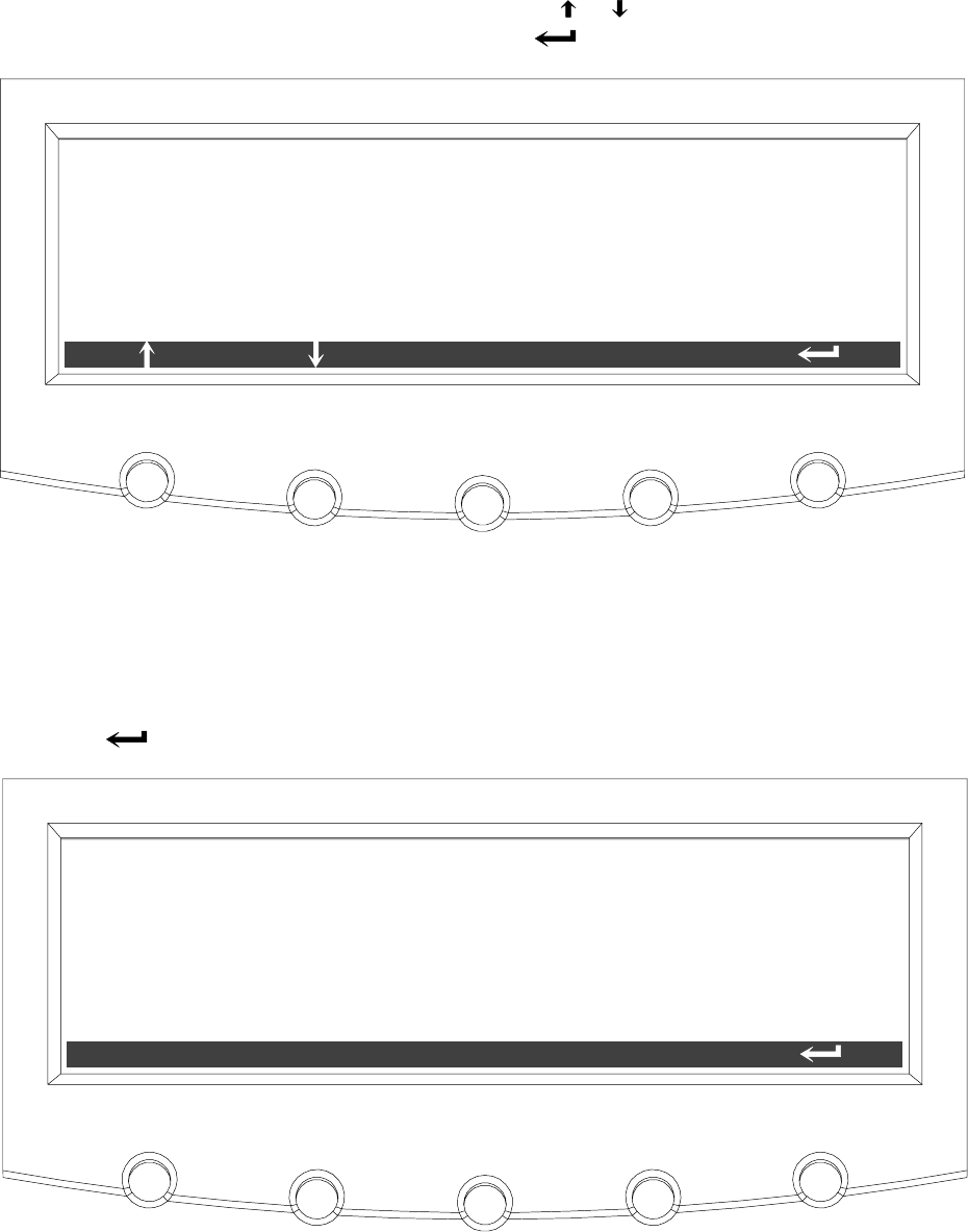
Using the Control Panel
9-35
EATON Powerware®9390 UPS (100–160 kVA) Installation and Operation Manual S164201604 Rev B powerware.com
Select VERSIONS from the System Setup Level 0 menu to display the Versions screen. The
Versions screen provides the firmware version numbers installed on the UPS. Figure 9-40
shows the Versions screen.
To scroll through the firmware types, press the or pushbuttons on the menu bar. To
return to the System Setup screen, press the pushbutton.
DSP
DISPLAY
MINI CSB
57.00
0.54
GATE DRIVE 3.00
0.00
VERSIONS
PLD 1
BOOTLOADER 0.00
Figure 9-40. Versions Screen
Select UNIT TYPE from the System Setup Level 0 menu to display the Unit Type screen.
The Unit Type screen provides the model, CTO, and serial numbers of the UPS unit.
Figure 9-41 shows the Unit Type screen. To return to the System Setup screen, press the
pushbutton.
MODEL:
CTO: POWERWARE 9390
SERIAL: 0000000000000000
0000000000000000
UNIT TYPE
Figure 9-41. Unit Type Screen

Using the Control Panel
9-36 EATON Powerware®9390 UPS (100–160 kVA) Installation and Operation Manual S164201604 Rev B powerware.com
9.2.9 System Setup Level 1 Screens
A password is required to access the Level 1 functions. To enter the password, select
ENTER PASSWORD from the System Setup Level 0 menu to display the Enter Password
screen. Figure 9-42 shows the Enter Password screen.
Use the or pushbuttons to select the password character position. Use the or
pushbuttons to change the password character. Once the password is entered, press the
DONE pushbutton. The System Setup Level 1 menu screen is displayed. The default
password is L1.
L1
ENTER PASSWORD
DONE
Figure 9-42. Enter Password Screen
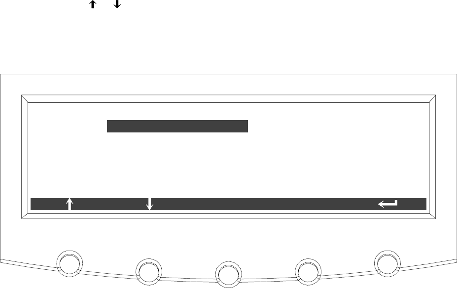
Using the Control Panel
9-37
EATON Powerware®9390 UPS (100–160 kVA) Installation and Operation Manual S164201604 Rev B powerware.com
The System Setup Level 1 screen can be used to set the UPS date and time, set the serial
ports, change the Level 1 password, and log out of Level 1. In addition, the Level 0
functions are available. Figure 9-43 shows the System Setup Level 1 screen.
Use the or pushbuttons to highlight the setup function screen desired, then press the
SELECT pushbutton to display the function screen.
The Level 1 screen times out after 60 minutes or can be logged out at any time by
selecting the LOG OUT function from the menu screen.
ENTER PASS-
WORD
LOG OUT
CONTRAST ADJUST
VERSIONS
CHANGE PASSWORD
ENTER PASSWORD
SYSTEM SETUP LEVEL 1
SELECT
UNIT TYPE
Figure 9-43. System Setup Level 1 Screen
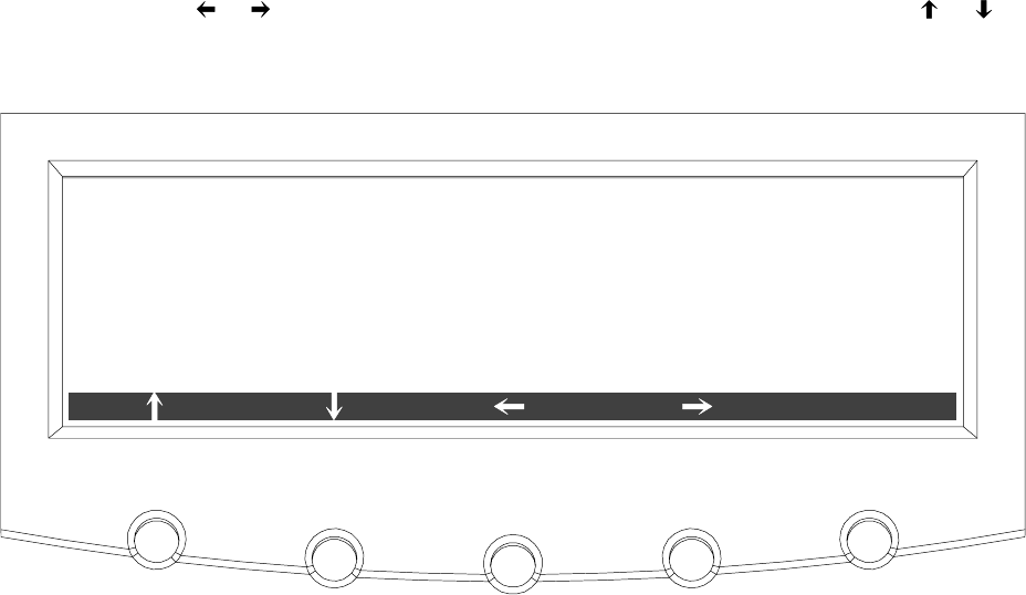
Using the Control Panel
9-38 EATON Powerware®9390 UPS (100–160 kVA) Installation and Operation Manual S164201604 Rev B powerware.com
Select CHANGE PASSWORD from the System Setup Level 1 menu to display the Change
Password screen. The Change Password screen allows the System Setup Level 1 password to
be changed. Figure 9-44 shows the Change Password screen.
Use the or pushbuttons to select the password character position. Use the or
pushbuttons to change the password character. Once the new password is entered, press
the DONE pushbutton. The Change Password Save screen is displayed.
NEW:
OLD: L1
L1
CHANGE PASSWORD
DONE
Figure 9-44. Change Password Screen

Using the Control Panel
9-39
EATON Powerware®9390 UPS (100–160 kVA) Installation and Operation Manual S164201604 Rev B powerware.com
The Change Password Save screen lets you save the new password, retry another password,
or abort the password change. Figure 9-45 shows the Change Password Save screen.
Press SAVE,RETRY,orABORT. If SAVE or ABORT is pressed, the action is completed, and
the System Setup screen displays. If RETRY is pressed, the Change Password screen is
redisplayed.
NEW:
OLD: L1
L1
CHANGE PASSWORD
ABORT
SAVE RETRY
Figure 9-45. Change Password Save Screen
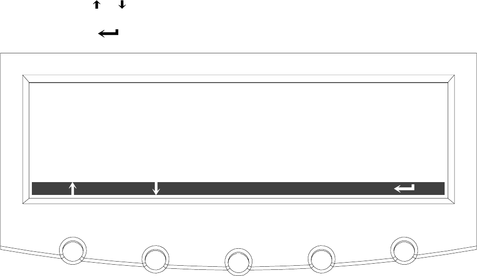
Using the Control Panel
9-40 EATON Powerware®9390 UPS (100–160 kVA) Installation and Operation Manual S164201604 Rev B powerware.com
Select DATE AND TIME from the System Setup Level 1 menu to display the Time Format
Setup screen. The Time Format Setup screen allows the selection of either month/day/year
or day/month/year formats for display on the screen and for logging events in the Event
and History Logs. Figure 9-46 shows the Time Format screen.
Use the or pushbuttons to highlight the desired format, then press the SELECT
pushbutton to display the Set Date and Time screen. To return to the System Setup screen,
press the pushbutton.
MM/DD/YYYY
DD/MM/YYYY
TIME FORMAT SETUP
SELECT
Figure 9-46. Time Format Screen

Using the Control Panel
9-41
EATON Powerware®9390 UPS (100–160 kVA) Installation and Operation Manual S164201604 Rev B powerware.com
The Set Date and Time MM/DD/YYYY screen allows the internal date and time of the UPS
to be set in the month/day/year format. The date and time information is used for display
on the screen and for logging events in the Event and History Logs. Figure 9-47 shows the
Set Date and Time MM/DD/YYYY screen.
Use the or pushbuttons to highlight the setting to be changed. Use the or
pushbuttons to make the change. When finished making changes, use the or
pushbuttons to highlight SAVE and the or pushbuttons to select YES. To complete the
save function and return to the System Setup screen, select the pushbutton.
DATEMONTH YEAR HOUR MINUTE SAVE
2702 2004 15 42 YES
SET DATE AND TIME MM/DD/YYYY
Figure 9-47. Set Date and Time MM/DD/YYYY Screen
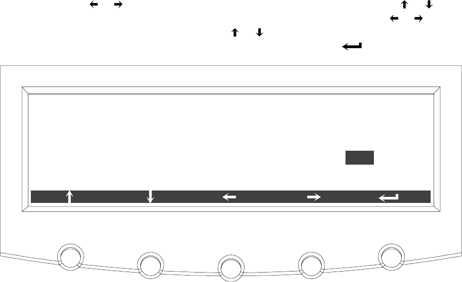
Using the Control Panel
9-42 EATON Powerware®9390 UPS (100–160 kVA) Installation and Operation Manual S164201604 Rev B powerware.com
The Set Date and Time DD/MM/YYYY screen allows the internal date and time of the UPS
to be set in the day/month/year format. The date and time information is used for display
on the screen and for logging events in the Event and History Logs. Figure 9-48 shows the
Set Date and Time DD/MM/YYYY screen.
Use the or pushbuttons to highlight the setting to be changed. Use the or
pushbuttons to make the change. When finished making changes, use the or
pushbuttons to highlight SAVE and the or pushbuttons to select YES. To complete the
save function and return to the System Setup screen, select the pushbutton.
DATE MONTH YEAR HOUR MINUTE SAVE
27 02 2004 15 42 YES
SET DATE AND TIME DD/MM/YYYY
Figure 9-48. Set Date and Time DD/MM/YYYY Screen
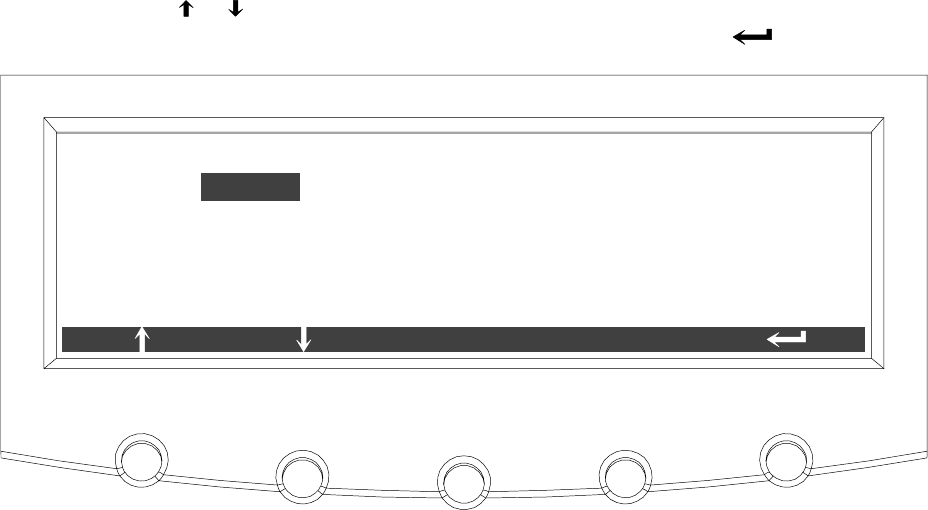
Using the Control Panel
9-43
EATON Powerware®9390 UPS (100–160 kVA) Installation and Operation Manual S164201604 Rev B powerware.com
Select COM PORT SETUP from the System Setup Level 1 menu to display the COM Port
Setup screen. This screen allows selection of the serial COM port to set up. Figure 9-49
shows the COM Port Setup screen.
Use the or pushbuttons to highlight the the COM port to be set up, then press the
SELECT pushbutton. To return to the System Setup screen, press the pushbutton.
COM PORT SETUP
COM 1
COM 3
COM 2
SELECT
Figure 9-49. COM Port Setup Screen
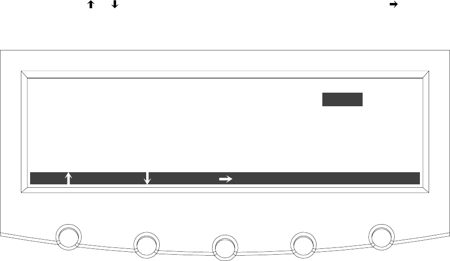
Using the Control Panel
9-44 EATON Powerware®9390 UPS (100–160 kVA) Installation and Operation Manual S164201604 Rev B powerware.com
The COM Setup screen is used to change and save the settings for the serial
communication ports. The COM port number selected from the COM Port Setup screen
displays. If the changes are not wanted, use the ABORT pushbutton to return to the COM
Port Setup screen. Figure 9-50 shows the COM Setup screen.
Use the or pushbuttons to highlight the setting to be changed. Use the pushbutton
to toggle through the values for the setting to make the change. Press SAVE or ABORT.
Once the action is completed, the COM Port Setup screen appears.
BAUD RATE
PARITY
DATA BITS
STOP BITS
19200
NONE
8
1
COM 1 SETUP
ABORT
SAVE
Figure 9-50. COM Setup Screen
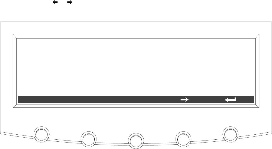
Using the Control Panel
9-45
EATON Powerware®9390 UPS (100–160 kVA) Installation and Operation Manual S164201604 Rev B powerware.com
9.3 System Controls Screen
Press the CONTROLS pushbutton on the main menu bar to display the System Controls
screen. LOAD OFF, normal operation, transfer to bypass, charger control, and power
module startup and shutdown functions are controlled from this screen. In addition, the
screen displays the current status of the UPS and indicates whether the UPS is in
Maintenance Bypass or Bypass, and the state of the power module (PM) and battery
charger. Figure 9-51 and Figure 9-52 show the System Controls screens.
Use the or pushbutton on the menu bar to toggle the menu bar functions between
the two System Controls screens.
MAINTENANCE BYPASS
BYPASS
POWER MODULE (PM)
OFF:
OFF:
ONLINE:
SYSTEM CONTROLS
LOAD OFF BYPASSNORMAL
CHARGER OFF:
Figure 9-51. System Controls Screen 1
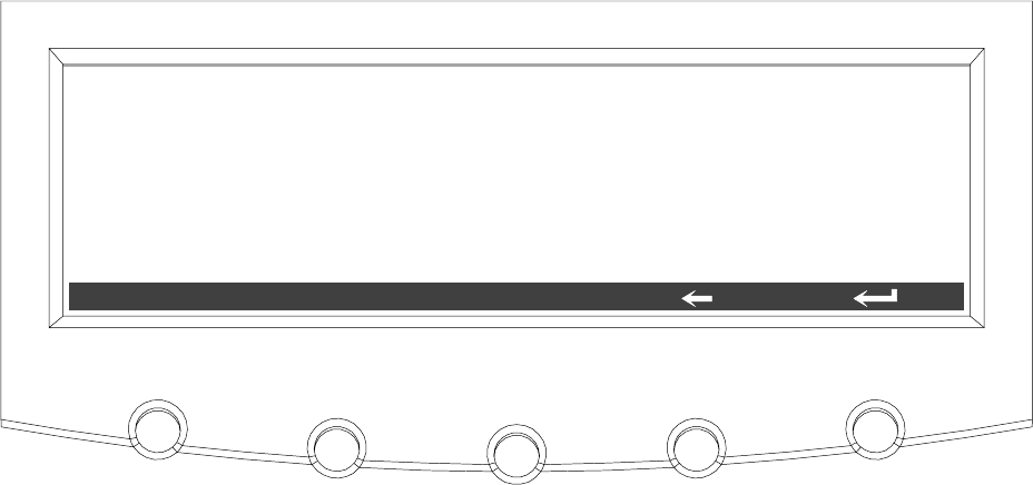
Using the Control Panel
9-46 EATON Powerware®9390 UPS (100–160 kVA) Installation and Operation Manual S164201604 Rev B powerware.com
SYSTEM CONTROLS
LOAD OFF PM OFFCHGR ON
MAINTENANCE BYPASS
BYPASS
POWER MODULE (PM)
OFF:
OFF:
ONLINE:
CHARGER OFF:
Figure 9-52. System Controls Screen 2
The CHGR pushbutton switch toggles the charger function On and Off. The PM pushbutton
switch toggles the power module function On and Off.
For detailed information about using the System Controls, see Chapter 10, “UPS Operating
Instructions.”

Using the Control Panel
9-47
EATON Powerware®9390 UPS (100–160 kVA) Installation and Operation Manual S164201604 Rev B powerware.com
9.4 Load Off Screen
The Load Off screen appears when the LOAD OFF pushbutton is selected from the main
menu bar or System Controls menu bar. This screen allows the LOAD OFF process to be
aborted if the LOAD OFF pushbutton was pressed accidentally. Figure 9-53 shows the Load
Off screen. For detailed information about using the LOAD OFF and Shutdown screens, see
Chapter 10, “UPS Operating Instructions.”
HOLD LOAD OFF BUTTON FOR 3 SECONDS
TO TURN OFF LOAD
LOAD OFFCANCEL
Figure 9-53. Load Off Screen
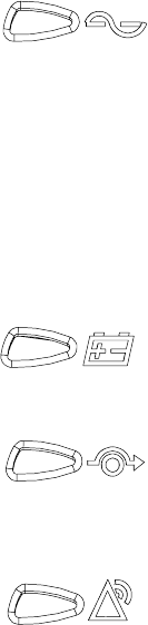
Using the Control Panel
9-48 EATON Powerware®9390 UPS (100–160 kVA) Installation and Operation Manual S164201604 Rev B powerware.com
9.5 Reading the Status Indicators
The four symbols on the right side of the control panel are status indicators.Theyare
colored light emitting diode (LED) lamps, and they work in conjunction with the alarm
horn to let you know the operating status of the UPS.
Normal This green indicator is illuminated when the UPS is operating
in Normal mode. The power module is supplying power to
the critical load.
The indicator flashes when the system needs attention. The
LCD shows all active notices. Some notices may be
accompanied by an audible horn. To silence the horn, press
any control panel pushbutton once. The indicator may be
flashing while other indicators are illuminated. The indicator
continues to flash until acknowledged by pressing any
control panel pushbutton once.
Battery This yellow indicator is illuminated when the UPS is operating
in Battery mode. Because Battery mode is a normal condition
of the UPS, the Normal indicator also remains illuminated.
Bypass This yellow indicator is illuminated when the UPS is operating
in Bypass mode. The critical load is supported by the bypass
source. The Normal indicator is not illuminated when the
system is in Bypass mode.
Alarm This red indicator is illuminated when a situation requires
immediate attention. The LCD shows the highest priority
active alarms. All alarms are accompanied by an audible
horn. To silence the horn, press any control panel
pushbutton once. The Alarm indicator may be illuminated
along with other indicators. The indicator flashes until
acknowledged by pressing any control panel pushbutton
once.
For more information about audible horns, see “System Event Horns” on page 12-1.

10-1
EATON Powerware®9390 UPS (100–160 kVA) Installation and Operation Manual S164201604 Rev B powerware.com
Chapter 10 UPS Operating Instructions
The following procedures provide instructions for operating the UPS or parallel system. For
a description of the UPS control panel functions, see Chapter 9, “Using the Control Panel.”
NOTE Before starting the UPS or parallel system, ensure all installation tasks are
complete and a preliminary startup has been performed by authorized service
personnel. The preliminary startup verifies all electrical interconnections to ensure the
installation was successful and the system operates properly.
NOTE Read this section of the manual and have thorough knowledge of parallel and
UPS operation before attempting to operate any of the controls.
NOTE The UPS displays two minutes of battery runtime at the initial startup. After a
24-hour charging period, the UPS automatically runs a battery test and the correct
battery runtime displays.
10.1SingleModuleOperation
10.1.1 Starting the UPS in Normal Mode
To start the UPS system, perform the following procedure:
1. Close the UPS input feeder circuit breaker.
2. If the UPS is dual feed, close the UPS Bypass input feeder circuit breaker.
3. Observe the UPS control panel display becoming active, indicating logic power.
4. Press the CONTROLS pushbutton on the main menu bar. The System Controls
screen appears.
5. On the System Controls screen, the power module (PM) status should indicate
SHUTDOWN.
6. Press the NORMAL pushbutton on the System Controls menu bar.
If Auto Bypass is enabled, the critical load is immediately supplied by the bypass
source, in Bypass mode, until the inverter turns on and the UPS transfers to
Normal mode. The status indicator on the UPS control panel indicates the UPS is
inBypassmode.IfAutoBypassisnotenabled,theUPSoutputremainsoffuntil
the UPS transfers to Normal mode.

UPS Operating Instructions
10-2 EATON Powerware®9390 UPS (100–160 kVA) Installation and Operation Manual S164201604 Rev B powerware.com
7. Observe the following messages appear sequentially on the power module (PM)
status line:
DC STARTING
INVERTER STARTING
INVERTER SYNCING
READY
ONLINE
The rectifier and inverter turn on. The inverter continues to ramp up to full
voltage.
8. Close the battery breaker any time after INVERTER SYNCING or CLOSE BATTERY
appears on the display.
Once the inverter reaches full voltage, and the battery breaker is closed, the UPS
output contactor K3 closes and the static switch turns off. Power is now supplied
to the critical load in Normal mode. It takesapproximately1minutefortheUPS
to achieve Normal mode.
9. The UPS is now operating in Normal mode and the NORMAL status indicator is
illuminated.
10.1.2 Starting the UPS in Bypass Mode
IftheinverteroutputoftheUPSisnotavailableandthecriticalloadneedstobe
energized, perform the following procedure:
CAUTION
In Bypass mode, the critical load is not protected from commercial power interruptions and
abnormalities.
1. Close the UPS input feeder circuit breaker.
2. If the UPS is dual feed, close the UPS Bypass input feeder circuit breaker.
3. Observe the UPS control panel becoming active, indicating logic power.
4. Press the CONTROLS pushbutton on the main menu bar. The System Controls
screen appears.
5. On the System Controls screen, the power module (PM) status should indicate
SHUTDOWN.
6. Press the BYPASS pushbutton on the System Controls menu bar.
The critical load is immediately supplied by the bypass source, in Bypass mode.
7. The UPS is now operating in Bypass mode and the BYPASS status indicator is
illuminated.

UPS Operating Instructions
10-3
EATON Powerware®9390 UPS (100–160 kVA) Installation and Operation Manual S164201604 Rev B powerware.com
10.1.3 Starting the Power Module
To start the power module without transferring the critical load to normal, perform the
following procedure:
1. Close the UPS input feeder circuit breaker.
2. If the UPS is dual feed, close the UPS Bypass input feeder circuit breaker.
3. Observe the UPS control panel becoming active, indicating logic power.
4. Press the CONTROLS pushbutton on the main menu bar. The System Controls
screen appears.
5. On the System Controls screen, the power module (PM) status should indicate
SHUTDOWN.
6. Press the pushbutton to display System Controls Screen 2.
7. Press the PM ON pushbutton on the System Controls menu bar.
8. Observe the following messages appear sequentially on the power module (PM)
status line:
DC STARTING
INVERTER STARTING
INVERTER SYNCING
READY
The rectifier and inverter turn on. When the inverter reaches full voltage, the UPS
is ready to transfer to the Normal mode and supply the critical load.
10.1.4 Transfer from Normal to Bypass Mode
To transfer the critical load to Bypass mode, perform the following procedure:
CAUTION
In Bypass mode, the critical load is not protected from commercial power interruptions and
abnormalities.
1. Press the CONTROLS pushbutton on the main menu bar. The System Controls
screen appears.
2. Press the BYPASS pushbutton on the System Controls menu bar.
TheUPStransferstoBypassmodeandthecriticalloadisimmediatelysuppliedby
the bypass source. If the bypass source is not available, the power processor
remains on and an alarm sounds.

UPS Operating Instructions
10-4 EATON Powerware®9390 UPS (100–160 kVA) Installation and Operation Manual S164201604 Rev B powerware.com
3. The UPS is now operating in Bypass mode and the BYPASS status indicator is
illuminated.
The power module (PM) status indicates READY. The system is now on bypass and
the UPS power processor remains on.
WARNING
Power is present inside the UPS cabinets.
10.1.5 Transfer from Bypass to Normal Mode
To transfer the critical load to Normal mode, perform the following procedure:
1. Press the CONTROLS pushbutton on the main menu bar. The System Controls
screen appears.
2. Press the NORMAL pushbutton on the System Controls menu bar.
The UPS transfers to Normal mode. If the power processor is not available, the
system remains on bypass and an alarm sounds.
3. The UPS is now operating in Normal mode, and the NORMAL status indicator is
illuminated.
The power module (PM) status indicates ONLINE.
10.1.6 Transfer from Normal to Bypass Mode and Shut Down UPS
To transfer the critical load to Bypass mode and shut down the UPS, perform the following
procedure:
1. Transfer the critical load to bypass by performing the procedure in
paragraph 10.1.4.
2. Press the CONTROLS pushbutton on the main menu bar. The System Control
screen appears.
3. Press the pushbutton to display System Controls Screen 2.
4. Press the PM OFF pushbutton on the System Controls menu bar.
The power module (PM) status indicates SHUTDOWN.The input and output
contactors open, the battery breaker or disconnect is tripped, and the power
moduleisturnedoff.Thebypasssourcesuppliesthecriticalload.
WARNING
Power is present inside the UPS cabinets.

UPS Operating Instructions
10-5
EATON Powerware®9390 UPS (100–160 kVA) Installation and Operation Manual S164201604 Rev B powerware.com
10.1.7 UPS and Critical Load Shutdown
To perform maintenance or service on the critical load, shut down power to the load by
performing the following procedure:
1. Turn off all equipment that is being powered by the UPS.
2. Perform the LOAD OFF procedure in paragraph 10.1.9.
The input, output, and bypass backfeed contactors open, the battery breaker or
disconnect is tripped, and the power module is turned off.
WARNING
Power is present inside the UPS cabinet until the upstream input feeder circuit breaker is
opened.
3. Open the UPS input and bypass (if dual feed) feeder circuit breakers.
10.1.8 Charger Control
To turn the battery charger on or off, perform the following procedure:
1. Press the CONTROLS pushbutton on the main menu bar. The System Control
screen appears.
2. Press the pushbutton to display System Controls Screen 2.
3. Press the CHGR ON or CHGR OFF pushbutton on the System Controls menu bar
to toggle the charger on or off.

UPS Operating Instructions
10-6 EATON Powerware®9390 UPS (100–160 kVA) Installation and Operation Manual S164201604 Rev B powerware.com
10.1.9 Using the UPS LOAD OFF Pushbutton
AUPSLoadOffisinitiatedbytheLOAD OFF pushbutton from the main menu bar or the
System Controls menu bar. This pushbutton can be pressed to control the UPS output. The
UPS LOAD OFF pushbutton de-energizes the critical load and powers down the UPS.
The UPS (including Bypass) remains off until restarted.
To use the LOAD OFF pushbutton:
1. Press the LOAD OFF pushbutton.
The Load Off screen appears, providing a choice to proceed or abort the
shutdown.
CAUTION
All power to the critical load is lost when the LOAD OFF is selected in the following step. You
should use this feature only when you want to de-energize the critical load.
2. To shut down the UPS, press LOAD OFF from the Load Off menu bar, and hold for
three seconds. To abort the shutdown, press CANCEL.
When LOAD OFF is selected and held for three seconds, the input, output, and
bypass backfeed contactors open, the battery breaker or disconnect is tripped,
and the power module is turned off.
CAUTION
Do not attempt to restart the system after Load Off until the cause of the shutdown has been
identified and cleared.
3. To restart the UPS after pressing the LOAD OFF pushbutton, follow the procedure
in paragraph 10.1.1 or 10.1.2.

UPS Operating Instructions
10-7
EATON Powerware®9390 UPS (100–160 kVA) Installation and Operation Manual S164201604 Rev B powerware.com
10.1.10 Using the Remote Emergency Power-off Switch
A UPS emergency power-off is initiated by the REPO pushbutton switch. In an emergency,
you can use this switch to control the UPS output. The REPO switch de-energizes the
critical load and powers down the UPS immediately, without asking for verification.
The UPS, including Bypass, remains off until restarted.
CAUTION
All power to the critical load is lost when the REPO switch is activated in the following step.
You should use this feature only when you want to de-energize the critical load.
NOTE The following instructions are for the Powerware-supplied REPO switch. If a
customer-supplied REPO switch is used, it may not activate in the same manner; refer
to the operating instructions provided with the switch.
To use the REPO switch:
1. Press the REPO pushbutton switch.
The input, output, and bypass backfeed contactors open, the battery breaker or
disconnect is tripped, and the power module is turned off immediately, without
asking for verification.
CAUTION
Do not attempt to restart the system after Load Off until the cause of the shutdown has been
identified and cleared.
2. To restart the UPS after using the REPO pushbutton, reset the REPO switch and
then follow the procedure in paragraph 10.1.1 or 10.1.2.
UPS Operating Instructions
10-8 EATON Powerware®9390 UPS (100–160 kVA) Installation and Operation Manual S164201604 Rev B powerware.com
10.2 Multiple Module Parallel Operation
10.2.1 Starting the Parallel System in Normal Mode
To start the parallel system, perform the following procedure:
1. Close all uninterruptible power module input feeder circuit breakers.
2. If the UPMs are dual feed, close all UPM Bypass input feeder circuit breakers.
3. Observe all UPM control panel displays becoming active, indicating logic power.
4. Press the CONTROLS pushbutton on the main menu bar of any UPM. The System
Controls screen appears on each UPM.
5. On the System Controls screen of each UPM, the power module (PM) status
should indicate SHUTDOWN.
6. Press the NORMAL pushbutton on the System Controls menu bar of any UPM.
If Auto Bypass is enabled, the critical load is immediately supplied by the bypass
source, in Bypass mode, until the inverters turn on and the UPMs transfer to
Normal mode. The status indicator on each UPM control panel indicates the UPM
isinBypassmode.IfAutoBypassisnotenabled,theUPMoutputsremainoffuntil
theUPMstransfertoNormalmode.
7. Observe the following messages appear sequentially on the power module (PM)
status line of each UPM:
DC STARTING
INVERTER STARTING
INVERTER SYNCING
READY
ONLINE
The rectifier and inverter turn on. The inverter continues to ramp up to full
voltage.
8. Close the battery breakers for each UPM any time after INVERTER SYNCING or
CLOSE BATTERY appears on the display.
Once the inverter reaches full voltage, and the battery breaker is closed, each UPM
output contactor K3 closes and each static switch turns off. Power is now supplied
to the critical load in Normal mode. It takesapproximately1minutefortheUPMs
to achieve Normal mode.
9. The UPMs are now operating in Normal mode and the NORMAL status indicator
on each UPM is illuminated.

UPS Operating Instructions
10-9
EATON Powerware®9390 UPS (100–160 kVA) Installation and Operation Manual S164201604 Rev B powerware.com
10.2.2 Starting the Parallel System in Bypass Mode
If the inverter output of the UPMs is not available and the critical load needs to be
energized, perform the following procedure:
CAUTION
In Bypass mode, the critical load is not protected from commercial power interruptions and
abnormalities.
1. Close all UPM input feeder circuit breakers.
2. If the UPMs are dual feed, close all UPM Bypass input feeder circuit breakers.
3. Observe all UPM control panel displays becoming active, indicating logic power.
4. Press the CONTROLS pushbutton on the main menu bar of any UPM. The System
Controls screen appears on each UPM.
5. On the System Controls screen of each UPM, the power module (PM) status
should indicate SHUTDOWN.
6. Press the BYPASS pushbutton on the System Controls menu bar of any UPM.
The critical load is immediately supplied by the bypass source, in Bypass mode.
7. The UPMs are now operating in Bypass mode and the BYPASS status indicator on
each UPM is illuminated.

UPS Operating Instructions
10-10 EATON Powerware®9390 UPS (100–160 kVA) Installation and Operation Manual S164201604 Rev B powerware.com
10.2.3 Transfer Parallel System from Normal to Bypass Mode
To transfer the critical load to Bypass mode, perform the following procedure:
CAUTION
In Bypass mode, the critical load is not protected from commercial power interruptions and
abnormalities.
1. Press the CONTROLS pushbuttononthemainmenubaronanyUPM.TheSystem
Controls screen appears.
2. Press the BYPASS pushbutton on the System Controls menu bar of any UPM.
TheUPMstransfertoBypassmodeandthecriticalloadisimmediatelysuppliedby
the bypass source. If the bypass source is not available, the power processor
remains on and an alarm sounds.
3. The UPMs are now operating in Bypass mode and the BYPASS status indicator on
each UPM is illuminated.
The power module (PM) status indicates READY on each UPM. The system is
now on bypass and the UPM power processors remain on.
WARNING
Power is present inside the UPM cabinets.
10.2.4 Transfer Parallel System from Bypass to Normal Mode
To transfer the critical load to Normal mode, perform the following procedure:
1. Press the CONTROLS pushbuttononthemainmenubaronanyUPM.TheSystem
Control screen appears.
2. Press the NORMAL pushbutton on the System Controls menu bar of any UPM.
The UPMs transfer to Normal mode. If the power processor is not available, the
system remains on bypass and an alarm sounds.
3. The UPMs are now operating in Normal mode, and the NORMAL status indicator
on each UPM is illuminated.
The power module (PM) status indicates ONLINE on each UPM.

UPS Operating Instructions
10-11
EATON Powerware®9390 UPS (100–160 kVA) Installation and Operation Manual S164201604 Rev B powerware.com
10.2.5 Single UPM Shutdown
To shut down a single UPM, perform the following procedure:
NOTE The UPM can be shut down only if remaining UPMs can support the critical
load without being overloaded.
1. Press the CONTROLS pushbutton on the main menu bar on the UPM to be shut
down. The System Controls screen appears.
2. Press the pushbutton to display System Controls Screen 2.
3. Press the PM OFF pushbutton on the System Controls menu bar.
The power module (PM) status indicates SHUTDOWN. The input and output
contactors open, the battery breaker or disconnect is tripped, and the power
module is turned off.
4. Open the input and bypass (if dual feed) feeder circuit breakers supplying the
shutdown UPM.
NOTE The monitor screen continues to be active until the UPM is isolated from the
critical bus.
WARNING
Power is present inside the shutdown UPM cabinet due to connection to the critical bus, until
the UPM output breaker is opened.
5. If it is necessary to isolate the UPM from the critical bus, open the module output
breaker on the tie cabinet or distribution panel.
10.2.6 Restarting a Single UPM
To restart a single UPM, perform the following procedure:
1. IftheUPMwasisolatedfromthecriticalbus,closethemoduleoutputbreakeron
the tie cabinet or distribution panel.
2. Observe the UPM control panel display becoming active, indicating logic power.
UPM logic is being powered from the critical bus.
3. Close the UPM input feeder circuit breaker.
4. If the UPM is dual feed, close the UPM Bypass input feeder circuit breaker.
5. Press the CONTROLS pushbutton on the main menu bar of the UPM. The System
Controls screen appears.
6. On the System Controls screen, the power module (PM) status should indicate
SHUTDOWN.

UPS Operating Instructions
10-12 EATON Powerware®9390 UPS (100–160 kVA) Installation and Operation Manual S164201604 Rev B powerware.com
7. Press the NORMAL pushbutton on the System Controls menu bar of the UPM.
8. Observe the following messages appear sequentially on the power module (PM)
status line of the UPM:
DC STARTING
INVERTER STARTING
INVERTER SYNCING
READY
ONLINE
The rectifier and inverter turn on. When the inverter reaches full voltage, the UPM
synchronizes with the output and closes output contactor K3. The UPM is online
and in Normal mode with the NORMAL status indicator illuminated and in parallel
with the other system UPMs.
9. Close battery breakers for the UPM any time after INVERTER SYNCING or CLOSE
BATTERY appears on the display.
10.2.7 Parallel System and Critical Load Shutdown
To perform maintenance or service on the critical load, shut down power to the load by
performing the following procedure:
CAUTION
Using the following procedure removes all output from the critical load. You should use this
procedure only when you need to de-energize both the parallel system and the critical load.
1. Turn off all equipment that is being powered by the parallel system.
2. Press the CONTROLS pushbuttononthemainmenubaronanyUPM.TheSystem
Controls screen appears.
3. Press the BYPASS pushbutton on the System Controls menu bar of any UPM.
TheUPMstransfertoBypassmode.
4. Press the pushbutton to display System Controls Screen 2.
5. Press the PM OFF pushbutton on the System Controls menu bar.
The power module (PM) status indicates SHUTDOWN.The input and output
contactors open, the battery breaker or disconnect is tripped, and the power
moduleisturnedoff.Thebypasssourcesuppliesthecriticalload.
6. Repeat Steps 2, 4, and 5 for each UPM, except the last UPM

UPS Operating Instructions
10-13
EATON Powerware®9390 UPS (100–160 kVA) Installation and Operation Manual S164201604 Rev B powerware.com
7. To shut down the last UPM, press the REPO pushbutton switch. See “Using the
Parallel System Remote Emergency Power-off Switch” in paragraph 10.2.9.
The input, output, and bypass backfeed contactors open, the battery breaker or
disconnect is tripped, and the power module is turned off immediately, without
asking for verification.
8. Open all UPM input and bypass (if dual feed) feeder circuit breakers.
The parallel system and critical load is now de-energized.
9. To restart the parallel system after using the REPO pushbutton, reset the REPO
switch and then follow the procedure in paragraph 10.2.1 or 10.2.2.
10.2.8 Using the UPS LOAD OFF Pushbutton
NOTE The UPM LOAD OFF pushbutton controls only the UPM on which Load Off was
activated and only interrupts the ability of that module to deliver power to the critical
bus. The redundant modules continue to support the critical load.The UPM can be shut
down only if the remaining UPMs can support the critical load without being
overloaded. To remove all power from the critical load, use the REPO pushbutton.
AUPSLoadOffisinitiatedbytheLOAD OFF pushbutton from the main menu bar or the
System Controls menu bar. The UPS LOAD OFF pushbutton de-energizes the critical load
and powers down the UPS.
The UPS (including Bypass) remains off until restarted.
To use the LOAD OFF pushbutton:
1. Press the LOAD OFF pushbutton.
The Load Off screen appears, providing a choice to proceed or abort the
shutdown.
CAUTION
All power to the critical load is lost when the LOAD OFF is selected in the following step. You
should use this feature only when you want to de-energize the critical load.
2. To shut down the UPS, press LOAD OFF from the Load Off menu bar, and hold for
three seconds. To abort the shutdown, press CANCEL.
When LOAD OFF is selected and held for three seconds, the input, output, and
bypass backfeed contactors open, the battery breaker or disconnect is tripped,
and the power module is turned off.

UPS Operating Instructions
10-14 EATON Powerware®9390 UPS (100–160 kVA) Installation and Operation Manual S164201604 Rev B powerware.com
CAUTION
Do not attempt to restart the system after Load Off until the cause of the shutdown has been
identified and cleared.
3. To restart the UPS after pressing the LOAD OFF pushbutton, follow the procedure
in paragraph 10.2.1 or 10.2.2.
10.2.9 Using the Parallel System Remote Emergency Power-off Switch
A parallel system emergency power-off is initiated by the REPO pushbutton switch. In an
emergency, you can use this switch to control the UPM outputs. The REPO switch
de-energizes the critical load and powers downtheUPMsimmediately,withoutaskingfor
verification.
The UPMs, including Bypass, remain off until restarted.
CAUTION
All power to the critical load is lost when the REPO switch is activated in the following step.
You should use this feature only when you want to de-energize the critical load.
NOTE The following instructions are for the Powerware-supplied REPO switch. If a
customer-supplied REPO switch is used, it may not activate in the same manner; refer
to the operating instructions provided with the switch.
To use the REPO switch:
1. Press the REPO pushbutton switch.
The input, output, and bypass backfeed contactors open, the battery breaker or
disconnect is tripped, and the power module is turned off immediately, without
asking for verification.
CAUTION
Do not attempt to restart the system after Load Off until the cause of the shutdown has been
identified and cleared.
2. To restart the UPMs after using the REPO pushbutton, reset the REPO switch and
then follow the procedure in paragraph 10.2.1 or 10.2.2.

11-1
EATON Powerware®9390 UPS (100–160 kVA) Installation and Operation Manual S164201604 Rev B powerware.com
Chapter 11 Using Features and Options
The many standard features of your UPS system provide consistent, economical, and
dependable power protection. In addition, you can add available options to enhance the
performance of your system. This chapter provides descriptions of some of the features
and options introduced earlier in this manual. For location of the customer interface panel
and terminals and for terminal wiring information, see:
쑺Drawing 164201604-6 on page A-27
쑺Drawing 164201604-8 starting on page A-33
11.1 Building Alarm Monitoring
This standard feature lets you connect the UPS to your building alarms, such as smoke
detectors or overtemperature alarms. The customer interface terminals for external
connections are located inside the UPS. You should use twisted-pair wires for each alarm
input and common.
The building alarms can be programmed to display the alarm functional name.
11.2 General Purpose Relay Contact
One general purpose relay contact is provided as a standard feature on the UPS. The alarm
contact is located inside the UPS on the customer interface terminal board.
You can use a normally-closed or normally-open contact. If the state of the contact
changes from the state you specify as normal, a signal is issued. You can connect this
contact to equipment at your facility (such as a light or an alarm bell) to let you know
whenanalarmisactiveontheUPS.ThisfeatureisusefuliftheUPSislocatedinaremote
area where the UPS horn may not be heard immediately.
CAUTION
Contacts should not be operated in excess of 120 Vac @ 5A maximum.
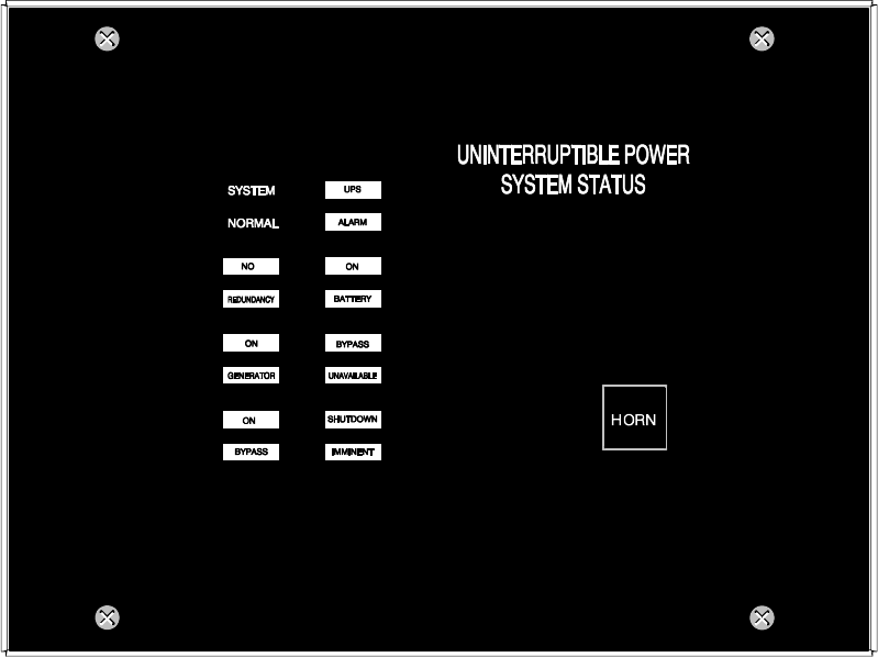
Using Features and Options
11-2 EATON Powerware®9390 UPS (100–160 kVA) Installation and Operation Manual S164201604 Rev B powerware.com
11.3 Optional Remote Monitor Panel II
As an option, a Remote Monitor Panel II (RMP II) can be installed to monitor the operation
of the UPS system from virtually any location within the facility, up to 152.4m (500 ft) from
the UPS. The RMP II contains backlit status indicators and a local horn. The RMP II can be
flush-mounted or surface-mounted on a desktop, or secured to a wall. Figure 11-1 shows
an RMP II.
Figure 11-1. Remote Monitor Panel II
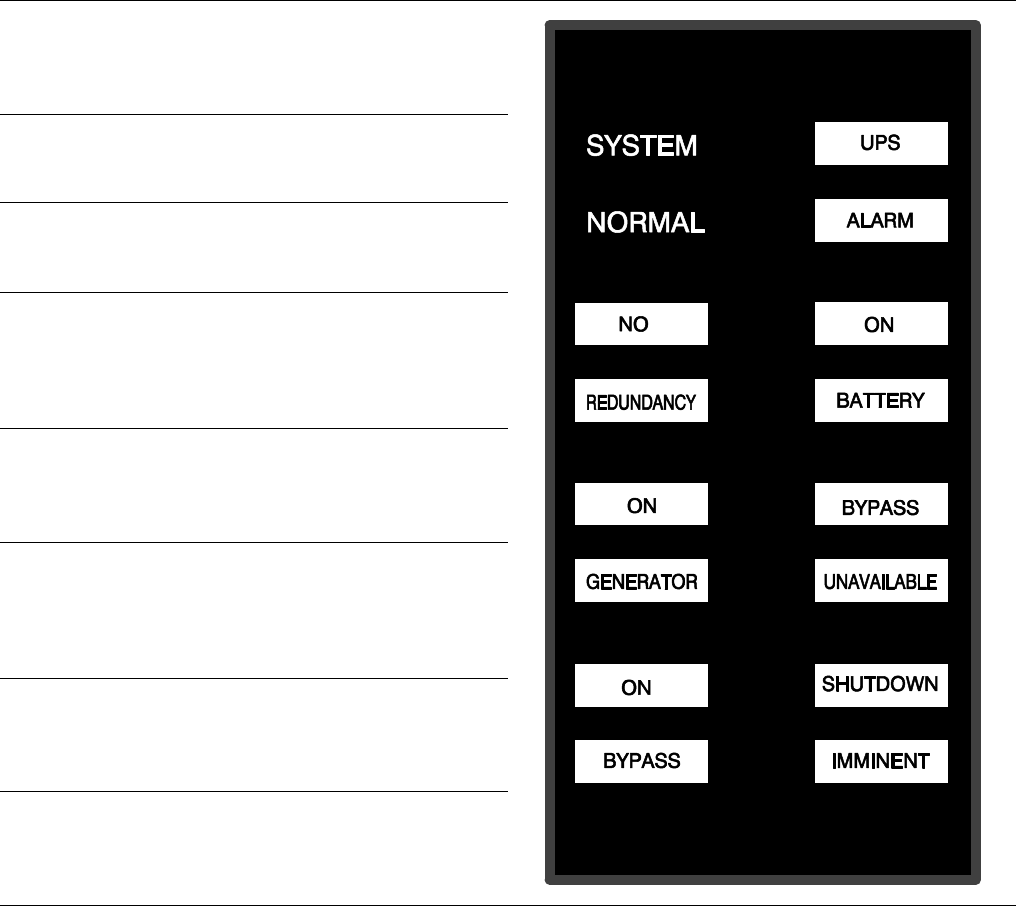
Using Features and Options
11-3
EATON Powerware®9390 UPS (100–160 kVA) Installation and Operation Manual S164201604 Rev B powerware.com
The RMP II contains a local horn and the backlit status indicators listed in Table 11-1.
Table 11-1. RMP II Status Indicators
SYSTEM NORMAL
The UPS is energized (either with utility power or battery
backup) and is supplying conditioned power to the
critical load.
NO REDUNDANCY
This indicator applies only to parallel systems when one
cabinet is not functioning.
ON GENERATOR
The UPS input and bypass are being supplied by the power
from the generator instead of from the utility power.
ON BYPASS
Thebypasssourceissupplyingthecriticalload.Usually
thismeansthattheUPSisnotenergized.Theloadisnot
protected in Bypass mode, and a horn sounds after
30 seconds.
UPS ALARM
The UPS system is issuing an alarm. Conditions that
affect the current UPS mode are indicated by the
indicatorsandhornontheUPS.
ON BATTERY
The UPS battery backup is supplying the critical load.
The utility power is either interrupted or out of
specification. The SYSTEM NORMAL indicator is also
illuminated.
BYPASS UNAVAILABLE
The UPS system is in Normal mode, but a bypass source
is not within specification. A horn sounds after
30 seconds.
SHUTDOWN IMMINENT
The UPS is preparing to shut down because the UPS is in
Battery mode and the DC voltage is approaching its low
limit. This indicator is accompanied by a horn.
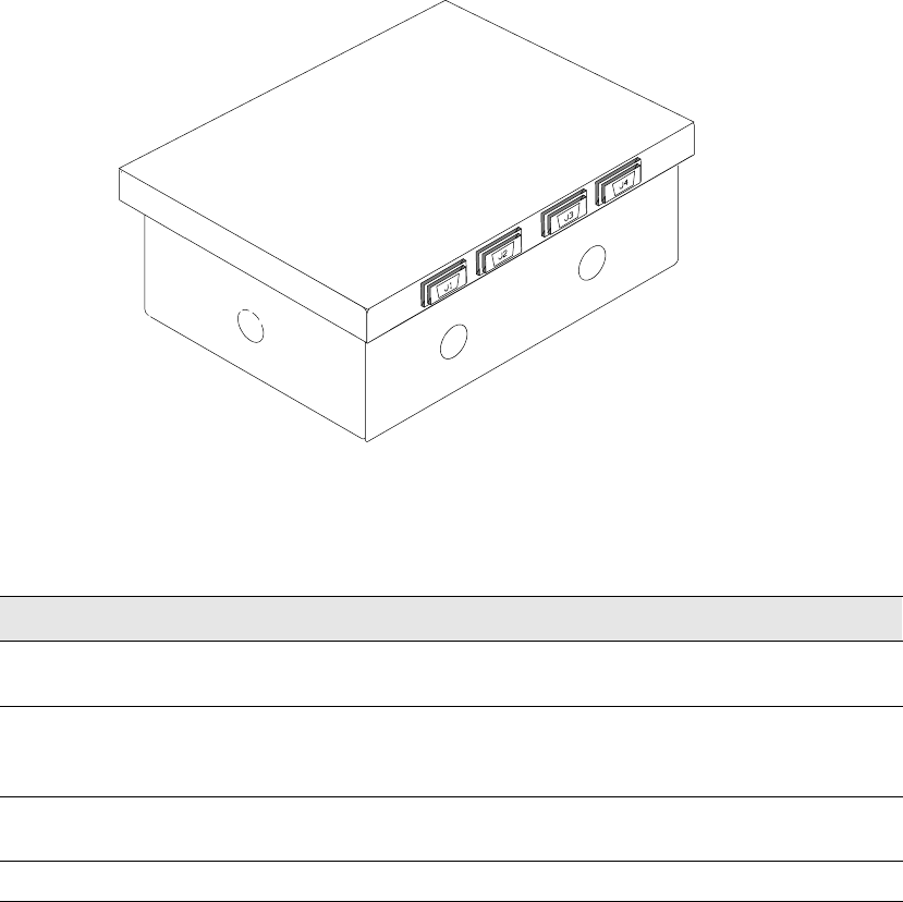
Using Features and Options
11-4 EATON Powerware®9390 UPS (100–160 kVA) Installation and Operation Manual S164201604 Rev B powerware.com
11.4 Relay Interface Module II
An optional RIM II uses relay contact closures to indicate the operating status and alarm
condition of the UPS system. The RIM II can be flush-mounted or surface-mounted on a
desktop, or secured to a wall. Figure 11-2 shows the RIM II with its four 15-pin connectors
labeled J1 through J4.
Figure 11-2. Relay Interface Module II
The RIM II can provide the status and alarm signals shown in Table 11-2.
Table 11-2. Customer Interface Connectors
Status J1 through J4 Description
UPS AVAILABLE Pins 1 and 12 Contacts are closed when the UPS is operating in
Normal mode or ready to supply the load.
UPS OFFLINE Pins 3 and 13 Contacts are open when the UPS is offline.
Contacts are closed when the UPS is operating in
Normal mode.
BATTERY WEAK Pins 5 and 14 Contacts are closed when approximately two minutes of
battery time is remaining, before the critical load is lost.
UTILITY FAILURE Pins 6 and 15 Contacts are closed when Utility Failure is detected.
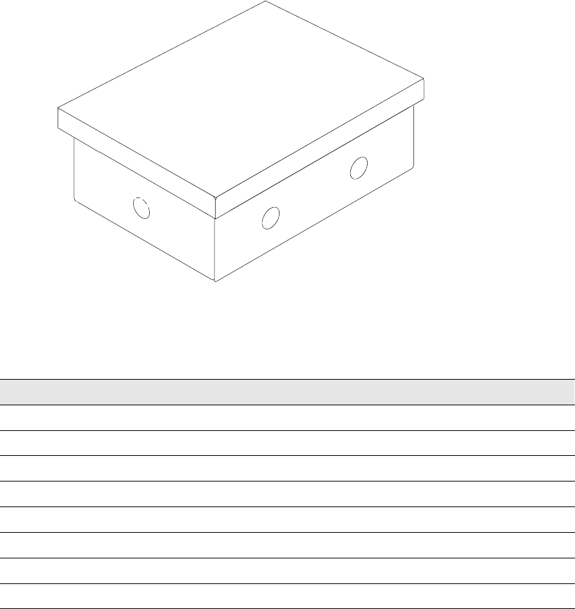
Using Features and Options
11-5
EATON Powerware®9390 UPS (100–160 kVA) Installation and Operation Manual S164201604 Rev B powerware.com
11.5 Supervisory Contact Module II
An optional SCM II establishes an interface between the UPS system and the customer’s
monitor. This interface allows the customer to monitor operational status of the UPS
system equipment. The SCM II can be flush-mounted or surface-mounted on a desktop, or
secured to a wall. Figure 11-3 shows the SCM II.
Figure 11-3. Supervisory Contact Module II
TheSCMIIprovidessignalsfortheindicationsshowninTable11-3.
Table 11-3. SCM II Status Indicators and Connections
Indication TB-2 Connections
SYSTEM NORMAL TB2-1 through TB2-3
NO REDUNDANCY TB2-4 through TB2-6
ON GENERATOR TB2-7 through TB2-9
BYPASS NOT AVAILABLE TB2-10 through TB2-12
ON BATTERY TB2-13 through TB2-15
UPS ALARM TB2-16 through TB2-18
ON BYPASS TB2-19 through TB2-21
SHUTDOWN IMMINENT TB2-22 through TB2-24
Using Features and Options
11-6 EATON Powerware®9390 UPS (100–160 kVA) Installation and Operation Manual S164201604 Rev B powerware.com
This page intentionally left blank.

12-1
EATON Powerware®9390 UPS (100–160 kVA) Installation and Operation Manual S164201604 Rev B powerware.com
Chapter 12 Responding to System Events
12.1 General
When the UPS system is running in Normal mode, it continually monitors itself and the
incoming utility power. In Battery or Bypass modes, the UPS may issue alarms to let you
know exactly what event caused the change from Normal mode. System events on the UPS
can be indicated by horns, lights, messages, or all three.
Select Events fromthemenubarontheMainMenuscreen to look at the Active System
Events screen. This screen shows any currently active alarms, notices, or commands. For
more information on using the Events screen, see paragraph 9.2.2, “Event Screens.”
12.2 System Event Horns
The system event horn beeps to alert an operator that an event needing attention is taking
place. Horn 1 cycles at a one-second rate.
12.3 System Event Indicators
ThestatusindicatorsontheUPScontrolpanel work in conjunction with the event horn to
let you know when the UPS system is operating in any mode other than Normal. Only the
Normal indicator is visible during normal UPS system operation. The other indicators
illuminate to indicate alarms or events. When an alarm occurs, you should first check these
indicators to see what type of event has taken place. For descriptions of the status
indicators, see paragraph 9.5, “Reading the Status Indicators.”
12.4 System Event Messages
When a system event occurs, a message appears on the LCD in the UPS status area. This
message is also written to the Active Events log and may be added to the Events History
log. The messages are divided into four categories: alarms, notices, status, and commands.
The following tables contain the events displayed on the Events screen of the control
panel.

Responding to System Events
12-2 EATON Powerware®9390 UPS (100–160 kVA) Installation and Operation Manual S164201604 Rev B powerware.com
ALARMS
Message Horn Phone Relay Log* Indication
Battery Totally Discharged 1No 1HA Shutdown Imminent
Battery Totally Discharged OK Off No 1HA Condition Cleared
Building Alarm 1 1No 1HA User Action Required
Building Alarm 1 OK Off No 1HA Condition Cleared
Building Alarm 2 1No 1HA User Action Required
Building Alarm 2 OK Off No 1HA Condition Cleared
Check Bypass 1 1 1 HA Service Required
Check Bypass OK Off No 1HA Condition Cleared
Check Bypass Switchgear 1No 1HA Service Required
Check Bypass Switchgear OK Off No 1HA Condition Cleared
Check Charger 1 1 1 HA Service Required
Check Charger OK Off No 1HA Condition Cleared
Check Fan 1No 1HA Service Required
Check Fan OK Off No 1HA Condition Cleared
Check Input Switchgear 1 1 1 HA Service Required
Check Input Switchgear OK Off No 1HA Condition Cleared
Check Inv Temperature Sensor 1No 1HA Service Required
Check Inv Temperature Sensor OK Off No 1HA Condition Cleared
Check Inverter 1 1 1 HA Service Required
Check Logic Power Supply 1No 1HA Service Required
Check Logic Power Supply OK Off No 1HA Condition Cleared
Check Output Switchgear 1No 1HA Service Required
Check Output Switchgear OK Off No 1HA Condition Cleared
Check Power Supply 1 1 1 HA Service Required
Check Power Supply OK Off No 1HA Condition Cleared
Check Precharge 1No 1HA Service Required
Check Precharge OK Off No 1HA Condition Cleared
Check Rect Temperature Sensor 1No 1HA Service Required
Check Rect Temperature Sensor OK Off No 1HA Condition Cleared
Check Rectifier 1 1 1 HA Service Required
Check Static Switch 1 1 1 HA Service Required
Check Static Switch OK Off No 1HA Condition Cleared
Close Battery Switchgear 1 1 1 HA User Action Required
Close Battery Switchgear OK Off No 1HA Condition Cleared
*Log codes indicate where the UPS records the event: H = History log; HA = History and Active logs; and
A=Activelogonly.

Responding to System Events
12-3
EATON Powerware®9390 UPS (100–160 kVA) Installation and Operation Manual S164201604 Rev B powerware.com
ALARMS
Indication
Log*RelayPhoneHorn
Message
Configuration Error 1No 1HA Service Required
Configuration Error OK Off No 1HA Condition Cleared
External Comm Failure 1No 1HA Service Required
External Comm Failure OK Off No 1HA Condition Cleared
Internal Comm Failure 1No 1HA Service Required
Internal Comm Failure OK Off No 1HA Condition Cleared
Invalid Board ID 1No 1HA Service Required
Invalid Board ID OK Off No 1HA Condition Cleared
Inverter L1 Current Limit 1No 1HA Service Required
Inverter L2 Current Limit 1No 1HA Service Required
Inverter L3 Current Limit 1No 1HA Service Required
Inverter Output Failure 1 1 1 HA Service Required
Inverter Output Failure OK Off No 1HA Condition Cleared
Inverter Overtemperature 1No 1HA Service Required
Inverter Overtemperature OK Off No 1HA Condition Cleared
Inverter Overtemperature Trip 1No 1HA Service Required
Inverter Overtemperature Trip OK Off No 1HA Condition Cleared
L1 Overload 1No 1HA User Action Required
L1 Overload OK Off No 1HA Condition Cleared
L1 Overload (Extreme Level) 1No 1HA User Action Required
L1 Overload (Extreme Level) OK Off No 1HA Condition Cleared
L1 Overload (High Level) 1No 1HA User Action Required
L1 Overload (High Level) OK Off No 1HA Condition Cleared
L2 Overload 1No 1HA User Action Required
L2 Overload OK Off No 1HA Condition Cleared
L2 Overload (Extreme Level) 1No 1HA User Action Required
L2 Overload (Extreme Level) OK Off No 1HA Condition Cleared
L2 Overload (High Level) 1No 1HA User Action Required
L2 Overload (High Level) OK Off No 1HA Condition Cleared
L3 Overload 1No 1HA User Action Required
L3 Overload OK Off No 1HA Condition Cleared
L3 Overload (Extreme Level) 1No 1HA User Action Required
L3 Overload (Extreme Level) OK Off No 1HA Condition Cleared
*Log codes indicate where the UPS records the event: H = History log; HA = History and Active logs; and
A=Activelogonly.

Responding to System Events
12-4 EATON Powerware®9390 UPS (100–160 kVA) Installation and Operation Manual S164201604 Rev B powerware.com
ALARMS
Indication
Log*RelayPhoneHorn
Message
L3 Overload (High Level) 1No 1HA User Action Required
L3 Overload (High Level) OK Off No 1HA Condition Cleared
Low Battery Shutdown 1No 1HA User Action Required
Low Battery Shutdown OK Off No 1HA Condition Cleared
Not Enough UPMs 1No 1HA User Action Required
Not Enough UPMs OK Off No 1HA Condition Cleared
Output Overload 1No 1HA User Action Required
Output Overload OK Off No 1HA Condition Cleared
Output Watts Overload 1No 1HA User Action Required
Output Watts Overload OK Off No 1HA Condition Cleared
Parallel System Overload 1No 1HA User Action Required
Parallel System Overload OK Off No 1HA Condition Cleared
Rect Overtemperature Trip 1No 1HA Service Required
Rect Overtemperature Trip OK Off No 1HA Condition Cleared
Rectifier Overtemperature 1No 1HA Service Required
Rectifier Overtemperature OK Off No 1HA Condition Cleared
Remote Emergency Power-off 1No 1HA User Action Required
Remote Emergency Power-off OK Off No 1HA Condition Cleared
Selective Trip 1 1 1 HA Service Required
Selective Trip OK Off No 1HA Condition Cleared
Shutdown Imminent 1No 1HA User Action Required
Shutdown Imminent OK Off No 1HA Condition Cleared
Software Incompatibility 1 No 1HA Service Required
Software Incompatibility OK Off No 1HA Condition Cleared
Utility Out Of Limits 1No 1HA User Action Required
Utility Out Of Limits OK Off No 1HA Condition Cleared
*Log codes indicate where the UPS records the event: H = History log; HA = History and Active logs; and
A=Activelogonly.

Responding to System Events
12-5
EATON Powerware®9390 UPS (100–160 kVA) Installation and Operation Manual S164201604 Rev B powerware.com
NOTICES
Message Horn Phone Relay Log* Indication
Automatic Shutdown Pending 1No No AInformation Only
Automatic Shutdown Pending OK OFF No No ACondition Cleared
Automatic Startup Pending 1 No No AInformation Only
Battery Current Limit 1No No HA Information Only
Battery Current Limit OK Off No No HA Condition Cleared
Battery Voltage High 1 1 No HA Information Only
Battery Voltage High OK Off No No HA Condition Cleared
Battery Voltage Low 1No No HA Information Only
Battery Voltage Low OK Off No No HA Condition Cleared
Bypass AC Over Voltage 1No No HA Information Only
Bypass AC Over Voltage OK Off No No HA Condition Cleared
Bypass AC Under Voltage 1No No HA Information Only
Bypass AC Under Voltage OK Off No No HA Condition Cleared
Bypass Phase Rotation 1No No HA Information Only
Bypass Phase Rotation OK Off No No ACondition Cleared
Bypass Source Out of Tolerance 1No No HA Investigate UPS
Bypass Source Out of Tolerance OK Off No No HA Condition Cleared
BypassUnderorOverFrequency 1No No HA Information Only
BypassUnderorOverFrequencyOK Off No No HA Condition Cleared
Charger Off Command 1No No HA Information Only
Charger On Command 1No No HA Information Only
ChargerOverVoltageorCurrent 1No No HA Information Only
Charger Tripped 1No No HA Information Only
Charger Tripped OK Off No No HA Condition Cleared
Check Battery 1No No HA Information Only
Check Battery OK Off No No HA Condition Cleared
Check Modem 1No No HA Information Only
Check Modem OK Off No No HA Condition Cleared
DC Link Over Voltage 1 1 No HA Information Only
DC Link Over Voltage OK Off No No ACondition Cleared
DC Link Under Voltage 1No No HA Information Only
DC Link Under Voltage OK Off No No HA Condition Cleared
Emergency Transfer To Bypass 1No No HA Information Only
Emergency Transfer To Bypass OK Off No No ACondition Cleared
*Log codes indicate where the UPS records the event: H = History log; HA = History and Active logs; and
A=Activelogonly.

Responding to System Events
12-6 EATON Powerware®9390 UPS (100–160 kVA) Installation and Operation Manual S164201604 Rev B powerware.com
NOTICES
Indication
Log*RelayPhoneHorn
Message
Input AC Over Voltage 1No No HA Information Only
Input AC Over Voltage OK Off No No HA Condition Cleared
Input AC Under Voltage 1No No HA Information Only
Input AC Under Voltage OK Off No No HA Condition Cleared
Input Phase Rotation 1No No HA Information Only
Input Phase Rotation OK Off No No HA Condition Cleared
Input Under or Over Frequency 1No No HA Information Only
Input Under or Over Frequency OK Off No No HA Condition Cleared
Inv Under or Over Frequency 1No No HA Information Only
Inv Under or Over Frequency OK Off No No HA Condition Cleared
Inverter AC Over Voltage 1No No HA Information Only
Inverter AC Over Voltage OK Off No No HA Condition Cleared
Inverter AC Under Voltage 1No No HA Information Only
Inverter AC Under Voltage OK Off No No HA Condition Cleared
Inverter Off Command 1No No AInformation Only
Inverter On Command 1No No HA Information Only
Inverter Output Overcurrent 1No No HA Information Only
Inverter Phase Rotation 1No No HA Information Only
Inverter Phase Rotation OK Off No No HA Condition Cleared
Load Dumped (Load Power Off) 1 1 No HA Investigate UPS
Load Dumped (Load Power Off) OK Off No No HA Condition Cleared
Load Off Command Executed 1No No HA Information Only
Load Power On Command 1No No HA Information Only
Load Power On Command Received 1No No HA Information Only
Loss of Redundancy 1No No HA Information Only
Loss of Redundancy OK Off No No HA Condition Cleared
Maintenance Bypass Mode 1No No HA Information Only
Modem Call Completion Failed 1No No HA Information Only
Neutral Current Limit 1No No HA Information Only
Neutral Current Limit OK Off No No HA Condition Cleared
Non-Volatile Memory Failure 1No No AInformation Only
Non-Volatile Memory Failure OK Off No No ACondition Cleared
Output AC Over Voltage 1No No HA Information Only
Output AC Over Voltage OK Off No No HA Condition Cleared
*Log codes indicate where the UPS records the event: H = History log; HA = History and Active logs; and
A=Activelogonly.

Responding to System Events
12-7
EATON Powerware®9390 UPS (100–160 kVA) Installation and Operation Manual S164201604 Rev B powerware.com
NOTICES
Indication
Log*RelayPhoneHorn
Message
Output AC Under Voltage 1No No HA Information Only
Output AC Under Voltage OK Off No No HA Condition Cleared
OutputUnderorOverFrequency 1No No HA Information Only
OutputUnderorOverFrequencyOK Off No No HA Condition Cleared
Rectifier Current Over 125% 1No No AInformation Only
Rectifier Input Over Current 1No No AInformation Only
UPS Module Off 1No No AInformation Only
UPS Module Off OK Off No No ACondition Cleared
UPS on Battery 1No No AInvestigate UPS
UPS on Battery OK Off No No ACondition Cleared
UPS on Bypass 1No No AInvestigate UPS
UPS on Bypass OK Off No No ACondition Cleared
UPS on Generator 1No No AInformation Only
UPS on Generator OK Off No No ACondition Cleared
*Log codes indicate where the UPS records the event: H = History log; HA = History and Active logs; and
A=Activelogonly.

Responding to System Events
12-8 EATON Powerware®9390 UPS (100–160 kVA) Installation and Operation Manual S164201604 Rev B powerware.com
STATUS
Message Horn Phone Relay Log* Indication
Battery Switchgear Closed No No No HUser Status
Battery Switchgear Open No No No HUser Status
Bypass Switchgear Closed No No No HUser Status
Bypass Switchgear Open No No No HUser Status
Charger Status Off No No No HUser Status
Charger Status On No No No HUser Status
Check Heatsink Temp Sensor No No No No Service Status
Check Heatsink Temp Sensor OK No No No No User Status
Control Power Status Off No No No No User Status
Control Power Status On No No No No User Status
Heatsink Overtemperature No No No No Service Status
Heatsink Overtemperature OK No No No No User Status
Incoming Modem Call Started No No No HUser Status
Inverter Status Off No No No No User Status
Inverter Status On No No No No User Status
Modem Call Completed Successfully No No No HUser Status
Modem Connection Established No No No HUser Status
Outgoing Modem Call Started No No No HUser Status
Output Switchgear Open No No No HUser Status
Output Switchgear Open OK No No No HUser Status
Rectifier Phase L1 Current Limit No No No HService Status
Rectifier Phase L2 Current Limit No No No HService Status
Rectifier Phase L3 Current Limit No No No HService Status
Rectifier Status Off No No No HUser Status
Rectifier Status On No No No HUser Status
Rectifier Switchgear Closed No No No No User Status
Rectifier Switchgear Open No No No No User Status
Rectifier Tripped No No No HUser Status
System Alarm Active No No 1No User Status
System Notice Active No No No No User Status
UPS Normal No No No HUser Status
*Log codes indicate where the UPS records the event: H = History log; HA = History and Active logs; and
A=Activelogonly.

Responding to System Events
12-9
EATON Powerware®9390 UPS (100–160 kVA) Installation and Operation Manual S164201604 Rev B powerware.com
COMMAND
Message Horn Phone Relay Log* Indication
Load Off Command Received Yes No No HInformation Only
To Normal Mode Command No No No HInformation Only
To Bypass Command No No No HInformation Only
*Log codes indicate where the UPS records the event: H = History log; HA = History and Active logs; and
A=Activelogonly.
Responding to System Events
12-10 EATON Powerware®9390 UPS (100–160 kVA) Installation and Operation Manual S164201604 Rev B powerware.com
This page intentionally left blank.

13-1
EATON Powerware®9390 UPS (100–160 kVA) Installation and Operation Manual S164201604 Rev B powerware.com
Chapter 13 Communication
This chapter describes the communication features of the Powerware 9390 100–160 kVA
UPS and provides information about connecting hardware and using Terminal mode.
13.1 X-Slot Cards
The Powerware 9390 UPS has a standard, factory-installed X-Slot communication bay with
two slots. An optional second bay is available, providing two additional slots. See Drawing
164201604-8 starting on page A-33 for bay locations. The UPS is compatible with the
following X-Slot cards (see Figure 13-1):
쑺Modbus Card - provides direct integration of UPS information (meters and status) to a
Building Management System (BMS) using the Modbus RTU protocol.
쑺ConnectUPS-X Web/SNMP Card - provides remote monitoring through a Web browser
interface, e-mail, and a network management system using SNMP; connects to a
twisted-pair Ethernet (10/100BaseT) network. It has a built-in switching hub that allows
three additional network devices to be connected to the network without the
requirement of additional network drops. This card is provided as standard equipment
with the UPS.
NOTE The Modem Card cannot be installed in X-Slot 2. If the UPS has only two
X-Slots, move the ConnectUPS-X Web/SNMP Card to X-Slot 2 and install the Modem
Card in X-Slot 1.
쑺Modem Card - provides “out-of-band” remote notification and monitoring using modem
communication directly to cell phones and pagers.
쑺Relay Interface Card (AS/400) - has isolated dry contact (Form-C) relay outputs for UPS
status: Utility failure, Low battery, UPS alarm/OK, or On bypass when interfacing with
IBM®AS/400 computers, other relay connected computers, and industrial applications.
쑺Industrial Relay Card (IRC) - indicates the operating status of the UPS system using the
customer’s monitoring equipment. The IRC uses four isolated normally-open or
normally-closed dry relay contacts to indicate the UPS status. Normal, Bypass, Battery,
and Alarm modes can be monitored.
쑺Powerware Hot Sync Computer Area Network (CAN) Bridge Card - provides connectivity
for operational mode control and metering of a parallel system at any UPM in the
system. In addition, this card can be used to connect optional system monitoring
devices, such as a Remote Monitor Panel II, a Relay Interface Module II, or a Supervisory
Contact Module II to the UPS.
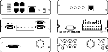
Communication
13-2 EATON Powerware®9390 UPS (100–160 kVA) Installation and Operation Manual S164201604 Rev B powerware.com
LAN and telephone drops for use with X-Slot connectivity cards must be provided by
facility planners or the customer.
For installation and setup of an X-Slot card, please contact Powerware (see page 1-6). Refer
to the manual supplied with the X-Slot card for user instructions.
Relay Interface Card
Modem Card
Modbus Card
ConnectUPS-X Web/SNMP Card
Powerware Hot Sync
CAN Bridge Card
Industrial Relay Card
Figure13-1.OptionalX-SlotCards
13.2 LanSafe Power Management Software
Each Powerware 9390 UPS ships with LanSafe Power Management Software. To begin
installing LanSafe software, see the instructions accompanying the Powerware Software
Suite CD.
LanSafe software uses an RS-232 serial link to communicate with theUPS.Thesoftware
provides up-to-date graphics of UPS power and system data and power flow, a complete
record of critical power events, and notification of important UPS or power information.
With custom views for monitoring status and metering information, various user groups
can select the most useful view for their specific needs.
13.3 Remote Notification
For connection and setup of a modem, or to enable Remote Notify and Call Home features
within the UPS, please contact Powerware (see page 1-6).
Remote Notification provides the UPS with the capability to use a standard off-the-shelf PC
modem as a telephone interface. The features provided by this option are:
쑺Call a remote terminal or pager based on programmable events and alarms
쑺Four separate, programmable notification groups (phone numbers)
쑺Automatic answering (user-configurable) for access to the Terminal mode of the UPS
쑺Remote and local ability to clear Call Out alarms and events
쑺Error detection and correction for misconfigured and disconnected modems.
Remote Notification provides the user with the option of receiving alarms and notices at a
remote location. Using the Terminal mode, the user calls the UPS to perform basic
monitoring. In the event of a UPS alarm or notice, the user is notified at the remote
location. The UPS calls through the modem to the user’s computer or pager and leaves a
message.

Communication
13-3
EATON Powerware®9390 UPS (100–160 kVA) Installation and Operation Manual S164201604 Rev B powerware.com
Remote Notification is an extension of the Terminal mode with the additional support
algorithms necessary to control an external modem. Connection to the UPS is made when
ausercallstheUPSonthephone.Theuserhasexactlythesamecapabilitiesasifusinga
terminal connected directly to an RS-232 port.
Remote Notification differs from the basic Terminal mode with the addition the following
functions:
쑺Call Answer
The Call Answer function allows the user to call into the UPS from a remote location
and enter Terminal mode.
쑺Call Out
The Call Out function allows the UPS to be configured to call either a remote computer
or numeric paging service over the phone line. Call Out allows the UPS to call a remote
computer and leave a one-line descriptive message of the alarm or notice condition.
Numeric paging support allows the UPS to call a paging service and send numeric
messages.
쑺Housekeeping
The Housekeeping function maintains the link between the UPS and modem.
13.4 Terminal Mode
NOTE The brackets ([ ]) in the following bullets indicate standard keyboard characters.
To use a key combination, hold down the Escape key and press the indicated letter key.
In Terminal mode, the user can request the following:
쑺[ESC] [V] displays the UPS control panel.
쑺[ESC] [H] displays the Event History.
쑺[ESC][N]displaystheNodeBitsSetup.
쑺[ESC] [L] displays any new event.
쑺[ESC] [B] displays the Battery Log.
13.4.1 Display UPS Control Panel
When this function is invoked, a facsimile of the UPS control panel is displayed on the
terminal screen. All controls are functional and can control the UPS remotely. The only
exception is the Load Off control which requires the operator to press and hold the local
control for two seconds to shut down the UPS.
To remotely control the UPS or view UPS information, use the escape key legend to
control the function normally controlled by the control panel softkeys. See Chapter 9,
“Using the Control Panel,” for instructions on navigating the control panel.

Communication
13-4 EATON Powerware®9390 UPS (100–160 kVA) Installation and Operation Manual S164201604 Rev B powerware.com
13.4.2 Event History Log
This key sequence prints the entire Event History Log of the UPS at the time the data is
requested. The printout begins with the oldest alarm entry in the queue and ends with the
most recent. Any alarms that occur while the Event History Log is printing are included in
chronological order.
The Event History Log lists up to 500 system events in chronological order with the most
recent event listed last. Figure 13-2 shows a sample Event History Log printout.
In this mode, system events are continually logged through the serial port to the device
connected to the port.
The printed log entries contain a time and date stamp and the alarm text message.
Terminal mode uses this format for printing alarm entries:
MM DD YYYY HH:MM:SS.hh KYWD MESSAGE <CR> <LF>
Where: Equals:
MM Month (2 digits)
DD Day (2 digits)
YYYY Year (4 digits)
HH Hour (2 digits)
MM Minute (2 digits)
SS Second (2 digits)
hh Hundredths of Second (3 digits)
KYWD Keyword (ALARM, NOTICE, COMMAND, or STATUS)
MESSAGE System Diagnostic Information
<CR> Carriage Return Character (ASCII 13)
<LF> Line Feed (ASCII 10)
An alarm message is prefixed by the word “CLEAR” whenever an alarm is entered into the
Event History Log with a cleared status.
If a port is operating in Terminal mode and is connected to a computer, you can press
[Esc] [H] to print the entire log with a firmware version header.
Communication
13-5
EATON Powerware®9390 UPS (100–160 kVA) Installation and Operation Manual S164201604 Rev B powerware.com
03/11/2004 14:13:03.000 STATUS: CSB Power Supply On
03/11/2004 14:13:03.043 NOTICE: Inverter Initializing
03/11/2004 14:13:05.721 STATUS: UPS Power Supply OK
03/11/2004 14:13:05.728 NOTICE: Input Under Voltage
03/11/2004 14:13:05.729 NOTICE: Output Under Voltage
03/11/2004 14:13:05.729 NOTICE: Bypass Under Voltage
03/11/2004 14:13:05.749 ALARM: Rectifier Under Voltage
03/11/2004 14:13:10.459 ALARM: Battery Under Voltage
03/11/2004 14:13:12.954 NOTICE: Battery Voltage Low
03/11/2004 14:13:13.165 NOTICE: Battery Not Present
03/11/2004 14:13:34.710 STATUS: PPU Shutdown
03/11/2004 14:13:57.773 NOTICE: Check Modem
03/11/2004 14:14:33.520 ALARM: Inverter Tripped
03/11/2004 14:14:33.520 ALARM: Check Inverter
03/11/2004 14:27:09.000 STATUS: CSB Power Supply On
03/11/2004 14:27:09.043 NOTICE: Inverter Initializing
03/11/2004 14:27:11.725 STATUS: UPS Power Supply OK
03/11/2004 14:27:11.733 NOTICE: Input Under Voltage
03/11/2004 14:27:11.733 NOTICE: Output Under Voltage
03/11/2004 14:27:11.733 NOTICE: Bypass Under Voltage
03/11/2004 14:27:11.754 ALARM: Rectifier Under Voltage
03/11/2004 14:27:16.464 ALARM: Battery Under Voltage
03/11/2004 14:27:18.954 NOTICE: Battery Voltage Low
03/11/2004 14:27:19.169 NOTICE: Battery Not Present
03/11/2004 14:27:40.714 STATUS: PPU Shutdown
03/11/2004 14:28:04.023 NOTICE: Check Modem
03/12/2004 14:15:09.000 STATUS: CSB Power Supply On
03/12/2004 14:15:09.043 NOTICE: Inverter Initializing
03/12/2004 14:15:11.725 STATUS: UPS Power Supply OK
03/12/2004 14:15:11.733 NOTICE: Input Under Voltage
03/12/2004 14:15:11.733 NOTICE: Output Under Voltage
03/12/2004 14:15:11.754 ALARM: Rectifier Under Voltage
03/12/2004 14:15:11.833 NOTICE: Maintenance Bypass On
03/12/2004 14:15:16.463 ALARM: Battery Under Voltage
03/12/2004 14:15:18.954 NOTICE: Battery Voltage Low
03/12/2004 14:15:19.169 NOTICE: Battery Not Present
03/12/2004 14:15:40.714 STATUS: PPU Shutdown
03/12/2004 14:16:04.023 NOTICE: Check Modem
03/12/2004 14:16:22.925 CMD: Bypass Mode Command
03/12/2004 14:16:23.443 STATUS: K5 (Backfeed) Closed
03/12/2004 14:16:23.586 STATUS: On Bypass
03/12/2004 14:16:24.860 NOTICE: Output Under Voltage OK
03/12/2004 14:17:20.900 NOTICE: Input Under Voltage OK
03/12/2004 14:17:23.606 ALARM: Rectifier Under Voltage OK
03/12/2004 14:17:25.557 ALARM: Battery Under Voltage OK
03/12/2004 14:19:01.899 CMD: PPU On Command
03/12/2004 14:19:04.089 STATUS: K1 (Input) Closed
Figure 13-2. Sample Event History Log
Communication
13-6 EATON Powerware®9390 UPS (100–160 kVA) Installation and Operation Manual S164201604 Rev B powerware.com
This page intentionally left blank.

14-1
EATON Powerware®9390 UPS (100–160 kVA) Installation and Operation Manual S164201604 Rev B powerware.com
Chapter 14 Maintaining the UPS System
The components inside the UPS cabinet are secured to a sturdy metal frame. All repairable
parts and assemblies are located for easy removal, with very little disassembly. This design
allows authorized service personnel to perform routine maintenance and servicing quickly.
You must schedule periodic performance checks of your UPS system to keep it running
properly. Regular routine checks of operation and system parameters enable your system
to function efficiently for many trouble-free years.
14.1 Important Safety Instructions
Remember that your UPS system is designed to supply power EVEN WHEN
DISCONNECTED FROM THE UTILITY POWER. The UPS module interiors are unsafe until
the DC power source is disconnected and the electrolytic capacitors are discharged. After
disconnecting the utility power and the DC power, authorized service personnel should
wait at least five minutes for capacitor bleedoff before attempting internal access to the
UPS module.
WARNING
쑺Servicing and maintenance should be performed by qualified service personnel only.
쑺LETHAL VOLTAGE PRESENT. This unit should not be operated with the cabinet doors open
or protective panels removed. Do not make any assumptions about the electrical state of
any cabinet in the UPS system.
Since each battery string is an energy source in itself, opening the battery circuit breaker
does not de-energize the voltage within the battery string. DO NOT ATTEMPT TO ACCESS
ANY INTERNAL AREA OF THE BATTERY STRING YOURSELF. VOLTAGES ARE ALWAYS
PRESENT IN THE BATTERY STRING. If you suspect that a battery string needs service, you
should contact your Eaton service representative.
If the string requires service, refer to the battery manufacturer’s operating manual for
instructions on battery maintenance or contact your Eaton service representative.
Observe these precautions when working on or around batteries:
쑺Remove watches, rings, or other metal objects.
쑺Use tools with insulated handles.
쑺Wear rubber gloves and boots.
쑺Do not lay tools or metal parts on top of batteries or battery cabinets.
쑺Disconnect the charging source prior to connecting or disconnecting terminals.

Maintaining the UPS System
14-2 EATON Powerware®9390 UPS (100–160 kVA) Installation and Operation Manual S164201604 Rev B powerware.com
쑺Determine if the battery is inadvertently grounded. If it is, remove the source of the
ground. Contact with any part of a grounded battery can result in electrical shock. The
likelihood of such shock is reduced if such grounds are removed during installation and
maintenance.
쑺When replacing batteries, use the same number of sealed, lead-acid batteries.
쑺Proper disposal of batteries is required. Refer to your local codes for disposal
requirements.
WARNING
쑺HAZARDOUS WASTE. Do not incinerate or dispose of batteries indiscriminately. Observe
local and national codes.
쑺Do not dispose of battery or batteries in a fire. The battery may explode.
쑺Do not open or mutilate the battery or batteries. Released electrolyte is harmful to the skin
and eyes, and may be toxic.
쑺A battery can cause electrical shock, burn from high short-circuit current, or fire. Observe
proper precautions.
ATTENTION!
쑺Une batterie peut prêsenter un risque de choc êlectrique, de brulure, ou d’incendie. Suivre
les précautions qui s’imposent.
쑺Pour le remplacement, utiliser le même nombre et modéle des batteries.
쑺L’élimination des batteries est règlementée. Consulter les codes locaux à cet effet.
14.2 Performing Preventive Maintenance
The UPS system requires very little preventive maintenance. However, the system should be
inspected periodically to verify that the units are operating normally and that the batteries
are in good condition.
14.2.1 DAILY Maintenance
Perform the following steps daily:
1. Check the area surrounding the UPS system. Ensure the area is not cluttered,
allowing free access to the unit.
2. Ensuretheairintakes(ventsonthefront doors) and exhaust opening (on top of
the UPS cabinet sections) are not blocked.
Maintaining the UPS System
14-3
EATON Powerware®9390 UPS (100–160 kVA) Installation and Operation Manual S164201604 Rev B powerware.com
3. Ensure the operating environment is within the parameters specified in
Chapter 15, “Product Specifications,” and Drawing 164201604-2 on page A-3.
4. Ensure the UPS is in Normal mode (Normal status indicator is illuminated). If an
alarm lamp is illuminated or the Normal status indicator is not illuminated, contact
your Eaton service representative.
14.2.2 MONTHLY Maintenance
Perform the following steps monthly:
1. Monitor system parameters as described in Chapter 9, “Using the Control Panel.”
2. Check the air filters (located behind the front doors) and replace as necessary. The
left filter size is 16″×30″×1″and the right filter size is 12″×30″×1″.Toremove
the filters:
a. Open the front door latch and swing the doors open.
b. Slide each filter up and remove from the cabinet.
c. Slide the new filters into the brackets until seated on the bottom brackets.
d. Close the doors and secure the latch.
3. Record the check results and any corrective actions in a suitable log.
14.2.3 ANNUAL Maintenance
Annual preventive maintenance should be performed only by authorized service personnel
familiar with maintenance and servicing of the UPS system. Contact your Eaton service
representative for more information about service offerings.
14.2.4 BATTERY Maintenance
Contact your Eaton service representative for battery maintenance. Battery replacement
and maintenance should be performed only by authorized service personnel.
14.3 Maintenance Training
A basic training course, available from Powerware, gives you a competent working
knowledge of the UPS system operation and teaches you how to perform first level
corrective maintenance. For more information about training and other services, contact
the Eaton Help Desk for Powerware products (see page 1-6).
Maintaining the UPS System
14-4 EATON Powerware®9390 UPS (100–160 kVA) Installation and Operation Manual S164201604 Rev B powerware.com
This page intentionally left blank.

15-1
EATON Powerware®9390 UPS (100–160 kVA) Installation and Operation Manual S164201604 Rev B powerware.com
Chapter 15 Product Specifications
15.1 Model Numbers
The UPS systems are housed in free-standing cabinets with safety shields behind the doors.
The UPS systems are available in 50/60 Hz with various output power ratings.
Models Powere Rating Frequency
Powerware 9390-120/100 100 kVA 50/60 Hz
Powerware 9390-120/120 120 kVA 50/60 Hz
Powerware 9390-160/100 100 kVA 50/60 Hz
Powerware 9390-160/120 120 kVA 50/60 Hz
Powerware 9390-160/160 160 kVA 50/60 Hz
The following sections detail the input, output, environmental, and battery specifications
for the UPS.
15.2SingleModuleSpecifications
15.2.1 UPS System Input
Operating Input Voltage
(Nominal +10/–15%)
208 Vac for operation from 177 Vac to 229 Vac
220 Vac for operation from 187 Vac to 242 Vac
480 Vac for operation from 408 Vac to 528 Vac
Operating Input
Frequency Range
¦5Hz
Operating Input Current See Appendix A, Table E through Table G.
Reduced for Generator
Adjustable
Input Current Harmonic
Content
5% THD at full load
Power Factor Minimum 0.99
Line Surges 6 kV OC, 3 kA SC per ANSI 62.41 and IEC 801-4
Battery Voltage 384 Vdc (208V/220V units only)
432 Vdc
480 Vdc

Product Specifications
15-2 EATON Powerware®9390 UPS (100–160 kVA) Installation and Operation Manual S164201604 Rev B powerware.com
15.2.2 UPS System Output
UPS Output Capacity 100% rated current
Output Voltage
Regulation
¦1% (10% to 100% load)
Output Voltage
Adjustment
(Nominal +/–3%)
208 Vac nominal, adjustable from 202 Vac to 214 Vac
220 Vac nominal, adjustable from 214 Vac to 226 Vac
480 Vac nominal, adjustable from 466 Vac to 494 Vac
Output Voltage Harmonic
Content
1.5% max THD (linear load)
5% max THD (nonlinear load)
Output Current See Appendix A, Table E through Table G.
Output Voltage Balance 3% for 100% maximum load imbalance (linear load)
Output Voltage Phase
Displacement
3° for 100% maximum load imbalance (linear load)
Output Transients 5% for 100% load step or removal
Frequency Regulation 0.01 Hz free running
Synchronous to Bypass Bypass within voltage limits of +5%, –8% of output setting;
bypass within 0.5 Hz
Frequency Slew Rate 1 Hz per second maximum
Overload Capability 110% for 10 minutes
125% for 30 seconds
150% for 10 seconds
15.2.3 Environmental
Operating Temperature 0 to 40°C (32–104°F) without derating. The recommended
operating temperature is 25°C (77°F).
Operating Altitude Maximum 1500m (5000 ft) at 40°C without derating
Storage Temperature –25 to +60°C, excluding batteries (prolonged storage above
40°C causes rapid battery self-discharge)
Relative Humidity
(operating and storage)
5% to 95% maximum noncondensing
Acoustical Noise 65 dB at a 1m distance, c weighted
EMI Suppression Meets FCC Regulation 47, Part 15, for class A devices
Electrostatic Discharge
(ESD) Immunity
Meets IEC 801-2 specifications. Withstands up to 25 kV pulse
without damage and with no disturbance or adverse effect to
the critical load.

Product Specifications
15-3
EATON Powerware®9390 UPS (100–160 kVA) Installation and Operation Manual S164201604 Rev B powerware.com
15.3 Multiple Module Parallel Specifications
15.3.1 UPM Input
Same as single module.
15.3.2 UPM Output
Same as single module.
15.3.3 Environmental
Same as single module.
15.3.4 Battery
Same as single module.
15.3.5 Module Tie Cabinet Input
Operating Input Voltage
(UPM Dependent)
208 Vac for operation from 177 Vac to 229 Vac
220 Vac for operation from 187 Vac to 242 Vac
480 Vac for operation from 408 Vac to 528 Vac
Operating Input Current See Appendix A, Table O through Table Q.
15.3.6 Module Tie Cabinet Output
Operating Output Voltage
(UPM Dependent)
208 Vac for operation from 177 Vac to 229 Vac
220 Vac for operation from 187 Vac to 242 Vac
480 Vac for operation from 408 Vac to 528 Vac
Operating Output Current See Appendix A, Table O through Table Q.
Product Specifications
15-4 EATON Powerware®9390 UPS (100–160 kVA) Installation and Operation Manual S164201604 Rev B powerware.com
This page intentionally left blank.

A-1
EATON Powerware®9390 UPS (100–160 kVA) Installation and Operation Manual S164201604 Rev B powerware.com
Appendix A 16- Installation Information
The information in this appendix is helpful during the planning and installation of
the UPS system. This appendix contains the following drawings:
쑺164201604-1 Typical Powerware 9390 UPS System
쑺164201604-2 Physical Features and Requirements
쑺164201604-3 UPS System Oneline Configurations
쑺164201604-4 UPS System Oneline Drawing
쑺164201604-5 Power Wiring Installation Notes
쑺164201604-6 Conduit and Wire Entry Locations
쑺164201604-7 UPS Power Terminal Locations
쑺164201604-8 Interface Wiring Installation Notes and Terminal Locations
쑺164201604-9 UPS Cabinet Dimensions
쑺164201604-10 Optional Remote Emergency Power-off
쑺164201604-11 Optional Remote Monitor Panel
쑺164201604-12 Optional Remote Relay Interface Module
쑺164201604-13 Optional Remote Supervisory Contact Module
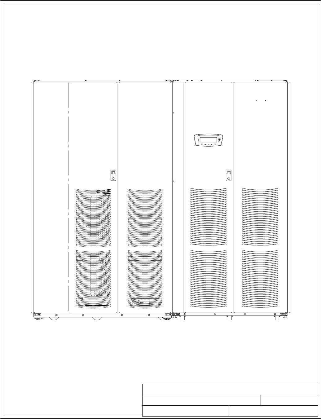
BATTERY CABINET UPS CABINET
164201604---1 1 of 1
TYPICAL POWERWARE 9390 UPS SYSTEM
091505A
DESCRIPTION:
DATE:
DRAWING NO: SHEET:
REVISION:
Installation Information
A-2 EATON Powerware®9390 UPS (100–160 kVA) Installation and Operation Manual S164201604 Rev B powerware.com
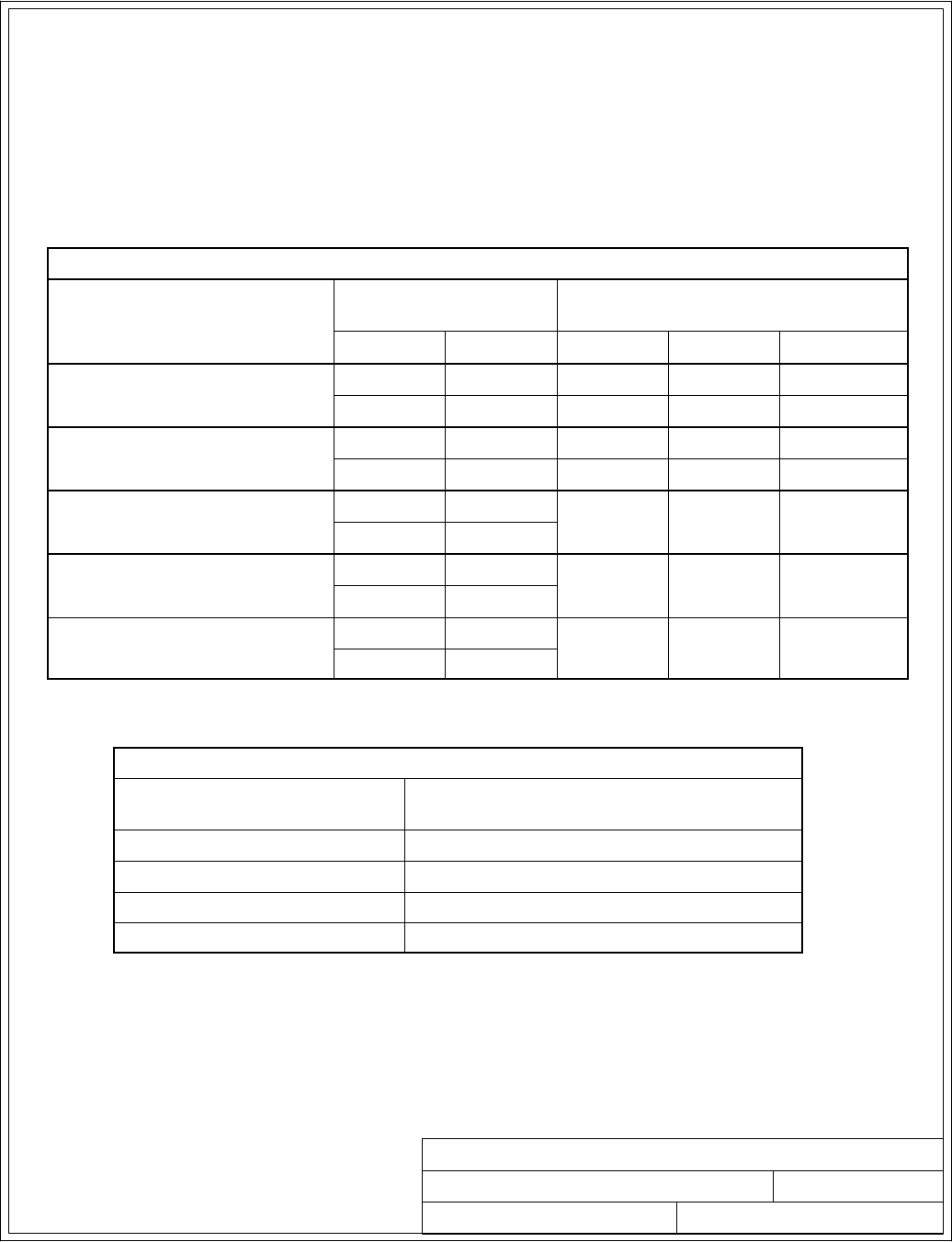
164201604---2 1 of 2
PHYSICAL FEATURES AND REQUIREMENTS
091505A
DESCRIPTION:
DATE:
DRAWING NO: SHEET:
REVISION:
Installation Information
A-3
EATON Powerware®9390 UPS (100–160 kVA) Installation and Operation Manual S164201604 Rev B powerware.com
1. The UPS equipment operating environment must meet the weight requirements shown in
Table A and the size requirements shown on Drawing 164201604---9.
2. The UPS cabinet is palleted separately for shipping.
3. Donottiltcabinetsmorethan10˚during handling.
4. Dimensions are in millimeters (inches).
5. Thecabinetcanbeinstalledinline-up-and-match or standalone configurations.
Table A. UPS Cabinet Weight
Model Voltage Weight
kg (lb)
Input Output Shipping Installed Point Loading
Powerware 9390---120/100 208V/220V 208V/220V 531 (1170) 504 (1110) 6 at 84 (185)
480V 480V 467 (1030) 440 (970) 6 at 73 (162)
Powerware 9390---120/120 208V/220V 208V/220V 531 (1170) 553 (1110) 6 at 84 (185)
480V 480V 467 (1030) 440 (970) 6 at 73 (162)
Powerware 9390---160/100 208V/220V 208V/220V 581 (1280) 553 (1220) 6 at 92 (204)
480V 480V
Powerware 9390---160/120 208V/220V 208V/220V 581 (1280) 553 (1220) 6 at 92 (204)
480V 480V
Powerware 9390---160/160 208V/220V 208V/220V 581 (1280) 553 (1220) 6 at 92 (204)
480V 480V
6. The clearances required around the UPS cabinet are shown in Table B.
Table B. UPS Cabinet Clearances
From Top of Cabinet Minimum clearance over the UPS cabinet is
457.2 mm (18 in.) for ventilation
From Front of Cabinet 914.4 mm (36 inches) working space
From Back of Cabinet None required
From Right Side of Cabinet None required
From Left Side of Cabinet None required
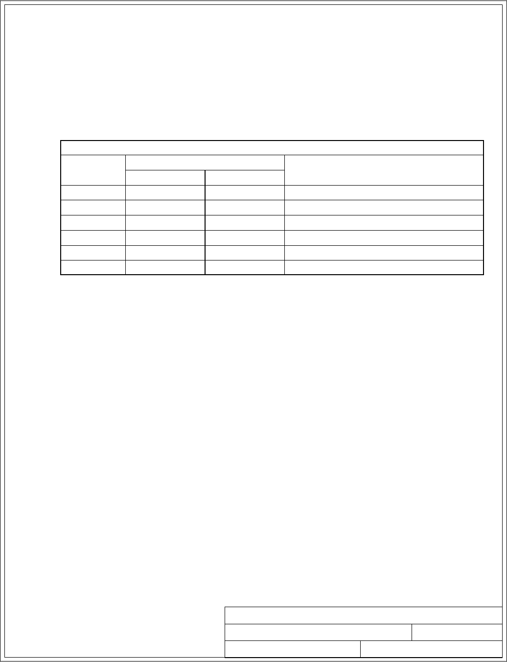
2of2
PHYSICAL FEATURES AND REQUIREMENTS
091505A
164201604---2
DESCRIPTION:
DATE:
DRAWING NO: SHEET:
REVISION:
Installation Information
A-4 EATON Powerware®9390 UPS (100–160 kVA) Installation and Operation Manual S164201604 Rev B powerware.com
7. The basic environmental requirements for operation of the UPS system are:
Ambient Temperature Range: 0 --- 4 0 ˚C (32---104˚F)
Recommended Operating Range: 20---25˚C (68---77˚F)
Maximum Relative Humidity: 95%, noncondensing
The UPS ventilation requirements are shown in Table C.
Table C. Air Conditioning or Ventilation Requirements During Full Load Operation
Ratings Voltage Heat Rejection
BTU/hr
¢
1000/hr (kg-cal/hr)
Input Output
100 kVA 208/220 208/220 29.6 (7.45)
100 kVA 480 480 27.4 (6.90)
120 kVA 208/220 208/220 35.5 (8.94)
120 kVA 480 480 32.8 (8.28)
160 kVA 208/220 208/220 47.3 (11.9)
160 kVA 480 480 43.8 (11.0)
Ventilation required for cooling air exhaust: approximately 9.44 liter/sec (2000 cfm).
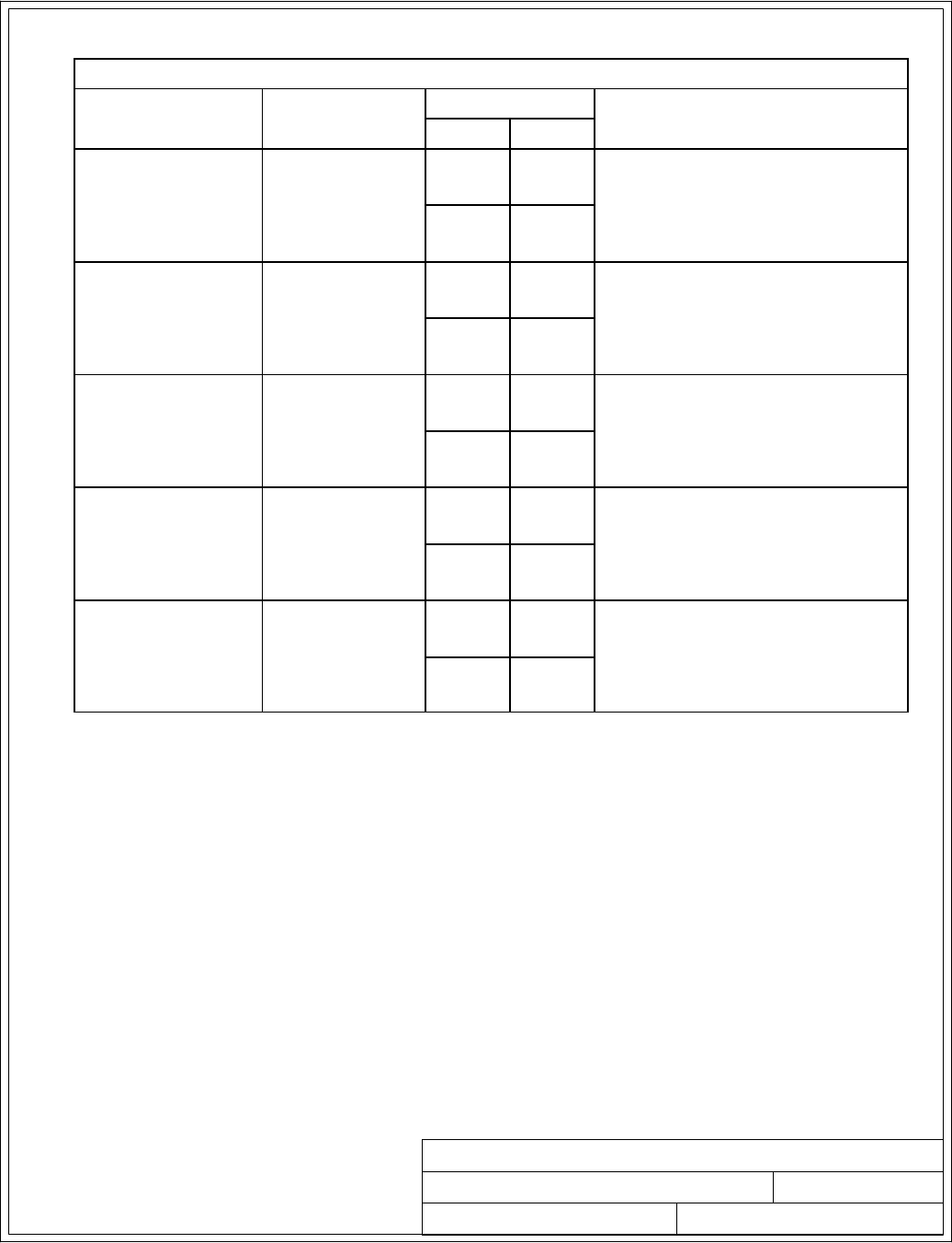
1of1
UPS SYSTEM ONELINE CONFIGURATIONS
091505A
164201604---3
DESCRIPTION:
DATE:
DRAWING NO: SHEET:
REVISION:
Installation Information
A-5
EATON Powerware®9390 UPS (100–160 kVA) Installation and Operation Manual S164201604 Rev B powerware.com
Table D. UPS System Oneline Configurations
Oneline Drawing
164201604---4
UPS
Model
Voltage System Type
Input Output
Sheet 1
9390---120/100
9390---120/120
9390---160/100
9390---160/120
9390---160/160
208/220 208/220
Single Module --- Reverse Transfer
Single-Feed or Dual-Feed
480 480
Sheet 2
9390---120/100
9390---120/120
9390---160/100
9390---160/120
9390---160/160
208/220 208/220 Single Module --- Reverse Transfer
Single-Feed with Typical
Maintenance Bypass Panel
480 480
Sheet 3
9390---120/100
9390---120/120
9390---160/100
9390---160/120
9390---160/160
208/220 208/220 Multiple Module --- Parallel
Single-Feed or Dual-Feed
1+1 and 2+0 Configurations
480 480
Sheet 4
9390---120/100
9390---120/120
9390---160/100
9390---160/120
9390---160/160
208/220 208/220 Multiple Module --- Parallel
Single-Feed or Dual-Feed
2+1 and 3+0 Configurations
480 480
Sheet 5
9390---120/100
9390---120/120
9390---160/100
9390---160/120
9390---160/160
208/220 208/220 Multiple Module --- Parallel
Single-Feed or Dual-Feed
3+1 and 4+0 Configurations
480 480
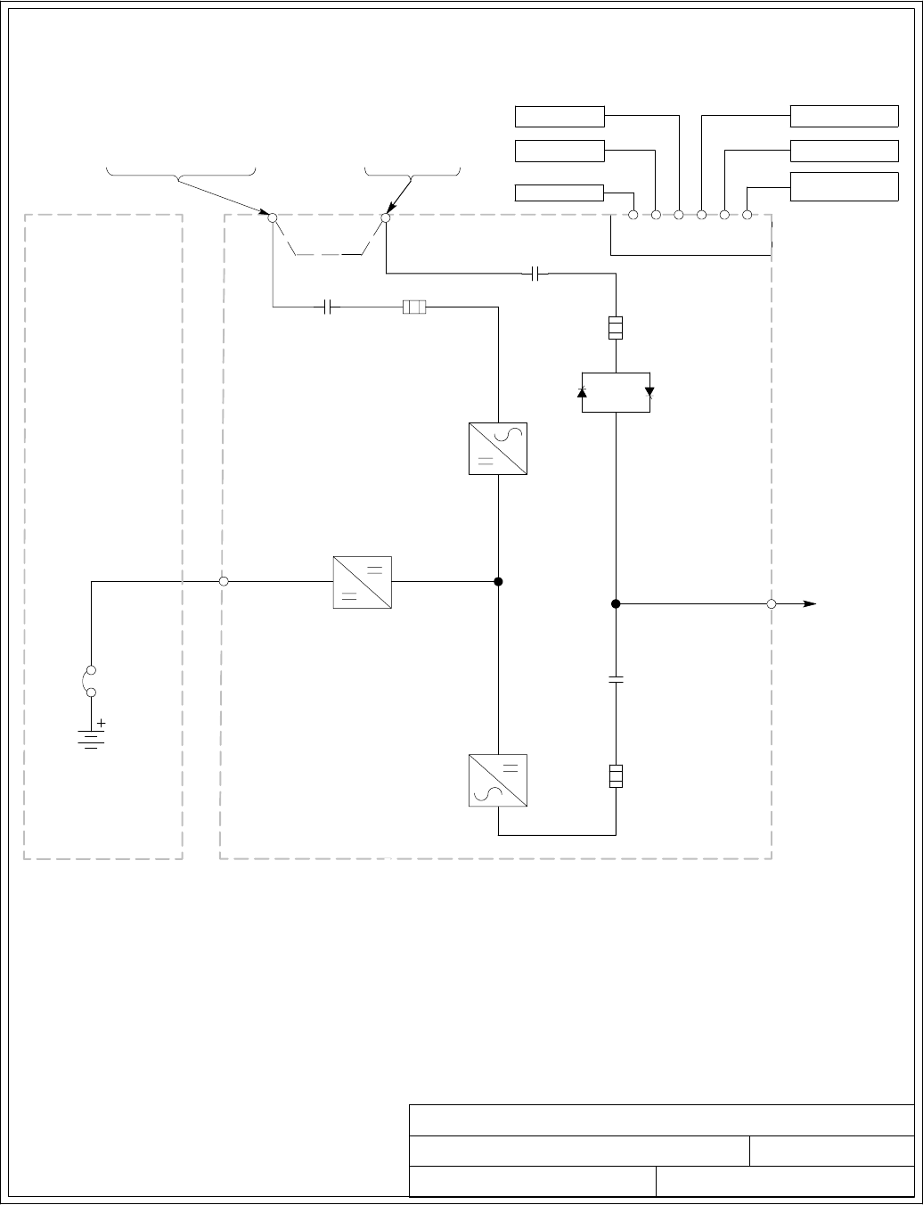
BATTERY
BREAKER
1of6
UPS SYSTEM ONELINE DRAWING
032406B
164201604---4
DESCRIPTION:
DATE:
DRAWING NO: SHEET:
REVISION:
UPS CABINET
INVERTER
RECTIFIER
STATIC
SWITCH
REMOTE EPO
BUILDING ALARMS
AC OUTPUT
TO
CRITICAL LOAD
AC INPUT TO
UPS RECTIFIER
3 W I R E A --- B --- C
AC INPUT
TO BYPASS
3 o r 4 W I R E A --- B --- C
ROTATION
ROTATION
(See Drawing 164201604---8)
POWERWARE 9390 120/100 AND
120/120 408V INPUT AND 480V OUTPUT
UPS SYSTEM
SINGLE-FEED OR DUAL-FEED
INPUT
CONTACTOR
(K1)
BATTERY
CONVERTER
BATTERY
CABINET
X-SLO T
INTERFACE
(Optional)
(DUAL FEED)
AC INPUT TO
UPS RECTIFIER AND BYPASS
(DUAL FEED)
(SINGLE-FEED )
FUSE
BACKFEED
CONTACTOR
(K5)
OUTPUT
CONTACTOR
(K3)
E4. E5
E9, E10,
E11, E12
FUSE
3 o r 4 W I R E A --- B --- C
ROTATION
ALARM RELAY
FUSE
INTERFACE
BOARD
BATTERY AUX
BATTERY UVR
AB
CD
E1, E2, E3 E6, E7, E8, E12
SEENOTE2
NOTE: 1. A minimum of two separate feeds with
upstream feeder breakers, or one feed
with two upstream feeder breakers, must
be provided: one for the UPS and one
for the IAC bypass input. DO NOT use
one feed or a single-feeder breaker to
supply both the UPS and the IAC.
2. Remove jumpers for dual-feed.
3. If the load requires a neutral, a bypass
neutral feeder must be supplied.
Installation Information
A-6 EATON Powerware®9390 UPS (100–160 kVA) Installation and Operation Manual S164201604 Rev B powerware.com
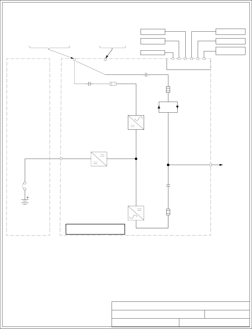
E1, E2, E3
BATTERY
BREAKER
UPS SYSTEM ONELINE DRAWING
032406D
164201604---4
DESCRIPTION:
DATE:
DRAWING NO: SHEET:
REVISION:
UPS CABINET
INVERTER
RECTIFIER
STATIC
SWITCH
REMOTE EPO
BUILDING ALARMS
AC OUTPUT
TO
CRITICAL LOAD
AC INPUT TO
UPS RECTIFIER
3 W I R E A --- B --- C
AC INPUT
TO BYPASS
3 o r 4 W I R E A --- B --- C
ROTATION
ROTATION
(See Drawing 164201604---8)
POWERWARE 9390 120/100, 120/120, 160/100 160/120
AND 160/160 208/220V INPUT AND OUTPUT AND
160/100, 160/120 AND 160/160 480V INPUT AND OUTPUT
UPS SYSTEM
SINGLE-FEED OR DUAL-FEED
INPUT
CONTACTOR
(K1)
BATTERY
CONVERTER
BATTERY
CABINET
X-SLO T
INTERFACE
(Optional)
(DUAL FEED)
AC INPUT TO
UPS RECTIFIER AND BYPASS
(DUAL FEED)
(SINGLE-FEED)
FUSE
BACKFEED
CONTACTOR
(K5)
OUTPUT
CONTACTOR
(K3)
E4. E5
E9, E10,
E11, E12
FUSE
3 o r 4 W I R E A --- B --- C
ROTATION
ALARM RELAY
FUSE
INTERFACE
BOARD
BATTERY AUX
BATTERY UVR
AB
CD
E6, E7, E8, E12
NOTE: 1. A minimum of two separate feeds with
upstream feeder breakers, or one feed
with two upstream feeder breakers, must
be provided: one for the UPS and one
for the IAC bypass input. DO NOT use
one feed or a single-feeder breaker to
supply both the UPS and the IAC.
2. Move bypass contactor wires to
bypass terminals for dual-feed.
3. If the load requires a neutral, a bypass
neutral feeder must be supplied.
2of6
SERIAL NUMBER SEVENTH
DIGITAT“A”
Installation Information
A-7
EATON Powerware®9390 UPS (100–160 kVA) Installation and Operation Manual S164201604 Rev B powerware.com
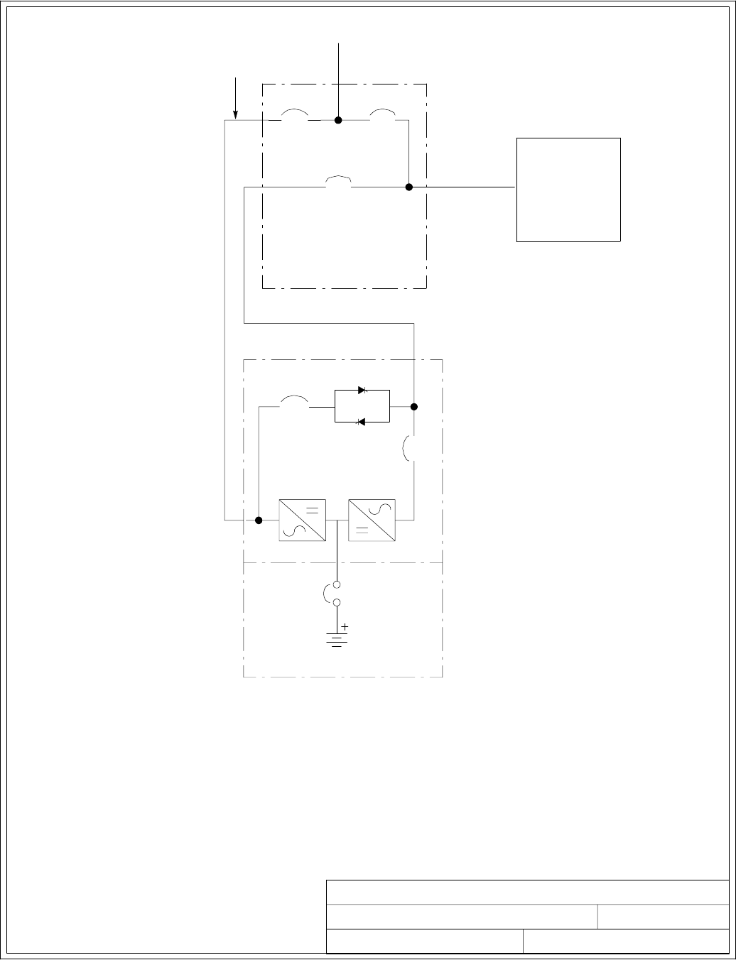
3of6
UPS SYSTEM ONELINE DRAWING
091505A
164201604---4
DESCRIPTION:
DATE:
DRAWING NO: SHEET:
REVISION:
MAINTENANCE
BYPASS PANEL
(PROVIDED BY OTHERS)
Output
from
UPS
MIB
To U P S
Input
MIB: MAINTENANCE ISOLATION BREAKER
MBP: MAINTENANCE BYPASS BREAKER
MBP
Backfeed
K5
K3
STATIC
SWITCH
AC INPUT
BATTERY
BREAKER
TYPICAL MAINTENANCE BYPASS PANEL POWER FLOW
BATTERY CABINET
UPS
CRITICAL LOAD
DISTRIBUTION
UNIT
If installing, as part of the UPS system, a maintenance bypass without a rectifier input
breaker, a minimum of two separate feeds with upstream feeder breakers, or one feed
with two upstream feeder breakers, must be provided: one for the UPS and one for the
maintenance bypass input. DO NOT use one feed or a single-feeder breaker to supply
both the UPS and the maintenance bypass.
NOTE:
Installation Information
A-8 EATON Powerware®9390 UPS (100–160 kVA) Installation and Operation Manual S164201604 Rev B powerware.com
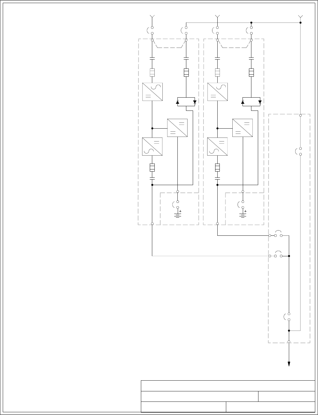
UPS SYSTEM ONELINE DRAWING
091505A
DESCRIPTION:
DATE:
DRAWING NO: SHEET:
REVISION:
OUTPUT TO
CRITICAL LOAD
BATTERY CABINET
BATTERY
BREAKER
E4. E5
E9
E10
E11
E12
FUSE
K5
STATIC
SWITCH
FUSE
K3
FUSE
BATTERY
CONVERTER
RECTIFIER
INVERTER
K1
UPM 1
E1
E2
E3
E6E
7E8
E12
AB
SEENOTE2
MODULE TIE
CABINET
(OPTIONAL)
DMOB 1
F
E
BATTERY CABINET
BATTERY
BREAKER
E4. E5
E9
E10
E11
E12
FUSE
K5
STATIC
SWITCH
FUSE
K3
FUSE
BATTERY
CONVERTER
RECTIFIER
INVERTER
K1
UPM 2
E1
E2
E3
E6E
7E8
E12
AB
SEENOTE2
D
MOB 2
MIS
MBP
TYPICALPARALLELSYSTEM
(1+1 AND 2+0 CONFIGURATIONS)
****
4of6
C
C
164201604---4
G
NOTE: 1. UPM and system bypass input feeds
must come from the same source.
2. Remove jumper for dual-feed.
3.SeeNote27onpageA---21for
neutral bonding instructions.
Installation Information
A-9
EATON Powerware®9390 UPS (100–160 kVA) Installation and Operation Manual S164201604 Rev B powerware.com
A-- AC Input to UPS Rectifier and Bypass (single-feed) and UPS Rectifier (dual-feed)
B-- AC Input to UPS Bypass (dual-feed)
C-- DC Input from Battery
D-- UPM AC Output to Parallel Tie Point
E-- AC Input Source
F-- System Bypass Input
G-- Output to Critical Load
*-- Overcurrent Protection Provided by Others
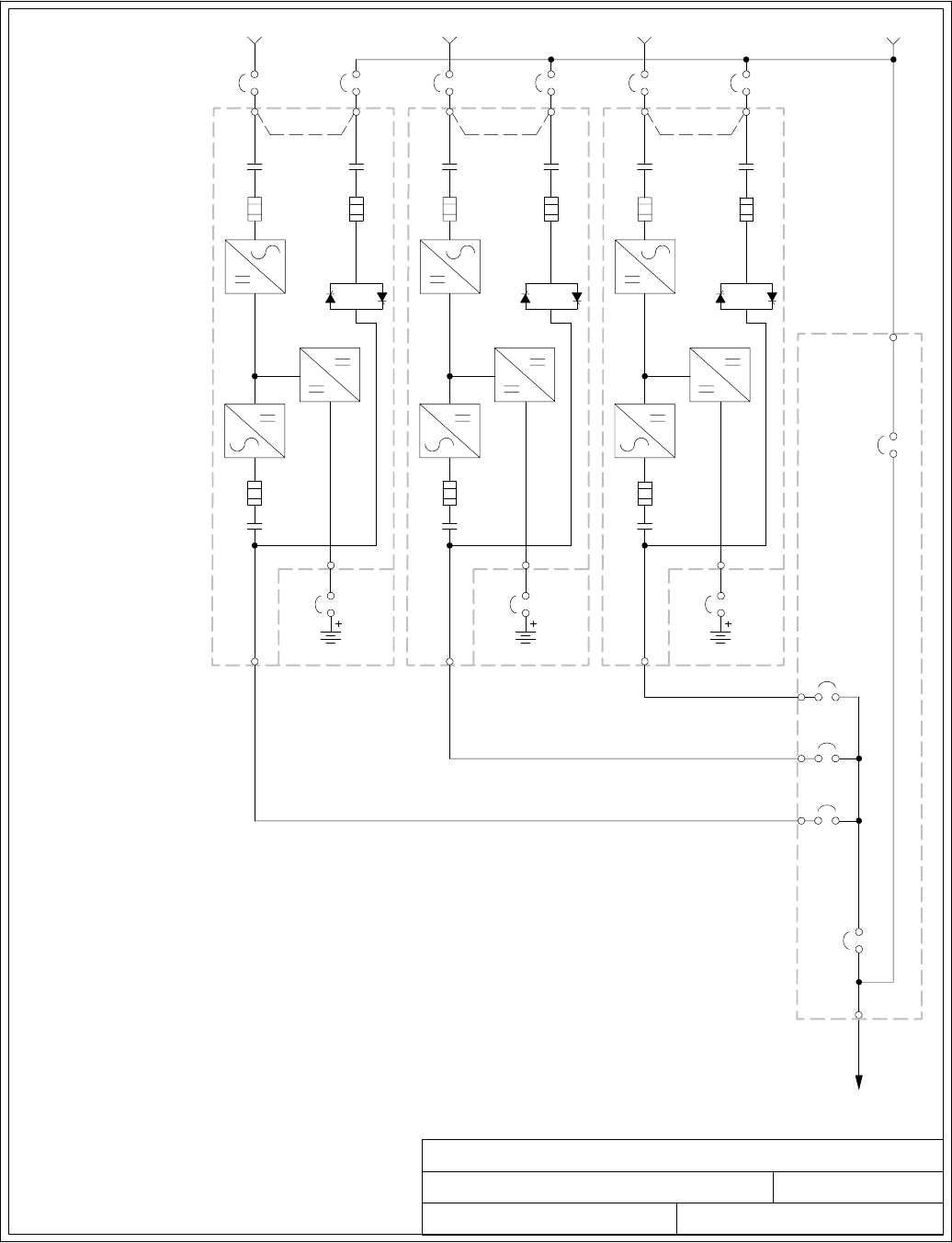
UPS SYSTEM ONELINE DRAWING
091505A
TYPICALPARALLELSYSTEM
(2+1 AND 3+0 CONFIGURATIONS)
5of6
164201604---4
NOTE: 1. UPM and system bypass input feeds
must come from the same source.
2. Remove jumper for dual-feed.
3.SeeNote27onpageA---21for
neutral bonding instructions.
DESCRIPTION:
DATE:
DRAWING NO: SHEET:
REVISION:
OUTPUT TO
CRITICAL LOAD
BATTERY CABINET
BATTERY
BREAKER
E4. E5
E9
E10
E11
E12
FUSE
K5
STATIC
SWITCH
FUSE
K3
FUSE
BATTERY
CONVERTER
RECTIFIER
INVERTER
K1
UPM 1
E1
E2
E3
E6E
7E8
E12
AB
SEENOTE2
DMOB 1
F
E
BATTERY CABINET
BATTERY
BREAKER
E4. E5
E9
E10
E11
E12
FUSE
K5
STATIC
SWITCH
FUSE
K3
FUSE
BATTERY
CONVERTER
RECTIFIER
INVERTER
K1
UPM 2
E1
E2
E3
E6E
7E8
E12
AB
SEENOTE2
D
BATTERY CABINET
BATTERY
BREAKER
E4. E5
E9
E10
E11
E12
FUSE
K5
STATIC
SWITCH
FUSE
K3
FUSE
BATTERY
CONVERTER
RECTIFIER
INVERTER
K1
UPM 3
E1
E2
E3
E6E
7E8
E12
A
B
SEENOTE2
D
MOB 3
MOB 2
MIS
MBP
** ****
CC
C
G
MODULE TIE
CABINET
(OPTIONAL)
Installation Information
A-10 EATON Powerware®9390 UPS (100–160 kVA) Installation and Operation Manual S164201604 Rev B powerware.com
A-- AC Input to UPS Rectifier and Bypass (single-feed) and UPS Rectifier (dual-feed)
B-- AC Input to UPS Bypass (dual-feed)
C-- DC Input from Battery
D-- UPM AC Output to Parallel Tie Point
E-- AC Input Source
F-- System Bypass Input
G-- Output to Critical Load
*-- Overcurrent Protection Provided by Others
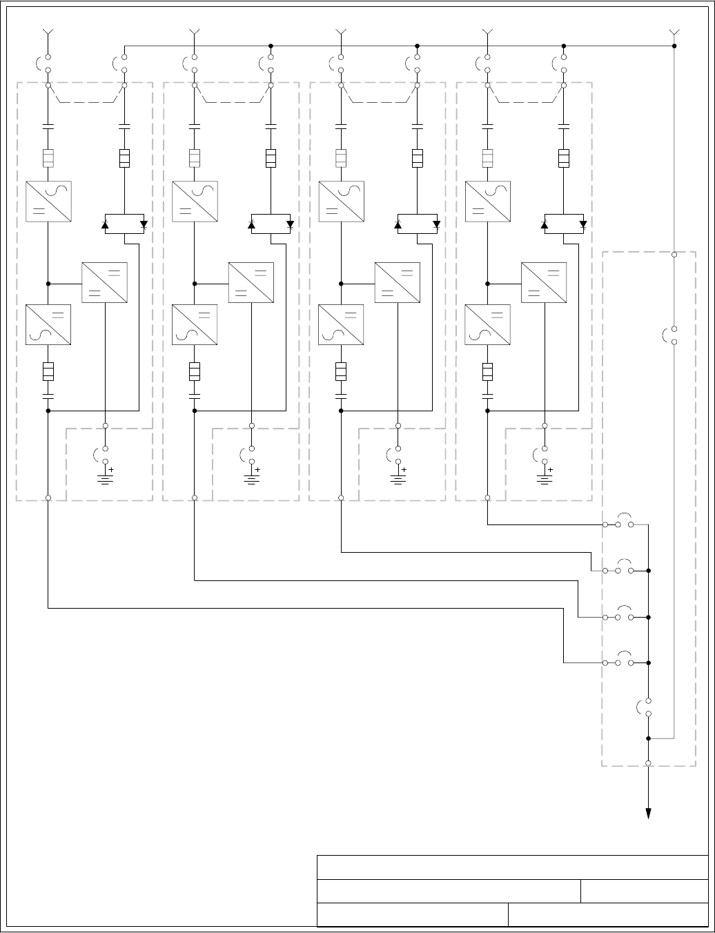
UPS SYSTEM ONELINE DRAWING
091505A
TYPICALPARALLELSYSTEM
(3+1 AND 4+0 CONFIGURATIONS)
6of6
164201604---4
NOTE: 1. UPM and system bypass input feeds
must come from the same source.
2. Remove jumper for dual-feed.
3.SeeNote27onpageA---21for
neutral bonding instructions.
DESCRIPTION:
DATE:
DRAWING NO: SHEET:
REVISION:
OUTPUT TO
CRITICAL LOAD
BATTERY CABINET
BATTERY
BREAKER
E4. E5
E9
E10
E11
E12
FUSE
K5
STATIC
SWITCH
FUSE
K3
FUSE
BATTERY
CONVERTER
RECTIFIER
INVERTER
K1
UPM 1
E1
E2
E3
E6E
7E8
E12
AB
SEENOTE2
DMOB 1
F
E
BATTERY CABINET
BATTERY
BREAKER
E4. E5
E9
E10
E11
E12
FUSE
K5
STATIC
SWITCH
FUSE
K3
FUSE
BATTERY
CONVERTER
RECTIFIER
INVERTER
K1
UPM 2
E1
E2
E3
E6E
7E8
E12
AB
SEENOTE2
D
BATTERY CABINET
BATTERY
BREAKER
E4. E5
E9
E10
E11
E12
FUSE
K5
STATIC
SWITCH
FUSE
K3
FUSE
BATTERY
CONVERTER
RECTIFIER
INVERTER
K1
UPM 4
E1
E2
E3
E6E
7E8
E12
A
B
SEENOTE2
D
BATTERY CABINET
BATTERY
BREAKER
E4. E5
E9
E10
E11
E12
FUSE
K5
STATIC
SWITCH
FUSE
K3
FUSE
BATTERY
CONVERTER
RECTIFIER
INVERTER
K1
UPM 3
E1
E2
E3
E6E
7E8
E12
A
B
SEENOTE2
D
MOB 3
MOB 4
MOB 2
MIS
MBP
**** ****
CC CC
G
MODULE TIE
CABINET
(OPTIONAL)
Installation Information
A-11
EATON Powerware®9390 UPS (100–160 kVA) Installation and Operation Manual S164201604 Rev B powerware.com
A-- AC Input to UPS Rectifier and Bypass (single-feed) and UPS Rectifier (dual-feed)
B-- AC Input to UPS Bypass (dual-feed)
C-- DC Input from Battery
D-- UPM AC Output to Parallel Tie Point
E-- AC Input Source
F-- System Bypass Input
G-- Output to Critical Load
*-- Overcurrent Protection Provided by Others

1of15
POWER WIRING INSTALLATION NOTES
032406B
164201604---5
DESCRIPTION:
DATE:
DRAWING NO: SHEET:
REVISION:
Installation Information
A-12 EATON Powerware®9390 UPS (100–160 kVA) Installation and Operation Manual S164201604 Rev B powerware.com
Table E. INPUT/OUTPUT Ratings & External Wiring Requirements for the Powerware
9390---120/100 and 9390---160/100
Units Rating 50/60 Hz
BasicUnitRatingat0.9laggingpFload kVA
kW
100
90
100
90
Input and Bypass Input
Output
VOLTS
VOLTS
208/220
208/220
480
480
AC Input to UPS Rectifier (0.98 min. pF)
Full Load Current plus Battery Recharge Current
(3) Phases, (1) Ground
A
Amps 300 130
Minimum Conductor Size
Number per Phase
AWG or kcmil
(each)
3/0
(2)
4/0
(1)
AC Input to UPS Bypass
Full Load Current
(3) Phases, (1) Neutral---if required, (1) Ground B
Amps 278/262 120
Minimum Conductor Size
Number per Phase
AWG or kcmil
(each)
3/0
(2)
4/0
(1)
DC Input from Battery to UPS
(1) Positive, (1) Negative C
Vdc
Amps@ (2.0V/cell)
384---480
252
432---480
252
Minimum Conductor Size
Number per Pole
AWG or kcmil
(each)
2/0
(2)
2/0
(2)
AC Output to Critical Load
Full Load Current
(3) Phases, (1) Neutral---if required, (1) Ground D
Amps 278/262 120
Minimum Conductor Size
Number per Phase
AWG or kcmil
(each)
3/0
(2)
4/0
(1)
Neutral Bonding Jumper
Minimum Conductor Size
Number (See Note 7) --- AWG or kcmil
(each)
1/0
(1)
2
(1)
NOTE: Callout letters A,B,C,andDmap to Drawing 164201604 ---4, sheets 1 of 6,
2of6,4of6,5of6,and6of6.
Read and understand the following notes while planning and performing the installation:
1. Refer to national and local electrical codes for acceptable external wiring practices.
2. Material and labor for external wiring requirements are to be provided by designated
personnel.
3. For external wiring, use 90°C copper wire. See the appropriate information in Table E
through Table G. Wire sizes are based on using the specified breakers.
4. Wire ampacities are chosen from Table 310---16 of the NEC. Wire is 90°C specification.
5. If installing, as part of the UPS system, a maintenance bypass without a rectifier input
breaker, a minimum of two separate feeds with upstream feeder breakers, or one feed with
two upstream feeder breakers, must be provided: one for the UPS and one for the
maintenance bypass input. DO NOT use one feed or a single-feeder breaker to supply
both the UPS and the maintenance bypass.
POWER WIRING INSTALLATION NOTES
032406B
164201604---5 2 of 15
DESCRIPTION:
DATE:
DRAWING NO: SHEET:
REVISION:
Installation Information
A-13
EATON Powerware®9390 UPS (100–160 kVA) Installation and Operation Manual S164201604 Rev B powerware.com
Table F. INPUT/OUTPUT Ratings & External Wiring Requirements for the Powerware
9390---120/120 and 9390---160/120
Units Rating 50/60 Hz
BasicUnitRatingat0.9laggingpFload kVA
kW
120
108
120
108
Input and Bypass Input
Output
VOLTS
VOLTS
208/220
208/220
480
480
AC Input to UPS Rectifier (0.98 min. pF)
Full Load Current plus Battery Recharge Current
(3) Phases, (1) Ground
A
Amps 360 160
Minimum Conductor Size
Number per Phase
AWG or kcmil
(each)
4/0
(2)
4/0
(1)
AC Input to UPS Bypass
Full Load Current
(3) Phases, (1) Neutral---if required, (1) Ground B
Amps 333/315 144
Minimum Conductor Size
Number per Phase
AWG or kcmil
(each)
4/0
(2)
4/0
(1)
DC Input from Battery to UPS
(1) Positive, (1) Negative C
Vdc
Amps@ (2.0V/cell)
384---480
302
432---480
302
Minimum Conductor Size
Number per Pole
AWG or kcmil
(each)
3/0
(2)
3/0
(2)
AC Output to Critical Load
Full Load Current
(3) Phases, (1) Neutral---if required, (1) Ground D
Amps 333/315 144
Minimum Conductor Size
Number per Phase
AWG or kcmil
(each)
4/0
(2)
4/0
(1)
Neutral Bonding Jumper
Minimum Conductor Size
Number (See Note 7) --- AWG or kcmil
(each)
1/0
(1)
2
(1)
NOTE: Callout letters A,B,C,andDmap to Drawing 164201604 ---4, sheets 1 of 6,
2of6,4of6,5of6,and6of6.
6. The bypass feed into this equipment uses three or four wires. The rectifier feed into this
equipment uses three wires. The phases must be symmetrical about ground (from a Wye
source) for proper equipment operation.
7. If the load requires a neutral, a bypass source neutral must be provided. If the load does
not require a neutral and there is no neutral conductor connected at the bypass input, a
neutral to ground bonding jumper must be installed. DO NOT install both a source neutral
and a bonding jumper. See Table E through Table G for neutral bonding jumper wire sizes.
Bonding jumper must be copper wire.
CAUTION
HIGH IMPEDANCE GROUND SOURCES - If the source of supply is a high impedance ground (IT)
type, the input neutral conductor must be connected from the source of supply. If there is no
output neutral connected to the UPS, the neutral-forming tranformer kit (PN 103005400) may
be used instead of pulling a neutral from the source. If the load requires a neutral then an
input neutral conductor must be pulled into the UPS. In no circumstances shall a neutral to
ground bonding jumper be installed in the UPS.
POWER WIRING INSTALLATION NOTES
032406B
164201604---5 3of15
DESCRIPTION:
DATE:
DRAWING NO: SHEET:
REVISION:
Installation Information
A-14 EATON Powerware®9390 UPS (100–160 kVA) Installation and Operation Manual S164201604 Rev B powerware.com
Table G. INPUT/OUTPUT Ratings & External Wiring Requirements for the Powerware
9390---160/160
Units Rating 50/60 Hz
BasicUnitRatingat0.9laggingpFload kVA
kW
160
144
160
144
Input and Bypass Input
Output
VOLTS
VOLTS
208/220
208/220
480
480
AC Input to UPS Rectifier (0.98 min. pF)
Full Load Current plus Battery Recharge Current
(3) Phases, (1) Ground
A
Amps 480 210
Minimum Conductor Size
Number per Phase
AWG or kcmil
(each)
400
(2)
1/0
(2)
AC Input to UPS Bypass
Full Load Current
(3) Phases, (1) Neutral---if required, (1) Ground B
Amps 444/420 192
Minimum Conductor Size
Number per Phase
AWG or kcmil
(each)
400
(2)
1/0
(2)
DC Input from Battery to UPS
(1) Positive, (1) Negative C
Vdc
Amps@ (2.0V/cell)
384---480
403
432---480
403
Minimum Conductor Size
Number per Pole
AWG or kcmil
(each)
250
(2)
250
(2)
AC Output to Critical Load
Full Load Current
(3) Phases, (1) Neutral---if required, (1) Ground D
Amps 444/420 192
Minimum Conductor Size
Number per Phase
AWG or kcmil
(each)
400
(2)
1/0
(2)
Neutral Bonding Jumper
Minimum Conductor Size
Number (See Note 7) --- AWG or kcmil
(each)
1/0
(2)
2
(2)
NOTE: Callout letters A,B,C,andDmap to Drawing 164201604 ---4, sheets 1 of 6,
2of6,4of6,5of6,and6of6.
CAUTION
DELTA SOURCES (TN-S) - The Powerware 9390 UPS system can be operated only from a delta
supply source that is fully floating and if the neutral-forming transformer kit (PN 103005400) is
installed in the UPS. The UPS cannot be operated from a mid-point or end-point grounded
delta supply source. With this type of supply source, there is no capability to provide an output
neutral. In no circumstances shall a neutral to ground bonding jumper be installed in the UPS.
8. The UPS cabinet is shipped with a debris shield covering the ventilation grill on top of the
unit. Do not remove the debris shield until installation is complete. However, remove the
shield before operating the UPS. Once the debris shield is removed, do not place objects
on the ventilation grill.
9. Refer to Section Iof this manual for installation instructions.

POWER WIRING INSTALLATION NOTES
032406B
164201604---5
NOTE: Customer ground can be run in any conduit listed in Table J.
4of15
DESCRIPTION:
DATE:
DRAWING NO: SHEET:
REVISION:
Installation Information
A-15
EATON Powerware®9390 UPS (100–160 kVA) Installation and Operation Manual S164201604 Rev B powerware.com
10. Terminals are UL and CSA rated at 90˚C. Refer to Table H and Table I for power cable
terminations, and Table J for conduit requirements. Drawing 164201604---7 shows the
location of the power cable terminals inside the UPS cabinet.
Table H. UPS Cabinet Power Cable Terminations for the Powerware 9390---120/100 and
9390---120/120 (480V Input and 480V Output)
Terminal Function Termina l Function Size of Pressure
Termination
Tightening
Torqu e
Nm (lb in)
Type
Screw
AC Input to UPS Rectifier
and Bypass
(Single Input)
E1 Phase A 2 --- # 6 --- 2 5 0 k c m i l 42.4 (375) 5/16 in. Hex
E2 Phase B 2 --- # 6 --- 2 5 0 k c m i l 42.4 (375) 5/16 in. Hex
E3 Phase C 2 --- # 6 --- 2 5 0 k c m i l 42.4 (375) 5/16 in. Hex
AC Input to UPS Rectifier
(Dual Input)
E1 Phase A 2 --- # 6 --- 2 5 0 k c m i l 42.4 (375) 5/16 in. Hex
E2 Phase B 2 --- # 6 --- 2 5 0 k c m i l 42.4 (375) 5/16 in. Hex
E3 Phase C 2 --- # 6 --- 2 5 0 k c m i l 42.4 (375) 5/16 in. Hex
AC Input To Bypass
(Dual Input)
E6 Phase A 2 --- # 6 --- 2 5 0 k c m i l 42.4 (375) 5/16 in. Hex
E7 Phase B 2 --- # 6 --- 2 5 0 k c m i l 42.4 (375) 5/16 in. Hex
E8 Phase C 2 --- # 6 --- 2 5 0 k c m i l 42.4 (375) 5/16 in. Hex
Single-Feed To Dual-Feed
Remove Jumpers between
Rectifier Input Terminals
and Bypass Input
Terminals
Rectifier Phase A N/A 12.5 (110) M8 Hex Bolt
Bypass Phase A N/A 22.6 (200) M10 Hex Bolt
Rectifier Phase B N/A 12.5 (110) M8 Hex Bolt
Bypass Phase B N/A 22.6 (200) M10 Hex Bolt
Rectifier Phase C N/A 12.5 (110) M8 Hex Bolt
Bypass Phase C N/A 22.6 (200) M10 Hex Bolt
AC Output to
Critical Load
E9 Phase A 2 --- # 6 --- 2 5 0 k c m i l 42.4 (375) 5/16 in. Hex
E10 Phase B 2 --- # 6 --- 2 5 0 k c m i l 42.4 (375) 5/16 in. Hex
E11 Phase C 2 --- # 6 --- 2 5 0 k c m i l 42.4 (375) 5/16 in. Hex
DC Input from
Battery to UPS
E4 Positive 2 --- # 2 --- 6 0 0 k c m i l 56.5 (500) 1/2 in. Hex
E5 Negative 2 --- # 2 --- 6 0 0 k c m i l 56.5 (500) 1/2 in. Hex
Input and Output Neutral E12 Neutral 8 --- # 6 --- 2 5 0 k c m i l 42.4 (375) 5/16 in. Hex
Customer Ground Ground Ground 8 --- # 1 4 --- 1 / 0 5.6 (50) Slotted

POWER WIRING INSTALLATION NOTES
091505A
164201604---5
NOTE: Customer ground can be run in any conduit listed in Table J.
5of15
DESCRIPTION:
DATE:
DRAWING NO: SHEET:
REVISION:
Installation Information
A-16 EATON Powerware®9390 UPS (100–160 kVA) Installation and Operation Manual S164201604 Rev B powerware.com
Table I. UPS Cabinet Power Cable Terminations for the Powerware 9390---120/100,
9390---120/120, 9390---160/100, 9390---160/120, and 9390---160/160 (208V/220V Input and
208V/220V Output), and the Powerware 9390---160/100, 9390---160/120, and 9390---160/160
(480V Input and 480V Output)
Terminal Function Termina l Function Size of Pressure
Termination
Tightening
Torqu e
Nm (lb in)
Type
Screw
AC Input to UPS Rectifier
and Bypass
(Single Input)
E1 Phase A 2 --- # 2 --- 6 0 0 k c m i l 56.5 (500) 1/2 in. Hex
E2 Phase B 2 --- # 2 --- 6 0 0 k c m i l l 56.5 (500) 1/2 in. Hex
E3 Phase C 2 --- # 2 --- 6 0 0 k c m i l 56.5 (500) 1/2 in. Hex
AC Input to UPS Rectifier
(Dual Input)
E1 Phase A 2 --- # 2 --- 6 0 0 k c m i l 56.5 (500) 1/2 in. Hex
E2 Phase B 2 --- # 2 --- 6 0 0 k c m i l 56.5 (500) 1/2 in. Hex
E3 Phase C 2 --- # 2 --- 6 0 0 k c m i l l 56.5 (500) 1/2 in. Hex
AC Input To Bypass
(Dual Input)
E6 Phase A 2 --- # 2 --- 6 0 0 k c m i l 56.5 (500) 1/2 in. Hex
E7 Phase B 2 --- # 2 --- 6 0 0 k c m i l 56.5 (500) 1/2 in. Hex
E8 Phase C 2 --- # 2 --- 6 0 0 k c m i l 56.5 (500) 1/2 in. Hex
Single-Feed to Dual-Feed
Transfer Wires from
Rectifier Input Terminals
to Bypass Input Terminals
Rectifier Phase A N/A 12.5 (110) M8 Hex Bolt
Bypass Phase A N/A 12.5 (110) M8 Hex Bolt
Rectifier Phase B N/A 12.5 (110) M8 Hex Bolt
Bypass Phase B N/A 12.5 (110) M8 Hex Bolt
Rectifier Phase C N/A 12.5 (110) M8 Hex Bolt
Bypass Phase C N/A 12.5 (110) M8 Hex Bolt
AC Output to
Critical Load
E9 Phase A 2 --- # 2 --- 6 0 0 k c m i l 56.5 (500) 1/2 in. Hex
E10 Phase B 2 --- # 2 --- 6 0 0 k c m i l 56.5 (500) 1/2 in. Hex
E11 Phase C 2 --- # 2 --- 6 0 0 k c m i l l 56.5 (500) 1/2 in. Hex
DC Input from
Battery to UPS
E4 Positive 2 --- # 2 --- 6 0 0 k c m i l 56.5 (500) 1/2 in. Hex
E5 Negative 2 --- # 2 --- 6 0 0 k c m i l 56.5 (500) 1/2 in. Hex
Input and Output Neutral E12 Neutral 8 --- # 2 --- 6 0 0 k c m i l 56.5 (500) 1/2 in. Hex
Customer Ground Ground Ground 8 --- # 1 4 --- 1 / 0 5.6 (50) Slotted

POWER WIRING INSTALLATION NOTES
091505A
164201604---5 6of15
DESCRIPTION:
DATE:
DRAWING NO: SHEET:
REVISION:
Installation Information
A-17
EATON Powerware®9390 UPS (100–160 kVA) Installation and Operation Manual S164201604 Rev B powerware.com
11. PerNECarticle300-20(a),allthree-phaseconductorsmustberuninthesameconduit.
Neutral and ground must be run in the same conduit as the phase conductors.
12. Conduit is sized to accommodate one neutral conductor the same size as the phase
conductor and one #8 AWG ground conductor. If two neutral conductors or an oversized
neutral conductor are to be installed, check the size of the conduit needed to
accommodate the extra wire or size and use that conduit size in place of the conduit size
listed in Table J. All Powerware 9390 products can accommodate a double size neutral.
13. Conduit sizes were chosen from NEC Table C1, type letters RHH, RHW, RHW-2, TW, THW,
THHW, THW-2.
Table J. Power Cable Conduit Requirements
UPS Model Voltage Te r m inal
Number of
Wires in
Conduit
Minimum Conduit
TradeSize(inches)
Number of
Conduits
Powerware
9390---120/100
and
9390---160/100
208/220
AC
AC Input to UPS
(A,B,C,Gnd) 42-1/2 2
AC Input to Bypass
(A,B,C,Neut,Gnd) 52-1/2 2
Output
(A,B,C,Neut,Gnd) 52-1/2 2
DC
Battery
(Positive), (Negative), Gnd 5 2 1
Powerware
9390---120/100
and
9390---160/100
480
AC
AC Input to UPS
(A,B,C,Gnd) 42-1/2 1
AC Input to Bypass
(A,B,C,Neut,Gnd) 52-1/2 1
Output
(A,B,C,Neut,Gnd) 52-1/2 1
DC
Battery
(Positive), (Negative), Gnd 5 2 1
Powerware
9390---120/120
and
9390---160/120
208/220
AC
AC Input to UPS
(A,B,C,Gnd) 42-1/2 2
AC Input to Bypass
(A,B,C,Neut,Gnd) 52-1/2 2
Output
(A,B,C,Neut,Gnd) 52-1/2 2
DC
Battery
(Positive), (Negative), Gnd 5 2 1
Powerware
9390---120/120
and
9390---160/120
480
AC
AC Input to UPS
(A,B,C,Gnd) 41-1/2 2
AC Input to Bypass
(A,B,C,Neut,Gnd) 51-1/2 2
Output
(A,B,C,Neut,Gnd) 51-1/2 2
DC
Battery
(Positive), (Negative), Gnd 5 2 1

POWER WIRING INSTALLATION NOTES
A
164201604---5
091505
7of15
DESCRIPTION:
DATE:
DRAWING NO: SHEET:
REVISION:
Installation Information
A-18 EATON Powerware®9390 UPS (100–160 kVA) Installation and Operation Manual S164201604 Rev B powerware.com
Table J. Power Cable Conduit Requirements (Cont’d)
UPS Model Voltage Te r m inal
Number of
Wires in
Conduit
Minimum Conduit
TradeSize(inches)
Number of
Conduits
Powerware
9390---160/160
208/220
AC
AC Input to UPS
(A,B,C,Gnd) 43-1/2 2
AC Input to Bypass
(A,B,C,Neut,Gnd) 53-1/2 2
Output
(A,B,C,Neut,Gnd) 53-1/2 2
DC
Battery
(Positive), (Negative), Gnd 52-1/2 1
Powerware
9390---160/160
480
AC
AC Input to UPS
(A,B,C,Gnd) 4 2 2
AC Input to Bypass
(A,B,C,Neut,Gnd) 5 2 2
Output
(A,B,C,Neut,Gnd) 5 2 2
DC
Battery
(Positive), (Negative), Gnd 52-1/2 1
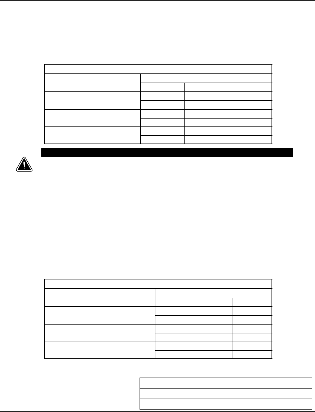
POWER WIRING INSTALLATION NOTES
091505A
164201604---5 8of15
DESCRIPTION:
DATE:
DRAWING NO: SHEET:
REVISION:
Installation Information
A-19
EATON Powerware®9390 UPS (100–160 kVA) Installation and Operation Manual S164201604 Rev B powerware.com
14. External overcurrent protection is not provided by this product, but is required by codes.
Refer to Table E through Table G for wiring requirements. If an output lockable disconnect
is required, it is to be supplied by the user.
15. Table K lists the maximum rating for input circuit breakers. When wiring a single-feed input,
the rating requirements for the input circuit breakers are superceded by the ratings listed in
Tab l e L.
Table K. Maximum Input Circuit Breaker Ratings
UPS Model Input Voltage Rating
208V/220V 480V
Powerware 9390---120/100
Powerware 9390---160/100
80% Rated 450A 200A
100% Rated 350A 150A
Powerware 9390---120/120
Powerware 9390---160/120
80% Rated 500A 225A
100% Rated 450A 175A
Powerware 9390---160/160 80% Rated 700A 300A
100% Rated 600A 250A
CAUTION
To reduce the risk of fire, connect only to a circuit provided with maximum input
circuit breaker current ratings from Table K in accordance with the National Electrical
code, ANSI/NFPA 70.
16. Source protection for the AC input to bypass should be treated as if supplying a 160 kVA
three-phase transformer, to allow for inrush current if an IDC with a transformer is installed.
Bypass input wiring and bypass input breaker rating should be treated as if supplying a
160 kVA load, regardless of the rating of the UPS.
17. The line-to-line unbalanced output capability of the UPS is limited only by the full load
per phase current values for AC output to critical load shown in Table E through Table G.
The recommended line-to-line load unbalance is 50% or less.
18. Bypass and output overcurrent protection and bypass and output disconnect switches are
to be provided by the user. Table L lists the maximum rating for bypass and output circuit
breakers satisfying the criteria for both.
Table L. Maximum Bypass and Output Circuit Breaker Ratings
UPS Model Output Voltage Rating
208V/220V 480V
Powerware 9390---120/100
Powerware 9390---160/100
80% Rated 450A 200A
100% Rated 350A 150A
Powerware 9390---120/120
Powerware 9390---160/120
80% Rated 500A 225A
100% Rated 450A 175A
Powerware 9390---160/160 80% Rated 700A 300A
100% Rated 600A 250A
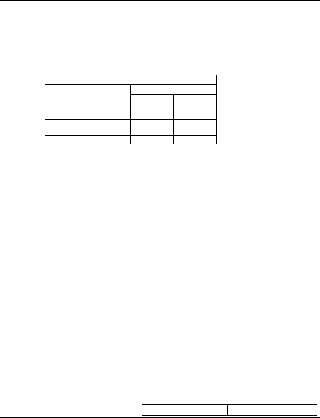
POWER WIRING INSTALLATION NOTES
091505A
164201604---5 9of15
DESCRIPTION:
DATE:
DRAWING NO: SHEET:
REVISION:
Installation Information
A-20 EATON Powerware®9390 UPS (100–160 kVA) Installation and Operation Manual S164201604 Rev B powerware.com
19. There is no DC disconnect device within the UPS.
20. A battery disconnect switch is recommended, and may be required by NEC or local codes
when batteries are remotely located. The battery disconnect switch should be installed
between the battery and the UPS.
21. External DC input overcurrent protection and disconnect switch for the remote battery
location is to be provided by the user. Table M lists the maximum rating for continuous-duty
rated circuit breakers satisfying the criteria for both.
Table M. Maximum DC Input Circuit Breaker Ratings
UPS Model Input Voltage Rating
208V/220V 480V
Powerware 9390---120/100
Powerware 9390---160/100 400A 400A
Powerware 9390---120/120
Powerware 9390---160/120 450A 450A
Powerware 9390---160/160 600A 600A
22. Battery voltage is computed at 2 volts per cell as defined by Article 480 of the NEC.
Rated battery current is computed at 2 volts per cell.
23. The battery wiring used between the battery and the UPS should not allow a voltage drop
of more than 1% of nominal DC voltage at rated battery current.
24. If the conductors used for DC input from the battery cabinets to the UPS are those
provided by the UPS manufacturer, and the UPS and battery cabinets are manufactured by
the same supplier, then it is acceptable if they do not meet the noted minimum conductor
sizes.
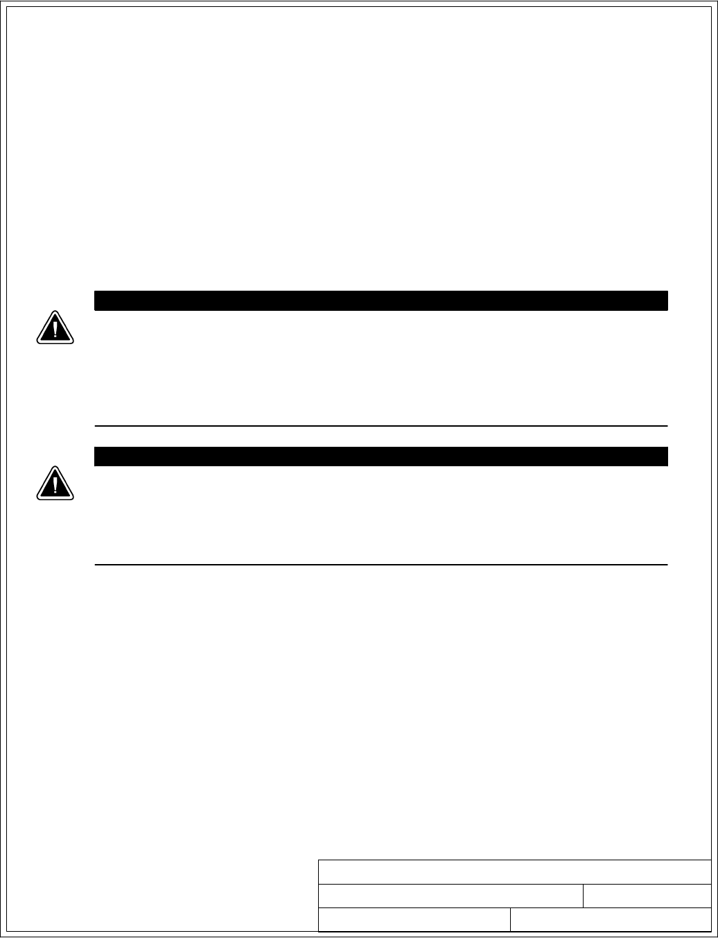
POWER WIRING INSTALLATION NOTES
032406B
164201604---5 10 of 15
DESCRIPTION:
DATE:
DRAWING NO: SHEET:
REVISION:
Installation Information
A-21
EATON Powerware®9390 UPS (100–160 kVA) Installation and Operation Manual S164201604 Rev B powerware.com
25. Parallel system UPM and system bypass input feeds must come from the same source.
26. Parallel UPM input wiring size requirements and output wiring size requirements from the
UPMs to the tie cabinet or distribution panel are the same as listed in Table E through
Tab l e G.
27. If the load requires a neutral, a bypass source neutral must be provided. If the load does
not require a neutral and there is no neutral conductor connected at the bypass input, a
neutral to ground bonding jumper must be installed. Install neutral conductors from the
UPMs to the common point of connection (tie cabinet), and then install a system neutral to
ground bonding jumper. If the recommended installation method cannot be accomplished,
each UPM should have a separate neutral to ground bonding jumper installed in
accordance with Note 7 on page A---13. DO NOT install both a source neutral and a
bonding jumper. See Table O through Table Q for system neutral bonding jumper wire
sizes. Bonding jumper must be copper wire.
CAUTION
HIGH IMPEDANCE GROUND SOURCES - If the source of supply is a high impedance ground (IT)
type, the input neutral conductor must be connected from the source of supply. If there is no
output neutral connected to the UPS, the neutral-forming tranformer kit (PN 103005400) may
be used instead of pulling a neutral from the source. If the load requires a neutral then an
input neutral conductor must be pulled into the UPS. In no circumstances shall a neutral to
ground bonding jumper be installed in the UPS.
CAUTION
DELTA SOURCES (TN-S) - The Powerware 9390 UPS system can be operated only from a delta
supply source that is fully floating and if the neutral-forming transformer kit (PN 103005400) is
installed in the UPS. The UPS cannot be operated from a mid-point or end-point grounded
delta supply source. With this type of supply source, there is no capability to provide an output
neutral. In no circumstances shall a neutral to ground bonding jumper be installed in the UPS.

POWER WIRING INSTALLATION NOTES
091505A
164201604---5 11 of 15
DESCRIPTION:
DATE:
DRAWING NO: SHEET:
REVISION:
Installation Information
A-22 EATON Powerware®9390 UPS (100–160 kVA) Installation and Operation Manual S164201604 Rev B powerware.com
28. See Drawing 164201604---7 for UPM terminal locations and Table H or Table I for
termination requirements.
29. Setup of the CAN Bridge card for parallel operation must be performed by an authorized
Eaton Customer Service Engineer. Contact service to schedule a date.
30. For parallel system circuit breaker ratings, see appropriate information in Table N.
31. For parallel system ratings, see the appropriate information in Table O through Table Q.
Table N. Recommended UPM Output (MOB), Main Output (MIS), and Bypass (MBP)
Circuit Breaker Ratings
UPM Model Configuration
Output Voltage
208V/220V 480V
MOB MIS MBP MOB MIS MBP
9390---120/100
9390---160/100
1+1 500 500 500 200 200 200
2+0 and 2+1 500 1000 1000 200 400 400
3+0 and 3+1 500 1600 1600 200 600 600
4+0 500 2000 2000 200 800 800
9390---120/120
9390---160/120
1+1 500 500 500 200 200 200
2+0 and 2+1 500 1000 1000 200 400 400
3+0 and 3+1 500 1600 1600 200 600 600
4+0 500 2000 2000 200 800 800
9390---160/160
1+1 600 600 600 250 250 250
2+0 and 2+1 600 1200 1200 250 500 500
3+0 and 3+1 600 2000 2000 250 800 800
4+0 600 2400 2400 250 1000 1000

POWER WIRING INSTALLATION NOTES
032406B
164201604---5 12 of 15
DESCRIPTION:
DATE:
DRAWING NO: SHEET:
REVISION:
Installation Information
A-23
EATON Powerware®9390 UPS (100–160 kVA) Installation and Operation Manual S164201604 Rev B powerware.com
Table O. INPUT/OUTPUT Ratings for Powerware 9390---120/100 and 9390---160/100 Parallel Systems
Configuration Units Rating 50/60 Hz
BasicUnitRatingat0.9laggingpFload kVA
kW
100
90
100
90
Input and Bypass Input
Output
VOLTS
VOLTS
208/220
208/220
480
480
All
AC Input from UPM
Full Load Current for each Module
(3) Phases, (1) Neutral --- if required, (1) Ground D
Amps 278/262 120
Minimum Conductor Size for each Module
NumberperPhaseforeachModule
AWG or kcmil
(each)
See Table E through
TableGforwiresize.
1+1
AC Input to Tie Cabinet Bypass (optional)
Full Load Current
(3) Phases, (1) Neutral---if required, (1) Ground
FAmps 278/262 120
AC Output to Critical Load
Full Load Current
(3) Phases, (1) Neutral --- if required, (1) Ground
GAmps 278/262 120
System Neutral Bonding Jumper
Minimum Conductor Size
Number (See Note 27) --- AWG or kcmil
(each)
1/0
(1)
4
(1)
2+0
and
2+1
AC Input to Tie Cabinet Bypass (optional)
Full Load Current
(3) Phases, (1) Neutral---if required, (1) Ground
FAmps 556/524 240
AC Output to Critical Load
Full Load Current
(3) Phases, (1) Neutral --- if required, (1) Ground
GAmps 556/524 240
System Neutral Bonding Jumper
Minimum Conductor Size
Number (See Note 27) --- AWG or kcmil
(each)
3/0
(1)
1/0
(1)
3+0
and
3+1
AC Input to Tie Cabinet Bypass (optional)
Full Load Current
(3) Phases, (1) Neutral---if required, (1) Ground
FAmps 834/786 360
AC Output to Critical Load
Full Load Current
(3) Phases, (1) Neutral --- if required, (1) Ground
GAmps 834/786 360
System Neutral Bonding Jumper
Minimum Conductor Size
Number (See Note 27) --- AWG or kcmil
(each)
1/0
(2)
2/0
(1)
4+0
AC Input to Tie Cabinet Bypass (optional)
Full Load Current
(3) Phases, (1) Neutral---if required, (1) Ground
FAmps 1112/1048 480
AC Output to Critical Load
Full Load Current
(3) Phases, (1) Neutral --- if required, (1) Ground
GAmps 1112/1048 480
System Neutral Bonding Jumper
Minimum Conductor Size
Number (See Note 27) --- AWG or kcmil
(each)
2/0
(2)
2/0
(1)
NOTE: Callout letters D,F,andGmap to Drawing 164201604---4, sheets 4 of 6, 5 of 6,
and 6 of 6.

POWER WIRING INSTALLATION NOTES
032406B
164201604---5 13 of 15
DESCRIPTION:
DATE:
DRAWING NO: SHEET:
REVISION:
Installation Information
A-24 EATON Powerware®9390 UPS (100–160 kVA) Installation and Operation Manual S164201604 Rev B powerware.com
Table P. INPUT/OUTPUT Ratings for Powerware 9390---120/120 and 9390---160/120 Parallel Systems
Configuration Units Rating 50/60 Hz
BasicUnitRatingat0.9laggingpFload kVA
kW
120
108
120
108
Input and Bypass Input
Output
VOLTS
VOLTS
208/220
208/220
480
480
All
AC Input from UPM
Full Load Current for each Module
(3) Phases, (1) Neutral --- if required, (1) Ground D
Amps 333/315 144
Minimum Conductor Size for each Module
NumberperPhaseforeachModule
AWG or kcmil
(each)
See Table E through
TableGforwiresize.
1+1
AC Input to Tie Cabinet Bypass (optional)
Full Load Current
(3) Phases, (1) Neutral---if required, (1) Ground
FAmps 333/315 144
AC Output to Critical Load
Full Load Current
(3) Phases, (1) Neutral --- if required, (1) Ground
GAmps 333/315 144
System Neutral Bonding Jumper
Minimum Conductor Size
Number (See Note 27) --- AWG or kcmil
(each)
1/0
(1)
4
(1)
2+0
and
2+1
AC Input to Tie Cabinet Bypass (optional)
Full Load Current
(3) Phases, (1) Neutral---if required, (1) Ground
FAmps 666/630 288
AC Output to Critical Load
Full Load Current
(3) Phases, (1) Neutral --- if required, (1) Ground
GAmps 666/630 288
System Neutral Bonding Jumper
Minimum Conductor Size
Number (See Note 27) --- AWG or kcmil
(each)
3/0
(1)
1/0
(1)
3+0
and
3+1
AC Input to Tie Cabinet Bypass (optional)
Full Load Current
(3) Phases, (1) Neutral---if required, (1) Ground
FAmps 999/945 432
AC Output to Critical Load
Full Load Current
(3) Phases, (1) Neutral --- if required, (1) Ground
GAmps 999/945 432
System Neutral Bonding Jumper
Minimum Conductor Size
Number (See Note 27) --- AWG or kcmil
(each)
1/0
(2)
2/0
(1)
4+0
AC Input to Tie Cabinet Bypass (optional)
Full Load Current
(3) Phases, (1) Neutral---if required, (1) Ground
FAmps 1332/1260 576
AC Output to Critical Load
Full Load Current
(3) Phases, (1) Neutral --- if required, (1) Ground
GAmps 1332/1260 576
System Neutral Bonding Jumper
Minimum Conductor Size
Number (See Note 27) --- AWG or kcmil
(each)
2/0
(2)
2/0
(1)
NOTE: Callout letters D,F,andGmap to Drawing 164201604---4, sheets 4 of 6, 5 of 6,
and 6 of 6.

POWER WIRING INSTALLATION NOTES
032406B
164201604---5 14 of 15
DESCRIPTION:
DATE:
DRAWING NO: SHEET:
REVISION:
Installation Information
A-25
EATON Powerware®9390 UPS (100–160 kVA) Installation and Operation Manual S164201604 Rev B powerware.com
Table Q. INPUT/OUTPUT Ratings for Powerware 9390---160/160 Parallel System
Configuration Units Rating 50/60 Hz
BasicUnitRatingat0.9laggingpFload kVA
kW
160
144
160
144
Input and Bypass Input
Output
VOLTS
VOLTS
208/220
208/220
480
480
All
AC Input from UPM
Full Load Current for each Module
(3) Phases, (1) Neutral --- if required, (1) Ground D
Amps 444/420 192
Minimum Conductor Size for each Module
NumberperPhaseforeachModule
AWG or kcmil
(each)
See Table E through
TableGforwiresize.
1+1
AC Input to Tie Cabinet Bypass (optional)
Full Load Current
(3) Phases, (1) Neutral---if required, (1) Ground
FAmps 444/420 192
AC Output to Critical Load
Full Load Current
(3) Phases, (1) Neutral --- if required, (1) Ground
GAmps 444/420 192
System Neutral Bonding Jumper
Minimum Conductor Size
Number (See Note 27) --- AWG or kcmil
(each)
2/0
(1)
2
(1)
2+0
and
2+1
AC Input to Tie Cabinet Bypass (optional)
Full Load Current
(3) Phases, (1) Neutral---if required, (1) Ground
FAmps 888/840 384
AC Output to Critical Load
Full Load Current
(3) Phases, (1) Neutral --- if required, (1) Ground
GAmps 888/840 384
System Neutral Bonding Jumper
Minimum Conductor Size
Number (See Note 27) --- AWG or kcmil
(each)
1/0
(2)
1/0
(1)
3+0
and
3+1
AC Input to Tie Cabinet Bypass (optional)
Full Load Current
(3) Phases, (1) Neutral---if required, (1) Ground
FAmps 1332/1260 576
AC Output to Critical Load
Full Load Current
(3) Phases, (1) Neutral --- if required, (1) Ground
GAmps 1332/1260 576
System Neutral Bonding Jumper
Minimum Conductor Size
Number (See Note 27) --- AWG or kcmil
(each)
2/0
(2)
2/0
(1)
4+0
AC Input to Tie Cabinet Bypass (optional)
Full Load Current
(3) Phases, (1) Neutral---if required, (1) Ground
FAmps 1776/1680 768
AC Output to Critical Load
Full Load Current
(3) Phases, (1) Neutral --- if required, (1) Ground
GAmps 1776/1680 768
System Neutral Bonding Jumper
Minimum Conductor Size
Number (See Note 27) --- AWG or kcmil
(each)
3/0
(2)
3/0
(1)
NOTE: Callout letters D,F,andGmap to Drawing 164201604---4, sheets 4 of 6, 5 of 6,
and 6 of 6.
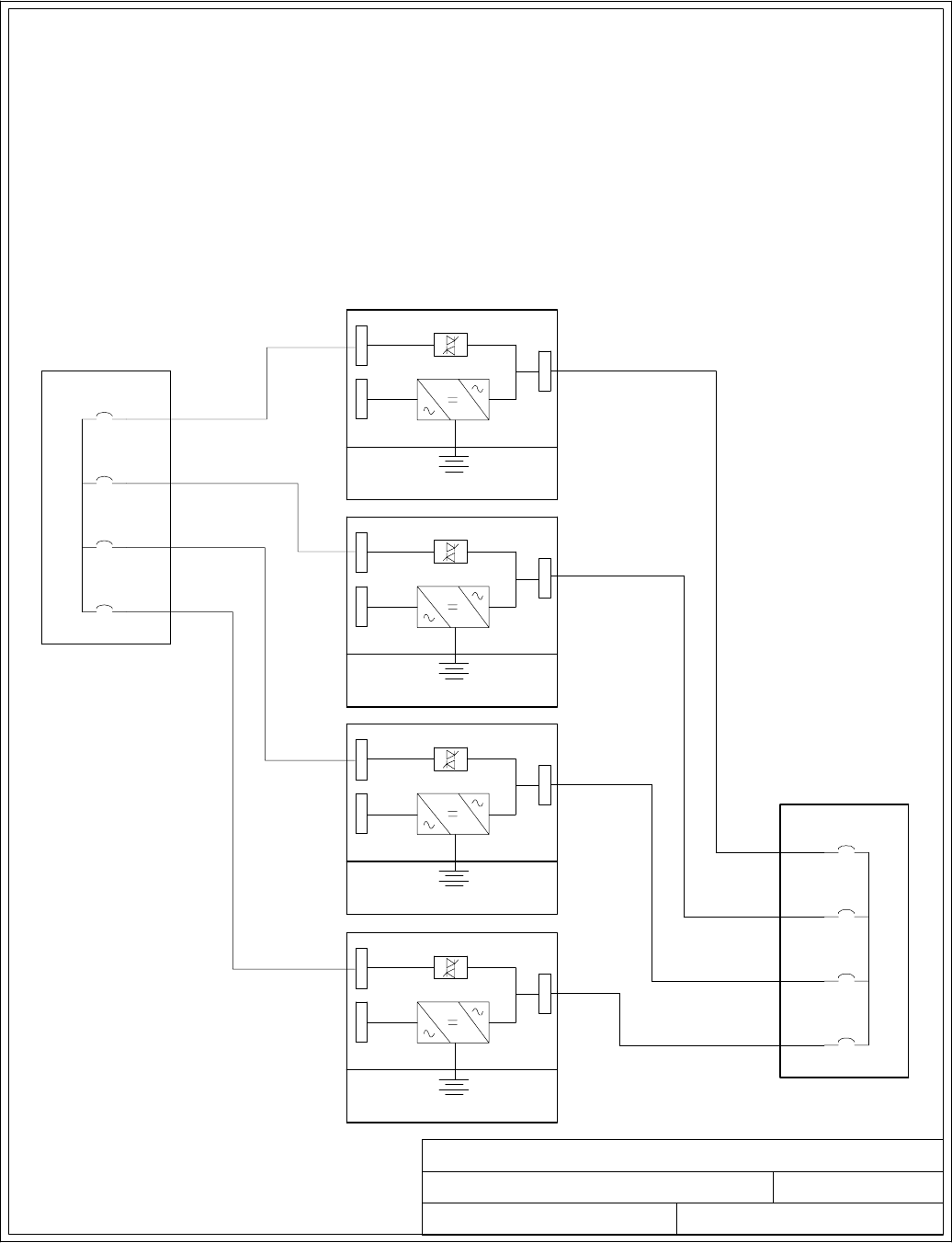
POWER WIRING INSTALLATION NOTES
091505A
164201604---5
DESCRIPTION:
DATE:
DRAWING NO: SHEET:
REVISION:
UPM 2
Battery
Bypass inputs to UPMs
UPM 1
Battery
UPM 3
Battery
UPM 4
Battery
Outputs from UPMs
1A (30)
2A (35)
3A (40)
4A (45)
1B (25)
2B (20)
3B (15)
4B (10)
15 of 15
NOTE: Wire lengths in the diagram and
formula are in feet and are for
example only.
Installation Information
A-26 EATON Powerware®9390 UPS (100–160 kVA) Installation and Operation Manual S164201604 Rev B powerware.com
32. Required parallel system wiring length must be in accordance with the following formula,
as referenced to the diagram below, to ensure approximately equal current sharing when
in Static Bypass mode:
(Total length of 1A + 1B) ≅(Total length of 2A + 2B) ≅(Total length of 3A + 3B) ≅ (Total length of 4A + 4B)
(30 + 25) ≅(35 + 20) ≅(40 + 15) ≅ (45 + 10)
This rule has a tolerance of approximately ±10% for the combined input and output wire
lengths.
If installing only two UPMs in a fully redundant system, this requirement is no longer
required, as each UPM is capable of supporting the full bypass requirement. However, this
would preclude future expansion.
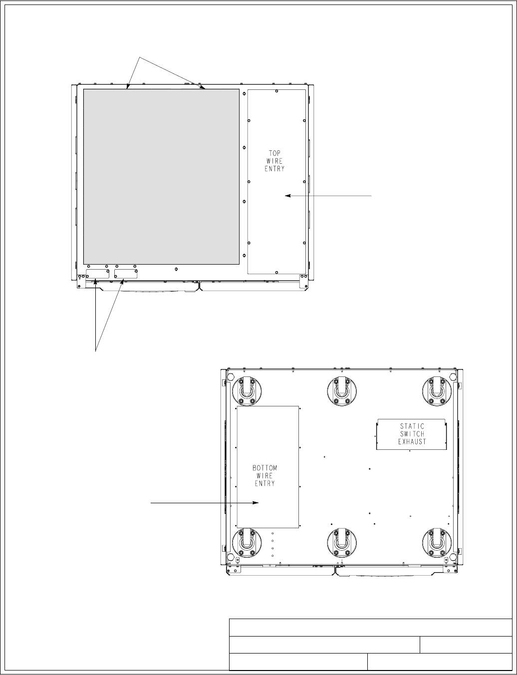
1of2
CONDUIT AND WIRE ENTRY LOCATIONS
091505A
164201604---6
REMOVE DEBRIS SHIELD
COVERING EXHAUST GRILL
BEFORE OPERATING SYSTEM.
TOP ENTRY CONDUIT LANDING
FOR AC INPUT AND OUTPUT,
DC INPUT, DC CONTROL, AND
INTERFACE CONNECTIONS.
(REMOVE PANEL TO DRILL OR
PUNCH CONDUIT HOLES.)
DESCRIPTION:
DATE:
DRAWING NO: SHEET:
REVISION:
BOTTOM ENTRY CONDUIT
LANDING FOR AC INPUT AND
OUTPUT, DC INPUT, DC
CONTROL, AND INTERFACE
CONNECTIONS.
(REMOVE PANEL TO DRILL OR
PUNCH CONDUIT HOLES.)
CONDUIT LANDINGS FOR
X-SLOT CONNECTIONS.
(REMOVE PANELS TO DRILL OR
PUNCH CONDUIT HOLES.)
TOP VIEW
BOTTOM VIEW
Installation Information
A-27
EATON Powerware®9390 UPS (100–160 kVA) Installation and Operation Manual S164201604 Rev B powerware.com
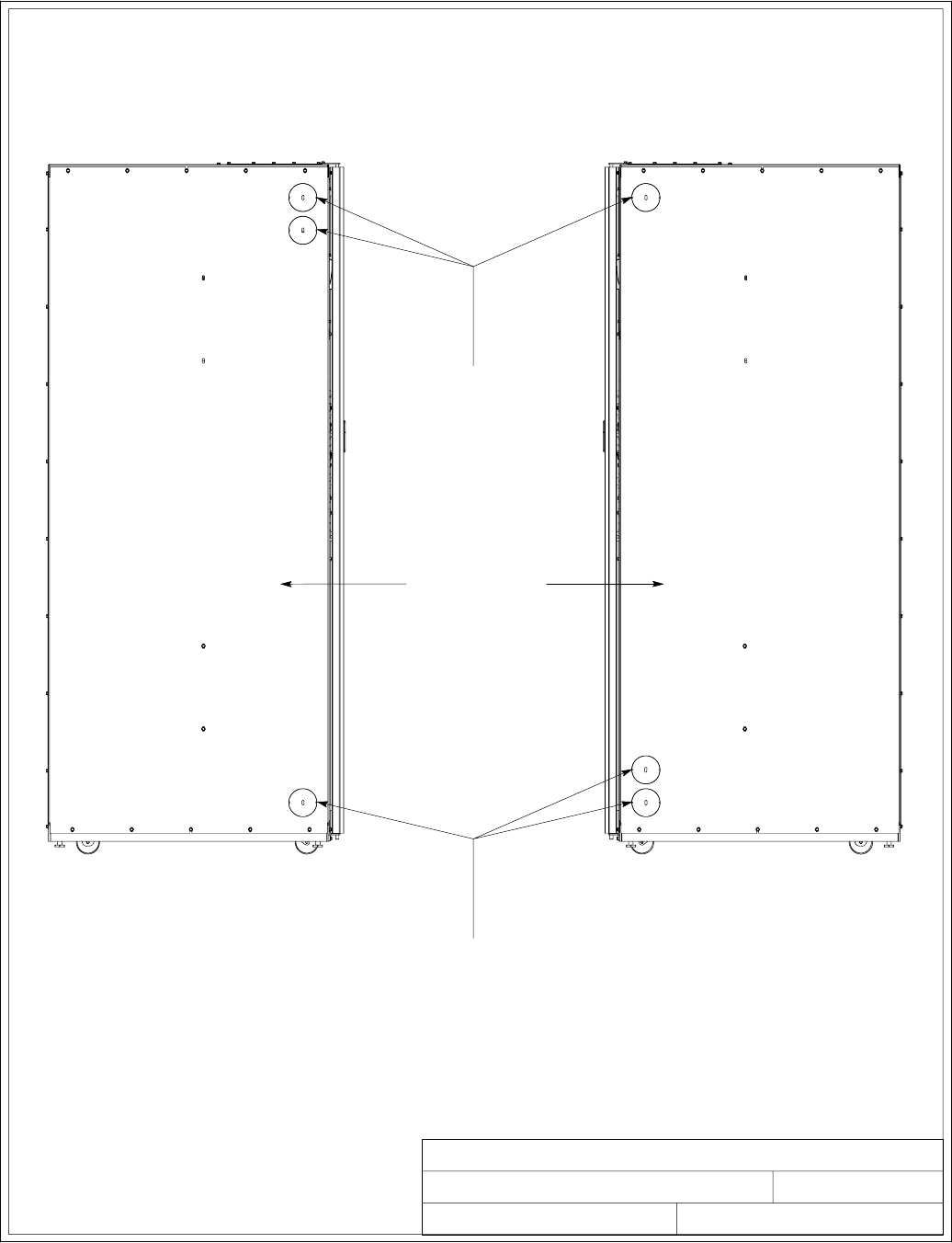
2of2
CONDUIT AND WIRE ENTRY LOCATIONS
091505A
LEFT SIDE VIEW
DESCRIPTION:
DATE:
DRAWING NO: SHEET:
REVISION:
RIGHT SIDE VIEW
INTER-CABINET WIRING ACCESS
KNOCKOUTS. REMOVE KNOCKOUTS,
AS REQUIRED, TO ROUTE WIRES
BETWEEN CABINETS. (INSTALL NYLON
GROMMET AFTER REMOVAL OF
KNOCKOUTS.)
INSIDE PANELS
INTER-CABINET WIRING
ACCESS KNOCKOUTS. REMOVE
KNOCKOUTS, AS REQUIRED, TO
ROUTE WIRES BETWEEN
CABINETS. (INSTALL NYLON
GROMMET AFTER REMOVAL OF
KNOCKOUTS.)
164201604---6
Installation Information
A-28 EATON Powerware®9390 UPS (100–160 kVA) Installation and Operation Manual S164201604 Rev B powerware.com
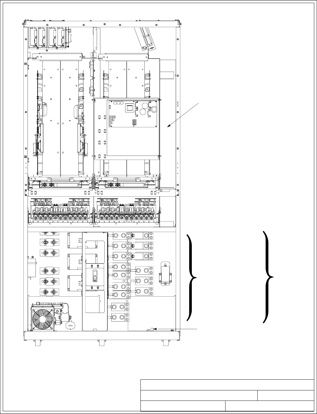
1of4
UPS POWER TERMINAL LOCATIONS
032406B
164201604---7
NOTE: Metal shields covering wiring
terminals must be removed or
opened to gain access to
terminals.
GROUND TERMINALS
AC INPUT TO UPS
RECTIFIER AND BYPASS
(A,B,C,N)
DESCRIPTION:
DATE:
DRAWING NO: SHEET:
REVISION:
DC INPUT FROM BATTERY
TO UPS
( + A N D --- )
AC OUTPUT TO CRITICAL
LOAD
(A,B,C,N)
WIREWAY FOR TOP
ENTRY POWER WIRING
SEE SHEET 2
FOR DETAILS
MODELS 120/100 AND 120/120
480V INPUT AND 480V OUTPUT
Installation Information
A-29
EATON Powerware®9390 UPS (100–160 kVA) Installation and Operation Manual S164201604 Rev B powerware.com
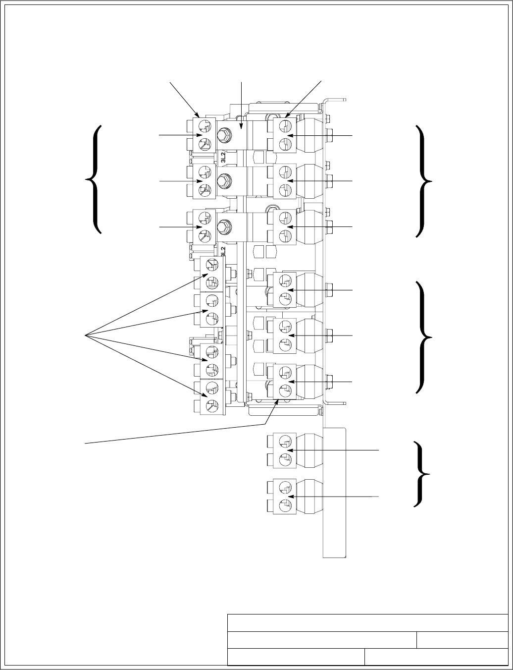
2of4
UPS POWER TERMINAL LOCATIONS
091505A
164201604---7
TERMINAL DETAIL
PHASE A (E9)
PHASE B (E10)
PHASE C (E11)
DESCRIPTION:
DATE:
DRAWING NO: SHEET:
REVISION:
AC OUTPUT TO
CRITICAL LOAD
DC INPUT
FROM BATTERY
+
(E4)
---
(E5)
PHASE A (E1)
PHASE B (E2)
PHASE C (E3)
PHASE A (E6)
PHASE B (E7)
PHASE C (E8)
NEUTRAL
TERMINALS
(E12)
RECTIFIER INPUT
TERMINALS
BYPASS INPUT
TERMINALS
OUTPUT
TERMINALS
SINGLE-FEED
JUMPERS
AC INPUT TO UPS
BYPASS
(DUAL INPUT) AC INPUT TO
UPS RECTIFIER
(DUAL INPUT)
RIGHT SIDE VIEW
MODELS 120/100 AND 120/120
480V INPUT AND 480V OUTPUT
AC INPUT TO
UPS RECTIFIER
AND BYPASS
(SINGLE INPUT)
Installation Information
A-30 EATON Powerware®9390 UPS (100–160 kVA) Installation and Operation Manual S164201604 Rev B powerware.com
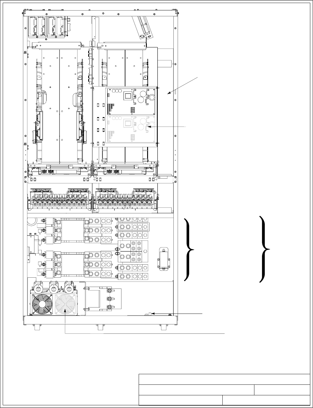
3of4
UPS POWER TERMINAL LOCATIONS
032406B
164201604---7
GROUND TERMINALS
WIREWAY FOR TOP
ENTRY POWER WIRING
NOTE: Metal shields covering wiring
terminals must be removed or
opened to gain access to
terminals.
DESCRIPTION:
DATE:
DRAWING NO: SHEET:
REVISION:
AC INPUT TO UPS
RECTIFIER AND BYPASS
(A,B,C,N)
DC INPUT FROM BATTERY
TO UPS
( + A N D --- )
AC OUTPUT TO CRITICAL
LOAD
(A,B,C,N)
SEE SHEET 4
FOR DETAILS
MODELS 120/100, 120/120, 160/100, 160/120, AND 160/160
208V/220V INPUT AND 208V/220V OUTPUT
MODELS 160/100, 160/120, AND 160/160
480V INPUT AND 480V OUTPUT
NOT USED ON 120/100 AND
120/120 208V/220V RATINGS
USED ONLY ON 160/100,
160/120, AND 160/160
208V/220V RATINGS
Installation Information
A-31
EATON Powerware®9390 UPS (100–160 kVA) Installation and Operation Manual S164201604 Rev B powerware.com
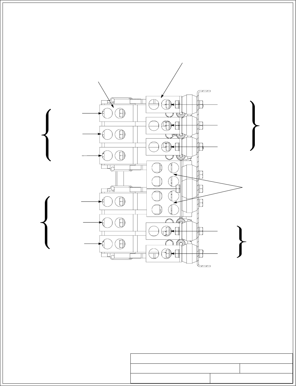
4of4
UPS POWER TERMINAL LOCATIONS
091505A
164201604---7
DESCRIPTION:
DATE:
DRAWING NO: SHEET:
REVISION:
RECTIFIER INPUT
TERMINALS
BYPASS INPUT
TERMINALS
DC INPUT
FROM BATTERY
+
(E4)
---
(E5)
AC INPUT TO
UPS BYPASS
(DUAL INPUT)
AC INPUT TO
UPS RECTIFIER
AND BYPASS
(SINGLE INPUT)
AC INPUT TO
UPS RECTIFIER
(DUAL INPUT)
PHASE A (E6)
PHASE B (E7)
PHASE C (E8)
PHASE A (E9)
PHASE B (E10)
PHASE C (E11)
AC OUTPUT TO
CRITICAL LOAD
NEUTRAL
TERMINALS
(E12)
PHASE A (E1)
PHASE B (E2)
PHASE C (E3)
TERMINAL DETAIL
RIGHT SIDE VIEW
MODELS 120/100, 120/120, 160/100, 160/120, AND 160/160
208V/220V INPUT AND 208V/220V OUTPUT
MODELS 160/100, 160/120, AND 160/160
480V INPUT AND 480V OUTPUT
Installation Information
A-32 EATON Powerware®9390 UPS (100–160 kVA) Installation and Operation Manual S164201604 Rev B powerware.com

1of13
INTERFACE WIRING INSTALLATION
NOTES AND TERMINAL LOCATIONS
032406B
DESCRIPTION:
DATE:
DRAWING NO: SHEET:
REVISION:
164201604---8
Installation Information
A-33
EATON Powerware®9390 UPS (100–160 kVA) Installation and Operation Manual S164201604 Rev B powerware.com
1. Use Class 1 wiring methods (as defined by the NEC) for interface wiring up to 30V. The
wire should be rated at 24V, 1A minimum.
2. Use Class 2 wiring methods (as defined by the NEC) for interface wiring from 30 to 600V.
3. When installing external interface wiring (for example, building alarm, relay output, battery
breaker trip, and X-Slot) to the UPS interface terminals, conduit must be installed between
each device and the UPS cabinet. Install the interface wiring in separate conduit from the
power wiring.
4. When installing internal interface wiring to X-Slot terminals, route the wiring through the
internal opening in the X-Slot communication bay.
5. All building alarm inputs or remote features require an isolated normally-open contact or
switch (rated at 24 Vdc, 20 mA minimum) connected between the alarm input and
common terminal as shown. All control wiring and relay and switch contacts are
customer-supplied. Use twisted-pair wires for each alarm input and common.
6. The building alarms can be programmed to display the alarm functional name.
7. See Table R through Table X and Chapters 3, 5, and 6 for customer interface wiring.
8. LAN and telephone drops for use with X-Slot connectivity cards must be provided by
facility planners or the customer.
Table R. TB1 and TB2 Interface Connections
Termina l T B 1 Name Description
1Remote EPO NC Normally-closed dry contacts used to activate EPO
of UPS from a remote switch
2Remote EPO Common
3Remote EPO NO Normally-open dry contacts used to activate EPO of
UPS from a remote switch
4Remote EPO Common
5Battery Breaker Aux Contacts used to indicate whether UPS battery
breaker or disconnect is open or closed.
6Battery Breaker Aux
Return
7Battery UVR (+) Contacts used to open battery breaker or
disconnect.
8Battery UVR (---)
9Building Alarm 1 Programmable UPS alarm. Activated by a remote
dry contact closure.
10 Building Alarm 1 Return
Termina l T B 2 Name Description
1Building Alarm 2 Programmable UPS alarm. Activated by a remote
dry contact closure. Also used for backup control
(pull chain) for parallel operation.
2Building Alarm 2 Return
3On Bypass Return Normally-open contact closes when UPS is on
bypass. Also used for backup control (pull chain)
for parallel operation.
4On Bypass NO
5Alarm Relay NC General purpose normally-closed relay contact.
6Alarm Relay Common
7Alarm Relay NO General purpose normally-open relay contact.
8Alarm Relay Common
9On Inverter NC Normally-closed contact opens when output
contactor closes.
10 On Inverter Return
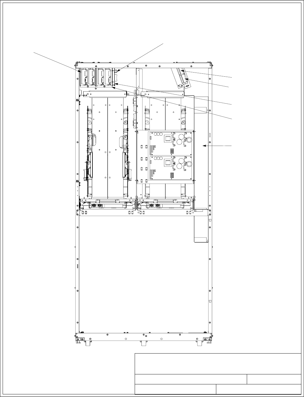
032406B
164201604---8
DESCRIPTION:
DATE:
DRAWING NO: SHEET:
REVISION:
INTERFACE WIRING INSTALLATION
NOTES AND TERMINAL LOCATIONS
TB1
TB2
X-SLOTS
STANDARD
X-SLOT COMMUNICATION BAY
WIREWAY FOR BOTTOM ENTRY
INTERFACE WIRING
NOTE: Metal shields covering wiring
terminals must be removed or
opened to gain access to
terminals.
1234
INTERFACE TERMINAL LOCATIONS
OPTIONAL X-SLOT
COMMUNICATION BAY
OPTIONAL MINI-CSB
MINI-CSB BUILDING
ALARM TERMINAL
BLOCK P5
2of13
Installation Information
A-34 EATON Powerware®9390 UPS (100–160 kVA) Installation and Operation Manual S164201604 Rev B powerware.com
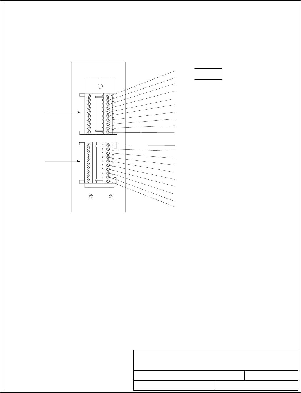
NOTE: 1. All building alarm inputs require an isolated normally-open or
normally-closed contact or switch (rated at 24 Vdc, 20 mA minimum)
connected between the alarm input and common terminal as shown. Building
alarm inputs can be programmed for use with either normally-open or
normally-closed contacts. All control wiring and relay and switch contacts are
customer-supplied.
2. The building alarms can be programmed to display the alarm functional
name.
3. A jumper wire must be connected between pins 1 and 2 on TB1, if the
normally-closed EPO contact is not used.
032406B
164201604---8
DESCRIPTION:
DATE:
DRAWING NO: SHEET:
REVISION:
INTERFACE WIRING INSTALLATION
NOTES AND TERMINAL LOCATIONS
INTERFACE TERMINALS
3of13
BUILDING ALARM 2 RETURN
BUILDING ALARM 1
1
10
1
10
TB1
TB2
BUILDING ALARM 1 RETURN
BUILDING ALARM 2
ALARM RELAY NC
ALARM RELAY COMMON
ALARM RELAY NO
REMOTE EPO NO
REMOTE EPO NC
EPO COMMON
BATTERY BREAKER AUX
BATTERY BREAKER AUX RETURN
BATTERY UVR (+)
B A T T E R Y U V R ( --- )
UPS
ON BYPASS NO
ON BYPASS RETURN
ON INVERTER NC
ON INVERTER RETURN
EPO COMMON
ALARM RELAY COMMON
JUMPER REQUIRED
IF NOT USED
Installation Information
A-35
EATON Powerware®9390 UPS (100–160 kVA) Installation and Operation Manual S164201604 Rev B powerware.com
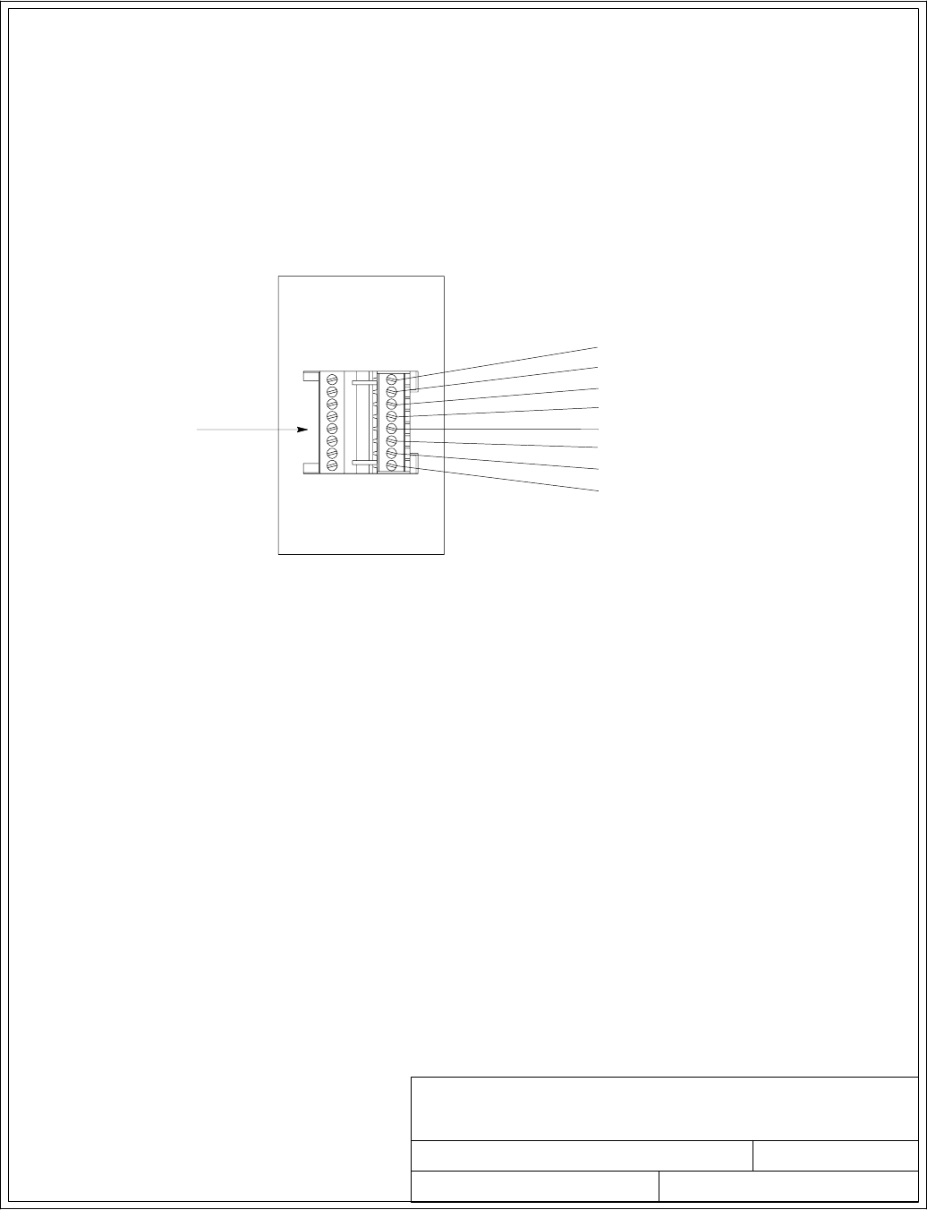
091505A
164201604---8
DESCRIPTION:
DATE:
DRAWING NO: SHEET:
REVISION:
INTERFACE WIRING INSTALLATION
NOTES AND TERMINAL LOCATIONS
NOTE: 1. All building alarm inputs require an isolated normally-open or
normally-closed contact or switch (rated at 24 Vdc, 20 mA minimum)
connected between the alarm input and common terminal as shown. Building
alarm inputs can be programmed for use with either normally-open or
normally-closed contacts. All control wiring and relay and switch contacts are
customer-supplied.
2. The building alarms can be programmed to display the alarm functional
name.
MINI-CSB INTERFACE TERMINALS
4of13
1
8
P5
BUILDING ALARM 3
BUILDING ALARM 3 RETURN
MINI-CSB
BUILDING ALARM 4
BUILDING ALARM 5
BUILDING ALARM 6
BUILDING ALARM 4 RETURN
BUILDING ALARM 5 RETURN
BUILDING ALARM 6 RETURN
Installation Information
A-36 EATON Powerware®9390 UPS (100–160 kVA) Installation and Operation Manual S164201604 Rev B powerware.com
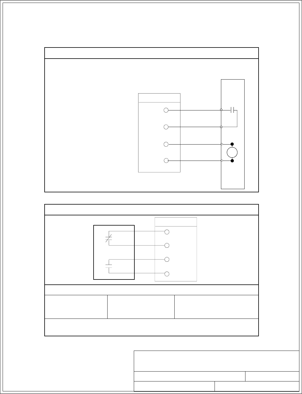
032406B
164201604---8
DESCRIPTION:
DATE:
DRAWING NO: SHEET:
REVISION:
INTERFACE WIRING INSTALLATION
NOTES AND TERMINAL LOCATIONS
5of13
Installation Information
A-37
EATON Powerware®9390 UPS (100–160 kVA) Installation and Operation Manual S164201604 Rev B powerware.com
9. The UPS DC UVR trip and Battery Aux signal wiring from the UPS must be connected to
the DC source disconnect device.
10. Battery Aux and UVR wiring should be a minimum of 18 AWG.
Table S. Battery Disconnect Interface
B
A
TTER
Y
BREAKER OR
DISCONNECT
6
7
8
TB1
BATTERY AUX + 5
B A T T E R Y A U X ---
BATTERY UVR +
B AT T E R Y U V R ---
UPS
Table T. Alarm Relay Contact
5
5
7
ALARM RELAY TB2
8
UPS
CONTACT RATING
Switched Voltage:
277 Vac
28 Vdc
Maximum Current: 5A Minimum Wire Size: 22 AWG
NOTE: Relays are shown in de-energized state. Relays change state when the
UPS is in Normal mode.
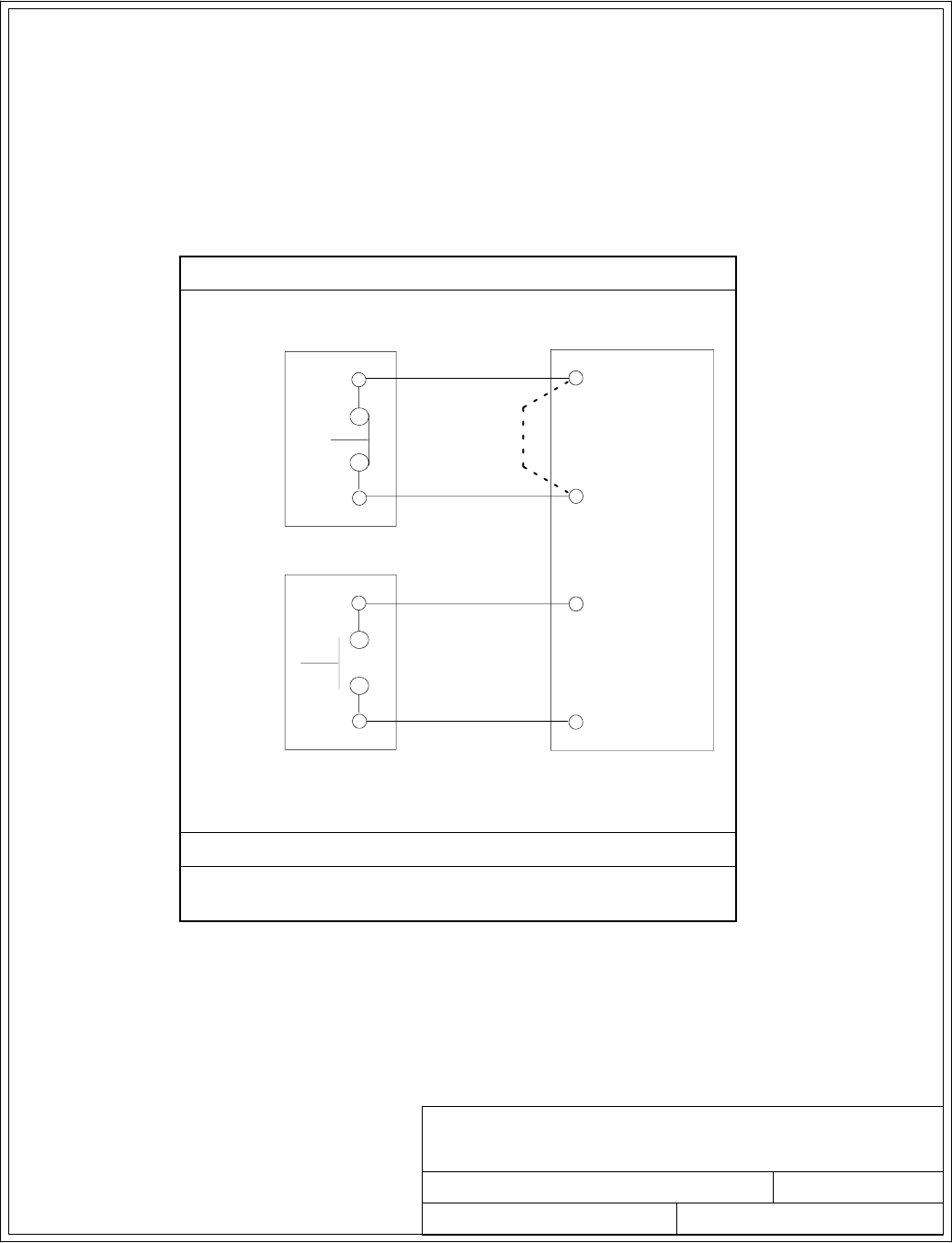
032406B
164201604---8
DESCRIPTION:
DATE:
DRAWING NO: SHEET:
REVISION:
INTERFACE WIRING INSTALLATION
NOTES AND TERMINAL LOCATIONS
6of13
Installation Information
A-38 EATON Powerware®9390 UPS (100–160 kVA) Installation and Operation Manual S164201604 Rev B powerware.com
11. The Remote EPO feature opens all contactors in the UPS cabinet and isolates power from
your critical load. Local electrical codes may also require tripping upstream protective
devices to the UPS. This switch must be a dedicated latching-type switch not tied into any
other circuit.
12. A jumper wire must be connected between pins 1 and 2 on TB1, if a normally-closed EPO
switch is not used or a normally-open EPO switch is used.
13. Remote EPO wiring should be a minimum of 22 AWG.
TableU.RemoteEPO
1(NC)
4 (COMMON)
TWISTED
WIRES
UPS TB1
REMOTE
EPO
SWITCH
REMOTE
EPO
SWITCH
2 (COMMON)
3(NO)
(NC TYPE)
(NO TYPE)
TWISTED
WIRES
OR
LATCHING-TYPE
SWITCH ONLY
INSTALL JUMPER
IF SWITCH NOT
INSTALLED THIS
POSITION
SWITCH ONLY
LATCHING-TYPE
Remote EPO switch rating is 24 Vdc, 1A minimum.
NOTE: This switch must be a dedicated latching-type switch not
tied into any other circuits.
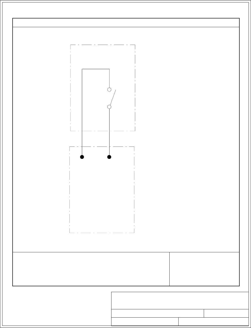
032406B
164201604---8
DESCRIPTION:
DATE:
DRAWING NO: SHEET:
REVISION:
INTERFACE WIRING INSTALLATION
NOTES AND TERMINAL LOCATIONS
7of13
Installation Information
A-39
EATON Powerware®9390 UPS (100–160 kVA) Installation and Operation Manual S164201604 Rev B powerware.com
14. Wire the maintenance bypass auxiliary contacts as applicable. See Table V.
Table V. Typical Maintenance Bypass Panel Auxiliary Contact Control Wiring
TB2
34
MAINTENANCE BYPASS PANEL
(PROVIDED BY OTHERS)
UPS
NOTE: REFER TO THE INSTRUCTIONS
PROVIDED WITH THE MAINTENANCE
BYPASS PANEL FOR WIRING INSTRUCTIONS.
MBP
AUX 1
N. O.
COMMON
AUX CONTACT RATING
Refer to the instructions provided with the maintenance bypass panel
for auxiliary contact ratings. Minimum Wire Size: 22 AWG
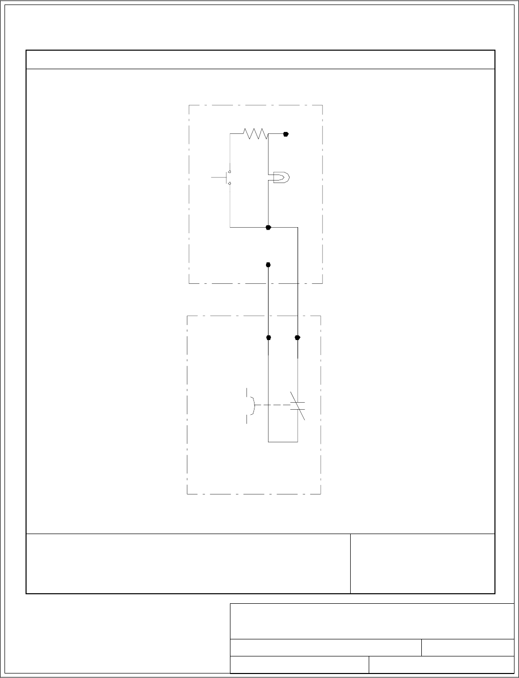
091505A
164201604---8
DESCRIPTION:
DATE:
DRAWING NO: SHEET:
REVISION:
INTERFACE WIRING INSTALLATION
NOTES AND TERMINAL LOCATIONS
8of13
Installation Information
A-40 EATON Powerware®9390 UPS (100–160 kVA) Installation and Operation Manual S164201604 Rev B powerware.com
15. 120 Vac should be provided from the critical bus by facility planners or the customer. See
Tab l e W.
Table W. Typical Maintenance Bypass Panel Key Switch Control Wiring
Neutral
Key
Switch
Lamp
120 VAC
Fused
TB2
Output
Contactor
K3
910
Solenoid
MAINTENANCE BYPASS PANEL
(PROVIDED BY OTHERS)
UPS
NOTE:THEREDOKTOGOTO
MAINTENANCE BYPASS
ILLUMINATES ONLY WHEN THE
UPS MODULE IS NOT ONLINE (K3
OUTPUT CONTACTOR IS OPEN).
K3 AUX CONTACT RATING
Switched Voltage: 120 Vac at 6A Maximum
240 Vac at 4A Maximum
24 Vdc at 6A Maximum
Minimum Wire Size: 22 AWG
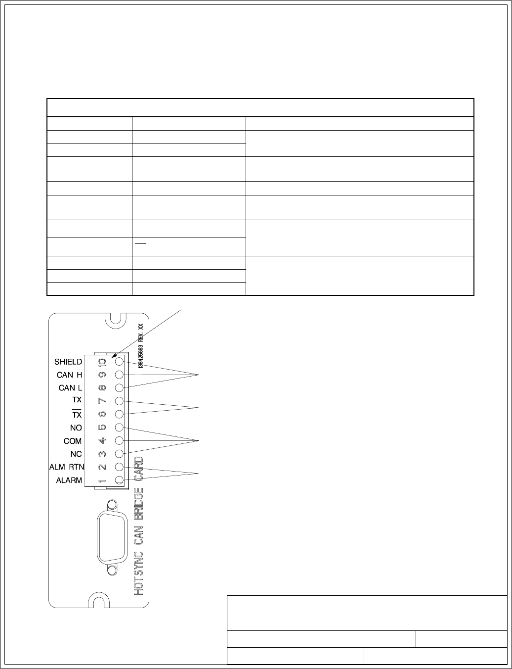
091505A
164201604---8
DESCRIPTION:
DATE:
DRAWING NO: SHEET:
REVISION:
INTERFACE WIRING INSTALLATION
NOTES AND TERMINAL LOCATIONS
POWERWARE HOT SYNC CAN BRIDGE CARD
CONNECTIONS FOR PARALLEL SYSTEM CONTROL
CONNECTIONS FOR RMP II, RIM II, OR SCM II
BUILDING ALARM 2 REPLACEMENT
J3
NOTE: All interface wiring is to be provided
by the customer.
CONNECTIONS FOR BYPASS STATUS
9of13
Installation Information
A-41
EATON Powerware®9390 UPS (100–160 kVA) Installation and Operation Manual S164201604 Rev B powerware.com
16. Conduit must be installed between the UPM cabinets for parallel interface wiring. Install the
interface wiring in separate conduit from the power wiring.
17. Use Class 1 wiring methods (as defined by the NEC) for parallel interface wiring. The wire
should be shielded twisted pair, rated for 5 amps maximum.
18. See Table X and Chapter 6 for Powerware Hot Sync CAN Bridge Card interface wiring.
Table X. Powerware Hot Sync CAN Bridge Card Interface Connections
Termina l J 3 Name Description
1Alarm Programmable UPS alarm. Activated by a remote
dry contact closure.
2Alarm Rtn
3Alarm Relay NC Normally-closed contact opens when UPS is on
bypass.
4Alarm Relay Com Bypass contact return.
5Alarm Relay NO Normally-open contact closes when UPS is on
bypass.
6TX Remote Monitor Panel II (RMP II), Relay Interface
Module II (RIM II), and Supervisory Contact
Module II (SCM II) connections.
7TX
8CAN L Computer Area Network (CAN) Input for parallel
operation.
9CAN H
10 Shield
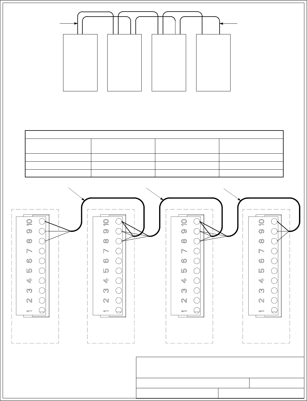
091505A
164201604---8
DESCRIPTION:
DATE:
DRAWING NO: SHEET:
REVISION:
INTERFACE WIRING INSTALLATION
NOTES AND TERMINAL LOCATIONS
NOTE: This drawing is for parallel wiring purposes and is not a floor layout plan.
UPMs can be placed in any physical order.
PARALLEL SYSTEM CAN AND BACKUP CONTROL (PULL CHAIN)
UPM
1
UPM
2
UPM
3
UPM
4
CAN
(IF INSTALLED) (IF INSTALLED)
PULL CHAIN
PARALLEL SYSTEM CAN WIRING
10 of 13
TWISTED PAIR
TWISTED PAIR TWISTED PAIR
UPM 1
CAN CARD J3
UPM 2
CAN CARD J3
UPM 3
CAN CARD J3
(IF INSTALLED)
UPM 4
CAN CARD J3
(IF INSTALLED)
Installation Information
A-42 EATON Powerware®9390 UPS (100–160 kVA) Installation and Operation Manual S164201604 Rev B powerware.com
CAN Wiring Terminations
From UPM 1 CAN Card To UP M 2 C AN Card To UPM 3 CAN C a r d
(If Installed)
To UPM 4 C A N C a rd
(If Installed)
J3–8 (L) J3–8 (L) J3–8 (L) J3–8 (L)
J3–9 (H) J3–9 (H) J3–9 (H) J3–9 (H)
J3–10 (Shield) J3–10 (Shield) J3–10 (Shield) J3–10 (Shield)
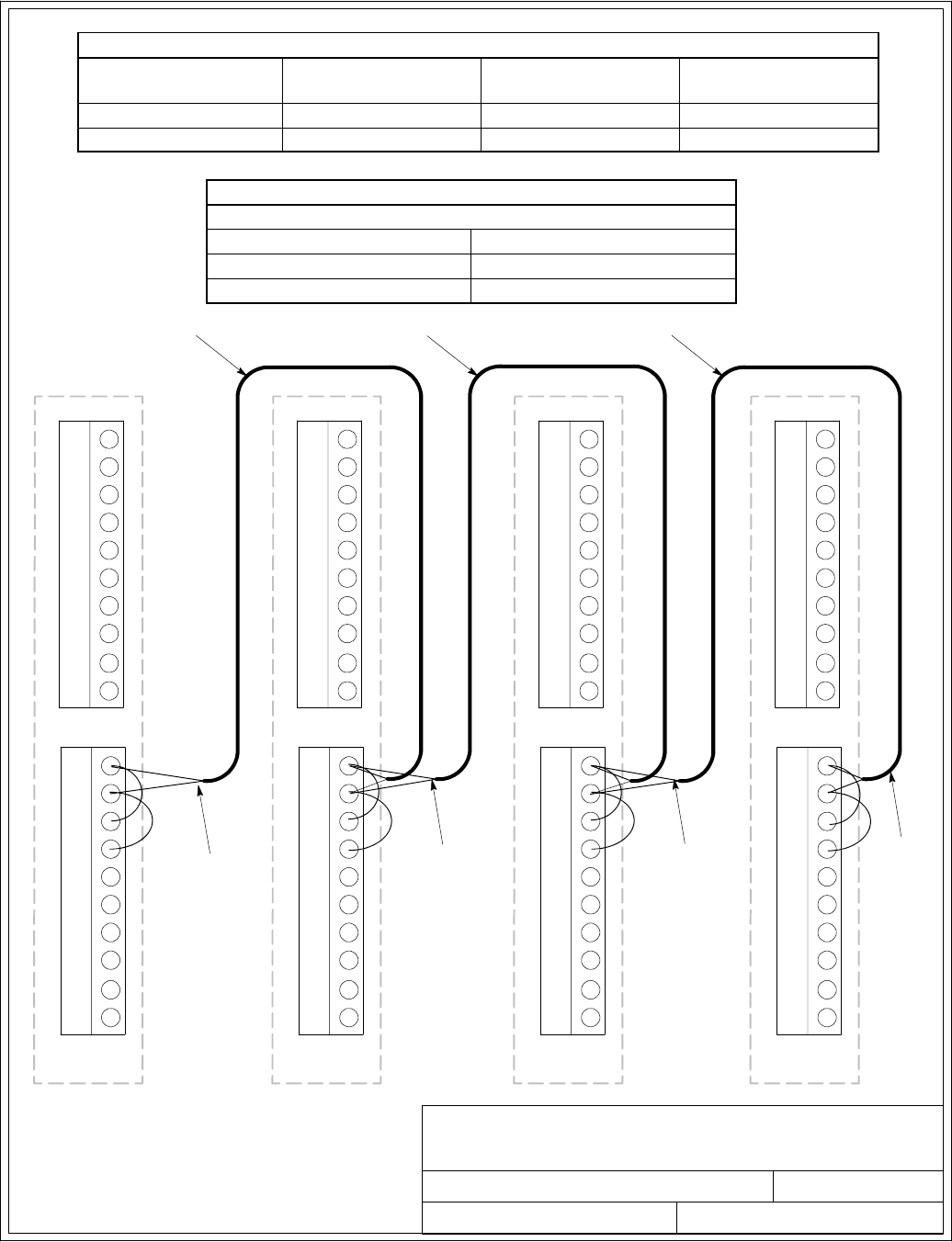
Installation Information
A-43
EATON Powerware®9390 UPS (100–160 kVA) Installation and Operation Manual S164201604 Rev B powerware.com
Building Alarm Pull Chain Wiring Terminations
From UPM 1 To UPM 2 To UPM 3
(If Installed)
To UPM 4
(If Installed)
TB2–1 (BA 2) TB2–1 (BA 2) TB2–1 (BA 2) TB2–1 (BA 2)
TB2–2 (Rtn) TB2–2 (Rtn) TB2–2 (Rtn) TB2–2 (Rtn)
Bypass Relay Pull Chain Wiring Terminations
All UPMs
From To
TB2–1 (BA 2) TB2–3 (Byp)
TB2–2(BA2Rtn) TB2–4 (Byp Rtn)
032406B
164201604---8
DESCRIPTION:
DATE:
DRAWING NO: SHEET:
REVISION:
INTERFACE WIRING INSTALLATION
NOTES AND TERMINAL LOCATIONS
PARALLEL SYSTEM BACKUP
CONTROL (PULL CHAIN)
WIRING
11 of 13
1
2
3
4
5
7
8
6
TB1
9
10
TB2
UPM 1
TWISTED PAIR TWISTED PAIR TWISTED PAIR
TWISTED
PAIR
TWISTED
PAIR
TWISTED
PAIR
1
2
3
4
5
7
8
6
9
10
1
2
3
4
5
7
8
6
TB1
9
10
TB2
UPM 2
1
2
3
4
5
7
8
6
9
10
1
2
3
4
5
7
8
6
TB1
9
10
TB2
UPM 3
(IF INSTALLED)
1
2
3
4
5
7
8
6
9
10
1
2
3
4
5
7
8
6
TB1
9
10
TB2
1
2
3
4
5
7
8
6
9
10
TWISTED
PAIR
UPM 4
(IF INSTALLED)
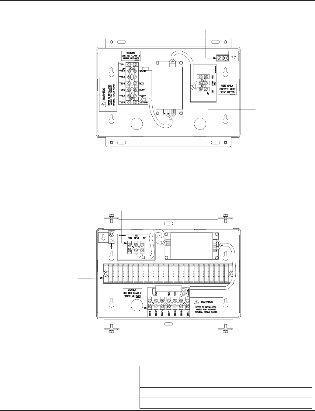
091505A
164201604---8
DESCRIPTION:
DATE:
DRAWING NO: SHEET:
REVISION:
INTERFACE WIRING INSTALLATION
NOTES AND TERMINAL LOCATIONS
TERMINAL TB–1
SIGNAL CONNECTIONS
FROM THE UPS
GROUND
TERMINAL
REMOTE MONITOR PANEL AND RELAY
INTERFACEMODULETERMINALLOCATIONS
TERMINAL TB–3
120 VAC POWER
SUPERVISORY CONTACT MODULE
TERMINAL LOCATIONS
GROUND
TERMINAL
TERMINAL TB–1
SIGNAL CONNECTIONS
FROM THE UPS
TERMINAL TB–3
120 VAC POWER
TERMINAL TB–2
CUSTOMER SUPERVISORY
CONTACT INTERFACE
12 of 13
Installation Information
A-44 EATON Powerware®9390 UPS (100–160 kVA) Installation and Operation Manual S164201604 Rev B powerware.com
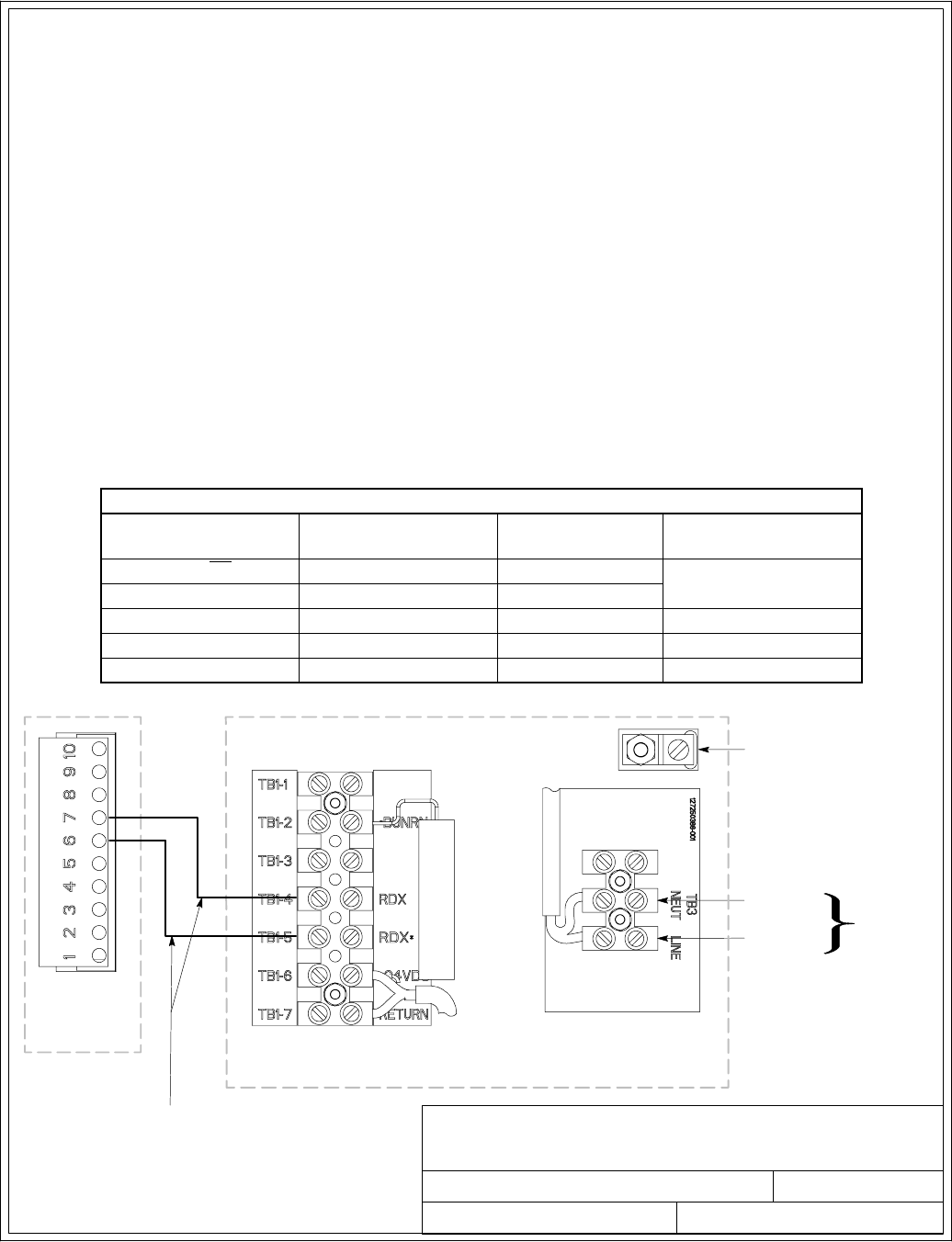
091505A
164201604---8
DESCRIPTION:
DATE:
DRAWING NO: SHEET:
REVISION:
INTERFACE WIRING INSTALLATION
NOTES AND TERMINAL LOCATIONS
UPS CAN
CARD J3
120 VAC
FROM
CRITICAL
BUS
LINE
NEUTRAL
TWISTED PAIR
GROUND
TERMINAL
RMP II, RIM II, OR SCM II
13 of 13
Installation Information
A-45
EATON Powerware®9390 UPS (100–160 kVA) Installation and Operation Manual S164201604 Rev B powerware.com
19. Conduit must be installed between the UPS cabinet and the RMP II, RIM II, or SCM II for
signal wiring. Conduit must be installed between the device and the power source for
power wiring. Install the signal wiring in separate conduit from the power wiring.
20. Conduit and wiring between the UPS and the RMP II, RIM II, or SCM II is to be supplied by
the customer.
21. Maximum distance between the UPS cabinet and RMP II, RIM II, or SCM II is not to exceed
500 feet.
22. Use Class 1 wiring methods (as defined by the NEC) for RMP II, RIM II, or SCM II power
and signal wiring. Power wiring should be a minimum of 22 AWG and a maximum of
14AWG.Thewireshouldberatedfor1Aminimum.
23. RMP II, RIM II, or SCM II signal wiring should be a minimum of 22 AWG and a maximum of
14AWG.Thewireshouldbetwistedpair,ratedfor5Amaximum.
24. Use only 75°C copper wire.
25. 120 Vac for the RMP II, RIM II, or SCM II should be provided from the critical bus by facility
planners or the customer.
26. See Table X and Chapter 6 for CAN Bridge Card and RMP II, RIM II, or SCM II installation.
RMP, RIM, or SCM Wiring Terminations
From UPS CAN Card To RMP, RIM, or SCM Tightening Torque
Nm (lb in) Remarks
J3–6 (TX)TB1–5 (RDX*)0.9 (8) Use Twisted Pair
J3–7 (TX) TB1–4 (RDX) 0.9 (8)
N/A TB3 Line 0.9 (8)
N/A TB3 Neutral 0.9 (8)
N/A Ground Terminal 2.7 (24) Maximum
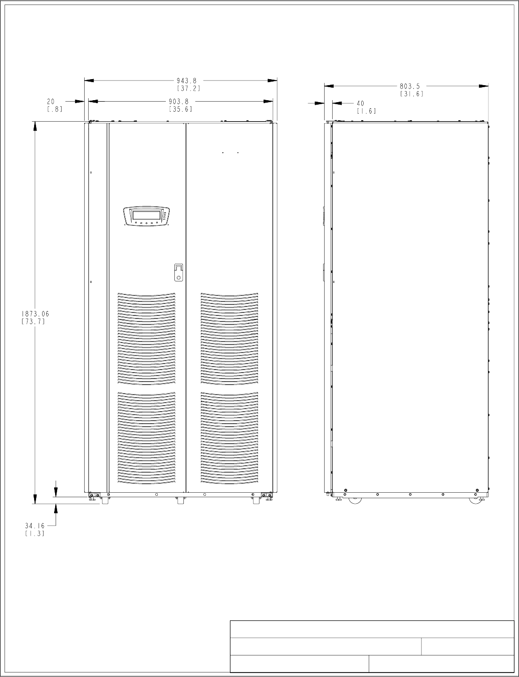
1of4
UPS CABINET DIMENSIONS
091505A
164201604---9
FRONT VIEW RIGHT SIDE VIEW
DESCRIPTION:
DATE:
DRAWING NO: SHEET:
REVISION:
Dimensions are in millimeters [inches]
Installation Information
A-46 EATON Powerware®9390 UPS (100–160 kVA) Installation and Operation Manual S164201604 Rev B powerware.com
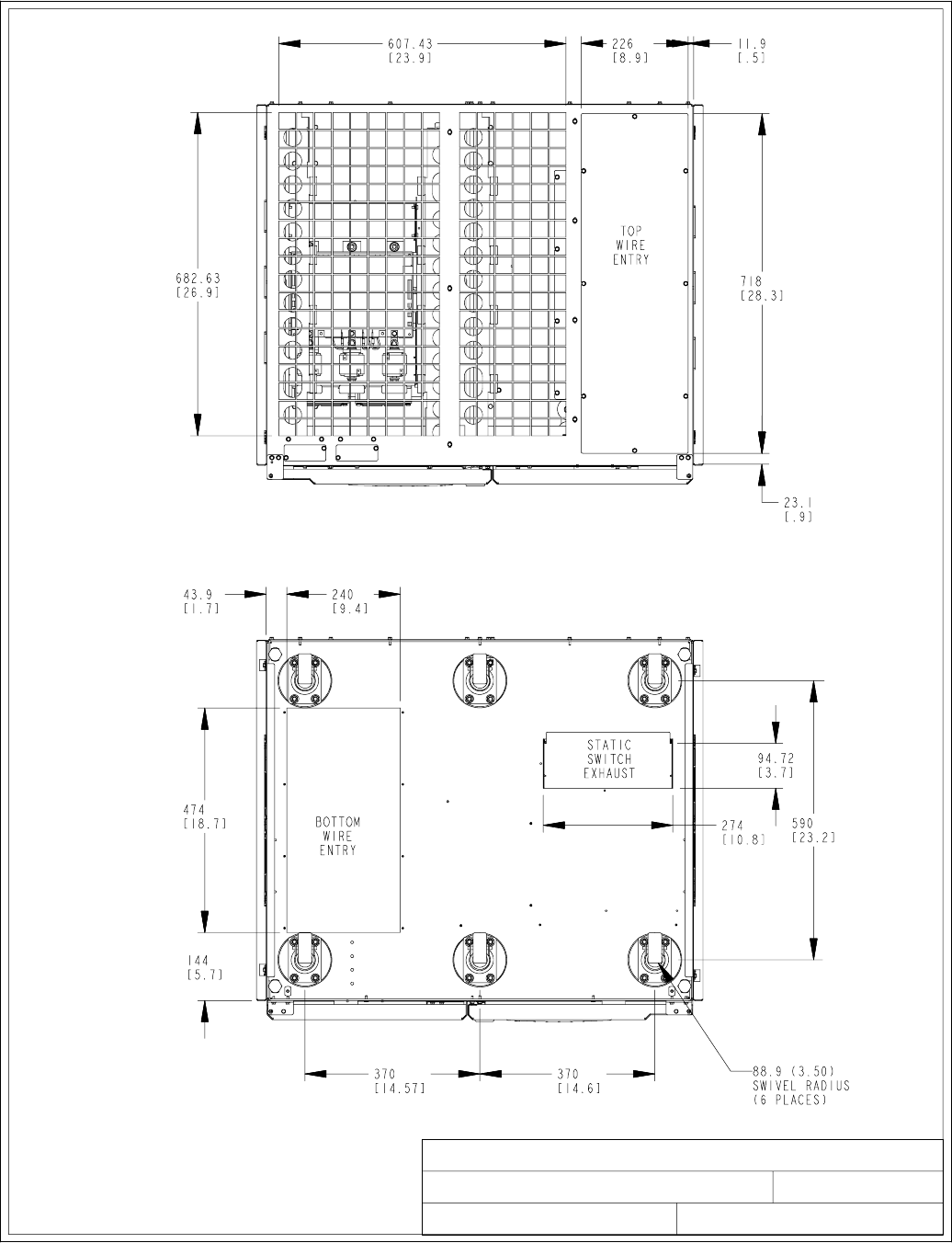
UPS CABINET DIMENSIONS
091505A
164201604---9
TOP VIEW
BOTTOM
VIEW
Dimensions are in millimeters [inches]
2of4
DESCRIPTION:
DATE:
DRAWING NO: SHEET:
REVISION:
LEFT SIDE
LEFT SIDE
RIGHT SIDE
RIGHT SIDE
FRONT
FRONT
Installation Information
A-47
EATON Powerware®9390 UPS (100–160 kVA) Installation and Operation Manual S164201604 Rev B powerware.com
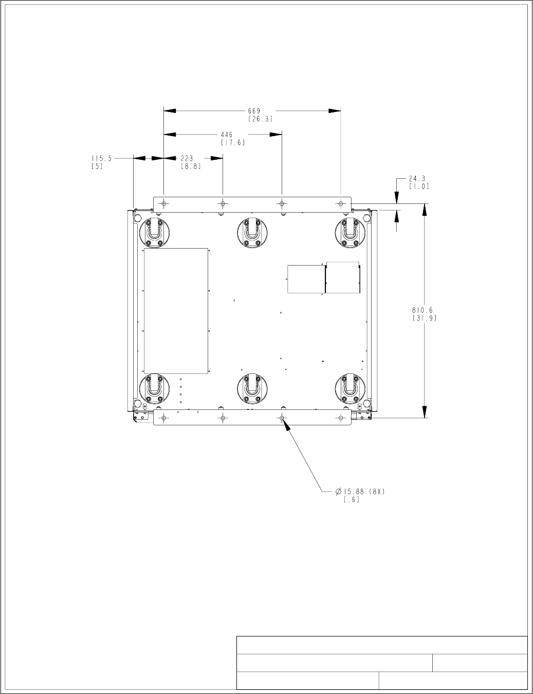
UPS CABINET DIMENSIONS
091505A
164201604---9
BOTTOM VIEW WITH OPTIONAL FLOOR MOUNTING BRACKETS
Dimensions are in millimeters [inches]
3of4
DESCRIPTION:
DATE:
DRAWING NO: SHEET:
REVISION:
LEFT SIDERIGHT SIDE
FRONT
Installation Information
A-48 EATON Powerware®9390 UPS (100–160 kVA) Installation and Operation Manual S164201604 Rev B powerware.com
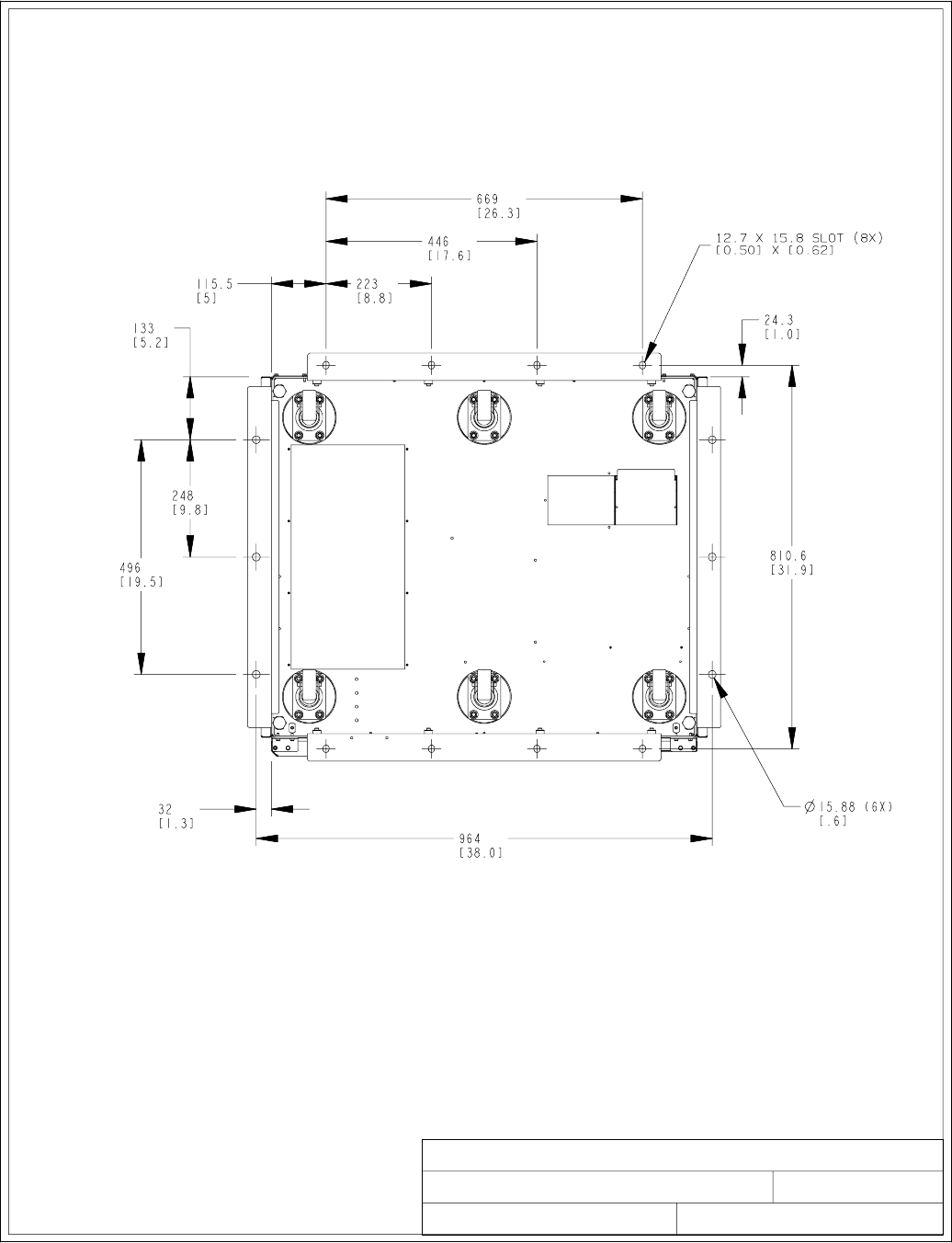
UPS CABINET DIMENSIONS
091505A
164201604---9
BOTTOM VIEW WITH OPTIONAL SEISMIC MOUNTING BRACKETS
Dimensions are in millimeters [inches]
4of4
DESCRIPTION:
DATE:
DRAWING NO: SHEET:
REVISION:
SEISMIC KIT INSTALLATION
LEFT SIDE
RIGHT SIDE
FRONT
Installation Information
A-49
EATON Powerware®9390 UPS (100–160 kVA) Installation and Operation Manual S164201604 Rev B powerware.com
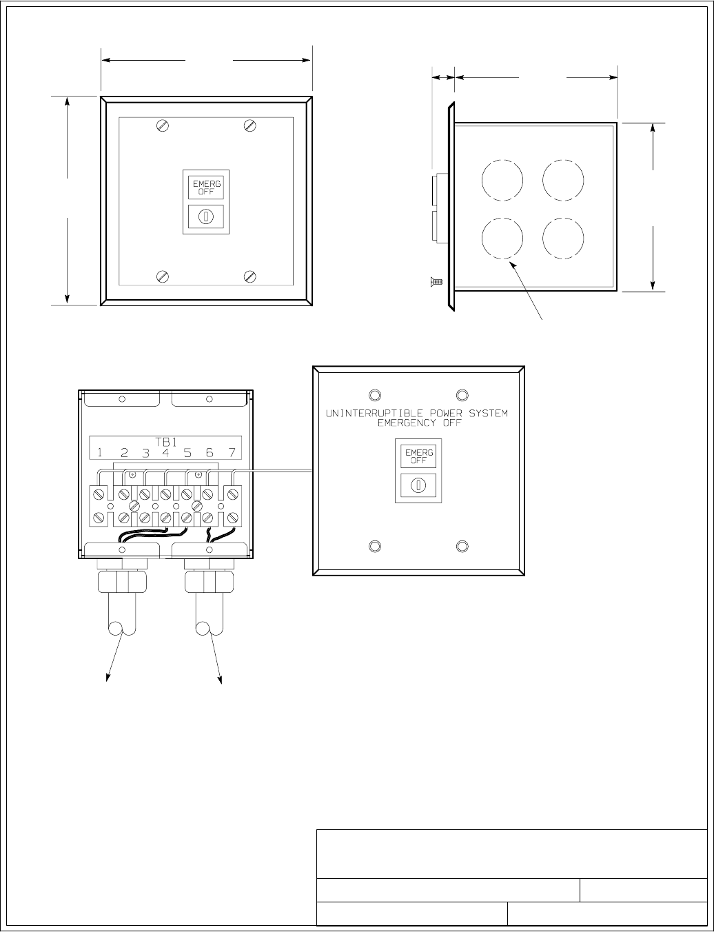
1of1
OPTIONAL POWERWARE REMOTE
EMERGENCY POWER-OFF
091505A
164201604---10
DESCRIPTION:
DATE:
DRAWING NO: SHEET:
REVISION:
114.3
(4.50)
115.8
(4.56)
11.9
(0.47)
95.3
(3.75)
SQUARE
88.9
(3.50)
1/2 in. Knockout Pattern
typ. 5 sides
TO UPS TO OTHER
EQUIPMENT
Dimensions are in millimeters [inches]
NOTE: 1. Conduit and wiring between the
Remote Emergency Power-off (REPO)
and the UPS to be supplied by the
customer.
2. Maximum distance between the
Remote EPO and the UPS not to exceed
500 feet.
3. Maximum wire size #14 AWG.
Minimum wire size #22 AWG.
Installation Information
A-50 EATON Powerware®9390 UPS (100–160 kVA) Installation and Operation Manual S164201604 Rev B powerware.com
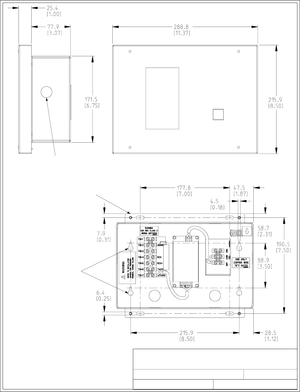
1of1
OPTIONAL REMOTE MONITOR PANEL
091505A
164201604---11
DESCRIPTION:
DATE:
DRAWING NO: SHEET:
REVISION:
KNOCKOUTS PROVIDED
ON FIVE SURFACES
FLUSH MOUNT
USE #10 PAN
HEAD SCREWS
(MOUNT WITH VENT
HOLES FACING UP)
SURFACE MOUNT
USE #10 PAN
HEAD SCREWS
(FOR HANGING)
(MOUNT WITH VENT
HOLES FACING UP)
Dimensions are in millimeters [inches]
Installation Information
A-51
EATON Powerware®9390 UPS (100–160 kVA) Installation and Operation Manual S164201604 Rev B powerware.com
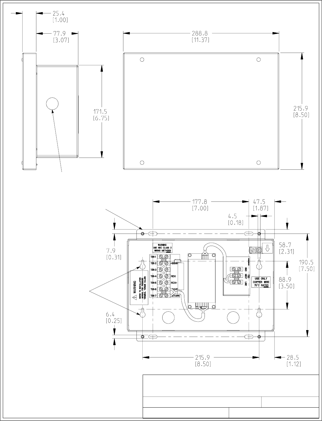
1of2
OPTIONAL RELAY INTERFACE MODULE
091505A
164201604---12
DESCRIPTION:
DATE:
DRAWING NO: SHEET:
REVISION:
KNOCKOUTS PROVIDED
ON FIVE SURFACES
FLUSH MOUNT
USE #10 PAN
HEAD SCREWS
(MOUNT WITH VENT
HOLES FACING UP)
SURFACE MOUNT
USE #10 PAN
HEAD SCREWS
(FOR HANGING)
(MOUNT WITH VENT
HOLES FACING UP)
Dimensions are in millimeters [inches]
Installation Information
A-52 EATON Powerware®9390 UPS (100–160 kVA) Installation and Operation Manual S164201604 Rev B powerware.com
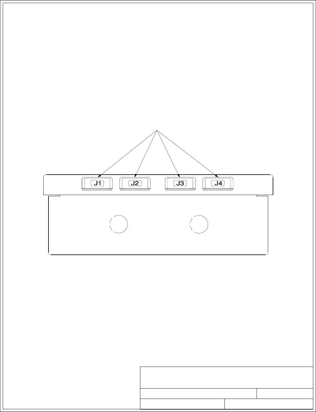
OPTIONAL RELAY INTERFACE MODULE
091505A
DESCRIPTION:
DATE:
DRAWING NO: SHEET:
REVISION:
164201604---12 2 of 2
15–PIN D–SUB CONNECTORS
Installation Information
A-53
EATON Powerware®9390 UPS (100–160 kVA) Installation and Operation Manual S164201604 Rev B powerware.com
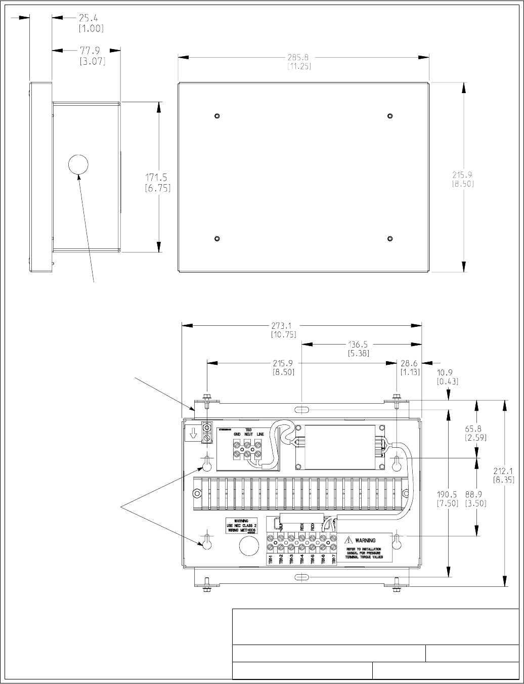
1of1
OPTIONAL SUPERVISORY CONTACT
MODULE
091505A
164201604---13
DESCRIPTION:
DATE:
DRAWING NO: SHEET:
REVISION:
KNOCKOUTS PROVIDED
ON FIVE SURFACES
FLUSH MOUNT
USE # 10 PAN
HEAD SCREWS
(MOUNT WITH VENT
HOLES FACING UP)
SURFACE MOUNT
USE # 10 PAN
HEAD SCREWS
(FOR HANGING)
(MOUNT WITH VENT
HOLES FACING UP)
Dimensions are in millimeters [inches]
Installation Information
A-54 EATON Powerware®9390 UPS (100–160 kVA) Installation and Operation Manual S164201604 Rev B powerware.com
---

W-1
EATON Powerware®9390 UPS (100–160 kVA) Installation and Operation Manual S164201604 Rev B powerware.com
Warranty
LIMITED FACTORY WARRANTY FOR THREE-PHASE POWERWARE®PRODUCTS
WARRANTOR: The warrantor for the limited warranties set forth herein is Eaton Electrical Inc., a Delaware Corporation (“Eaton”).
LIMITED WARRANTY: This limited warranty (this “Warranty”) applies only to the original end-user (the “End-User”) of the Powerware
Three-Phase UPS Products (the “Product”) and cannot be transferred. This Warranty applies even in the event that the Product is initially
sold by Eaton for resale to an End-User.
LIMITED WARRANTY PERIOD: The period covered by this Warranty for Product installed [and currently located] in the fifty (50) United
States and the District of Columbia is twelve (12) months from the date of Product start-up or eighteen (18) months from the date of
Product shipment, whichever occurs first, for parts coverage and 90 days from the date of Product start-up for labor coverage. The
period covered by this Warranty for Product installed [and currently located] outside of the fifty (50) United States and the District of
Columbia is twelve (12) months from the date of Product start-up or eighteen (18) months from the date of Product shipment,
whichever occurs first, for parts coverage.
WHAT THIS LIMITED WARRANTY COVERS: The warrantor warrants that the Powerware three-phase UPS electronics, Eaton-built
accessories, and Powerware-built battery cabinets (individually and collectively, the ”Warranted Items”) are free from defects in material
and workmanship. If, in the opinion of Eaton, a Warranted Item is defective and the defect is within the terms of this Warranty, Eaton’s
sole obligation will be to repair or replace such defective item (including by providing service, parts, and labor, as applicable), at the
option of Eaton. The Warranted Item will be repaired or replaced onsite at the End-User’s location or such other location as determined
by Eaton. Any parts that are replaced may be new or reconditioned. All parts replaced by Eaton shall become the property of Eaton.
WHAT THIS LIMITED WARRANTY DOES NOT COVER: This Warranty does not cover any defects or damages caused by: (a) failure to
properly store the Product before installation, including the ”trickle charge” of batteries no later than the date indicated on the
packaging; (b) shipping and delivery of the Product if shipping is FOB Factory; (c) neglect, accident, abuse, misuse, misapplication,
incorrect installation; (d) repair or alteration not authorized in writing by Eaton personnel or performed by an authorized Eaton
Customer Service Engineer or Agent; or (e) improper testing, operation, maintenance, adjustment, or any modification of any kind not
authorized in writing by Eaton personnel or performed by an authorized Eaton Customer Service Engineer or Agent.
This Warranty is not valid: (a) unless an authorized Eaton Customer Service Engineer (in the USA) or Agent (outside of the USA) performs
startup and commissioning of the Product; (b) if the Product is moved to a new location by someone other than an authorized Eaton
Customer Service Engineer (in the USA) or Agent (outside of the USA); or (c) if the Product’s serial numbers have been removed or are
illegible. Any Warranted Items repaired or replaced pursuant to this Warranty will be warranted for the remaining portion of the original
Warranty subject to all the terms thereof. Labor warranty is not provided for Product located outside of the fifty (50) United States or
the District of Columbia. Any equipment, parts, or materials included in the Product and not manufactured by Eaton are
warranted solely by the manufacturer of such equipment, parts, or materials and are not included as part of this Warranty.
Batteries are not warranted by Eaton.
THIS WARRANTY IS THE END-USER’S SOLE REMEDY AND IS EXPRESSLY IN LIEU OF, AND THERE ARE NO OTHER EXPRESSED OR
IMPLIED GUARANTEES OR WARRANTIES (INCLUDING ANY IMPLIED WARRANTY OF MERCHANTABILITY OR FITNESS FOR ANY
PURPOSE, WHICH ARE EXPRESSLY DISCLAIMED).
LIMITATION OF LIABILITY: In no event shall Eaton be liable for any indirect, incidental, special, or consequential damages of any kind
or type whatsoever, or based on any claim or cause of action, however denominated. Eaton shall not be responsible for failure to provide
service or parts due to causes beyond Eaton’s reasonable control. In no case will Eaton’s liability under this Warranty exceed the
replacement value of the Warranted Items.
END-USER’S OBLIGATIONS: In order to receive the benefits of this Warranty, the End-User must use the Product in a normal way,
follow the Product’s operation and maintenance manual, and protect against further damage to the Product if there is a covered defect.
OTHER LIMITATIONS: Eaton’s obligations under this Warranty are expressly conditioned upon receipt by Eaton of all payments due to
it (including interest charges, if any). During such time as Eaton hasnotreceivedpaymentofanyamountduetoitfortheProduct,in
accordance with the contract terms under which the Product is sold, Eaton shall have no obligation under this Warranty. Also during
such time, the period of this Warranty shall continue to run and the expiration of this Warranty shall not be extended upon payment of
any overdue or unpaid amounts.
COSTS NOT RELATED TO WARRANTY: The End-User shall be invoiced for, and shall pay for, all services not expressly provided for by
the terms of this Warranty, including without limitation site calls involving an inspection that determines no corrective maintenance is
required. Any costs for replacement equipment, installation, materials, freight charges, travel expenses, or labor of Eaton representatives
outside the terms of this Warranty will be borne by the End-User.
OBTAINING WARRANTY SERVICE: In the USA, call the Eaton Customer Reliability Center 7x24 at 800-843-9433. Outside of the USA,
call your local Eaton sales or service representative, or call the Eaton Customer Reliability Center in the USA at 919-870-3028. For
comments or questions about this Limited Factory Warranty, write to the Customer Quality Representative, 3301 Spring Forest Road,
Raleigh, North Carolina 27616 USA.
Warranty
W-2 EATON Powerware®9390 UPS (100–160 kVA) Installation and Operation Manual S164201604 Rev B powerware.com
This page intentionally left blank.
*164201604B*
164201604 B
