Powerwave Technologies 5JS0032 CONTINUOUS DUTY POWER AMPLIFIER User Manual Page
Powerwave Technologies Inc CONTINUOUS DUTY POWER AMPLIFIER Page
USER MANUAL

044-05040 Rev. A
INSTALLATION & SERVICE
MANUAL
MODEL K-10
CONTINUOUS DUTY
POWER AMPLIFIER
850-870 MHz
25 June 1998
Powerwave Technologies, Inc. Tel: 949-757-0530
2026 McGaw Avenue Fax: 949-757-0941
Irvine, CA 92614 Web Site: www.pwav.com

044-05040 Rev. A ii
TABLE OF CONTENTS
Par. Section 1 Page
No. General Description No.
1-1 Introduction...................................................................................................................... 1-1
1-2 General Description......................................................................................................... 1-1
1-3 Functional and Physical Specifications............................................................................ 1-1
1-4 Equipment Changes ........................................................................................................ 1-1
1-5 Ordering Information........................................................................................................ 1-2
Section 2
Installation
2-1 Introduction...................................................................................................................... 2-1
2-2 Electrical Service Recommendations .............................................................................. 2-1
2-3 Unpacking and Inspection ............................................................................................... 2-1
2-4 Installation Instructions .................................................................................................... 2-2
2-5 Amplifier Module Alarm and Control Connector .............................................................. 2-2
Section 3
Operating Instructions
3-1 Introduction...................................................................................................................... 3-1
3-2 Location and Function of Amplifier Module Control and Indicators ................................. 3-1
3-3 Initial Start-Up and Operating Procedures....................................................................... 3-3
3-4 Variable Input Switch ....................................................................................................... 3-3
Section 4
Principles of Operation
4-1 Introduction...................................................................................................................... 4-1
4-2 RF Input Signal ................................................................................................................ 4-1
4-3 RF Output Load ............................................................................................................... 4-1
4-4 Functional Description ..................................................................................................... 4-1
4-5 K10 Amplifier Module....................................................................................................... 4-3
4-5.1 Main Amplifier.................................................................................................................. 4-3
4-5.2 Loop Control .................................................................................................................... 4-3
4-5.3 Amplifier Monitoring......................................................................................................... 4-3
4-5.4 Amplifier Module Cooling................................................................................................. 4-3
4-6 Power Distribution............................................................................................................ 4-4

044-05040 Rev. A iii
TABLE OF CONTENTS (Continued)
Section 5
Maintenance
5-1 Introduction...................................................................................................................... 5-1
5-2 Periodic Maintenance ...................................................................................................... 5-1
5-3 Test Equipment Required for Test................................................................................... 5-1
5-4 Cleaning air Inlets/Outlets................................................................................................ 5-2
5-5 Performance Test............................................................................................................ 5-2
5-5.1 Amplifier Performance Test............................................................................................. 5-2
5-6 Field Replaceable Parts and Modules ............................................................................. 5-4
5-6.1 K10 Power Amplifier Module ........................................................................................... 5-4
5-6.2 Cooling Fans.................................................................................................................... 5-4
5-6.3 Fuse................................................................................................................................. 5-4
Section 6
Troubleshooting
6-1 Introduction...................................................................................................................... 6-1
6-2 Troubleshooting............................................................................................................... 6-1
6-3 Return for Service Procedure .......................................................................................... 6-2
6-3.1 Obtaining an RMA ........................................................................................................... 6-2
6-3.2 Repackaging for Shipment .............................................................................................. 6-2
LIST OF ILLUSTRATIONS
Figure Page
No. No.
1-1 Five K10 Amplifiers in Subrack........................................................................................ 1-3
2-1 Alarm and Control Connector (on Rear of K10 Module).................................................. 2-2
2-2 K10 Amplifier, Rear view ................................................................................................. 2-4
3-1 K10 Amplifier Module Control and Indicators .................................................................. 3-1
3-2 Terminal Block TB1 ......................................................................................................... 3-3
4-1 Variable Input Switch ....................................................................................................... 4-1
4-2 K10 Block Diagram.......................................................................................................... 4-2
5-1 Amplifier Test Setup diagram .......................................................................................... 5-3
LIST OF TABLES
Table Page
No. No.
1-1 Major Amplifier Components ........................................................................................... 1-2
1-2 K10 Amplifier Functional Specifications........................................................................... 1-2
1-3 Load Mismatch Tolerance ............................................................................................... 1-2
2-1 Amplifier Module Alarm and Control Connections........................................................... 2-3
3-1 Amplifier Module Control and Indicators.......................................................................... 3-2
5-1 Periodic Maintenance ...................................................................................................... 5-1
5-2 Test Equipment Required................................................................................................ 5-2
6-1 Troubleshooting............................................................................................................... 6-1

044-05040 Rev. A 1-1
GENERAL DESCRIPTION
1-1. INTRODUCTION
This manual contains information and procedures for installation, operation, and maintenance of
Powerwave’s K10 Continuous Duty Power Amplifier. The manual is organized into five sections
as follows:
Section 1. General Description
Section 2. Installation
Section 3. Operating Instructions
Section 4. Principles of Operation
Section 5. Maintenance
Section 6: Troubleshooting
1-2. GENERAL DESCRIPTION
The K10 amplifier is designed for trunking and conventional repeater applications requiring high
duty cycles. The K10 amplifier operates from RF power sources of 250 milliwatts up to 25 watts.
The amplifier consists of an input attenuator, a predriver amplifier, a microprocessor control
circuit, and two stages of amplification followed by a 7-pole distributed low-pass filter and
associated control circuitry. The K10 amplifier has a microprocessor control board that maintains
a constant output power under varying signal input and output load conditions. A system
functional block diagram of the Model K10 amplifier is contained in section 4 of this manual.
1-3. FUNCTIONAL AND PHYSICAL SPECIFICATIONS
Functional and physical specifications for the K10 amplifier are listed in tables 1-2 and 1-3.
1-4. EQUIPMENT CHANGES
Powerwave Technologies, Inc. reserves the right to make minor changes to the equipment
without notice, including but not necessarily limited to component substitution and circuitry
changes. Such changes may or may not be incorporated in this manual, although it is our
intention to keep each manual as up-to-date as possible. To that end, we ask that you, our
customer, share with us information acquired in field situations which might be of assistance to
another user. If you share it with us, we'll pass it around.
Section
1

044-05040 Rev. A 1-2
1-5. ORDERING INFORMATION
Table 1-1 following gives the part numbers and descriptions to be used when ordering either an
entire amplifier or replacement fans.
Table 1-1. Major Amplifier Components
MODEL NUMBER DESCRIPTION
K10 250 mW - 25 W 850-870
MHz Amplifier.
800-00889-001 Fan Assembly.
Table 1-2. K10 Amplifier Functional Specifications
Frequency Range: 850-870 MHz.
Operating Voltage: +28 Vdc (+1.0 Vdc)
Current Draw 9 Amperes Typical
11 Amperes Maximum
Duty Cycle: 100%
Power Input: 250 mW – 25 W.
Power Output: 100 Watts
Spurious & Harmonics: -70 dBc (Minimum)
Input/Output Impedance 50 ohms (Nominal)
Load VSWR Tolerance: See Chart
Input/Output Connector: Type 'N' Female
Vertical Mounting: 10.47"
Horizontal Mounting: 3.38"
Depth: 17.0"
Weight: 20 Pounds Nominal
Cooling Method: Fan Forced Air Over Heatsink
Operating Temp. Range: 0 °C. to +60 °C.
Storage & Transport: -10 °C. to +70 °C.
Humidity: 80% at +40 °C. (Noncondensing)
Altitude: 10,000 Feet Maximum
OPTIONS
Remote Control/Display Panel
INDICATORS
DC PWR ON, LOW OUTPUT, LOW INPUT,
HIGH INPUT, HIGH VSWR, OVER TEMP.,
L.E.D. POWER BAR METER
CONTROLS
PWR CONTROL (-10 dB)
NOTES: Manufacturer's Rated Output Power of this Equipment is for Single Carrier
Operation.
All specifications apply at +28 Vdc operating voltage.
Table 1-3. Load Mismatch Tolerance
Full Power, Sustained Operation 2:1 Maximum
Sustained Operation at Reduced Power 3:1
Microprocessor Shutdown 10:1
044-05040 Rev. A 1-3

044-05040 Rev. A 2-1
INSTALLATION
2-1. INTRODUCTION
This section contains installation recommendations, unpacking, inspection, and installation
instructions for the K10 amplifier. Carefully read all material in this section prior to equipment
unpacking or installation. Also read and review the operating procedures in Section 3 prior to
installing the equipment. It is important that the licensee perform these tasks correctly and in
good faith. If applicable, carefully read Parts 73 and 74 of the Federal Communications
Commission (FCC) rules to determine how they apply to your installation. DON'T TAKE
CHANCES WITH YOUR LICENSE.
2-2. ELECTRICAL SERVICE RECOMMENDATIONS
Powerwave Technologies recommends that proper AC line conditioning and surge suppression
be provided on the primary AC input to the +28 Vdc power source. All electrical service should be
installed in accordance with the National Electrical Code, any applicable state or local codes, and
good engineering practice. Special consideration should be given to lightning protection of all
systems in view of the vulnerability of most transmitter sites to lightning. Lightning arrestors are
recommended in the service entrance. Straight, short ground runs are recommended. The
electrical service must be well grounded.
Each amplifier system should have its own circuit breaker, so a failure in one does not shut off the
whole installation. Circuit breakers should be thermal type, capable of handling an inrush current
of 90 Amps, in a load center with a master switch.
2-3. UNPACKING AND INSPECTION
This equipment has been operated, tested and calibrated at the factory. Only in the event of
severe shocks or other mistreatment should any substantial readjustment be required. Carefully
open the container(s) and remove the amplifier module(s). Retain all packing material that can be
reassembled in the event that the unit must be returned to the factory.
CAUTION
Exercise care in handling equipment
during inspection to prevent damage
caused by rough or careless handling.
Visually inspect the amplifier module for damage that may have occurred during shipment. Check
for evidence of water damage, bent or warped chassis, loose screws or nuts, or extraneous
packing material in the connector or fans. Inspect the rear panel connector for bent connector
pins. If the equipment is damaged, a claim should be filed with the carrier once the extent of any
damage is assessed. We cannot stress too strongly the importance of IMMEDIATE careful
inspection of the equipment and the subsequent IMMEDIATE filing of the necessary claims
against the carrier if necessary. If possible, inspect the equipment in the presence of the delivery
person. If the equipment is damaged, the carrier is your first area of recourse. If the equipment is
damaged and must be returned to the factory, write or phone for a return authorization.
Powerwave may not accept returns without a return authorization. Claims for loss or damage may
not be withheld from any payment to Powerwave, nor may any payment due be withheld pending
the outcome thereof. WE CANNOT GUARANTEE THE FREIGHT CARRIER'S PERFORMANCE.
Section
2

044-05040 Rev. A 2-2
2-4. INSTALLATION INSTRUCTIONS (Refer to figures 1-1 and 2-2)
The K10 amplifier module is designed for installation in a subrack that permits access to the rear
of the subrack for connection of DC power, RF, and monitor cables.
To install the amplifier proceed as follows:
1. Install subrack in equipment rack and secure in place.
2. Install the plug-in K10 amplifier module(s) in the subrack. Tighten top and bottom
thumbscrews.
3. Connect 50-ohm antenna cable to RF OUT connector on rear of amplifier module.
4. Connect the transceiver/exciter output to RF IN connector on rear of amplifier module.
5. Connect alarm and control cable to 9-pin D-sub connector on rear of amplifier module. Refer
to paragraph 2-5 for connector definition.
WARNING
Turn off external primary DC power before
connecting DC power cables.
6. Connect positive primary power to +28V terminal and negative primary power to GND terminal
on rear of amplifier module. Tighten the power connections.
7. Check your work before applying DC voltage to the system. Make certain all connections are
tight and correct.
8. Measure primary DC input voltage. DC input voltage should be +28 Vdc ±1.0 Vdc. If the DC
input voltage is above or below the limits, call and consult Powerwave before you turn on your
amplifier system.
9. Refer to section 3 for initial turn-on and checkout procedures.
2-5. AMPLIFIER MODULE ALARM AND CONTROL CONNECTOR
The alarm and control connections on the amplifier are made through a female 9-pin D-sub
connector (figure 2-1) and are listed and described in table 2-1.
Figure 2-1. Alarm and Control Connector (on Rear of K10 Module)

044-05040 Rev. A 2-3
Table 2-1. Amplifier Module Alarm and Control Connections
PIN NUMBER FUNCTION DESCRIPTION
1 Low Input Power Indicates alarm when input drive is approximately 2.5 dB below
specified range.
2 GND System Ground
3 Over Temperature Indicates alarm if junction temperature exceeds 60 °C
4 VSWR Indicates alarm for VSWR >3:1
5 Fwd Detect Vdc Input drive range set
6 External Reset Resets microprocessor after alarm condition is set
7 DC Power Indicates alarm condition when 24 Vdc > power supply > 30 Vdc
8 RF Output Status Indicates alarm if an output transistor fails
9 Not used No connection
044-05040 Rev. A 2-4
Figure 2-2. K10 Amplifier, Rear View

044-05040 Rev. A 3-1
OPERATING INSTRUCTIONS
3-1. INTRODUCTION
This section contains operating instructions for the K10 Amplifier.
3-2. LOCATION AND FUNCTION OF AMPLIFIER MODULE CONTROL AND INDICATORS.
The location and function of the K10 amplifier module control and indicators is shown in figure 3-1
and is described in detail in table 3-1.
Figure 3-1. K10 Amplifier Module Control and Indicators
Section
3

044-05040 Rev. A 3-2
Table 3-1. Amplifier Module Control and Indicators
NO. NAME FUNCTION
1 DC PWR ON
Indicator Green LED. Continuous illumination at voltages from 26-29.9 Vdc (this
is the acceptable operating range for the K10 amplifier). At DC volt-
ages from 24-25.9 Vdc, the LED will flash and the output power will
remain at its specified level. At voltages less than 24 and greater than
30 Vdc, the K10 will shut down, and the DC POWER ON LED will
flash.
2 LOW OUTPUT
Indicator Red LED. Activates when:
1. The op amp in the automatic gain control becomes saturated at its
rails, or
2. One of the finals in the amplifier becomes faulty.
3 LOW INPUT
Indicator
(Refer to figure
3-2)
Red LED. Activates when input drive to the K10 drops by 1.5 dB from
its rated input drive. At this point, the led will flash, but the output will
remain at its rated power. Should the RF input drive drop by another
1 dB, the LED will illuminate continuously and there will be no output
from the K10 amplifier.
4 HIGH INPUT
Indicator
(Refer to figure
3-2)
Red LED. Activates when input drive to the K10 is increased by 1.5 dB
from its rated input drive. At this point, the led will flash, but the output
will remain at its rated power. Should the RF input drive increase by
another 1 dB, the LED will i
il
ll
lu
um
mi
in
na
at
te
e
c
co
on
nt
ti
in
nu
uo
ou
us
sl
ly
y and there will be no
output from the K10 amplifier.
5 HIGH VSWR
Indicator Red LED. Activates at loads greater than 3:1. At this point, the ampli-
fier output will drop by -3dB. Should the output load open (VSWR
>10:1) the indicator will still be lit and there will be no output from the
amplifier.
6 OVER TEMP
Indicator Red LED. Activates when the heatsink of the amplifier exceed 63 de-
grees Celsius. At this point, the K10 amplifier will shut down, and there
will be no output. When the amplifier has sufficiently cooled, the K10
will resume normal operation.
7 PWR CONTROL
Adjustment Allows user to reduce the power output by more than 10 dB below the
factory-set 100 watts.
8 POWER
Indicator Output LED bar level indicator. Each bar represents 10 watts of output
power.
044-05040 Rev. A 3-3
044-05040 Rev. A 3-4
3-3. INITIAL START-UP AND OPERATING PROCEDURES
To perform the initial start-up, proceed as follows:
1. Double-check to ensure that all input and output cables are properly connected.
CAUTION
Before applying power, make sure that the input and output of the
amplifier are properly terminated at 50 ohms. Do not operate the
amplifier without a load attached. Refer to table 1-2 for input power
requirements. Excessive input power may damage the amplifier
NOTE
The output coaxial cable between the amplifier and the antenna must
be 50 ohm coaxial cable. Use of any other cable will distort the output.
2. Verify that power supply measures 28 ±1 Vdc. Apply power to the amplifier(s). Do not apply
an RF signal to the amplifier system.
3. Visually check the indicators on each amplifier module, and verify the following:
a. The DC PWR ON indicator (green) on all amplifier modules should be on.
b. The LOW INPUT indicator (red) on all amplifier modules should be on.
4. Turn on external exciter/transceiver and apply RF input signals. All red LEDs should turn off
within 2.5 seconds.
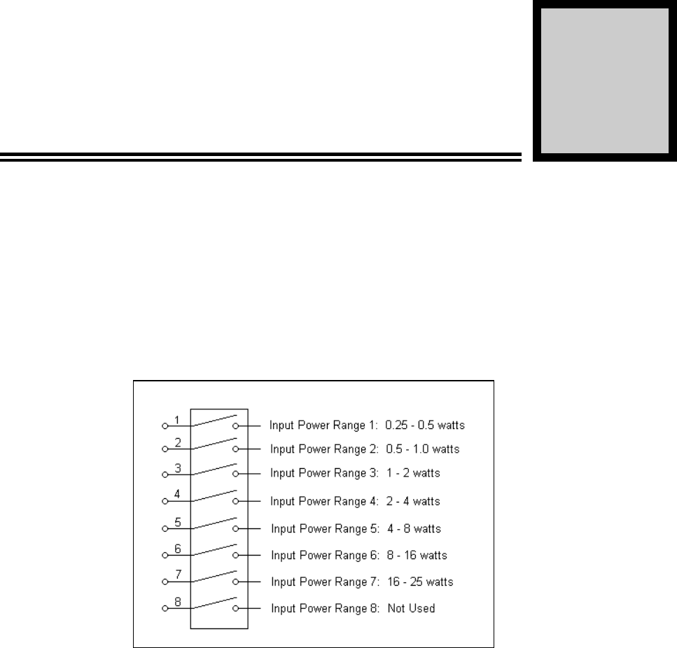
3-4. VARIABLE INPUT SWITCH
If the RF input to the K10 amplifier should change, figure 4-1 shows which DIP switch to activate
for various inputs. This should only be performed by a trained technician, and with prior approval
and instructions from Powerwave’s service department. Failure to receive prior permission to
open the amplifier could void the warranty.
1. Verify that no DC or RF is applied to the K10.
2. If necessary, remove K10 from subrack.
3. Remove the lid from the K10.
4. Locate the variable toggle switch (S1) on the 500-00800-001 driver PCB.
5. Refer to figure 4-1 for various switch settings.
044-05040 Rev. A 4-1
PRINCIPLES OF OPERATION
4-1. INTRODUCTION
This section contains a functional description of the K10 Amplifier.
4-2. RF INPUT SIGNAL
K10 amplifiers are equipped with an input variable switch that ranges from 250mW to 25W (see
figure 4-1). They have a predriver module that consists of an input attenuator pad, variable input
attenuator, and a power amplifier module that provides up to 13dB of gain. The microprocessor
uses detector circuitry to maintain a constant output level by sensing RF input, output, VSWR,
temperature, and driver/final failures. Input VSWR to the K10 should not exceed 2:1 for best
performance.
Figure 4-1. Variable Input Switch
4-3. RF OUTPUT LOAD
The load impedance should be as good as possible (2:1 or better) in the working band for good
power transfer to the load.
4-4. FUNCTIONAL DESCRIPTION
The K10 amplifier (see block diagram figure 4-2) is a linear, single channel amplifier that operates
in the frequency band from 850 MHz to 870 MHz. The amplifier specifications are listed in table
1-2. Each amplifier is a self-contained plug-in module and is functionally independent of other
amplifier modules. The amplifier modules are designed for parallel operation to achieve high
peak power output, and for redundancy in unmanned remote locations. Each amplifier in the
system can simultaneously transmit carrier frequencies, at an average total power output of 100
watts.
Section
4
044-05040 Rev. A 4-2
044-05040 Rev. A 4-3
4-5. K10 AMPLIFIER MODULE
The amplifier module has an output of 100 watts power with all harmonics suppressed to better
than -70 dBc below carrier level. The amplifier module is comprised of:
Microprocessor board/alarm monitoring
Pre-driver board/splitter
Two final gain stages
Alarm monitoring, control, and display panel
Distributed low pass filter board/ combiner board
4-5.1. MAIN AMPLIFIER
The input and output of the amplifier employ three-stage, class AB amplifiers which provide
approximately 54 dB of gain in the 20 MHz frequency band from 850 MHz to 870 MHz. The
amplifier operates on +28 Vdc, and a bias voltage of +6 Vdc, and is mounted directly on a heat
sink. The alarm logic controls the +6 Vdc bias voltage which shuts down the amplifier.
4-5.2. LOOP CONTROL
The loop control circuitry consists of a microprocessor (see paragraph 4-2), which prevents the
RF output and input power from exceeding the safe operating maximum power levels.
The RF output power from the model K10 amplifier is controlled by the microprocessor. A
coupled detector on the low-pass filter PCB monitors the final RF output level and generates a DC
voltage (VFWD) proportional to the RF output level. VFWD is fed back to the microprocessor.
The microprocessor compares this voltage to a reference voltage, and varies the output gain of
the driver module to maintain a constant 100-watt output. The microprocessor also provides
over-temperature protection for the amplifier. All RF modules in the amplifier are mounted on a
common heatsink. The modules all have temperature-sensing lCs mounted on them which
constantly monitor heat and convert it to a DC voltage. This voltage is sent to the microprocessor
which shuts down the amplifier should temperatures exceed 63 degrees Celsius. When the
amplifier has sufficiently cooled down, the microprocessor re-enables the amplifier.
The output of the driver amplifier, approximately five watts of power, is fed to a 2-way power
splitter, amplified by the two parallel final amplifier modules, then combined and fed to the 7-pole
distributed low-pass filter. The filter attenuates any spurious and harmonic signals that may have
been produced by the various gain stages, for a final RF output of 100 watts. Double shielded
Teflon cable is used for all high power RF interconnections.
4-5.3. AMPLIFIER MONITORING
In the main amplifier modules, all normal variations are automatically compensated for by the
microprocessor. However, when large variations occur beyond the adjustment range of the loop
control, a low output alarm will occur. The alarms are displayed in the front panel indicators.
Status indicators on the front panel include DC PWR ON, LOW OUTPUT, LOW INPUT, HIGH
INPUT, HIGH VSWR, and OVER-TEMP. AN RF power-level adjustment potentiometer is also
provided on the front panel. The power adjustment allows the user to reduce the power output by
more than 10 dB below the factory-set 100-watt output. An output LED bar level indicator is also
provided on the K10. Each bar represents 10 watts of output power.
4-5.4. AMPLIFIER MODULE COOLING
Although each amplifier module contains its own heat sink, It is cooled with forced air. Two fans
are used for forced air cooling and redundancy. The fans, located on the rear of the amplifier
module and operating continuous duty from applied DC, draw ambient air in through the front of
the amplifier and exhaust hot air out the rear of the module. The fans are field replaceable.
4-6. POWER DISTRIBUTION
Primary DC power for the system is provided by the host system. This system supplies each
amplifier module with +28 Vdc directly via a 15-amp fuse located on the rear panel of the
044-05040 Rev. A 4-4
amplifier. The amplifier module has a DC/DC converter that converts the +28 Vdc to +6 Vdc to
provide bias.
044-05040 Rev. A 5-1
MAINTENANCE
5-1. INTRODUCTION
This section contains periodic maintenance and performance test procedures for the K10. It also
contains a list of test equipment required to perform the identified tasks.
NOTE
Check your sales order and equipment warranty
before attempting to service or repair the unit. Do
not break the seals on equipment under warranty or
the warranty will be null and void. Do not return
equipment for warranty or repair service until proper
shipping instructions are received from the factory.
5-2. PERIODIC MAINTENANCE
Periodic maintenance requirements are listed in Table 5-1. Table 5-1 also lists the intervals at
which the tasks should be performed.
WARNING
Wear proper eye protection to avoid eye injury
when using compressed air.
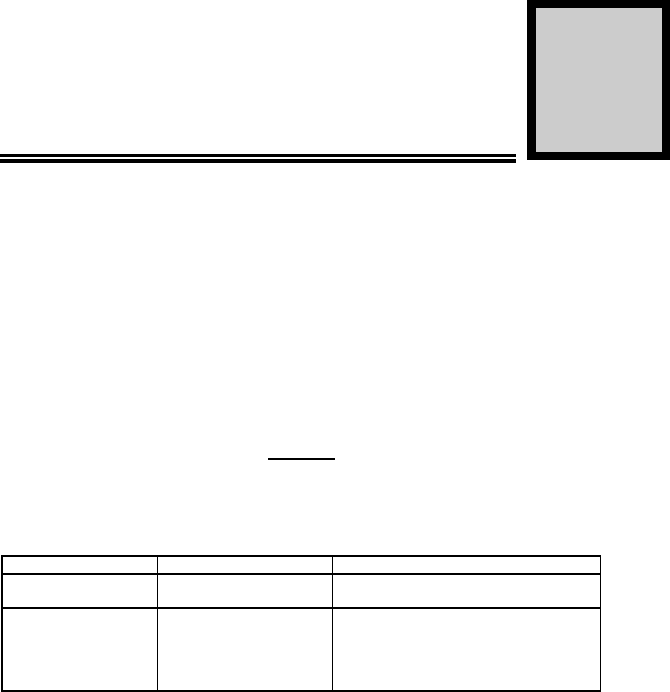
Table 5-1. Periodic Maintenance
TASK INTERVAL ACTION
Cleaning
Air Vents 30 Days Inspect and clean per paragraph 5-4
Inspection
Cables and
Connectors 12 Months Inspect signal and power cables for
frayed insulation. Check RF connectors
to be sure that they are tight.
Performance Tests 12 Months Perform annual test per paragraph 5-5.
5-3. TEST EQUIPMENT REQUIRED FOR TEST
Test equipment required to test the amplifier system is listed in Table 5-2. Equivalent test
equipment may be substituted for any item.
NOTE
All RF test equipment must be calibrated to 0.05
dB resolution. Any deviation from the nominal
attenuation must be accounted for and factored
into all output readings.
Section
5

044-05040 Rev. A 5-2
Table 5-2. Test Equipment Required
NOMENCLATURE MANUFACTURER MODEL
Signal Generator H.P. 8648B
40 dB Attenuator, 250 Watt Tenuline
DC power supply H.P 6269B
Spectrum Analyzer H.P. 8560E
Dual Directional Coupler Narda
Power Meter / Sensor H.P. 437B / 8481A
Linear Discreet Amplifier
Digital Multi-Meter Fluke 73
Current Probe
5-4. CLEANING AIR INLETS/OUTLETS
The air inlets and outlets should be cleaned every 30 days. If the equipment is operated in a
severe dust environment, they should be cleaned more often as necessary. Turn off DC power
source before removing fans. If dust and dirt are allowed to accumulate, the cooling efficiency
may be diminished. Using either compressed air or a brush with soft bristles, loosen and remove
accumulated dust and dirt from the air inlet panels.
5-5. PERFORMANCE TEST
Performance testing should be conducted every 12 months to ensure that the amplifier system
meets the operational specifications listed in table 1-2. Also verify system performance after any
amplifier module is replaced in the field. The test equipment required to perform the testing is
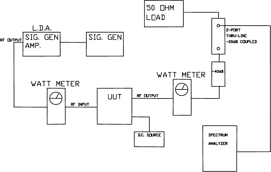
listed in table 5-2, and the test setup is shown in figure 5-1.
NOTE
The frequencies used in this test are typical for an
amplifier with a band from 850 MHz to 870 MHz.
5-5.1. AMPLIFIER PERFORMANCE TEST.
This test is applicable to a subrack equipped with one to five plug-in K10 amplifier modules.
Perform the tests applicable to your system. To perform the test, proceed as follows:
1. Connect test equipment as shown in figure 5-1.
NOTE
Do not apply any RF signals at this time.
2. Turn on DC (28 V). Turn on signal generator and set frequency to 860 MHz.
HARMONICS TEST
3. With the power amplifier set at 100 watts power output, use the spectrum analyzer and
check the frequency band from 850 MHz to 870 MHz for harmonics. Harmonics should
be -70 dBc maximum.
SPURIOUS TEST
4. With the power amplifier set at 100 watts power output, use the spectrum analyzer and
check the frequency band from 850 MHz to 870 MHz for spurious signals. Spurious
signals should be -70 dBc maximum.
044-05040 Rev. A 5-3
GAIN TEST:
5. Disconnect spectrum analyzer from test setup, and connect the power meter.
6. Apply the rated input RF drive to the K10. Verify that the unit delivers 100W out for rated
input.
Figure 5-1. Amplifier Test Setup Diagram
044-05040 Rev. A 5-4
5-6. FIELD REPLACEABLE PARTS AND MODULES
The following parts and modules can be replaced in the field on site by a qualified technician with
experience maintaining RF power amplifiers and similar equipment:
1. K10 Power Amplifier Modules
2. Cooling Fans
3. 15 Amp Fuse
5-6.1. K10 POWER AMPLIFIER MODULE
To replace a K10 module, proceed as follows:
1. Loosen two thumbscrews that secure amplifier module to subrack.
CAUTION
When removing the amplifier from the subrack, it is very
important to support the amplifier such that the rear of the
module does not suddenly drop when the guide rail disengages
from the track. A drop such as this could damage the rear of the
amplifier.
2. Use the handles on the front of the module, and with a steady even pressure, pull the
module out of chassis.
5-6.2. COOLING FANS
To replace a cooling fan, proceed as follows:
1. Remove amplifier module from subrack.
2. Loosen three screws that secure fan to amplifier module. Disconnect fan power
connector from amplifier module.
3. Install replacement fan in reverse order of steps 1 and 2 above.
5-6.3. FUSE
The K10 amplifier 28 Vdc power input line contains a single fuse as follows:
Manufacturer: Littlefuse
Manufacturer’s Number: 313015
Rating: 15 amps
Style 3AG Slo-Blo
Size: 1/4 inch diameter
1-1/4 inches long
044-05040 Rev. A 6-1
TROUBLESHOOTING
6-1 INTRODUCTION
This section contains a list of problems which users have encountered and a few suggested
actions that may correct the problem. If the suggested corrective action does not eliminate the
problem, please contact your Powerwave field representative or the factory for further instructions.
NOTE
Check your sales order and equipment warranty
before attempting to service or repair the unit. Do
not break the seals on equipment under warranty or
the warranty will be null and void. Do not return
equipment for warranty or repair service until proper
shipping instructions are received from the factory.
6-2 TROUBLESHOOTING
Refer to table 6-1 for troubleshooting suggestions.
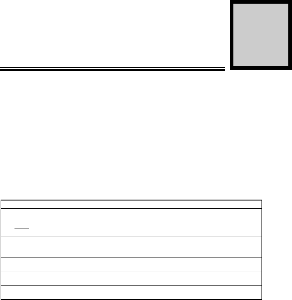
Table 6-1. Troubleshooting.
SYMPTOM SUGGESTED ACTION
Any voltage indicators (green)
are not lit or blinking
1. Check that subrack power connection is secure.
2. Check for proper power supply voltage.
3. Check fuses or circuit breakers on amplifier or subrack.
4. Verify that amplifier is fully inserted into subrack.
OVER TEMP alarm (red) is lit 1. Verify fan(s) are operating properly.
2. Check ambient temperature (not to exceed spec – see
table 1-2)
HIGH/LOW INPUT alarm
(red) is lit Verify RF input level does not exceed spec – see table 1-2
HIGH VSWR alarm (red) is lit Check output connections and cables for integrity and
tightness
LOW OUTPUT alarm (red) is
lit Contact Powerwave field representative or factory.
Section
6
044-05040 Rev. A 6-2
6-3 RETURN FOR SERVICE PROCEDURES
When returning products to Powerwave, the following procedures will ensure optimum response.
6-3.1 Obtaining an RMA
A Return Material Authorization (RMA) number must be obtained prior to returning
equipment to the factory for service. Please contact our Customer Service Department at
(949) 757-0530 to obtain this number. Failure to obtain this RMA number will result in
considerable delays in receiving repair service.
6-3.2 Repackaging for Shipment
To ensure safe shipment of the amplifier, it is recommended that the package designed
for the amplifier be used. The original packaging material is reusable. If it is not
available, contact Powerwave’s Customer Service Department for packing materials and
information.