Powerwave Technologies 5JS0045 Multicarrier PCS Power Amplifier User Manual Section 3
Powerwave Technologies Inc Multicarrier PCS Power Amplifier Section 3
UserManual.wiki
>
Powerwave Technologies
>
5JS0045 User Manual
>
User Manual Section 3
Contents
1.
Manual table of contents
2.
User Manual Section 2
3.
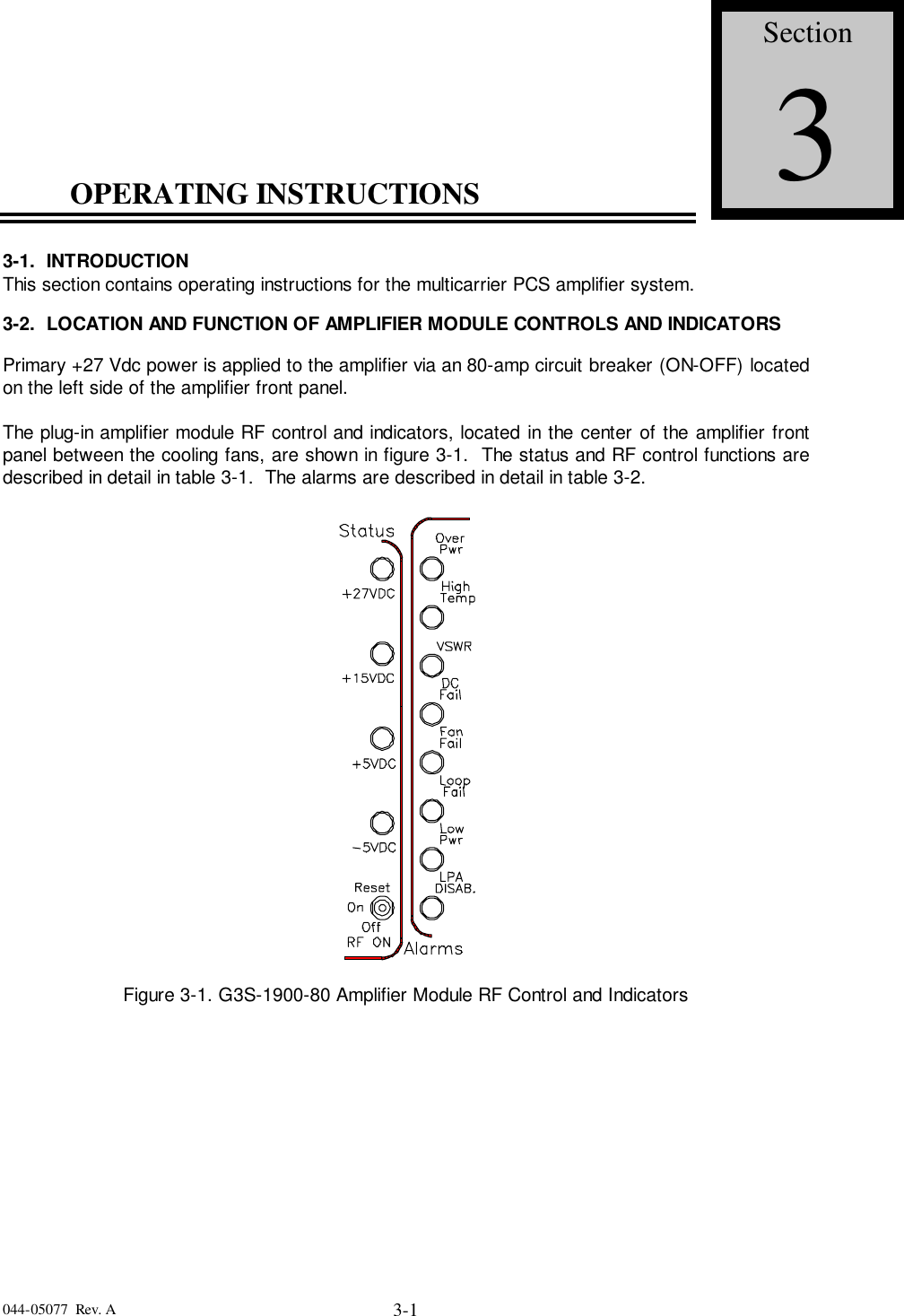
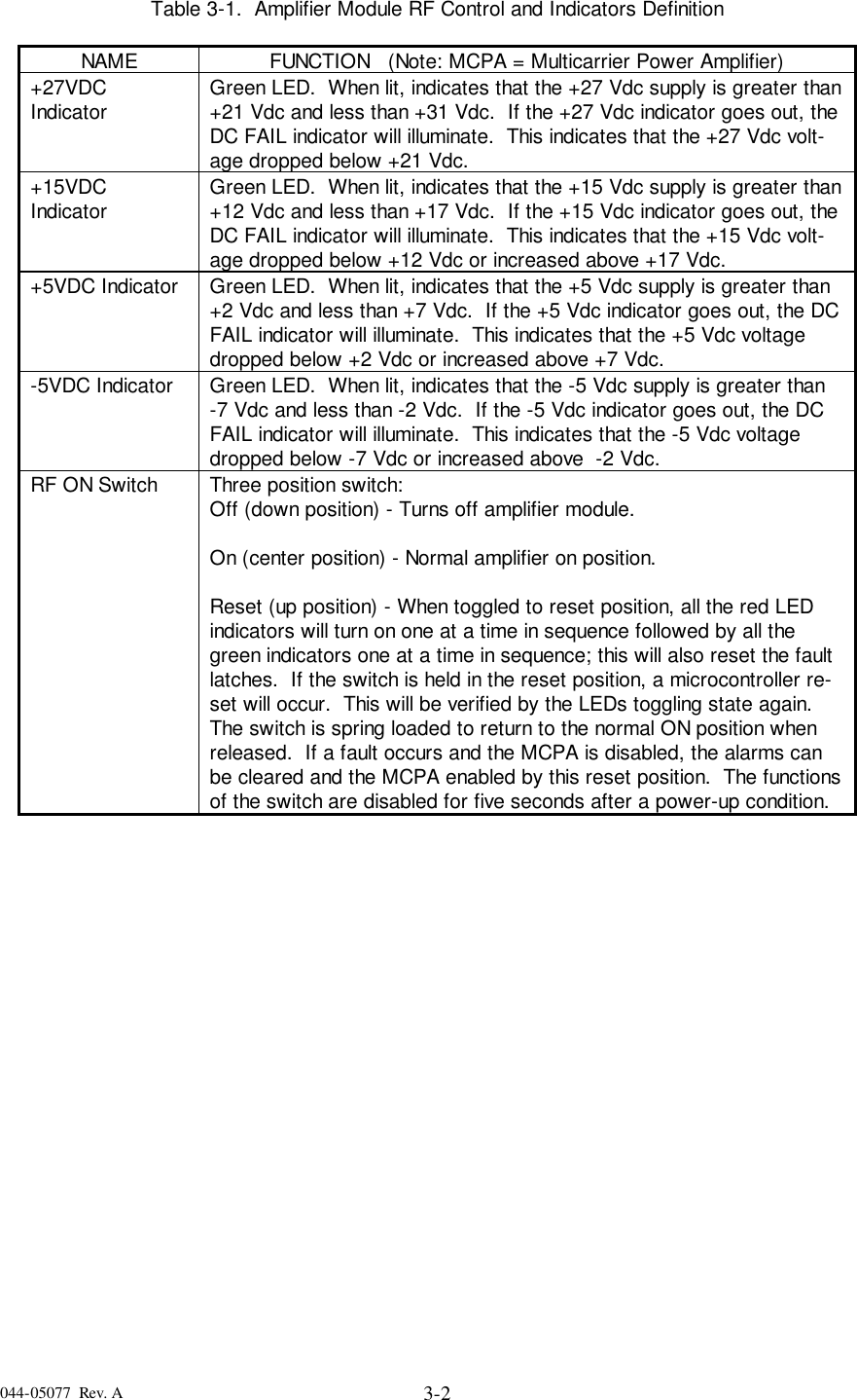
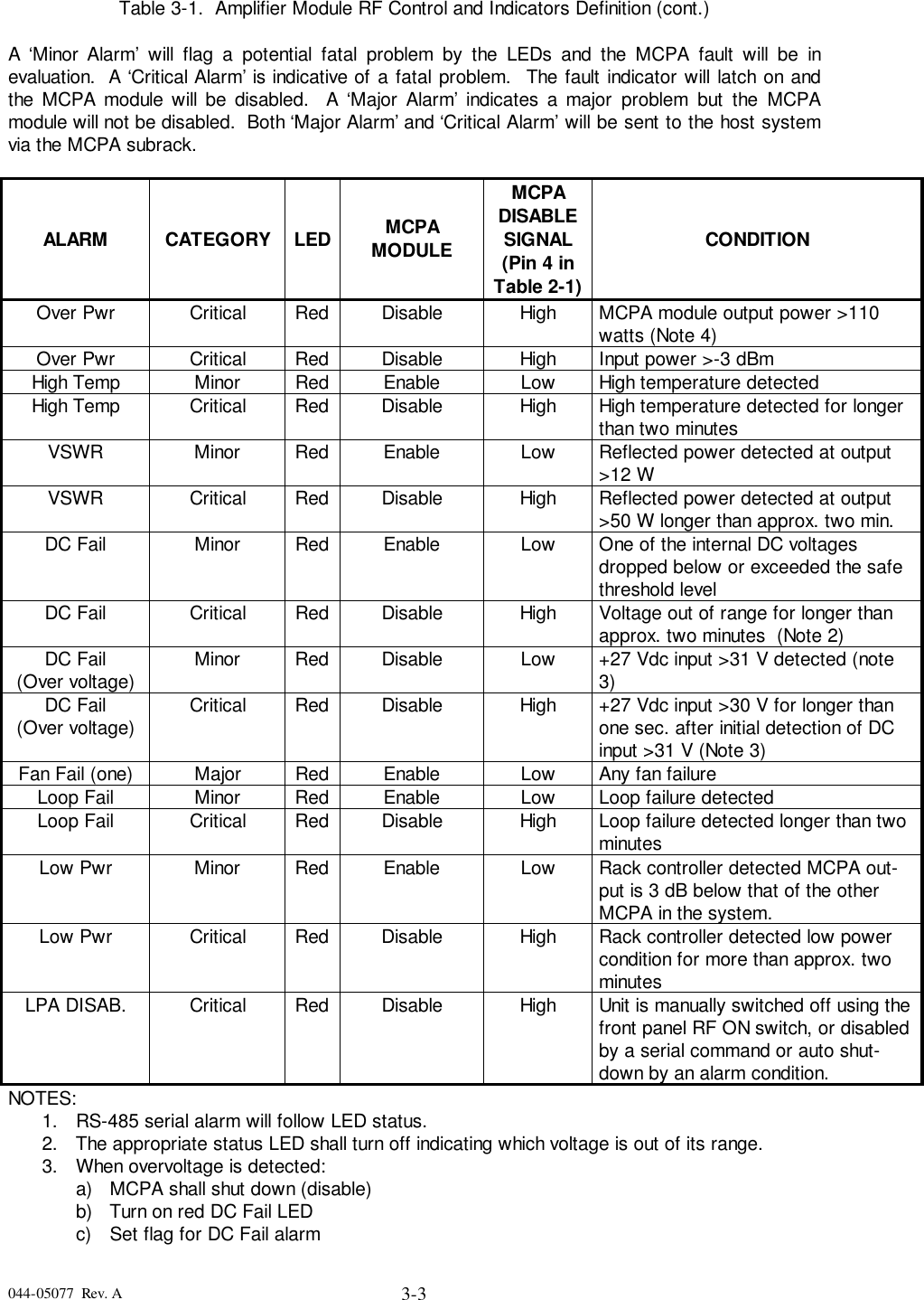
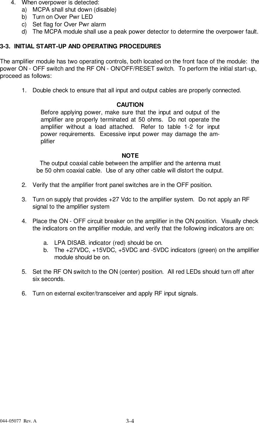
User Manual Section 3
4.
User Manual Section 4
5.
User Manual Section 6
User Manual Section 3
Navigation menu
Upload a User Manual
Namespaces
Wiki Guide
HTML
PDF
Info
Views
User Manual
Discussion / Help
Navigation