Powerwave Technologies 5JS0061 Amplifier User Manual PAF 0850 001
Powerwave Technologies Inc Amplifier PAF 0850 001
Manual

869-894 MHz
Model NTGS86AB
Single-Channel Power Amplifier
Installation & Service
Manual
Copyright Powerwave Technologies, Inc., October 2002. All rights reserved
044-05126 Rev. A October 2002

NTGS86AB Installation & Service Manual
October 2002
© 2002 Powerwave Technologies Incorporated. All rights reserved.
Powerwave Technologies, and the Powerwave logo are registered trademarks
Powerwave Technologies, Inc. reserves the right to make changes to the documentation and
equipment, including but not limited to component substitution and circuitry changes. Changes that
impact this manual may subsequently be incorporated in a later revision of this manual.
Powerwave Technologies, Inc. Tel: (714) 466-1000
1801 East St. Andrew Place (888) 797-9283
Santa Ana, CA 92705 Fax: (714) 466-5800
Web Site: www.powerwave.com
Copyright Powerwave Technologies, Inc., October 2002. All rights reserved
044-05126 Rev. A ii October 2002

NTGS86AB Installation & Service Manual
Table Of Contents
Paragraph Section 1 Page
No. General Description No.
1-1 Introduction ..................................................................................................................................................... 1-1
1-2 General Description....................................................................................................................................... 1-1
1-3 Functional and Physical Specifications.................................................................................................... 1-1
1-4 Equipment Changes ....................................................................................................................................... 1-1
Section 2
Installation
2-1 Introduction ..................................................................................................................................................... 2-1
2-2 Electrical Service Recommendations........................................................................................................ 2-1
2-3 Unpacking and Inspection............................................................................................................................ 2-1
2-4 Installation Instructions................................................................................................................................ 2-2
2-8 Molex 18-Pin Power, Alarms, & Controls Connector.............................................................................. 2-3
Section 3
Operating Instructions
3-1 Introduction ..................................................................................................................................................... 3-1
3-2 Initial Start-Up and Operating Procedures ............................................................................................... 3-1
Section 4
Principles of Operation
4-1 Introduction ..................................................................................................................................................... 4-1
4-2 RF Input Signal................................................................................................................................................ 4-1
4-3 RF Output Load ................................................................................................................................................ 4-1
4-4 Amplifier Functional Description................................................................................................................ 4-1
4-4.1 Input Amplifier and Pre-Distortion Amplifier........................................................................................... 4-1
4-4.2 Driver Amplifier .............................................................................................................................................. 4-1
4-4.2 Main Amplifier ................................................................................................................................................ 4-2
4-5 Amplifier Module Cooling ............................................................................................................................ 4-2
4-6 Power Distribution......................................................................................................................................... 4-3
Section 5
Maintenance
5-1 Introduction ..................................................................................................................................................... 5-1
5-2 Periodic Maintenance................................................................................................................................... 5-1
5-3 Amplifier Module Field Replacement ....................................................................................................... 5-1
Section 6
Troubleshooting
6-1 Introduction ..................................................................................................................................................... 6-1
6-2 Troubleshooting.............................................................................................................................................. 6-1
6-3 Return for Service Procedures .................................................................................................................... 6-1
6-3.1 Obtaining an RMA .......................................................................................................................................... 6-1
Copyright Powerwave Technologies, Inc., October 2002. All rights reserved
044-05126 Rev. A October 2002
iii

NTGS86AB Installation & Service Manual
6-3.2 Repackaging for Shipment ........................................................................................................................... 6-1
List Of Illustrations
Figure Page
No. No.
1-1 NTGS86AB Amplifier Isometric View......................................................................................................... 1-3
1-2 NTGS86AB Amplifier Top and Side Views ................................................................................................ 1-3
2-1 NTGS86AB Amplifier Front and Side Connectors .................................................................................... 2-2
2-2 Molex 18-Pin Power, Alarms, and Controls Connector ..........................................................................2-3
4-1 NTGS86AB Single-Channel Power Amplifier Block Diagram............................................................... 4-2
List Of Tables
Table Page
No. No.
1-1 NTGS86AB Single-Channel Power Amplifier Functional Specifications ........................................... 1-2
2-1 Molex 18-Pin Power, Alarms, and Controls Connector Signal Descriptions..................................... 2-3
5-1 Periodic Maintenance................................................................................................................................... 5-1
6-1 Troubleshooting.............................................................................................................................................. 6-1
Copyright Powerwave Technologies, Inc., October 2002. All rights reserved
044-05126 Rev. A October 2002
iv

NTGS86AB Installation & Service Manual
Section 1 General Description
1-1 Introduction
This manual contains information and procedures for installation, operation, and maintenance of
Powerwave’s model NTGS86AB Single-Channel Power Amplifier (SCPA) module. The manual is
organized into six sections as follows:
Section 1. General Description
Section 2. Installation
Section 3. Operating Instructions
Section 4. Principles of Operation
Section 5. Maintenance
Section 6. Troubleshooting
1-2 General Description
The NTGS86AB amplifier module is a CDMA signal source, linear, single-channel power ampli-
fier (SCPA) module that operates in the 25 MHz frequency band from 869 MHz to 894 MHz. The
amplifier output is typically 25 watts with a gain range between 41 and 45 dB. The amplifier is de-
signed to be mounted in an enclosure with EMI containment. Its flat base plate allows for mount-
ing on a flat thermal-absorbing surface to provide adequate heat dissipation.
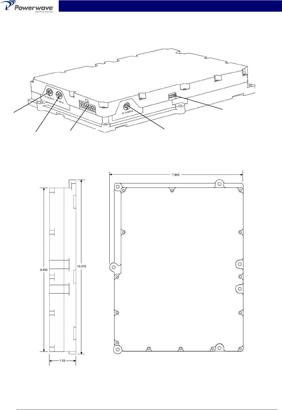
As shown in figure 1-1, each amplifier module has an RF input, RF output, and RF sample con-
nectors, as well as an 18-pin power, alarm, and control interface connector that allows the host
system to provide power and monitor the amplifier module performance. Primary power for the
amplifier is +26 Vdc.
Physical dimensions of the amplifier module are shown in figure 1-2.
1-3 Functional & Physical Specifications
Functional and physical specifications for the amplifier are listed in table 1-1.
1-4 Equipment Changes
Powerwave Technologies, Inc. reserves the right to make minor changes to the equipment, in-
cluding but not necessarily limited to component substitution and circuitry changes. Changes that
impact this manual may subsequently be incorporated in a later revision of this manual.
Copyright Powerwave Technologies, Inc., October 2002. All rights reserved
044-05126 Rev. A 1-1 October 2002

NTGS86AB Installation & Service Manual
Table 1-1 NTGS86AB Single Channel Power Amplifier Functional Specifications
Frequency Range 869 - 894 MHz (25 MHz Bandwidth)
Maximum Average Input Power 13 dBm without damage; 0 dBm typical @ rated Pout
Continuous Average Output Power 25 Watts (44 dBm)
Frequency Offset Requirement Meas. Bandwidth
750 kHz -46 dBc 30 kHz
1.5 MHz -14dBm 37.5 kHz
1.98 MHz -61 dBc 30 kHz
4 MHz -14 dBm 100 kHz
Spurious Emissions @ Maximum
Rated Output Power
(25 W/44 dBm)
Outside Tx Band -14 dBm 30 kHz
Maximum RF Gain 45 dB
Gain Flatness ± 0.15 dB for any 2-MHz band within operating ranges.
Output Protection Mismatch Protected
Input Port Return Loss VSWR 2:1 Maximum
Out of Band Spurious Less than -13 dBm/30 kHz (see above)
DC Input Power +26 ± 0.5 Vdc, 260 mV p-p maximum ripple, ≤350 watts
6 Amps typical, 13 Amps maximum
Operating Temperature Range -40 °C to +50 °C, Ambient
Operating Humidity 5% - 95% Relative Humidity (Non-condensing)
Storage Humidity 5% - 95% Relative Humidity (Non-condensing)
Interface Connectors:
RF Input SMA Female
RF Output SMA Female
RF Sample SMA Female
Power Supply, alarm, and Control
Interface
18-Pin, Molex, Female
Test 4-Pin
Weight 8 lbs
Dimensions (inches) 7.865 (W) x 10.275 (D) x 1.55 (H)
*The base station reports the center frequency of the desired operating band to the amplifier and
the amplifier adjusts the bandwidth window accordingly, between the upper and lower limits of
the frequency range.
Copyright Powerwave Technologies, Inc., October 2002. All rights reserved
044-05126 Rev. A 1-2 October 2002
NTGS86AB Installation & Service Manual
Power, Alarm
and Control
Interface
RF
Output
RF
In
p
ut
RF
Sample
Test
(RS485)
Figure 1-1. NTGS86AB Amplifier Isometric View
Figure 1-2. NTGS86AB Amplifier Top and Side Views with Dimensions
Copyright Powerwave Technologies, Inc., October 2002. All rights reserved
044-05126 Rev. A 1-3 October 2002

NTGS86AB Installation & Service Manual
Section 2 Installation
2-1 Introduction
This section contains unpacking, inspection, and installation instructions and recommendations
for the Model NTGA86AB Single-Channel Power Amplifier module. Carefully read all material in
this section prior to equipment unpacking or installation. Also read and review the operating pro-
cedures in section 3 prior to installing the equipment. It is important that the licensee perform
these tasks correctly and in good faith. If applicable, carefully read the appropriate parts of the
Federal Communications Commission (FCC) rules to determine how they apply to your installa-
tion. DON'T TAKE CHANCES WITH YOUR LICENSE.
2-2 Electrical Service Recommendations
Powerwave Technologies recommends that proper AC line conditioning and surge suppression
be provided on the primary AC input to the +26 Vdc power source. All electrical service should be
installed in accordance with the National Electrical Code, any applicable state or local codes, and
good engineering practice. Special consideration should be given to lightning protection of all
systems in view of the vulnerability of most transmitter sites to lightning. Lightning arrestors are
recommended in the service entrance. Straight, short ground runs are recommended. The elec-
trical service must be well grounded.
Each amplifier system should have its own circuit breaker, so a failure in one does not shut off
the whole installation. Circuit breakers should be thermal type, capable of handling the maximum
anticipated inrush current, in a load center with a master switch.
2-3 Unpacking & Inspection
This equipment has been operated, tested and calibrated at the factory. Carefully open the con-
tainer(s) and remove the amplifier module(s). Retain all packing material that can be reassem-
bled in the event that the unit must be returned to the factory.
CAUTION
Exercise care in handling equipment during inspection to prevent damage caused by
rough or careless handling.
Visually inspect the amplifier module for damage that may have occurred during shipment. Check
for evidence of water damage, bent or warped chassis, loose screws or nuts, or extraneous pack-
ing material in the connector. If the equipment is damaged, a claim should be filed with the carrier
once the extent of any damage is assessed. We cannot stress too strongly the importance of
IMMEDIATE careful inspection of the equipment and the subsequent IMMEDIATE filing of the
necessary claims against the carrier if necessary. If possible, inspect the equipment in the pres-
ence of the delivery person. If the equipment is damaged, the carrier is your first area of re-
course. If the equipment is damaged and must be returned to the factory, write or phone for a
return authorization. Powerwave may not accept returns without a return authorization. Claims for
loss or damage may not be withheld from any payment to Powerwave, nor may any payment due
be withheld pending the outcome thereof. WE CANNOT GUARANTEE THE FREIGHT CAR-
RIER'S PERFORMANCE
Copyright Powerwave Technologies, Inc., October 2002. All rights reserved
044-05126 Rev. A 2-1 October 2002
NTGS86AB Installation & Service Manual
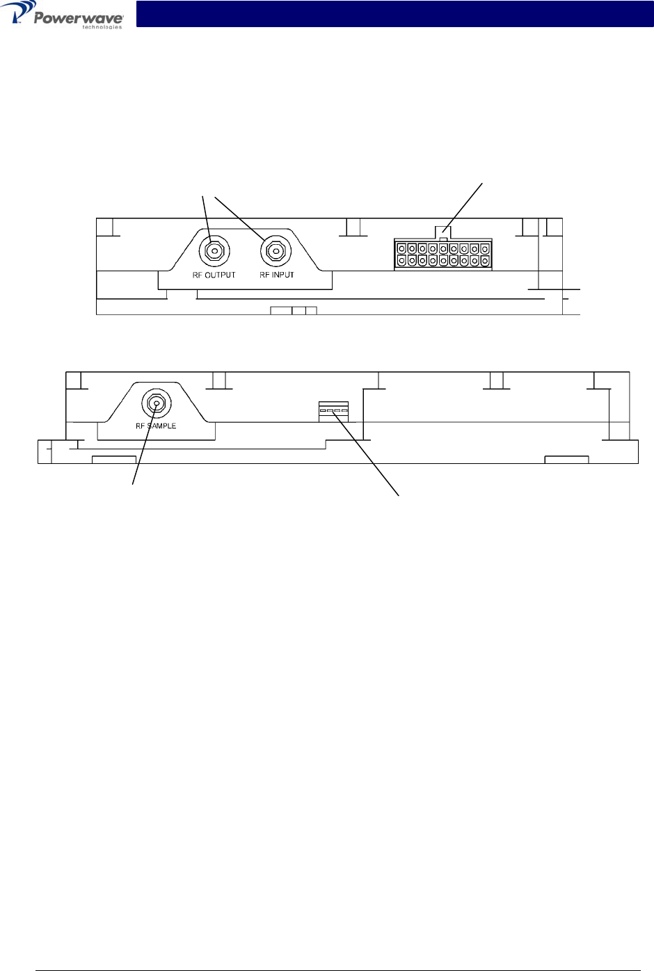
2-4 Installation Instructions (Refer to figure 1-1)
The NTGS86AB amplifier module is designed for installation on a heatsink that permits access to
the module for connection of the RF cables and to the 18-pin power, alarms, and control connec-
tor.
To install the amplifier proceed as follows:
Power, alarms, and
control interface
RF interface
Front
Figure 2-1 NTGS86AB Amplifier Front and Side Connectors
True RMS
coupler output
Side Test
connector
1. Install amplifier on heatsink with thermally conductive material inserted between amplifier
module and heatsink, and secure in place with appropriate mounting screws. See figure 1-2.
2. Connect the antenna cable to RF OUTPUT female SMA connector.
3. Connect the transceiver output cable to RF INPUT female SMA connector.
WARNING
Turn external primary DC power off before connecting any cables.
4. Connect power, alarm, and control cable to matching 18-pin Molex connector located on the
front of the amplifier as shown in figure 2-1. Refer to figure 2-2 and table 2-1 for the 18-pin
Molex connector pin orientation and a list of related signal definitions.
5. Connect to the RF SAMPLE output.
6. Check your work before applying DC voltage to the system. Make certain all connections are
tight and correct.
7. Measure primary DC input voltage for +26 ±0.5 Vdc. If the DC input voltage is above or be-
low the limits, call and consult Powerwave before you turn on your amplifier system.
8. Refer to section 3 for initial turn-on and checkout procedures.
Copyright Powerwave Technologies, Inc., October 2002. All rights reserved
044-05126 Rev. A 2-2 October 2002
NTGS86AB Installation & Service Manual
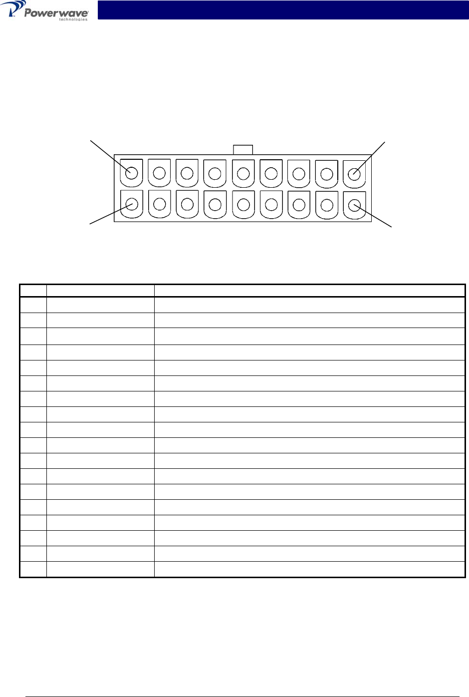
2-5 Molex 18-Pin Power, Alarms, and Controls Connector
The power, alarms, and controls connections for the amplifier are made through the 18-pin Molex
connector shown in figure 2-2. The signals for each connector pin are listed and described in ta-
ble 2-1.
View looking into front of amplifier
Pin 18 Pin 10
Pin 9 Pin 1
Figure 2-2 Molex 18-Pin Power, Alarms, and Controls Connector
Table 2-1 Molex 18-Pin Power, Alarms, and Controls Connector Signal Descriptions
Pin Signal Description
1 TEMP_OUT 0-4.7 V temperature output
2 REV_PWR 0-4.7 V Reverse power detection
3 FWR_PWR 0-4.7 V forward power detection
4 GND GND
5 N/C N/C
6 ANX(-) - Anxiety output (RS-422 level)
7 GND GND
8 GND GND
9 GND GND
10 ANX(+) + Anxiety output (RS-422 level)
11 ENABLE(+) + Enable input (RS-422 level)
12 ENABLE(-) - Enable input (RS-422 level)
13 ALARM(+) + Alarm output (RS-422 level)
14 ALARM(-) - Alarm output (RS-422 level)
15 VDD +26 VDC
16 VDD +26 VDC
17 VDD +26 VDC
18 VDD +26 VDC
Copyright Powerwave Technologies, Inc., October 2002. All rights reserved
044-05126 Rev. A 2-3 October 2002

NTGS86ABInstallation & Service Manual
Section 3 Operating Instructions
3-1 Introduction
This section contains operating instructions for the NTGS86AB Single-Carrier Cellular Power
Amplifier module.
3-2 Initial Start-Up & Operating Procedures
There are no operating controls or indicators on the NTGS86AB amplifier module. To perform the
initial start-up, proceed as follows:
1. Verify that all input and output cables are properly connected per section 2.
CAUTION
Before applying power, make sure that the input and output of the amplifier are prop-
erly terminated at 50 ohms. Do not operate the amplifier without a load attached. Re-
fer to table 1-1 for input power requirements. Excessive input power may damage the
amplifier.
NOTE
The output coaxial cable between the amplifier and the antenna must be 50 ohm co-
axial cable. Use of any other cable will distort the output.
2. Turn on supply that provides +26 Vdc to the amplifier system.
3. Turn on external exciter/transceiver and apply RF input signals.
Copyright Powerwave Technologies, Inc., October 2002. All rights reserved
044-05126 Rev. A 3-1 October 2002

NTGS86AB Installation & Service Manual
Section 4 Principles of Operation
4-1 Introduction
This section contains a functional description of the NTGS86AB Single-Carrier Cellular Power
Amplifier module.
4-2 RF Input Signal
The maximum input power should not exceed the limits specified in table 1-1.
4-3 RF Output Load
The load impedance should be as good as possible (1.5:1 or better) in the working band for good
power transfer to the load.
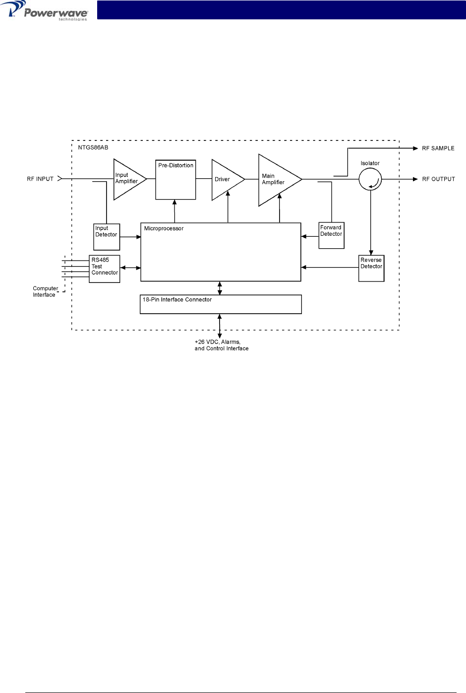
4-4 Amplifier Functional Description
The NTGS86AB amplifier (figures 1-1 and 4-1) is a linear, single-channel power amplifier that
operates in the 25 MHz frequency band from 869 MHz to 894. The amplifier produces a typical
output power of 25 watts (44 dBm). Each amplifier in a system is a self-contained module and is
functionally independent of any other amplifier modules. Each amplifier module has alarms that
monitor the amplifiers performance. If a failure or fault occurs in an amplifier module, it is trans-
mitted to the host system via an RS-422 interface.
The amplifier is compliant to the requirements of FCC Part 24 with respect to spurious emissions
(see table 1-1). Constant gain is maintained by continuously comparing active paths with passive
references, and correcting for small variations through the RF feedback controls. All gain varia-
tions, for example those due to temperature, are reduced to the passive reference variations. The
amplifier module is comprised of:
• Input amplifier
• Pre-distortion amplifier
• Driver amplifier
• Main amplifier
• Isolator
4-4.1 Input Amplifier and Predistortion Amplifier
RF is fed to the input amplifier then to the predistortion amplifier where the input signal is dis-
torted such that it linearizes the output of the main amplifier. All the predistortion voltages and
loop voltages are controlled by a microprocessor.
4-4.2 Driver Amplifier
The driver amplifier is a class AB amplifier. The amplifier operates on +26 Vdc with bias voltage
controlled by the microprocessor.
Copyright Powerwave Technologies, Inc., October 2002. All rights reserved
044-05126 Rev. A 4-1 October 2002
NTGS86AB Installation & Service Manual
4-4.3 Main Amplifier
The main amplifier is a class AB amplification stage for maximum efficiency. The RF output signal
from the main amplifier is then applied to an isolator. The amplifier power performance is moni-
tored by the microprocessor via the forward and reverse detectors. The final output power is typi-
cally 44 dBm. The amplifier operates on +26 Vdc with gate bias voltages controlled by the micro-
processor.
Figure 4-1 NTGS86AB Single-Channel Power Amplifier Functional Block Diagram
4-5 Amplifier Module Cooling
Each amplifier module is contained within a thermally conductive chassis which, when properly
mounted on an adequate thermal surface, will provide sufficient cooling to maintain the amplifier
within the specified operating temperature range.
4-6 Power Distribution
Primary DC power for the amplifier is provided by the host system. The amplifier generates all the
required voltages internally from the main source.
Copyright Powerwave Technologies, Inc., October 2002. All rights reserved
044-05126 Rev. A 4-2 October 2002
NTGS86AB Installation & Service Manual
Section 5 Maintenance
5-1 Introduction
This section contains periodic maintenance and performance test procedures for NTGS86AB
Single-Carrier Cellular Power Amplifier module.
NOTE
Check your sales order and equipment warranty before attempting to service or re-
pair the unit. Do not break the seals on equipment under warranty or the warranty will
be null and void. Do not return equipment for warranty or repair service until proper
shipping instructions are received from the factory.
5-2 Periodic Maintenance
Periodic maintenance requirements are listed in table 5-1. Table 5-1 also lists the intervals at
which the tasks should be performed.
Table 5-1 Periodic Maintenance
Task Interval Action
Inspection:
Cables and Connectors 12 Months Inspect signal and power cables for frayed insula-
tion. Check RF connectors to ensure they are tight.
Performance Tests No periodic maintenance is necessary beyond that
recommended by the base station manufacturer.
5-3 Amplifier Module Field Replacement
The NTGS86AB power amplifier module can be replaced in the field on site by a qualified techni-
cian with adequate ESD protection and experience maintaining RF power amplifiers and similar
equipment.
To replace a power amplifier module, proceed as follows:
1. Turn off the +26 Vdc power source to that specific amplifier module.
2. Disconnect the RF INPUT, RF OUTPUT, RF SAMPLE, and 18-pin Molex connectors.
3. Remove seven (7) screws that secure the amplifier module to the heat sink.
4. Carefully remove the amplifier module from the heat sink.
5. Remove any remaining Thermstrate from the heat sink. Use alcohol or other recommended
cleaning agent to achieve a clean heat sink mounting surface.
NOTE
Failure to completely remove old thermal grease, or the introduction of too much ther-
mal grease will dramatically alter the thermal transfer process between the amplifier
module and the heatsink.
6. Add Thermstrate thermal interface pad to surface of replacement amplifier, that mates with
heatsink. Use just enough Thermstrate to be evenly visible on the mounting surface.
7. Install replacement in reverse order of steps 1 through 4 above.
Copyright Powerwave Technologies, Inc., October 2002. All rights reserved
044-05126 Rev. A 5-1 October 2002

NTGS86AB Installation & Service Manual
Section 6 Troubleshooting
6-1 Introduction
This section contains a list of problems and a few suggested actions that may correct the prob-
lem. If the suggested corrective action does not eliminate the problem, please contact your
Powerwave field representative or the factory for further instructions.
NOTE
Check your sales order and equipment warranty before attempting to service or re-
pair the unit. Do not break the seals on equipment under warranty or the warranty will
be null and void. Do not return equipment for warranty or repair service until proper
shipping instructions are received from the factory.
6-2 Troubleshooting
Table 6-1 lists general guidelines established to aid Field Engineers or Cell Site Technicians in
the proper method of Powerwave equipment fault resolution by fault mode.
Table 6-1 Troubleshooting
Symptom Suggested Action
SCPA Inoperative Check for proper power supply voltage.
SCPA Not Enabled Verify ENABLE(+) line is high.
Alarm Output is (RS-422) High Verify input RF is within specified power and frequency limits
6-3 Return For Service Procedures
When returning products to Powerwave, the following procedures will ensure optimum response.
6-3.1 Obtaining An RMA
A Return Material Authorization (RMA) number must be obtained prior to returning equipment to
the factory for service. Please contact our Repair Department at (888) 797-9283 or (714) 466-
1000 to obtain this number, or FAX your request to (714) 466-5816. Failure to obtain this RMA
number may result in delays in receiving repair service.
6-3.2 Repackaging For Shipment
To ensure safe shipment of the amplifier, it is recommended that the package designed for the
amplifier be used. The original packaging material is reusable. If it is not available, contact
Powerwave’s Customer Service Department for packing materials and information.
Copyright Powerwave Technologies, Inc., October 2002. All rights reserved
044-05126 Rev. A 6-1 October 2002