Powerwave Technologies 5JS0068 Power Amplifier User Manual I GENERAL DESCRIPTION
Powerwave Technologies Inc Power Amplifier I GENERAL DESCRIPTION
Users Manual

1930-1990 MHz
Installation & Service Manual
G3L-1929- Multi-Carrier Power Amplifier
Copyright Powerwave Technologies, Inc., May 2003. All rights reserved
044-05138 Rev. A May 2003
Preliminary

G3L-1929- Installation & Service Manual
May 2003
© 2003 Powerwave Technologies Incorporated. All rights reserved.
Powerwave Technologies, and the Powerwave logo are registered trademarks
Powerwave Technologies, Inc. reserves the right to make changes to the documentation and
equipment, including but not limited to component substitution and circuitry changes. Changes
that impact this manual may subsequently be incorporated in a later revision of this manual.
Powerwave Technologies, Inc. Tel: (714) 466-1000
1801 E. St. Andrew Place (800) 473-1720
Santa Ana, CA 92705 Fax: (714) 466-5800
Web Site: www.powerwave.com
Copyright Powerwave Technologies, Inc., May 2003. All rights reserved
044-05138 Rev. A ii May 2003
G3L-1929- Installation and Service Manual
Section 1. General Description
1-1 Introduction
This manual contains information and procedures for the installation and operation of Powerwave
Technologies, Inc.’s G3L-1929-120 Multi-Carrier Power Amplifier (MCPA). This manual is organ-
ized into the following sections:
Section 1 General Description
Section 2 Installation
Section 3 Operating Instructions
Section 4 Principles of Operation
Section 5 Maintenance
Section 6 Troubleshooting
1-2 General Description
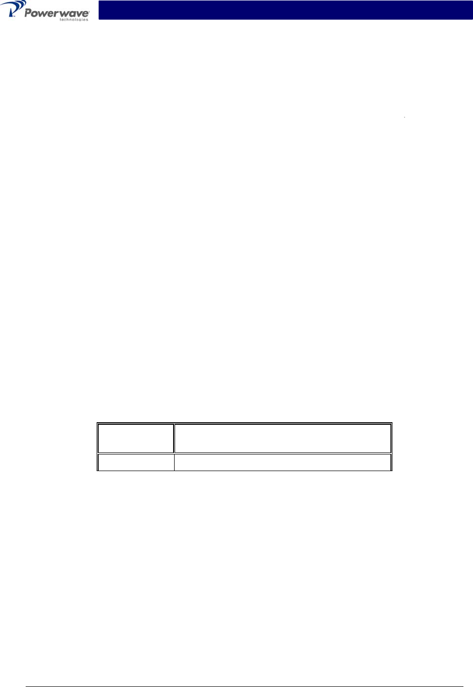
The G3L-1929-120 Power Amplifier shown in figures 1-1 through 1-6, operates in the 60 MHz fre-
quency band from 1930 MHz to 1990 MHz with channel spacing of 12.5 kHz. The amplifier provides
a typical gain of 60 dB to produce a typical output of 60 Watts (47.8 dBm). The G3L-1929-120 am-
plifier generates approximately 2300 BTUs of heat at full power. The amplifiers are modular in
design, and ideally suited for use in GSM base stations.
1-3 Ordering Information
Table 1-1 lists major system component numbers and descriptions for use in ordering booster
amplifiers or components.
Table 1-1 Major System Components
Component
Number
Description
G3L-1929-120 120-Watt Amplifier, +27 VDC
1-4 Functional and Physical Specifications
Electrical, mechanical, and environmental specifications for the G3L-1929-75 amplifier are listed
in tables 1-2, 1-3, and 1-4 respectively.
1-5 Equipment Changes
Powerwave Technologies, Inc. reserves the right to make minor changes to the equipment, in-
cluding but not limited to component substitution and circuitry changes. Changes that impact this
manual may be incorporated in a later revision of the manual.
Copyright Powerwave Technologies, Inc., May 2003. All rights reserved
044-05138 Rev. A 1-1 May 2003

G3L-1929- Installation and Service Manual
Table 1-2 G3L-1929-75 Amplifier Electrical Specifications
Frequency Range 1930 - 1990 MHz
Channel Spacing 12.5 KHz
Output Power: +50.8 dBm (120 Watts)
Input Power -10.0 dBm max.
RF Gain +60 dB ±1.0 dB @ +27Vdc, 25° C
RF Gain Flatness over the
operating frequency range ±0.1 dB over any 1.25 MHz (over the frequency range).
Gain Flatness: ±0.5 dB (1930 MHz – 1990 MHz)
Normal Operating Voltage +27 Vdc ±1V Nominal (±5%) 1Vpp ripple (100-120 Hz) max.
Current Consumption: 27.5 Amps @ 27 Vdc, 25 °C, Prf = 60 Watts average
32 Amps @ 27 Vdc, 25 °C, Prf = 75 Watts maximum
Abnormal Operating Voltage +21 Vdc to below +26 Vdc. Above +28 Vdc to +29 Vdc.
RF Gain variation by Temp &
Voltage +1dB; 0 to 50°C
Gain Variation Over Dynamic
Range ±0.5 dB max./20 dB for 0 to -20 dB rated power output
Intermodulation Distortion
In-Band Spurious
-65 dBc min. (Main signal power to Spurious @ (12.5 kHz)
-55 dBc min @ +23 to +24 Vdc
Input/Output VSWR. 1.5: 1 max @ 65° C
Load Stability Infinite VSWR. all phases
Output Isolation 20 dB min.
Copyright Powerwave Technologies, Inc., May 2003. All rights reserved
044-05138 Rev. A 1-2 May 2003
G3L-1929-75 Installation and Service Manual
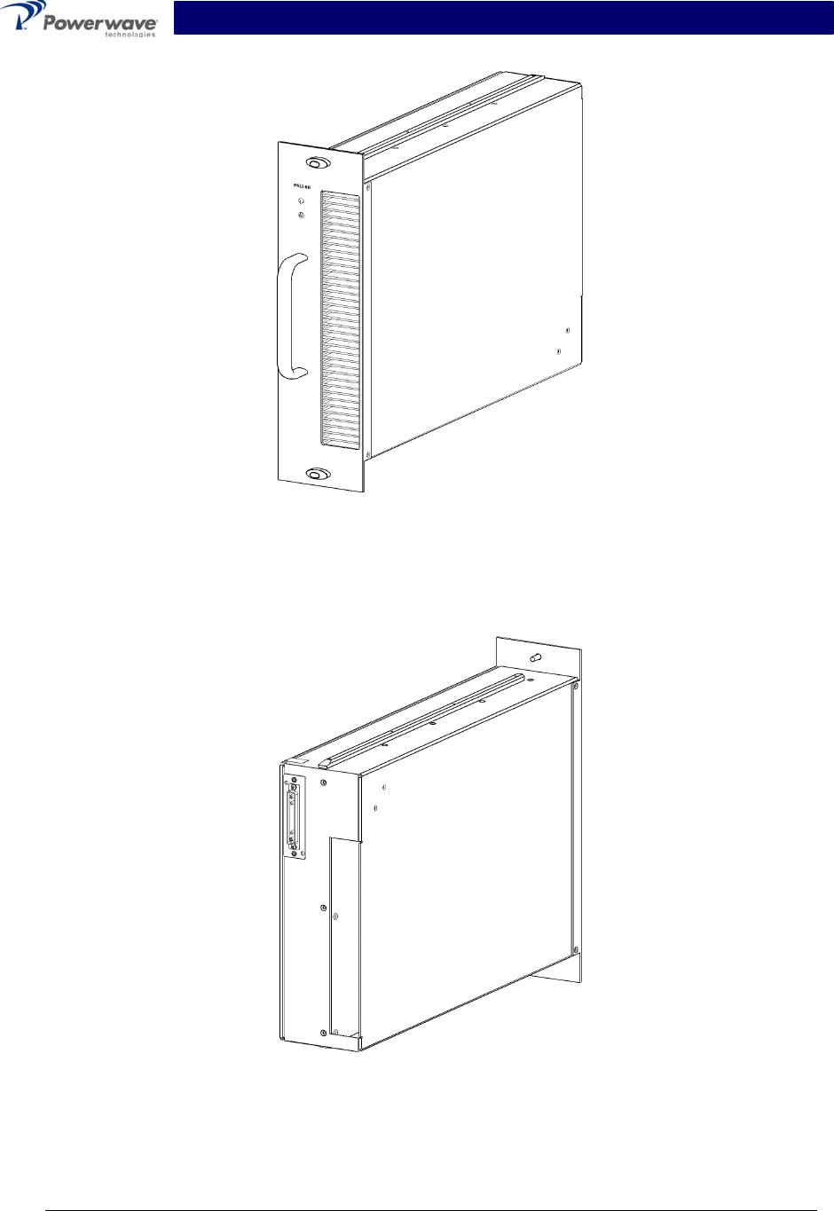
Table 1-3 G3L-1929-120 Amplifier Mechanical Specifications
Physical Dimension of
MCPA (inches)
Front panel: 13.98 W x 3.90 H x 0.118 D
Body: 11.61 W x 3.75 H x 17.56 D
Weight Approximately 28.6 pounds (13 killograms)
Connector Type D-sub, Hybrid, Plug-in Type RF connector: PKZ 26-0020 series
straight plug type (Phoenix Co.) refers to attached drawing.
MCPA Front Panel
Switch On/Off Switch and +27 Vdc Power Indicator
Pin Outs
A1 RF Input (Coaxial Contact)
A2 +27 Vdc (Power Contact)
A3 Ground (Power Contact)
A4 RF Output (Coaxial Contact)
1 TX H 10 +27 V
2 TX L 11 COM SV
3 GND 12 AMP AO
4 RX H 13 AMP A1
5 RX L 14 AMP A2
6 GND 15 AMP A3
7 HERE LPA 16 NC
8 FF LPA 17 NC
21WA4 Connector
Description
9 RESERVED
Front Panel LED Display: LED type: SMD
RUN Green (When MCPA is enabled)
ALM Red (When any alarm occurred, LED is on)
DC Green (When DC Power is ON, LED is on)
Table 1-4 G3L-1929-120 Amplifier Environmental Specifications
Operating Temperature -10 to + 60° C
Storage Temperature -40 to + 85° C
Relative Humidity 5 to 95% RH (non-condensing)
Copyright Powerwave Technologies, Inc., May 2003. All rights reserved
044-05138 Rev. A 1-3 May 2003
G3L-1929- Installation and Service Manual
Figure 1-1 Model G3L-1929-120 Amplifier Front Isometric View
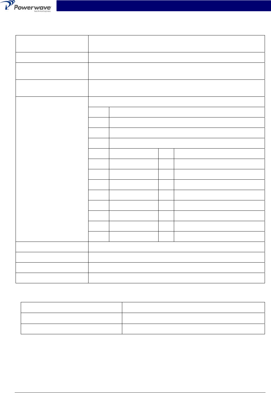
Figure 1-2 Model G3L-1929-120 Amplifier Rear Isometric View
Copyright Powerwave Technologies, Inc., May 2003. All rights reserved
044-05138 Rev. A 1-4 May 2003
G3L-1929- Installation and Service Manual
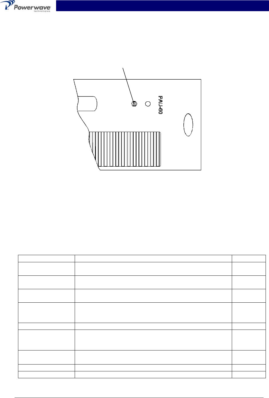
Figure 1-3 Model G3L-1929-120 Amplifier Top View
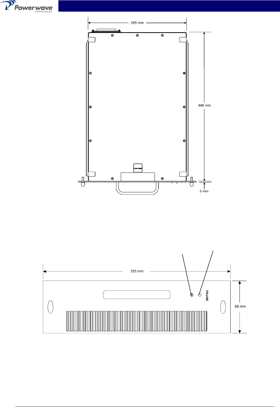
Power
ON/OFF
Switch
LED
Indicator
Figure 1-4 Model G3L-1929-120 Amplifier Front Panel
Copyright Powerwave Technologies, Inc., May 2003. All rights reserved
044-05138 Rev. A 1-5 May 2003

G3L-1929- Installation and Service Manual
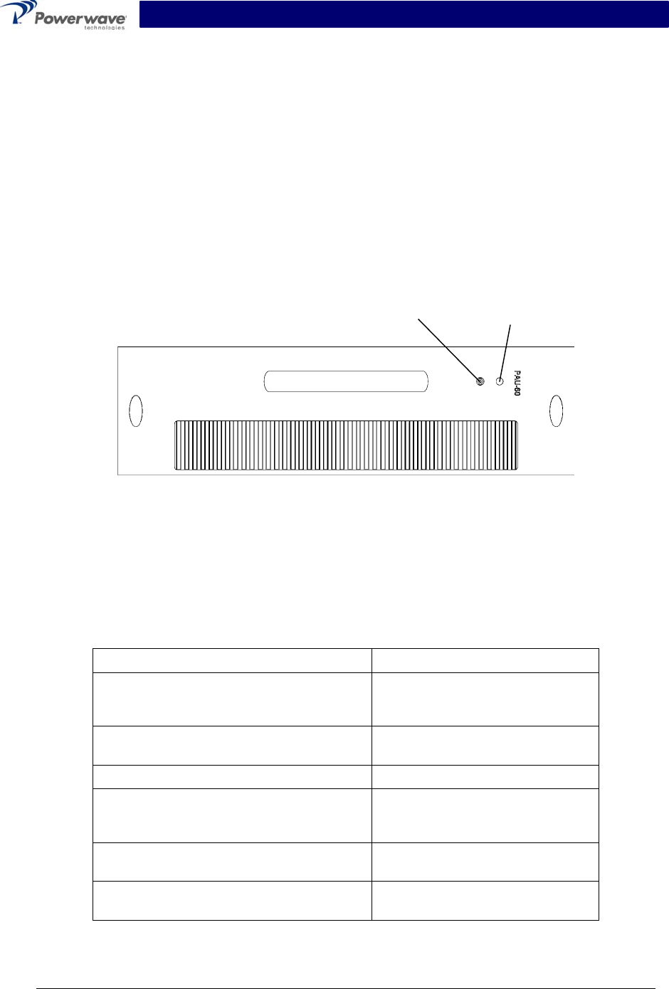
l
l
21WA4
Connector
Figure 1-5 Model G3L-1929-120 Amplifier Rear Panel
Figure 1-6 Model G3L-1929-120 Amplifier Side View
Copyright Powerwave Technologies, Inc., May 2003. All rights reserved
044-05138 Rev. A 1-6 May 2003

G3L-1929- Installation and Service Manual
Section 2. Installation
2-1 Introduction
This section contains unpacking, inspection, installation instructions and recommendations for
the G3L-1929-120 Multi-Carrier Power Amplifier (MCPA). It is important that the licensee perform
the following tasks correctly.
1. Carefully read all material in this section prior to equipment unpacking or installation.
2. Also, read and review the operating procedures in section 3 prior to installing the equipment.
3. If applicable, carefully review the government and local codes as they apply to your installa-
tion.
2-2 Site Survey
Powerwave Technologies recommends that site surveys be performed by qualified individuals or
firms prior to equipment ordering or installation. Performing a detailed site survey will reduce or
eliminate installation and turn-up delays caused by oversights. Pay particular attention to power
plant capacity, air conditioning needs, and RF/DC cabling/breaker requirements.
2-3 Electrical Service Recommendations
Powerwave recommends that:
• Proper AC line conditioning and surge suppression be provided on the primary AC input to
the +27 Vdc power source.
• All electrical service should be installed in accordance with any applicable codes, and good
engineering practice.
• Straight, short ground runs be used.
• The electrical service must be well grounded.
Each amplifier system should have its own circuit breaker, so a failure in one does not shut off
the whole installation. Circuit breakers should be capable of handling the anticipated inrush cur-
rent, in a load center with a master switch.
2-4 Air Conditioning
Each G3L-1929-120 amplifier generates approximately 2300 BTUs of heat at full power. A 1-ton
air conditioner sufficiently handles 12,000 BTUs of heat.
2-5 Unpacking and Inspection
This equipment (as applicable) has been operated, tested and calibrated at the factory. Carefully
open and remove the MCPAs from their respective containers. Retain all packing material that
can be reassembled in the event that the unit must be returned to the factory. Please perform the
following steps:
CAUTION
Exercise care in handling equipment during inspection to prevent damage caused by
rough or careless handling.
Copyright Powerwave Technologies, Inc., May 2003. All rights reserved
044-05138 Rev A 2-1 May 2003

G3L-1929- Installation and Service Manual
1. Visually inspect the MCPA for damage that may have occurred during shipment.
2. Check for evidence of water damage, bent or warped chassis, loose screws or nuts, or ex-
traneous packing material in the connector(s).
CAUTION
Before applying power, make sure that all connectors are secure. Make sure that the
input and output are properly terminated at 50 ohms. Do not operate the system with-
out a load attached. Refer to section 1, table 1-2 for input power requirements. Exces-
sive input power may damage the equipment.
If possible, inspect the equipment in the presence of the delivery person.
If the equipment is damaged:
The carrier is your first area of recourse.
A claim should be filed with the carrier once the extent of any damage is assessed. We can-
not stress too strongly the importance of IMMEDIATE careful inspection of the equipment
and the subsequent IMMEDIATE filing of the necessary claims against the carrier, if neces-
sary.
If the equipment is damaged and must be returned to the factory:
Please write or phone for return authorization.
Powerwave may not accept returns without a return authorization.
Claims for loss or damage may not be withheld from any payment to Powerwave nor may any
payment due be withheld pending the outcome thereof. WE CANNOT GUARANTEE THE
FREIGHT CARRIER'S PERFORMANCE
2-6 Installation Instructions
Proceed with the installation of the G3L-1929-120 Amplifier as follows:
WARNING
Turn off external primary DC power before connecting DC power cables.
1. Inspect the 21WA4 male combo connector on the rear of each amplifier. Verify that all pins
are straight, no pins are recessed, and that the alignment shield is not bent.
2. Place the amplifier power On/Off switch in the “Off” position (figure 2-1).
CAUTION
Do not slam the amplifier into the subrack. Forcing the amplifier into the subrack at to
fast a rate may cause the pins on the 21-D sub connector of the amplifier to become
recessed or broken.
3. Install the amplifier(s) into their respective subrack. There are no slot priorities, so any slot
will function equally. Tighten the thumbscrews to secure the amplifier(s) to the subrack.
WARNING
Check your work before applying DC voltage to the amplifier. Make certain all con-
nections are tight and correct.
Copyright Powerwave Technologies, Inc., May 2003. All rights reserved
044-05138 Rev A 2-2 May 2003
G3L-1929- Installation and Service Manual
4. Measure primary DC input voltage. DC input voltage should be +27 Vdc ±1.0 Vdc. If the DC
input voltage is above or below the limits, call and consult Powerwave before you turn on
your amplifier system.
5. Refer to section 3 for initial turn-on and checkout procedures.
Power switch positions:
Off/On/Reset (momentary)
Front
Figure 2-1 G3L-1929-120 Power Switch Functions
2-7 Amplifier Module Power, Alarm, Control, and RF Connector
The power, alarm, control, and RF connections on the amplifier are made through a 21WA4 male
connector, located on the rear of the amplifier, and are listed and described in table 2-1 below.
Table 2-1 G3L-1929-120 MCPA Alarms & Controls
Items Specifications Remarks
Alarms & Controls TTL Level; +5 Volts
Buffer: 74ABT244 (5 V) - recommended
Deletion Alarm When unit does not exist (HEAR_PAU)
Equipped: GND Deletion OPEN
D-Line
Function Fail Alarm When unit does not exist (HEAR_PAU)
Normal: High Abnormal GND
D-Line
VSWR Alarm 3:1 (6 dB ± 1dB) @ 35 dBm-48 dBm Output Power. PAU
remains normal operation when this alarm condition disap-
pears (NOT shutdown)
RS-485
High Temp. Alarm This alarm only at +75 ºC +5
ºC/
/-0
ºC (heat-sink temp.) RS-485
Over Power Output
Alarm
Output power is greater than +48.5 dBm ±0.5 dB (70.8 W).
MCPA recovers when the alarm condition disappears.
(NOT shutdown).
RS-485
DC Fail Alarm +20.5 Vdc ± 0.5V or +29 Vdc ± 0.5V. When this alarm oc-
curs the MCPA shuts down
RS-485
Loop Fail Alarm When an alarm occurs on the feed forward path. RS-485
EN/DISABLE Reserved RS-485
Copyright Powerwave Technologies, Inc., May 2003. All rights reserved
044-05138 Rev A 2-3 May 2003
G3L-1929- Installation and Service Manual
Section 3. Operating Instructions
3-1 Introduction
This section contains a description of the G3L-1929-120 Multi-Carrier Power Amplifier (MCPA)
controls and indicators and initial start-up and operating procedures.
3-2 Controls and Indicators
The controls and indicators for the G3L-1929-120 Power Amplifier consist of the primary power
On/Off/Reset switch and status indicator LED as shown in figure 3-1.
Power
On/Off/Reset
Toggle Switch
Status
Indicator
LED
Figure 3-1 G3L-1929-120 Controls and Indicators
3-2.1 Status Indicator LED
The status indicator LED is located on the MCPA front panel as shown in figure 3-1. The LED
has tri-color capability: red, yellow, and green. The LED’s blinking frequency is 0.5 – 1 Hz with a
duty cycle of 45 – 55%. The LED indicates the status of the MCPA as listed in table 3-1.
Table 3-1 Status Indicator Colors
LED Color MCPA Status
Red (stable) Manual main-switch turned standby
and no TCP/UDB connection estab-
lished
Red (stable) LED lighting period 1.5±
±0
0.
.5
5
s
se
ec
c Manual main-switch turned ON or
MCPA is resetting
Yellow (blinking) MCPA in self-heating state
Yellow (stable) In startup phase, MCPA is in standby
state and before state change mes-
sage from MCPA
LED state as it was before disconnection TCP/IP connection is lost for two
minutes
Yellow (stable) TCP/IP connection is lost and MCPA
is in standby state
Copyright Powerwave Technologies, Inc., May 2003. All rights reserved
044-05138 Rev. A 3-1 May 2003

G3L-1929- Installation and Service Manual
3-3 Initial Start-Up and Operating Procedures
To perform the initial start-up, proceed as follows:
1. Verify that all input and output cables are properly connected.
CAUTION
Before applying power, make sure that the input and output of the amplifier are prop-
erly terminated at 50 ohms. Do not operate the amplifier without a load attached. Re-
fer to table 1-1 for input power requirements. Excessive input power may damage the
MCPA.
NOTE
The output coaxial cable between the amplifier and the antenna must be 50-ohm co-
axial cable. Use of any other cable will distort the output.
2. Turn on the supply that provides +27 Vdc to the amplifier.
3. Place the power On/Off/Reset switch on the amplifier front panel to the On (middle) position.
4. Allow the amplifiers to warm up for at least 20 minutes before taking power readings.
Copyright Powerwave Technologies, Inc., May 2003. All rights reserved
044-05138 Rev. A 3-2 May 2003

G3L-1929- Installation and Service Manual
Section 4. Principles of Operation
4-1 Introduction
This section contains a functional description of the G3L-1929-120 Multi-Carrier Power Amplifier
(MCPA).
4-2 RF Input Signal
The maximum input power for all carrier frequencies to the amplifier should not exceed the limits
specified in the appendix A specifications.
4-3 RF Output Load
The load impedance should be as good as possible (VSWR of 1.5:1 or better) in the working
band for good power transfer to the load. If the amplifier is operated into a filter, it will maintain its
distortion characteristics outside the signal band even if the VSWR is infinite, provided the re-
flected power does not exceed one watt. A parasitic signal of less than one-watt incident on the
output will not cause distortion at a higher level than the normal forward distortion (i.e. –65 dBc).
4-4 Multi-Carrier Power Amplifier (MCPA) Functional Description
The MCPA is a linear, feed-forward multi-carrier power amplifier that operates in the 60 MHz fre-
quency band from 1930 MHz to 1990 MHz (refer to table 1-4 for amplifier specifications). The
amplifier provides a gain of 60 dB to provide a typical output of 70 watts (48.8 dBm). Refer to fig-
ure 4-1 for the amplifier functional block diagram. Each amplifier is a self-contained module and
is functionally independent of any other MCPA in a system. The amplifiers are designed for paral-
lel operation to achieve high peak power output. Each MCPA has an alarm board that monitors
the amplifier performance. If a failure or fault occurs in an MCPA, it is transmitted to a subrack
system via the D-subminiature 21WA4 connector at the rear of the module. The subrack reports
all alarms to the host system.
Continuously comparing active paths with passive references, and correcting for small variations
through RF feedback controls maintain constant gain. All gain variations, for example those due
to temperature, are reduced to the passive reference variations. The amplifier consists of the fol-
lowing major functions:
• Preamplifier
• Main amplifier
• Error amplifier
• Alarm monitoring and control
• First and second loop control circuits
• Pilot tone generator
Copyright Powerwave Technologies, Inc., May 2003. All rights reserved
044-05138 Rev. A 4-1 May 2003
G3L-1929- Installation and Service Manual
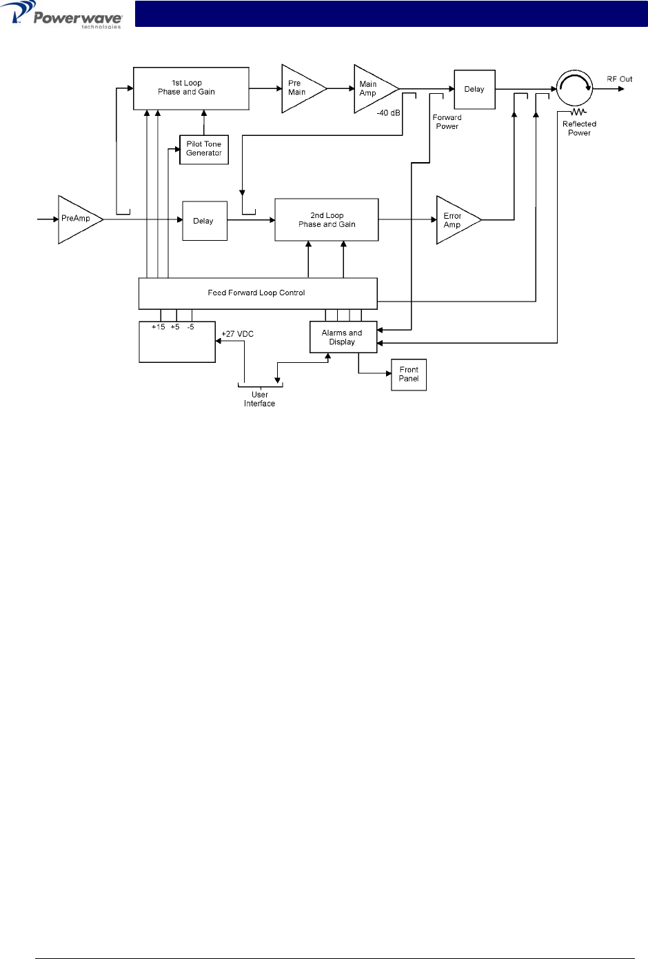
Figure 4-1 Multi-Carrier Power Amplifier Functional Block Diagram
4-4.1 Preamplifier
The carrier is applied to the input port of the amplifier. This signal is fed to the preamplifier stage
where it is amplified using two stages of class A mode amplifiers. The output of the preamplifier is
then split into two paths, one to the main amplifier and one to the error amplifier.
4-4.2 Main and Error Amplifiers
The main amplifier provides approximately 14.5 dB of gain in the 1930 to 1990 MHz frequency
band (refer to table 1-2 for amplifier specifications). The main amplifier employs class AB amplifi-
cation for maximum efficiency. The error amplifier and feed forward loops are used to correct sig-
nal non-linearity’s introduced by the class AB main amplifier. The error amplifier operates in class
A mode. The RF signal from the preamp is coupled to an attenuator and phase shifter in the first
feed-forward loop where it is phase shifted by 180 degrees and amplified in the premain ampli-
fier. The output from the premain amplifier is fed to the class AB main amplifier. The signal output
from the main amplifier is sampled using a coupler, and the sample signal is combined with the
main input signal and input to the second feed-forward loop.
The error signal is attenuated, phase shifted 180 degrees, then fed to the error amplifier where it
is amplified to a level identical to the sample output from the main amplifier. The output from the
error amplifier is then coupled back and added to the output from the main amplifier. The control
loops continuously make adjustments to cancel out any distortion in the final output signals.
Copyright Powerwave Technologies, Inc., May 2003. All rights reserved
044-05138 Rev. A 4-2 May 2003

G3L-1929- Installation and Service Manual
4-4.3 Alarm Monitoring and Control
The alarm logic controls the +5 Vdc bias voltage that shuts down the amplifier. During routine op-
eration, all normal variations are automatically compensated for by the feed-forward loop control.
However, when large variations occur beyond the adjustment range of the loop control, a loop
fault occurs. When this happens, an alarm indicator is illuminated on the front panel of the
subrack. The fault is transmitted back to an external summary module via the external alarm in-
terface connection on the front panel of the subrack.
4-4.4 First and Second Loop Control Circuits
The primary function of the first loop is to provide an error signal for the second loop. The primary
function of the second loop is to amplify the error signal to cancel out spurious products devel-
oped in the main amplifier. The input signal is amplified by a preamplifier and fed to a coupler and
delay line. The signal from the coupler is fed to the attenuator and phase shifter in the first loop.
The first loop control section phase shifts the main input signals by 180 degrees and constantly
monitors the output for correct phase and gain.
The second loop control section obtains a sample of the distortion added to the output signals by
the main amplifiers. The signal is phase shifted 180 degrees, then fed to the error amplifier where
it is amplified to the same power level as the input sample. The signal is then coupled to the error
signal of the main amplifier output. The final output is monitored by the second loop and adjusted
to ensure that the signal distortion and intermodulation distortion (IMD) on the final output is can-
celled out.
4-4.5 Pilot Tone Generator
The basic idea of injecting a pilot tone is that if the pilot signal is suppressed, then the distortion
from the main amplifier is also suppressed. To accomplish this, the pilot tone generator signal is
injected into the first loop and then detected at the feedforward output using the original pilot tone
as a reference. The information is then fed back to control the gain and phase such that the out-
put distortion is minimized.
4-5 Amplifier Module Cooling
The amplifier is cooled by forced air flowing over its heat sink, which is provided by two fans
mounted on the front of the subrack. The fans draw air through the front of the system and ex-
haust hot air out the back. The fans are field replaceable. Each amplifier, when properly cooled,
maintains the amplifier within the specified operating temperature range. Six inches of free space
are required at both the front and rear panels of the subrack to allow adequate air volume to cir-
culate over the heat sinks.
4-6 Power Distribution
Primary DC power for the amplifier is provided by the host system. The amplifier module has a
DC/DC converter and voltage regulator that converts the +27 Vdc to +15 Vdc, +5 Vdc, and -5 Vdc
for internal use.
Copyright Powerwave Technologies, Inc., May 2003. All rights reserved
044-05138 Rev. A 4-3 May 2003
G3L-1929- Installation and Service Manual
Section 5. Maintenance
5-1 Introduction
This section contains periodic maintenance and performance test procedures for the G3L-1929-
120 Multi-Carrier Power Amplifier (MCPA).
NOTE
Check your sales order and equipment warranty before attempting to service or re-
pair the unit. Do not break the seals on equipment under warranty or the warranty will
be null and void. Do not return equipment for warranty or repair service until proper
shipping instructions are received from the factory.
5-2 Periodic Maintenance
Periodic maintenance requirements and the intervals at which the tasks should be performed are
listed in table 5-1.
Table 5-1 Periodic Maintenance
Task Interval Action
Inspection:
Cables and Connectors
12 Months Inspect signal and power cables for frayed insulation.
Check RF connectors to ensure that they are tight.
Performance Tests 12 Months Perform annual test per paragraph 5-4.
Clean Fans/Heat Sinks 3 Months Inspect for debris. Remove dust with a soft cloth/brush
or vacuum cleaner.
5-3 Test Equipment Required For Test
Test equipment required to test the amplifier is listed in table 5-2. Equivalent test equipment may
be substituted for any item, keeping in mind that a thermistor type power meter is required.
NOTE
All RF test equipment required must be calibrated to 0.05 dB resolution. Any devia-
tion from the nominal attenuation must be accounted for and factored into all
output readings.
Table 5-2 Test Equipment Required
Nomenclature Manufacturer Model
Signal Generator H.P. 8656B
20 dB Attenuator, 250 Watt Bird Tenuline
20 dB Attenuator, 20 Watt (2 each) Bird Tenuline
Spectrum Analyzer H.P. 8560E
Coax Directional Coupler H.P. 778D
Power Meter / Sensor H.P. 437B / 8481A
Arbitrary Waveform Generator Sony AWG2021
Network Analyzer H.P. 8753C
Copyright Powerwave Technologies, Inc., May 2003. All rights reserved
044-05138 Rev. A 5-1 May 2003

G3L-1929- Installation and Service Manual
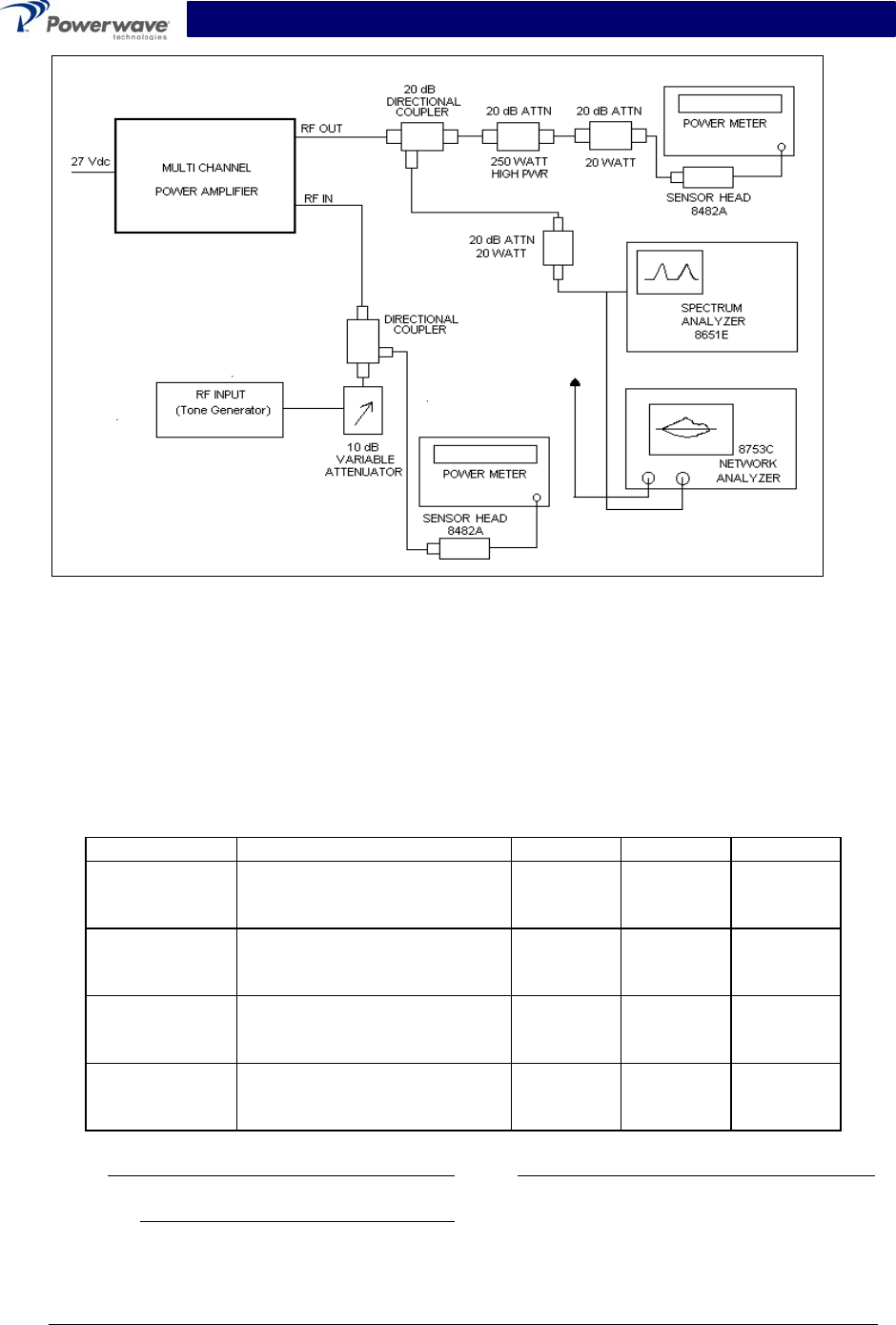
5-4 Performance Test
Performance testing should be conducted every 12 months to ensure that the amplifier system
meets the operational specifications listed in Table 5-3. Also verify system performance after any
amplifier module is replaced in the field. The test equipment required to perform the testing is
listed in table 5-2, and the test setup is shown in figure 5-1.
NOTE
The frequencies used in this test are typical for an amplifier with a 60 MHz band from
1930 MHz to 1990 MHz. Select evenly spaced F1, F2, F3, and F4 frequencies that cover
the instantaneous bandwidth of your system.
5-4.1 Amplifier Performance Test
To perform these tests, proceed as follows:
Connect test equipment as shown in figure 5-1.
WARNING
Do not apply any RF signals at this time.
5-4.1.1 Amplifier Spurious Emissions Test:
With the RF input signal to the amplifier set to be as shown in Figure 5-1, use the spectrum ana-
lyzer to measure the spurious emissions performance. Record test data in Table 5-3. Verify that it
is within the specifications shown in table 1-2. Switch tested amplifier to OFF.
5-4.1.2 Gain Test:
1. Disconnect spectrum analyzer from test setup, and connect the network analyzer.
2. Set network analyzer as follows:
A. Power output to -10 dBm max.
B. Frequency start to 1930 MHz.
C. Frequency stop to 1990 MHz.
D. Normalize the network analyzer for gain and return loss.
3. Check the amplifier gain across the band from 1930 MHz to 1990 MHz. Gain should be as
specified in table 1-1. Record test data in table 5-3.
5-4.1.3 Input Return Loss:
Read and record the S11 return loss measurement on network analyzer. Record test data in table
5-3.
Copyright Powerwave Technologies, Inc., May 2003. All rights reserved
044-05138 Rev. A 5-2 May 2003
G3L-1929- Installation and Service Manual
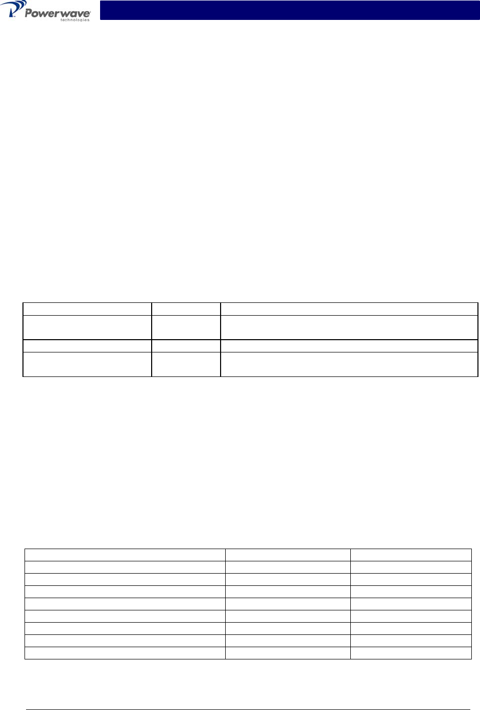
Figure 5-1 Amplifier Test Setup Diagram
Table 5-3 G3L-1929-120 Amplifier Test Data Sheet
DATE _________________________________ MODULE S/N _________________________
Test Conditions:
Load and Source Impedance: 50 Ohms
VSWR: < 1.5:1
Supply Voltage: +27 Vdc ±0.1 Vdc
Test Specification Min Max Data
RF Gain
Vcc = 27 Vdc
PO = See table 1-4
Freq. = 1930 – 1990 MHz
57.0 dB 58.0 dB
Spurious
Emissions
Vcc = 27 Vdc
PO = See table 1-4
1930 – 1990 MHz Band
-65 dBc
Gain Flatness Vcc = 27 Vdc
PO = See table 1-4
1930 – 1990 MHz Band
±0.5 dB
Input Return
Loss
Vcc = 27 Vdc
PO = See table 1-4
1930 – 1990 MHz Band
-14 dB
PASS FAIL
Tested by
Copyright Powerwave Technologies, Inc., May 2003. All rights reserved
044-05138 Rev. A 5-3 May 2003

G3L-1929- Installation and Service Manual
5-5 Field Replacement of the Module
The GL3-1929-120 multi-carrier power amplifier module can be replaced in the field on site by a
qualified technician with experience maintaining RF power amplifiers and similar equipment:
To replace a power amplifier module, proceed as follows:
1. Set On/Off switch on the front panel of the amplifier module to Off (down).
2. Loosen the two thumbscrews that secure amplifier module to the subrack.
CAUTION
When removing the amplifier from the subrack, it is very important to support the am-
plifier such that the rear of the module does not suddenly drop when the guide rail
disengages from the track. A drop such as this could damage the rear 21WA4 multipin
connector.
3. With steady even pressure, use handle on front of amplifier to pull module out of subrack.
4. Install replacement in reverse order of steps 1 through 3 above.
Copyright Powerwave Technologies, Inc., May 2003. All rights reserved
044-05138 Rev. A 5-4 May 2003

G3L-1929- Installation and Service Manual
Section 6. Troubleshooting
6-1 Introduction
This section contains a list of problems that could occur and a few suggested actions that can
correct the problem. If the suggested corrective action does not eliminate the problem, please
contact your Powerwave field representative or the factory for further instructions (refer to para-
graph 6-3).
NOTE
Check your sales order and equipment warranty before attempting to service or re-
pair the unit. Do not break the seals on equipment under warranty or the warranty will
be null and void. Do not return equipment for warranty or repair service until proper
shipping instructions are received from the factory.
6-2 Troubleshooting
Refer to table 6-1 for troubleshooting suggestions.
Table 6-1. Troubleshooting.
Problem Suggested Action
G3L-1929-120 Inoperative
1. Set On/Off/Reset toggle switch momentarily to Reset.
2. Check for proper power supply voltage.
3. Verify all RF connections.
4. Verify that unit does not have a major fault (red LED on
front panel of subrack).
5. Contact your field representative or factory.
6-3 Return For Service Procedures
When returning products to Powerwave, the following procedures will ensure optimum response.
6-3.1 Obtaining An RMA
A Return Material Authorization (RMA) number must be obtained prior to returning equipment to
the factory for service. Please contact our Repair Department at (714) 466-1000 to obtain this
number, or FAX your request to (714) 466-5800. Failure to obtain this RMA number may result in
delays in receiving repair service.
6-3.2 Repackaging For Shipment
To ensure safe shipment of the amplifier, it is recommended that the original package designed
for shipping the amplifier be reused. If it is not available, contact Powerwave’s Customer Service
Department for packing materials.
Copyright Powerwave Technologies, Inc., May 2003. All rights reserved
044-05138 Rev. A 6-1 May 2003