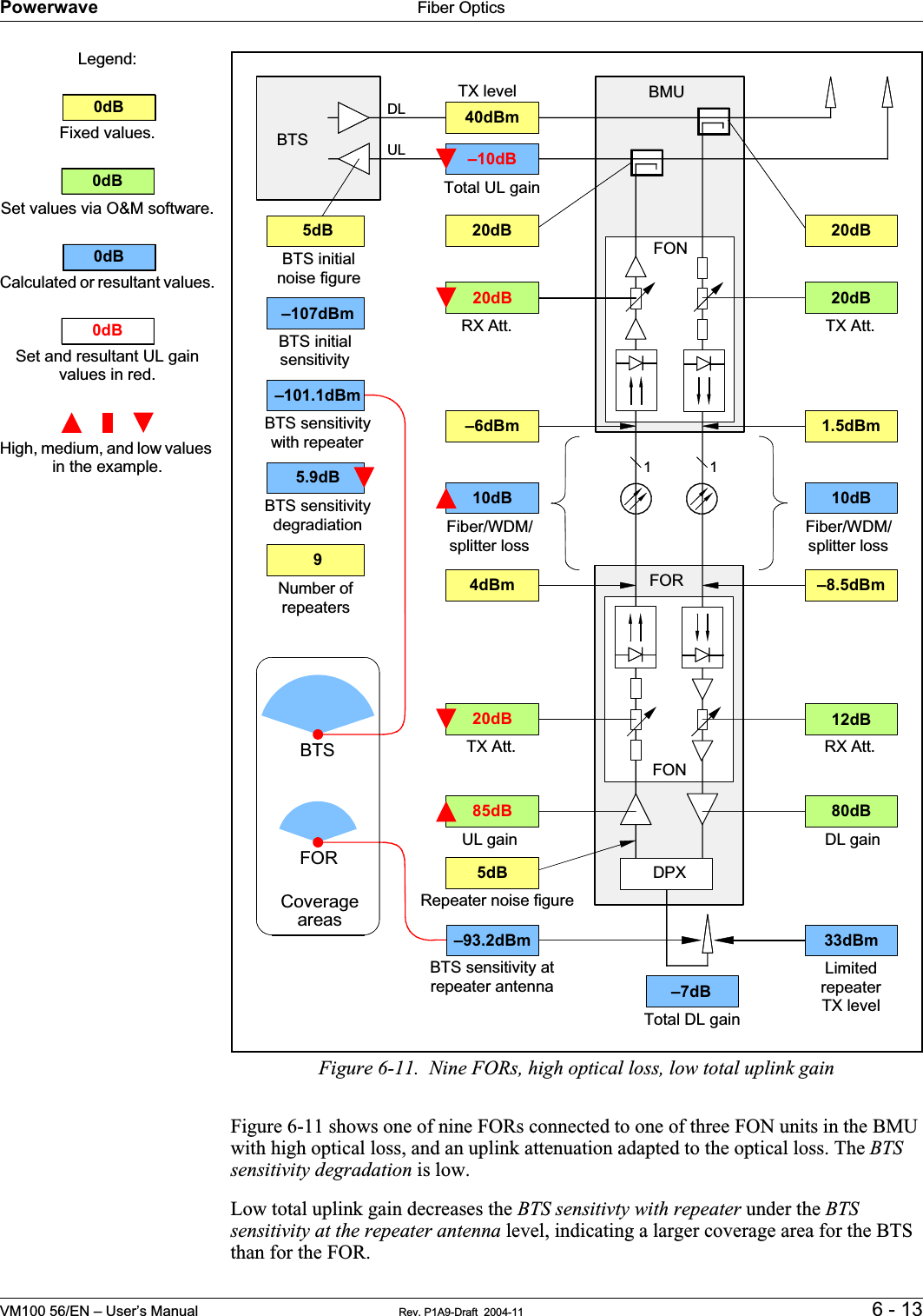
Powerwave Technologies 5JS0073 Fiber-Fed Repeater/Radio Head User Manual VM10056 EN Rev P1A9 Draft
Powerwave Technologies Inc Fiber-Fed Repeater/Radio Head VM10056 EN Rev P1A9 Draft
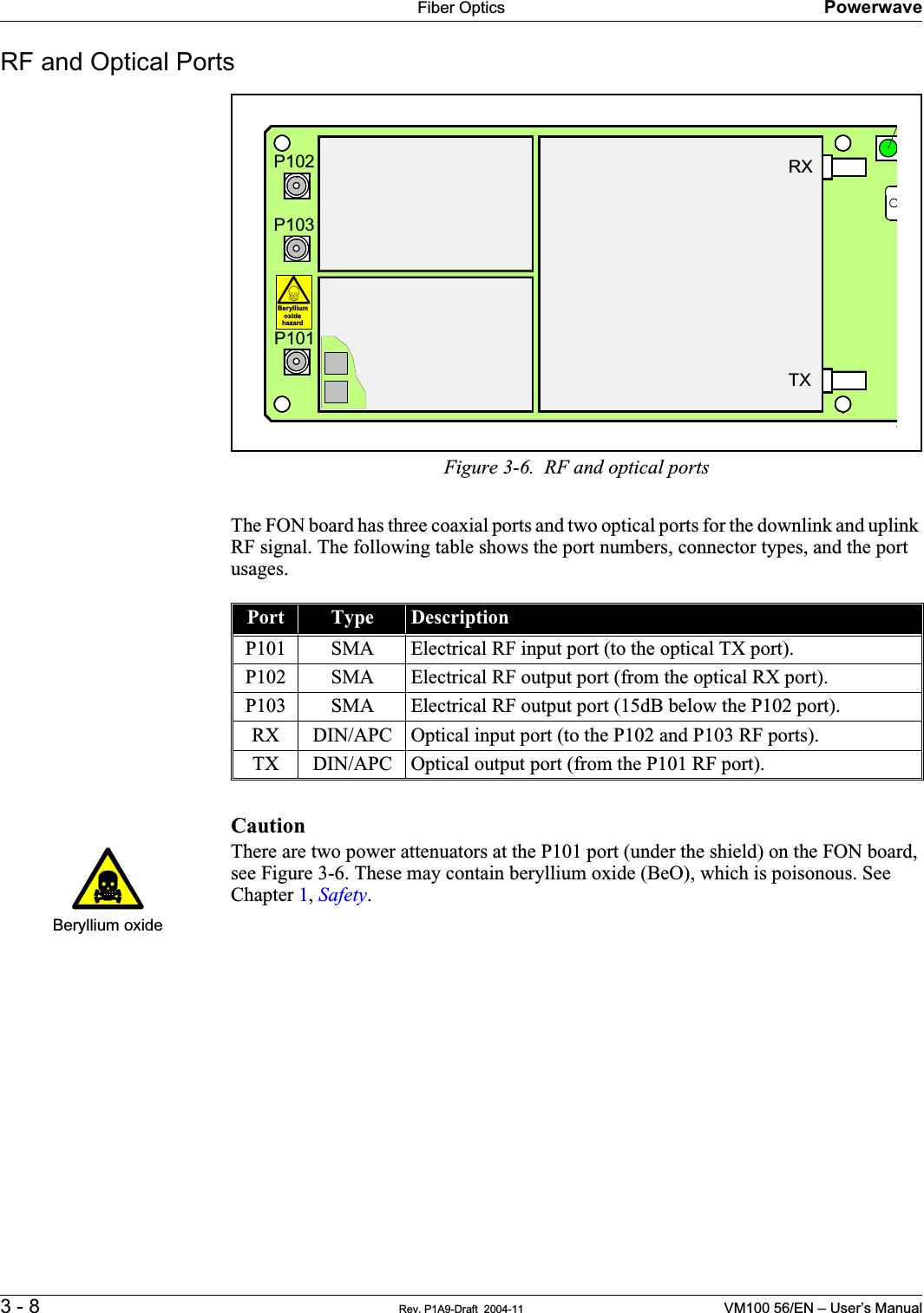
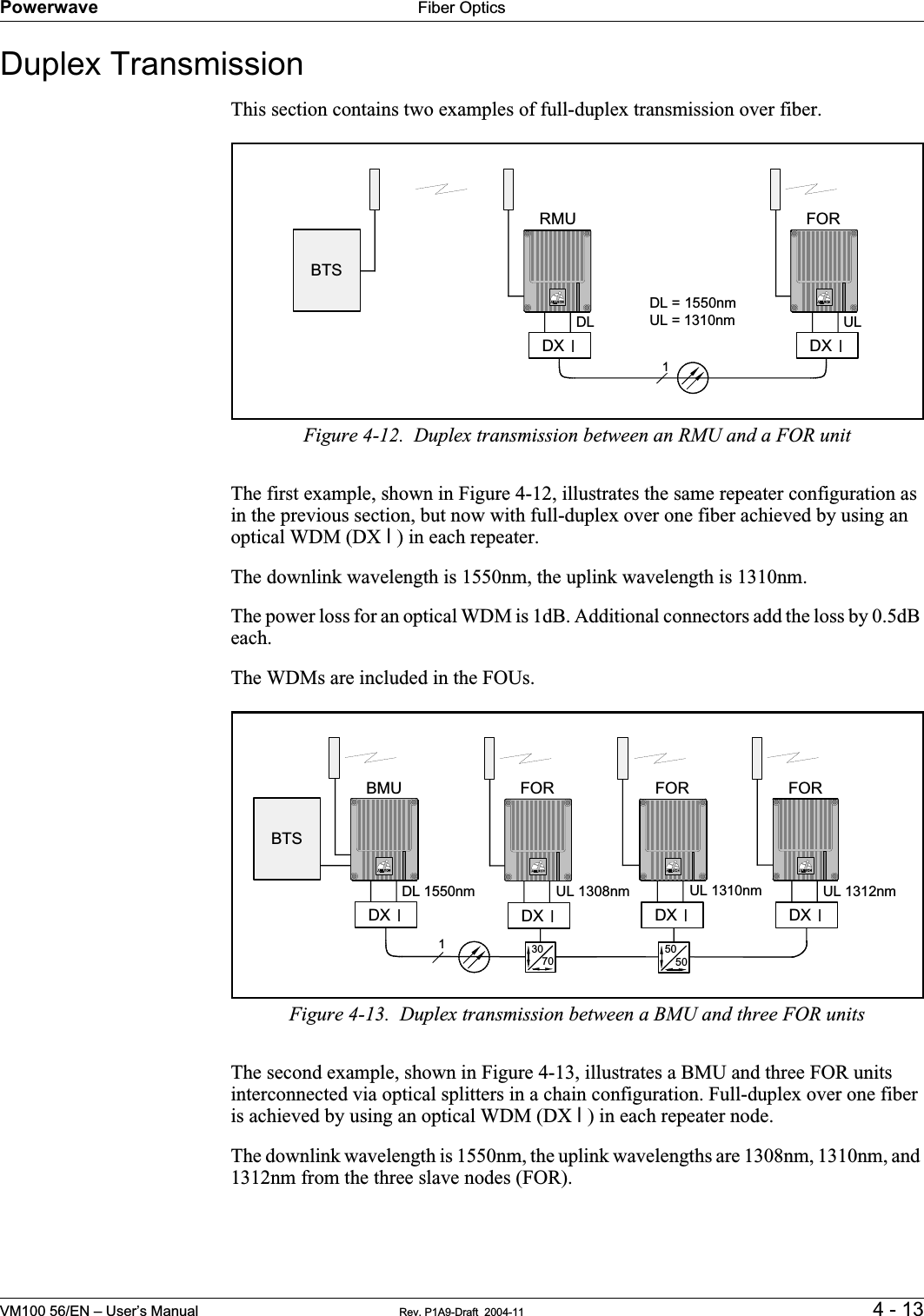
Contents
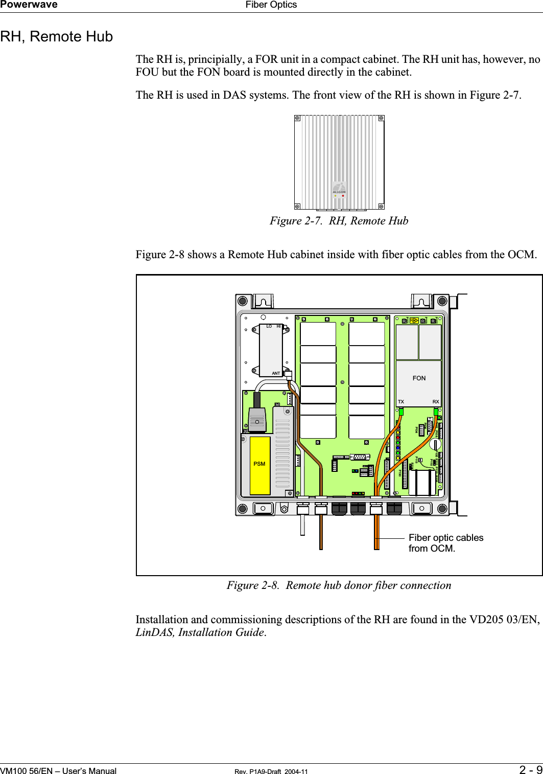
- 1. Users Manual 1
- 2. Users Manual 2
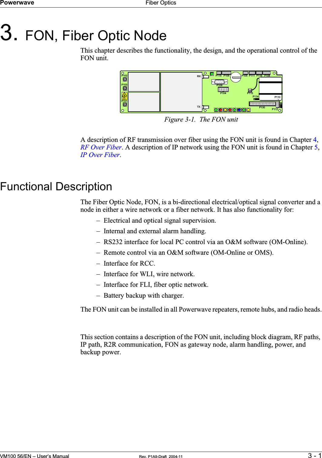
- 3. Users Manual 3
Users Manual 1