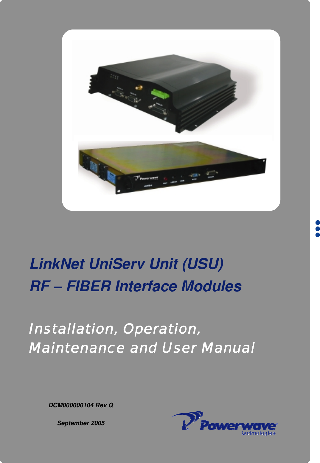
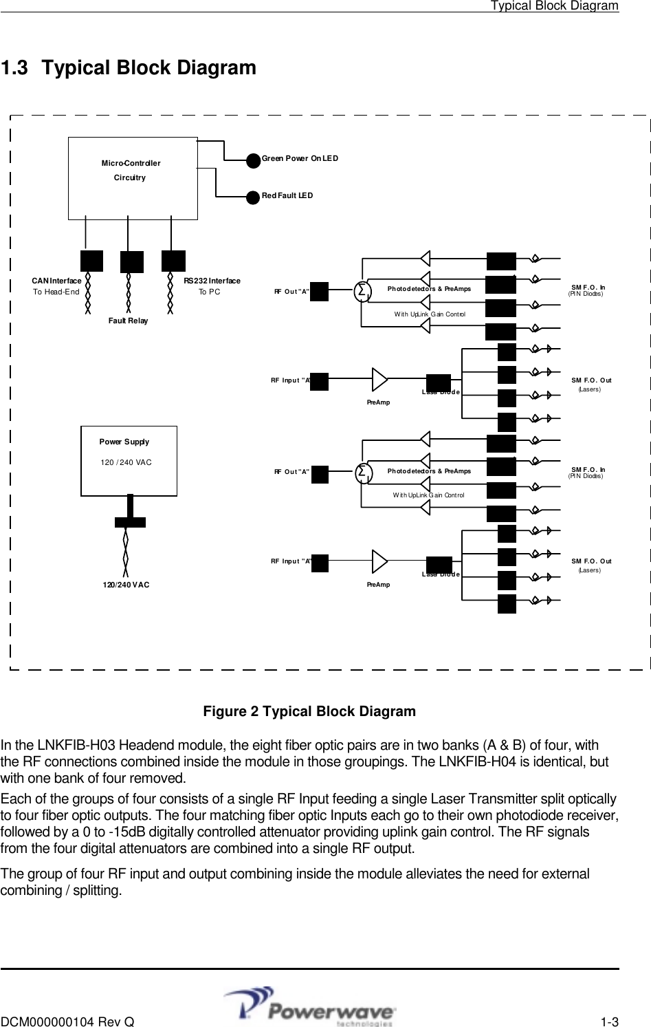
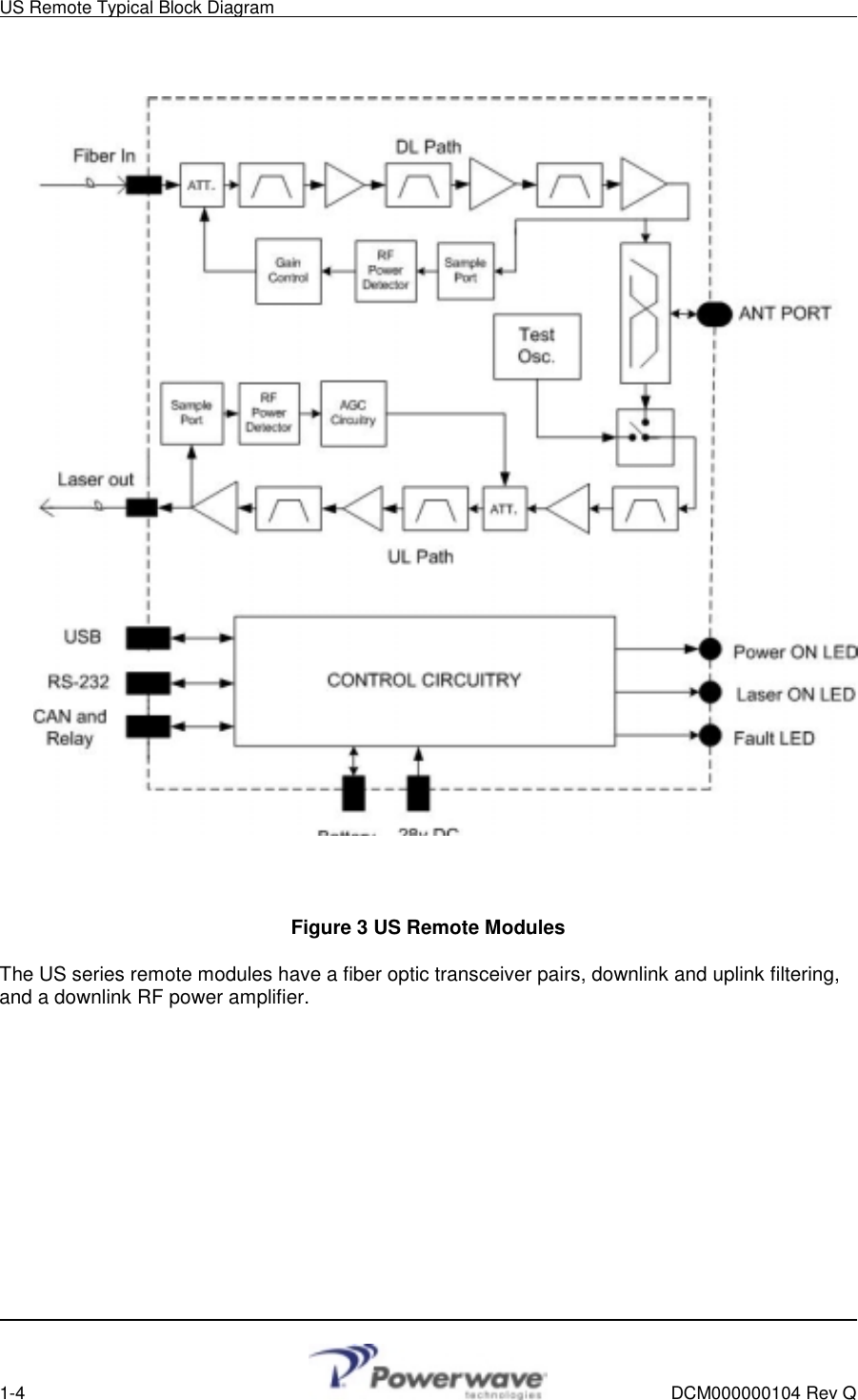
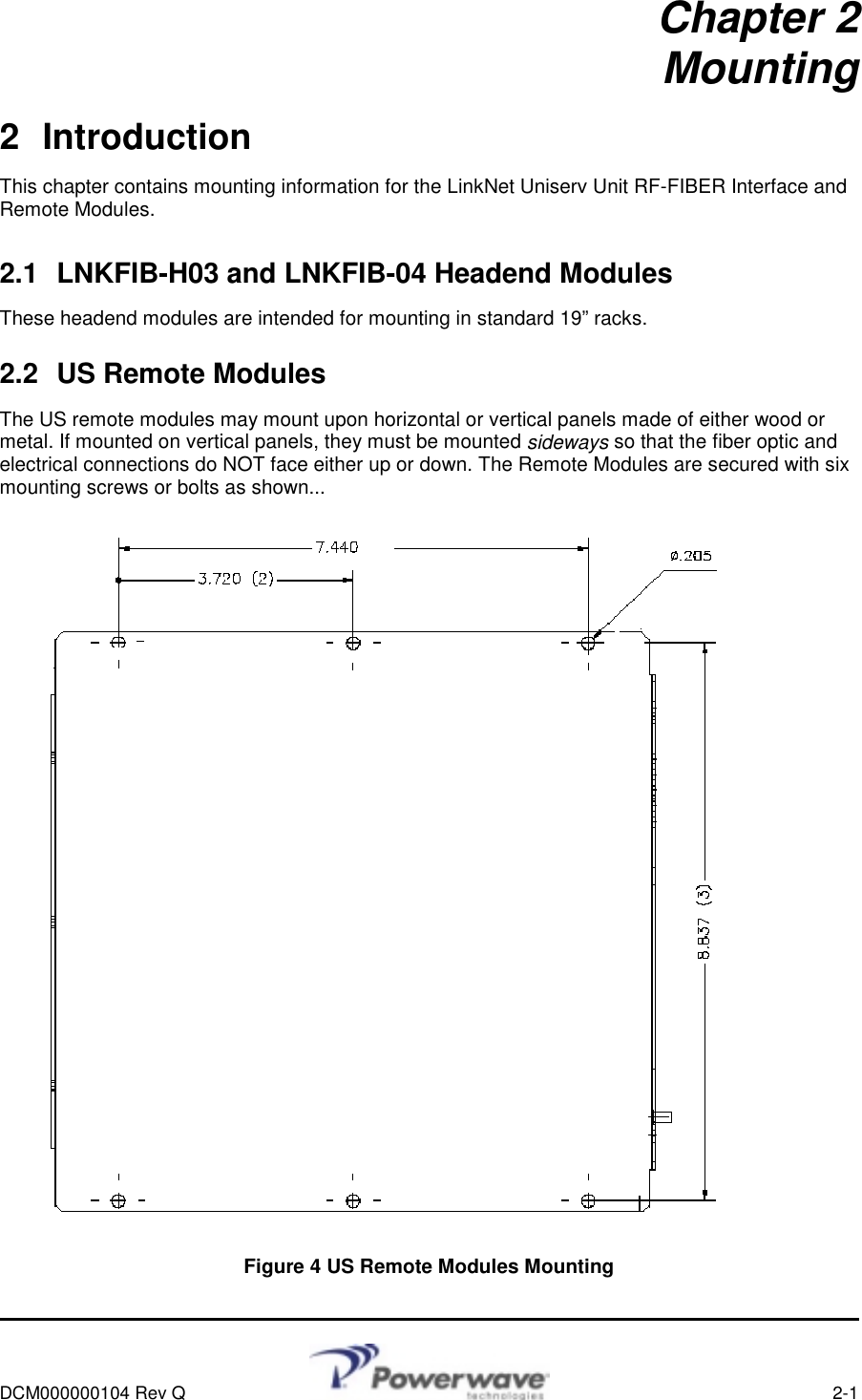
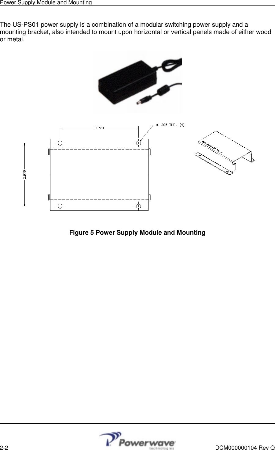
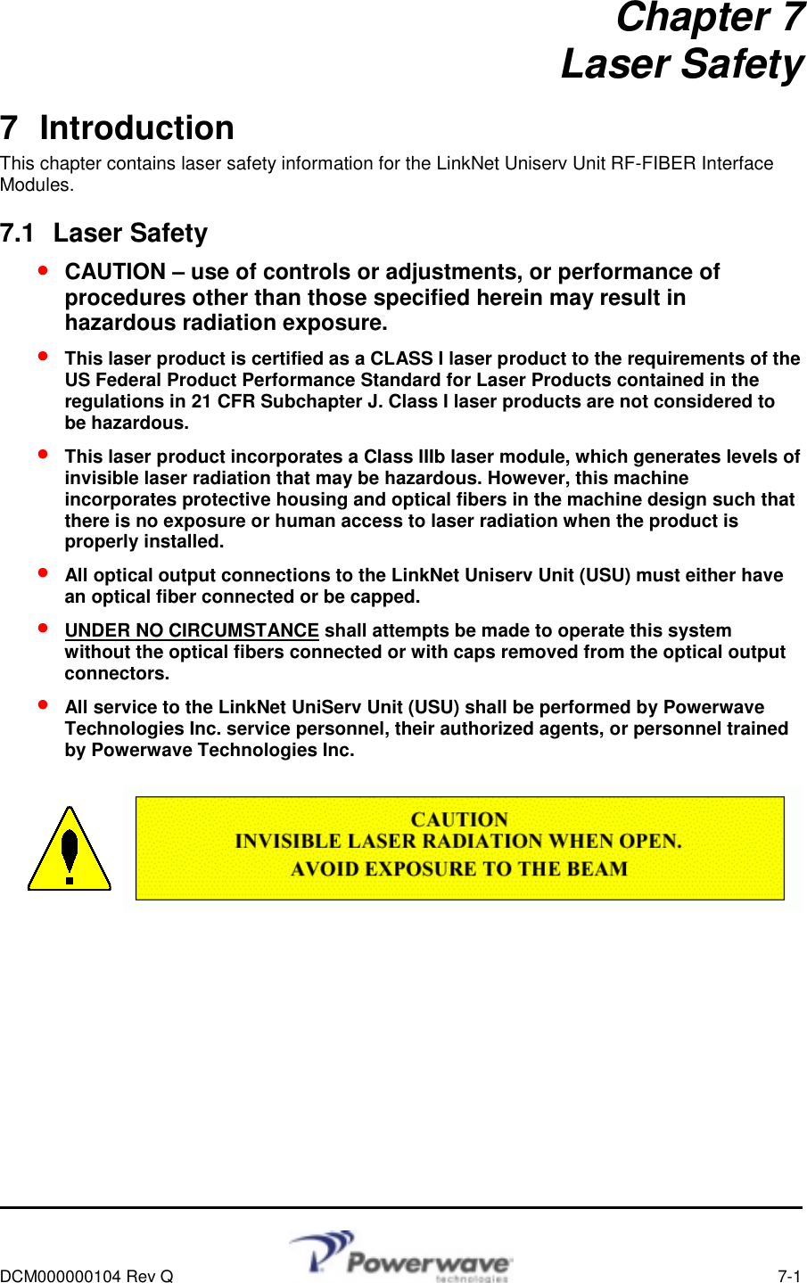
Powerwave Technologies 5JS0079 LINKNET UNISERV UNIT BOOSTER User Manual USERS MANUAL

Powerwave Technologies Inc LINKNET UNISERV UNIT BOOSTER USERS MANUAL

USERS MANUAL

          DCM000000104 Rev Q  September 2005     Installation, OperaInstallation, OperaInstallation, OperaInstallation, Operation, tion, tion, tion, Maintenance and User ManualMaintenance and User ManualMaintenance and User ManualMaintenance and User Manual    LinkNet UniServ Unit (USU)  RF – FIBER Interface Modules
             © 2005 Powerwave Technologies Incorporated. All rights reserved. Powerwave Technologies, and the Powerwave logo are registered trademarks. This Powerwave product is intended only for installation in a RESTRICTED ACCESS LOCATION and is designed to operate within the Normal Operating (typical operating) ranges or conditions specified in this document. Operation of this equipment beyond the specified ranges in this document may cause: 1. Spurious emissions that violate regulatory requirements. 2. The equipment to be automatically removed from service when maximum thresholds are exceeded. 3. The equipment to not perform in accordance with its specifications.  It is the Operator's responsibility to ensure this equipment is properly installed and operated within Powerwave operating specifications to obtain proper performance from the equipment and to comply with regulatory requirements.
  Warnings, Cautions, and Notes    DCM000000104 Rev Q    i         Warnings, Cautions, and Notes Warnings, cautions, and notes are found throughout this manual where applicable. The associated icons are used to quickly identify a potential condition that could result in the consequences described below if precautions are not taken. Notes clarify and provide additional information to assist the user.   Warning   This warning symbol means danger. You are in a situation that could cause bodily injury. Before you work on any equipment, be aware of the hazards involved with electrical and RF circuitry and be familiar with standard practices for preventing accidents.   Caution     This caution symbol means reader be careful. In this situation, the user might do something that could result in equipment damage or loss of data.   Note     This note symbol means reader take note. Notes contain helpful suggestions or references to material not covered in the document. Procedures are not contained in notes.
Revision Record       ii    DCM000000104 Rev Q  Revision Record  Revision Letter   Date of Change  Reason for Change P  July 2005  Converted Kaval Rev 15 to Powerwave Format Q  22 September 2005  Updated with US700PS
     DCM000000104 Rev Q    iii  TABLE OF CONTENTS Chapter 1 - Theory of Operation 1 Introduction....................................................................................................................1-1 1.1 THEORY OF OPERATION ..................................................................................................... 1-1 1.1.1 Typical Application........................................................................................................... 1-1 1.2 MODELS ............................................................................................................................ 1-2 1.3 TYPICAL BLOCK DIAGRAM................................................................................................... 1-3 Chapter 2 - Mounting 2 Introduction....................................................................................................................2-1 2.1 LNKFIB-H03 AND LNKFIB-04 HEADEND MODULES ........................................................... 2-1 2.2 US REMOTE MODULES....................................................................................................... 2-1 Chapter 3 - Connections 3 Introduction....................................................................................................................3-1 3.1 CONNECTIONS ................................................................................................................... 3-1 3.1.1 US Remote Module Connections .................................................................................... 3-2 3.1.2 User I/O Connection ........................................................................................................ 3-3 3.2 HEADEND TO REMOTE INTERCONNECTS .............................................................................. 3-4 3.3 FIBER OPTIC CONNECTIONS ............................................................................................... 3-4 Chapter 4 - Remote Module 4 Introduction....................................................................................................................4-1 4.1 POWER FOR THE REMOTE MODULE..................................................................................... 4-1 4.2 BATTERY BACKUP OF REMOTE MODULE.............................................................................. 4-1 4.3 MODULE SPECIFICATIONS................................................................................................... 4-2 4.4 REMOTE MODULE PER-CARRIER DERATING ........................................................................ 4-3 Chapter 5 - Operation 5 Introduction....................................................................................................................5-1 5.1 OPERATION........................................................................................................................ 5-1 5.1.1 Fault Indications...............................................................................................................5-1 5.1.2 Configuration and PC Commands ................................................................................... 5-1 5.2 GAIN ADJUSTMENTS........................................................................................................... 5-2 5.3 SIGNAL LEVEL ADJUSTMENTS ............................................................................................. 5-2 Chapter 6 - Antenna Installation 6 Introduction....................................................................................................................6-1 6.1 ANTENNA INSTALLATION ..................................................................................................... 6-1 6.2 FCC INFORMATION TO USERS ............................................................................................ 6-1 Chapter 7 - Laser Safety 7 Introduction....................................................................................................................7-1 7.1 LASER SAFETY................................................................................................................... 7-1 Chapter 8 - Return For Service 8 Introduction....................................................................................................................8-1 8.1 RETURN FOR SERVICE PROCEDURE ................................................................................... 8-1 8.1.1 Obtaining An RMA ........................................................................................................... 8-1 8.1.2 Repackaging For Shipment ............................................................................................. 8-1 8.2 PARTS AND ACCESSORIES.................................................................................................. 8-1
Table of Contents        iv    DCM000000104 Rev Q  TABLE OF FIGURES Figure 1 Typical Application ......................................................................................................... 1-1 Figure 2 Typical Block Diagram.................................................................................................... 1-3 Figure 3 US Remote Modules ......................................................................................................1-4 Figure 4 US Remote Modules Mounting ...................................................................................... 2-1 Figure 5 Power Supply Module and Mounting ............................................................................. 2-2 Figure 6 LNKFIB-H03/H04 Headend Module (Front)................................................................... 3-1 Figure 7 LNKFIB-H03/H04 Headend Module (Rear).................................................................... 3-1 Figure 8 LNKFIB-H03/H04 Headend Module Drawing (Rear) ..................................................... 3-1 Figure 9 US Remote Module Connections................................................................................... 3-2 Figure 10 ASY00420 DB15 Breakout Kit ..................................................................................... 3-3 Figure 11 Remote Module (Rear View)........................................................................................ 3-3  TABLE OF TABLES Table 1 Available Models and Descriptions ................................................................................. 1-2 Table 2 Module Specifications...................................................................................................... 4-2 Table 3 Per-Carrier Derating ........................................................................................................ 4-3
    DCM000000104 Rev Q    1-1  USU RF to FiberRemote ModulesThese may be single ormultiple units, and areusually grouped on floorsof a building, mounted inElectrical Rooms.In-BuildingAn te n na eRefer to AntennaInstallation SectionHead-End ModuleHead-End ModuleHead-End ModuleHead-End ModuleHead-End ModuleHEAD-END DISTRIBUTION CENTER REM OT E L OCAT I ONS I N BUI L DI NGAny requiredAmplifiers, Filters,Couplers, Etc.RF CableRF CableRF CableRF CableRF CableRF CablesRF Cableto/fromBase Statio n(s)SMF = Single-Mode Optical FiberSMFSMFSMFSMFSMFSM FSM FSM FSM FSM FChapter 1 Theory of Operation 1 Introduction This manual contains information and procedures for installation, operation, and maintenance of the LinkNet Uniserv Unit RF-FIBER Interface Modules. The manual is organized into the following chapters:  Chapter 1  Theory of Operation  Chapter 5 Operation  Chapter 2 Mounting    Chapter 6 Antenna Installation  Chapter 3  Connections   Chapter 7  Laser Safety  Chapter 4  Remote Module   Chapter  8  Return for Service 1.1 Theory of Operation The USU RF to Fiber Modules provides a single-band link from a Headend distribution center to multiple local antennae. RF signals are distributed over a pair of single mode fiber optic distribution lines to each USU Remote.  Each Headend module can interface to multiple remote modules, the number depending upon the Headend model. The Headend modules do not transmit directly out into the air. Note!   The remote module fiber optic I/O's are band specific, but the Headend fiber optic I/O's are not; the Headend I/O's may be used for any band. 1.1.1 Typical Application A typical installation would be....               Figure 1 Typical Application
Models       1-2    DCM000000104 Rev Q  1.2 Models Table 1 Available Models and Descriptions MODEL  DESCRIPTION US800TP USU Remote Module Wall, shelf, or rack mounted remote module that connects to the single mode fiber optic distribution line and provides a single duplex antenna RF distribution connection. This model covers 800MHz Trunking / iDEN / Public-Safety Services (806-824 MHz / 851-869 MHz). US800C USU Remote Module As above, but this model covers 800MHz Cellular Services (824-849 MHz / 869-894 MHz) US900P USU Remote Module As above, but this model covers 900MHz Paging Services (896-902 MHz / 928-941 MHz) US1900P USU Remote Module As above, but this model covers 1.9GHz PCS Services (1850-1910 MHz / 1930-1990 MHz). US1800G USU Remote Module As above, but this model covers 1.8GHz GSM Services (1710-1785 MHz / 1805-1880 MHz). US900G USU Remote Module As above, but this model covers 900MHz GSM Services (890-915 MHz / 935-960 MHz). US700PS USU Remote Module As above, but this model covers 700MHz GSM Services (764-776 MHz in DL / 794-806 MHz in UL). Note that for each model above there is a model with a "-2" suffix. These extra models have separate Rx and Tx RF Ports instead of a combined transceiver (antenna) port. US-PS01  Power supply for 1 US remote module. LNKFIB-H03 Headend Module This is a 1U high, 19" rack-mount module providing low signal level interfacing between Headend RF modules and 8 pairs of single mode fiber optic distribution lines. The 8 fiber optic pairs are in two groups of four, with the RF connections combined inside the module in those groupings. LNKFIB-H04  Headend Module This is a 1U high, 19" rack-mount module providing low signal level interfacing between Headend RF modules and 4 pairs of single mode fiber optic distribution lines. The RF connections for the 4 fiber optic pairs are combined inside the module.
    Typical Block Diagram     DCM000000104 Rev Q  1-3   1.3  Typical Block Diagram                  Figure 2 Typical Block Diagram In the LNKFIB-H03 Headend module, the eight fiber optic pairs are in two banks (A & B) of four, with the RF connections combined inside the module in those groupings. The LNKFIB-H04 is identical, but with one bank of four removed. Each of the groups of four consists of a single RF Input feeding a single Laser Transmitter split optically to four fiber optic outputs. The four matching fiber optic Inputs each go to their own photodiode receiver, followed by a 0 to -15dB digitally controlled attenuator providing uplink gain control. The RF signals from the four digital attenuators are combined into a single RF output. The group of four RF input and output combining inside the module alleviates the need for external combining / splitting.  SM F.O. InSM F.O. Out(PI N Diodes)(Lasers)Power Supply120 / 240 VAC120/240 VACPreA m pLaser DiodePhotodetectors & PreAmpsRF  O u t " A "RF Input "A"SM F.O. InSM F.O. Out(PI N Diodes)(Lasers)PreA m pLaser DiodePhotodetectors & PreAmpsRF  O u t " A "RF Input "A"With UpLink Gain ControlWith UpLink G ain ControlMicro-ControllerCircuitryCAN Interface RS232 InterfaceTo Head-End To PCGreen Power On LEDRed Fault  LE DFault Relay
US Remote Typical Block Diagram        1-4    DCM000000104 Rev Q                     Figure 3 US Remote Modules The US series remote modules have a fiber optic transceiver pairs, downlink and uplink filtering, and a downlink RF power amplifier.
     DCM000000104 Rev Q  2-1 Chapter 2 Mounting 2 Introduction This chapter contains mounting information for the LinkNet Uniserv Unit RF-FIBER Interface and Remote Modules. 2.1  LNKFIB-H03 and LNKFIB-04 Headend Modules These headend modules are intended for mounting in standard 19” racks. 2.2 US Remote Modules The US remote modules may mount upon horizontal or vertical panels made of either wood or metal. If mounted on vertical panels, they must be mounted sideways so that the fiber optic and electrical connections do NOT face either up or down. The Remote Modules are secured with six mounting screws or bolts as shown...  Figure 4 US Remote Modules Mounting
Power Supply Module and Mounting        2-2    DCM000000104 Rev Q  The US-PS01 power supply is a combination of a modular switching power supply and a mounting bracket, also intended to mount upon horizontal or vertical panels made of either wood or metal.   Figure 5 Power Supply Module and Mounting
    DCM000000104 Rev Q    3-1  Chapter 3 Connections 3 Introduction This chapter contains connection information for the LinkNet Uniserv Unit RF-FIBER Interface Modules. It is important to perform the following: •  Carefully read all material in this chapter prior to equipment installation. •  Review any government and local codes as they apply to your installation. 3.1 Connections  Figure 6 LNKFIB-H03 Headend Module (Front)  Figure 7 LNKFIB-H03 Headend Module (Rear)  The LNKFIB-H03 Headend has two downlink RF Inputs providing the signal for eight downlink optical outputs arranged as groups of four, "A" and "B". It also has eight uplink optical inputs, combined in two groups of four, providing RF outputs "A" and "B". The RF and optical connections are all on the rear panel. The group of four RF input and output combining inside the module alleviates the need for external combining / splitting.  Figure 8 LNKFIB-H03 Headend Module Drawing (Rear)  The CAN, RS232, and Fault Relay Interface connections are all on the front panel. Their connections are; RS232 Connection: The RS232 Port is for interfacing to a PC via a Null-Modem DB9 female to female cable, and operates at 9600 baud, 8 bits, no parity, and 1 stop bit. It is a 3-wire connection.    DB9 Pin #   Signal  2   RS232 Receive   3   RS232 Transmit 5 Ground
US Remote Module Connections        3-2    DCM000000104 Rev Q User I/O Connection: This Connection is via a standard 15-pin female D-Sub connector on the side of the enclosure...  DB15 Pin #   Signal  1   CAN High   9   CAN Low   8   CAN Common (Ground)   3   Fault Relay Common   2      Fault Relay - Closed for Fault   4      Fault Relay - Open for Fault The Form-C Relay is rated at 30 VDC @ 1 Amp or 30 VAC @ 0.5 Amp. Refer to the DCM000000103 CAN Wiring Guide. 3.1.1  US Remote Module Connections  Figure 9 US Remote Module Connections The Remote Module has 1 or 2 SMA RF connections.. RF Xcvr:    For the normal (non -2) models there is a single RF transceiver port used to connect to a distributed indoor antenna system. RF Tx & Rx:      For the 2-Port (-2) models there are RF transmit and receive ports used to connect to external filtering and combining, then to a distributed indoor antenna system. Consult Powerwave for details. Fiber-Optic Ports:    There are two SC/APC single mode fiber optic connections for cabling to the Headend. RS232 Connection:    There is a RS232 connection via standard 9-pin female D-Sub connector. It is wired as;      DB9 Pin # Signal      1  DCD in   6  DSR       2  Transmit   7  CTS in      3  Receive   8  RTS out      5  Ground   9  RI in                 RS232 is for interfacing to a PC via a straight-through DB9 male to female cable, and operates at 9600 baud, 8 bits, no parity, and 1 stop bit. USB Connection: To use the USB port on the USU, a virtual COM port driver must first be installed using the driver CD-ROM shipped with the USU. This virtual COM port driver will create a new COM port that will use the next available port number. For example, if your PC has two COM ports, the virtual COM port driver will create a COM3 port. Follow the instructions on the CD to install the driver.
  User I/O Connections    DCM000000104 Rev Q    3-3  3.1.2  User I/O Connection This is a standard 15-pin female D-Sub connector.  DB15 Pin # Signal  1   CAN High       9   CAN Low       8   CAN Common       2      Fault Relay - Closed for Fault    3   Fault Relay – Common     5      Fault Relay - Open for Fault     6      +28 VDC at up to 0.5 Amp  7   Ground        10      Aux. In #1 (contact to ground)   11      Aux. In #2 (contact to ground)   12      Aux. In #3 (contact to ground)  13   Aux. Out #1 (open collector)  14   Aux. Out #2 (open collector)  15   Aux. Out #3 (open collector) The Form-C Relay is rated at 30 VDC or 30 VAC @ 0.5 Amp. The auxiliary lines are under custom software control. Refer to the DCM000000103 CAN Wiring Guide. Note!   The ASY00420 DB15 Breakout Kit may be ordered to bring the User I/O connections out to screw terminals for easy wiring.  Figure 10 ASY00420 DB15 Breakout Kit This 4" x 4" board mounts onto four 3.5" x 3.5" #6 locations, and includes a 6' DB15 to DB15 cable. At the rear of the remote unit are the power and battery connections...  Figure 11 Remote Module (Rear View)
Headend to Remote Interconnections        3-4    DCM000000104 Rev Q  3.2  Headend to Remote Interconnects The single mode fiber optic interconnections between the Headend and Remote modules are to be made in whatever manner suits the system configuration. For the CAN Network connections please refer to DCM000000103. 3.3 Fiber Optic Connections •  All Fiber Optic Cabling must use 9/125 or similar Single-Mode (yellow jacketed) high-quality cable. This cable should typically have less than 0.5 dBo (optical dB) insertion loss per kilometer. •  The cable manufacturer's minimum bend radius must be observed. •  Most Powerwave products use SC/APC connectors. Note that the "APC" is critical. These are angle-polished connectors and are required to reduce reflections. •  Fiber-Optic Patchcords should be avoided; Fusion-Splices are preferred to reduce reflections. •  Fiber-Optic Connectors, both on cables and equipment, should always have their dust caps in place when not in use. The connector tips must be kept clean and scratch free, and should always be cleaned properly before being connected. •  Optical Reflections back into laser diodes cause a disturbance in the lasers gain cavity creating noise and distortion. An OTDR or other fiber optic instruments should be used to check optical reflections.  Fiber optic return loss should be less than -50 dBo. •  There is a 2 to 1 Relationship between optical loss and RF loss. One dBo (optical dB) of optical loss corresponds to 2 dB of RF loss.
    DCM000000104 Rev Q    4-1  Chapter 4 Remote Module 4 Introduction This chapter contains specifications and information for the LinkNet Uniserv Unit RF-FIBER Remote Modules. 4.1  Power for the Remote Module The US remote module may be powered by any source of negative ground +28VDC power capable of delivering 1 Ampere. This includes the optional single US remote module US-PS01 power supply. 4.2  Battery Backup of Remote Module If the US remote module is being used without a battery it must be configured to NOT use a battery. Without a battery the USU will shut down or reset with any disruption to the AC power. When power is re-established the system will restart automatically. External batteries may be connected using the CAB000000055 Battery Cable. The USU has a built-in battery charger that will automatically recharge the attached battery.  Refer to DCM000000102 "Battery Backup Manual".  For Battery Backup purposes:   Vbat = 24 VDC  Ic  = 0.1 Ampere  Id  = 0.75 Ampere
Module Specifications        4-2    DCM000000104 Rev Q 4.3 Module Specifications Table 2 Module Specifications Frequency Bands  Refer to Model Chart Maximum Downlink Power +38 dBm IP3 Min. iDEN/Cell/Page/GSM900/700PS +36 dBm IP3 Min. for PCS, GSM1800 (see Remote Module Carrier De-Rating Chart) Maximum Uplink Power Combined at any Headend RF Output. Includes the 4-way combiner loss. +4 dBm IP3 Min., iDEN/Cell/Page/GSM900/700PS 0 dBm IP3 Min., PCS/GSM1800   (7 to 12dB higher for LNKFIB-H01) Downlink Gain from Headend to the Remote Module Antenna Port, assuming 0dB Fiber-Optic Link +20 dB after Gain Adjustment Typical range before Gain Adjust is +20 to +35 dB for 700-900 MHz Bands +20 to +31dB for 1.8-1.9 GHz Bands (See Gain Adjustments) Downlink Gain Ripple  +/- 3.5 dB over entire Band Uplink Gain from Remote Module Antenna Port to Headend, assuming 0dB Fiber Optic Link +20 dB after Gain Adjustment Typical range before Gain Adjust is +20 to +32 dB for 700-900 MHz Bands +20 to +32dB for 1.8-1.9 GHz Bands (See Gain Adjustments) Uplink Gain Ripple  +/- 3.5 dB over entire Band Max RF Input without Damage To Headend Units  +10 dBm Uplink Noise at Headend Unit from any Remote Module Antenna Port assuming 0dB Fiber Optic Link < -130 dBm/Hz (with Uplink Gains Balanced) Isolation  Consult Powerwave Engineering Services (depends upon Headend Filtering) Duty Cycle  Continuous Spurious Outputs  -20 dBm max per Remote Module Antenna Port when operated as per Derating Chart Optical Power Level Laser Warning: Invisible Laser Radiation emitting from optical connector. Avoid direct exposure to beam. 150 mW max. @1300nm. Class IIIb. Product complies with 21 CFR 1040.10 and 1040.11. Optical Path Loss  2 dBO Maximum Group Delay  <2uS,   NOT including Fiber Optic Link Connectors  SC/APC Fiber Optic,   SMA (50Ω) RF D-Sub, USB, Data & Control Headend Module Power Supply Requirements  120/240 VAC,  50/60 Hz, 75 VA Typical, 90 VA Max. Remote Module Power Supply Requirements  28 VDC from external Power Supply, 0.75A Max and 24VDC "Gell-Cell" Battery Backup Option US-PS01 Power Supply Requirements  120/240 VAC,  50/60 Hz, 30 VA Typical, 70 VA Max. Configuration Options  Either via the USU network and a Gateway Module, or via a PC and an RS-232/USB Connection. Operating Temperature Range  -20 to +50oC Operating Humidity Range  5 to 90% RH, Non-Condensing Headend Module Size & Weight  1U High 19” Rack Unit, 14" Deep,  16 lbs Max Remote Module Size & Weight  2.75” High, 9.25” Wide, 11” Deep, 6 lbs Max 70mm(H), 235mm(W), 280mm(D), 2.7Kg Max. FCC Identifiers  FCC: H6M-US800TP   FCC: H6M-US800C FCC: H6M-US900P   FCC: H6M-US1900P Industry Canada Certifications  IC: 1541A-US800TP    IC: 1541A-US800C IC: 1541A-US900P    IC: 1541A-US1900P
    Remote Module Per-Carrier Derating      DCM000000104 Rev Q    4-3  4.4  Remote Module Per-Carrier Derating All signals that fall within a given Pass-Band range will “share” power amongst them. A multiple channel effect is intermodulation, signals produced from non-linear effects between the intended channel signals. This intermodulation may cause interference to receiving equipment. In order to minimize intermodulation signals, power de-rating must be applied. In the USA there are FCC Intermodulation Specifications published in the EIA Standard PN2009. Further derating is also required to maintain the integrity of complex digital communications signals. The table below gives the maximum per channel output levels allowed as a function of the number of channels. Note that depending on the actual input levels, the gain may need to be reduced to comply with the above regulations. The figures shown are to the nearest dB. Table 3 Per-Carrier Derating iDEN / Cellular / Paging/GSM900/700PS (effective IP3 = +38dBm) 1.9 GHz PCS/1.8GHz GSM (effective IP3 = +36dBm) Power per Carrier per Antenna Port (dBm) Total Power per Antenna Port (dBm) Number of Carriers  Power per Carrier per Antenna Port (dBm) Total Power per Antenna Port (dBm) Number of Carriers FM  Dig  FM  Dig  Digital  Digital  Digital 1  +24 +17 +24 +17  1  +15  +15 2  +15 +15 +18 +18  2  +13  +16 3  +14 +13 +18 +18  3  +11  +16 4  +13 +11 +19 +17  4  +9  +15 5 +12 +9 +19 +16 5  +8  +15 6 +11 +8 +19 +16 6  +7  +15 7 +10 +7 +18 +15 7  +6  +14 8 +9 +6 +18 +15 8  +5  +14 9 +8 +5 +18 +15 9  +4  +14 10 +7 +4 +17 +14 10  +3  +13 15 +5 +2 +17 +14 15  +1  +13 20 +3 0 +16 +13 20  -1  +12 25 +2 -1 +16 +13 25  -2  +12 30 +1 -2 +15 +13 30  -3  +12 Note! The above levels are shown for both FM and Digital (CDMA, TDMA, GSM, & iDEN) Signals for 700-900 MHz, and Digital only for 1.9 GHz PCS/1.8 GHz GSM. Some combinations may require additional Derating. Consult Powerwave Technologies Inc. for further information.
      4-4    DCM000000104 Rev Q             (This page intentionally left blank)
     DCM000000104 Rev Q  5-1 Chapter 5 Operation 5 Introduction This chapter contains operational and standard safety information for the LinkNet Uniserv Unit RF-FIBER Interface Modules. 5.1 Operation Normal operation for both USU Headend and Remote modules: •  POWER / OPERATING - GREEN when the module is operating. •  FAULT – Red if the internal diagnostics detect a problem. •  LASERS ON - GREEN when any one of the lasers are operating. 5.1.1 Fault Indications Each module continuously performs internal diagnostics. If a problem is detected it will activate its Red Fault LED and Fault Relay. Faults detected include; •  Over Temperature. •  Misc. Internal Faults. Detailed faults are detected by the optional Gateway Module. Details may also be determined via an RS232 connected Terminal Emulator using the LIST command. 5.1.2  Configuration and PC Commands It is possible to re-configure modules in the field, either with a personal computer (PC) or via the optional LinkNet Gateway Module. To use a PC it is necessary to connect the DB9 RS-232/USB connector on the module to a standard DB9 RS232/USB connector on the PC. On the PC a terminal emulation program such as HyperTerminal is used to communicate to the LinkNet module. The settings are 9600 baud, 8 bits, no parity, and 1 stop bit. Commands are one or two words followed by pressing Return. Commands may be given in upper or lower-case. Available commands are listed below for each module. Headend Modules: ACCESS USER:  Required as a simple password to gain access to customer settable parameters and diagnostics; This times-out after 10 minutes, and may have to be retyped. HELP or  ?:  Displays a list of Available Commands. LIST:  Displays Current Settings and Status Faults, Etc. VER:  Display the current Version of Software. ENABLE 1 or 0:  Enables or Disables the Module. DIGATTN x  yyy:  Displays or Sets the Uplink Gain Reduction yyy, which is in tenths of a dB. The Optical to RF Path being set is x, which is;  x = 0  is for Uplink Optical to RF Path A1  x = 1  is for Uplink Optical to RF Path A2  x = 2  is for Uplink Optical to RF Path A3  x = 3 is for Uplink Optical to RF Path A4  x = 4  is for Uplink Optical to RF Path B1  x = 5  is for Uplink Optical to RF Path B2  x = 6  is for Uplink Optical to RF Path B3  x = 7  is for Uplink Optical to RF Path B4
Configuration and PC Commands       5-2    DCM000000104 Rev Q  Remote Modules: ACCESS USER:  Required as a simple password to gain access to customer settable parameters and diagnostics; This will time-out after 10 minutes, and may have to be re-typed. HELP or  ?:  Displays a list of Available Commands. LIST:  Displays Current Settings and Status Faults, Etc. VER:  Display the current Version of Software. ENABLE 1 or 0:  Enables or Disables the Module. DLGATTN  ###:  Displays or Sets the Downlink Gain Reduction, which is in tenths of a dB.   Please consult Powerwave Technologies Inc. for further support. 5.2 Gain Adjustments Gain adjustment is necessary to compensate for the variations in the fiber optic components of the Headend and Remote modules. This must be done after modules are deployed in a system, and anytime a module is replaced. The adjustments are on an individual RF path basis, and each path is adjustable downwards in 1dB steps up to -15dB. It is recommended that these adjustments be performed with the aid of a Signal Generator and Spectrum Analyzer. Uplink Gain: The uplink gain is adjusted at the Headend module on an individual RF path basis. Please refer to the Headend DIGATTN commands in the Configuration and PC Commands section. All DIGATTN values are set to 0 (Maximum RF Gain). While monitoring the RF gain via measurements, the individual gain paths are adjusted downwards with the DIGATTN command to meet the specified gain. This will optimize/balance both gain and noise. Downlink Gain: The downlink gain is adjusted at the remote module an individual RF path basis. Please refer to the remote DLGATTN commands in the Configuration and PC Commands section. All DIGATTN values are set to 0 (Maximum RF Gain). While monitoring the RF gain via measurements, the individual gain paths are adjusted downwards with the DLGATTN command to meet the specified gain. This will optimize/balance both gain and noise. 5.3 Signal Level Adjustments Signal level adjustment is necessary to ensure that the downlink RF carriers transmitted via the remote modules are not generating undesired intermodulation products, nor are they being distorted beyond use. Refer to the earlier section on Remote Module Per-Carrier Derating. It is recommended that these adjustments be performed with the aid of a Signal Generator and Spectrum Analyzer, and that they be done AFTER the gain adjustments. Adjust the downlink interface amplifiers and/or attenuators between the base stations and the Headend modules (see the Typical Application drawing) to achieve the specified derated per-carrier level. Uplink signals should be monitored as they feed into the base station, this is usually a site specific requirement.
      DCM000000104 Rev Q    6-1  Chapter 6 Antenna Installation 6 Introduction This chapter contains antenna installation and warning information for the LinkNet Uniserv Unit RF-FIBER Interface Modules. 6.1 Antenna Installation •  All Antenna installation to be performed by qualified technical personnel only. •  Antenna installation instructions and locations below are for the purpose of satisfying FCC RF Exposure Compliance requirements. •  The In-Building Antenna or Antennae connection is via a coaxial cable distribution system connected to the fixed-mounted Indoor Antennae. The Indoor Antennae are simple 1/4 wavelength (0 dB Gain) types. These antennae are to be installed such that no person can touch the antenna, or approach within 0.2 Meters.  ANTENNA INSTALLATION CAUTION  ALL ANTENNA INSTALLATION IS TO BE PERFORMED BY QUALIFIED TECHNICAL PERSONNEL ONLY.  ANTENNA INSTALLATION INSTRUCTIONS AND LOCATIONS ARE FOR THE PURPOSE OF SATISFYING FCC RF EXPOSURE COMPLIANCE REQUIREMENTS, AND ARE NOT OPTIONAL.  ALL IN-BUILDING ANTENNAE INSTALLATIONS MUST BE SUCH THAT NO PERSON CAN TOUCH THE ANTENNAE, OR APPROACH CLOSER THAN 0.2 METERS.  Please consult Powerwave Technologies Inc. for assistance as required.  6.2  FCC Information to Users •  This equipment has been tested and found to comply with the limits for a Class A digital device, pursuant to Part 15 of the FCC Rules. These limits are designed to provide reasonable protection against harmful interference when the equipment is operated in a commercial environment. This equipment generates, uses, and can radiate radio frequency energy and, if not installed and used in accordance with the instruction manual, may cause harmful interference to radio communications. Operation of this equipment in a residential area is likely to cause harmful interference in which case the user will be required to correct the interference at his own expense.  CAUTION  CHANGES OR MODIFICATIONS NOT EXPRESSLY APPROVED BY POWERWAVE TECHNOLOGIES INC. COULD VOID THE USER’S AUTHORITY TO OPERATE THE EQUIPMENT.
      6-2    DCM000000104 Rev Q              (This page intentionally left blank)
     DCM000000104 Rev Q  7-1 Chapter 7 Laser Safety 7 Introduction This chapter contains laser safety information for the LinkNet Uniserv Unit RF-FIBER Interface Modules. 7.1 Laser Safety •  CAUTION – use of controls or adjustments, or performance of procedures other than those specified herein may result in hazardous radiation exposure. •  This laser product is certified as a CLASS I laser product to the requirements of the US Federal Product Performance Standard for Laser Products contained in the regulations in 21 CFR Subchapter J. Class I laser products are not considered to be hazardous. •  This laser product incorporates a Class IIIb laser module, which generates levels of invisible laser radiation that may be hazardous. However, this machine incorporates protective housing and optical fibers in the machine design such that there is no exposure or human access to laser radiation when the product is properly installed. •  All optical output connections to the LinkNet Uniserv Unit (USU) must either have an optical fiber connected or be capped. •  UNDER NO CIRCUMSTANCE shall attempts be made to operate this system without the optical fibers connected or with caps removed from the optical output connectors. •  All service to the LinkNet UniServ Unit (USU) shall be performed by Powerwave Technologies Inc. service personnel, their authorized agents, or personnel trained by Powerwave Technologies Inc.
        7-2    DCM000000104 Rev Q             (This page intentionally left blank)
     DCM000000104 Rev Q  8-1 Chapter 8 Return for Service  8 Introduction This chapter contains return for service and parts & accessories information for the LinkNet Uniserv Unit RF-FIBER Interface Modules. 8.1  Return For Service Procedure Please contact Powerwave Technologies Inc. for a copy of the Standard Product Warranty. When returning products to Powerwave Technologies Inc., the following procedures will ensure optimum response. 8.1.1 Obtaining An RMA A Return Material Authorization (RMA) number must be obtained prior to returning equipment to the factor for service. Please contact our Repair Department at +1 (714) 466-1000 to obtain this number, or FAX your request to +1 (714) 466-5816 or mailto:RMA@PWAV.COM. Failure to obtain this RMA number may result in delays in receiving repair service. 8.1.2  Repackaging For Shipment To ensure safe shipment of the amplifier, it is recommended that the original package designed for shipping the amplifier be reused. If it is not available, contact Powerwave Technologies Inc. Customer Service Department for packing materials. 8.2 Parts and Accessories Parts and accessories for the LinkNet UniServ Unit RF-FIBER Interface Modules may be purchased by contacting Powerwave Technologies Inc. at 1-888-PWR-WAVE. When ordering a replacement part, please provide model number, serial number and software version number.

Navigation menu