Powerwave Technologies 5JS0080 RF Broadband Amplifier Module, Model ASY00116 User Manual users manual
Powerwave Technologies Inc RF Broadband Amplifier Module, Model ASY00116 users manual
Contents
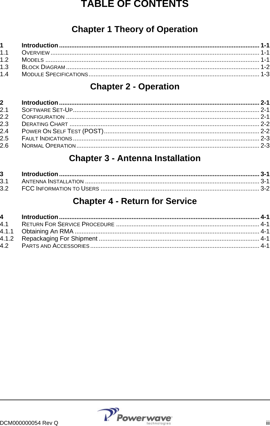
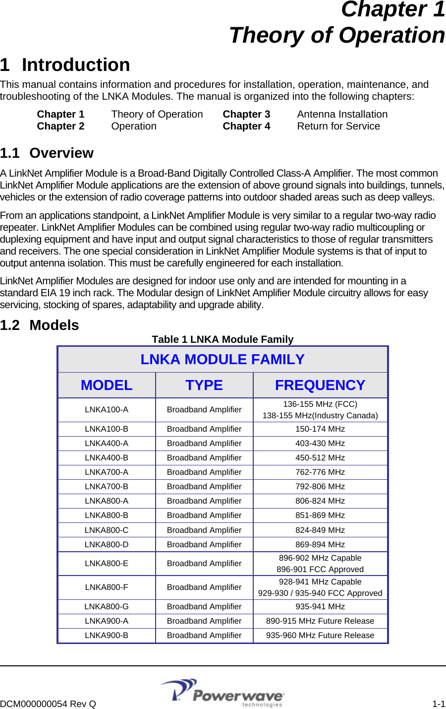
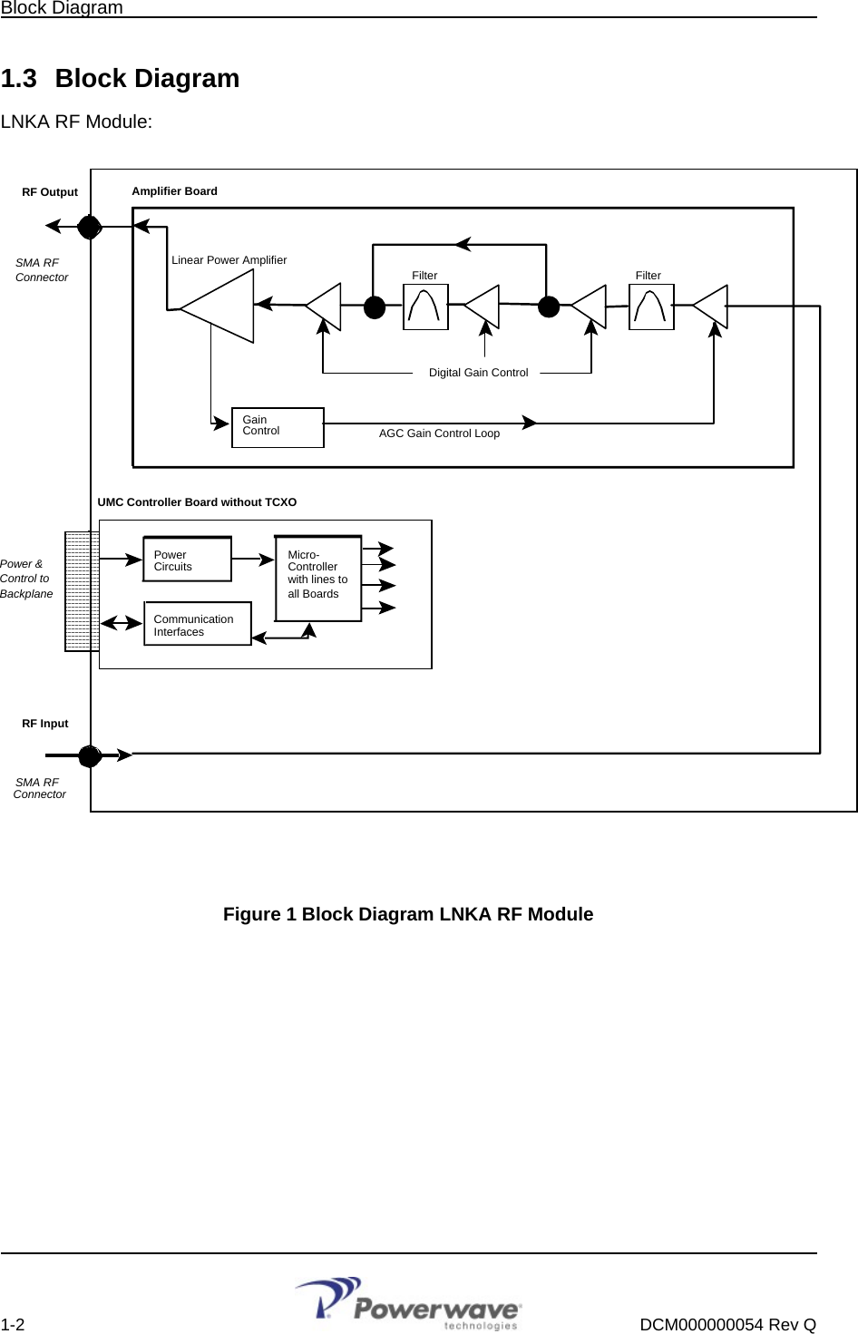
- 1. users manual
- 2. antenna warning statement
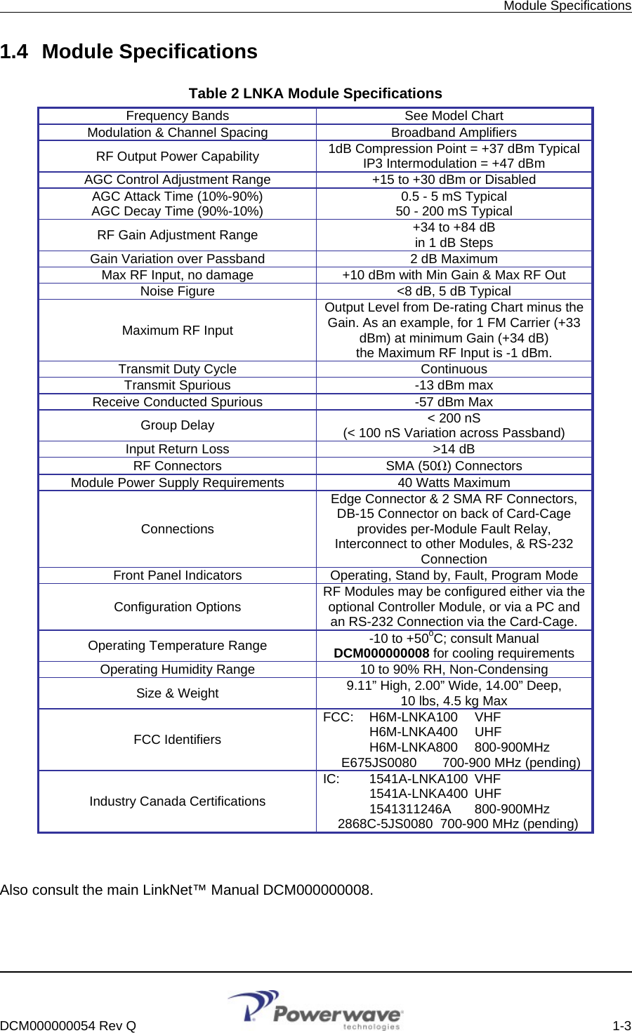
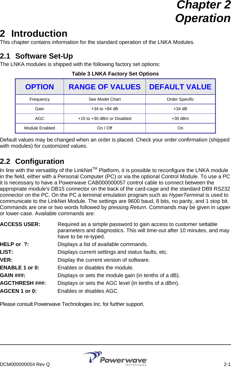
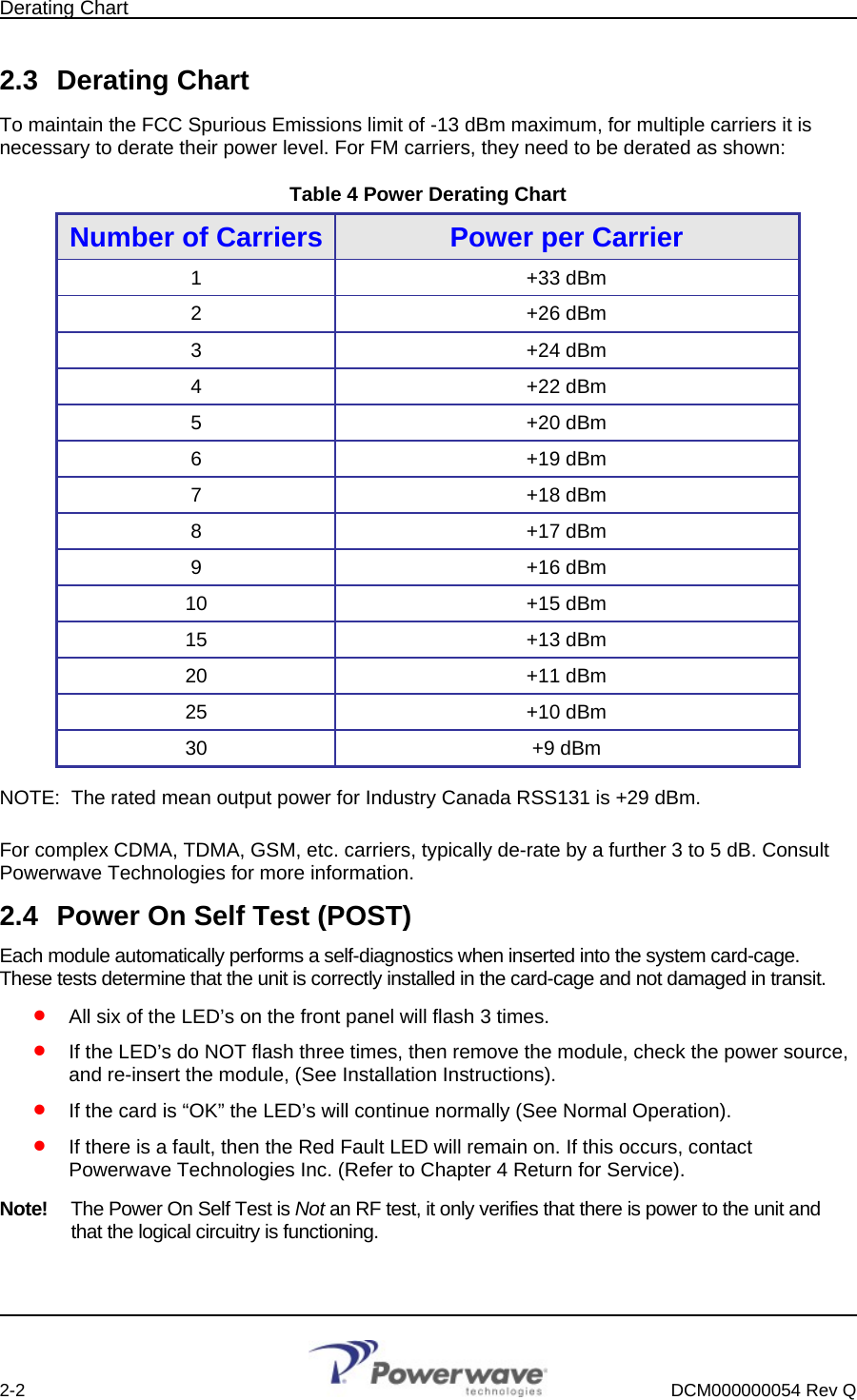
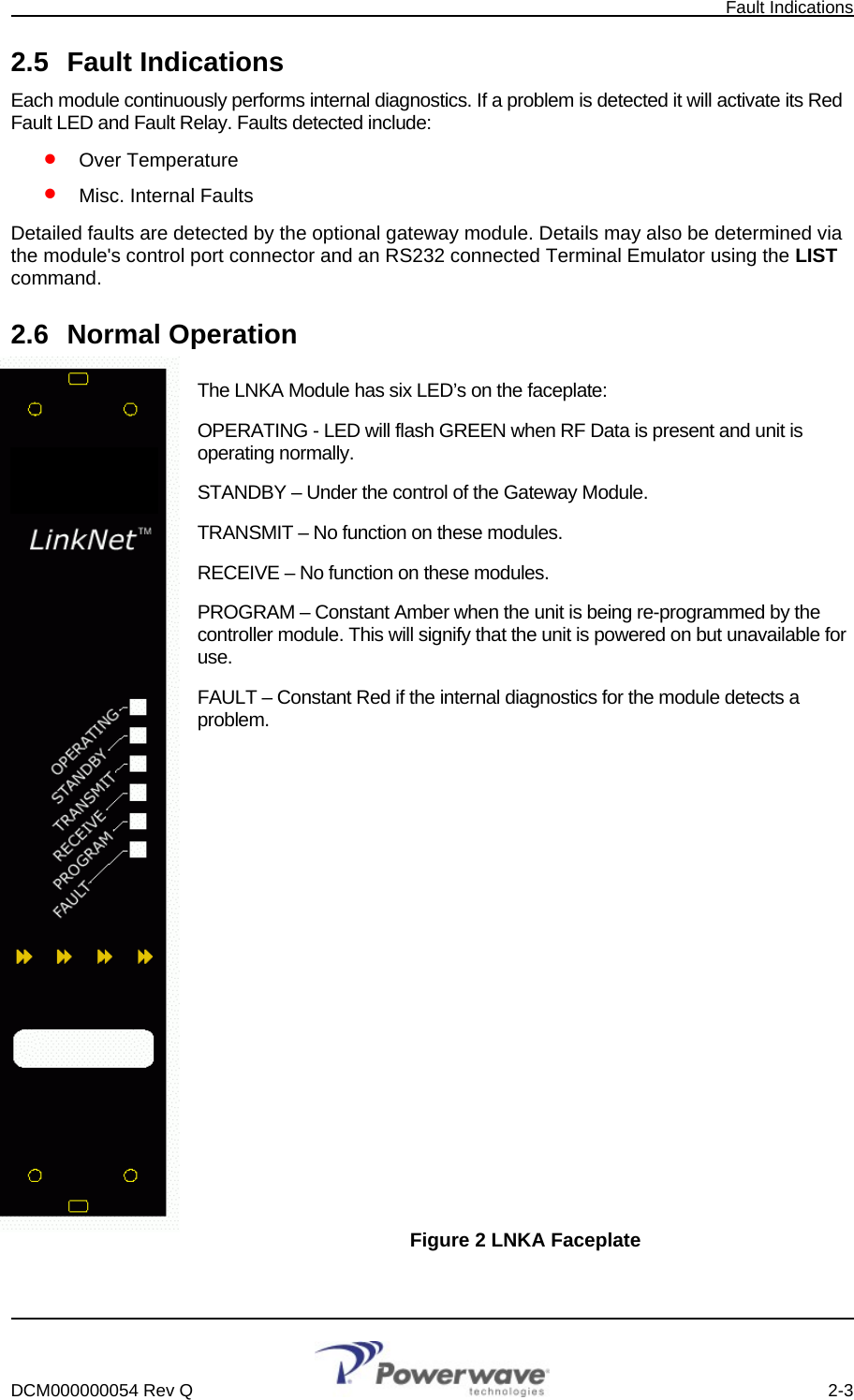
users manual