Powerwave Technologies 5JS0080 RF Broadband Amplifier Module, Model ASY00116 User Manual users manual
Powerwave Technologies Inc RF Broadband Amplifier Module, Model ASY00116 users manual
Contents
- 1. users manual
- 2. antenna warning statement
users manual
DCM000000054 Rev Q
October 2005
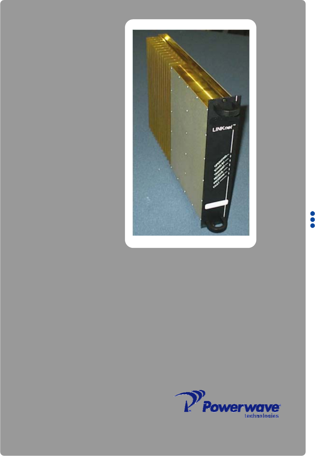
LinkNet™ LNKA100, LNKF400,
LNKA800 RF BROADBAND
AMPLIFIER MODULES
User, Installation, Operation,
and Maintenance Manual

© 2005 Powerwave Technologies Incorporated. All rights reserved.
Powerwave Technologies, and the Powerwave logo are registered trademarks.
This Powerwave product is intended only for installation in a RESTRICTED
ACCESS LOCATION and is designed to operate within the Normal Operating
(typical operating) ranges or conditions specified in this document. Operation of
this equipment beyond the specified ranges in this document may cause:
1. Spurious emissions that violate regulatory requirements.
2. The equipment to be automatically removed from service when maximum
thresholds are exceeded.
3. The equipment to not perform in accordance with its specifications.
It is the Operator's responsibility to ensure this equipment is properly installed and
operated within Powerwave operating specifications to obtain proper performance from
the equipment and to comply with regulatory requirements.
Warnings, Cautions, and Notes
Warnings, Cautions, and Notes
Warnings, cautions, and notes are found throughout this manual where applicable. The
associated icons are used to quickly identify a potential condition that could result in the
consequences described below if precautions are not taken. Notes clarify and provide additional
information to assist the user.
Warning This warning symbol means danger. You are in a situation that could
cause bodily injury. Before you work on any equipment, be aware of the
hazards involved with electrical and RF circuitry and be familiar with
standard practices for preventing accidents.
Caution This caution symbol means reader be careful. In this situation, the user
might do something that could result in equipment damage or loss of
data.
Note This note symbol means reader take note. Notes contain helpful
suggestions or references to material not covered in the document.
Procedures are not contained in notes.
DCM000000054 Rev Q i
Revision Record
ii DCM000000054 Rev Q
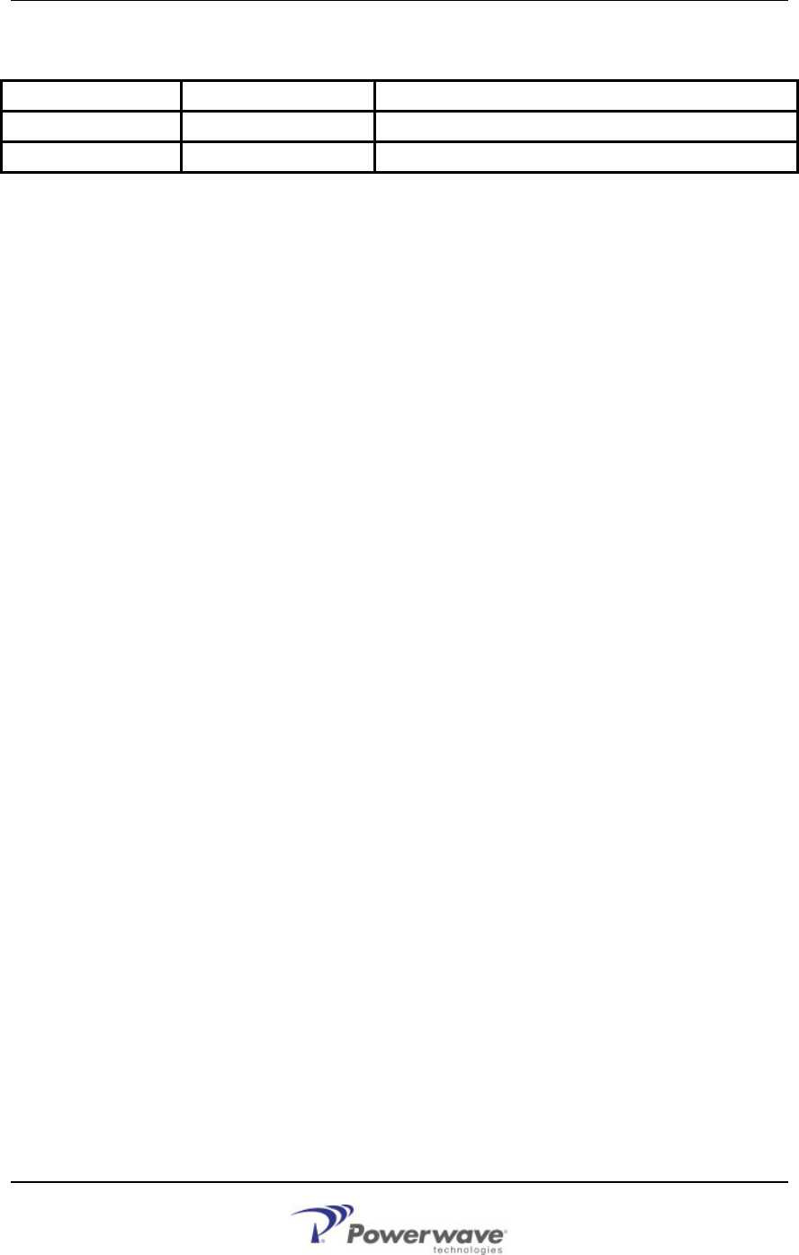
Revision Record
Revision Letter Date of Change Reason for Change
Q October 2005 Added 700 MHz models, misc. corrections
P July 2005 Converted Kaval Rev 14 to Powerwave Format

DCM000000054 Rev Q iii
TABLE OF CONTENTS
Chapter 1 Theory of Operation
1 Introduction.................................................................................................................... 1-1
1.1 OVERVIEW ......................................................................................................................... 1-1
1.2 MODELS ............................................................................................................................ 1-1
1.3 BLOCK DIAGRAM ................................................................................................................ 1-2
1.4 MODULE SPECIFICATIONS................................................................................................... 1-3
Chapter 2 - Operation
2 Introduction.................................................................................................................... 2-1
2.1 SOFTWARE SET-UP............................................................................................................ 2-1
2.2 CONFIGURATION ................................................................................................................ 2-1
2.3 DERATING CHART .............................................................................................................. 2-2
2.4 POWER ON SELF TEST (POST).......................................................................................... 2-2
2.5 FAULT INDICATIONS ............................................................................................................ 2-3
2.6 NORMAL OPERATION.......................................................................................................... 2-3
Chapter 3 - Antenna Installation
3 Introduction.................................................................................................................... 3-1
3.1 ANTENNA INSTALLATION ..................................................................................................... 3-1
3.2 FCC INFORMATION TO USERS ............................................................................................ 3-2
Chapter 4 - Return for Service
4 Introduction.................................................................................................................... 4-1
4.1 RETURN FOR SERVICE PROCEDURE ................................................................................... 4-1
4.1.1 Obtaining An RMA ........................................................................................................... 4-1
4.1.2 Repackaging For Shipment ............................................................................................. 4-1
4.2 PARTS AND ACCESSORIES .................................................................................................. 4-1

Table of Figures
iv DCM000000054 Rev Q
TABLE OF FIGURES
Figure 1 Block Diagram LNKA RF Module................................................................................... 1-2
Figure 2 LNKA Faceplate ............................................................................................................. 2-3
TABLE OF TABLES
Table 1 LNKA Module Family....................................................................................................... 1-1
Table 2 LNKA Module Specifications........................................................................................... 1-3
Table 3 LNKA Factory Set Options .............................................................................................. 2-1
DCM000000054 Rev Q 1-1
Chapter 1
Theory of Operation
1 Introduction
This manual contains information and procedures for installation, operation, maintenance, and
troubleshooting of the LNKA Modules. The manual is organized into the following chapters:
Chapter 1 Theory of Operation Chapter 3 Antenna Installation
Chapter 2 Operation Chapter 4 Return for Service
1.1 Overview
A LinkNet Amplifier Module is a Broad-Band Digitally Controlled Class-A Amplifier. The most common
LinkNet Amplifier Module applications are the extension of above ground signals into buildings, tunnels,
vehicles or the extension of radio coverage patterns into outdoor shaded areas such as deep valleys.
From an applications standpoint, a LinkNet Amplifier Module is very similar to a regular two-way radio
repeater. LinkNet Amplifier Modules can be combined using regular two-way radio multicoupling or
duplexing equipment and have input and output signal characteristics to those of regular transmitters
and receivers. The one special consideration in LinkNet Amplifier Module systems is that of input to
output antenna isolation. This must be carefully engineered for each installation.
LinkNet Amplifier Modules are designed for indoor use only and are intended for mounting in a
standard EIA 19 inch rack. The Modular design of LinkNet Amplifier Module circuitry allows for easy
servicing, stocking of spares, adaptability and upgrade ability.
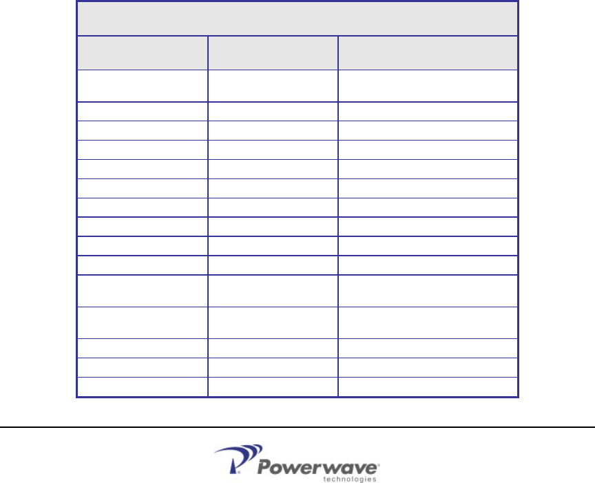
1.2 Models Table 1 LNKA Module Family
LNKA MODULE FAMILY
MODEL TYPE FREQUENCY
LNKA100-A Broadband Amplifier 136-155 MHz (FCC)
138-155 MHz(Industry Canada)
LNKA100-B Broadband Amplifier 150-174 MHz
LNKA400-A Broadband Amplifier 403-430 MHz
LNKA400-B Broadband Amplifier 450-512 MHz
LNKA700-A Broadband Amplifier 762-776 MHz
LNKA700-B Broadband Amplifier 792-806 MHz
LNKA800-A Broadband Amplifier 806-824 MHz
LNKA800-B Broadband Amplifier 851-869 MHz
LNKA800-C Broadband Amplifier 824-849 MHz
LNKA800-D Broadband Amplifier 869-894 MHz
LNKA800-E Broadband Amplifier 896-902 MHz Capable
896-901 FCC Approved
LNKA800-F Broadband Amplifier 928-941 MHz Capable
929-930 / 935-940 FCC Approved
LNKA800-G Broadband Amplifier 935-941 MHz
LNKA900-A Broadband Amplifier
890-915 MHz Future Release
LNKA900-B Broadband Amplifier
935-960 MHz Future Release
Block Diagram
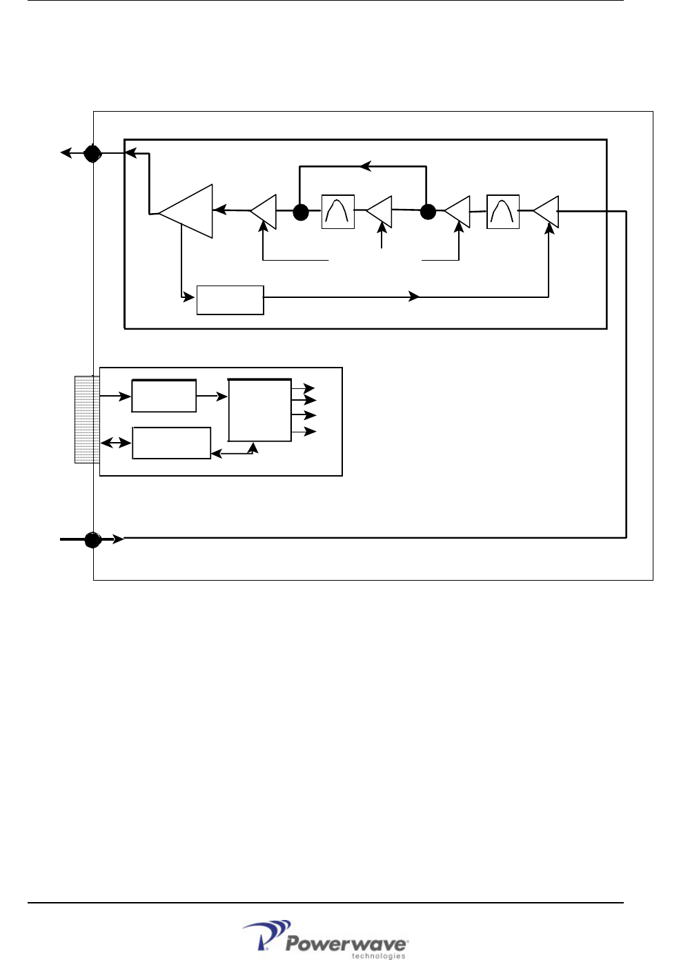
1.3 Block Diagram
LNKA RF Module:
1-2 DCM000000054 Rev Q
Amplifier Board
UMC Controller Board without TCXO
RF Input
RF Output
Micro-
Controller
with lines to
all Boards
SMA RF
Connector
SMA RF
Connector
Power &
Control to
Backplane
Filter
Linear Power Amplifier
Figure 1 Block Diagram LNKA RF Module
AGC Gain Control Loop
Communication
Interfaces
Gain
Control
Power
Circuits
Filter
Digital Gain Control
Module Specifications
DCM000000054 Rev Q 1-3
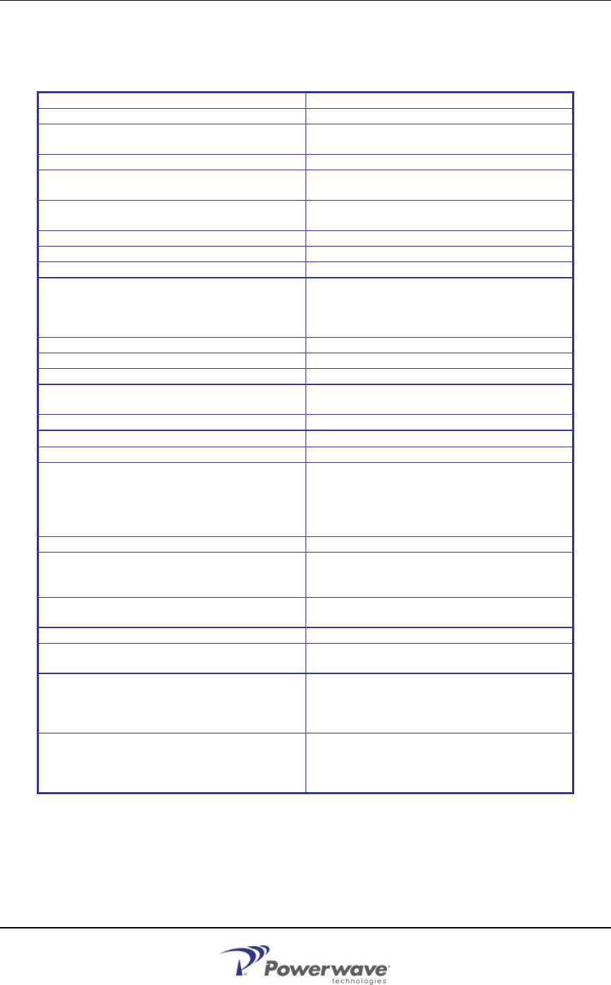
1.4 Module Specifications
Table 2 LNKA Module Specifications
Frequency Bands See Model Chart
Modulation & Channel Spacing Broadband Amplifiers
RF Output Power Capability 1dB Compression Point = +37 dBm Typical
IP3 Intermodulation = +47 dBm
AGC Control Adjustment Range +15 to +30 dBm or Disabled
AGC Attack Time (10%-90%)
AGC Decay Time (90%-10%) 0.5 - 5 mS Typical
50 - 200 mS Typical
RF Gain Adjustment Range +34 to +84 dB
in 1 dB Steps
Gain Variation over Passband 2 dB Maximum
Max RF Input, no damage +10 dBm with Min Gain & Max RF Out
Noise Figure <8 dB, 5 dB Typical
Maximum RF Input
Output Level from De-rating Chart minus the
Gain. As an example, for 1 FM Carrier (+33
dBm) at minimum Gain (+34 dB)
the Maximum RF Input is -1 dBm.
Transmit Duty Cycle Continuous
Transmit Spurious -13 dBm max
Receive Conducted Spurious -57 dBm Max
Group Delay < 200 nS
(< 100 nS Variation across Passband)
Input Return Loss >14 dB
RF Connectors SMA (50Ω) Connectors
Module Power Supply Requirements 40 Watts Maximum
Connections
Edge Connector & 2 SMA RF Connectors,
DB-15 Connector on back of Card-Cage
provides per-Module Fault Relay,
Interconnect to other Modules, & RS-232
Connection
Front Panel Indicators Operating, Stand by, Fault, Program Mode
Configuration Options RF Modules may be configured either via the
optional Controller Module, or via a PC and
an RS-232 Connection via the Card-Cage.
Operating Temperature Range -10 to +50oC; consult Manual
DCM000000008 for cooling requirements
Operating Humidity Range 10 to 90% RH, Non-Condensing
Size & Weight 9.11” High, 2.00” Wide, 14.00” Deep,
10 lbs, 4.5 kg Max
FCC Identifiers
FCC: H6M-LNKA100 VHF
H6M-LNKA400 UHF
H6M-LNKA800 800-900MHz
E675JS0080 700-900 MHz (pending)
Industry Canada Certifications
IC: 1541A-LNKA100 VHF
1541A-LNKA400 UHF
1541311246A 800-900MHz
2868C-5JS0080 700-900 MHz (pending)
Also consult the main LinkNet™ Manual DCM000000008.

1-4 DCM000000054 Rev Q
(This page intentionally left blank)

DCM000000054 Rev Q 2-1
Chapter 2
Operation
2 Introduction
This chapter contains information for the standard operation of the LNKA Modules.
2.1 Software Set-Up
The LNKA modules is shipped with the following factory set options:
Table 3 LNKA Factory Set Options
OPTION RANGE OF VALUES DEFAULT VALUE
Frequency See Model Chart Order Specific
Gain +34 to +84 dB +34 dB
AGC +15 to +30 dBm or Disabled +30 dBm
Module Enabled On / Off On
Default values may be changed when an order is placed. Check your order confirmation (shipped
with modules) for customized values.
2.2 Configuration
In line with the versatility of the LinkNetTM Platform, it is possible to reconfigure the LNKA module
in the field, either with a Personal Computer (PC) or via the optional Control Module. To use a PC
it is necessary to have a Powerwave CAB000000057 control cable to connect between the
appropriate module's DB15 connector on the back of the card-cage and the standard DB9 RS232
connector on the PC. On the PC a terminal emulation program such as HyperTerminal is used to
communicate to the LinkNet Module. The settings are 9600 baud, 8 bits, no parity, and 1 stop bit.
Commands are one or two words followed by pressing Return. Commands may be given in upper
or lower-case. Available commands are:
ACCESS USER: Required as a simple password to gain access to customer settable
parameters and diagnostics. This will time-out after 10 minutes, and may
have to be re-typed.
HELP or ?: Displays a list of available commands.
LIST: Displays current settings and status faults, etc.
VER: Display the current version of software.
ENABLE 1 or 0: Enables or disables the module.
GAIN ###: Displays or sets the module gain (in tenths of a dB).
AGCTHRESH ###: Displays or sets the AGC level (in tenths of a dBm).
AGCEN 1 or 0: Enables or disables AGC.
Please consult Powerwave Technologies Inc. for further support.

Derating Chart
2-2 DCM000000054 Rev Q
2.3 Derating Chart
To maintain the FCC Spurious Emissions limit of -13 dBm maximum, for multiple carriers it is
necessary to derate their power level. For FM carriers, they need to be derated as shown:
Table 4 Power Derating Chart
Number of Carriers Power per Carrier
1 +33 dBm
2 +26 dBm
3 +24 dBm
4 +22 dBm
5 +20 dBm
6 +19 dBm
7 +18 dBm
8 +17 dBm
9 +16 dBm
10 +15 dBm
15 +13 dBm
20 +11 dBm
25 +10 dBm
30 +9 dBm
NOTE: The rated mean output power for Industry Canada RSS131 is +29 dBm.
For complex CDMA, TDMA, GSM, etc. carriers, typically de-rate by a further 3 to 5 dB. Consult
Powerwave Technologies for more information.
2.4 Power On Self Test (POST)
Each module automatically performs a self-diagnostics when inserted into the system card-cage.
These tests determine that the unit is correctly installed in the card-cage and not damaged in transit.
•
•
•
•
All six of the LED’s on the front panel will flash 3 times.
If the LED’s do NOT flash three times, then remove the module, check the power source,
and re-insert the module, (See Installation Instructions).
If the card is “OK” the LED’s will continue normally (See Normal Operation).
If there is a fault, then the Red Fault LED will remain on. If this occurs, contact
Powerwave Technologies Inc. (Refer to Chapter 4 Return for Service).
Note! The Power On Self Test is Not an RF test, it only verifies that there is power to the unit and
that the logical circuitry is functioning.
Fault Indications
2.5 Fault Indications
Each module continuously performs internal diagnostics. If a problem is detected it will activate its Red
Fault LED and Fault Relay. Faults detected include:
•
•
Over Temperature
Misc. Internal Faults
Detailed faults are detected by the optional gateway module. Details may also be determined via
the module's control port connector and an RS232 connected Terminal Emulator using the LIST
command.
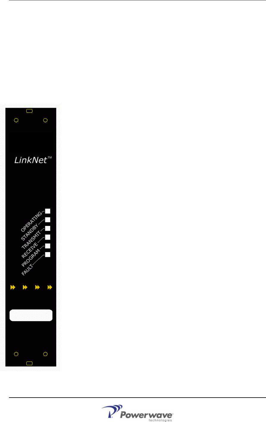
2.6 Normal Operation
The LNKA Module has six LED’s on the faceplate:
OPERATING - LED will flash GREEN when RF Data is present and unit is
operating normally.
STANDBY – Under the control of the Gateway Module.
TRANSMIT – No function on these modules.
RECEIVE – No function on these modules.
PROGRAM – Constant Amber when the unit is being re-programmed by the
controller module. This will signify that the unit is powered on but unavailable for
use.
FAULT – Constant Red if the internal diagnostics for the module detects a
problem.
Figure 2 LNKA Faceplate
DCM000000054 Rev Q 2-3

2-4 DCM000000054 Rev Q
(This page intentionally left blank)

DCM000000054 Rev Q 3-1
Chapter 3
Antenna Installation
3 Introduction
This chapter contains antenna installation and warning information for the LNKA Modules.
3.1 Antenna Installation
•
•
•
•
•
•
All antenna installation to be performed by qualified technical personnel only.
Antenna installation instructions and locations below are for the purpose of satisfying
FCC RF Exposure Compliance requirements.
Note! If multiple LinkNet™ Modules are used, the Instructions below apply to the
composite power output of all Modules when transmitting simultaneously.
The Roof Top Antenna or Antennae for linking to the Donor Site(s) is/are directional (high
gain) Antennae, fixed-mounted physically on the side or top of a building, or on a tower.
The Antenna Gain must be no more than 20 dBi.
Note! If multiple LinkNet™ Modules are used with output combiners into any one
Antenna, and/or multiple Antennae are used on one Roof Top, then the sum of
composite powers into all Roof Top Antennae must not exceed 20 Watts maximum.
The Roof Top Antennae location should be such that only qualified technical personnel
can access it, and that under normal operating conditions no other person can touch the
antenna, or approach within 10 meters of the antenna.
For the Cellular Uplink Band (824-849 MHz) the Roof Top Antenna or Antennae for
linking to the Donor Site(s) has the added restriction that the Effective Radiated Power
(ERP) must not exceed 7 Watts (+38 dBm). Thus, if the AGC is set (as per the Carrier
Derating Chart) to +28 dBm as an example, the maximum allowed antenna gain must be
no more than 10 dBi.
The In-Building Antenna connection is via a coaxial cable distribution system with signal
taps at various points connected to the fixed-mounted Indoor Antennae. The Indoor
Antennae are simple 1/4 wavelength (0 dB Gain) types. They are used with Powerwave
Technologies’ 12, 16, or 20 dB cable taps. As such the maximum EIRP will be at the first
tapped antenna, which will be 12 dB below the maximum signal level of the LinkNet™
(+40 dBm); +28 dBm, or 0.63 Watts EIRP. These antennae are to be installed such that
no person can touch the antenna, or approach within 0.2 Meters.
Note! If multiple LinkNet™ Modules are used with output combiners, then the composite
power output of all Modules transmitting simultaneously must meet this maximum
EIRP requirement.
Please consult Powerwave Technologies Inc. for assistance as required.
FCC Information to Users
ANTENNA INSTALLATION
CAUTION
ALL ANTENNA INSTALLATION IS TO BE PERFORMED BY QUALIFIED TECHNICAL
PERSONNEL ONLY.
ANTENNA INSTALLATION INSTRUCTIONS AND LOCATIONS ARE FOR THE PURPOSE
OF SATISFYING FCC RF EXPOSURE COMPLIANCE REQUIREMENTS, AND ARE NOT
OPTIONAL.
ALL ROOF TOP ANTENNA INSTALLATION MUST BE SUCH THAT NO PERSON CAN
TOUCH THE ANTENNA, OR APPROACH CLOSER THAN 10 METERS.
ALL IN-BUILDING ANTENNAE INSTALLATIONS MUST BE SUCH THAT NO PERSON CAN
TOUCH THE ANTENNAE, OR APPROACH CLOSER THAN 0.2 METERS.
3.2 FCC Information to Users
• This equipment has been tested and found to comply with the limits for a Class A digital
device, pursuant to Part 15 of the FCC Rules. These limits are designed to provide
reasonable protection against harmful interference when the equipment is operated in a
commercial environment. This equipment generates, uses, and can radiate radio
frequency energy and, if not installed and used in accordance with the instruction manual,
may cause harmful interference to radio communications. Operation of this equipment in
a residential area is likely to cause harmful interference in which case the user will be
required to correct the interference at his own expense.
CAUTION
CHANGES OR MODIFICATIONS NOT EXPRESSLY APPROVED BY POWERWAVE
TECHNOLOGIES INC. COULD VOID THE USER’S AUTHORITY TO OPERATE THE
EQUIPMENT.
3-2 DCM000000054 Rev Q

DCM000000054 Rev Q 4-1
Chapter 4
Return for Service
4 Introduction
This chapter contains return for service and parts and accessories information for the LNKA Modules.
4.1 Return For Service Procedure
When returning products to Powerwave Technologies Inc., the following procedures will ensure
optimum response.
4.1.1 Obtaining An RMA
A Return Material Authorization (RMA) number must be obtained prior to returning equipment to the
factor for service. Please contact our Repair Department at +1 (714) 466-1000 to obtain this number, or
FAX your request to +1 (714) 466-5816 or mailto:RMA@PWAV.COM. Failure to obtain this RMA
number may result in delays in receiving repair service.
4.1.2 Repackaging For Shipment
To ensure safe shipment of the amplifier, it is recommended that the original package designed for
shipping the amplifier be reused. If it is not available, contact Powerwave Technologies Inc. Customer
Service Department for packing materials.
4.2 Parts and Accessories
Parts and Accessories for the LNKA Modules may be purchased by contacting Powerwave
Technologies Inc. at 1-888-PWR-WAVE. When ordering a replacement part, please provide model
number, serial number and software version number.