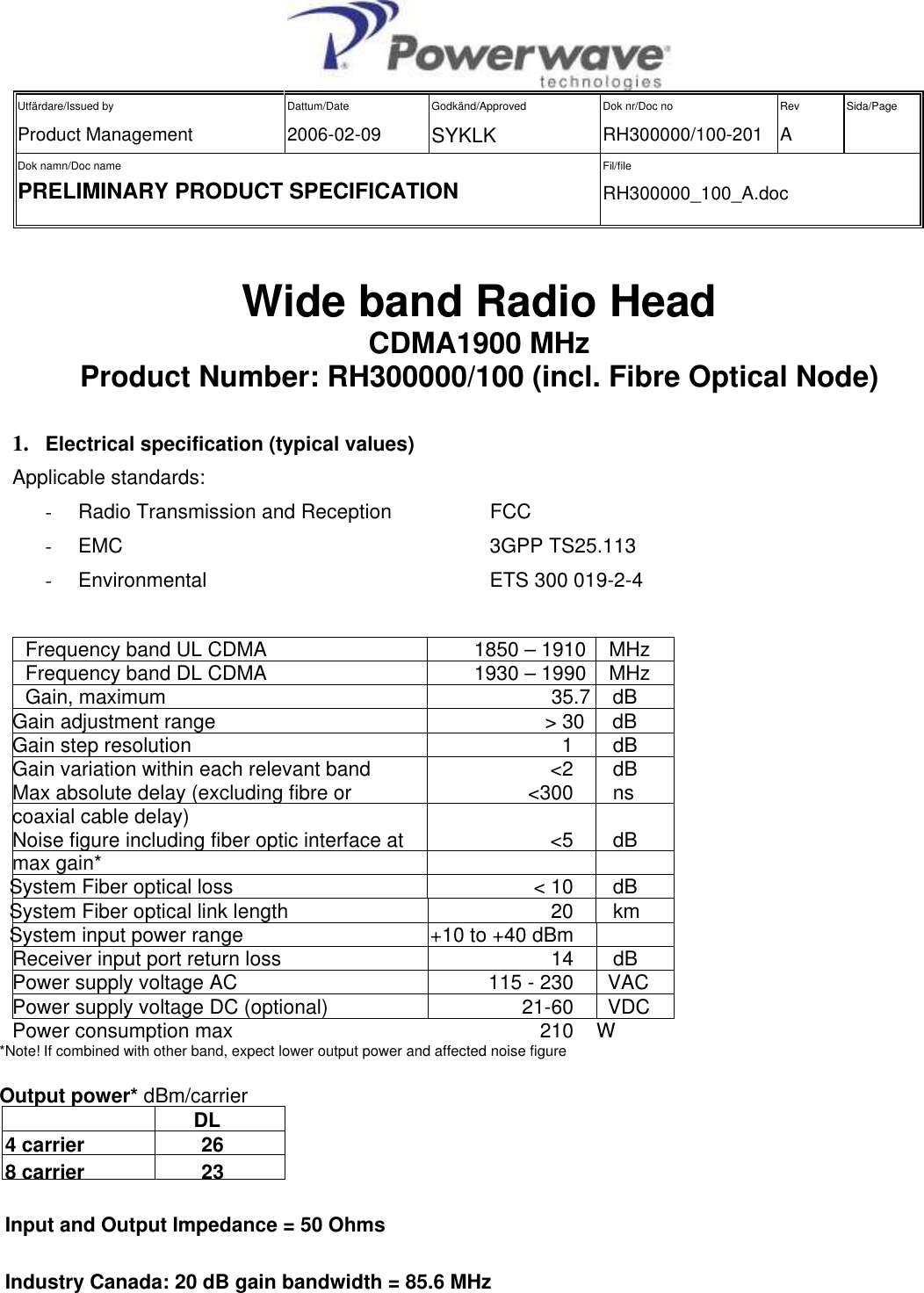
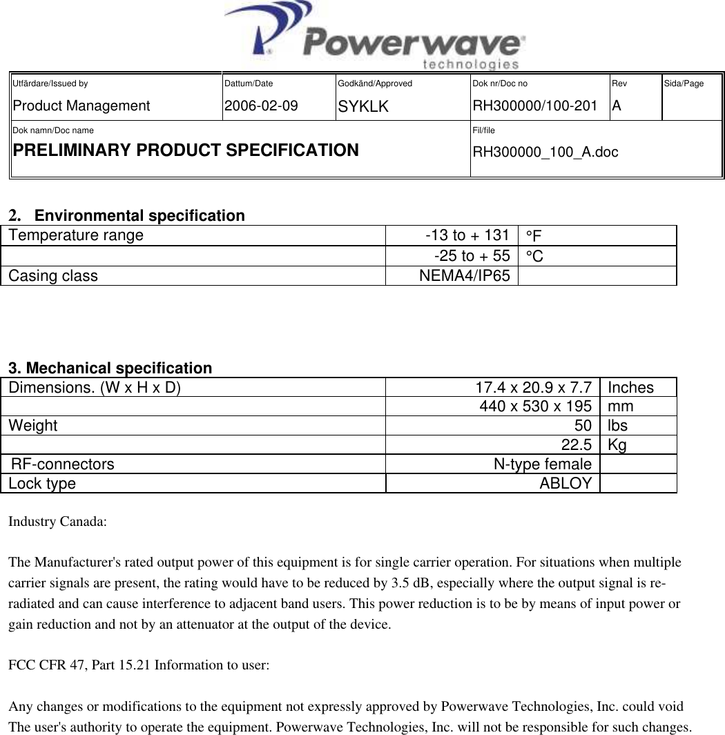
Powerwave Technologies 5JS0084 Fiber-Fed Repeater/Radio Head User Manual RH300000 100 A

Powerwave Technologies Inc Fiber-Fed Repeater/Radio Head RH300000 100 A

Contents

User Manual 1

 Utfärdare/Issued by Product Management Dattum/Date 2006-02-09 Godkänd/Approved SYKLK Dok nr/Doc no RH300000/100-201 Rev A Sida/Page   Dok namn/Doc name PRELIMINARY PRODUCT SPECIFICATION  Fil/file RH300000_100_A.doc      Wide band Radio Head CDMA1900 MHz Product Number: RH300000/100 (incl. Fibre Optical Node)   1. Electrical specification (typical values) Applicable standards: -  Radio Transmission and Reception  FCC  -  EMC        3GPP TS25.113 -  Environmental         ETS 300 019-2-4    Frequency band UL CDMA  1850 – 1910  MHz Frequency band DL CDMA  1930 – 1990  MHz Gain, maximum                                                                     35.7    dB Gain adjustment range                                                           > 30     dB Gain step resolution  1     dB Gain variation within each relevant band  <2     dB Max absolute delay (excluding fibre or coaxial cable delay)  <300     ns Noise figure including fiber optic interface at max gain*  <5     dB System Fiber optical loss  < 10      dB System Fiber optical link length  20      km System input power range  +10 to +40 dBm   Receiver input port return loss  14     dB Power supply voltage AC  115 - 230    VAC Power supply voltage DC (optional)  21-60    VDC Power consumption max  210  W *Note! If combined with other band, expect lower output power and affected noise figure  Output power* dBm/carrier   DL  4 carrier  26  8 carrier  23   Input and Output Impedance = 50 Ohms  Industry Canada: 20 dB gain bandwidth = 85.6 MHz
 Utfärdare/Issued by Product Management Dattum/Date 2006-02-09 Godkänd/Approved SYKLK Dok nr/Doc no RH300000/100-201 Rev A Sida/Page   Dok namn/Doc name PRELIMINARY PRODUCT SPECIFICATION  Fil/file RH300000_100_A.doc      2. Environmental specification Temperature range  -13 to + 131 °F   -25 to + 55  °C Casing class  NEMA4/IP65       3. Mechanical specification Dimensions. (W x H x D)  17.4 x 20.9 x 7.7  Inches        440 x 530 x 195  mm Weight    50  lbs     22.5  Kg RF-connectors  N-type female   Lock type  ABLOY    Industry Canada: The Manufacturer's rated output power of this equipment is for single carrier operation. For situations when multiple carrier signals are present, the rating would have to be reduced by 3.5 dB, especially where the output signal is re-radiated and can cause interference to adjacent band users. This power reduction is to be by means of input power orgain reduction and not by an attenuator at the output of the device. FCC CFR 47, Part 15.21 Information to user: Any changes or modifications to the equipment not expressly approved by Powerwave Technologies, Inc. could voidThe user's authority to operate the equipment. Powerwave Technologies, Inc. will not be responsible for such changes.
Powerwave Fiber Optics PrefaceVM100 56/EN – User’s Manual Rev. P1A9-Draft  2004-11 iUser’s ManualFiber Optics–English
Preface Fiber Optics Powerwaveii Rev. P1A9-Draft  2004-11 VM100 56/EN – User’s ManualThis document contains descriptions of Powerwave fiber optic units. Most sections in the document do not contain comlete information for building, installation, or commissioning systems and are therefore not allowed to be used as any kind of installation or commissioning guide. Only sections specificly declared to be installation or commissioning instructions are allowed to be used for that purpose.Hardware and software mentioned in this document are subjected to continuous development and improvement. Consequently, there may be minor discrepancies between the information in the document and the performance or design of the products. Specifications, dimensions and other statements mentioned in this document are subject to changes without prior notice.Powerwave and its suppliers shall not be liable for any damages related to this product, or for any other damages whatsoever caused of the use of or inability to use any Powerwave product. This is applicable even if Powerwave has been advised of the damage risk. Under any circumstances, Powerwave's entire liability shall be limited to replace such defective software or hardware which was originally purchased from Powerwave.LinDAS is a trademark of Powerwave. Microsoft is a registered trademark of Microsoft Corporation. Windows, Windows 98, Windows NT and Windows 2000 are trademarks of Microsoft Corporation. Intel and Pentium are registered trademarks of Intel Corporation. Hayes is a registered trademark of Hayes Microcomputer Products, Inc. Other trademarks mentioned in this manual are trademarks or registered trademarks of their respective owners.Powerwave Technologies, Inc., 1801 East St. Andrew Place, Santa Ana, CA 92705 USAPhone: +1 714 466 1000 – Fax: +1 714 466 5800 – Internet: www.powerwave.comThis manual or parts of it may not be reproduced without the written permission of Powerwave Technologies. Infringements will be prosecuted. All rights reserved.Copyright © Powerwave Technologies, Inc., CA 92705 USA, 1994 – 2004.
Powerwave Fiber Optics PrefaceVM100 56/EN – User’s Manual Rev. P1A9-Draft  2004-11 iiiContentsAbbreviations .................................................................................................................................. v1. Safety ......................................................................................................................................... 1-1Human Exposure of RF Radiation  ..................................................................................... 1-3Repeater Antennas  ........................................................................................................ 1-3Installation and Maintenance of Antenna Systems ....................................................... 1-3Radiation Exposure ....................................................................................................... 1-4Radiation Safety Distances  ........................................................................................... 1-4Static Electricity ................................................................................................................. 1-62. Introduction  ............................................................................................................................... 2-1Fiber Optics in General  ...................................................................................................... 2-2Fiber Optic Transmission Versus Electrical Transmission ........................................... 2-3Duplex Transmission  .................................................................................................... 2-4System Building Blocks ..................................................................................................... 2-5FON, Fiber Optic Node ................................................................................................. 2-6FOU, Fiber Optic Unit  .................................................................................................. 2-6BMU, Base Station Master Unit  ................................................................................... 2-7RMU, Repeater Master Unit  ......................................................................................... 2-7FOR, Fiber Optic Repeater  ........................................................................................... 2-7OCM, Optical Converter Module  ................................................................................. 2-8RH, Remote Hub ........................................................................................................... 2-93. FON, Fiber Optic Node ............................................................................................................. 3-1Functional Description ....................................................................................................... 3-1Block Diagram  .............................................................................................................. 3-2R2R Communication  .................................................................................................... 3-4Gateway Node ............................................................................................................... 3-5Alarm ............................................................................................................................ 3-5Power ............................................................................................................................ 3-5Backup Power  ............................................................................................................... 3-5Design ................................................................................................................................ 3-6The FON Board ............................................................................................................. 3-6Indicators ....................................................................................................................... 3-6RF and Optical Ports ..................................................................................................... 3-8Connection Ports ........................................................................................................... 3-9Operational Control ............................................................................................................ 3-114. RF Over Fiber  ........................................................................................................................... 4-1The RF Modulated Signal Paths  ........................................................................................ 4-2Downlink RF Signal Path  ............................................................................................. 4-3Uplink RF Signal Path  .................................................................................................. 4-8FOU, Fiber Optic Unit  .................................................................................................. 4-10Noise, Intermodulation and Dynamic Signal Range ..................................................... 4-11Simplex Transmission ........................................................................................................ 4-12Duplex Transmission  ......................................................................................................... 4-13
Preface Fiber Optics Powerwaveiv Rev. P1A9-Draft  2004-11 VM100 56/EN – User’s Manual5. IP Over Fiber  ............................................................................................................................  5-1IP Network Terminology ...................................................................................................  5-2Requirements .....................................................................................................................  5-3F-Net Characteristics  .........................................................................................................  5-4Node Units .........................................................................................................................  5-5The FON Unit Net Interfaces  .......................................................................................  5-6Network Example ..............................................................................................................  5-76. Commissioning  .........................................................................................................................  6-1Equipment Required  ..........................................................................................................  6-1Commissioning the Fiber Optic System ............................................................................  6-2Master Unit Downlink Path ..........................................................................................  6-2Slave Units  ...................................................................................................................  6-3System Configuration Examples  .......................................................................................  6-67. Passive Devices  ........................................................................................................................  7-1OSP, Optical Splitter  .........................................................................................................  7-2Graphic Symbol ............................................................................................................  7-3Examples ......................................................................................................................  7-3WDM, Wavelength Division Multiplexer  .........................................................................  7-4Graphic Symbol ............................................................................................................  7-5Example ........................................................................................................................ 7-5Fiber Optic Cables  ............................................................................................................. 7-6Powerwave Patch Cables ..............................................................................................  7-8Fiber Optic Connectors ......................................................................................................  7-9Connector Types ...........................................................................................................  7-10Handling Connectors  ....................................................................................................  7-118. Troubleshooting ........................................................................................................................  8-1Index ............................................................................................................................................... I-1Questionnaire ..............................................................................................................................  Q-1
Powerwave Fiber Optics PrefaceVM100 56/EN – User’s Manual Rev. P1A9-Draft  2004-11 vAbbreviationsAbbreviations used in the document, in the software and in supported hardware:3G Third Generation mobile system.AGC Automatic Gain Control.ALI Alarm Interface (board).ALR Powerwave low power repeater (usually called Compact repeater).ALT Powerwave low power train repeater.AMPS Advanced Mobile Phone Service.AR Powerwave repeater (usually called standard repeater).BCCH Broadcast Control Channel.BMU Base station Master Unit.BA Booster Amplifier.BS Base Station.BSA Band Selective Amplifier (board).BSC Band Selective Compact repeater (board).BSel Band Selective repeater.BTS Base station Transceiver System.CDMA Code Division Multiple Access.CH Central Hub.CHA Channel Amplifier (board).CMB CombinerCSA CDMA/WCDMA Segment Amplifier (board).CSel Channel Selective repeater.CU Control Unit (board).CW Continuous Wave.DAMPS Digital Advanced Mobile Phone Service.DAS Distributed Antenna System.DC Directional Coupler.DCS Digital Communication System (same as PCN).DFB Distributed Feedback.DIA Distribution (board).DIF Diplex Filter.DL Downlink (signal direction from base station, via repeater, to mobile station).DNS Domain Name Server.DMB Digital Multimedia Broadcasting.DPX Duplex filter.EEPROM Electrical Erasable Programmable Read Only Memory.EGSM Extended Global System for Mobile communication.ETACS Extended Total Access Communication System.ETS European Telecommunications Standards.F2F Fiber to Fiber link (renamed to F-link/FLI).FCC Federal Communications Commission.FLI Fiber Link Interface.F-link Fiber link.F-net Fiber network.FON Fiber Optic Node.FOR Fiber Optic Repeater.FOT Fiber Optic Transceiver.FOU Fiber Optic Unit.GSM Global System for Mobile communication.GPS Global Position System.HW HardwareICMP Internet Control Message Protocol.IM Intermodulation.IP Internet Protocol.LAN Local Area Network.LED Light Emitting Diode.
Preface Fiber Optics Powerwavevi Rev. P1A9-Draft  2004-11 VM100 56/EN – User’s ManualLinDAS Light Indoor Distributed Antenna System.LNA Low Noise Amplifier (unit).MACID Physical address to RIA or CU board (comparable with Ethernet card MACID).MRX Measurement Receiver (board).MS Mobile Station.MSC Mobile Switching Center.NAPT Network Address and Port Translation.NMT Nordic Mobile Telephone (system).NS Name Server.OCM Optical Converter Module.OM-Online Operation and Maintenance Online.OMS Operation and Maintenance System.OMT16 Operation and Maintenance Terminal (replaced with OMT32).OMT32 Operation and Maintenance Terminal (replaced with OM-Online).OSP Optical Splitter.PA Power Amplifier (board).PEP Peak Envelope Power.PCN Personal Communication Network (same as DCS).PCS Personal Communication System.PPP Point to Point Protocol.PSM Power Supply Module.PSTN Public Switched Telephone Network.PSU Power Supply Unit.PTFE Polytetrafluoro Ethylene (Teflon).R2R Repeater to Repeater (Powerwave specific network).R2R net R2R network.RAS Remote Access Service.RCC Remote Communication Control (unit).RCM RF Combiner Module.RCU Remote Control Unit.RF Radio Frequency.RH Remote Hub.RIA Repeater Interface Adapter (board).RMS Root Mean Square.RMU Repeater Master Unit.RSSI Received Signal Strength Indication.RTC Real Time Clock.RX ReceiverSLW Sliding Window (Powerwave specific protocol).SW SoftwareTACS Total Access Communication System.TDMA Time Division Multiple Access.TX TransmitterUDP User Datagram Protocol.UL Uplink (signal direction from mobile station via repeater to base station).UPS Uninterruptible Power Supply.VAC Voltage Alternating Current.VDC Voltage Direct Current.WAN Wide Area Network.WBA Wideband Amplifier (board).WCDMA Wideband Code Division Multiple Access.WCS Wideband Coverage System.WDM Wavelength Division Multiplexer.WLI Wire Link Interface.W-link Wire link.W-net Wire network.WRH Wideband Radio Head.
Powerwave Fiber OpticsVM100 56/EN – User’s Manual Rev. P1A9-Draft  2004-11 1 - 11. SafetyIn this chapter, the word ’repeater’ includes all Powerwave repeating units, such as repeaters, hubs and radio heads.It is necessary that any personnel involved in installation, operation or service of units included in an Powerwave repeater system understand and follow the below points.•The Powerwave repeaters are designed to receive and amplify signals from one or more base stations and retransmit the signals to one or more mobile stations. And, also to act the other way round, that is to receive signals from one or more mobile stations, amplify and retransmit the signals to the base stations. Powerwave repeater systems must be used exclusively for this purpose and nothing else.•Units supplied from the mains must be connected to grounded outlets and in conformity with the local prescriptions.•Power supply units supplied from the mains contain dangerous voltage that can cause electric shock. Disconnect the mains prior to any work in such a unit. Local regulations are to be followed when servicing such units.Authorized service personnel only are allowed to service units while the mains is connected.•All RF transmitting units, including repeaters, will generate radio signals and thereby give rise to electromagnetic fields that may be hazardous to the health of any person who is extensively exposed close to an antenna.See the Human Exposure of RF Radiation section on page 1-3.Beryllium oxide•Beryllium oxide (BeO) may be contained in power devices, for instance in dummy loads in directional couplers (DCC), in combiner units (CMB), and in attenuators on the FON board. Beryllium oxide is poisonous if present as dust or smoke that can be inhaled.Do not file, grind, machine, or treat these parts with acid.Hydrogen fluoride     •Coaxial cables used in many Powerwave systems have the insulation made of PTFE, polytetrafluoro ethylene, that gives off small amounts of hydrogen fluoride when heated. Hydrogen fluoride is poisonous. Do not use heating tools when stripping off coaxial cable insulation.No particular measures are to be taken in case of fire because the emitted concentration of hydrogen fluoride is very low.•A lithium battery is permanently mounted in repeater CU units, and in FON and OCM units. Due to the risk of explosion, this battery must only be removed from the board by an Powerwave authorized service technician.•NiCd batteries are mounted on the FON unit. These batteries contain environmental poisonous substances. If replaced, the old batteries should be taken care of as stated in the local prescriptions.
Fiber Optics Powerwave1 - 2 Rev. P1A9-Draft  2004-11 VM100 56/EN – User’s Manual•The FON unit contains a class IIIb laser transmitter that emits 2 – 5mW invisible laser radiation during operation. Avoid direct exposure from unconnected laser transmitter or fiber cord as follows:– Do not power up the FON unit if a fiber cable is not attached to the fiber output UL port, neither if a fiber cable is attached to the port but unattached in the other end.– Never look in the end of a fiber cable. The 1310nm and 1550nm laser light is not visible, so no signal identification can be made anyway. Use always an instrument, such as a power meter to detect signaling.– Never use any kind of magnifying devices that can focus the laser light to an unprotected eye.
Powerwave Fiber OpticsVM100 56/EN – User’s Manual Rev. P1A9-Draft  2004-11 1 - 3Human Exposure of RF RadiationThis section contains a few words about repeater antennas and prescriptions for installaton and maintenance of antenna systems. Also, it describes how to calculate safety distances needed for RF radiation at different antenna power and frequencies.Repeater AntennasTo be able to receive and transmit signals as described in the first bulleted paragraph on page 1-1, a repeater is connected to a donor antenna directed towards the base station, and a service antenna directed towards the coverage area. A fiber optic cable from the base station might, however, be substituted for the donor antenna.Installation and Maintenance of Antenna SystemsInstallation and maintenance of all repeater antenna systems must be performed with respect to the radiation exposure limits for public areas.The antenna radiation level is affected by the repeater output power, the antenna gain, and by transmission devices such as cables, connectors, splitters and feeders.Have also in mind that the system minimum coupling loss, typical between 25dB and 35dB, is determined by a standard with the purpose to protect base stations from noise and other performance dropping effects.
Fiber Optics Powerwave1 - 4 Rev. P1A9-Draft  2004-11 VM100 56/EN – User’s ManualRadiation ExposureWHO, World Health Organization, and ICNIRP, International Commission on Non-Ionising Radiation Protection, have determined recommendations for radiation exposure.ICNIRP recommends not to exceed the following radiation power for public exposure:Frequency Radiation power900MHz 4,5W/m²1800MHz 9,0W/m²2100MHz 10,0W/m²For antennas larger than 20cm the maximum radiation power can be calculated by using the following formula:whereS = Radiation power in W/m².P = Output power in W.r = Distance between antenna and human in meter.To tackle the worst case successfully, the calculation does not consider system power reducing actions, such as  power control and DTX.Figure 1-1 shows the safety distance to an antenna due to the RF radiation. The distance is depending on the antenna output power and frequency, which is illustrated with two graphs in the figure.One of the graphs applies to 4.5W/m2 (900MHz) and the other to 9.0W/m2 (1800MHz) or 10.0W/m2 (2100MHz).The safety distance range in Figure 1-1 is 0 to 1.4 meter that covers an antenna power range of 10dBm to 50dBm (0.01W to 100W).Radiation Safety DistancesThis section illustrates the safety distances to the antennas for some typical repeater configurations.Outdoor GSM 900MHzThe safety distance can be read to 0.75 meter in Figure 1-1 as the maximum radiation power is 4.5W/m² for 900MHz.SP4Sr2uu-------------------=Repeater output power +33dBmFeeder loss –5dBAntenna gain +17dBiEIRP +45dBm
Powerwave Fiber OpticsVM100 56/EN – User’s Manual Rev. P1A9-Draft  2004-11 1 - 5Figure 1-1.  Safety distance to active antennaIndoor GSM 900MHzThe safety distance can be read to 0.035 meter for 4.5W/m² (900MHz).Outdoor UMTS Standard High PowerThe safety distance can be read to 0.9 meter for 10W/m² (2100MHz).Indoor UMTSThe safety distance can be read to 0.035 meter for 10W/m² (2100MHz).101520253035400 0.1 0.2 0.3 0.4 0.5 0.6 0.7 0.8 0.9 1.045501.1 1.2 1.3 1.40.010.030.10.31.03.210.031.6100 4.5W/m2 (900MHz) 9W/m2 (1800MHz) 10W/m2 (2100MHz)Safety distance to antenna in meterAntenna output power in dBmAntenna output power in WRepeater output power +22dBmFeeder loss –5dBAntenna gain +1dBiEIRP +18dBmRepeater output power +38dBmFeeder loss –5dBAntenna gain +17dBiEIRP +50dBmRepeater output power +24dBmFeeder loss –5dBAntenna gain +3dBiEIRP +22dBm
Fiber Optics Powerwave1 - 6 Rev. P1A9-Draft  2004-11 VM100 56/EN – User’s ManualStatic Electricity    Static electricity means no risk of personal injury but it can severely damage essential parts of the equipment, if not handled carefully.Parts on the printed circuit boards as well as other parts in the equipment are sensitive to electrostatic discharge.Never touch the printed circuit boards or uninsulated conductor surfaces unless absolutely necessary.If you must handle the printed circuit boards or uninsulated conductor surfaces, use ESD protective equipment, or first touch the chassis with your hand and then do not move your feet on the floor.Never let your clothes touch printed circuit boards or uninsulated conductor surfaces.Always store printed circuit boards in ESD-safe bags.
Powerwave Fiber OpticsVM100 56/EN – User’s Manual Rev. P1A9-Draft  2004-11 2 - 12. IntroductionThe first official demonstration of the fiber optics technology took place at the British Royal Society in London, 1870. It was given by natural philosopher John Tyndall. He used a container with a spout and water. As the water poured through the spout, the light from the inside of the container followed the curved water path.Figure 2-1.  John Tyndall’s first guided light transmissionThis demonstation was the first research into guided light transmission.Ten years later, in 1880, William Wheeling patented a method to transfer light in tubes, ’piping light’ through plumbing. However, this never took off because Edison invented the light bulb.Alexander Graham Bell was, about the same time, the first ever to arrange an optical amplitude modulated transmission over 200m. This was, however, achieved by emitting light beams in free space. Graham Bell’s idea was not to use wire for telephone communication.In the decade around 1950, the first practical all-glass fibers was developed which gave a success to the technology. It was Brian O’Brien at the American Optical Company and Narinder Kapany at the Imperial College of Science and Technology in London who was first to practically use an image-transmitting fiber-scope. Narinder Kapany was the man who coined the term ’fiber optics’ in 1956.Since that time, the laser and then the semiconductor laser have been very important inventions making the technology to grow increasingly and also become a fascinating and mysterious industry, where much of the technology has been isolated from outsiders.This manual is an attempt to open the curtain for a small area of this technology – fiber optic transmission between repeaters.
Fiber Optics Powerwave2 - 2 Rev. P1A9-Draft  2004-11 VM100 56/EN – User’s ManualFiber Optics in GeneralIn the beginning, when fiber optics became in practical use, a ’first window’ with a wavelength of 850nm was used. It had a loss of approximately 3dB/km.As the technology developed, the ’second window’ at 1300nm became more attractive because of the lower loss, below 1dB/km.Today, the ’third window’ at 1550nm is the most attractive wavelength with a loss of 0.2dB/km for silica-based fibers.The ’second window’ at 1300nm can today, with silica-based fibers, achieve a loss of only 0.35dB/km.The following figure illustrates the three ’windows’ where the loss is low over the usable wavelength range.Figure 2-2.  The three wavelength windowsFigure 2-2 illustrates the losses for the three wavelengt windows, with silica-based fibers.The large absorption peaks in the diagram are caused mainly by moisture in the fiber, and by scattering at shorter wavlengths.Figure 2-2 also shows the visible light wavelegth band, the loss curve caused by Rayleigh scattering at shorter wavelengths, and the loss curve caused by fiber molecule absorption at longer wavelengths.The wavelengts used by the FON boards in the repeaters are within the second window (1310nm) and the third window (1550nm).010016005600 800 1000 1200 1400dB/km1800 2000nmThirdwindowSecondwindowFirstwindowRayleighscatteringlossFiber moleculeabsorptionlossVisible light
Powerwave Fiber OpticsVM100 56/EN – User’s Manual Rev. P1A9-Draft  2004-11 2 - 3Fiber Optic Transmission Versus Electrical TransmissionThis section points out some differences between fiber optic transmission and electrical transmission via copper. The most signficant differences are loss, bandwidth, electromagnetic interference, security, signal quality, and weight.Low loss per kmIn general, optical transmission over fiber offers the lowest propagation loss but also more complexity. It also adds conversion loss for electrical-to-optical signal conversion, and conversion loss the other way round.This means that there is a break-even distance due to the propagation loss, where fiber optics starts to be more cost-effective.For repeater usage, the following suggestion can be applicable:For a distance shorter than 100m, use coaxial cable.For a distance between 100m and 1000m, let the situation determine.For a distance longer than 1000m, use fiber optics.High bandwidthHigh bandwidth is an advantage for fiber optics. It has a higher bandwidth than any other alternative (the immense potential bandwidth of 1tHz, that is 1012Hz).High bandwidth makes fiber optics become more and more common even on short distances as the Internet and other types of data communication demand high bandwidths. This makes fiber optic parts more and more common, which in the long run decreases the break-even distance for fiber optics usage.No electromagnetic (EM) interferenceAs fiber consists of a non-conductive material, it is unaffected by all EM radiation.SecurityFor the same reason that fiber is immune to EM radiation, it does not emit any EM radiation that can be detected.High signal qualityBecause of the immunity to EM radiation, high bandwidth, and low loss, the signal quality can be considerably better for fiber optic transmission than for electric transmission in copper.Low weightA copper cable usually has a weight of ten times that of a fiber cable.
Fiber Optics Powerwave2 - 4 Rev. P1A9-Draft  2004-11 VM100 56/EN – User’s ManualDuplex TransmissionFull duplex transmission can be performed in a single fiber by transmitting one wavelength in one direction and another wavelength in the reverse direction. A wavelength division multiplexer (WDM) in each end separates the signals to an optical transmitter and an optical receiver.This is further described in Chapter 7,Passive Devices.
Powerwave Fiber OpticsVM100 56/EN – User’s Manual Rev. P1A9-Draft  2004-11 2 - 5System Building BlocksThis section contains short descriptions of the Powerwave fiber optic building blocks listed below.Building modules•FON, Fiber Optic Node, page 2-6.•FOU, Fiber Optic Unit, page 2-6.Repeater units•BMU, Base Station Master Unit, page 2-7.•RMU, Repeater Master Unit, page 2-7.•FOR, Fiber Optic Repeater, page 2-7.•OCM, Optical Converter Module, page 2-8.•RH, Remote Hub, page 2-9.
Fiber Optics Powerwave2 - 6 Rev. P1A9-Draft  2004-11 VM100 56/EN – User’s ManualFON, Fiber Optic NodeThe FON unit is the heart of all Powerwave fiber optic repeater systems. The FON unit contains an optical transmitter and an optical receiver. No other Powerwave repeater building block has these facilities.Figure 2-3.  The FON unitThis unit is normally part of the FOU, Fiber Optic Unit.The FON unit is detailed in Chapter 3,FON, Fiber Optic Node.FOU, Fiber Optic UnitThe FOU, Fiber Optic Unit, is a complete unit for fiber optic interconnection of two or more repeaters. It is built up on a flanged plate and can be inserted in all types of LGP Allgon AR repeaters. In the simpliest configuration, it contains a FON board and a DPX filter.Figure 2-4.  The FOU unitFigure 2-4 shows an example of the FOU with a typical configuration. Both RF and optical devices, such as DPX filters, RF combiners, optical splitters and WDMs, can be configured on the FOU plate. The FON board is always included in the FOU.The FOU is also described in the FOU, Fiber Optic Unit section in Chapter 4.P102P130BerylliumoxidehazardP103P101P114P108P116P111P105P109P115P106P104RXTXP113P112P110P102P130Berylliu moxidehazardP103P101P114P108P116P111P105P109P115P106P104RXTXP113P112P110
Powerwave Fiber OpticsVM100 56/EN – User’s Manual Rev. P1A9-Draft  2004-11 2 - 7BMU, Base Station Master UnitA BMU is an RF repeater type equipped with a FOU that gives the repeater ability to transmit and receive optical signals on the service side.The BMU has an RF port for BTS connection and up to four fiber optic ports that can be connected to FORs.By configuring the FOU with WDMs and OSPs, up to approximately four FORs can be fed in parallel by a BMU via double or single fiber communication. Up to approximately eight FORs can be fed with a high cover and two FOUs.The BMU is described, with all included sub units, block diagram, and mechanical design, in the VD203 66/EN, AR Repeaters, User’s Manual.RMU, Repeater Master UnitAn RMU is an RF repeater type equipped with an FOU that gives the repeater ability to transmit and receive optical signals on the service side.The RMU has an RF port for a donor antenna and up to four fiber optic ports that can be connected to FORs.By configuring the FOU with WDMs and OSPs, up to four FORs can be fed in parallel by a BMU via double or single fiber communication. Up to eight FORs can be fed with a high cover and two FOUs.The RMU is described, with all included sub units, block diagram, and mechanical design, in the VD203 66/EN, AR Repeaters, User’s Manual.FOR, Fiber Optic RepeaterA FOR is an RF repeater type equipped with an FOU that gives the repeater ability to transmit and receive optical signals on the donor side.The FOR has a fiber optic donor port and an RF port for a service antenna.By configuring the FOU with a splitter, another FOR can be optically connected to the same RF system.The FOR can be connected to a BMU or RMU.The FOR is described, with all included sub units, block diagram, and mechanical design, in the VD203 66/EN, AR Repeaters, User’s Manual.ALLGON RF ALLGON RF  RF ALLGON
Fiber Optics Powerwave2 - 8 Rev. P1A9-Draft  2004-11 VM100 56/EN – User’s ManualOCM, Optical Converter ModuleThe OCM is, principally, an indoor rack mounted BMU with several channels for different bands, systems, and operators.The front view of the OCM is shown in Figure 2-5.Figure 2-5.  OCM, Optical Converter ModuleThe OCM can contain up to three FON boards, and a large number of splitter configurations.The OCM is designed to work with an RCM, RF Combiner Module, in a DAS concept, see Figure 2-6.Figure 2-6.  The concept of DASSystem, installation, and commissioning descriptions of the OCM are found in the VD205 03/EN, LinDAS, Installation Guide.ABCA1A5A2A6A3A7A4A8B1B5B2B6B3B7B4B8C1C5C2C6C3C7C4C8A1A2B1B2C1C2RF IN/OUT ANT STATUS LOCAL O&M OPTICAL IN/OUTOPTICAL CONVERTER MODULEMAINSREMOTE WLI WLICAUTION !MAX RF INPUT +36dBm0IRF IN/OUT BTS RF IN/OUTRF COMBINER MODULEA1A5A2A6A3A7A4A8B1B5B2B6B3B7B4B8C1C5C2C6C3C7C4C8ABCA1A5A2A6A3A7A4A8B1B5B2B6B3B7B4B8C1C5C2C6C3C7C4C8RF IN/OUT ANT STATUS LOCAL O&M OPTICAL IN/OUTOPTICAL CONVERTER MODULEMAINSREMOTE WLI WLICAUTION !MAX RF INPUT +36dBmA1A2B1B2C1C2A1A2B1B2C1C2CAUTION !MAX BTS RF INPUT +40dBmRCMOCMCHRHBTSRH
Powerwave Fiber OpticsVM100 56/EN – User’s Manual Rev. P1A9-Draft  2004-11 2 - 9RH, Remote HubThe RH is, principially, a FOR unit in a compact cabinet. The RH unit has, however, no FOU but the FON board is mounted directly in the cabinet.The RH is used in DAS systems. The front view of the RH is shown in Figure 2-7.Figure 2-7.  RH, Remote HubFigure 2-8 shows a Remote Hub cabinet inside with fiber optic cables from the OCM.Figure 2-8.  Remote hub donor fiber connectionInstallation and commissioning descriptions of the RH are found in the VD205 03/EN, LinDAS, Installation Guide.P102P130BerylliumoxidehazardP103P101P114P108P112P111P105P110P109P115P106P104RXTXP113ANTLO HIPSMFONFiber optic cables from OCM.
Fiber Optics Powerwave2 - 10 Rev. P1A9-Draft  2004-11 VM100 56/EN – User’s Manual
Powerwave Fiber OpticsVM100 56/EN – User’s Manual Rev. P1A9-Draft  2004-11 3 - 13. FON, Fiber Optic Node    This chapter describes the functionality, the design, and the operational control of the FON unit.Figure 3-1.  The FON unitA description of RF transmission over fiber using the FON unit is found in Chapter 4,RF Over Fiber. A description of IP network using the FON unit is found in Chapter 5,IP Over Fiber.Functional DescriptionThe Fiber Optic Node, FON, is a bi-directional electrical/optical signal converter and a node in either a wire network or a fiber network. It has also functionality for:– Electrical and optical signal supervision.– Internal and external alarm handling.– RS232 interface for local PC control via an O&M software (OM-Online).– Remote control via an O&M software (OM-Online or OMS).– Interface for RCC.– Interface for WLI, wire network.– Interface for FLI, fiber optic network.– Battery backup with charger.The FON unit can be installed in all Powerwave repeaters, remote hubs, and radio heads.This section contains a description of the FON unit, including block diagram, RF paths, IP path, R2R communication, FON as gateway node, alarm handling, power, and backup power.P102P130BerylliumoxidehazardP103P101P114P108P116P111P105P109P115P106P104RXTXP113P112P110
Fiber Optics Powerwave3 - 2 Rev. P1A9-Draft  2004-11 VM100 56/EN – User’s ManualBlock DiagramFigure 3-2.  FON block diagramFigure 3-2 shows a block diagram of the FON unit. The downlink and uplink RF signal paths are described below.The control unit block contains circuitry and software for control of the RF paths, local and remote communication with O&M software, protocols for IP and R2R networks, internal and external alarm handling, power supervision, etc.The control unit has a number of input and output ports not shown in the block diagram. These ports are described in the Connection Ports section on page 3-9.RF Path 1The RF IN port (P101) is usually connected to BTS/DL in a BMU (Base station Master Unit), or to the UL amplifier in a FOR (Fiber Optic Repeater). The input frequency is 800 – 2200MHz and the input power 10 – 36dBm.The first attenuator is a 16dB, 8W power device that is a security attenuator for the FON unit. It consists of two attenuators located under the shield, see the figure. There is a FON type without these input attenuators intended for specific configurations (described in the Uplink RF Signal Path section in Chapter 4).After the attenuator there is a software adjustable 0 – 20dB attenuator, manually set by the operator via O&M software. This attenuator is correctly set when the input power to the optical transmitter is 0dBm (examples are found in Chapter 6,Commissioning).The optical transmitter converts the electrical RF modulated signal to a 1310 or 1550nm optical RF modulated signal and injects it into a fiber for transmission to one or more fiber optic receivers. The output signal power is  2 – 5dBm, or 0.5 – 2dBm at low power (NF: 30 – 35dB and IP3: 30 – 35dBm).The IP3 is: 68dBm for channel selective repeater with 2 channels.65dBm for channel selective repeater with 4 channels.54dBm for band selective repeater.16dB, 8W FORF IN TXP101FORF OUT RXP102Control UnitP103TEST–15dB0 – 20dB0 – 20dBIP16dB16dBRF Path 1RF Path 2P102Bery lliumoxidehazardP103P101
Powerwave Fiber OpticsVM100 56/EN – User’s Manual Rev. P1A9-Draft  2004-11 3 - 3RF Path 2An optical 1310 or 1550nm input signal is received by an optical receiver. The power range for this input is between –15dBm and 1dBm optical power. To avoid receiver saturation, it should be less than 1dBm.After converting the optical RF modulated signal to an electrical RF modulated signal, it is amplified in two 16dB amplifier stages with a noise figure of 4dB each.Between the two 16dB amplifiers there is a software adjustable 0 – 20dB attenuator, manually set by the operator via O&M software. This attenuator is differently set depending on the FON usage.•If the FON unit is part of a BMU, then it is adjusted to an uplink gain that is dependent on the ratio of the BTS and the repeater coverage areas.•If the FON unit is part of a FOR, then it should be adjusted to match the repeater input amplifier power range.Examples of this are found in Chapter 6,Commissioning.The RF OUT port (P102) is usually connected to BTS/UL in a BMU, or to the DL amplifier in a FOR. The output power can be between 0dBm and 20dBm with a minimum noise (above the thermal noise) of 22dB.There is also an RF test output (P103) with an output level of 15dB below the RF OUT level. This output is intended for signal measurement without disconnecting the RF cable.IP PathThe IP communication circuitry is located in the control unit.The subcarrier from the control unit is fed, via a filter, to the RF path before the optical transmitter, see Figure 3-2. In the connection point, the subcarrier is added to the RF signal. In the following optical transmitter, the RF signal with the added subcarrier is converted to an optical signal and transmitted to the connected optical receiver or receivers.A received optical RF signal with an added subcarrier is converted to an electrical signal in the optical receiver. After the first amplifier, the subcarrier passes a filter and is then fed to the IP circuitry input in the control unit.The subcarrier signal takes no power from the optical RF transmission.
Fiber Optics Powerwave3 - 4 Rev. P1A9-Draft  2004-11 VM100 56/EN – User’s ManualR2R CommunicationThis section describes how to use the FON unit in R2R networks. The R2R network itself, its configuration, and R2R statistics are further described in the VM100 01/EN, OM-Online, User’s Manual.The R2R (Repeater to Repeater) network is an old Powerwave specific WLI network with SLW protocol and wire interconnection (W-net).      WLI stands for Wire Link Interface, W-net for Wire network.SLW (Sliding Window) is an Powerwave specific protocol developed for the R2R network.The IP network can be used in fiber networks as well as in wire networks. However, the IP wire network and the R2R wire network have different protocols and can, for this reason, not communicate with each other.R2R network characteristicsThe R2R uses a twisted pair or RS-485 bi-directional bus with a master unit and slave units. The bus is connected to the FON boards via the WLI ports, see the Connection Ports section on page 3-10.An example of an R2R network with four FON nodes is shown in Figure 3-3.Figure 3-3.  R2R network with four FON nodesGateway The R2R network can contain maximum 12 nodes. One or several of these nodes can be gateway nodes, that is to be able to communicate remotely with an O&M software via modem. A description of the FON unit as gateway is found in the Gateway Node section on page 3-5.The R2R network in Figure 3-3 contains two gateway nodes (connected to the PSTN).Control station All nodes in an R2R network can, and should, be configured with Control Station Capability enabled, which means that they can be the master unit if the current master unit ceases to work.FON FON FONPSTNPSTNFON FON FON FONRCC RCC
Powerwave Fiber OpticsVM100 56/EN – User’s Manual Rev. P1A9-Draft  2004-11 3 - 5Gateway NodeA FON unit can be used as a network gateway node for IP networks as well as for R2R networks by being connected to an RCC (Remote Communication Control) unit, see Figure 3-3.The RCC unit is connected to the FON board via the RCC port, see the Connection Portssection on page 3-10.Both the FON unit and the RCC unit can be installed in all Powerwave repeaters and remote hubs.The gateway node in various repeater types is further detailed in the VM100 01/EN, OM-Online, User’s Manual.AlarmThe FON unit has the same alarm and event handling as the Powerwave repeaters and remote hubs. Consequently, the entire Alarms and Events chapter in the VM100 01/EN, OM-Online, User’s Manual is applicable also for the FON unit.This includes also the four external alarms that are connected to the FON board via the Alarm port, see the Connection Ports section on page 3-9.PowerThe FON unit requires 6.0 –8.0V power supply. All Powerwave repeaters and remote hubs have a 7V DC power supply that is used for this purpose. This power is connected to the FON board via the Power port, see the Connection Ports section on page 3-9.Backup PowerIf a power failure occurs, a backup battery has capacity to supply the FON control unit with the network for up to30 minutes at room temperature. This time is intended for alarm transmission.
Fiber Optics Powerwave3 - 6 Rev. P1A9-Draft  2004-11 VM100 56/EN – User’s ManualDesignThis section describes the FON board layout, including indicators, coaxial ports, optical ports, connectors, and jumpers.The FON BoardThe FON board is built up on a printed circuit board that also contains the battery backup. The FON board is shown in Figure 3-4.Figure 3-4.  The FON boardIndicatorsFigure 3-5.  FON indicators and portsThe FON board contains the below described LED indicators.FLI (or F2F) fiber networkGreen LED that indicates, with a flashing light, that the unit receives data over the sub carrier. A steady light indicates that the unit does not currently receive any data, or there is no other node in the network.P102P130Bery lliumoxidehazardP103P101P114P108P116P111P105P109P115P106P104RXTXP113P112P110OPERFAULTPOWERBOOTP130P114P108P116P111P105P109P115P106P104RXTXP113P112P110WLI/R2RDATABATTCHARGEFLI
Powerwave Fiber OpticsVM100 56/EN – User’s Manual Rev. P1A9-Draft  2004-11 3 - 7OPERGreen LED that lights up approximately 15 seconds after the mains is switched on. It shows, with a steady light, that the unit is ready for operation.FAULTRed LED that flashes 15 – 20 seconds after the mains is switched on. Then, it flashes for less serious alarms (Error) and is lit with a steady light for fatal alarms (Critical).POWERYellow LED that indicates present power. It is lit with a steady light after the mains is switched on.BOOTRed LED that is lit with a steady light when the control unit boots, that is for 10 – 15 seconds after the mains is switched on. Then, it flashes for the next 5 – 10 seconds. After that, if no error is detected, the LED is off.If an error occur, then the LED is lit.WLI (or R2R) wire networkGreen LED that indicates, with a flashing light, that the unit is receiving data over the sub carrier. A steady light indicates one of the following three states: The unit is currently not receiving any data. The unit is currently not a Control station. Or, there is no other node in the network.DATABlue LED that indicates data transmission in the W-net.BATTGreen LED that indicates, with a steady light, that the battery pack currently is used as power source.CHARGEYellow LED that indicates battery charge with a steady light.
Fiber Optics Powerwave3 - 8 Rev. P1A9-Draft  2004-11 VM100 56/EN – User’s ManualRF and Optical PortsFigure 3-6.  RF and optical portsThe FON board has three coaxial ports and two optical ports for the downlink and uplink RF signal. The following table shows the port numbers, connector types, and the port usages.          CautionBeryllium oxideThere are two power attenuators at the P101 port (under the shield) on the FON board, see Figure 3-6. These may contain beryllium oxide (BeO), which is poisonous. See Chapter 1,Safety.P102BerylliumoxidehazardP103P101RXTXPort Type DescriptionP101 SMA Electrical RF input port (to the optical TX port).P102 SMA Electrical RF output port (from the optical RX port).P103 SMA Electrical RF output port (15dB below the P102 port).RX DIN/APC Optical input port (to the P102 and P103 RF ports).TX DIN/APC Optical output port (from the P101 RF port).
Powerwave Fiber OpticsVM100 56/EN – User’s Manual Rev. P1A9-Draft  2004-11 3 - 9Connection PortsExcept for the downlink and uplink RF ports, the FON board contains the below described connection ports.P104 – DebugThis port is used only for development and debugging.P105 – Front LED indicatorsP105 is a 4 pole male connector used for the yellow and red LED indicators located on the front cabinet door.P106 – PC   P106 is a 9 pole D-sub female RS-232 port used for local PC communication.This port has the following pinning:Pin 1 Not used (GND).Pin 2 Data from FON to PC.Pin 3 Data from PC to FON.Pin 4 DTR from PC to FON.Pin 5 GNDPin 6 DSR from FON to PC.Pin 7 RTS from PC to FON.Pin 8 CTS from FON to PC.P108 and P116 – Power   Power and alarm ports for the FON board.P108 and P116 are 6 pole male connectors used for providing the FON board with power. P108 and P116 are connected in parallel for cascade connection or single use.These ports have the following pinning:Pin 1 +7V in.Pin 2 +7V backup out (controlled by P114).Pin 3 Alarm output.Pin 4 GNDPin 5 Not used.Pin 6 GND.P109 – AlarmP109 is a 7 pole male alarm connector used for external alarm sensors.This port has the following pinning:Pin 1 AIC Ground.Pin 2 AIC Ground.Pin 3 AI1 External alarm input 1 – EAL1.Pin 4 AI2 External alarm input 2 – EAL2.Pin 5 AI3 External alarm input 3 – EAL3.Pin 6 AI4 External alarm input 4 – EAL4.Pin 7 Not used.14516 91617
Fiber Optics Powerwave3 - 10 Rev. P1A9-Draft  2004-11 VM100 56/EN – User’s ManualP110 – W-link jumperThis jumper is used to terminate units in a W-link. It has to be set in the parking state for all units except for the first and last units in a W-link.Parking state is shown in the figure (the pins farest away from the battery pack interconnected).The opposite state terminates the W-link.P111, P112 – WLI ports   P111 and P112 are 5 pole male connectors used for interconnecting nodes in WLI-nets (IP or R2R networks).P111 and P112 are identical and connected in parallel. One of the connectors are intended to be used from the previous node, and the other connector to the next node in the network. Either of P111 or P112 can be used for the first and the last unit in the net chain.P113 – BatteriesP113 is a 2 pole male connector used for the on-board backup batteries.P114 – Backup power outputThis jumper sets the backup power output state. The OFF state is shown in the figure (the pins closest to the battery pack interconnected).This jumper has to be in the OFF state when used in an OCM unit. Otherwise, it shall be in the ON state (opposite to the figure).P115 – Future portP115 is a 3 pole male connector intended for future use (not used for the time being).P130 – RCC portP130 is a 34 pole 2 line male connector used for connecting an RCC, Remote Communication Control unit.The P130 connector contains both the modem connection and RCC power supply.1512131233 34
Powerwave Fiber OpticsVM100 56/EN – User’s Manual Rev. P1A9-Draft  2004-11 3 - 11Operational Control    The FON unit can be locally or remotely controlled via an O&M software (remote control via modem).All descriptions in this document refer to the OM-Online O&M software. Parameter names may differ somewhat when working with OMS, but the functionality of the parameters are the same.
Fiber Optics Powerwave3 - 12 Rev. P1A9-Draft  2004-11 VM100 56/EN – User’s Manual
Powerwave Fiber OpticsVM100 56/EN – User’s Manual Rev. P1A9-Draft  2004-11 4 - 14. RF Over FiberThis chapter describes the downlink RF modulated signal from the BTS to the repeater antenna, and the other way around from the repeater antenna to the BTS. The description is focused on the optical part of the RF transmission.The chapter is divided into the following main parts:•RF signal path overview for downlink and uplink signals, page 4-2.•Detailed description of the downlink signal path, page 4-3.•Detailed description of the uplink signal path, page 4-8.•Brief description of the FOU, Fiber Optic Unit, page 4-10.•Brief descriptions of noise, intermodulation, and dynamic signal range, page 4-11.•Some examples of simplex transmission, page 4-12.•Some examples of full-duplex transmission, page 4-13.
Fiber Optics Powerwave4 - 2 Rev. P1A9-Draft  2004-11 VM100 56/EN – User’s ManualThe RF Modulated Signal PathsFigure 4-1 illustrates the downlink RF modulated signal path from the BTS via a BMU, optical fiber, and a FOR to the repeater antenna. And also the uplink path from the repeater antenna back to the BTS.Figure 4-1.  Downlink and uplink RF modulated signal pathsAs the signal paths mainly are handled by the FON units, the signal description for this unit, found in the RF Path 1 and RF Path 2 sections in Chapter 3, is applicable to the downlink and uplink RF modulated signal paths. The amplifiers and duplex filter (DPX) in the FOR are, however, not included in the FON description, but are found in the repeater manual (VD203 66/EN, AR Repeaters, User’s Manual).The signal paths are, however, also described below, but more in terms of radio frequency signals in the entire chain, from the BTS to the repeater antenna, and the other way around.BTSFONBMUFONFORDPXDC 1TXRX1TX RXDPXULDL
Powerwave Fiber OpticsVM100 56/EN – User’s Manual Rev. P1A9-Draft  2004-11 4 - 3Downlink RF Signal PathThe downlink RF modulated signal path, from the BTS to the repeater antenna, is shown in Figure 4-2. The item numbers in the figure are described below.Figure 4-2.  Downlink RF transmission path1. DC couplerThe DC coupler on the BTS antenna path picks up the BTS downlink signal with a fixed coupling loss of 20dB.The left figure shows the DC coupler connected to the BTS antenna path and the BTS downlink amplifier with a typical noise figure of 5dB.The values in the figure are typical values that can vary from one system to another.2. DPX duplex filterA Powerwave duplex filter separates the downlink and uplink signal frequencies between the BTS antenna path and the separate input/output RF ports of the FON unit.The Powerwave DPX filter has a typical loss of 1dB.3. Power attenuatorAn input 16dB/8W power attenuator is a security attenuator for the FON unit.4. Software adjustable attenuatorThe software adjustable 0 – 20dB attenuator is set manually via an O&M software. This is described in the FON section of the VM100 01/EN, OM-Online, User’s Manual.The attenuator should be set to a calculated value that attenuates the signal power to 0dBm to the following optical transmitter.Example: Presume the typical values in the figures above are used, that is:– BTS output = 40dBm– DC coupler loss = 20dB– DPX filter loss = 1dB– power attenuator = 16dBSet the attenuator to 3dB (40dBm – 20dB – 1dB – 16dB = 3dB).BMU FORDC1TX RX2 3 4 5 6 7 8 9 10 11 121FONFONDLDPXDPXNF 5dB40dBm20dBBTSBMUDLDCDPX 16dB, 8W   0 – 20dB
Fiber Optics Powerwave4 - 4 Rev. P1A9-Draft  2004-11 VM100 56/EN – User’s Manual5. Optical transmitterThe optical transmitter converts the electrical RF modulated signal to a 1310 or 1550nm optical RF modulated signal. The transmitter ends with an optical female connector.The transmitter has a laser diode for transmitting the optical signal, and a back-facet monitor photodiode that provides a real-time monitoring of the optical output.The back-facet monitor photodiode is used to control the laser treshold current that is temperature dependent. See the treshold current bends of the optical power output curves for some different temperatures in the left figure. The values shown in the diagram are typical values that can vary for diffierent devices.By using the back-facet monitor photodiode, the optical transmitter is compensated for different operating temperatures and a temperature non-dependent electrical-to-optical curve can be used, see Figure 4-3.Figure 4-3.  Electircal to optical signal conversionThe RF modulated optical output signal PO-RF has the same shape as the RF modulated electrical input signal IRF, see Figure 4-3. The IBIAS current is set to keep the dynamic 'IRF current range within the straight part of the curve, provided the input power is kept on about 0dBm (or lower). If the input power is much higher, then the PO-RF will be distored.The output signal can be the default power range or be set to a low power range via an O&M software. Default power range means 3.5 – 5dBm, low power range 0.5 – 2dBm.The noise figure for the optical transmitter is 30 – 35dB.The IP3 level is 30 – 35dBm.TX02468100 20406080100Po(mW)IF (mA)0°C25°C50°CPOIIRFPO-RFIBIAS
Powerwave Fiber OpticsVM100 56/EN – User’s Manual Rev. P1A9-Draft  2004-11 4 - 56. Optical transmissionIn the example shown in Figure 4-2, the optical downlink transmission (between the optical transmitter and the optical receiver) is built-up with two optical connectors and one single-mode fiber.The optical connectors are of DIN/APC type. The coupling loss (gap and misalignment losses) for this connector type is approximately 0.5dB.The single-mode fiber loss is approximately 0.35dB/km for 1310nm and 0.20dB/km for 1550nm.The maximum fiber attenuation should not exceed 15dB.Example:At a distance of three kilometers, the optical transmission loss for a 1310nm signal is approximately 2dB (0.5dB + 3x0.35dB + 0.5dB), and for a 1550nm signal approximately 1.6dB (0.5dB + 3x0.20dB + 0.5dB).The optical transmission loss will increase for devices used to split the signal path to more than one receiver or to use the same fiber for both transmission directions. This is further described in the Simplex Transmission section on page 4-12, and in the Duplex Transmission section on page 4-13.Note that all optical losses, except for FOT/FOT and FON/FON conversion losses, are to be multiplied by two when converting to electrical RF losses.The reason why the optical loss has to be multiplied by two (in dB) is that the light detector in the optical receiver has a square shaped input area and thus extracts the square root of the input power.1
Fiber Optics Powerwave4 - 6 Rev. P1A9-Draft  2004-11 VM100 56/EN – User’s Manual7. Optical receiverThe optical receiver performs the opposite function to the optical transmitter. It contains a light detector, that is a semiconductor photodiode that produces current in response to incident 1310 or 1550nm light.The conversion from an optical signal to an electrical RF signal is shown in Figure 4-4.Figure 4-4.  Optical receiver light detectorThe optical input power to the light detector has to be between –15dBm and 1dBm. To avoid detector saturation that will result in signal distortion, it should be less than 1dBm.The optical output power is independent of the TX attenuation.The light detector adds very low amounts of shot noise and thermal noise.8. AmplifierThe converted electrical RF modulated signal is amplified in a 16dB amplifier with a noise figure of 4dB.9. Software adjustable attenuatorThe software adjustable 0 – 20dB attenuator is set manually via an O&M software. This is described in the FON section of the VM100 01/EN, OM-Online, User’s Manual.Setting, see the following amplifier.RXPOIIRFPO-RF16dB  0 – 20dB
Powerwave Fiber OpticsVM100 56/EN – User’s Manual Rev. P1A9-Draft  2004-11 4 - 710. AmplifierThe RF modulated signal is finally amplified in the last FON stage, a 16dB amplifier with a noise figure of 4dB.The output signal minimum noise (above the thermal noise) is 22dB.The output power is set with the previous adjustable attenuator to match the repeater amplifier input level (maximum 13dBm).To achieve maximum output power from the repeater, the input signal level to the repeater has to be correct with respect to the gain. The signal level is adjusted with the FON adjustable attenuator.11. Repeater amplifierThe repeater amplifier consists of a low noise amplifier, LNA, a repeater amplifer stage, and a power amplifier. These stages are described in the VD203 66/EN, AR Repeaters, User’s Manual.12. DPX duplex filterSeparates the downlink and uplink signal frequencies between the repeater service antenna and the separate downlink/uplink FOR amplifiers. The DPX filter is described in the VD203 66/EN, AR Repeaters, User’s Manual.16dBDPX
Fiber Optics Powerwave4 - 8 Rev. P1A9-Draft  2004-11 VM100 56/EN – User’s ManualUplink RF Signal PathThe uplink RF modulated signal path, from the repeater service antenna to the BTS, is shown in Figure 4-5. The item numbers in the figure are described below. Item numbers are omitted for those items that have the same function and settings as in the downlink path.Figure 4-5.  Uplink RF transmission path1. Repeater amplifierThe repeater amplifier is the same as the downlink amplifier, but in this case the output power should be adjusted to match the FON input power range, 10 – 36dBm.2. Power attenuatorThe input 16dB/8W power attenuator is the same as the downlink amplifier, but in this case an alternative configuration can be used.In the alternative configuration a FON unit without this power attenuator is used. In this case a lower output power from the FOR unit is fed directly to the following adjustable attenuator.The advantage of this configuration is less signal noise.3. Software adjustable attenuatorThe software adjustable 0 – 20dB attenuator is set manually via an O&M software. This is described in the FON section of the VM100 01/EN, OM-Online, User’s Manual.If the BTS has a larger coverage area than the repeater, then the attenuator is usually adjusted to a total uplink gain to the BTS of –10dB (shown in the figure).If the coverage area is the same for the BTS and the repeater, then the BTS antenna input sensitivity with connected repeater should be the same as the sensitivity at the repeater antenna input.The total uplink gain can, however, not be set only on the software adjustable attenuator but has to be balanced on the three uplink set points highlighted in Figure 4-6 (see the next section).FONFONDCDPX1TXRX312DPXULFORBMU 16dB, 8W DPX  0 – 20dBDPXDCBMUFONBTS–10dB
Powerwave Fiber OpticsVM100 56/EN – User’s Manual Rev. P1A9-Draft  2004-11 4 - 9Setting the total uplink gainThe three uplink set points, highlighted in Figure 4-6, have to be balanced to a total uplink gain appropriate to the ratio of the coverage areas for the BTS and the repeater.Figure 4-6.  Total uplink gain setting pointsCoupling factors and power losses in the entire uplink chain, including the optic fiber, have also to be considered when setting the total uplink gain.A power calculator should be used when determining the uplink settings.Some examples with various settings are found in Chapter 6,Commissioning.FONFONDCDPX1TXRX–10dBDPXULFORBMU
Fiber Optics Powerwave4 - 10 Rev. P1A9-Draft  2004-11 VM100 56/EN – User’s ManualFOU, Fiber Optic UnitThe FOU, Fiber Optic Unit, is a complete unit for fiber optic interconnection of two or more repeaters. It is built up on a flanged plate and can be inserted in all types of LGP Allgon AR repeaters. In the simpliest configuration, it contains a FON board and a DPX filter.Figure 4-7 shows a simple configured FOU, Fiber Optic Unit.Figure 4-7.  The FOU, Fiber Optic UnitAn FOU inserted in the BMU and in the FOR is shown in Figure 4-8.Figure 4-8.  FOU inserted in the BMU and FORThe FOU can also be configured with optical splitters for more than one FOR in the optical network, and with WDMs for optical duplex transmission.FOUFONTXRXDPXFOUBTSFONBMUFONFOR11TXTXRXRXDPXDCDPXFOUDPX
Powerwave Fiber OpticsVM100 56/EN – User’s Manual Rev. P1A9-Draft  2004-11 4 - 11Noise, Intermodulation and Dynamic Signal RangeThis section contains brief descriptions of noise, intermodulation, and dynamic signal range.Noise and intermodulationFigure 4-9 shows noise and intermodulation values for the optical transmission.Figure 4-9.  Noise and intermodulationIf the fiber loss, LFO, is lower than 5dB, the output noise figure, NFOUT, is determined by the optical transmitter (’1’ in Figure 4-9).If the fiber loss, LFO, is higher than 5dB, the output noise figure, NFOUT, is determined by the receiver amplifier (2).Intermodulation and IP3The third order of intermodulation is illustrated on a frequency axis in the figure.The formula for it reads: IM3 = 3P0 – 2IP3 dBwhere:IM3= Intermodulation level.P0= Carrier power.IP3=The IP3 point of the amplifier.The IP3 values from the various types of repeater amplifiers are:BSA 54dBmCHA 68dBm for 2 channels, 65dBm for 4 channels.ALR 48dBm (compact repeater and RH)WRH 35dBmDynamic signal rangeThe dynamic range for the RF signal is determined by the noise level and the IM requirements. The dynamic range is represented by a vertical arrow in the figure, where:P=PowerS=Signal level.N = Noise floor + intermodulation.FON1RXLFO FONNF = 3 – 4dBTXNF  = 30 – 35dBIP3 = 30 – 35dBmNFOUT12Gain 30dBConversion loss 25dB2f1–f2f1f22f2–f1DPXPSN
Fiber Optics Powerwave4 - 12 Rev. P1A9-Draft  2004-11 VM100 56/EN – User’s ManualSimplex TransmissionThis section contains two examples of simplex transmission over fiber.Figure 4-10.  Simplex transmission between an RMU and a FOR unitThe first example, shown in Figure 4-10, illustrates a simple configuration. This configuration is described in the previous sections in this chapter, but in this case an RMU is used for radio transmission with the BTS.The downlink and uplink wavelength is 1310nm.Figure 4-11.  Simplex transmission between a BMU and four FOR unitsThe second example, shown in Figure 4-11, illustrates a BMU and four FOR units connected via optical splitters in a star configuration. Downlink and uplink wavelength is 1310nm.The optical power loss for an optical 50/50 splitter is 3dB. Additional connectors add a loss of 0.5dB each. Due to the power sharing, up to approximately four slave nodes (FOR) can be connected to a master FON unit (BMU). For additional slave nodes, another FON unit has to be inserted in the BMU.The optical splitters are usually included in the FOU located in the BMU. Figure 4-11shows, schematically, these parts outside the BMU cabinet.11RMU FORDL ULBTSDL = 1310nmUL = 1310nm11BMU FORDL ULBTSFORULFORUL5050FOR50505050505050505050DL = 1310nmUL = 1310nmUL
Powerwave Fiber OpticsVM100 56/EN – User’s Manual Rev. P1A9-Draft  2004-11 4 - 13Duplex TransmissionThis section contains two examples of full-duplex transmission over fiber.Figure 4-12.  Duplex transmission between an RMU and a FOR unitThe first example, shown in Figure 4-12, illustrates the same repeater configuration as in the previous section, but now with full-duplex over one fiber achieved by using an optical WDM (DX O) in each repeater.The downlink wavelength is 1550nm, the uplink wavelength is 1310nm.The power loss for an optical WDM is 1dB. Additional connectors add the loss by 0.5dB each.The WDMs are included in the FOUs.Figure 4-13.  Duplex transmission between a BMU and three FOR unitsThe second example, shown in Figure 4-13, illustrates a BMU and three FOR units interconnected via optical splitters in a chain configuration. Full-duplex over one fiber is achieved by using an optical WDM (DX O) in each repeater node.The downlink wavelength is 1550nm, the uplink wavelengths are 1308nm, 1310nm, and 1312nm from the three slave nodes (FOR).1RMU FORDL ULBTSDL = 1550nmUL = 1310nmDX ODX O1BMUDL 1550nmBTSFORUL 1308nmFORUL 1310nm3070FORUL 1312nm DX ODX ODX ODX O5050
Fiber Optics Powerwave4 - 14 Rev. P1A9-Draft  2004-11 VM100 56/EN – User’s ManualThe optical power loss for an optical 30/70 percent splitter is 5.2dB/1.5dB, for a 50/50 percent splitter 3dB. The power loss for an optical WDM is 1dB. Additional connectors add the loss by 0.5dB each. Due to the power sharing, up to approximately four slave nodes (FOR) can be connected to a master FON unit (BMU). For additional slave nodes, another FON unit has to be inserted in the BMU.The optical WDMs and splitters are usually included in the FOU located in the BMU. Figure 4-13 shows, schematically, these parts outside the BMU cabinet.

Navigation menu