Powerwave Technologies 5JS0092 RF Repeater User Manual AR Repeaters Installation Guide
Powerwave Technologies Inc RF Repeater AR Repeaters Installation Guide
Contents
- 1. Users Manual
- 2. Installation Guide
Installation Guide
Installation Guide
AR Repeaters
VD204 43/EN - English Future on demand
.

Installation Guide
AR Repeaters
Channel Selective and Band Selective Repeaters
–
English
Allgon Systems AB AR Repeaters
VD204 43/EN - Installation Guide Rev. 1A 2001-06 i

This document describes installation, commissioning and the design of the Allgon AR Repeaters.
Communication between Allgon AR repeaters and operators is carried out either by using Allgon OMT32 (Operation and
Maintenance Terminal), or Allgon OMS (Operation and Maintenance System). OMT32 is described in the OMT32, User’s
Manual. OMS is described in the Advanced Repeater OMS, User’s Manual.
Hardware and software mentioned in this document are subjected to continuous development and improvement.
Consequently, there may be minor discrepancies between the information in the document and the performance and
design of the product. Specifications, dimensions and other statements mentioned in this document are subject to change
without notice.
Allgon and its suppliers shall not be liable for any damages related to the software or hardware, or for any other damages whatsoever caused of the use of or
inability to use any Allgon product. This is applicable even if Allgon has been advised of the damage risk. Under any circumstances, Allgon’s entire liability
shall be limited to replace such defective software or hardware which was originally purchased from Allgon.
Teflon is a registered trademark of Du Pont. Other trademarks mentioned in this document are trademarks or registered trademarks of their respective
owners.
This document is produced by El, Tele & Maskin Ingenjörsfirma AB, Huddinge, Sweden.
Printed in Sweden.
Allgon Systems AB, SE-187 80 Täby, Sweden
Phone: +46 8 540 822 00 – Fax: +46 8 540 834 80 – Internet: www.allgon.com
This document or parts of it may not be reproduced without the written permission of Allgon Systems AB.
Infringements will be prosecuted. All rights reserved.
Copyright © Allgon Systems AB, Sweden, 1994-2001.
Allgon Systems AB AR Repeaters
VD204 43/EN - Installation Guide Rev. 1A 2001-06 ii

Contents
1. Safety ....................................................................................................................... 1-1
Warning Signs ..................................................................................................... 1-2
Static Electricity .................................................................................................. 1-3
2. Installation ................................................................................................................ 2-1
Siting the Repeater ............................................................................................ 2-1
Sunshine ......................................................................................................... 2-1
Shelter ............................................................................................................. 2-1
Outdoor Installation and Service Limitations .............................................. 2-1
Dimensions and Weights ................................................................................... 2-2
Mounting ............................................................................................................. 2-4
Connection ........................................................................................................ 2-7
Connecting AR Repeater ............................................................................. 2-8
Connecting High Power CDMA or WCDMA Repeater ............................... 2-9
Connecting BMU ........................................................................................... 2-10
Connecting RMU ........................................................................................... 2-11
Connecting FOR ........................................................................................... 2-12
External Alarm ................................................................................................ 2-13
Door Open Alarm .......................................................................................... 2-13
R2R, Repeater to Repeater Link .................................................................. 2-14
F2F, Fiber to Fiber Link .................................................................................. 2-14
Mains Breakdown Relay ................................................................................ 2-15
Finishing the Installation .................................................................................... 2-16
Installing 24 Volt or 48 Volt DC Power Supply Unit ......................................... 2-17
Connection Ports ............................................................................................... 2-18
P27 Auxiliary Port ........................................................................................... 2-19
P31 PC Port .................................................................................................... 2-19
P32 Modem Port ........................................................................................... 2-20
P33 Alarm Port ............................................................................................... 2-20
P34 Repeater to Repeater Link Port ............................................................ 2-22
Index .............................................................................................................................. I-1
Allgon Systems AB AR Repeaters
VD204 43/EN - Installation Guide Rev. 1A 2001-06 iii

Figures
Figure 2-1. Repeater dimensions ............................................................................... 2-2
Figure 2-2. High power CDMA/WCDMA repeater ..................................................... 2-2
Figure 2-3. Attaching the bracket to a wall ............................................................. 2-4
Figure 2-4. Attaching the bracket to a pole ............................................................ 2-5
Figure 2-5. Attaching the bracket to a mast ........................................................... 2-5
Figure 2-6. Attaching the repeater to the bracket .................................................. 2-6
Figure 2-7. Connecting AR repeater ......................................................................... 2-8
Figure 2-8. Connecting high power CDMA/WCDMA repeater ................................ 2-9
Figure 2-9. Connecting BMU ...................................................................................... 2-10
Figure 2-10. Connecting RMU .................................................................................... 2-11
Figure 2-11. Connecting FOR .................................................................................... 2-12
Figure 2-12. External alarm connection ................................................................... 2-13
Figure 2-13. R2R connection ..................................................................................... 2-14
Figure 2-14. Mains breakdown relay connection .................................................... 2-15
Figure 2-15. Replacing mains PSU with 24V or 48V ................................................. 2-17
Figure 2-16. Connection ports and station ground ................................................. 2-18
Allgon Systems AB AR Repeaters
VD204 43/EN - Installation Guide Rev. 1A 2001-06 iv
1. Safety
Any personnel involved in installation, operation or service of Allgon
repeaters must understand and obey the following:
•Allgon AR repeaters are designed to receive and amplify signals from
one or more base stations and retransmit the signals to one or more
mobile stations. Also, the repeaters are designed to receive signals from
one or more mobile stations, amplify and retransmit to the base
stations. The AR repeaters must be used exclusively for these purposes
and nothing else.
•Repeaters supplied from the mains must be connected to grounded
outlets and in conformity with any local regulations.
•The power supply unit in repeaters supplied from the mains contains
dangerous voltage that can cause electric shock. Disconnect the mains
prior to any work in such a repeater. Any local regulations are to be
followed when servicing repeaters.
Authorized service personnel only are allowed to service repeaters while
the mains is connected.
•The repeater cover must be secured in opened position, e.g. by tying it
up, at outdoor repeater work. Otherwise, the cover can be closed by the
wind and cause your fingers getting pinched or your head being hit.
•When working on a repeater on high ground, e.g. on a mast or pole, be
careful not to drop parts or the entire repeater. Falling parts can cause
serious personal injury.
•Any repeater, including this repeater, will generate radio signals and
thereby give rise to electromagnetic fields that may be hazardous to the
health of any person who is extensively exposed to the signals at the
immediate proximity of the repeater and the repeater antennas.
BERYLLIUM OXIDE
•CHA channel board power transistors, PA amplifier board power
transistors, combiners (CMB), and FON board attenuators (at the P101
port) may contain beryllium oxide (BeO) that is poisonous if present as
dust or smoke which can be inhaled.
Do not file, grind, machine, or treat these parts with acid.
Warning signs are applied on units containing beryllium oxide. These
warning signs are shown in the next section.
HYDROGEN FLUORIDE
•The coaxial cable insulation is made of PTFE, polytetrafluoro ethylene,
that gives off small amounts of hydrogen fluoride when heated.
Hydrogen fluoride is poisonous. Do not use heating tools when
stripping off coaxial cable insulation.
No particular measures are to be taken in case of fire because the
emitted concentration of hydrogen fluoride is very low.
Allgon Systems AB AR Repeaters Safety
VD204 43/EN - Installation Guide Rev. 1A 2001-06 1 - 1
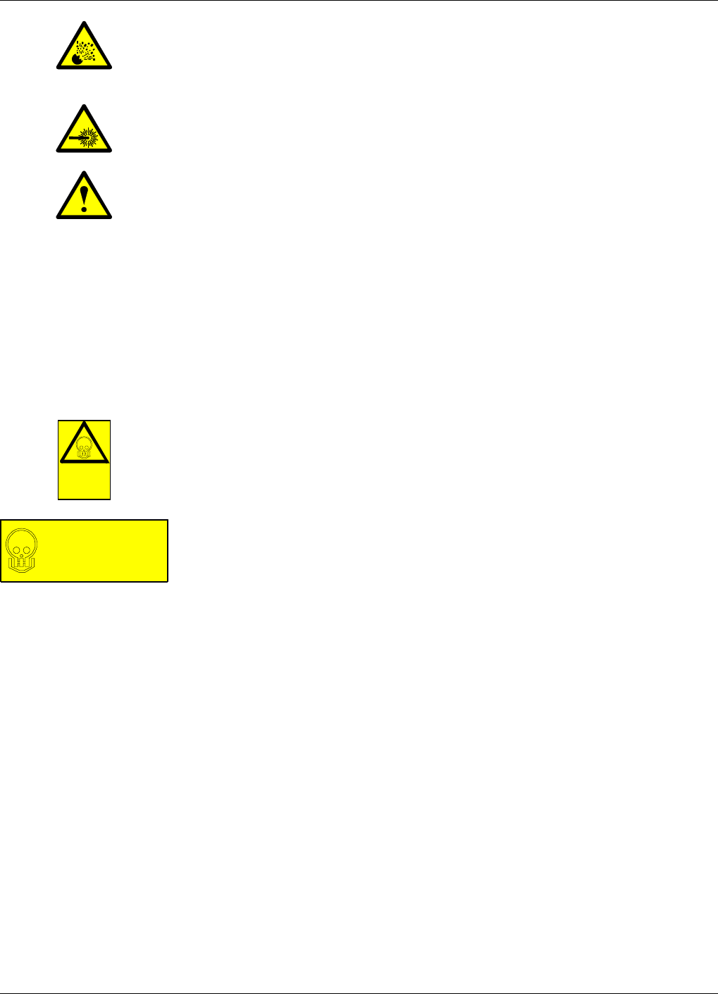
•A lithium battery is permanently mounted on the CU and FON boards.
Due to the risk of explosion, this battery must not be removed from the
board. In case of battery malfunction, replace the entire board. The
old board can be sent to Allgon for repair.
•The optional FON board contains a class 1 laser transmitter that emits
invisible laser radiation during operation. Avoid direct exposure from
unconnected laser transmitter or fiber cord.
•The heat sink element on a CDMA High Power repeater can be very
hot. Do not touch this surface during operation.
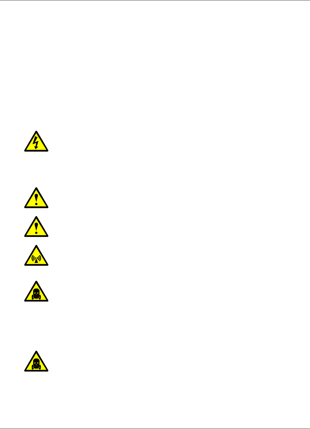
Warning Signs
The following warning signs must be observed and be kept clean and
readable.
Beryllium oxide
This warning sign is applied on boards and units which contain beryllium
oxide parts.
This warning sign is applied at the bottom, inside the cabinet, below the
power supply unit.
The previous section details parts containing beryllium oxide and how to
avoid dangerous dealing with these parts.
Beryllium
oxide
hazard
BERYLLIUM OXIDE
(Toxic)
used in equipment
see instruction book
Allgon Systems AB AR Repeaters Safety
VD204 43/EN - Installation Guide Rev. 1A 2001-06 1 - 2

Static Electricity
Static electricity means no risk of personal injury but it can severely
damage essential parts of the repeater, if not handled carefully.
Parts on the printed circuit boards as well as other parts in the repeater
are sensitive to electrostatic discharge.
Never touch the printed circuit boards or uninsulated conductor
surfaces unless absolutely necessary.
If you must handle the printed circuit boards or uninsulated conductor
surfaces, use ESD protective equipment, or first touch the repeater
chassis with your hand and then do not move your feet on the floor.
Never let your clothes touch printed circuit boards or uninsulated
conductor surfaces.
Always store printed circuit boards in ESD-safe bags.
Allgon Systems AB AR Repeaters Safety
VD204 43/EN - Installation Guide Rev. 1A 2001-06 1 - 3

2. Installation
Before installation, read carefully Chapter 1, Safety.
Siting the Repeater
Allgon repeaters are designed for outdoor usage. However, humidity and
temperature changes may have affect on the reliability. A preferable site
for the repeater is thus indoor, in a tempered and ventilated room.
Sunshine
If a repeater is placed outdoor and can be exposed to direct sunshine, it is
essential that the air can circulate around the repeater with no obstacle.
The operating temperature must not exceed +55°C. A shelter can be used
to shade the repeater from direct sunshine.
Shelter
Allgon repeaters are designed with a weather proof outdoor case that can
be mounted without any kind of shelter from rain, snow or hail.
If a repeater is to be opened on the site when raining, snowing, or hailing
there must be some kind of permanent or temporary shelter. This is
applicable to gentle rainfall, snowfall or hail. Limitations for very bad
weather is found in the next section.
Allgon can provide a shelter designed for these repeaters. This shelter is
shown in Figure 2-1.
Outdoor Installation and Service Limitations
Sited outdoors, the repeater must not be opened for installation or service
at bad weather, such as:
–Intense rainfall, snowfall or hail.
–Storm or high wind.
–Extremely low or high temperature.
–High humidity of the air.
Allgon Systems AB AR Repeaters Installation
VD204 43/EN - Installation Guide Rev. 1A 2001-06 2 - 1
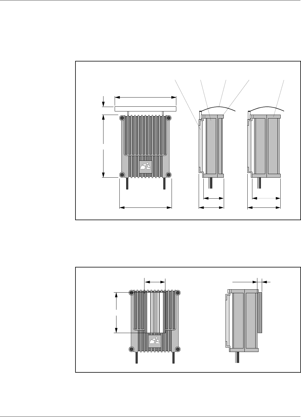
Dimensions and Weights
The dimensions of the repeater, including the mounting bracket, is shown
in Figure 2-1. The repeater chassis consists of two main parts, a cabinet
in which the circuitry is housed, and a cover, which can be either a low
cover or a high cover (see the figure) depending on the repeater type.
The high power CDMA and WCDMA repeaters have an external heat sink
on a high cover, see Figure 2-2.
440 (17.3")
530 (20.9")
520 (20.5"
)
110 (4.3")
ALLGON
174 (6.9")
224 (8.8")
240 (9.4")
290 (11.4")
Mounting bracket Cabinet Shelter Low cover High cover
Figure 2-1. Repeater dimensions
ALLGON
180 (7.1")
350 (13.8")
35 (1.4")
Figure 2-2. High power CDMA/WCDMA repeater
Allgon Systems AB AR Repeaters Installation
VD204 43/EN - Installation Guide Rev. 1A 2001-06 2 - 2

Approximately repeater weights
Repeater with a low cover ......................................................... 21 kg (46 lbs)
Repeater with an empty high cover .......................................... 25 kg (55 lbs)
Combined repeater with a high cover ...................................... 30 kg (66 lbs)
It is not recommended to remove the cover from the cabinet at the site.
However, if the cover, for some reason, has to be removed from the
cabinet, then disconnect the interconnection cables, close the cover,
remove the hinge shafts, and remove the cover.
The cabinet and cover weights are, approximately, as follows:
Empty low cover ........................................................................... 6 kg (13 lbs)
Empty high cover ....................................................................... 10 kg (22 lbs)
Equipped cabinet or high cover ................................................ 15 kg (33 lbs)
Allgon Systems AB AR Repeaters Installation
VD204 43/EN - Installation Guide Rev. 1A 2001-06 2 - 3
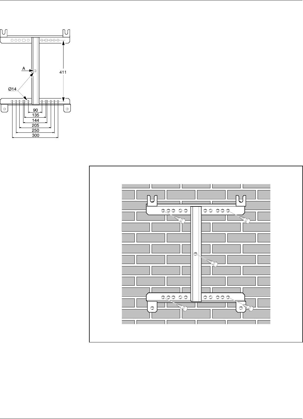
Mounting
The AR repeater is easy to mount using the provided mounting bracket,
which has Ø14mm (9/16") holes for 10mm (3/8") or 12mm (1/2") fixing
screws. Clamps with c-c measures of 90mm (3.5"), 135mm (5.3"), 144mm
(5.7"), 205mm (8.1"), 250mm (9.8"), and 300mm (11.8") can be used as
well. The vertical c-c measure for these are 411mm (16.2").
The mounting bracket is shown in the figure.
NOTE! There is a Ø14mm (9/16") single hole in the middle of the
mounting bracket, marked ’A’ in the figure, which is intended for a
locking screw, i.e. a screw which cannot be removed when the repeater is
put in the bracket.
Mount the repeater as follows:
1. Mount the provided bracket.
Normally, the repeater is mounted on a wall, pole, or mast. These
mounting cases are shown below.
Figure 2-3 shows a bracket attachment to a wall using four fixing
screws and a locking screw.
Figure 2-3. Attaching the bracket to a wall
Allgon Systems AB AR Repeaters Installation
VD204 43/EN - Installation Guide Rev. 1A 2001-06 2 - 4
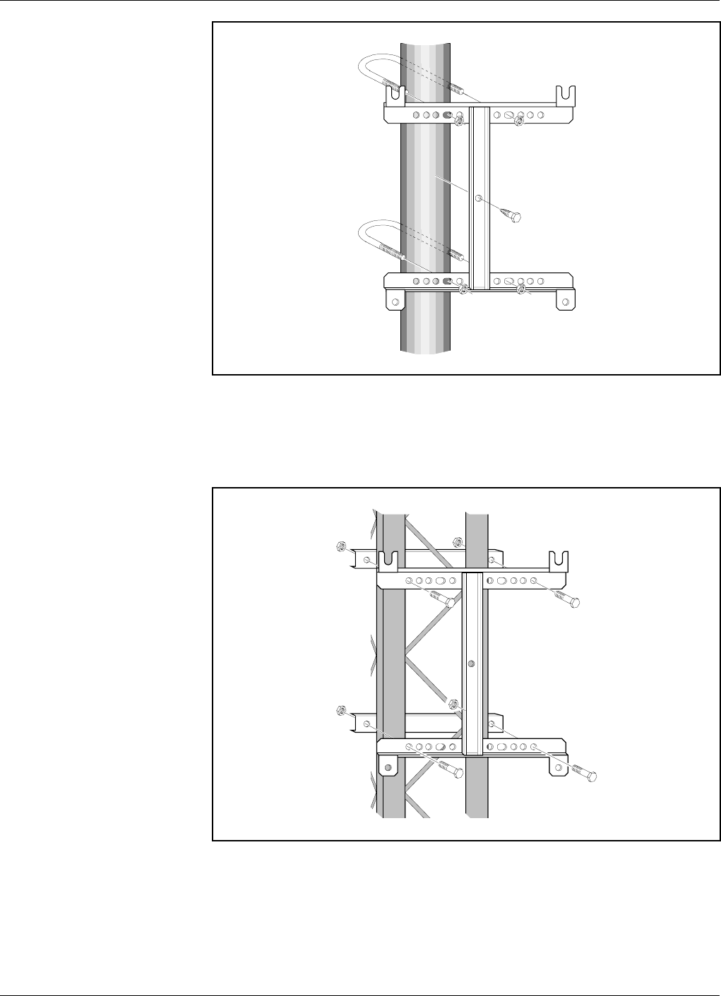
Figure 2-4 shows a bracket attachment to a pole using two 144mm
(5.7") U-shaped clamps and a locking screw.
Figure 2-5 shows a bracket attachment to a mast using two 300mm
(11.8") bar-shaped clamps and no locking screw.
Figure 2-4. Attaching the bracket to a pole
Figure 2-5. Attaching the bracket to a mast
Allgon Systems AB AR Repeaters Installation
VD204 43/EN - Installation Guide Rev. 1A 2001-06 2 - 5
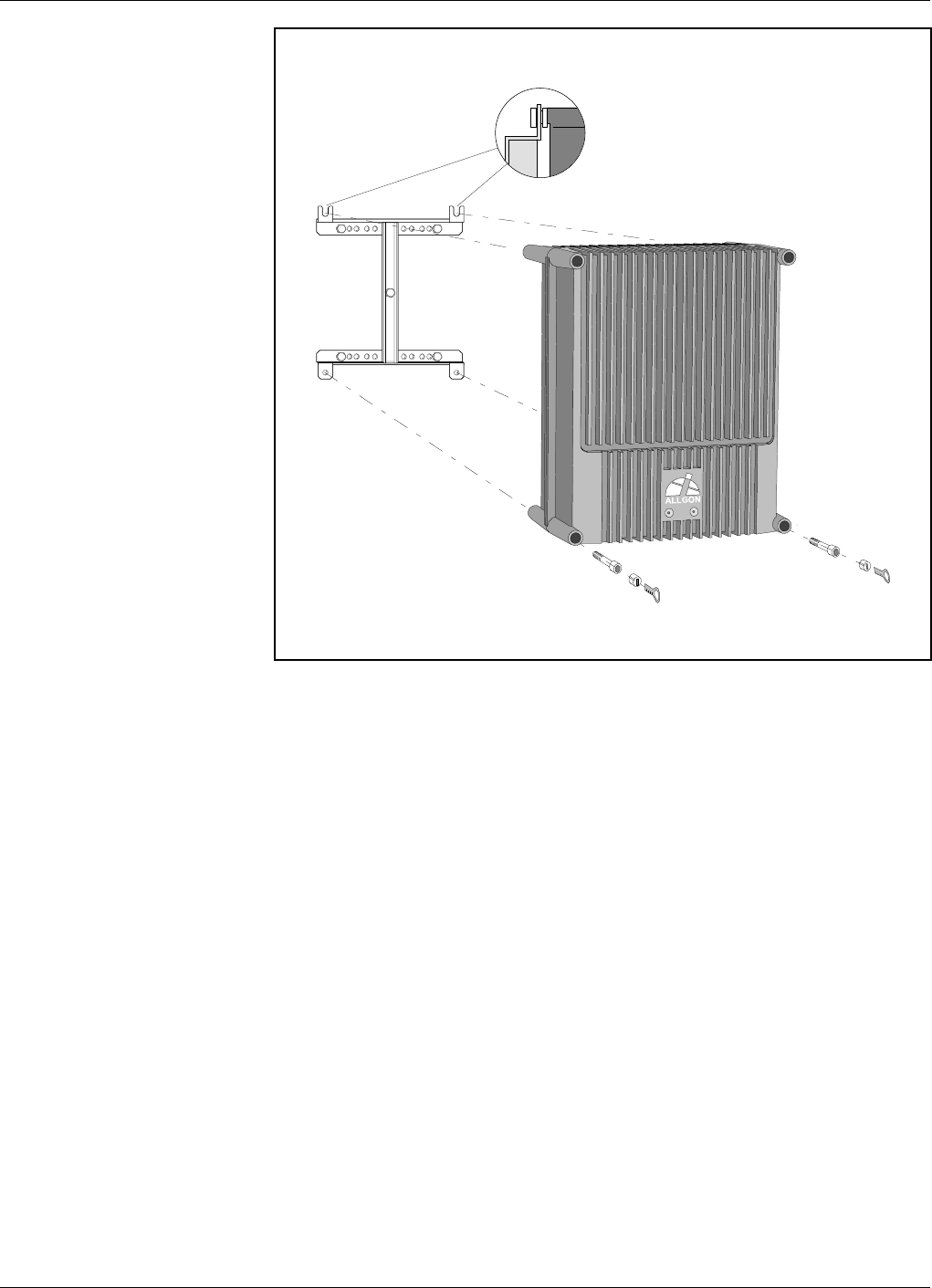
2. After attaching the bracket, hang the repeater on the upper supports
(see Figure 2-6) and use the screws for the lower ones. Tighten the
upper and lower screws.
There are locking cylinders that can be inserted and locked with a
key after the lower screws have been tightened (see Figure 2-6).
These prevents from unauthorized removal of the repeater.
3. Make sure the donor antenna, directed towards the base station
antenna, is mounted.
4. Make sure the service antenna, directed towards the area to be
covered by the repeater, is mounted.
Figure 2-6. Attaching the repeater to the bracket
Allgon Systems AB AR Repeaters Installation
VD204 43/EN - Installation Guide Rev. 1A 2001-06 2 - 6

Connection
This section describes how to connect the input and output ports of the
repeater types:
AR repeaters (except for high power CDMA/WCDMA) ................ page 2-8
High power CDMA/WCDMA .................................................................... 2-9
BMU ............................................................................................................. 2-10
RMU ............................................................................................................. 2-11
FOR .............................................................................................................. 2-12
Common important instructions for the repeater types are found below.
Station ground
There is a screw to the left in the repeater that is intended for station
ground only. This screw is marked with the ground symbol.
Mains connection
Note that local regulations are to be followed for the mains connection.
The AR repeater is approved in accordance with EN and UL/cUL
regulations. This is, however, only valid if a classified power cord is used.
To get the repeater to meet these regulations, select one of the following
classified and approved cord types:
•EN- H 05 W5 - F HMR.
•UL- AWM Style 2587.
•CSA - AWM 1 A/B 11 A/B.
For outdoor use the power cord should meet at least IP65 encapsulation
requirements.
For repeaters supplied from the mains, the mains outlet must be grounded.
The mains connection described on the following pages means to mount
the mains plug to the mains cord (if to be used) but it does not mean to
connect the mains.
Do not turn the mains on until you are commissioning the repeater (see
Chapter 4, Commissioning, in the AR Repeaters, User’s Manual).
RCU and RCC remote control units
All AR repeaters can be equipped with an RCU, Remote Control Unit.
The GSM antenna for this unit is internally connected in the repeater.
If the RCU is removed, then the jumper between pin 2 and 3 on the P27
port must be reconnected. Do not connect the jumper to another position
than between pin 2 and 3 on the P27 port.
An RCC, Remote Communication Control unit, is required if the unit is to
be connected to a FON board (the FON board does not support the RCU).
A description of the RCC and its connection is found in the VD203 67/EN,
ALR Compact Repeater, User’s Manual. The RCU and RCC are described
in Chapter 6, Optionals, in the AR Repeaters, User’s Manual.
Allgon Systems AB AR Repeaters Installation
VD204 43/EN - Installation Guide Rev. 1A 2001-06 2 - 7
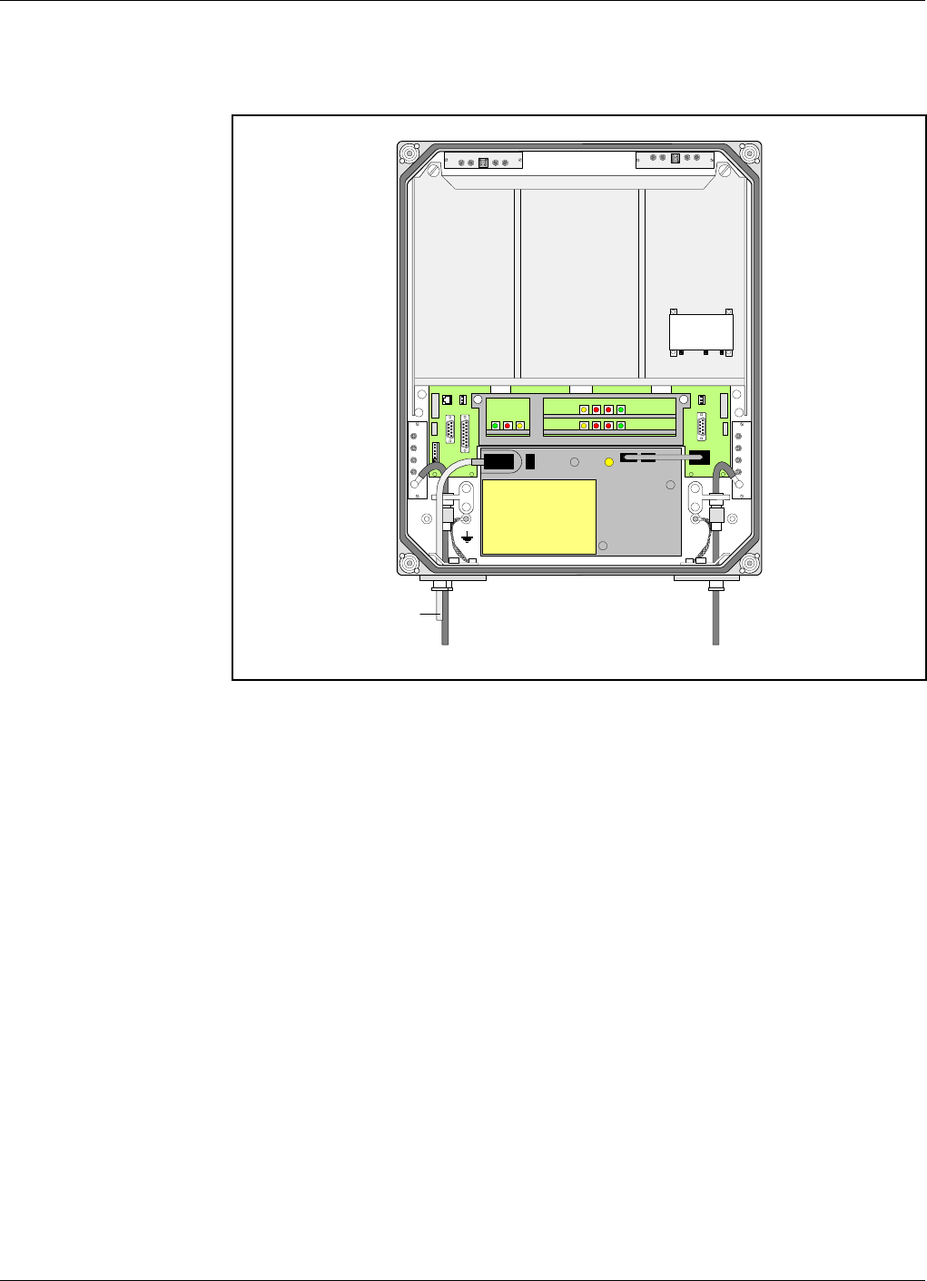
Connecting AR Repeater
This description is not applicable to a high power CDMA or WCDMA
repeater.
1. Connect the service and donor antenna coaxial cables (or RF cable
from the BTS if no donor antenna is used). Use N type male
connectors.
–The donor antenna or RF cable from the BTS is connected to the
right in the cabinet (’BS’ in Figure 2-7).
–The service antenna (MS) is connected to the left in the cabinet.
2. Connect station ground, if to be used (see page 2-7).
3. Mount the mains plug to the mains cord (if to be used) but do not
connect the mains (see page 2-7).
4. Connect external alarm and optional door open alarm, if this feature
is to be used. Descriptions are found on page 2-13.
5. Connect the R2R cables, if this feature is to be used (see page 2-14).
6. Connect a mains breakdown relay, if mains breakdown alarm is to be
used (see page 2-15).
MS
DPX
ANT
TEST
DC
-30 dB
-20 dB MS
DPX
ANT
TEST
DC
-30 dB
-20 dB
MS BS
OUT
LOW
IN+7V ATTOUT2 OUT1
LNA
DL
OUT
LOW IN ATT +7V OUT1 OUT2
LNA
UL
PSU
Mains
Figure 2-7. Connecting AR repeater
Allgon Systems AB AR Repeaters Installation
VD204 43/EN - Installation Guide Rev. 1A 2001-06 2 - 8
Connecting High Power CDMA or WCDMA Repeater
This description is applicable to a high power CDMA or WCDMA repeater.
1. Connect the service and donor antenna coaxial cables (or RF cable
from the BTS if no donor antenna is used). Use N type male
connectors.
–The donor antenna or RF cable from the BTS is connected to the left
in the cabinet (’BS’ in Figure 2-7).
–The service antenna (MS) is connected to the right in cabinet.
2. Connect station ground, if to be used (see page 2-7).
3. Mount the mains plug to the mains cord (if to be used) but do not
connect the mains (see page 2-7).
4. Connect external alarm and optional door open alarm, if this feature
is to be used. Descriptions are found on page 2-13.
5. Connect the R2R cables, if this feature is to be used (see page 2-14).
6. Connect a mains breakdown relay, if mains breakdown alarm is to be
used (see page 2-15).
MS
DPX
ANT
TEST
DC
-30 dB
-20 dB
MRX
MS
DPX
ANT
TEST
DC
-30 dB
-20 dB
BS MS
OUT
LOWIN+7V ATTOUT2 OUT1
LNA
DL
OUT
LOW IN ATT +7V OUT1 OUT2
LNA
UL
PSU
Mains
Figure 2-8. Connecting high power CDMA/WCDMA repeater
Allgon Systems AB AR Repeaters Installation
VD204 43/EN - Installation Guide Rev. 1A 2001-06 2 - 9
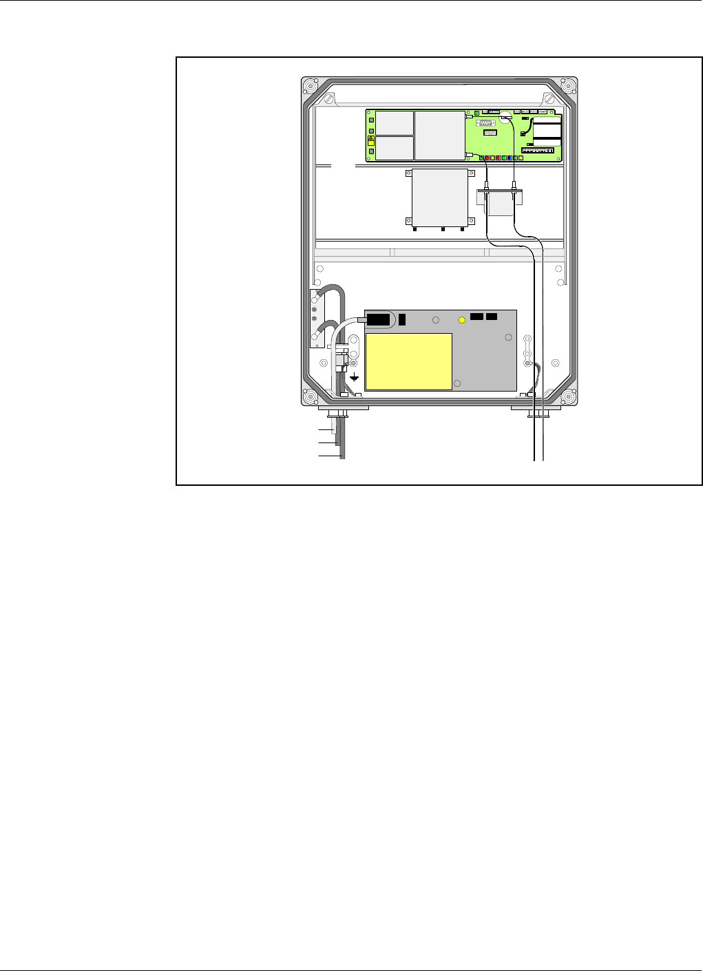
Connecting BMU
Figure 2-9 shows an BMU with separate RX/TX fiber optic cables to one
FOR. By using WDMs and OSPs, up to four FORs can be fed in parallel
by a BMU with double or single fiber communication. Up to eight FORs
can be fed with a high cover and two FOUs.
1. Connect the BTS antenna output RF cable to the ANT port of the
DC unit to the left in the cabinet. Use an N type male connector.
2. Connect an RF cable from the DPX port of the DC unit to the left in
the repeater to the BTS antenna. Use an N type male connector.
3. Connect the RX and TX fiber optic cables from the FON board
located in the upper part of the FOU to an FOR.
4. Connect station ground, if to be used (see page 2-7).
5. Mount the mains plug to the mains cord (if to be used) but do not
connect the mains (see page 2-7).
6. Connect external alarm, if this feature is to be used. Descriptions are
found on page 2-13.
7. Connect the R2R cables, if this feature is to be used (see page 2-14).
8. Connect a mains breakdown relay, if mains breakdown alarm is to be
used (see page 2-15).
P102
P130
Beryllium
oxide
hazard
P103
P101
P114
P108P112P111
P105
P110
P109P115
P106
P104
RX
TX
P113
FOU
FON
MS
DPX
ANT
TEST
DC
-30 dB
-20 dB
BTS TX RX
FOR
PSU
Mains
BTS antenna output
BTS antenna
Figure 2-9. Connecting BMU
Allgon Systems AB AR Repeaters Installation
VD204 43/EN - Installation Guide Rev. 1A 2001-06 2 - 10
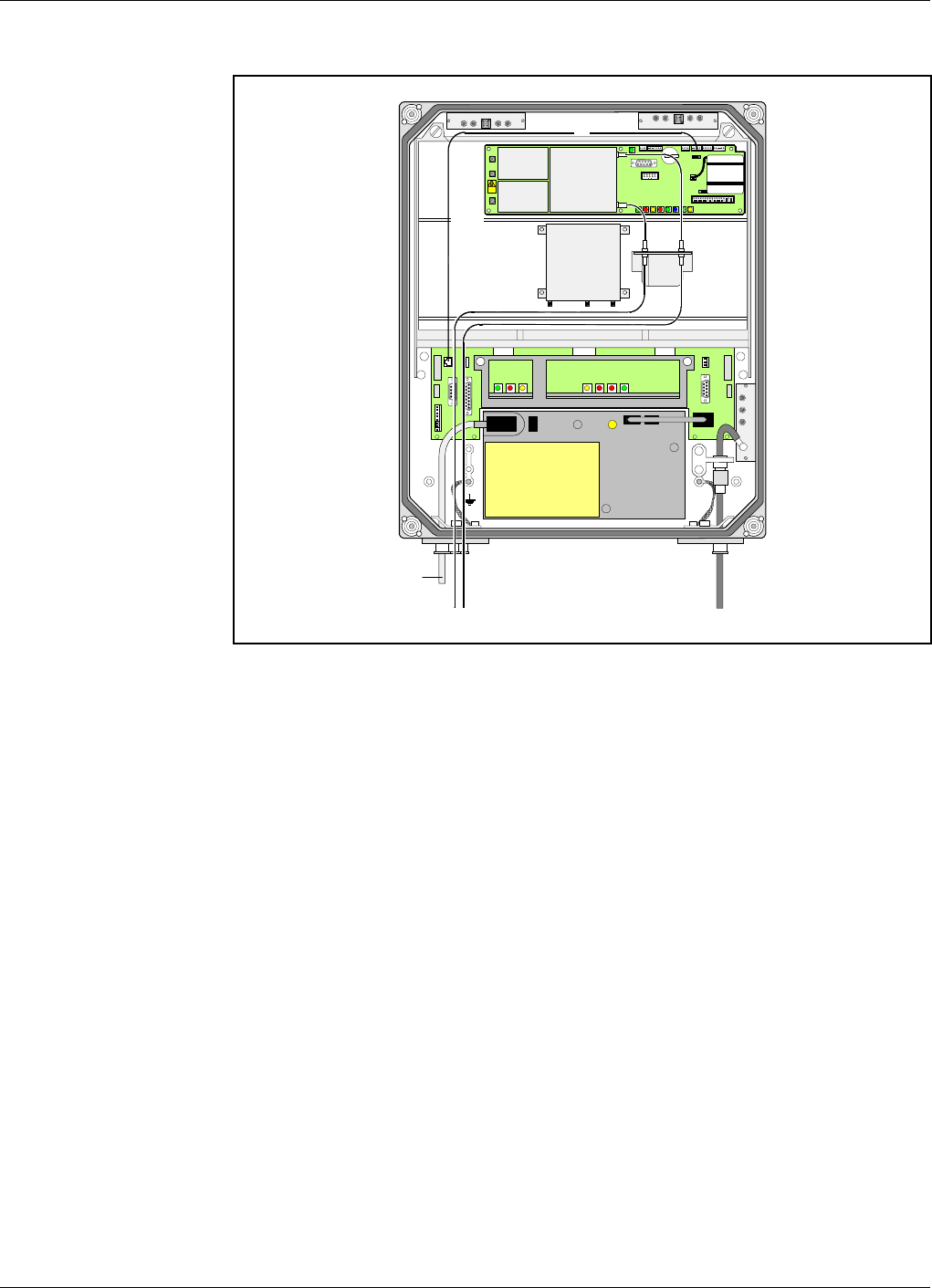
Connecting RMU
Figure 2-10 shows an RMU for donor antenna and separate RX/TX fiber
optic cables to one FOR. By using WDMs and OSPs, up to four FORs can
be fed in parallel by an RMU with double or single fiber communication.
Up to eight FORs can be fed with a high cover and two FOUs.
1. Connect the donor antenna coaxial cable to the right in the cabinet
(’BS’ in Figure 2-10). Use an N type male connector.
2. Connect the RX and TX fiber optic cables from the FON board
located in the upper part of the FOU to an FOR.
3. Connect station ground, if to be used (see page 2-7).
4. Mount the mains plug to the mains cord (if to be used) but do not
connect the mains (see page 2-7).
5. Connect external alarm and optional door open alarm, if this feature
is to be used. Descriptions are found on page 2-13.
6. Connect the R2R cables, if this feature is to be used (see page 2-14).
7. Connect a mains breakdown relay, if mains breakdown alarm is
available and is to be used (see page 2-15).
MS
DPX
ANT
TEST
DC
-30 dB
-20 dB
TX
BS
P102
P130
Beryllium
oxide
hazard
P103
P101
P114
P108P112P111
P105
P110
P109P115
P106
P104
RX
TX
P113
RX
OUT
LOW IN ATT +7V OUT1 OUT2
LNA
UL OUT
LOW
IN+7V ATTOUT2 OUT1
LNA
DL
FOU
FON
FOR
PSU
R2R
Mains
Figure 2-10. Connecting RMU
Allgon Systems AB AR Repeaters Installation
VD204 43/EN - Installation Guide Rev. 1A 2001-06 2 - 11
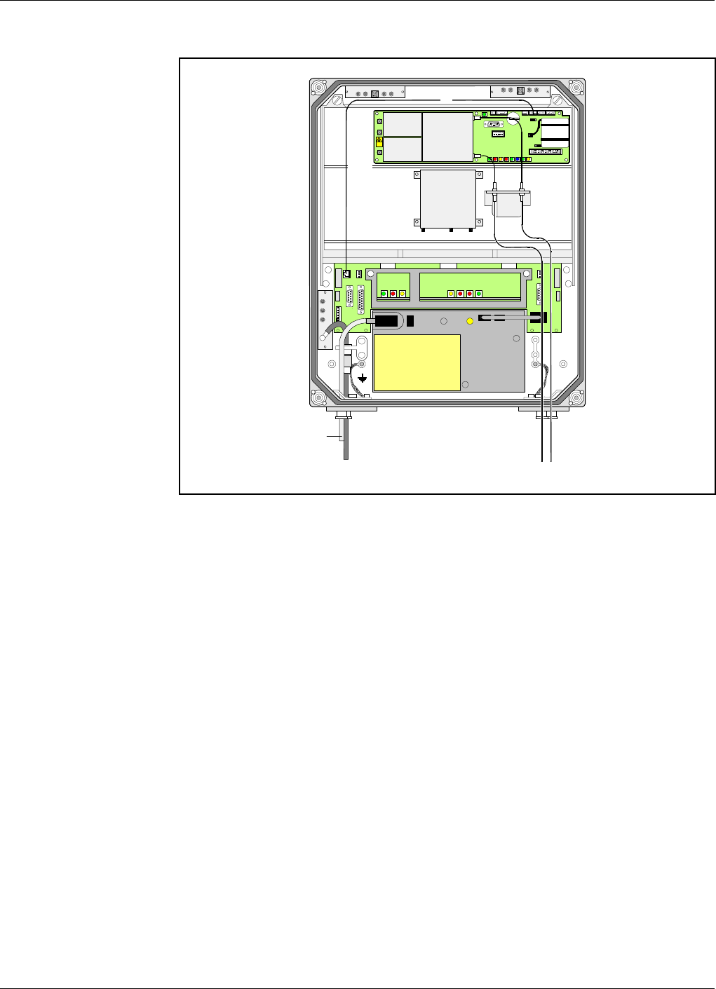
Connecting FOR
Figure 2-11 shows a FOR for service antenna and separate RX/TX fiber
optic cables from a BMU. By adding WDMs and OSPs, a number of FORs
can be fed by one BMU with double or single fiber communication.
1. Connect the service antenna coaxial cable to the left in the cabinet
(’MS’ in Figure 2-10). Use an N type male connector.
2. Connect the RX and TX fiber optic cables from the BMU to the FON
board located in the upper part of the FOU.
3. Connect station ground, if to be used (see page 2-7).
4. Mount the mains plug to the mains cord (if to be used) but do not
connect the mains (see page 2-7).
5. Connect external alarm and optional door open alarm, if this feature
is to be used. Descriptions are found on page 2-13.
6. Connect the R2R cables, if this feature is to be used (see page 2-14).
7. Connect a mains breakdown relay, if mains breakdown alarm is to be
used (see page 2-15).
MS
DPX
ANT
TEST
DC
-30 dB
-20 dB
MS TX
P102
P130
Beryllium
oxide
hazard
P103
P101
P114
P108P112P111
P105
P110
P109P115
P106
P104
RX
TX
P113
OUT
LOW
IN+7V ATTOUT2 OUT1
LNA
DL
OUT
LOW IN ATT +7V OUT1 OUT2
LNA
UL
RX
FOU
FON
BMU
PSU
R2R
Mains
Figure 2-11. Connecting FOR
Allgon Systems AB AR Repeaters Installation
VD204 43/EN - Installation Guide Rev. 1A 2001-06 2 - 12
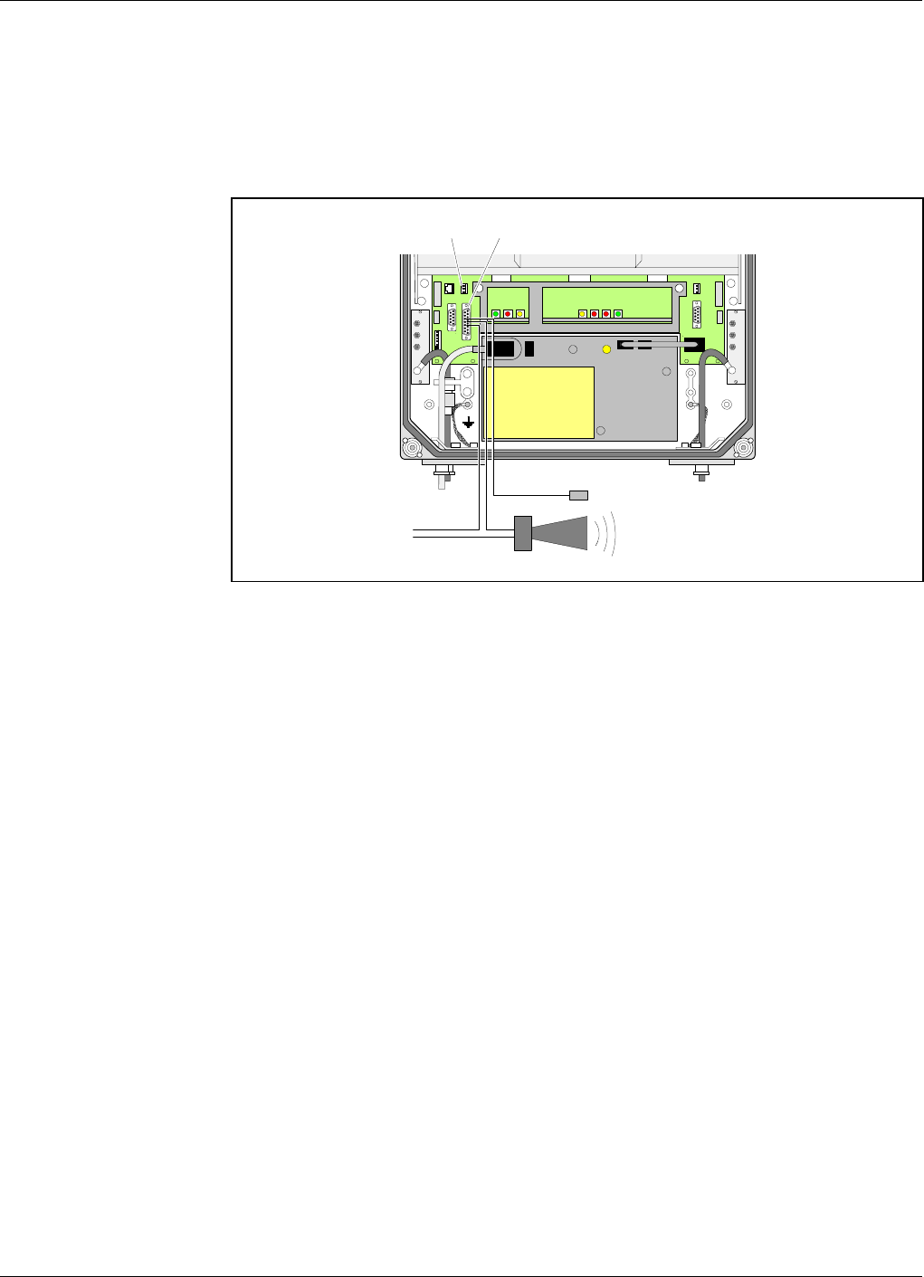
External Alarm
Burglary, fire or other external alarm can be used in the repeaters.
Optical or acoustic alarm can also be connected to the repeaters.
External alarm sensors and alarm signals are connected to the P33 alarm
port located to the left in the cabinet (see Figure 2-12).
The P33 alarm port is described in the Connection Ports section on
page 2-18.
Use a 15 pole D-sub male connector for this connection.
The cable for this installation is taken through a strain relief bushing at
the bottom of the repeater.
For a repeater without a CU board, i.e. BMU, external alarm is connected
to the P109 port on the FON board. The P109 port is described in the
FON - Fiber Optic Node Board section in the AR Repeaters, User’s
Manual, Chapter 5.
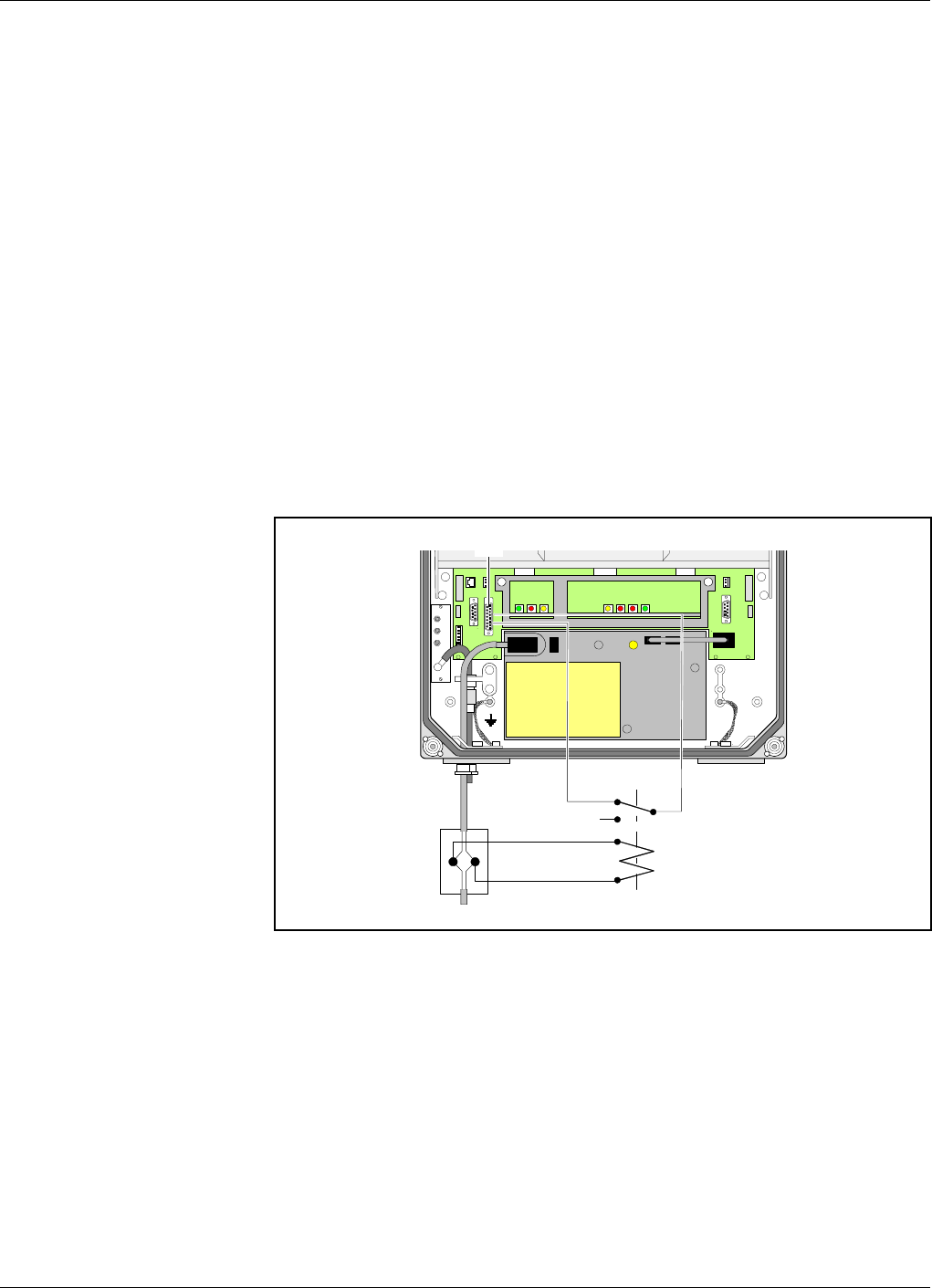
Door Open Alarm
A door open alarm can be used in all repeater types that have a CU
board, i.e. all types except for BMU. This is arranged with a door switch
connected to the P28 port (see Figure 2-12). The P28 port and the
connection is described in the Connection Ports section on page 2-18.
MS
DPX
ANT
TEST
DC
-30 dB
-20 dB
P28 P33
MS
DPX
ANT
TEST
DC
-30 dB
-20 dB
External alarm sensors
External alarm
Figure 2-12. External alarm connection
Allgon Systems AB AR Repeaters Installation
VD204 43/EN - Installation Guide Rev. 1A 2001-06 2 - 13
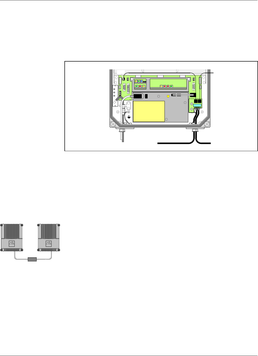
R2R, Repeater to Repeater Link
Connect the R2R cable, if this optional feature is to be used. See also the
F2F, Fiber to Fiber Link section below.
The R2R net cable is connected to the P34 Repeater to Repeater Link
port via the P1 terminal on the R2R connector board to the right in the
repeater (see Figure 2-13).
The P34, Repeater to Repeater Link port, is described in the Connection
Ports section on page 2-18.
Any cable type can be used for indoor installation.
The following cable type is recommended for outdoor installation:
Li 2YC11Y, 2x2xAWG24/222, non-halogen, Metrofunkkabel-Union.
Use a strain relief bushing or a connector at the bottom of the repeater
for the external net cable.
If the link cable between two repeaters in an R2R net is longer than
25 meters, then an RS-485 repeater is required, see the figure.
Further information about the Repeater to Repeater Link is found in the
VD202 91/EN, R2R, Repeater to Repeater Link Kit, Installation Guide.
F2F, Fiber to Fiber Link
F2F is a feature that makes it possible to communicate with all repeaters
that have a FON board (i.e. BMU, RMU and FOR) and are included in
the same fiber optic net. By using the existing fiber optic distribution net,
no wire or other communication device is required.
Communication with repeaters works also in mixed F2F and R2R net.
MS
DPX
ANT
TEST
DC
-30 dB
-20 dB
P31
P3 P2
P1
Figure 2-13. R2R connection
>25m
ALLGONALLGON
Allgon Systems AB AR Repeaters Installation
VD204 43/EN - Installation Guide Rev. 1A 2001-06 2 - 14
Mains Breakdown Relay
To be able to distinguish PSU faults from power failure, a mains
breakdown relay can be used.
The mains breakdown relay is not included in the repeater. So, it has to
be mounted outside the repeater chassis. The relay intended for this
purpose must fulfil the following specifications:
Relay specification
Closing time: Max. 30 milliseconds.
Insulation coil/contact: Min. 4KV.
Mains connected relay must be in compliance with valid local regulations.
Connection
1. Connect a currentless closed relay contact to pin AI1 and AIC on the
P33 alarm connector see Figure 2-14. Alarm is initiated by short
circuiting pin AI1 and AIC in the P33 connector.
The P33 alarm port is described in the Connection Ports section on
page 2-18.
2. Connect the relay coil. It must be supplied from the same fuse as the
repeater.
3. After commissioning, select the Mains Breakdown option in the alarm
configuration dialog box in the OMT32 or OMS program. Refer to
the OMT32, User’s Manual or the Advanced Repeater OMS, User’s
Manual.
MS
DPX
ANT
TEST
DC
-30 dB
-20 dB
P33:AICP33:AI1
P33
Figure 2-14. Mains breakdown relay connection
Allgon Systems AB AR Repeaters Installation
VD204 43/EN - Installation Guide Rev. 1A 2001-06 2 - 15

Finishing the Installation
Check all connections made.
If a 24 Volt or 48 Volt power supply unit is to be used, then replace the
PSU as described in the next section.
When ready with the installation, commission the repeater as described in
Chapter 4, Commissioning, in the AR Repeaters, User’s Manual.
Allgon Systems AB AR Repeaters Installation
VD204 43/EN - Installation Guide Rev. 1A 2001-06 2 - 16
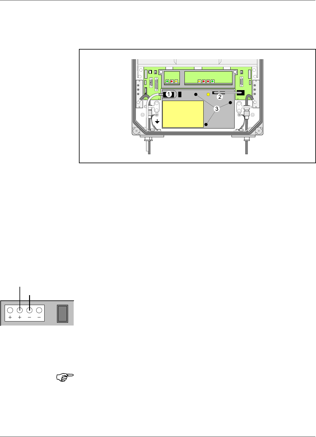
Installing 24 Volt or 48 Volt DC Power Supply Unit
The 220V AC PSU can be replaced with a 24 Volt or 48 Volt DC PSU as
described below.
1. Switch the repeater off and remove the mains plug from the PSU
(’1’ in Figure 2-15).
2. Disconnect the two connectors (2) on the PSU.
3. Loosen the three fixing screws (3) using a 5mm Allen key.
4. Remove the PSU from the repeater.
5. Mount the 24/48 Volt DC PSU with the three fixing screws (3).
6. Connect the PSU to the DIA board (2).
7. Connect the DC power cable. The supplied cable should have a
radiation limiter. The cable shall be connected as follows:
The + pole shall be connected to one of the left terminals in the PSU
connector with the brown part of the DC cable.
The – pole shall be connected to one of the right terminals in the
PSU connector with the blue part of the DC cable.
8. Switch the repeater on.
9. The yellow LED on the PSU shall now be lit.
The DC Power Supply Unit must be galvanically separated from the mains
supply with an equipment fulfilling the IEC65 safety requirements.
MS
DPX
ANT
TEST
DC
-30 dB
-20 dB
MS
DPX
ANT
TEST
DC
-30 dB
-20 dB
PSU
Figure 2-15. Replacing mains PSU with 24V or 48V
Blue
Brown
Allgon Systems AB AR Repeaters Installation
VD204 43/EN - Installation Guide Rev. 1A 2001-06 2 - 17
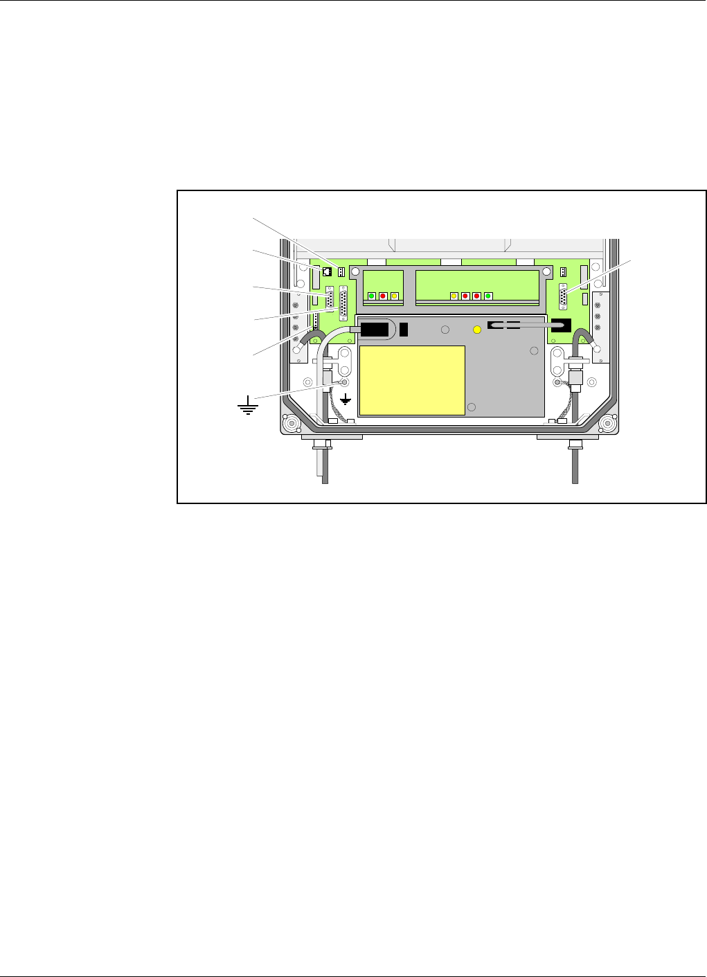
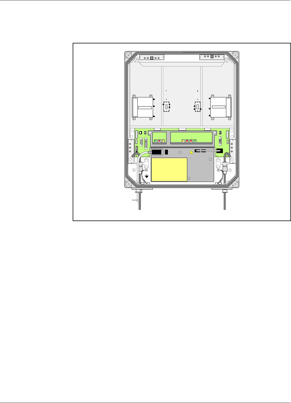
Connection Ports
The DIA distribution board provides most of the internal connection
between the repeater units, and to external ports. Connectors involved in
the installation are also located on the DIA board. These connectors are
described below. A complete DIA board connector list is found in
Chapter 5 of the AR Repeaters, User’s Manual.
Figure 2-16 shows the location of the connection ports.
Station ground is also shown in Figure 2-16 (at the ground symbol).
The port descriptions are found on the following pages:
P27 Auxiliary Port ............................................................................ page 2-19
P28 Door switch alarm input port ............................................................ 2-21
P31 PC Port ................................................................................................ 2-19
P32 Modem Port ........................................................................................ 2-20
P33 Alarm Port .......................................................................................... 2-20
P34 Repeater to Repeater Link Port ........................................................ 2-22
MRX
DPX
ANT
TEST
DC
-30 dB
BS
-20 dB
MRX
DPX
ANT
TEST
DC
-30 dB
P33
P27
P31
P32
P28
P34
Figure 2-16. Connection ports and station ground
Allgon Systems AB AR Repeaters Installation
VD204 43/EN - Installation Guide Rev. 1A 2001-06 2 - 18
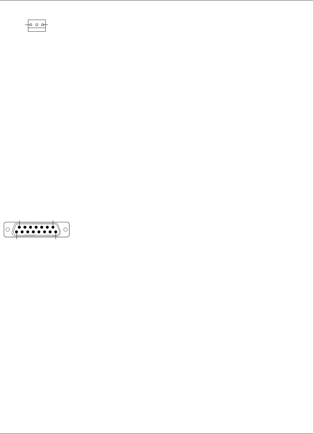
P27 Auxiliary Port
Auxiliary port P27 is used to power the RCU, Remote Control Unit, for
communication with the repeater.
The connector is found on the DIA board to the left in the cabinet.
P27 is an 8 pole, 1 line male connector.
Pin 2 and 3 of the P27 port must always be interconnected to provide the
CU and ALI boards with voltage supply. If there is no cable connected to
the P27 port, pin 2 and 3 must be interconnected with a jumper.
P27 auxiliary connector pinning
Pin 1 +7V DC.
Pin 2 +7V DC.
Pin 3 CU and ALI power supply from pin 2.
Pin 4 GND
Pin 5 +26V DC or +13V DC depending on the repeater type.
Pin 6 Not used.
Pin 7 Output 200KHz reference.
Pin 8 GND
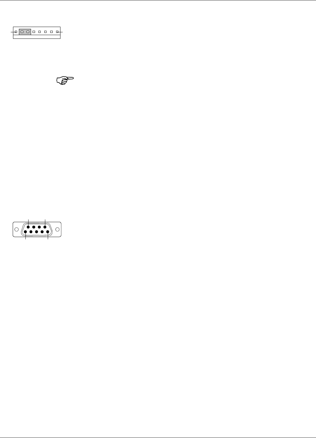
P31 PC Port
PC port P31 is a RS-232 port used for local PC communication.
The connector is found on the DIA board to the right in the cabinet.
P31 is a 9 pole D-sub female connector.
P31 PC connector pinning
Pin 1 Not used.
Pin 2 Data from repeater to OMT32.
Pin 3 Data from OMT32 to repeater.
Pin 4 DTR from OMT32 to repeater.
Pin 5 GND
Pin 6 DSR from repeater to OMT32.
Pin 7 RTS from OMT32 to repeater.
Pin 8 CTS from repeater to OMT32.
Pin 9 Not used.
18
51
6 9
Allgon Systems AB AR Repeaters Installation
VD204 43/EN - Installation Guide Rev. 1A 2001-06 2 - 19
P32 Modem Port
Modem port P32 is a RS-232 port with V.24 interface used for the RCU,
Remote Control Unit.
The connector is found on the DIA board to the left in the cabinet.
P32 is a 9 pole D-sub male connector.
P32 modem connector pinning
Pin 1 DCD
Pin 2 RXD
Pin 3 TXD
Pin 4 DTR
Pin 5 GND
Pin 6 DSR
Pin 7 RTS
Pin 8 RFS
Pin 9 RI
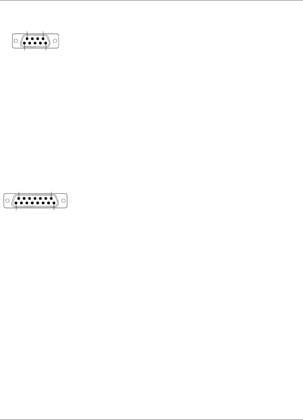
P33 Alarm Port
Alarm port P33 is used for external alarm sensors and alarm equipment.
The connector is found on the DIA board to the left in the cabinet.
P33 is a 15 pole D-sub female connector.
The port has four alarm inputs, EAL1 - EAL4, and two alarm outputs.
Four alarm inputs
The inputs are low-level inputs with common ground (AIC).
Use insulated switch or relay to initiate alarms (open switches in normal
operating mode, closed switches cause alarm).
The alarm switch connection can be toggled between being active open or
active closed. This is further described in the OMT32, User’s Manual and
in the Advanced Repeater OMS, User’s Manual.
The alarm input voltage ratings, related to ground (AIC), are:
Vinmax = 5.5V
Vinmin =–0.5V
P33 alarm connector pinning
Pin 14 AI1 External alarm input 1 - EAL1.
Pin 15 AI2 External alarm input 2 - EAL2.
Pin 7 AI3 External alarm input 3 - EAL3.
Pin 8 AI4 External alarm input 4 - EAL4.
Pin 6 AIC Ground.
5 1
69
81
159
Allgon Systems AB AR Repeaters Installation
VD204 43/EN - Installation Guide Rev. 1A 2001-06 2 - 20
P28 - AI4 door switch alarm input
Normally, alarm input AI4 is used for repeater cover opening alarm
EAL4, which is arranged using a door switch (optional). Because of that,
AI4 and AIC are available also in the P28 connector, to which the door
switch is connected.
The connector is found on the DIA board to the left in the cabinet.
The EAL4 door switch alarm is activated 10 – 30 seconds after the cover
has been opened.
Two alarm outputs
Both the alarm outputs are 1 pole closing and 1 pole opening relay
outputs insulated from each other.
Maximum ratings, related to ground or any other alarm terminal, are
50VAC/60VDC.
The alarm outputs are defined as follows:
Pin 9-1 AO1 – AO8 Closed when operating, otherwise open.
Pin 10-2 AO6 – AO7 Open when operating, otherwise closed.
Pin 11-3 AO2 – AO5 Closed at alarm state, otherwise open.
Pin 12-4 AO3 – AO4 Open at alarm state, otherwise closed.
P33 alarm connector pinning
Pin 1 AO8
Pin 2 AO7
Pin 3 AO5
Pin 4 AO4
Pin 5 Not used.
Pin 6 AIC
Pin 7 AI3
Pin 8 AI4
Pin 9 AO1
Pin 10 AO6
Pin 11 AO2
Pin 12 AO3
Pin 13 Not used.
Pin 14 AI1
Pin 15 AI2
13
81
159
Allgon Systems AB AR Repeaters Installation
VD204 43/EN - Installation Guide Rev. 1A 2001-06 2 - 21

P34 Repeater to Repeater Link Port
The P34 port is used for the R2R, Repeater to Repeater Link, which is an
optional feature for the AR repeaters. This port is also used to
interconnect the F2F, Fiber to Fiber Link feature, to the R2R net.
The connector is found on the DIA board to the left in the cabinet.
P34 is an 8 pole RJ45 modular female connector.
By interconnecting the P111 or P112 on the FON board to this port, the
F2F net is included in the R2R net and all repeaters in both the nets are
accessible.
P34 Repeater to Repeater Link connector pinning
Pin 1 C/S
Pin 2 GND
Pin 3 D–
Pin 4 D+
Pin 5 D+
Pin 6 D–
Pin 7 GND
Pin 8 C/S
For further information about the Repeater to Repeater Link installation,
refer to the VD202 91/EN R2R, Repeater to Repeater Link Kit, Installation
Guide.
Allgon Systems AB AR Repeaters Installation
VD204 43/EN - Installation Guide Rev. 1A 2001-06 2 - 22

Index
C
Connection .................................................................................................................. 2-7
AR repeaters (except for high power CDMA) .................................................... 2-8
BMU ..................................................................................................................... 2-10
donor antenna ..................................................................................... 2-8 - 2-9, 2-11
external alarm ..................................................................................................... 2-13
FOR ...................................................................................................................... 2-12
High power CDMA or WCDMA repeater ........................................................... 2-9
mains .......................................................................................................... 2-8 - 2-12
Repeater to Repeater Link ................................................................................ 2-14
RMU ..................................................................................................................... 2-11
service antenna ................................................................................... 2-8 - 2-9, 2-12
Connection ports ...................................................................................................... 2-18
D
DIA, Distribution board .......................................................................................... 2-18
Dimensions ................................................................................................................. 2-2
Donor antenna ................................................................................. 2-6, 2-8 - 2-9, 2-11
Door open alarm ...................................................................................................... 2-13
Door switch ...................................................................................................... 2-13, 2-21
E
EAL1 ......................................................................................................................... 2-20
EAL2 ......................................................................................................................... 2-20
EAL3 ......................................................................................................................... 2-20
EAL4 .............................................................................................................. 2-20 - 2-21
ESD ............................................................................................................................. 1-3
External alarm ......................................................................................................... 2-13
External alarm input ............................................................................................... 2-20
F
F2F, Fiber to Fiber Link ................................................................................ 2-14, 2-22
H
Hail .............................................................................................................................. 2-1
M
Mains breakdown relay ........................................................................................... 2-15
Mains connection ....................................................................................................... 2-7
Mounting ........................................................................................................... 2-4 - 2-6
Mounting bracket ............................................................................................. 2-4 - 2-6
O
Outdoor installation .................................................................................................. 2-1
Allgon Systems AB AR Repeaters Index
VD204 43/EN - Installation Guide Rev. 1A 2001-06 I - 1

P
Ports
AI ..................................................................................................... 2-15, 2-20 - 2-21
AO ........................................................................................................................ 2-21
P111 ..................................................................................................................... 2-22
P112 ..................................................................................................................... 2-22
P27 Auxiliary ...................................................................................................... 2-19
P28 Door switch ........................................................................................ 2-13, 2-21
P31 PC ................................................................................................................. 2-19
P32 Modem ......................................................................................................... 2-20
P33 Alarm ............................................................................. 2-13, 2-15, 2-20 - 2-21
P34 Repeater to Repeater Link ......................................................................... 2-22
P34 Repeater to Repeater Link port ................................................................ 2-14
Power cord .................................................................................................................. 2-7
Power Supply Unit, 24 or 48 Volt DC ................................................................... 2-17
R
R2R, Repeater to Repeater Link ................................................................... 2-14, 2-22
Rain ............................................................................................................................. 2-1
RCC, Remote Communication Control unit ............................................................ 2-7
RCU, Remote Control Unit ....................................................................................... 2-7
Repeater to Repeater Link
See R2R, Repeater to Repeater Link
S
Safety .......................................................................................................................... 1-1
beryllium oxide ..................................................................................................... 1-1
electric shock ......................................................................................................... 1-1
hydrogen fluoride .................................................................................................. 1-1
laser transmitter ................................................................................................... 1-2
lithium battery ...................................................................................................... 1-2
polytetrafluoro ethylene ....................................................................................... 1-1
PTFE ..................................................................................................................... 1-1
Service antenna ................................................................................ 2-6, 2-8 - 2-9, 2-12
Service limitations ..................................................................................................... 2-1
Shelter ......................................................................................................................... 2-1
Siting the repeater ..................................................................................................... 2-1
Snow ............................................................................................................................ 2-1
Static electricity ......................................................................................................... 1-3
Station ground ........................................................................................................... 2-7
Sunshine ..................................................................................................................... 2-1
W
Warning signs
beryllium oxide ..................................................................................................... 1-2
Weights ....................................................................................................................... 2-2
Allgon Systems AB AR Repeaters Index
VD204 43/EN - Installation Guide Rev. 1A 2001-06 I - 2

www.allgon.com