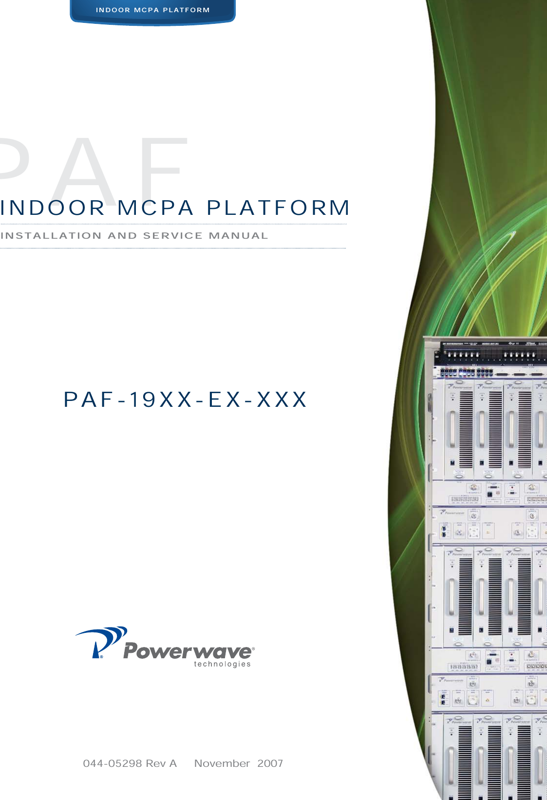
Powerwave Technologies 5JS0098 RF Power Amplifier Frame User Manual 044 05298 PAF 193X EX XXX

Powerwave Technologies Inc RF Power Amplifier Frame 044 05298 PAF 193X EX XXX

Contents

Users Manual 1

044-05298 Rev A     November  2007               INDOOR MCPA PLATFORMINSTALLATION AND SERVICE MANUALPAFINDOOR MCPA PLATFORMPAF-19XX-EX-XXX
© 2007 Powerwave Technologies Incorporated. All rights reserved.Powerwave Technologies, and the Powerwave logo are registered trademarks.This Powerwave product is intended only for installation in a RESTRICTED ACCESS LOCATION and is designed to operate within the Normal Operating (typical operating) ranges or conditions specified in this document. Operation of this equipment beyond the specified ranges in this document may cause:1. Spurious emissions that violate regulatory requirements.2. The equipment to be automatically removed from service when maximum thresholds are exceeded.3. The equipment to not perform in accordance with its specifications. It is the Operator's responsibility to ensure this equipment is properly installed and operated within Powerwave operat-ing specifications to obtain proper performance from the equipment and to comply with regulatory requirements.For PERMANENTLY CONNECTED EQUIPMENT, a readily accessible disconnect device shall be incorporated in the building installation wiring.
PAF-19XX-EX-XXX Warnings, Cautions, and Notes044-05298 Rev A iWarnings, Cautions, and NotesWarnings, Cautions, and Notes are found throughout this manual where applicable. The associated icons are used to quickly identify a potential condition that could result in the consequences described below if precautions are not taken. Notes clarify and provide additional information to assist the user.WARNING: This warning symbol means danger. You are in a situation that could cause bodily injury. Before you work on any equipment, be aware of the hazards involved with electrical and RF circuitry and be familiar with standard practices for preventing accidentsCAUTION: This caution symbol means reader be careful. In this situation, the user might do something that could result in equipment damage or loss of data.NOTE This note symbol means reader take note. Notes contain helpful suggestions or references to material not covered in the document. Procedures are not contained in notes.
Revision Record PAF-19XX-EX-XXXii 044-05298 Rev ARevision Record Revision Letter  Date of Change Reason for ChangeA November 2007 Initial release
044-05298 Rev A iTable of ContentsChapter 1 - Product DescriptionIntroduction ................................................................................................................................................... 1-1Scope of Manual  ........................................................................................................................................... 1-1Product Description ....................................................................................................................................... 1-1Functional And Physical Specifications  ........................................................................................................ 1-1Chapter 2 - Controls and IndicatorsIntroduction ................................................................................................................................................... 2-1Subrack ......................................................................................................................................................... 2-1Ethernet Connector Pinout  ..................................................................................................................... 2-2RS-485 Interface  .................................................................................................................................... 2-3Filter I/O (if used) .................................................................................................................................... 2-3MCPA ............................................................................................................................................................ 2-3Filter (if used)  ................................................................................................................................................ 2-4Circuit Breaker Panel  .................................................................................................................................... 2-6Chapter 3 - InstallationIntroduction ................................................................................................................................................... 3-1Site Survey .................................................................................................................................................... 3-1Space Requirements  .................................................................................................................................... 3-1Unpacking and Inspection ............................................................................................................................. 3-1Electrical Service Recommendations  ........................................................................................................... 3-1Cooling Requirements  .................................................................................................................................. 3-2Installation Instructions  ................................................................................................................................. 3-2PAF ......................................................................................................................................................... 3-2Seismic Brace (Optional) ........................................................................................................................ 3-3DC Connections  ..................................................................................................................................... 3-3RS-485 Alarm Interface  .......................................................................................................................... 3-5MCPA ..................................................................................................................................................... 3-5Initial Start-Up and Power Setting Procedures  ............................................................................................. 3-6Initial Start Up  ......................................................................................................................................... 3-6Chapter 4 - MaintenanceIntroduction ................................................................................................................................................... 4-1Periodic Maintenance  ................................................................................................................................... 4-1Troubleshooting ............................................................................................................................................ 4-1Clearing Alarm Faults  ............................................................................................................................. 4-2System Component Part Numbers  ............................................................................................................... 4-2Field Replacement Procedures ..................................................................................................................... 4-2MCPA ..................................................................................................................................................... 4-3Subrack Cooling Fans  ............................................................................................................................ 4-4Inside Mount  .................................................................................................................................... 4-4Rear Mount  ...................................................................................................................................... 4-5Fan Inside Mount to Rear Mount Conversion  .................................................................................. 4-6Subrack .................................................................................................................................................. 4-7Filter ........................................................................................................................................................ 4-8Circuit Breaker Panel .............................................................................................................................. 4-9Return For Service Procedures  .................................................................................................................. 4-10Obtaining An RMA ................................................................................................................................ 4-10Repackaging For Shipment  .................................................................................................................. 4-10Chapter 5 - SpecificationsIntroduction ................................................................................................................................................... 5-1
PAF-19XX-EX-XXX List of Tablesii 044-05298 Rev AList of Tables2-1 Subrack Faceplate Interface Connectors, and Indicators ........................................................................ 2-22-2 Ethernet Connector Pinout....................................................................................................................... 2-22-3 RS-485 Pinout.......................................................................................................................................... 2-32-4 MCPA Indicators and Controls................................................................................................................. 2-42-5 Filter Connector Descriptions................................................................................................................... 2-53-1 Sample of DC Cable Ratings ................................................................................................................... 3-23-2 PAF Frame Installation Procedure........................................................................................................... 3-33-3 DC Power Installation Procedure............................................................................................................. 3-43-4 RS-485 Alarm States ............................................................................................................................... 3-53-5 MCPA Installation Procedure................................................................................................................... 3-63-6 Initial Startup Procedure .......................................................................................................................... 3-64-1 Periodic Maintenance .............................................................................................................................. 4-14-2 Troubleshooting ....................................................................................................................................... 4-24-3 System Components Part Number List.................................................................................................... 4-24-4 MCPA Removal and Replacement Procedure......................................................................................... 4-34-5 Inside Mount Cooling Fan Removal and Replacement Procedure .......................................................... 4-44-6 Rear Mount Cooling Fan Removal and Replacement Procedure............................................................ 4-54-7 Fan Conversion Procedure ...................................................................................................................... 4-64-8 Subrack Removal and Replacement Procedure...................................................................................... 4-74-9 Filter Removal and Replacement Procedure ........................................................................................... 4-84-10 Circuit Breaker Panel Removal and Replacement Procedure ............................................................... 4-95-1 System Specifications.............................................................................................................................. 5-1
List of Figures PAF-19XX-EX-XXX044-05298 Rev A iiiList of Figures1-1 System Block Diagram ............................................................................................................................ 1-21-2 PAF System Model .................................................................................................................................. 1-21-3 Subrack.................................................................................................................................................... 1-31-4 MCPA ...................................................................................................................................................... 1-31-5 Filter (if used)........................................................................................................................................... 1-31-6 Circuit Breaker Panel............................................................................................................................... 1-42-1 Subrack Interface Panel Connectors ....................................................................................................... 2-12-2 Subrack Rear +27 VDC Connector Block................................................................................................ 2-12-3 MCPA Controls and Indicators ................................................................................................................ 2-32-4 Filter Front Connections .......................................................................................................................... 2-42-5 Filter Front Plate Indicators...................................................................................................................... 2-52-6 Circuit Breaker Panel Front and Top View .............................................................................................. 2-63-1 Frame Installation .................................................................................................................................... 3-33-2 Power Connections.................................................................................................................................. 3-43-3 Return Bus connection ............................................................................................................................ 3-43-4 Frame to Halo Ground Connection Example........................................................................................... 3-53-5 MCPA Front Panel Features.................................................................................................................... 3-64-1 MCPA Removal and Replacement .......................................................................................................... 4-34-2 Inside Mount Cooling Fan Removal and Replacement ........................................................................... 4-44-3 Rear Mount Cooling Fan Removal and Replacement ............................................................................. 4-54-4 Fan Inside Mount to Rear Mount Conversion .......................................................................................... 4-64-5 Subrack Removal and Replacement ....................................................................................................... 4-74-6 Filter Removal and Replacement ............................................................................................................ 4-84-7 Breaker Panel Unit Removal and Replace .............................................................................................. 4-9
PAF-19XX-EX-XXXiv 044-05298 Rev AThis page intentionally left blank
044-05298 Rev A 1-1Chapter 1Product DescriptionIntroductionThis manual contains information and procedures for installation, operation, and maintenance of the PAF-19XX-EX-XXX Multi-Carrier Power Amplifier (MCPA) Indoor System. The manual is organized into chapters as follows.Scope of ManualThis manual is intended for use by service technicians familiar with similar types of equipment. It contains service information required for the equipment described and is current as of the printing date. Changes which occur after the printing date may be incorporated by a complete manual revision or alternatively as additions.Product DescriptionThe PAF-19XX-EX-XXX system, shown in the Figure 1-1 block diagram, is an 1900 MHz, 4-way combined, frame-mounted BTS solution. The PAF system contains three MCPA subracks, each capable of containing up to four MCPAs, three filters, and one DC circuit breaker panel. The MCPA subrack, shown in Figure 1-3, contains linear, feed-forward MCPAs that operate in the 1930 - 1990 MHz range. Each subrack is also equipped with automatic power control (APC), an ethernet connection, an RS-485/RS-232 connection, a filter I/O port, and two cooling fans. The subrack is installed on sliding rails so that it can be pulled forward to allow access to the rear of the subrack.The MCPA, shown in Figure 1-4, is a 1900 MHz module that produces a typical output of 160 watts (52.0 dBm) before system losses, with an instantaneous bandwidth of 25 MHz. The filter assembly, shown in Figure 1-5, if used, supresses unwanted signals and non-linear components of the signal from the amplifiers.The circuit breaker panel, shown in Figure 1-8, consists of two +27 VDC input buses (A and B), and a system circuit breaker panel. The panel receives +27 VDC from the BTS and then distributes circuit breaker protected DC power to the individual subracks.Functional And Physical SpecificationsPAF-19XX-EX-XXX system functional and physical specifications are listed in Chapter 5.❑Chapter 1 - Product Description❑Chapter 2 - Controls and Indicators❑Chapter 3 - Installation❑Chapter 4 - Maintenance❑Chapter 5 - Specifications
PAF-19XX-EX-XXX Functional And Physical Specifications1-2 044-05298 Rev AFigure 1-1   System Block Diagram Figure 1-2   PAF System ModelInput Combiner/Splitter Combiner FilterMCPA-0MCPA-1MCPA-2MCPA-3AnalogInputDigitalInputMain to/from Antenna (T X / R X)Diversity from Antenna (RX)Analog 1 (Main) to BTSAnalog 2 (Main)  to  BTSDigital 1 (Main) to BTSDigital (Main) to BTSDC PowerController2 Analog 1 (Diversity) to BTSAnalog 2 (Diversity)  to  BTSDigital 1  (Diversity) to BTSDigital (Diversity) to BTS2 OFFPC I/O850 MHzSTATUSRESETONAlcatel LucentOFFPC I/O850 MHzSTATUSRESETONAlcatel LucentOFFPC I/O850 MHzSTATUSRESETONAlcatel LucentOFFPC I/O850 MHzSTATUSRESETONAlcatel LucentOFFPC I/O850 MHzSTATUSRESETONAlcatel LucentOFFPC I/O850 MHzSTATUSRESETONAlcatel LucentOFFPC I/O850 MHzSTATUSRESETONAlcatel LucentOFFPC I/O850 MHzSTATUSRESETONAlcatel LucentOFFPC I/O850 MHzSTATUSRESETONAlcatel LucentOFFPC I/O850 MHzSTATUSRESETONAlcatel LucentOFFPC I/O850 MHzSTATUSRESETONAlcatel LucentOFFPC I/O850 MHzSTATUSRESETONAlcatel Lucent
Functional And Physical Specifications PAF-19XX-EX-XXX044-05298 Rev A 1-3Figure 1-3   SubrackFigure 1-4   MCPA Figure 1-5   Filter (if used)Front RearOFFPC I/O850 MHzSTATUSRESETONAlcatel LucentOFFPC I/O850 MHzSTATUSRESETONAlcatelLucentOFFPC I/O850 MHzSTATUSRESETONAlcatel LucentOFFPC I/O850 MHzSTATUSRESETONAlcatelLucentRearFrontSTATUSRESETONOFFPC I/OAlcatel Lucent850 MHz
PAF-19XX-EX-XXX Functional And Physical Specifications1-4 044-05298 Rev AFigure 1-6   Circuit Breaker Panel
044-05298 Rev A 2-1Chapter 2Controls and IndicatorsIntroductionThis chapter contains descriptions of the PAF-19XX-EX-XXX subrack, MCPA, filter, and circuit breaker panel interface connections, controls and indicators. Subrack The location of the subrack interface controls, connectors, and indicator are shown in Figures 2-1 and 2-2 and feature descriptions are listed in Table 2-1.Figure 2-1  Subrack Interface Panel ConnectorsFigure 2-2  Subrack Rear +27 VDC Connector Block RF OUTETHERNET  RS485 FILTER I/O CDMA1 CDMA2 CDMA3 CDMA4 CDMA5 CDMA6DIGITALDC POWER+27VRETURN01230123
Subrack PAF-19XX-EX-XXX2-2 044-05298 Rev AEthernet Connector PinoutThe Ethernet port is used for commuication with a personal computer (PC) or with a base station. The pin layout for the Ethernet interface is listed in Table 2-2.Table 2-1  Subrack Faceplate Interface Connectors, and IndicatorsConnectors DescriptionRFDIGITAL (CDMA1 through CDMA6)Six SMA input connectors RF OUTPUT  7/16 DIN connector, composite transmit signal output.StatusETHERNET RJ-45 connector used for host alarm reporting, Pin layout is listed in Table 2-2RS-232/RS-485 DB-9 connector used for host alarm reporting. Pin Layout is listed in Table 2-3FilterFilter I/O DB-15 connector to provide control and communication to filter (if used)DC Power+27 VDC Connector Block (Rear of Subrack)Provide connections for +27 VDC circuit breaker protected power from breaker panel and frame ground bus return connections. Table 2-2  Ethernet Connector PinoutPin Description1Transmit Data (TX) +2 Transmit Data (TX) -3Receive Data (RX) +4NC5NC6 Receive Data (RX) -7NC8NC
PAF-19XX-EX-XXX MCPA044-05298 Rev A 2-3RS-485 InterfaceThis RS-485 connector is used for serial communication and as an interface to the system for delivery of alarms. Grounding pin 8 disables RS-485 communication. Table 2-3 lists the pin descriptions.Filter I/O (if used)This port is used for communication with the filter tray associated with the subrack.MCPAThe controls and indicators for the MCPA consist of an OFF/ON/RESET switch and tri-color LED status indicator as shown in Figure 2-3 with detailed functions listed in Table 2-2.Figure 2-3  MCPA Controls and IndicatorsTable 2-3  RS-485 PinoutPin Description1RS-485 RX+2N/C3N/C4 RS-485 RX-5Ground6 RS-485 TX-7RS-485 TX+8 Select = 1 (Not grounded)9GroundMulti-ColorStatus LED3-PositionSwitch:RESETONOFFRJ-11ConnectorAlcatel LucentSTATUSRESETONOFFPC I/O850 MHz
Filter (if used) PAF-19XX-EX-XXX2-4 044-05298 Rev AFilter (if used)Figure 2-4 shows the front plate of the filter. Table 2-3 lists the descriptions of the connectors. Figure 2-5 shows the five indicators on the filter front panel. The LED will display a green light during normal operation and red light if the indicated stage has suffered a catastrophic failure.Figure 2-4  Filter Front ConnectionsTable 2-4  MCPA Indicators and ControlsControl/Indicator DescriptionSTATUS (Multi-colored LED Indicator)LED Color MCPA Status.Green (solid) RF enabled, OFF/ON/RESET switch set to ON (middle position).Green (blinking) Standby.Yellow (solid) Major AlarmYellow (blinking) APC ActivatedRed (solid) Critical Alarm, MCPA disabled.Red (blinking) Over Temperature AlarmRed/Yellow (blinking together) High Reverse Output Power 1 minute validation periodRed/Yellow (alternating) Critical Alarm during remote firmware download or checksum failureToggle Switch positions: RESET (Up)ON (Middle)OFF (Down)Resets MCPA. LED indicates boot mode, then turns solid green.Enables MCPA. LED indicates solid green.Disables MCPA. LED Indicates solid red.RJ-11  RS-232 PC Interface for factory use only.Antenna Main Antenna DiversityMCPA RF Out DC PowerCDMA 1Main Antenna Receive LNA Output PortsCDMA 1Diversity Antenna Receive LNA output portForward Main Power Coupler PortRF Test PortCDMA 2 CDMA 2IIC
PAF-19XX-EX-XXX Filter (if used)044-05298 Rev A 2-5Figure 2-5  Filter Front Plate IndicatorsTable 2-5  Filter Connector DescriptionsConnector/Cable DescriptionAntenna ConnectionsAntenna Main 7/16 connector - Dx0 (bi-directional) antenna portAntenna Diversity 7/16 connector - Dx1 (simplex RX) antenna portSubrack ConnectionMCPA RF Out 7/16 connector - connects subrack to receive output signalIIC DB-15 connector for communication between filter and subrackBTS ConnectionsCDMA 1 Dx0 Receive LNA Output Port CDMACDMA 2 Dx0 Receive LNA Output Port CDMADx0 Receive LNA Input Port AMPSDx0 Receive LNA Output Port AMPSCDMA 1 Dx1 Receive LNA Output Port CDMACDMA 2 Dx1 Recevie LNA Output Port CDMADx1 Receive LNA Output Port AMPSDx1 Receive LNA Output Port AMPSTest Port ConnectionsRF Test Port SMA connector - Switched Coupler Port (4-way)Forward Main Coupler Port SMA connector - Dx0 Forward Power Coupler PortPower ConnectionPower Power connectionDC PowerIICLNA DX1DX0RFONTTLNA
Circuit Breaker Panel PAF-19XX-EX-XXX2-6 044-05298 Rev ACircuit Breaker Panel Figure 2-6 shows the switches on the front of the breaker panel and the cable connections on the rear. Chapter 3 discusses power cable connection. Figure 2-6  Circuit Breaker Panel Front and Top ViewOFF OFF OFF OFF OFF OFF OFF OFF OFF OFF OFF OFF OFF OFFONIONIONIONIONIONIONIONIONIONIONIONIONIONIAMP 0 AMP 2 AMP 0 AMP 2 AMP 0 AMP 2 AMP 1 AMP 3 AMP 1 AMP 3 AMP 1 AMP 3DIV 0 DIV 1LOWEST SUBRACK LOWEST SUBRACKSECTOR 0 SECTOR 1 SECTOR 2ALPHA BETA GAMMA SECTOR 0 SECTOR 1 SECTOR 2ALPHA BETA GAMMAFILTERS FILTERSAlcatel LucentTop
044-05298 Rev A 3-1Chapter 3InstallationIntroductionThis chapter contains unpacking, inspection, installation instructions, and recommendations for installing the PAF-19XX-EX-XXX MCPA Indoor System.Site SurveyPowerwave recommends that a site survey be performed prior to equipment ordering or installation. Performing a detailed site survey reduces or eliminates installation and turn-up delays. Pay particular attention to AC or DC power availability, cooling needs, floor space, and RF/DC cabling/breaker requirements. See Chapter 5 for system dimensions and weights.Space RequirementsThe PAF system requires the following floor space for clearance (W x D x H): 28.5 inches (724 mm) x 78.2 inches (1986 mm) x 38.5 inches (978 mm). To properly service the system, an additional 48 inches (1220 mm) is required in the front of the unit. To permit proper airflow, allow a minimum of 8.27 inches (210 mm) behind the PAF.Unpacking and InspectionThis equipment has been operated, tested and calibrated at the factory. Carefully open the containers and remove the equipment. Retain all packing material that can be reassembled in the event that the unit must be returned to the factory. Please perform the following steps:❑Visually inspect equipment for damage that may have occurred during shipment. If possible, in the presence of the delivery person. ❑Check for evidence of water damage, bent or warped chassis, loose screws or nuts, or extrane-ous packing material in connectors.If the equipment is damaged, file a claim with the carrier once the extent of any damage is assessed. If the equipment must be returned to the factory, contact the factory for a Return Material Authorization (RMA) as described in Chapter 4.Electrical Service RecommendationsProper AC line conditioning and surge suppression is necessary on the primary AC input to the +27 VDC power source. Powerwave recommends that all electrical service be installed in accordance with the National Electrical Code (NEC) and any applicable state or local codes.Table 3-1 lists a sample of DC cable ratings.
Cooling Requirements PAF-19XX-EX-XXX3-2 044-05298 Rev ACooling RequirementsEach MCPA at full power generates the BTUs per hour listed in Table 3-3. A 1-ton air conditioner offsets 12,000 BTUs of heat. The MCPA operates within the temperature environment specified in Chapter 5.Fan speed is dependent on MCPA operating temperature. The fans remain off until the MCPAs exceed +43°C base plate temperature. Once enabled, the fan remains on until all MCPA base plate temperatures are below +41°C. Installation InstructionsInstall the PAF frame, DC and RF connections, alarms, and MCPAs as described in the following paragraphs.PAF To install the PAF frame, perform the instructions in Table 3-4.Table 3-1  Sample of DC Cable RatingsAWGorMCM mm2Copper3 Conductor In Raceway Single Conductor In Free Air75°C 90°C 110°C 75°C90°C110°C10 540 45 50 55 658 8 57 55 60 70 75 85613 76 70 80 95 100 1204 21 101 95 105 125 135 160234 135 125 135 170 185 2101 42 158 145 160 195 215 245053 183 165 190 230 250 28500 67 212 195 265 300000 85 245 225 310 3500000 107 287 260 360 405MCM250 127 320 290 405 455MCM300 152 359 320 445 505Based on ambient temperature of 30×C (86×F)100% Load Factor Source: Industrial Electric Wire & Cable Inc., Technical Guide Vol. 4M 11/99, Table III Suggested Ampacities - All Types of Insulations; Based on National Electric CodeCAUTION: The PAF frame, as factory shipped, weighs approximately 250 lbs (113 kg) to 428 lbs (194 kg) depending on configuration (MCPAs not included). During unpacking and installation, be careful with the semi-rigid cables. Protect the cables from damage by avoiding contact with doorways or other equipment. Do not use the cables as handles for moving the components or the frame.NOTE Reuse shipping pallet washers to secure PAF to installation site floor.
PAF-19XX-EX-XXX Installation Instructions044-05298 Rev A 3-3Figure 3-1  Frame InstallationSeismic Brace (Optional)The PAF system meets GR-63-CORE, Section 4.4.1, Zone 4 compliance. If additional bracing is required, Powerwave offers an optional seismic brace kit for those circumstances. Please contact a Powerwave sales representative for additional information and assistance.DC ConnectionsConnect and verify DC power cables between the BTS power plant and the PAF system circuit breaker panel and PAF return bus located at the top of the PAF as instructed in Table 3-5. Required power is +27 VBC, and each power input is directly connected through the circuit breaker in the front of the panel to the power output directly below it in the panel.Table 3-2  PAF Frame Installation ProcedureStep Action1. Set PAF frame in planned location2. Mark floor drill holes on floor where lag bolts will be installed. Move frame to side. Refer to lag bolt manufacturer’s instructions for hole depth and diameter3. Move frame back over drilled holes4. Use a level to ensure frame is not leaning. Insert shims between frame base and floor to level frame. Shims should wrap around lag bolts as shown in Figure 3-25. Secure frame in place with red eye lag bolts and appropriate washersWARNING: Turn off external DC power before connecting DC power cables.ConcreteLag AnchorShimCabinetFlat WasherLock WasherLag Bolt
Installation Instructions PAF-19XX-EX-XXX3-4 044-05298 Rev AFigure 3-2  Power ConnectionsFigure 3-3  Return Bus connectionTable 3-3  DC Power Installation ProcedureStep Action1. Remove circuit breaker panel top protective cover2. Connect fourteen individual red power cables, one to each input on the upper row of connections. (designated Row A Figure 3-2)3. Attach opposite ends of red MCM 250 powr cables to power plant’s main DC bus bar after main shunt.4. Insert fourteen individual black power cables into front of yellow and green ground connections as shown in Figure 3-3 and tighten screws5. Attach opposite ends of black power cables to power plant's main DC return bus bar6. Connect PAF frame to halo grounding system at frame top (four locations) using green 6 AWG cable as shown in Figure 3-47. Reinstall circuit breaker panel top protective cover.8. Affix supplied ground sticker directly beneath one utilized frame grounding points shown in Figure 3-4Row ARow BGround Return Connections
PAF-19XX-EX-XXX Installation Instructions044-05298 Rev A 3-5Figure 3-4  Frame to Halo Ground Connection ExampleRS-485 Alarm Interface The RS-485 alarm interface provides the BTS controller with system status via a 1 byte protocol. The baud rate is fixed at 15.6 K. Table 3-6 lists the available alarm states.MCPAInstall the MCPAs as instructed in Table 3-7.NOTE DO NOT remove metallic tape at frame top when connecting to Halo ground system. Removing tape voids PAF frame warranty. Table 3-4  RS-485 Alarm StatesAlarmState DefinitionNo AlarmMinor Alarm Any or all fans failMajor Alarm Any one MCPA module disabledCritical All MCPA modules disabledCAUTION: Slowly insert MCPA into subrack. Forcing MCPA into subrack may cause pins on the MCPA D-sub connector to become recessed or broken.GroundStickerTo HaloGroundTo HaloGroundMetallicTape
Initial Start-Up and Power Setting Procedures PAF-19XX-EX-XXX3-6 044-05298 Rev AFigure 3-5  MCPA Front Panel FeaturesInitial Start-Up and Power Setting ProceduresThe following paragraphs provide initial startup, and power setting procedures.Initial Start UpTo complete initial startup, perform the instructions listed in Table 3-8.Table 3-5  MCPA Installation ProcedureStep Action1. Inspect MCPA 21-pin connector. Verify all pins are straight, no pins are recessed, and alignment shield is not bent2. Set MCPA power OFF/ON/RESET switch to OFF3. Rotate MCPA quarter-turn fasteners counter-clockwise to unlock position shown in Figure 3-84. Install MCPA(s) into subrack. To secure each MCPA, rotate quarter-turn fasteners clockwise to lock position as shown in Figure 3-8CAUTION: Excessive input power may damage MCPA. Before applying power, ensure MCPA inputs and outputs are properly terminated at 50 ohms. Do not operate MCPA without a load attached. Refer to Chapter 5 for input power requirements. Table 3-6  Initial Startup ProcedureStep Action1. Verify all input and output cables are properly connected2. Turn on +27 VDC supply to MCPA3. Set all MCPA front panel OFF/ON/RESET switches to ON (middle) position4. Allow MCPAs to warm up for at least two minutes before taking power readingsUnlocked LockedLED StatusIndicatorRF Switch:RESETONOFF Quarter-TurnFastenersONOFFONOFFAlcatel LucentAlcatel Lucent

Navigation menu