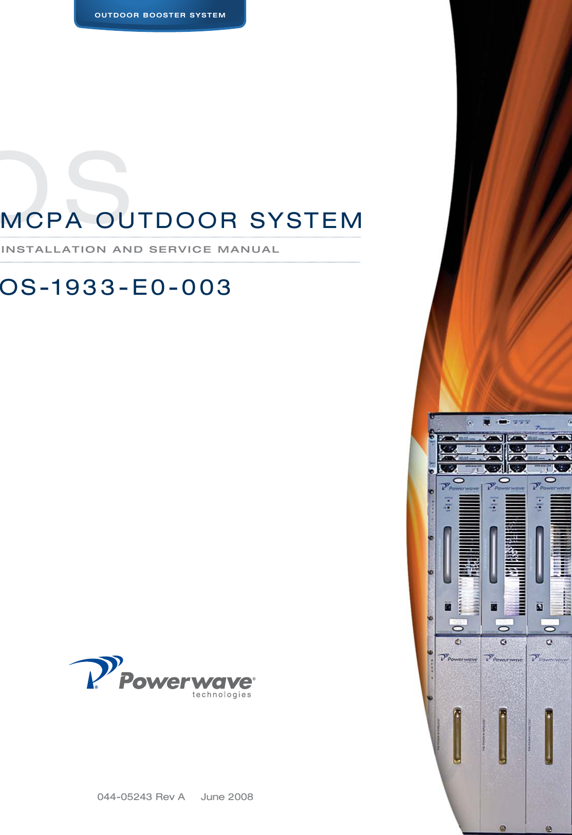
Powerwave Technologies 5JS0105 Booster Amplifier Assembly User Manual 044 05243 OS 1933 E3 003 Rev A
Powerwave Technologies Inc Booster Amplifier Assembly 044 05243 OS 1933 E3 003 Rev A
Contents
- 1. Users Manual Part 1
- 2. Users Manual Part 2
- 3. Users Manual Part 3
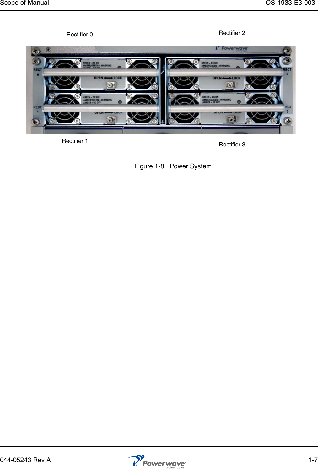
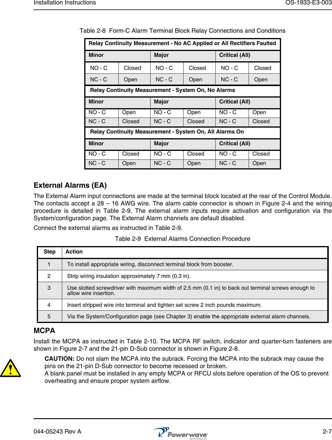
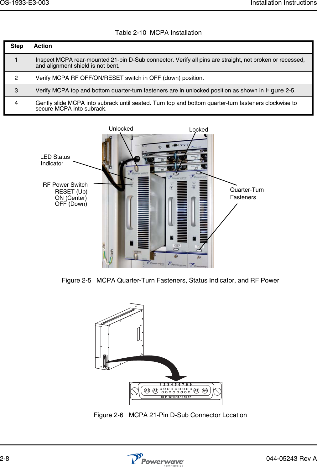
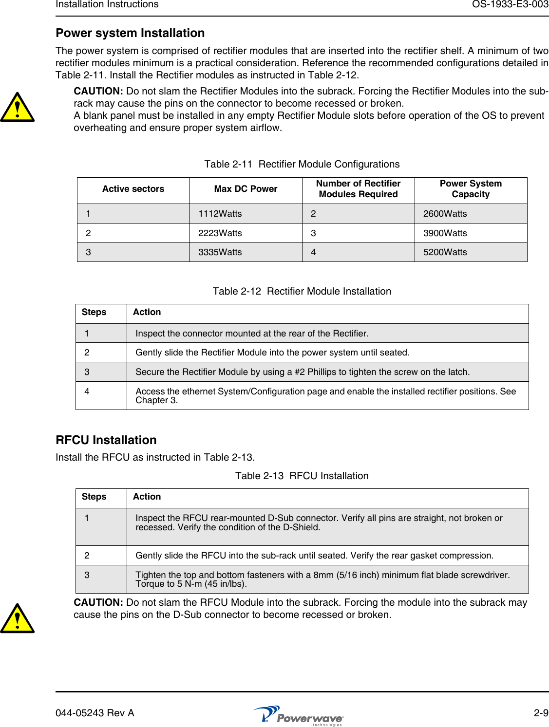
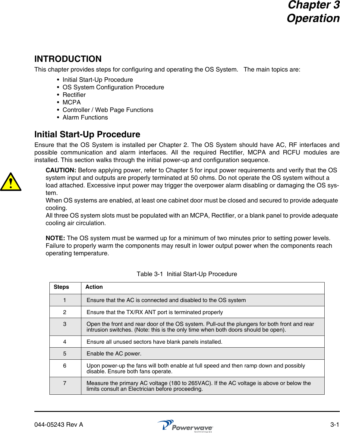
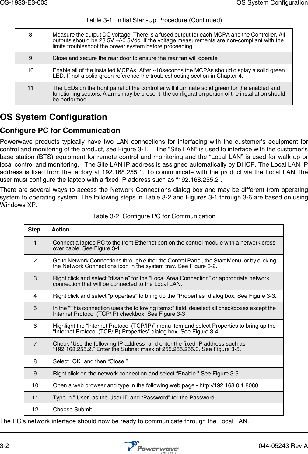
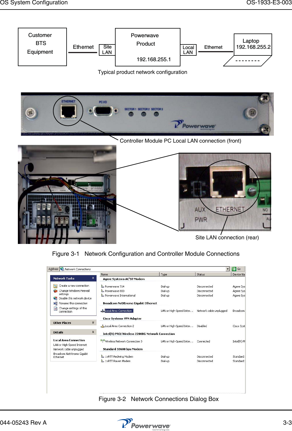
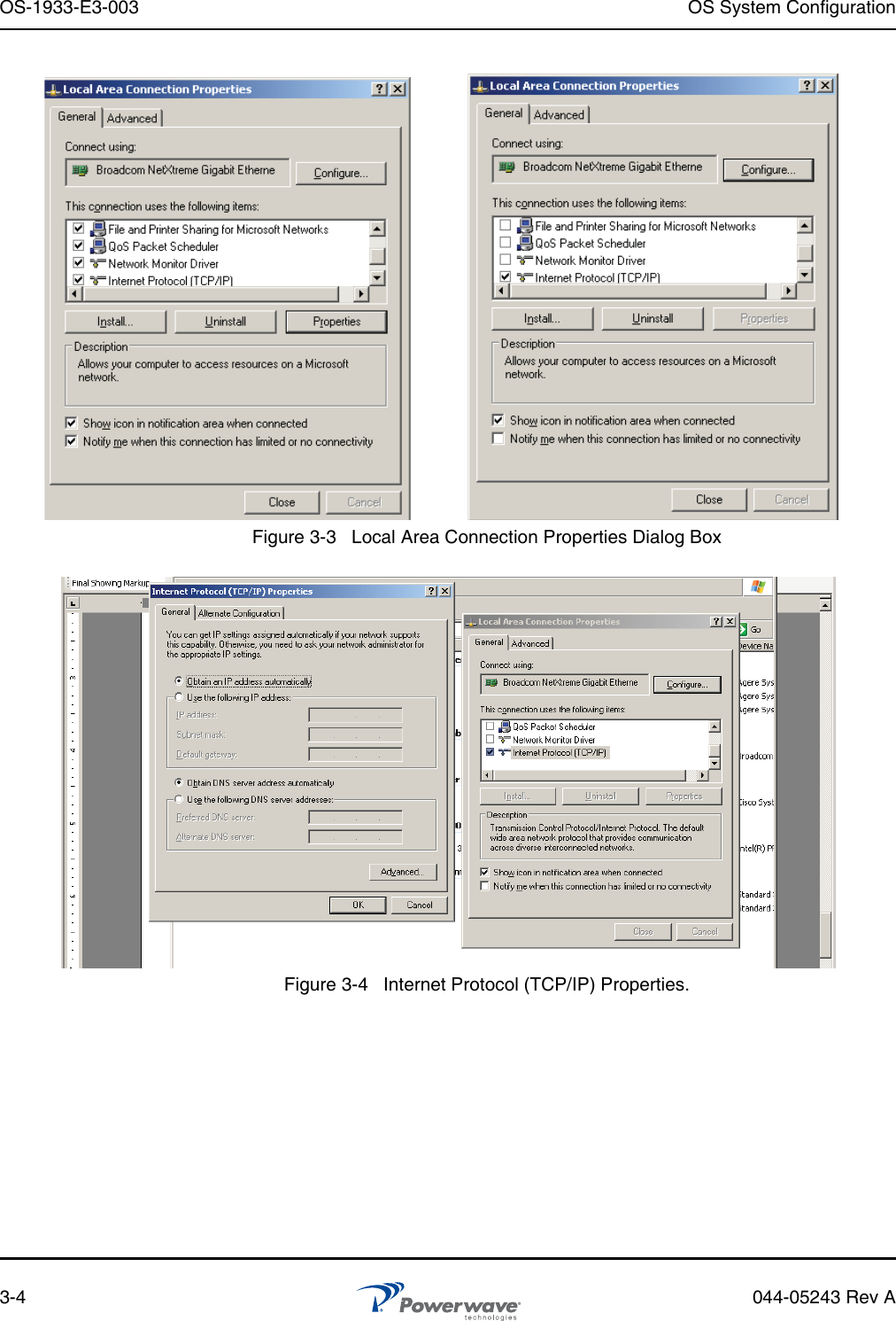
Users Manual Part 1