Powerwave Technologies 5JS0106 Nexus RT Digital Repeater User Manual 044 05311 Nexus RT
Powerwave Technologies Inc Nexus RT Digital Repeater 044 05311 Nexus RT
Users Manual
COVERAGE SYSTEMS
INSTALLATION AND SERVICE MANUAL
NEXUS RT REPEATER
044-05311 REV. A OCTOBER 2 0 0 8

© 2008 Powerwave Technologies Incorporated. All rights reserved.
Powerwave Technologies and the Powerwave logo are registered trademarks.
Powerwave Technologies Inc. reserves the right to make changes to documentation and equipment, including but not
limited to component substitution and circuitry changes. Changes that impact this document may be subsequently
incorporated in a later revision of this document.
This Powerwave product is designed to operate within the Normal Operating (typical operating) ranges or conditions
specified in this document. Operation of this equipment beyond the specified ranges in this document may cause (1)
spurious emissions that violate regulatory requirements; (2) the equipment to be automatically removed from service
when maximum thresholds are exceeded; or (3) the equipment to not perform in accordance with its specifications. It is
the Operator's responsibility to ensure this equipment is properly installed and operated within Powerwave operating
specifications to obtain proper performance from the equipment and to comply with regulatory requirements.
The rated output power of a Nexus RT is for multiple carriers. As long as the composite power does not exceed the
rated power (28 dBm for North America), derating is not required for multiple carriers. For situations where regulatory
requirements require reduced interference to adjacent band users, the rating would have to be reduced by 3 dB. This
power reduction is to be by means of input power or gain reduction and not by an attenuator at the output of the device.
Input power is rated at 115/230VAC, 50/60Hz, and should be protected based on the power and fuse specifications in
Chapter 5 of this manual. Power strips should, at a minimum, conform to this requirement to prevent equipment dam-
age and possible overload.
Federal Communications Commission (FCC)
This device complies with the technical standards governing mobile radio devices in accordance with FCC Rules. This
device is intended to facilitate the transmission of mobile radio devices in the cellular and PCS services, and its opera-
tion by end users or others requires carrier consent under FCC rules. This equipment has been tested and found to
comply with the limits for a Class A digital device, pursuant to CRF47 part 15 of the FCC rules. This equipment is also
certified to CRF47 part 22 (cellular) and part 24 (PCS) of the FCC Rules depending on the band of operation. Changes
or modifications not expressly approved by PowerwaveTechnologies, Inc. for compliance could void the user’s author-
ity to operate this equipment. These limits are designed to provide reasonable protection against harmful interference
when the equipment is operated in a commercial environment.This equipment generates, uses, and can radiate radio
frequency energy and, if not installed and used in accordance with the instruction manual, may cause harmful interfer-
ence to radio communications. Operation of this equipment in a residential area is likely to cause harmful interference
in which case the user will be required to correct the interference at his own expense.
Industry Canadian Requirements
All Powerwave apparatus introduced in the Canadian market meet all requirements of the Canadian Interference-Caus-
ing Equipment Regulations. The -20dB bandwidth at Downlink at 1900 MHz band is 61 MHz. The -20dB bandwidth at
Uplink at 1900 MHz band is 61.2 MHz. The -20dB bandwidth at Downlink at 850 MHz is 27 MHz. The -20dB bandwidth
at uplink at 850 MHz is 27 MHz. The output impedance of the unit referenced in this document is 50 Ohms. The Manu-
facturer's rated output power of this equipment is for single carrier operation. For situations when multiple carrier sig-
nals are present, the rating would have to be reduced. This power reduction is to be by means of input power or gain
reduction and not by an attenuator at the output of the device. The input signal is optical so input impedance require-
ments are not applicable.
Powerwave Technologies Inc., 1801 East St. Andrew Place, CA 92705 Santa Ana, USA.
Phone +1 714 466 1000 – Fax +1 714 466 5800 – Internet www.powerwave.com

Nexus RT Effective Pages
044-05311 Rev A i
Revision Record
Revision Letter Date of Change Reason for Change
AOctober 2008 New (original)

Effective Pages Nexus RT
ii 044-05311 Rev A
This page intentionally left blank
044-05311 Rev A iii
Preface
Warning, Cautions, and Notes
Warnings, Cautions, and Notes are found throughout this manual where applicable. The associated icons in
warnings and cautions are used to quickly identify a potential condition that could result in the consequences
described below if precautions are not taken. Notes clarify and provide additional information to assist the
user.
WARNING: The warning symbol means danger. You are in a situation that could cause bodily
injury or death. Before you work on any equipment, be aware of the hazards involved with elec-
trical and RF circuitry and be familiar with standard practices for preventing accidents.
CAUTION: The caution symbol means the potential exists for equipment damage or loss of data.
NOTE: Notes contain helpful suggestions or references to material not covered in the document.
Safety
Any personnel involved in installation, operation, or service of units included in a Powerwave repeater
systemmust understand and follow the points below:
Powerwave repeaters are designed to receive and amplify signals from one or more base stations and
retransmit the signals to one or more mobile stations. And, also to act the other way round, that is to
receive signals from one or more mobile stations, amplify and retransmit the signals to the base sta-
tions. Powerwave repeater systems must be used exclusively for this purpose and nothing else.
Units supplied from the mains must be connected to grounded outlets and in conformity with the local
prescriptions.
For outdoor use, the power cord should meet at least IP65 encapsulation requirements. Do not turn the
main power on until you are ready to commission the equipment.
Power supply units supplied from the mains contain dangerous voltage that can cause electric shock.
Disconnect the mains prior to any work in such a unit. Local regulations are to be followed when servic-
ing such units. Only authorized service personnel are allowed to service units while the mains are con-
nected.
When working on an a repeater on high ground, for instance on a mast or pole, be careful not to drop
parts or the entire repeater. Falling parts can cause serious personal injury.
All RF transmitting units, including the Nexus RT Repeater, will generate radio signals and thereby
give rise to electromagnetic fields that may be hazardous to the health of any person who is exten-
sively exposed close to an antenna.
Beryllium oxide (BeO) may be contained in power devices, for instance in dummy loads in directional
couplers (DCC), in combiner units (CMB), and in attenuators on the FON board. Beryllium oxide is poi-
sonous if present as dust or smoke that can be inhaled. Do not file, grind, machine, or treat these parts
with acid.
Coaxial cables used in many Powerwave systems have the insulation made of PTFE, polytetrafluoro
ethylene, that gives off small amounts of hydrogen fluoride when heated. Hydrogen fluoride is poison-
ous. Do not use heating tools when stripping off coaxial cable insulation. No particular measures are to
be taken in case of fire because the emitted concentration of hydrogen fluoride is very low.
Electrostatic Discharge (ESD) Nexus RT
iv 044-05311 Rev A
Warning Signs
The following warning signs must be observed and be kept clean and readable.
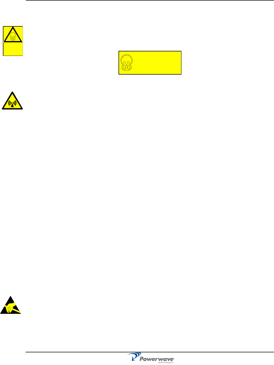
Beryllium oxide
This warning sign to the left is applied to boards and units which contain beryllium oxide parts.
This warning sign below is applied at the bottom, inside the cabinet, below the power supply unit.
Human Exposure to RF Radiation
Safe distances must be kept when working around antennas. The following paragraphs describe the
cautions to be aware of during the installation and maintenance of antenna systems and how to calculate
safety distances needed for RF radiation at different antenna power and frequencies.
Repeater Antennas
To be able to receive and transmit signals, a repeater is connected to a donor antenna directed towards the
base station and a service antenna directed towards the coverage area. A fiber optic cable from the base
station might, however, be substituted for the donor antenna.
Installation and Maintenance of Antenna Systems
Installation and maintenance of all antenna systems must be performed with respect to the radiation
exposure limits for public areas. The antenna radiation level is affected by the output power, antenna gain,
and transmission devices such as cables, connectors, splitters and feeders. Also have in mind the system
minimum coupling loss, typically between 25dB and 35dB, is determined by a standard with the purpose to
protect base stations from noise and other performance dropping effects.
Radiation Exposure
The World Health Organization (WHO) and International Commission on Non-Ionising Radiation Protection
(ICNIRP) have determined recommendations for radiation exposure. ICNIRP recommends not to exceed
the following radiation power for public exposure:
Frequency Radiation power
800/900 MHz 4.5W/m²
1800/1900 MHz 9.0W/m²
2100 MHz 10.0W/m²
For antennas larger than 20cm the maximum radiation power can be calculated by using the following
formula:
Electrostatic Discharge (ESD)
ESD can severly damage essential parts of the equipment if not handled carefully. Parts on
Printed Circuit Board Assemblies (PCBA) as well as other parts in the equipment are
sensitive to ESD. Never touch the PCBA or uninsulated conductor surfaces unless
absolutely necessary.
If you must handle the PCBAs or uninsulated conductor surfaces, use ESD protective
equipment or first touch the chassis with your hand. Never let your clothes touch PCBAs or
uninsulated conductor surfaces and always store PCBAs in ESD-safe bags.
S= P/(4πr2)
S = Radiation power in W/m²
P = Output power in W
r = Distance between antenna and human in meters
Beryllium
oxide
hazard
BERYLLIUM OXIDE
(Toxic)
used in equipment
see instruction book

Nexus RT List of Acronyms
044-05311 Rev A v
List of Acronyms
AC Alternating Current
ADC Analogue-to-Digital Converter
ALC Automatic Level Control
BTS BaseTransceiver Station
DAC Digital to Analog Converter
dB Decibel
DC Direct Current
DDA Donor Duplexer Assembly
DL Downlink
DPA Donor Power Amplifier
DSP Digital Signal Processor
EEPROM Electrically Erasable Programmable Read Only Memory
EMC ElectroMagnetic Compatibility
EMI ElectroMagnetic Interference
EMS Element Management System
FCC Federal Communications System
FPGA Field Programmable Gate Array
GRL Gain Range Limiting
GSM Global System Mobile
IF Intermediate Frequency
IIP3 3rd Order Input Intercept Point
IMD Intermodulation Distortion
IO Input-Output
IOC Input Overload Control
IP Internet Protocol
JTAG Joint Test Advisory Group Interface (common name for IEEE
Std 1149.1)
LED Light Emitting Diode
LPT Linear Power Transmitter
MHz MegaHertz

List of Acronyms Nexus RT
vi 044-05311 Rev A
MCU Microcontroller Unit
MFLOPs Million Floating Point Operations per second
MHz Mega Hertz
Msps Million of Samples Per Second
MTBF Mean Time Between Failures
MTTR Mean Time to Repair
NEP Network Elerment Processor
NMS Network Management System
OA&M Operations, Administration and Maintenance
OTA Over the Air
PA Power Amplifier
PCS Personal Communications Services
PCBA Printed Circuit Board Assembly
RCM RF Converter Module
RF Radio Frequency
RSSI Receive Signal Strength Indicator
Rx Receive
SNMP Simple Network Management Protocol
SDA Service Duplexer Assembly
SPA Service Power Amplifier
TBD To Be Decided
TX Transmit
UL Uplink; Underwriters Laboratory
USB Universal Serial Bus
VSWR Voltage Standing Wave Ratio
WAN Wide Area Network
WCDMA Wideband Code Division Multiple Access

044-05311 Rev A vii
Table of Contents
Warning, Cautions, and Notes . . . . . . . . . . . . . . . . . . . . . . . . . . . . . . . . . . . . . . . . . . . . . . . . . . . . . . . . . vii
Safety . . . . . . . . . . . . . . . . . . . . . . . . . . . . . . . . . . . . . . . . . . . . . . . . . . . . . . . . . . . . . . . . . . . . . . . . . . . . vii
Human Exposure to RF Radiation . . . . . . . . . . . . . . . . . . . . . . . . . . . . . . . . . . . . . . . . . . . . . . . . viii
Electrostatic Discharge (ESD) . . . . . . . . . . . . . . . . . . . . . . . . . . . . . . . . . . . . . . . . . . . . . . . . . . . . . . . . . viii
List of Acronyms . . . . . . . . . . . . . . . . . . . . . . . . . . . . . . . . . . . . . . . . . . . . . . . . . . . . . . . . . . . . . . . . . . . . . x
Product Description
Introduction . . . . . . . . . . . . . . . . . . . . . . . . . . . . . . . . . . . . . . . . . . . . . . . . . . . . . . . . . . . . . . . . . . . . . . . .1-1
Scope of Manual . . . . . . . . . . . . . . . . . . . . . . . . . . . . . . . . . . . . . . . . . . . . . . . . . . . . . . . . . . . . . . . . . . . .1-1
Overview . . . . . . . . . . . . . . . . . . . . . . . . . . . . . . . . . . . . . . . . . . . . . . . . . . . . . . . . . . . . . . . . . . . . . . . . . .1-1
Chassis Design . . . . . . . . . . . . . . . . . . . . . . . . . . . . . . . . . . . . . . . . . . . . . . . . . . . . . . . . . . . . . .1-2
Indicators and Connectors
Introduction . . . . . . . . . . . . . . . . . . . . . . . . . . . . . . . . . . . . . . . . . . . . . . . . . . . . . . . . . . . . . . . . . . . . . . . .2-1
Indicators . . . . . . . . . . . . . . . . . . . . . . . . . . . . . . . . . . . . . . . . . . . . . . . . . . . . . . . . . . . . . . . . . . . . . . . . .2-1
Connectors . . . . . . . . . . . . . . . . . . . . . . . . . . . . . . . . . . . . . . . . . . . . . . . . . . . . . . . . . . . . . . . . . . . . . . . .2-2
Software and Hardware Compatibility . . . . . . . . . . . . . . . . . . . . . . . . . . . . . . . . . . . . . . . . . . . . . . . . . . .2-2
Installation
Introduction . . . . . . . . . . . . . . . . . . . . . . . . . . . . . . . . . . . . . . . . . . . . . . . . . . . . . . . . . . . . . . . . . . . . . . . .3-1
Site Survey . . . . . . . . . . . . . . . . . . . . . . . . . . . . . . . . . . . . . . . . . . . . . . . . . . . . . . . . . . . . . . . . . . . . . . . .3-1
Unpacking and Inspection . . . . . . . . . . . . . . . . . . . . . . . . . . . . . . . . . . . . . . . . . . . . . . . . . . . . . . . . . . . .3-1
Nexus RT Location . . . . . . . . . . . . . . . . . . . . . . . . . . . . . . . . . . . . . . . . . . . . . . . . . . . . . . . . . . . . . . . . . .3-1
Mounting . . . . . . . . . . . . . . . . . . . . . . . . . . . . . . . . . . . . . . . . . . . . . . . . . . . . . . . . . . . . . . . . . . . . . . . . . .3-2
Mounting the Nexus RT on the Bracket . . . . . . . . . . . . . . . . . . . . . . . . . . . . . . . . . . . . . . . . . . . .3-3
Connections . . . . . . . . . . . . . . . . . . . . . . . . . . . . . . . . . . . . . . . . . . . . . . . . . . . . . . . . . . . . . . . . . . . . . . .3-4
Main Power and Grounding . . . . . . . . . . . . . . . . . . . . . . . . . . . . . . . . . . . . . . . . . . . . . . . . . . . . .3-4
.RF Connections . . . . . . . . . . . . . . . . . . . . . . . . . . . . . . . . . . . . . . . . . . . . . . . . . . . . . . . . . . . . .3-4
Attaching the Sunshield . . . . . . . . . . . . . . . . . . . . . . . . . . . . . . . . . . . . . . . . . . . . . . . . . . . . . . . .3-5
Commissioning . . . . . . . . . . . . . . . . . . . . . . . . . . . . . . . . . . . . . . . . . . . . . . . . . . . . . . . . . . . . . . . . . . . . .3-6
Initial Startup . . . . . . . . . . . . . . . . . . . . . . . . . . . . . . . . . . . . . . . . . . . . . . . . . . . . . . . . . . . . . . . .3-6
Configure the Nexus RT . . . . . . . . . . . . . . . . . . . . . . . . . . . . . . . . . . . . . . . . . . . . . . . . . . . . . . .3-6
Log in . . . . . . . . . . . . . . . . . . . . . . . . . . . . . . . . . . . . . . . . . . . . . . . . . . . . . . . . . . . . . . . . . . . . . .3-6
Maintenance
Introduction . . . . . . . . . . . . . . . . . . . . . . . . . . . . . . . . . . . . . . . . . . . . . . . . . . . . . . . . . . . . . . . . . . . . . . . .4-1
Periodic Maintenance . . . . . . . . . . . . . . . . . . . . . . . . . . . . . . . . . . . . . . . . . . . . . . . . . . . . . . . . . . . . . . . .4-1
Troubleshooting . . . . . . . . . . . . . . . . . . . . . . . . . . . . . . . . . . . . . . . . . . . . . . . . . . . . . . . . . . . . . . . . . . . .4-1
Alarm Faults . . . . . . . . . . . . . . . . . . . . . . . . . . . . . . . . . . . . . . . . . . . . . . . . . . . . . . . . . . . . . . . .4-1
Field Replaceable Units . . . . . . . . . . . . . . . . . . . . . . . . . . . . . . . . . . . . . . . . . . . . . . . . . . . . . . . . . . . . . .4-2
Return For Service Procedures . . . . . . . . . . . . . . . . . . . . . . . . . . . . . . . . . . . . . . . . . . . . . . . . . . . . . . . .4-2
Obtaining an RMA . . . . . . . . . . . . . . . . . . . . . . . . . . . . . . . . . . . . . . . . . . . . . . . . . . . . . . . . . . . .4-2
Repackaging for Shipment . . . . . . . . . . . . . . . . . . . . . . . . . . . . . . . . . . . . . . . . . . . . . . . . . . . . .4-2
Specifications
Introduction . . . . . . . . . . . . . . . . . . . . . . . . . . . . . . . . . . . . . . . . . . . . . . . . . . . . . . . . . . . . . . . . . . . . . . . .5-1

CUS-0361A-59 Rev B iii
List of Figures
1-1 Nexus RT Block Diagram . . . . . . . . . . . . . . . . . . . . . . . . . . . . . . . . . . . . . . . . . . . . . . . . . . . . . . . . .1-2
1-2 Nexus RT Repeater Enclosure . . . . . . . . . . . . . . . . . . . . . . . . . . . . . . . . . . . . . . . . . . . . . . . . . . . .1-2
1-3 Nexus RT Dual Slice Configuration . . . . . . . . . . . . . . . . . . . . . . . . . . . . . . . . . . . . . . . . . . . . . . . . .1-3
1-4 Nexus RT Connections . . . . . . . . . . . . . . . . . . . . . . . . . . . . . . . . . . . . . . . . . . . . . . . . . . . . . . . . . .1-3
2-1 External Indicators . . . . . . . . . . . . . . . . . . . . . . . . . . . . . . . . . . . . . . . . . . . . . . . . . . . . . . . . . . . . . .2-1
2-2 Nexus RT Connections . . . . . . . . . . . . . . . . . . . . . . . . . . . . . . . . . . . . . . . . . . . . . . . . . . . . . . . . . .2-2
3-1 Mounting Bracket . . . . . . . . . . . . . . . . . . . . . . . . . . . . . . . . . . . . . . . . . . . . . . . . . . . . . . . . . . . . . . .3-2
3-2 Mounting Bracket Installation on Wall . . . . . . . . . . . . . . . . . . . . . . . . . . . . . . . . . . . . . . . . . . . . . . .3-2
3-3 Attaching the Nexus RT upper supports . . . . . . . . . . . . . . . . . . . . . . . . . . . . . . . . . . . . . . . . . . . . .3-3
3-4 Attaching the Nexus RT lower supports . . . . . . . . . . . . . . . . . . . . . . . . . . . . . . . . . . . . . . . . . . . . . .3-3
3-5 Nexus RT Cable Connections . . . . . . . . . . . . . . . . . . . . . . . . . . . . . . . . . . . . . . . . . . . . . . . . . . . . .3-4
3-6 Attaching the Sunshield . . . . . . . . . . . . . . . . . . . . . . . . . . . . . . . . . . . . . . . . . . . . . . . . . . . . . . . . . .3-5
3-7 Connection for Local Access . . . . . . . . . . . . . . . . . . . . . . . . . . . . . . . . . . . . . . . . . . . . . . . . . . . . . .3-6
3-8 Nexus Web Terminal Login Screen . . . . . . . . . . . . . . . . . . . . . . . . . . . . . . . . . . . . . . . . . . . . . . . . .3-6
List of Tables
2-1 External Indicators . . . . . . . . . . . . . . . . . . . . . . . . . . . . . . . . . . . . . . . . . . . . . . . . . . . . . . . . . . . . . .2-1
2-2 -Nexus RT Connections . . . . . . . . . . . . . . . . . . . . . . . . . . . . . . . . . . . . . . . . . . . . . . . . . . . . . . . . . .2-2
2-3 Hardware / Software Compatibility . . . . . . . . . . . . . . . . . . . . . . . . . . . . . . . . . . . . . . . . . . . . . . . . . .2-2
4-1 Recommended Periodic Maintenance . . . . . . . . . . . . . . . . . . . . . . . . . . . . . . . . . . . . . . . . . . . . . . .4-1
4-2 Nexus RT Alarms . . . . . . . . . . . . . . . . . . . . . . . . . . . . . . . . . . . . . . . . . . . . . . . . . . . . . . . . . . . . . . .4-1
5-1 Nexus RT Specifications . . . . . . . . . . . . . . . . . . . . . . . . . . . . . . . . . . . . . . . . . . . . . . . . . . . . . . . . .5-1

044-05311 Rev A 1-1
Chapter 1
Product Description
Introduction
This manual contains information and procedures for installation, operation, and maintenance of the Nexus RT
epeater, referred to in this manual as the Nexus RT. The manual is organized into chapters as follows:
Scope of Manual
This manual is intended for use by service technicians familiar with similar types of equipment. It contains
service information required for the equipment described and is current as of the printing date. Changes which
occur after the printing date may be incorporated by a complete manual revision or alternatively as additions.
Overview
Nexus RT is a digital repeater that digitally filters the signal, allowing multiple-pass bands of variable bandwidth
to be implemented across the available bandwidth. Feedback cancellation technology reduces the required
isolation between donor and coverage antennas. The Nexus RT is configured with digital processing for sub-
banding and will operate either with or without echo cancellation processing capability. Other features include:
❑ Single or dual band configurations with full band coverage for all bands.
❑
Split band operation (up to 5 sub-bands per band). 1900 and 850 bands are supported in Phase 1.
❑ +28 dBm composite UL/DL
❑ 20 to 35 dB echo cancellation capability
❑ Digital Filtering – 5 sub-bands
❑ Programmable interference rejection
❑ Echo cancellation
❑ Auto configuration / optimization
❑ Native Simple Network Managemenmt Protocol (SNMP) monitoring/control
❑ NetWay Manager support
❑ Native SNMP control/monitoring
❑ Packet Data modem (option)
❑ Zero maintenance (sealed, no fans)
Nexus RTs are microprocessor controlled with alarm and operational status LEDs visible on the bottom of the
cabinet. Cooling is provided through convection heat dissipation.
❑Chapter 1 - Product Description
❑Chapter 2 - Indicators and Connectors
❑Chapter 3 - Installation
❑Chapter 4 - Maintenance
❑Chapter 5 - Specifications
Overview Nexus RT
1-2 044-05311 Rev A
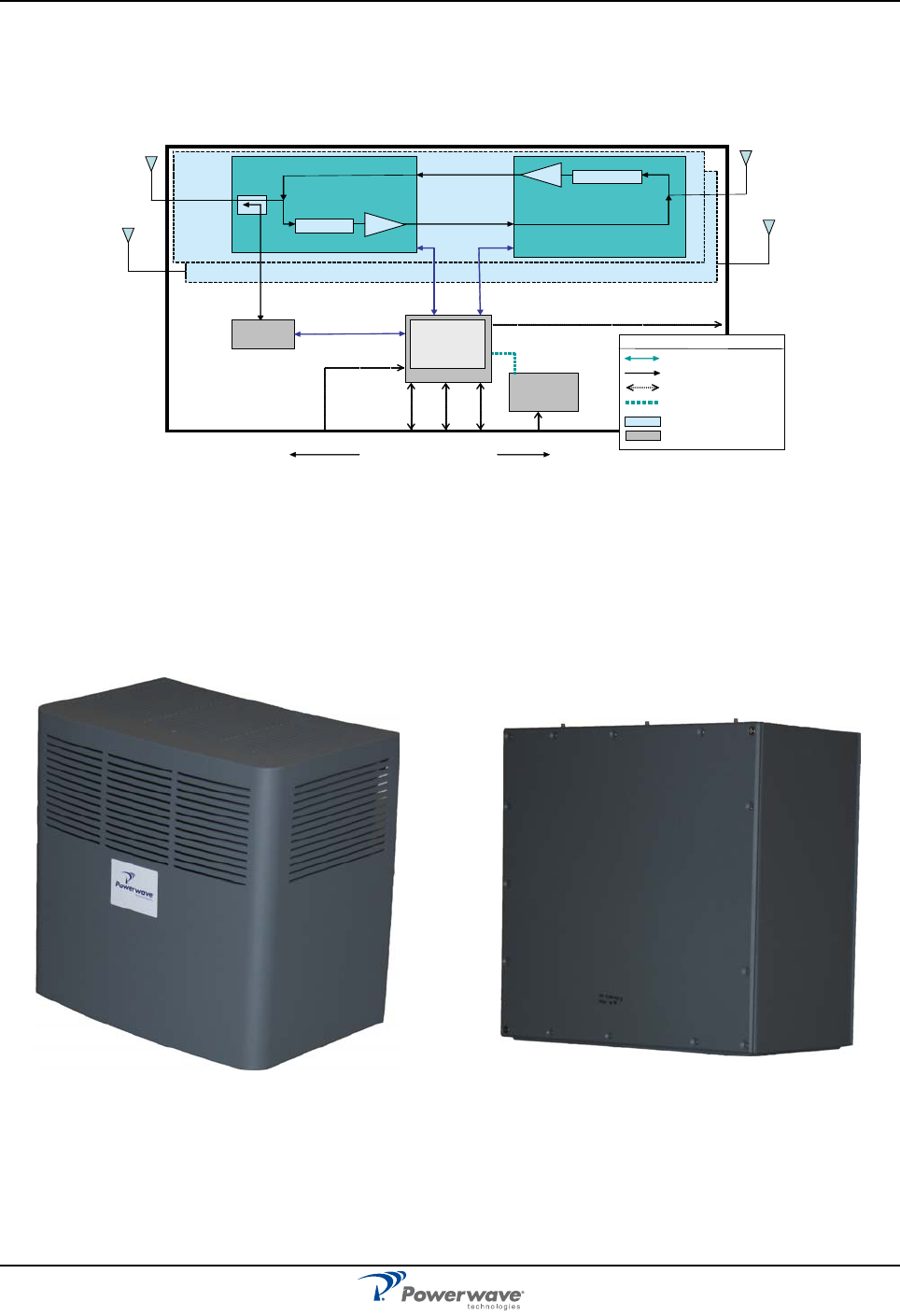
Figure 1-1 shows a block diagram of the Nexus RT.
Figure 1-1 Nexus RT Block Diagram
Chassis Design
The Nexus RT is housed in a cast aluminum, waterproof chassis, with a detachable sun shield approved for
outdoor use. Using an appropriate mounting bracket, the Nexus RT can be mounted on a wall.
Figure 1-2 illustrates the Nexus RT repeater with and without the sunshield attached.
Figure 1-2 Nexus RT Repeater Enclosure
Nexus RTi
Top Level Block Diagram
Legend
USB Comms
RF Path
External Interfaces
I2C Comms
RF Band Block
Not Per-Band
Wireless
Modem
Network
Element
Processor
Power
Supply
Band 1
Donor
Side
Service
Side
ENCLOSURE
Band 2
USB
RCM
I2C
USB/RS-232
4 Alarm Inputs
RCM
Donor
Duplexer
Assy
Service
Duplexer
Assy
DPA
SPA
USB
I/OBoard
PowerRS-232WANLocal
ENet
4 LED Indicators on Bulkhead
Circular DIN Connectors
Type N
RF
Type N
RF
Type N
Type N
RF
RF
Sunshield attached Sunshield removed
Nexus RT Overview
044-05311 Rev A 1-3
Main Chassis
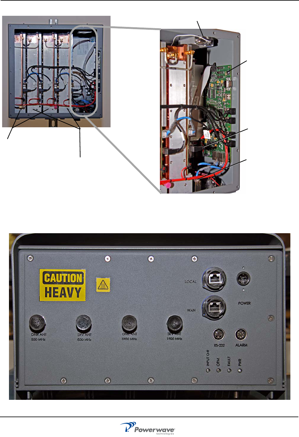
Figure 1-3 Nexus RT Dual Slice Configuration
Nexus RT Connections
Figure 1-4 Nexus RT Connections
Wireless Modem
Power Supply
Network
Element Processor
Board
Input/Output Board
Donor Duplexer Assemblies
(DDA)
Service Duplexer Assemblies
(SDA)

Overview Nexus RT
1-4 044-05311 Rev A
This page intentionally left blank
044-05311 Rev A 2-1
Chapter 2
Indicators and Connectors
Introduction
This chapter contains descriptions of the controls, indicators, and connectors for the Nexus RT.
Indicators
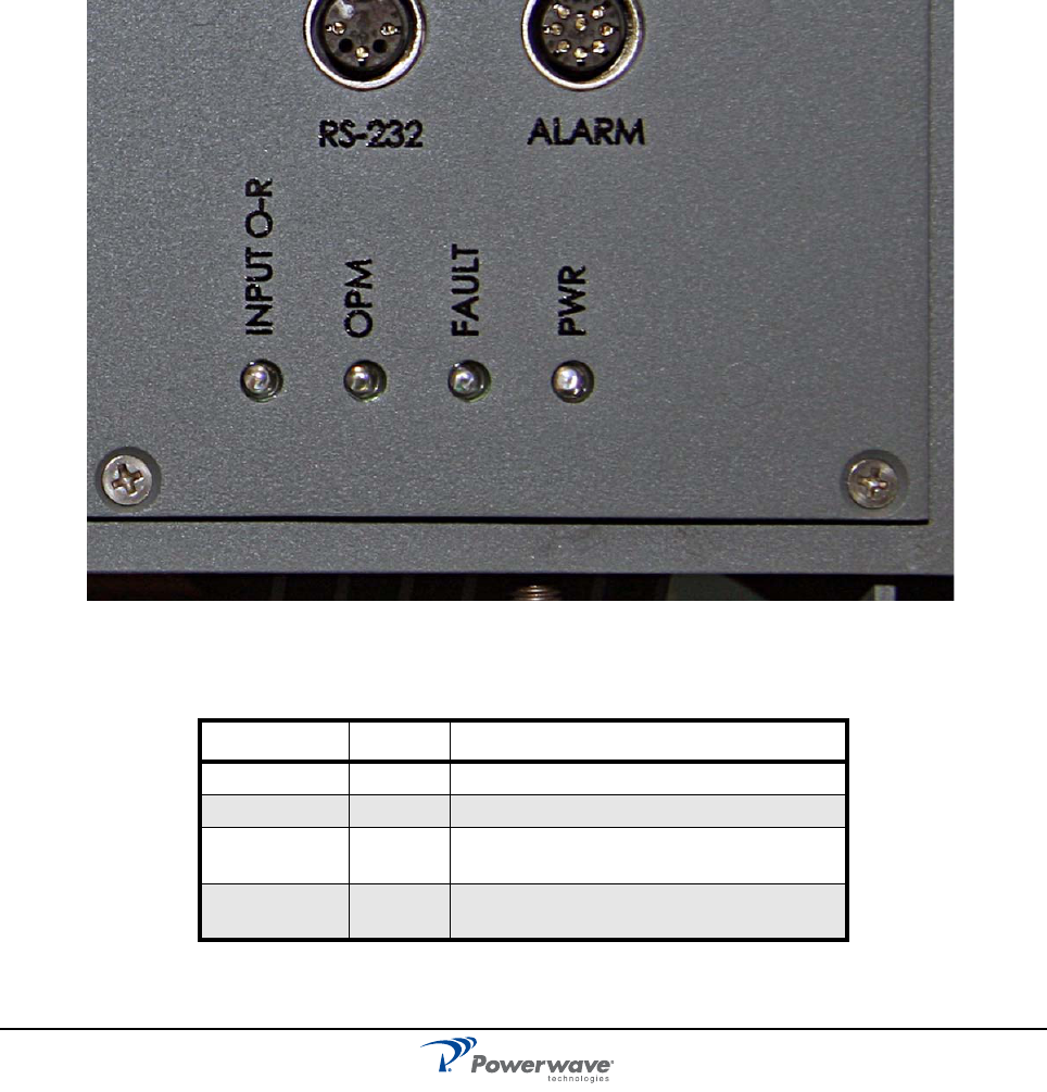
Four LEDs, shown in Figure 2-1 and described in Table 2-1, are located on the bottom of the Nexus RT to
provide easy identification of system status.
Figure 2-1 External Indicators
Table 2-1 External Indicators
LED Color Indicates
INPUT O-R Amber Input Over-Range
OPM Amber Oscillation Protection Mode
FAULT Red Flashing–System error
Steady–Critical alarm
PWR Green Ready for operation
(Lights up 15 seconds after power applied)
Connectors Nexus RT
2-2 044-05311 Rev A
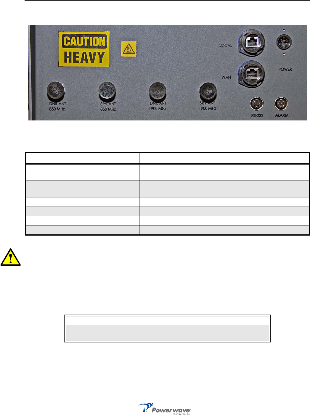
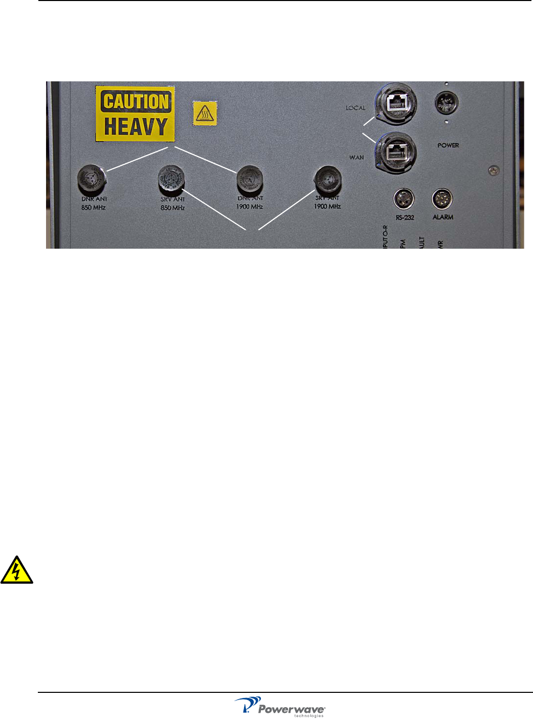
Connectors
Figure 2-2 and Table 2-2 describe the connectors available on the Nexus RT repeater.
Figure 2-2 Nexus RT Connectors
CAUTION: All connectors are located on the bottom face of the repeater.To avoid damaging the connec-
tors, do not set the set the repeater down on the connector side.
Software and Hardware Compatibility
There are different versions of Contol Unit (CU) Printed Circuit Board Assembly (PCBA) software which can
be combined with PCBAs of various revisions. These have unique part numbers and revision information.
Table 2-3 lists the software currently available in combination with CU PCBA revisions.
Table 2-3 Hardware / Software Compatibility
This information is accurate as of 06/31/2007. As new versions of hardware and software are released without
prior notice, contact your Powerwave sales representative for information on the latest revision.
For detailed information, refer to the release notes for the CU software to be downloaded (normally found in
the readme.txt file provided with the program files).
Table 2-2 Nexus RT Connectors
Connector Type Purpose
DNR ANT 850 MHz
SRV ANT 850 MHz
Type N Female Connectors for receive/transmit signals in 850 MHz
DNR ANT 1900 MHz
SRV ANT 1900 MHz
Type N Female Connectors for receive/transmit signals in 1900 MHz
POWER Circular DIN Main power connector
LOCAL and WAN RJ-45 Connectors for repeater control and status
RS-232 Circular DIN Factory use only
ALARM Circular DIN Connector for alarm signals external to the repeater
CU PCBA part number CU Software part number
500-13817-001 (previously K103/3) D631-18072-001
D631-18072-003

044-05311 Rev A 3-1
Chapter 3
Installation
Introduction
This chapter contains unpacking and inspection, and mounting installation instructions for powering up the
Nexus RT.
Site Survey
Powerwave recommends that a site survey be performed prior to ordering or installing equipment. Performing
a detailed site survey reduces or eliminates installation and turn-up delays. Pay particular attention to power
plant capacity, cooling needs, floor space, and RF/DC cabling/breaker requirements. Cabinet dimensions and
weights are listed in Chapter 5.
Unpacking and Inspection
This equipment has been operated, tested, and calibrated at the factory. Carefully open containers to remove
equipment. Retain all packing material that can be reassembled in the event unit must be returned to the
factory. Perform the following steps:
❑ Visually inspect equipment for damage that may have occurred during shipment. If possible, in the
presence of the delivery person.
❑ Check for evidence of water damage, bent or warped chassis, loose screws or nuts, or extraneous
packing material in connectors.
If any equipment is damaged, file a claim with the carrier once the extent of any damage is assessed.
If any equipment must be returned to factory, please contact the factory for a Return Material Authorization
(RMA). See Chapter 4.
Nexus RT Location
The Nexus RT is designed with a weatherproof outdoor cabinet. The unit can also be installed indoors. A
preferable site for the Nexus RT is a location free of obstructions, easily accessible, and that allows for proper
air-flow and ventilation.
A Sunshield is available for situations where the Nexus RT is installed outdoors and can be exposed to direct
sunlight. It is essential that air circulates around the Nexus RT with no obstacles. The operating temperature
must not exceed 55°C (131°F).
Never open a Nexus RT when rain, snow, hail, high humidity or high winds are present unless some kind of
temporary shelter can be erected.
Mounting Nexus RT
3-2 044-05311 Rev A
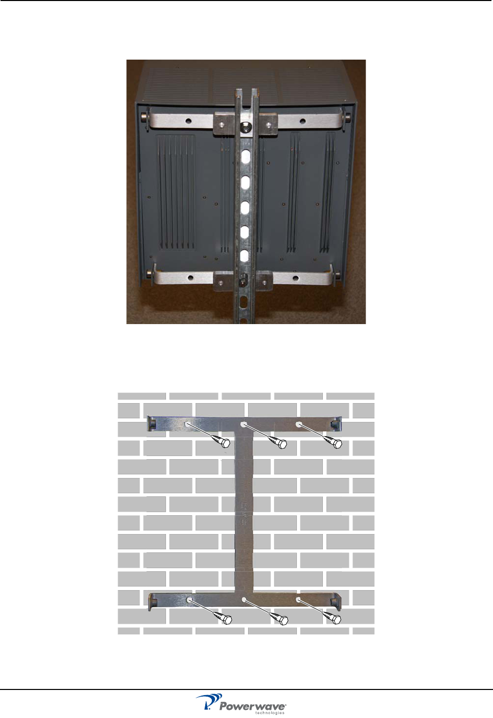
Mounting
Use the mounting bracket provided (as shown in Figure 3-1) to mount the Nexus RT on a wall.
Figure 3-1 Mounting Bracket
Figure 3-2 illustrates the installation of the mounting bracket on a wall using six fixing screws.
Figure 3-2 Mounting Bracket Installation on Wall
Nexus RT Mounting
044-05311 Rev A 3-3
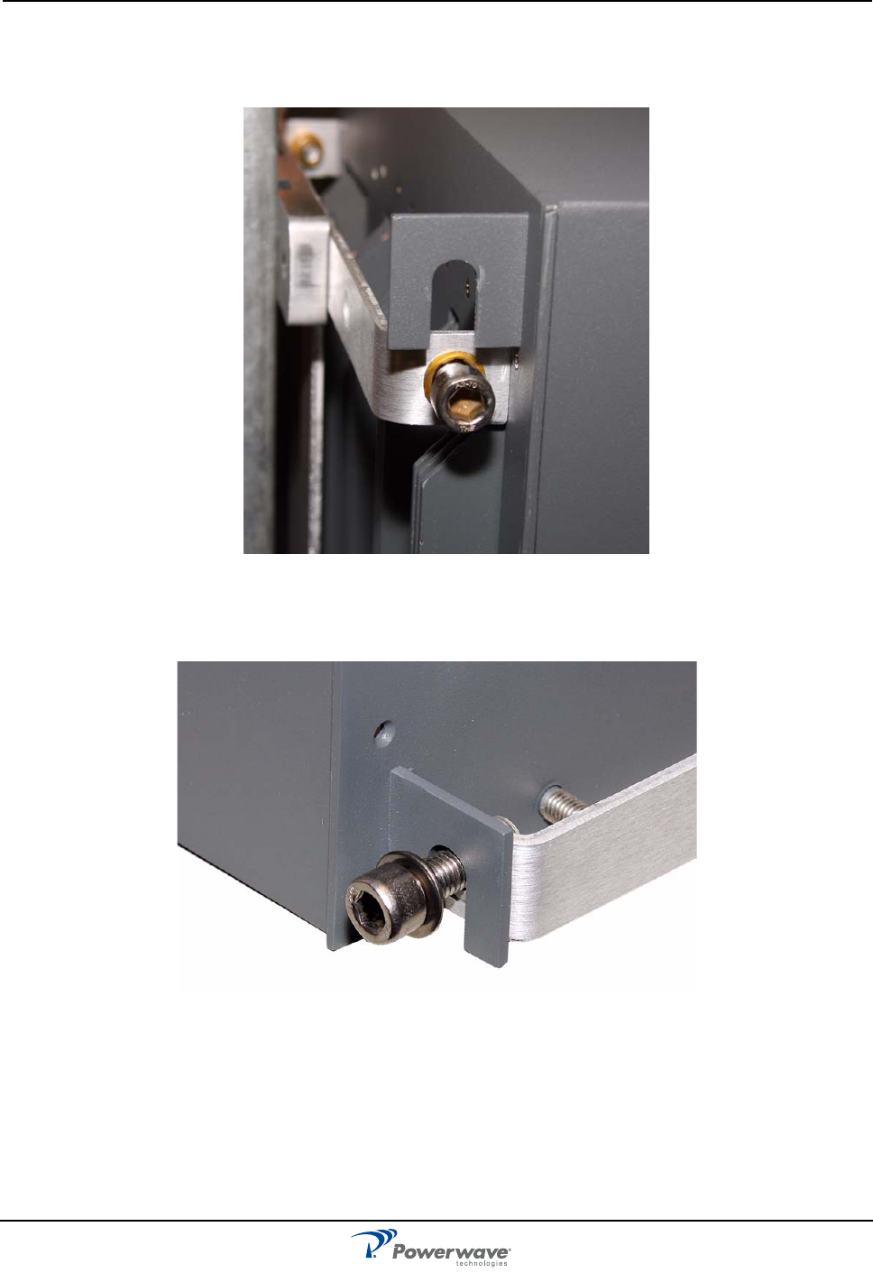
Mounting the Nexus RT on the Bracket
1. After installing the mounting bracket, insert the mounting screws into the bracket, then hook the upper
supports on the Nexus RT over the mounting screws, as illustrated in Figure 3-3.
Figure 3-3 Attaching the Nexus RT upper supports
2. Align the lower supports with the mounting holes on the bracket, then insert the lower mounting screws,
as shown in Figure 3-4
Figure 3-4 Attaching the Nexus RT lower supports
3. Tighten the screws using a 6mm hex socket wrench to secure the Nexus RT tn place.
Locking cylinders, used to prevent unauthorized removal of the repeater, can be inserted and locked with a
key after the lower screws have been tightened.
4. Verify that the donor antenna (directed toward the Base Tranceiver Staton antenna) and the service
antenna (directed toward the area to be covered by the Nexus RT) are mounted and installed properly.
Connections Nexus RT
3-4 044-05311 Rev A
Connections
This section describes general examples of how to connect the input and output ports on the Nexus RT.
Figure 3-5illustrates the connections for the Nexus RT.
.
Figure 3-5 Nexus RT Cable Connections
1— RF Input/Output – Donor Side. The reverse transmit and forward receive signals are duplexed onto
one RF port. There is one donor side connector for each band.
2—RF Input/Output – Service Side. The forward transmit and reverse receive signals are also duplexed
onto one RF port. There is one service side connector for each band.
3—Power Input – Prime power input for the repeater.
4—IP Connections – Ethernet connections for control and status of the Nexus RT. One for local and one
for wide area network (WAN).
5—Serial Port. An RS-232 interface for factory use only.
6—External Alarm Input. This is a connection port for alarm input signals external to the Nexus repeater.
The Nexus RT also has a wireless modem interface for communicating control and status information with the
network management system. The repeater supports a USB interface between the Network Element
Procesor (NEP) and modem.
Main Power and Grounding
Local regulations need to be followed for the main power connection. Nexus RTs are approved in accordance
with EN and UL/cUL regulations. This is, however, only valid if a classified power cord is used. For the
Nexus RT to meet these regulations you must select one of the following classified and approved cord types:
❑ EN – H 05 W5 - F HMR
❑ UL – AWM Style 2587
❑ CSA– AWM 1 A/B 11 A/B
For outdoor use, the power cord should meet at least IP65 encapsulation requirements. Do not turn the main
power on until you are ready to commission the Nexus RT
WARNING: For Nexus RTs supplied from the main power source, the main outlet must be
grounded.
Connecting RF Cables
RF cable connections should be verified both internally and externally before powering up the equipment.
This section describes the general internal connections of the Nexus RT. Verify these connections with the
as-built drawings and documents for your specific system configuration.
1. Connect the service and donor antenna coaxial cables to the appropriate terminals on the cabinet.
2. Plug the main power cord into the terminal labeled POWER.
1
2
3
4
56
Nexus RT Connections
044-05311 Rev A 3-5
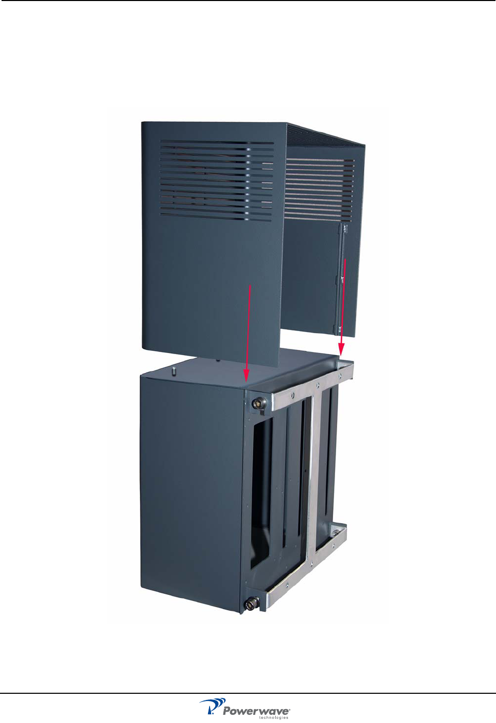
Attaching the Sunshield
The Nexus RT is housed in a cast aluminum, waterproof chassis, with a detachable sunshield approved for
outdoor use.
To attach the sunshield, align the grooves on the inside of the sunshield with the tabs on the Nexus RT
housing and slide the sunshield down until it stops, as shown in Figure 3-6.
Figure 3-6 Attaching the Sunshield
Commissioning Nexus RT
3-6 044-05311 Rev A
Commissioning
Before proceeding, carefully read the Safety section and check all connections made during the installation.
To fulfill the IP65 weather protective requirements, ensure cable strain relief bushings are properly tightened.
Also, ensure the gaskets at cable inlets and on the cabinet are properly fitted and not damaged.
Initial Startup
To complete the initial start-up of the Nexus RT, follow the steps listed below.
1. Turn on the main power. All LEDs will light up.
2. After about five seconds, check the PWR LED. If it shows green and steady, the Nexus RT is functioning
correctly.
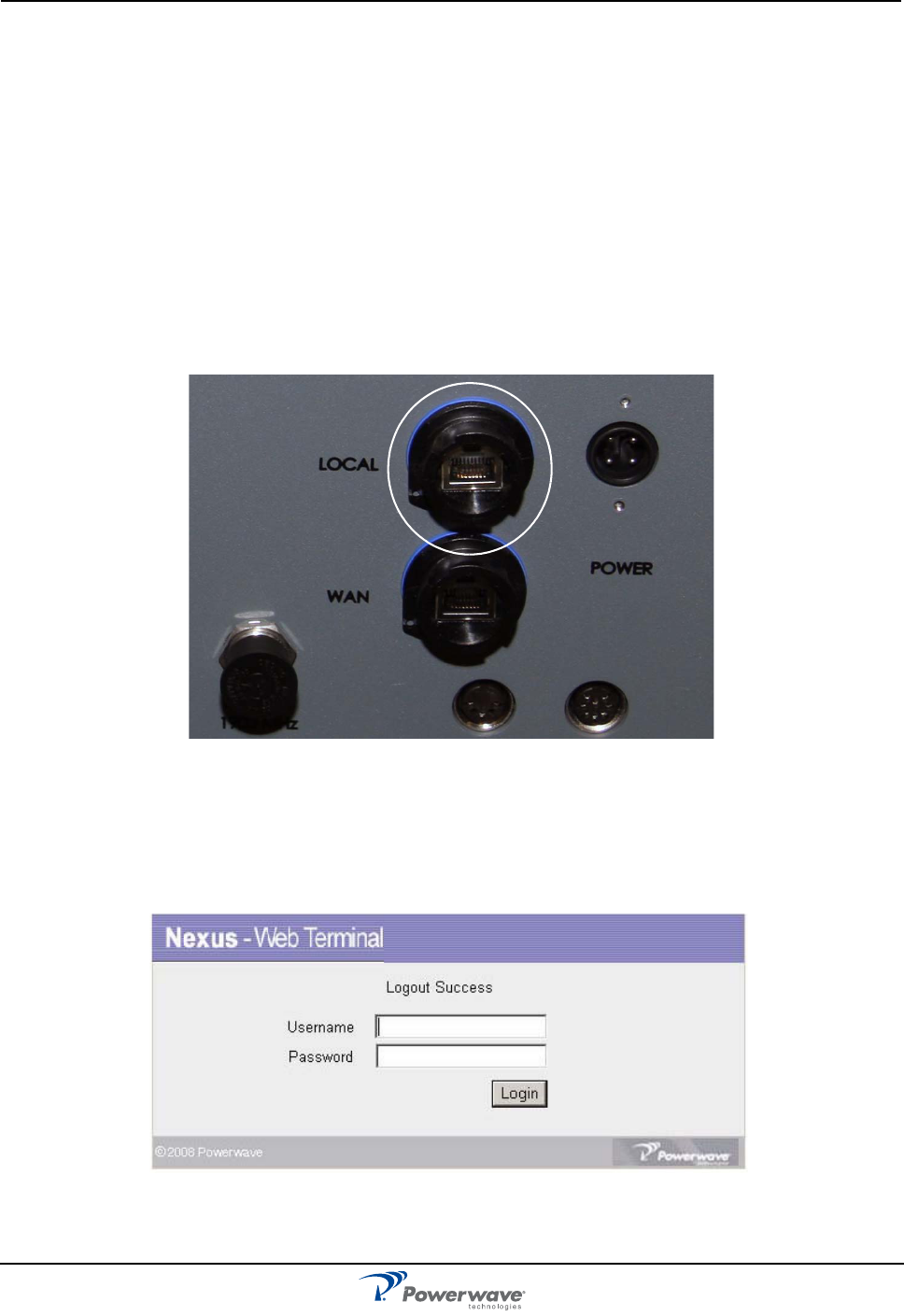
Configure the Nexus RT
The Nexus RT can be configured locally with the built-in web terminal interface. Connect a standard Ethernet
cable from the RJ45 socket on a PC to the LOCAL connector located on the bottom of the cabinet as shown
in Figure 3-7.
Figure 3-7 Connection for Local Access
Log in
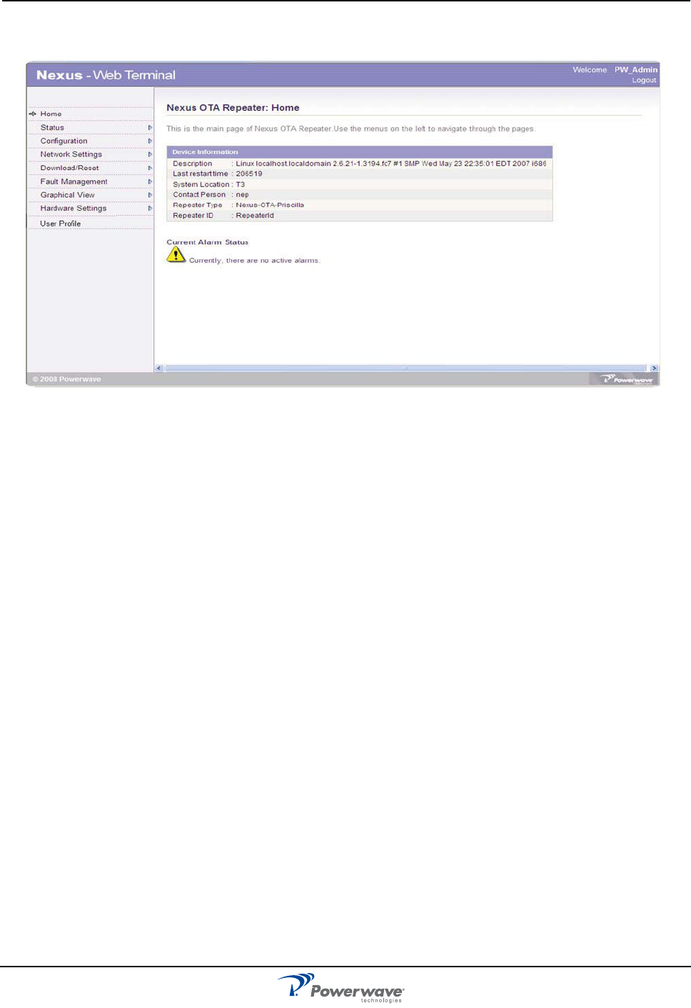
Follow these steps to access the Nexus RT interface pages.
1. Open a web browser on your PC.
2. Enter the IP address of the LOCAL port on the Nexus RT (192.168.47.10) in the URL address field and
press Return. The login dialog box, as shown in Figure 3-8, displays.
Figure 3-8 Nexus Web Terminal Login Screen

Commissioning Nexus RT
3-8 044-05311 Rev A
This page intentionally left blank
044-05311 Rev A 4-1
Chapter 4
Maintenance
Introduction
This chapter contains periodic maintenance and procedures to return the Nexus RT for service.
Periodic Maintenance
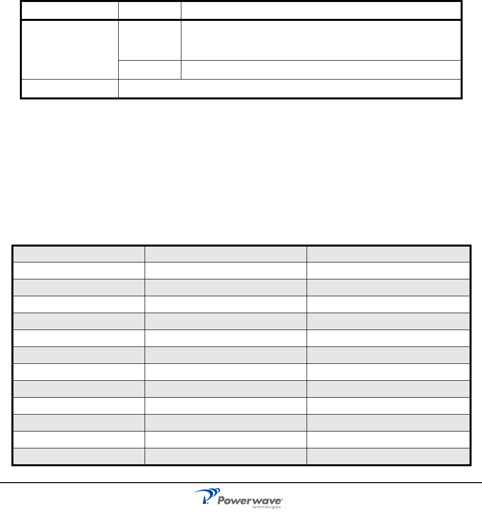
Refer to Table 4-1 for Periodic maintenance requirementsand the intervals at which to perform the tasks.
Troubleshooting
The sections that follow contain a list of problems that could occur and a few suggested actions that might
correct each problem. If the suggested corrective action does not eliminate the problem, please contact your
Powerwave field representative or customer service for further instruction.
Alarm Faults
The Nexus RT Web Interface pages provide an overview of the repeater’s status and alarm situation asl isted
inTable 4-2 Nexus RT Alarms . Please refer to the the Nexus RT Configuration Manual (044-05341) for more
information.
Table 4-1 Recommended Periodic Maintenance
Task Interval Action
Inspection of cables
and connectors
12 months Inspect power and RF cables for signs of damage or wear (frayed
insulation, cracks, punctures, etc.) Check connections to be sure
they are tight
Optional Perform cable sweeps
Clean equipment Clean as required depending on operating environment
Table 4-2 Nexus RT Alarms
Power Supply Voltage Modem SIM Card Door Open High Temperature
Flash Disk Failure NEP Improper ShutDown OS Rebooted
Modem Disconnected External Contact 1 External Contact 2
External Contact 3 External Contact 4 Modem Signal Strength Out of Range
Invalid Kernel Version Invalid UBoot Version High Return Loss
Heart Beat Power Amplifier Over Power Communication Failure
Slice Module Missing Echo Canceller Not Balanced Reference PLL Unlocked
Master Synthesizer Unlocked OBS LO Synthesizer Unlocked TX LO Synthesizer Unlocked
RX LO Synthesizer Unlocked RX ADC PLL Unlocked FPGA PLL Unlocked
Echo Canceller Error RX ADC Overflow Reported OBS ADC Overflow Reported
DDC Overflow Reported DUC Overflow Reported PA High Temperature
High VSWR Level LNA Fault High Output Power
Invalid FPGA Version Invalid FX2 Version Invalid DSP Version

Field Replaceable Units Nexus RT
4-2 044-05311 Rev A
Field Replaceable Units
There are no field replaceable components in the Nexus RT. If any components fail, plese contact Powerwave
for assistance.
Return For Service Procedures
When returning products to Powerwave, the following procedures will ensure optimum response.
Obtaining an RMA
A Return Material Authorization (RMA) number must be obtained prior to returning equipment to the factory
for service. Pease contact our Repair Department at +1-714-466-1000 to obtain this number, or FAX your
request to +1-714-466-5800. Failure to obtain this RMA number may result in delays in receiving repair
service.
Repackaging for Shipment
To ensure safe shipment of the unit, it is recommended that the original package designed for shipping the
unit be reused. If it is not available, contact Powerwave’s Customer Service Department at 1-800-797-9283,
+1-714-466-100 or by e-mail at support@pwav.com for packing material.

044-05311 Rev A 5-1
Chapter 5
Specifications
Introduction
This chapter provides specifications for the Nexus RT.
Table 5-1: Nexus RT Specifications
Electrical
Frequency band UL 824 to 849 MHz (Cellular)
1850 to 1910 MHz (PCS)
Frequency band DL 869 to 894 MHz (Cellular)
1930 to 1990 MHz (PCS)
Gain adjustment range (in 1 dB steps) 55 - 85 dB
Gain
Uplink
/Downlink
-10 to +30 dBm
+20 to +45 dBm
Instantaneous bandwidth 25 MHz
Return Loss <-15 dB
Downlink, Spurious and Emissions level -160 dBm/Hz
Output Power - Downlink +25 dB Composite
Noise figure 5 dB
Power supply voltage 110 - 120 VAC
Maximum Current Draw (Single Band) 70 w
Power consumption < 200 W typical
Impedance
IOutput 50 Ω
Mechanical
Dimensions (W x H x D in inches) 393.7 mm (15.5 in.) x 381 mm (15 in.) x 266.7 mm (10.5 in)
Weight 20 Kg (44 lbs) Single Band Configuration
27 Kg (60 lbs) Dual Band Configuration
Service Antenna port connector N Type Female
Donor Optical port connector N Type Female
Environmental
Operating Temperature Range -30 °C to +50 °C (-22°F to +122°F)
Altitude -30.48 m to 1828.8 m (-100 ft. to 6000 ft.)
Casing class IP50

Worldwide Corporate Headquarters
1801 East St. Andrew Place
Santa Ana, CA 92705 USA
+1 714 466 1000
+1 714 466 5800 FAX
www.powerwave.com
Main European Office
Knarrarnasgatan 7 8tr.
164 40 Kista, Sweden
+46 8-540-822-00
+46 8-540-824-91 FAX
Main Asia-Pacific Office
23 F Tai Yau Building
181 Johnston Road
Wanchai, Hong Kong
+852 2512 6123
+852 2575 4860 FAX
Powerwave Technologies, Inc. All rights reserved. Powerwave, Powerwave Technologies, and the Powerwave logo are registered trade-
marks of Powerwave Technologies, Inc.