Powerwave Technologies 922801 Tower Top Power Apmilfier/Booster User Manual manual
Powerwave Technologies Inc. Tower Top Power Apmilfier/Booster manual
manual

ALLGON SYSTEM AB - Proprietary
Technical Specification for PCS Tower Top Power Amplifier [Allgon 9256]
Preliminary - Subjected to change without notice Rev.pA0
File: 93651 Page 1 (19) 29 Mar 00
TOWER TOP POWER AMPLIFIER
PCS 1900MHZ / 20W
STANDALONE
TECHNICAL SPECIFICATION

ALLGON SYSTEM AB - Proprietary
Technical Specification for PCS Tower Top Power Amplifier [Allgon 9256]
Preliminary - Subjected to change without notice Rev.pA0
File: 93651 Page 2 (19) 29 Mar 00
1 INTRODUCTION..........................................................................................................................................3
1.1 PURPOSE ...............................................................................................................................................3
1.2 SCOPE...................................................................................................................................................3
1.3 REVISION HISTORY....................................................................................................................................3
1.4 RELATED DOCUMENTS .............................................................................................................................3
1.5 ABBREVIATIONS .......................................................................................................................................3
1.6 DEFINITIONS ............................................................................................................................................3
2 PRODUCT VARIANT DEFINITION ................................................................................................................5
2.1 DEFINITION OF THE AVAILABLE VARIANTS.......................................................................................................5
2.2 OPTIONAL FUNCTION SELECTION GUIDE ........................................................................................................5
3 SYSTEM OVERVIEW...................................................................................................................................6
3.1 GENERAL ...............................................................................................................................................6
3.2 PRINCIPLE OF OPERATION.........................................................................................................................7
4 ELECTRICAL SPECIFICATION...................................................................................................................10
4.1 ABSOLUTE MAXIMUM RATINGS..................................................................................................................10
4.2 GENERAL PARAMETERS.......................................................................................................................... 10
4.3 TRANSMIT PATH PARAMETERS.................................................................................................................. 11
4.4 RECEIVE PATH PARAMETERS...................................................................................................................13
4.5 FILTER PARAMETERS.............................................................................................................................. 14
4.6 POWER SUPPLY PARAMETERS ................................................................................................................. 14
5 MECHANICAL SPECIFICATION..................................................................................................................15
5.1 PHYSICAL PARAMETERS..........................................................................................................................15
5.2 INTERFACES .........................................................................................................................................15
5.3 MOUNTING ............................................................................................................................................16
6 ENVIRONMENTAL SPECIFICATION...........................................................................................................17
6.1 OPERATING CONDITIONS.......................................................................................................................... 17
6.2 STORAGE AND TRANSPORTATION ..............................................................................................................17
6.3 ELECTROMAGNETIC COMPATIBILITY (EMC) ................................................................................................. 18
6.4 LIGHTNING PROTECTION........................................................................................................................... 18
7 RELIABILTIY SPECIFICATION ................................................................................................................... 18
7.1 OPERATING LIFE .................................................................................................................................... 18
7.2 THEORETICAL MTBF..............................................................................................................................18
7.3 FIELD PROVEN MTBF ............................................................................................................................19
8 SAFETY SPECIFICATION ..........................................................................................................................19
8.1 TOXIC MATERIALS.................................................................................................................................. 19
8.2 SAFETY CLASSIFICATIONS........................................................................................................................19
9 SERVICE AND MAINTENANCE ..................................................................................................................19
9.1 SERVICE ..............................................................................................................................................19
9.2 MAINTENANCE.......................................................................................................................................19

ALLGON SYSTEM AB - Proprietary
Technical Specification for PCS Tower Top Power Amplifier [Allgon 9256]
Preliminary - Subjected to change without notice Rev.pA0
File: 93651 Page 3 (19) 29 Mar 00
1 INTRODUCTION
1.1 PURPOSE
This document describes the Technical specification for the Allgon Tower Top Power Amplifier for the PCS
1900 cellular band. The product number specified in the header has different variants available. These
variants have different bandwidths, gain and options. A definition of the different available variants and a
selection guide can be found in chapter 2.
1.2 SCOPE
The document details the total Technical performance of the TTPA, with respect to Electrical,
Mechanical, Environmental, Safety and Reliability related parameters. Only the mast head mounted unit
is described in this document. Other related products, such as APDU and Current Injectors, are
described in other documents.
1.3 REVISION HISTORY
Rev. pA0 Draft 990518 M.Österberg
Rev. Second draft
1.4 RELATED DOCUMENTS
TIA, PS No 3389
Technical Specification for APDU 9209
Technical Specification for CI 9219
1.5 ABBREVIATIONS
TTPA Tower Top Power Amplifier
PDU Power Distribution Unit
APDU Alarm And Power Distribution Unit
CI Current Injector
PCN Personal Cellular Network
AGC Automatic Gain Control
ANT Antenna
BTS Base Transceiver Station
LED Light Emitting Diode
MTBF Mean Time Between Failures
MTTR Mean Time To Replace
PA Power Amplifier
1.6 DEFINITIONS
! Normal operating conditions:
The full operating performance specified in this document is guaranteed under conditions stated below:
Ambient temperature: Acc. to chapter 7 , after 30 min normal operation.
Environment: Acc. to chapter 7 , after 30 min normal operation.
DC power supply: Acc. to chapter 4.
Return loss: > 18dB on all RF ports.

ALLGON SYSTEM AB - Proprietary
Technical Specification for PCS Tower Top Power Amplifier [Allgon 9256]
Preliminary - Subjected to change without notice Rev.pA0
File: 93651 Page 4 (19) 29 Mar 00
Mounting: Acc. to chapter 5.3
The parameters specified are guaranteed over the warranty time.
! Typical parameters:
All typical parameters are considered to be measured at an ambient temperature of 20 °C, and air
pressure of 1013 mbar, after 30 min warm up, unless otherwise stated. The TTPA is designed for an
operating life exceeding 10 years.
ALLGON SYSTEM AB - Proprietary
Technical Specification for PCS Tower Top Power Amplifier [Allgon 9256]
Preliminary - Subjected to change without notice Rev.pA0
File: 93651 Page 5 (19) 29 Mar 00
2 PRODUCT VARIANT DEFINITION
The TTPA are available with different frequency bands, together covering all PCS bands. A number of
optional functions (listed in 2.2) are available depending on configuration. The existing, and preferred
product configurations, are listen in 2.1.
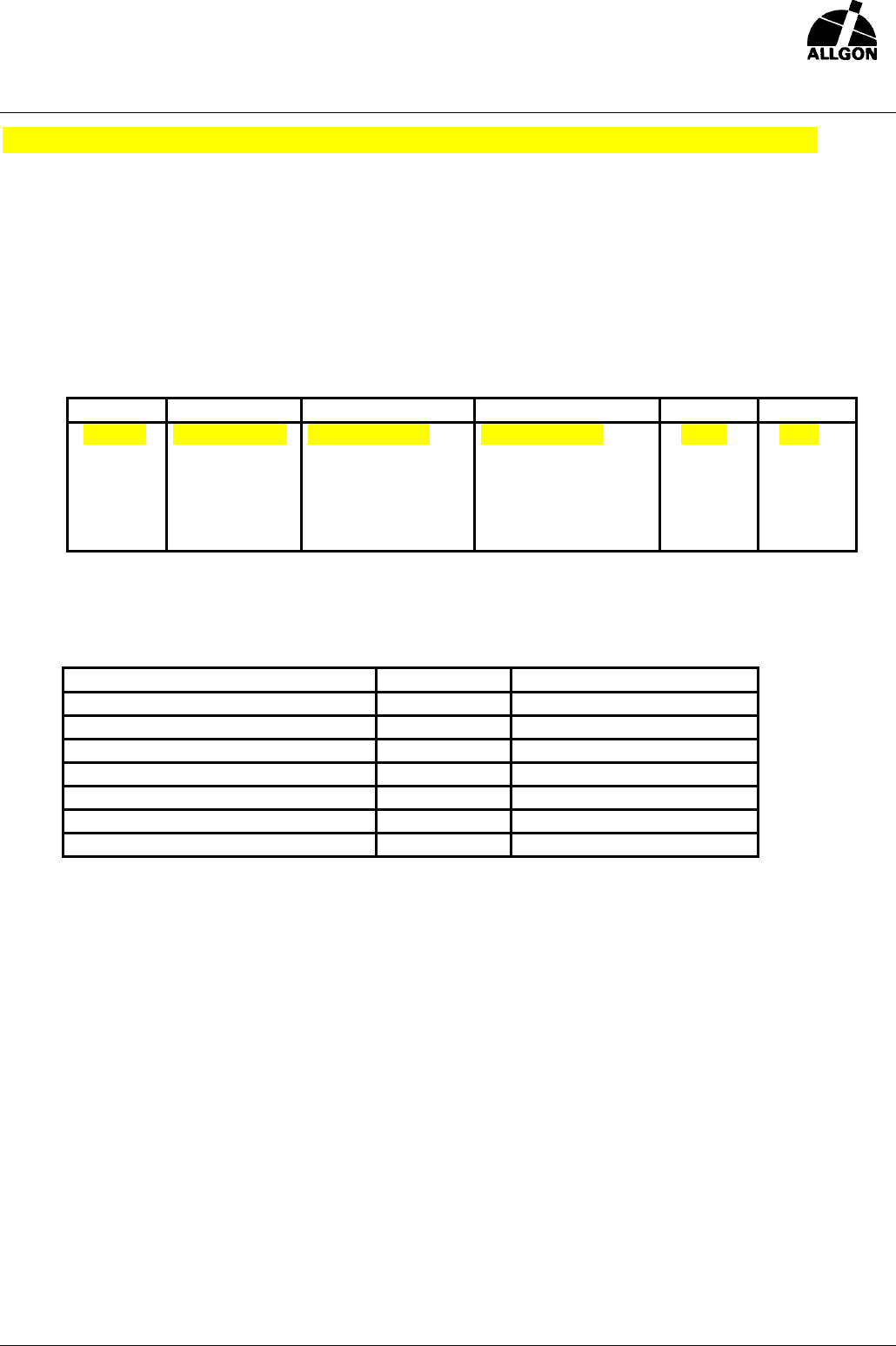
2.1 DEFINITION OF THE AVAILABLE VARIANTS
Variant Band / width RX Freq.band TX Freq.band TX Gain Options
9228.01 A+D / 20 MHz 1850-1870 MHz 1930-1950 MHz 7 dB 1,4,6
9228.02 B+E / 20 MHz 1870-1890 MHz 1950-1970 MHz 7 dB 1,4,6
9228.03* C+F / 20 MHz 1890-1910 MHz 1970-1990 MHz 7 dB 1,4,6
*Future Product
2.2 OPTIONAL FUNCTION SELECTION GUIDE
Option
See Section
Included in variant #
1. Fixed RX Gain 13dB 3.6.2 01,02,03
2. Separate DC connector 4.2.4
3. Separate Alarm connector 4.2.5 01,02,03
4. Redundant DC/DC 3.8.4
5. Antenna supervision 3.4.4
6. RX bypass 3.6.6
7. TX bypass 3.5.11 01,02,03
ALLGON SYSTEM AB - Proprietary
Technical Specification for PCS Tower Top Power Amplifier [Allgon 9256]
Preliminary - Subjected to change without notice Rev.pA0
File: 93651 Page 6 (19) 29 Mar 00
3 SYSTEM OVERVIEW
3.1 GENERAL
The PCS Tower Top Power Amplifier (TTPA) is intended for use at sites where it is necessary to improve
the coverage area. The TTPA boosts both the receive-path signal and the transmit power from one TRx in
order to preserve site link balance. TX and RX signal paths are separated by means of duplexers. The TX
Power Amplifier (PA), as well as the RX Low Noise Amplifier (LNA), utilizes balanced architectures to add
redundancy.
The TTPA can also be used together with a micro or mini BTS to reach coverage equivalent with a far
more expensive Macro BTS installation.
The TTPA has a small and lightweight design, which enables it to be mounted in the antenna tower, near
the antenna. This means that less costly feeders can be used since the attenuation becomes of less
concern when the PA and the LNA is situated near the antenna. DC power to the TTPA is supplied , via the
antenna feeder. The TTPA incorporates an advanced self-supervision system that automatically switches
the unit into bypass mode in the event of malfunction or power failure.
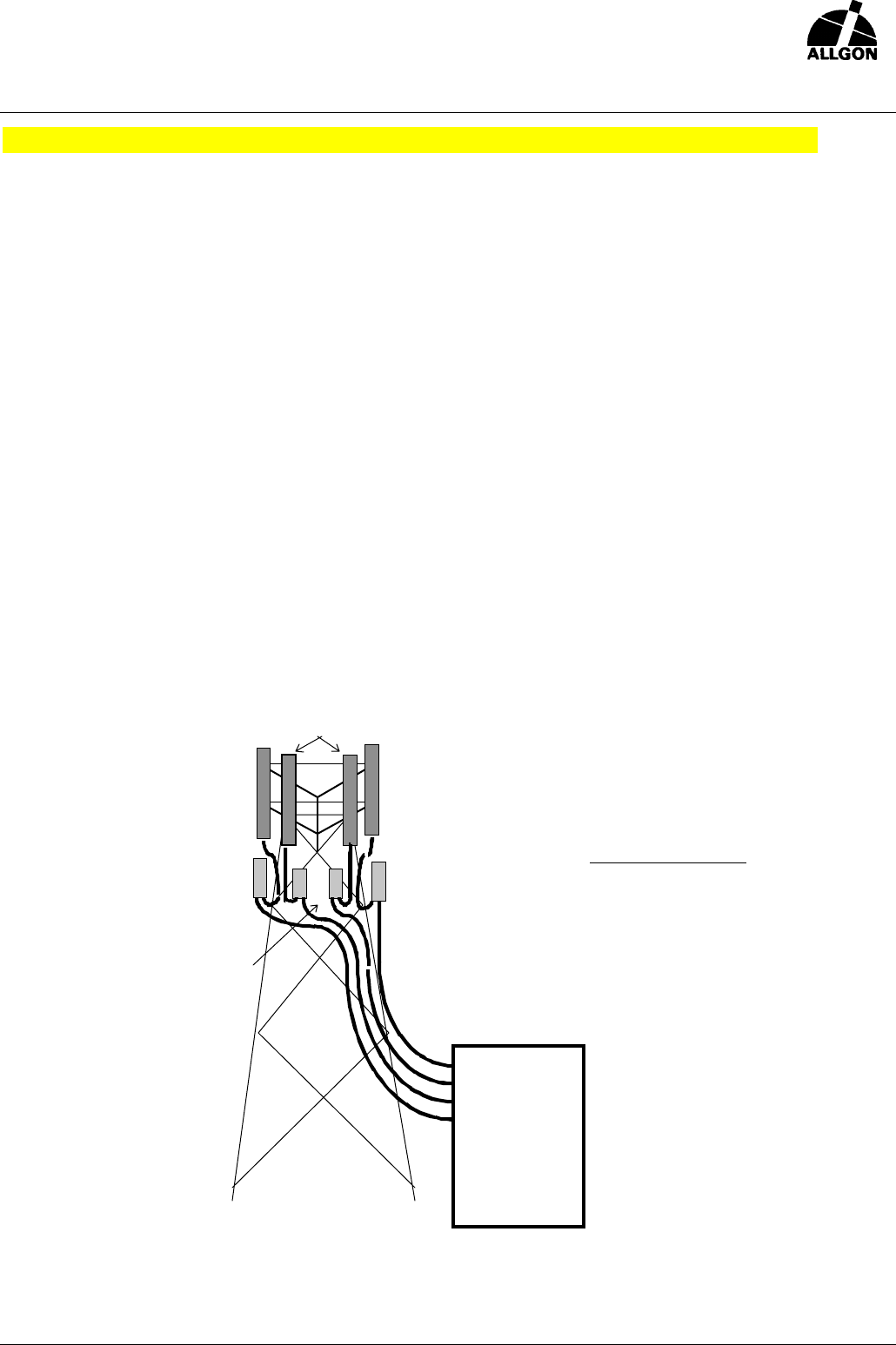
RX
RX/TX RX/TX
MHB
MHB
BTS
TTA
RX/TX
RX
RX
RX/TX
Figure 1. Typical site configuration with Tower Top Amplifiers.
KEY PARAMETERS
TX Gain: 7 dB
TX Power: +43 dBm (20W)
RX Gain: 13dB
ALLGON SYSTEM AB - Proprietary
Technical Specification for PCS Tower Top Power Amplifier [Allgon 9256]
Preliminary - Subjected to change without notice Rev.pA0
File: 93651 Page 7 (19) 29 Mar 00
3.2 PRINCIPLE OF OPERATION
3.2.1 General
The TTPA has the RX and the TX signal paths separated by means of duplex filter or isolators.
All circuitry for power supply and supervision are included inside the unit.
The TTPA has two ports designated BTS and ANT. The BTS port carries the signals to/from the
BTS rack (e.g. TX-in, RX-out, DC-power). The ANT port will be connected to the antenna. See
figure 2 Basic TTPA Block Diagram.
3.2.2 Transmit Path
The Transmit path incorporates a balanced power amplifier with high linearity. An Automatic
Gain Control circuit (AGC) keeps the gain at a constant level from input to ANT output. TX-path
Bypass is optional.
3.2.3 Receive Path
The Receive path consists of a balanced LNA with very low noise factor. The LNA has a gain
change capability in order to compensate for different feeder losses and optimize the link budget
on each site. RX bypass, which will cut in at power failure or LNA failure, is an optional function.
3.2.4 Power Supply
The Power Supply filters and regulates the input DC power to suit the amplifiers. DC power fed
into the unit on the BTS input connector through the feeder is standard. Separate DC connector
and redundant DC/DC is optional.
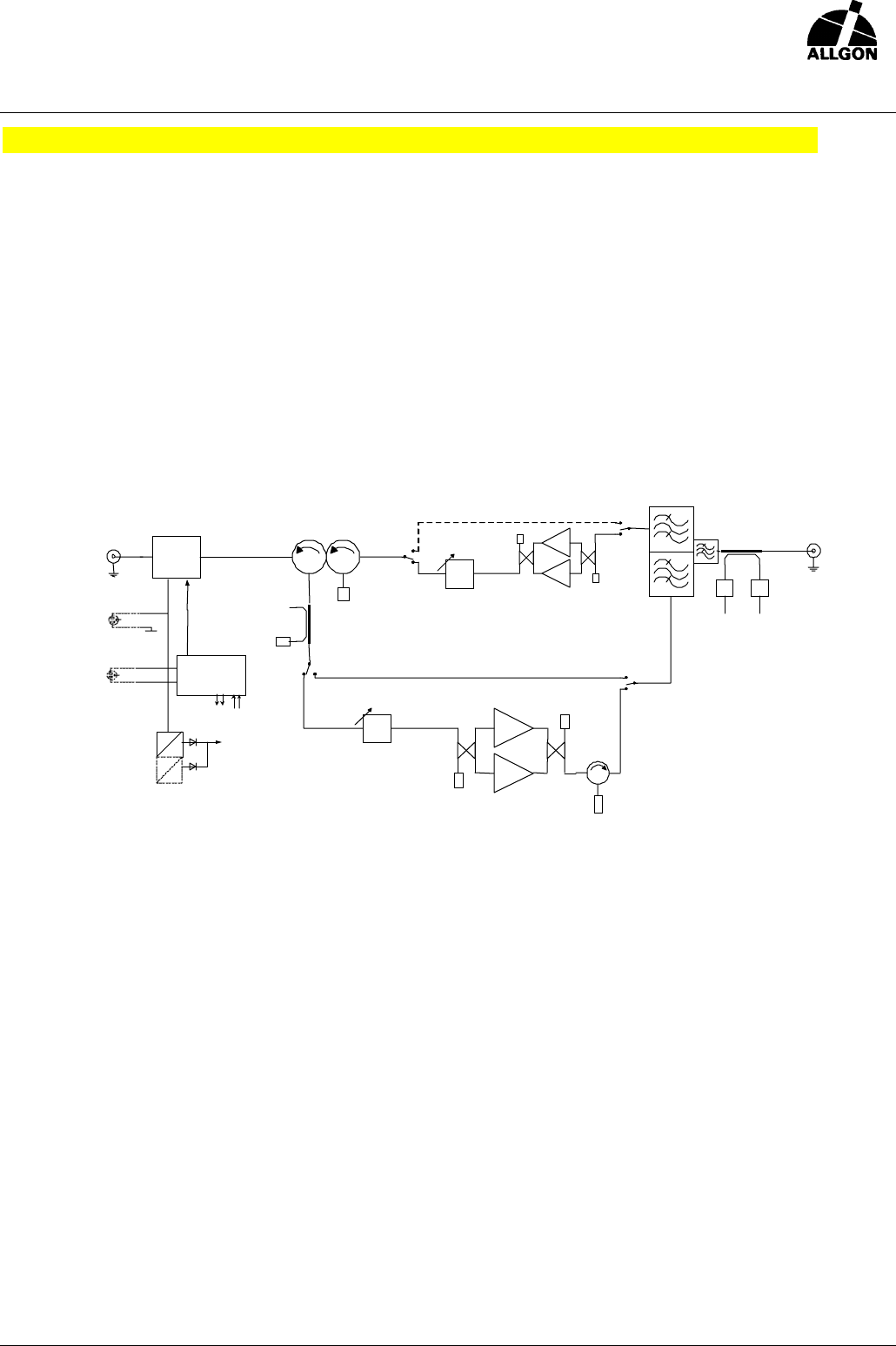
Figure 2. Block diagram of the Tower Top Power Amplifier.
EXT.DC
op ti on
CI
&
LP
dB
In pu t Pow er
BTS port
DC /D C 26V
26 V
dB dB
ANT port
Forward
Power
Re ve r se
Power
TX by p ass
dB
RX byp ass
SYSTEM
CONT ROLLE
EXT:ALARM
op ti on

ALLGON SYSTEM AB - Proprietary
Technical Specification for PCS Tower Top Power Amplifier [Allgon 9256]
Preliminary - Subjected to change without notice Rev.pA0
File: 93651 Page 8 (19) 29 Mar 00
3.2.5 Supervision
A number of parameters are constantly supervised.
TX Power Amplifier:
Output power, VSWR (when input power within specified limits), transistor currents, voltages,
temperature and power supply. VSWR supervision optional.
RX LNA:
Transistor currents and power supply.
Control unit:
The system controller at startup and at certain intervals makes a system self-test.
3.2.6 Alarming
The TTPA has an alarm connector with two independent relay contacts and an auxillary input.
The Relays are assigned to different alarms depending on whether it is a Major or Minor alarm
(Relay 1=Major, Relay 2=Minor).
This facilitates differentiation of minor alarms (not interrupting transmission) from major alarms
that indicates loss of transmission. All alarms can be gated to one by simply connecting the
contacts in parallel.
ALARM
Cause
Action in TTPA
Relay #
Overtemp Cooling flange above 80°C** RX_bypass****/TX Bypass**** 1
DC-Minor One DC/DC-converter failed none 2
DC-Major**** No DC power to TTPA * TX Bypass 1
TX-Minor One PA Transistor failed None 2
TX-Major PA Failure, No Gain PA shutdown & TX Bypass 1
RX-Minor One LNA Transistor failed None 2
RX-Major LNA Failure none 1
VSWR Alarm***
*
VSWR > 2.5:1*** none 2
OP-Alarm Output Power over Limit none 2
IP-Alarm Input Power over Limit none 2
RP-Alarm**** Reflected Power over Limit none 2
AGC-Alarm Gain control failed Gain accuracy reduced 2
AUX-Alarm**** Auxillary input shorted none1 2
TTA_Minor**** Diversity TTA minor failure none 2
TTA_Major**** Diversity TTA major failure none 2
SYS_Minor CPU System test failed none 2
SYS_Major CPU System test failed TX Bypass**** 1
* Either due to failure of both DC/DC converters, or no DC power applied to the unit.
** restart at +60°C
*** Default value. Software changeable level 2:1 to 5:1 is optional

ALLGON SYSTEM AB - Proprietary
Technical Specification for PCS Tower Top Power Amplifier [Allgon 9256]
Preliminary - Subjected to change without notice Rev.pA0
File: 93651 Page 9 (19) 29 Mar 00
**** Optional function, not supported in all variant.
ALLGON SYSTEM AB - Proprietary
Technical Specification for PCS Tower Top Power Amplifier [Allgon 9256]
Preliminary - Subjected to change without notice Rev.pA0
File: 93651 Page 10 (19) 29 Mar 00
ELECTRICAL SPECIFICATION
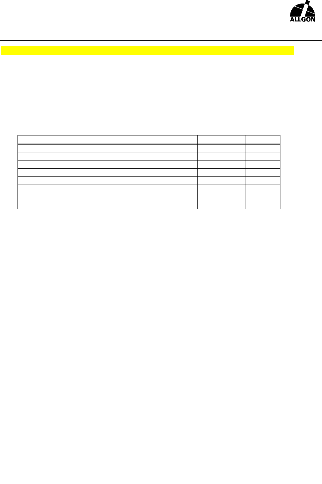
3.3 ABSOLUTE MAXIMUM RATINGS
The Absolute Maximum Rating is defined as the value of applied signal/power etc. that is guaranteed not
to damage the unit permanently. This applies over the full operating temperature range of the unit.
Parameter
MAX
MIN
Unit
3.1.1 Input DC Voltage (low imp. Source) - -70 V
3.1.2 Reverse Input DC Voltage 75 - V
3.1.3 Input Power on BTS port (TX-band) 40 - dBm
3.1.4 Input Power on ANT port (TX-band) 43 - dBm
3.1.5 Input Power on BTS port (RX-band) 20 - dBm
3.1.6 Input Power on ANT port (RX-band) 20 - dBm
3.1.7 Input Power on ANT port (other bands) 43 - dBm
3.1.8 Input Power on BTS port (other bands) 40 - dBm
3.4 GENERAL PARAMETERS
3.4.1 Nominal Impedance
Nominal impedance of all ports: 50Ω
3.4.2 Return Loss
Measured over the tuned Rx and Tx band.
Normal operation: Bypass:
BTS port: > 18 dB BTS port > 12 dB
ANT port: > 18 dB Ant port: > 12 dB
3.4.3 Power Consumption
Max: 130W (2.5A @48V)
Primary Fuse: 4 A Slow
3.4.4 Antenna Supervision (VSWR) (option 5)
This optionally feature monitors the Forward and Reflected power at the ANT port. If calculated
VSWR exceeds the VSWR LIMIT, a VSWR-alarm is issued. The VSWR value below is the
default value and is optionally software changeable from 2:1 to 5:1.
VSWR Return Loss
VSWR LIMIT: 2.5:1 ~7.4 dB
The VSWR-alarm is active down to an average output signal power > 20 dBm.
3.4.5 Reflected Output Power Supervision
If the reflected power from the antenna exceeds +38 dBm, the reflected power supervision
function will decrease the TX gain in order to limit the reflected power to a level less than
+38dBm. An RP_Alarm alarm will be issued in this condition .

ALLGON SYSTEM AB - Proprietary
Technical Specification for PCS Tower Top Power Amplifier [Allgon 9256]
Preliminary - Subjected to change without notice Rev.pA0
File: 93651 Page 11 (19) 29 Mar 00
3.4.6 Total Feeder DC Resistance and Maximum Feeder Length
Maximum length: 250 m (833 ft)
Maximum feeder DC resistance: 2Ω
Measured between the inner and outer connector with the other feeder end short circuited.
**Note: Only valid when using feeder cable for DC-feed.
3.4.7 Intermodulation Distorsion
The measurements are made on both ports with the TTPA operating at its nominal rated output
power and with:
Two interfering signals in the PCS-RX band at a power level of -40 dBm at ANT port.
One interfering signals in the PCS-TX band at a power level of +13 dBm at ANT port.
Maximum IMD level:
Band
ANT port
BTS port
Meas BW
RX -128 dBm -114 dBm 100 kHz
TX -70 dBc -70 dBc 100 kHz
3.5 TRANSMIT PATH PARAMETERS
3.5.1 TX Operating Frequency
-See section 2.1
3.5.2 TX Nominal Output Power
Measured at the ANT port, within the tuned TX band.
Min: +43 dBm (20W)
3.5.3 TX Overload Supervision
When the average Output Power exceeds 43 dBm with:
> 1.0 dB an TX-OP Minor Alarm (TX Over Power) alarm is issued
> 2.0 dB the TX power is soft limited by the AGC circuitry not to exceed this value.
and a TX-OP Major Alarm is issued.
3.5.4 TX Two Tone Linearity
Measured with two CW signals of 37dBm each (43dBm Peak Power) out from the unit in TX
band, giving 40dBm total average output power. Max 1MHz spacing between tones.
Level of IM-tones Max: -30dBc
3.5.5 TX Nominal Gain
Nominal Gain is defined as [MaxGain(inband) + MinGain(inband)] / 2
7dB
ALLGON SYSTEM AB - Proprietary
Technical Specification for PCS Tower Top Power Amplifier [Allgon 9256]
Preliminary - Subjected to change without notice Rev.pA0
File: 93651 Page 12 (19) 29 Mar 00
3.5.6 TX Gain Tolerance
Measured with AGC in operation.
Nominal gain ± 0.5 dB
3.5.7 TX Gain Ripple
Ripple is defined as [MaxGain(inband) - MinGain(inband)]
Max: 1 dB
3.5.8 TX AGC Operation
The AGC system continuously holds the TX-gain at nominal value.
If the system fails to regulate the power a PA-fail alarm is generated.
The AGC time constant is chosen to compensate for thermal and other long term drift.
Minimum average input power level for AGC operation: +20 dBm.
TX gain tolerance with AGC not operating: ±1.5dB.
3.5.9 TX Stability
The TX-amplifier is unconditionally stable for all passive loads at input and output.
3.5.10 TX Spurious Emissions and Broadband Noise
Measured at ANT port, with the TTPA operating at nominal output power.
Peak power and measurement bandwidth as listed in table.
Outside TX band:
Frequency band Max peak power / Bandwidth
RX band - 128 dBm / 100 kHz
1850-1910 MHz - 98 dBm / 100 kHz
824 - 849 MHz - 98 dBm / 100 kHz
100 kHz - 50 MHz - 36 dBm / 10 kHz
50-1000 MHz - 36 dBm / 100 kHz
1 – 12.75 GHz, outside TX band >+ 2 MHz - 30 dBm / 30 kHz
“ >+ 5
MHz - 30 dBm / 100 kHz
“ >+ 10
MHz - 30 dBm / 300 kHz
“ >+ 20
MHz - 30 dBm / 1 MHz
“ >+ 30
MHz - 30 dBm / 3 MHz
Inside TX band:
Frequency band Max peak power / Bandwidth
Carrier offset > + 1.8 MHz - 36 dBm / 30 kHz
Carrier offset > + 6 MHz - 36 dBm / 100 kHz

ALLGON SYSTEM AB - Proprietary
Technical Specification for PCS Tower Top Power Amplifier [Allgon 9256]
Preliminary - Subjected to change without notice Rev.pA0
File: 93651 Page 13 (19) 29 Mar 00
3.5.11 TX Bypass Loss (option 7)
TX bypass function is optional.
Measured from ANT to BTS port
Typ. 2.0 dB
Max: 2.6 dB
3.5.12 TX Redundancy & Bypass Operation
In the event of failure of one of the transistors in the power amplifier the gain will drop by
approx. 6dB. In this condition a TX-minor alarm will be generated. If both transistors fail and the
TX Bypass option is installed, the TX-path will be switched to bypass mode and a TX-major
alarm will be issued. Bypass mode will automatically be initiated if DC power to the PA fails.
3.6 RECEIVE PATH PARAMETERS
3.6.1 RX Operating Frequency
-See section 2.1
3.6.2 RX Gain
Nominal Gain is defined as [MaxGain(inband) + MinGain(inband)] / 2
13 dB
Optionally reduced in 1 dB steps from 13 to 7 dB.
3.6.3 RX Gain Tolerance
±0.6 dB
3.6.4 RX Gain Ripple
Ripple is defined as [MaxGain(inband) - MinGain(inband)]
±0.5 dB
3.6.5 RX Noise Figure
Measured at Nominal RX gain.
Typ: 1.9 dB
Max: 2.9 dB
3.6.6 RX Bypass Loss ( option 6 )
RX bypass function is optional.
Measured from ANT to BTS port
Typ. 2.2 dB
Max 2.9 dB
3.6.7 RX Input Intercept Point IIP3
Min: +6dBm

ALLGON SYSTEM AB - Proprietary
Technical Specification for PCS Tower Top Power Amplifier [Allgon 9256]
Preliminary - Subjected to change without notice Rev.pA0
File: 93651 Page 14 (19) 29 Mar 00
3.6.8 RX Stability
The RX-amplifier is unconditionally stable for all loads at input and output of the TTPA.
3.6.9 RX Redundancy
In the event of failure of one of the transistors in the balanced LNA the gain will drop by approx.
6dB. An RX-minor alarm will be generated. If both transistors fail, an RX-major alarm will be
generated.
3.7 FILTER PARAMETERS
Rx and Tx bands according to paragraph 2.1
Isolation ANT to LNA input
DC – 1000 90 dB
1000 – {35 MHz below Rx Band} 30 dB
1910 – 1990 50 dB
Tx Band (20 MHz wide) 85 dB
1990 – 5970 40 dB
5970 – 12750 20 dB
3.8 POWER SUPPLY PARAMETERS
3.8.1 Supply Voltage
- 48 Volts DC
3.8.2 Supply Voltage Tolerance
Measured at BTS port.
Max: -60V
Min: -40 V
3.8.3 Supply Voltage Noise Tolerance
! Ripple and noise 10Hz to 100 MHz: 100 mVp-p
! Wideband noise 4kHz to 20 MHz, any 3kHz band: 1V p-p
3.8.4 DC/DC Redundancy (option 4)
The power supply consists of two DC/DC converters in parallel, sharing the current. In the case
off one converter failing, the remaining converter will power the unit to full operation. An alarm
(DC-minor) will be signaled to the PDU. If both DC/DC converters fails, or no power is applied to
the unit, the APDU detects this automatically and raises an alarm.
3.8.5 DC Input Protection
! Reverse Voltage Protection
! Over voltage Protection ( see lightning spec.)
! Over current protection

ALLGON SYSTEM AB - Proprietary
Technical Specification for PCS Tower Top Power Amplifier [Allgon 9256]
Preliminary - Subjected to change without notice Rev.pA0
File: 93651 Page 15 (19) 29 Mar 00
3.8.6 Inrush Current
Measured at power on with nominal supply voltage.
Max peak: 15A
Max after 10ms: 3A
4 MECHANICAL SPECIFICATION
4.1 PHYSICAL PARAMETERS
4.1.1 Height
350 mm (±20mm)
4.1.2 Width
220 mm (±20mm)
4.1.3 Depth
230 mm (±20mm)
4.1.4 Volume
17 dm3
4.1.5 Weight - Clamping Unit
3 kg
4.1.6 Weight - Amplifier Unit
12 kg (26.5 lb)
4.1.7 Color
RAL 7035 and Nature Anodized Aluminum, non reflective.
4.1.8 Wind Load
~155 N @ 150 km/h (41.67 m/s)
4.1.9 Materials
All plastic materials are characterized according to ISO 1043.
4.1.10 Weatherproofing
UL50/IP 65
4.2 INTERFACES
The TTPA has total of two (2) ports designated BTS and ANT. The BTS Connector carries the signals
to/from the BTS rack (e.g. TX-in, RX-out, DC-power and Alarm signaling). The ANT connector should be
connected to the antenna.

ALLGON SYSTEM AB - Proprietary
Technical Specification for PCS Tower Top Power Amplifier [Allgon 9256]
Preliminary - Subjected to change without notice Rev.pA0
File: 93651 Page 16 (19) 29 Mar 00
4.2.1 BTS Connector
7/16 Female
4.2.2 ANT Connector
7/16 Female
4.2.3 Earthing
Earthing stud: M8 x 15mm
4.2.4 DC Connector (option 2)
Optional DC connector for separate DC, see 2.2
Type: Binder series 623 , 6 poles, male
4.2.5 Alarm Connector (option 3)
Optional alarm connector, see 2.2
Type: Binder series 623 , 12 poles, male
4.2.6 Power ON LED
Optional LED, indicating POWER ON
Color: Green
4.3 MOUNTING
NOTE: DC power must be connected to the TTPA within one day after mounting to prevent
damage due to moisture.
4.3.1 Mounting method
The TTPA is equipped with a pole clamping unit. This enables the installation personnel to first
install the relatively light mast clamp, and then easily hook on the actual amplifier. This feature
reduces the risk of accidents during installation.
! Pole mounting with clamps. Pole diameter: 50 - 120 mm
! Wall mounting by means of mounting plate.
4.3.2 Mounting Time
The unit is designed to be easily mounted by normally skilled installation personnel in less than
20 minutes. (Not including commissioning )
4.3.3 Mounting Requirements
! The unit must have non obstructed free air to a distance of 0.5m from TOP and BOTTOM
sides, and 0.2 m from all other sides, except BACK side.
! Mounting angle: Vertically ±10° (Applies to completed mounting, TTPA in operation)
4.3.4 MTTR
Less than 15 min (excluding commissioning )

ALLGON SYSTEM AB - Proprietary
Technical Specification for PCS Tower Top Power Amplifier [Allgon 9256]
Preliminary - Subjected to change without notice Rev.pA0
File: 93651 Page 17 (19) 29 Mar 00
5 ENVIRONMENTAL SPECIFICATION
5.1 OPERATING CONDITIONS
( Conditions: The unit mounted in free air, DC power applied at all times.)
5.1.1 Ambient Air Temperature Full Performance
Max: + 50 °C
Min: - 35 °C
5.1.2 Survival Operational Temperature
Max: + 80 °C
Min: - 40 °C
When the internal temperature exceeds +80°C the power is reduced and the transmission path
goes into bypass mode. Resets automatically when the temperature decreases.
5.1.3 Relative Humidity
Max: 100 %
Min: 8 %
5.1.4 Absolute Humidity
Max: 30 g/m3
Min: 0.26 g/m3
5.1.5 Rate of Temperature Change
Max: 1°C/min (ambient)
5.1.6 Air Pressure
Max: 106 kPa
Min: 70 kPa
5.1.7 Solar Radiation
Max: 1125 W/m2 (with solar cover)
5.1.8 Vibration
According to: ETS 300 019-2-4
5.1.9 Applicable Test Standards
ETS 300 019-2-4 class T4.1
80 / 85 environmental test
5.2 STORAGE AND TRANSPORTATION
( Conditions: 6 months storage of unit in original shipping container with intact sealing )
5.2.1 Ambient Air Temperature
Max: + 85 °C
Min: - 45 °C

ALLGON SYSTEM AB - Proprietary
Technical Specification for PCS Tower Top Power Amplifier [Allgon 9256]
Preliminary - Subjected to change without notice Rev.pA0
File: 93651 Page 18 (19) 29 Mar 00
5.2.2 Relative Humidity
Max: 100 %
Min: 8 %
5.2.3 Absolute Humidity
Max: 30 g/m3
Min: 0.26 g/m3
5.2.4 Rate of Temperature Change
Max: 2°C/min (ambient)
5.2.5 Air Pressure
Max: 106 kPa
Min: 50 kPa
5.2.6 Vibration
According to: ETS 300 019-2-1
ETS 300 019-2-2
IEC 68-2-6
IEC 68-2-36
IEC 68-2-29
IEC 68-2-32
5.2.7 Applicable Test Standards
Transport: ETS 300 019-2-2 class T2.3
Storage: ETS 300 019-2-1 class T1.2
5.3 ELECTROMAGNETIC COMPATIBILITY (EMC)
Complies to: ETS 3000 342-2
IEC 1000-4-5
FCC Part 24
FCC Part 15
5.4 LIGHTNING PROTECTION
According to IEC 1000-4-5 extended to 10 kA short circuit current.
ANT port DC grounded
6 RELIABILTIY SPECIFICATION
6.1 OPERATING LIFE
The TTPA is designed for an operating life exceeding 10 years.
6.2 THEORETICAL MTBF
Theoretical MTBF is calculated according to MIL-HDBK-217F, part stress method, ground fixed,
uncontrolled environment, 40°C ambient temperature. If available, practically derived reliability data is
used in place of statistical in the calculation. This calculation yields an MTBF of > 25000 hours.

ALLGON SYSTEM AB - Proprietary
Technical Specification for PCS Tower Top Power Amplifier [Allgon 9256]
Preliminary - Subjected to change without notice Rev.pA0
File: 93651 Page 19 (19) 29 Mar 00
Note: the calculated MTBF gives a very conservative value. Especially when the components MTBF is
based on the default data specified in MIL-HDBK-217F and not from an accelerated life time test. If
such data was available on every component then a result close to the field proven MTBF could be
calculated.
6.3 FIELD PROVEN MTBF
The TTPA is designed to demonstrate a field proven MTBF of over 200000 hours, calculated over a
period exceeding one (1) year.
7 SAFETY SPECIFICATION
7.1 TOXIC MATERIALS
No toxic materials is used within the unit.
7.2 SAFETY CLASSIFICATIONS
CE-Recognition: EN 60950
UL-Classification: UL 1950
8 SERVICE AND MAINTENANCE
8.1 SERVICE
No field serviceable parts inside. Failed unit must be returned to Allgon.
Service only by qualified personnel authorized by Allgon.
8.2 MAINTENANCE
No periodic maintenance necessary.