Powerwave Technologies 922802 User Manual Inst guide TTPA draft
Powerwave Technologies Inc. Inst guide TTPA draft
Users manual
TTPA Installation Guide
(draft version)
Disclaimer
The information contained in this publication has been carefully reviewed to ensure it’s accuracy.
However, since the possibility for errors can never be entirely eliminated, Allgon System AB
assumes no responsibility for any inaccuracies or errors in the information contained herein. This
information does not convey to the purchaser or user of any product described in this publication
any license under any patent, copyright, trade secret or other intellectual property, unless otherwise
stated by written agreement by Allgon System AB. Allgon System AB, and it’s affiliates, reserve
the right to change any specification, design, model and any other information contained herein
without notice.
Allgon System AB does not assume any liability arising out of, or associated with, the application
or use of any product or item described herein. The products from Allgon System AB are not
designed, intended or authorized, for use as components in systems or applications intended to
support or sustain life, or for any nuclear facility application, or for any other application in which
the failure of the product(s) could create a situation where personal injury or death may occur.
Allgon System AB will not knowingly sell it’s products for use in such applications, and the buyer
shall indemnify and hold harmless Allgon System AB and it’s employees, subsidiaries, affiliates,
representatives and distributors against all claims, costs, damages, expenses, court and attorney
fees arising out of, directly or indirectly, any claim of personal injury or death associated with such
unintended or unauthorized use, even if such claim alleges that Allgon System AB was negligent
regarding the design or manufacture of the product.
Contents
1. General Information 4
Overview 4
Safety Considerations 4
2. Installation of the TTPA 2
Outdoor conditions 2
Dimensions 2
Mounting equipment 2
Checklist before mounting and installation 2
Installation procedure for TTPA 2
Checklist after mounting and installation 4
3. Installation of CI 5
General 5
Outdoor and indoor conditions 5
Mounting equipment 5
Checklist before mounting and installation 5
Installation procedure for CI 5
Checklist after mounting and installation 6
4. Installation of APDU 6
General 6
Outdoor and indoor conditions 6
Dimensions 7
Mounting equipment 7
Checklist before mounting and installation 7
Installation procedure for APDU in BTS 8
Checklist after mounting and installation 8
5. Commissioning 8
Appendix 1. TTPA Software Settings 9
Optimising coverage 9
General link budget characterisation, step by step 9
Appendix 2: System Configuration Examples 11
Configuration I 11
Configuration II 12
Configuration III 13
Configuration IV 14
Acronyms and Abbreviations
APDU Alarm and Power Distribution Unit
BTS Base Tranceiver System
CI Current Injector
DMM Digital Multi Meter
ESD Electro Static Discharge
LED Light Emitting Diod
LNA Low Noise Amplifier
MTBF Mean Time Between Failures
MTTR Mean Time To Replace
NF Noise figure
TTA Tower Top Amplifier
TTPA Tower Top Power Amplifier
1. General Information
Overview
The physical installation of each part of the TTPA system is described in separate
chapters. Testing and functioning check is described in a separate chapter. Different
kinds of system configurations are described in the last chapter.
Note that at some stages during the installation, the BTS must be turned off. To
prevent extensive downtime it may be useful to finish the stages of the installation of
both TTPA, APDU and CI when the BTS still is active. The BTS then has to be shut
down only once for finishing the installation of all included parts.
Note that all information in this manual may change without any notice. Refer to the
technical specifications for the latest information on the TTPA products.
Safety Considerations
The TTPA is equipped with a pole clamping unit. This enables the installation
personnel to first install the relatively light mast clamp, and then easily hook on the
actual amplifier. This feature reduces the risk of accidents during installation.
It is important for everyone involved in the installation, operation, and maintenance of
the TTPA, APDU and CI to understand the following points:
•The TTPA, APDU, and CI are designed to amplify the uplink signal from the
mobile phone and the downlink signal to the mobile phone. The TTPA system
must be used exclusively for this purpose and no other.
•No units included in the system (TTPA, APDU or CI) may be repaired in the
field. All malfunctioning parts must be sent back to Allgon Systems for repair or
replacement.
•Always use an ESD bracelet during installation of electrical equipment and when
touching the BTS connectors, or when handling electrical equipment, to prevent
ESD damage.
•The mounting of the TTPA on high masts, poles or roofs must be done by skilled
personnel, authorised to work on high masts, poles, or roofs. The personnel must
be aware of security regulations and use appropriate security equipment.
•The coaxial cable insulation is made of PTFE, polytetrafluoroethylene, which
gives off small amounts of hydrogen fluoride when heated. Hydrogen fluoride is
poisonous. Heating tools must not be used when stripping off coaxial cable
insulation. No particular measures are to be taken in case of fire, because the
emitted concentration of hydrogen fluoride is very low.
2. Installation of the TTPA
Outdoor conditions
The TTPA is environmentally protected (IP 65), and can be mounted without any kind
of protection from bad weather conditions. However, it is not permitted to install the
TTPA in bad weather conditions. If the bad weather conditions are of a short
duration, and the TTPA and all other connectors that are to be connected during the
installation are protected, the installation may continue not less than one hour after the
adverse conditions have ended.
Dimensions
Weight is 12 kilos for TTPA unit, 3 kilo for clamping unit.
Mounting equipment
A standard mounting kit is delivered with each TTPA. It contains one holder used for
both pole mounting and wall mounting, and screws needed for the mounting. The
brackets for pole mounting fit poles with diameters of between 50 and 120 mm.
A torque meter is needed for tightening bolts and connectors. Amalgamated tape for
insulating the connectors is not required, but may be used.
Checklist before mounting and installation
•Are all the necessary adapter cables available and are they long enough?
Normally, a 1 meter long adapter cable is needed for the connection between the
TTPA and the antenna.
•Are the 7/16 connectors to be connected to the TTPA of the correct sex?
•Are brackets of the right size available?
•Are sufficiently long grounding straps available?
•Is the place where the TTPA is to be mounted the optimal location, considering
cable lengths and length of grounding straps?
•Is there a distance of free air of at least 0.5m from top and bottom sides, and 0.2
m from all other sides except the backside?
Installation procedure for TTPA
Before the actual installation is started, read the safety information at the beginning of
this guide.
Phase 1: The first phase of the installation, that is the mounting of the TTPA and
grounding cable, can be carried out with the BTS still active.
If the TTPA unit is to be mounted on a wall, you’ll need to take away the four tabs
for pole mounting on the mounting plate (see picture below). The easiest way is to
bend them away with a pair o pliers.
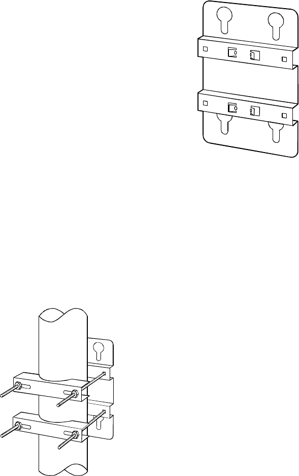
Figure 1: Mounting plate
•Attach the mounting plate for the TTPA to the wall or the mounting pole. Use the
clamps or screws and plastic plugs provided with the unit. The cable connectors of
the unit must be on the bottom side of the unit. Tilt must not exceed 10 degrees.
Pole mounting: Note that the inner nut (with a flange) is kept in position while it
is locked by the outer nut.
Wall mounting
: Note that the holes shall be 10 mm in diameter, and about 60 mm
deep, and that the plastic plugs included in the mounting kit shall be used.
Figure 2: Pole mounting
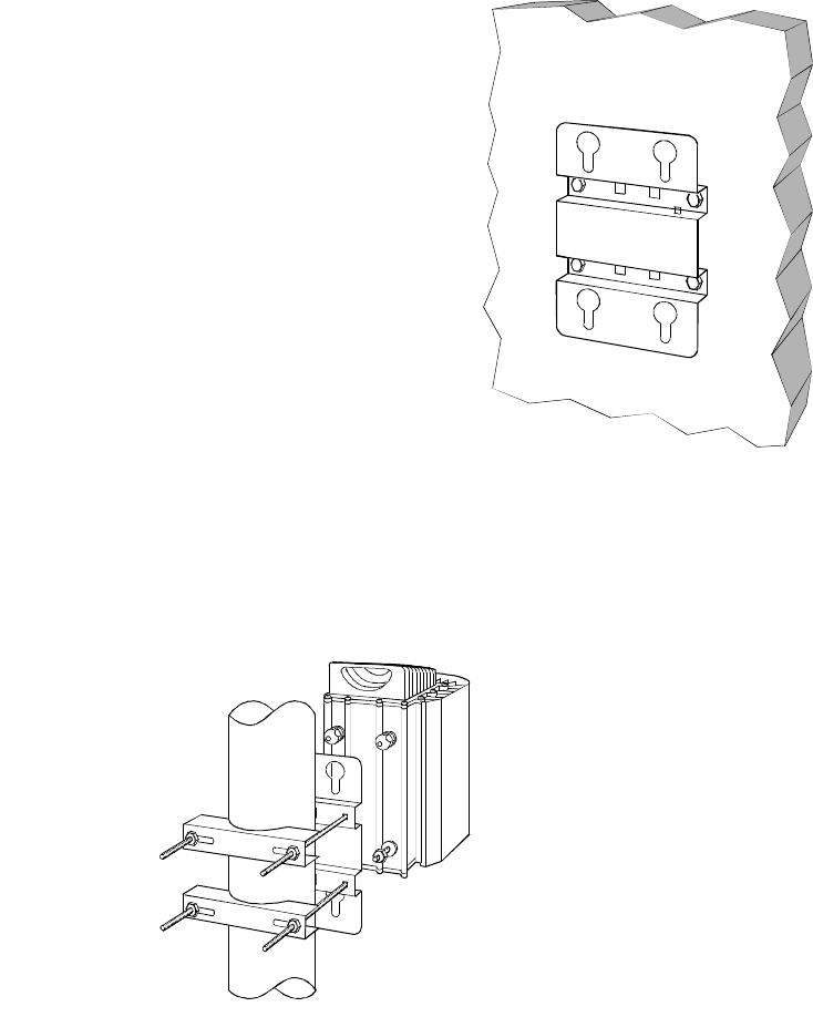
Figure 3:
Wall mounting
•Attach the TTPA to the mounting plate according to the figure below. When the
TTPA has been mounted on the plate, press it downwards until it sticks. Tighten
the two bottom nuts.
Figure 4: Attaching the TTPA to the mounting plate
•Ground the unit through a grounding strap, mounted to the ground screw and a
ground connection on the pole or mast, or to the ground cable between antenna and
earth.
Phase 2:
The second phase of the installation, that is the attachment of cables between
antenna and TTPA, and TTPA and BTS, must be carried out with the BTS shut
down.
•Shut down the BTS.
•Attach the cable between antenna and TTPA, and between TTPA and BTS.
Often there is a low loss feeder between the BTS and the antenna, with the feeder
attached to the antenna using an adapter cable. If this is the case, it may be easier
to disconnect the feeder and adapter cable from the antenna and attach it to the
TTPA. Then connect the TTPA to the antenna using the short cable. If the feeder
is attached directly to the antenna, or is easy to move, then it may be connected
directly to the TPPA. Always first attach the cables to the connectors by hand,
then use the torque meter to tighten the cables to 25 Nm. It is important that the
torque does not exceed 30 Nm because of the risk of damage to the connectors.
make sure that the antenna cable is connected to the ANT connector, and the BTS
cable to the BTS.
Checklist after mounting and installation
•Check that the brackets or wall holders are properly tightened.
•Are the grounding straps connected and the screws tightened?
•Are all 7/16 connectors connected and tightened to 25 Nm (or by hand, if no
torque meter is available)?
•Check that the feeder has not been forced to connect to the TTPA.
•Applicable if no CI is used: Are the DC cables connected to the TTPA DC
connectors?
Note: The TTPA must be powered on within one day after unpacking and mounting,
to prevent malfunction and damage due to moisture.
3. Installation of CI
General
Note that at some stages during the installation, the BTS must be turned off. To
prevent extensive downtime it may be useful to finish the first stages of the
installation of both TTPA, APDU and CI when the BTS still is active. The BTS then
has to be shut down only once for finishing the installation of all included parts.
Outdoor and indoor conditions
The CI can be installed both indoors and outdoors. Normally, it will be strapped to a
cable ladder or equivalent. It is environmentally protected (IP 65), and can be
mounted without any kind of protection from bad weather conditions. However, it is
not permitted to install the CI outdoors in bad weather conditions. If the bad weather
conditions are of a short duration, and the CI and all other connectors that are to be
connected during the installation are protected, the installation may continue not less
than one hour after the adverse conditions have ended.
Information on environmental requirements for the CI is found in the Reference
Manual.
Mounting equipment
•Crimp tool
•Torque meter
Checklist before mounting and installation
•Check that the CI is of the right type. Note that the TTPAs and TTAs must be
connected with different CIs:
TTA: 8478.xx, 8484.xx, 9184.xx or 9221.xx, for 12 VDC
TTPA: 9219.xx, for 48 VDC
•Are the correct cables with the correct connectors and lengths present?
•Is the ground cable present?
•Are straps to secure the CI available?
Installation procedure for CI
Example of CI. Please note that
connectors and connector gender may differ between the versions.
The Current Injector is weatherproof and can be mounted indoors or outdoors. Therre
is no equipment for mounting the CI to walls or antenna tower, as it will form an
integrated part of the TTPA cabling.
With the BTS still active:
1. Connect the antenna cable to the antenna port on the CI.
2. Connect the BTS cable to the BTS port on the CI.
3. Connect the grounding cable to a suitable grounding point (e.g. same as ADPU).
4. Connect the DC cable from the ADPU to the DC port on the CI.
Checklist after mounting and installation
•Check that the grounding straps (if used) are connected and the screws tightened?
•Are all 7/16 connectors connected and tightened to 25 Nm (or by hand, if no
torque meter is available)?
•If you are using amalgamating tape to seal off the connectors, check that this is
done.
4. Installation of APDU
General
Note that at some stages during the installation, the BTS must be turned off. To
prevent extensive downtime it may be useful to finish the first stages of the
installation of both TTPA, APDU and CI where the BTS still is active. The BTS then
has to be shut down only once for finishing the installation of all included parts.
Outdoor and indoor conditions
The APDU can be installed both indoors and outdoors. It is mounted in a
environmentally protected (IP 65) lockable box, and can be mounted without any
kind of protection from bad weather conditions. However, it is not permitted to install
the APDU outdoors in bad weather conditions. If the bad weather conditions are of a
short duration, and the APDU and all other connectors that are to be connected during
the installation are protected, the installation may continue not less than one hour after
the adverse conditions have ended.
Information on environmental requirements for the APDU is found in the Reference
Manual.
Dimensions
Figure x: APDU box (dimensions 200x300x150mm)
Mounting equipment
The APDU is mounted on the same kind of mounting plate as the TTPA. Check the
TTPA mounting instructions for how to attach the mounting plate to the wall, and the
ADPU to the mounting plate.
Checklist before mounting and installation
•Check that the CI (Current Injector) is of the right type. Note that the TTPAs and
TTAs must be connected with different CIs:
TTA: 8478.xx, 8484.xx, 9184.xx or 9221.xx, for 12 VDC
TTPA: 9219.xx, for 48 VDC
•Is 48VDC or 115/230 VAC supply available?
•Does the supply cable for the APDU have the correct connector on the BTS side?
•Are the correct cables with the correct connectors between APDU and Current
Incector available and are they long enough?
•Is the necessasy equipment and material to connect the alarm cable to the BTS
external alarms available?
•Is the alarm cable of the correct type?
•Are a ground wire or heavy duty crimp terminals, cable and a crimp tool
available?
•Are the 7/16 connectors to be connected to the CI of the correct sex?
•Are the DMM, cable ties and all the necessary tools available?
Installation procedure for APDU in BTS
Before the actual installation is started, read the safety information at the beginning of
this guide.
Phase 1: This part of the installation can be carried out without switching off the
BTS.
//picture of APDU connectors with explanation//
•Mount the APDU in its predefined location.
•Connect the APDU to the grounding point.
•Connect the supply cable to the APDU DC (or AC) input with the correct
polarity.
•Connect the cable between APDU and CI.
•Connect the alarm cable between APDU and BTS to the APDU.
Phase 2
: The second phase of the installation, that is the attachment of cables between
APDU and BTS, may have to be carried out with the BTS shut down. Check with the
BTS supplier.
•Connect the supply cable to the BTS 48 V or 220 V supply.
•Connect the alarm cable to the BTS.
An example of software configuration of the TTPA is dealt with in the Software
Configuration of System chapter below.
Checklist after mounting and installation
•Check that the brackets or wall holders are properly tightened.
•Check that the grounding straps are connected and the screws tightened?
•If you are using amalgamating tape to seal off the connectors, check that this is
done.
5. Commissioning
To be added
Appendix 1. TTPA Software Settings
Optimising coverage
The TTPA can optionally be equipped with soft gain control, both for up- and down
link (i.e. receive and transmit branch). By carefully tuning the gain for each branch it
is possible to significantly improve the coverage provided by the BTS.
In order to optimise the coverage with the TTPA soft gain control it is necessary to
first characterise the particular BTS regarding the balance of the link budget, i.e. the
distance covered by the BTS transmitter compared to the talk back distance of the
mobile terminal. The unbalance, Pub, and the feeder loss must be available to use the
TTPA soft gain settings in an optimum way.
If the TTPA is deployed as a retrofit, there is a good chance that such a

characterisation already exists and that the BTS is balanced from a link budget point
of view. If this is the case, skip step 1 in General link budget characterisation, step by
step below and continue to step 2 or 3.
General link budget characterisation, step by step
1. Measure site link balance
2. Measure site feeder loss
3. Calculate theoretical maximum TTPA sensitivity gain
4. Add link balance and sensitivity gain to decide TTPA Tx gain
5. Set TTPA Tx and Rx gain
6. Measure site link balance to verify gain settings
1. To characterise the actual link budget in a cell, specific equipment is needed. This
can be provided by the infrastructure supplier or the net planner. In general, a vehicle
mounted channel monitor is needed, together with the BTS channel monitor.
The quality can be characterised by many different parameters and the choice should
not affect the results. Below, RBER (Residual Bit Error Rate) have been used. A
common quality setting is that the RBER should be <2%.
Place a call from a place well within the area covered by the BTS and slowly move
towards the cell border while monitoring the call quality at both terminal and BTS.
When RBER=2% for either the down link (monitored in the vehicle) or the up link
(monitored in the BTS), stop the vehicle.
If the up link is limiting, i.e. RBER=2% is monitored in the BTS:
The terminal should now be transmitting at its full power. Note the output power of
the BTS, P0. Decrease the BTS output power step by step until RBER=2% is
monitored in the vehicle. Note the output power of the BTS, P1. The unbalance is
given by:
P1 - P0 = Pub (Pub should be <0)
If the down link is limiting, i.e. RBER=2% is monitored in the vehicle:
The BTS should now be transmitting at its full power. Note the output power of the
terminal, P0. Decrease the terminal output power step by step until RBER=2% is
monitored in the BTS. Note the output power of the terminal, P1. The unbalance is
given by:
P0 - P1 = Pub (Pub should be >0)
2. Meassure the feeder length and use the manufacturers typical loss per meter data to
decide the site feeder loss, L (any other method will do as long as a value for the
feeder loss is present….).
3. The LNA in the TTPA will significantly improve the BTS sensitivity. How much is
easily calculated by using Friis’ formula. Input parameters are, apart from TTPA Rx
gain (GRx ) and noise figure (NFRx), site feeder loss, L, and BTS transceiver input
noise figure, NFT. The total system noise figure before and after deployment of the
TTPA will be:
With no TTPA:
NFBTS1 = L + NFT
With TTPA:
NFBTS2 = NFRx + (L - 1)/GRx + (NFT -1)L/GRx
Hence, the sensitivity improvement will be NFBTS1 - NFBTS2 = SG.
The value of SG can also be calculated using the free Allgon LinkPlanner tool.
4. Now it is possible to calculate the gain setting of the TTPA Tx branch, GPA to
maximise cell coverage:
Pub + SG = GTx
Please note that the two gain values are valid only if the original BTS output power
setting remains.
It is possible that the receiver sensitivity improvement is so large that there is not
enough Tx gain available to balance the link budget. Such a scenario is possible on
sites where the feeder loss is extremely high. In such cases the sensitivity gain, SG,
must be reduced to balance the maximum value of the TTPA Tx gain, GTx,max and the
link balance value Pub:
SG = GTx,max - Pub
SG is reduced by decreasing the value of the TTPA Rx gain, GRx, in Friis’ formula.
5. Set the TTPA values of GTx and GRx through the APDU user interface.
6. To verify the new cell coverage and link balance, repeat step 1 above. If done
correctly the value of Pub should read very close to 0.
Appendix 2: System Configuration Examples
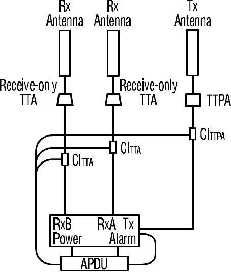
Configuration I
One duplexed antenna and one diversity receive antenna with duplex filter in BTS.
Power fed via single port Current Injectors.
Equipment for one three sector site:
3 TTPA (one per sector)
3 Receive-only TTA (one per sector) 3 single port Current injectors for TTPA 3 single port
Current injectors for TTA 1 APDU
Equipment for one two sector site:
2 TTPA (one per sector)
2 Receive-only TTA (one per sector) 2 single port Current injectors for TTPA 2 single port
Current injectors for TTA 1 APDU
Equipment for one omni site:
1 TTPA
1 Receive-only TTA 1 single port Current injectors for TTPA 1 single port Current injectors for
TTA 1 APDU
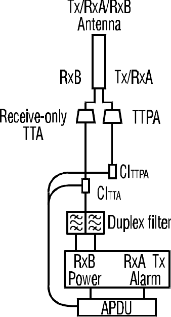
Configuration II
One dual polarized duplexed antenna with duplex filter in BTS. Power fed via single
port Current Injectors. A Duplex TTA could be preferred in stead of the Receive-only
TTA as this will prepare the system for a build out with another transceiver.
Equipment for one three sector site: 3 TTPA (one per sector)
3 Receive-only TTA (one per sector) 3 single port Current injectors for TTPA 3 single port
Current injectors for TTA 1 APDU
Equipment for one two sector site: 2 TTPA (one per sector)
2 Receive-only TTA (one per sector) 2 single port Current injectors for TTPA 2 single port
Current injectors for TTA 1 APDU
Equipment for one omni site: 1 TTPA
1 Receive-only TTA 1 single port Current injectors for TTPA 1 single port Current injectors for
TTA 1 APDU
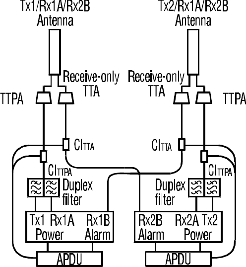
Configuration III
Two dual polarized duplexed antennas with duplex filters in BTS. Power fed via
single port Current Injectors. Instead of using e.g. one 8-ch. combiner, two 4-ch.
combiners can be used, distributing the Tx-signals over two Duplex antennas. The
insertion loss and power handling (heat sink & peak power) will be more
advantageous. A Duplex TTA could be preferred in stead of the Receive-only TTA as
this will prepare the system for a build out with another transceiver.
Equipment for one three sector site: 6 TTPA (two per sector) 6 Receive-only
TTA (two per sector) 6 single port Current injectors for TTPA 6 single port Current injectors for
TTA 2 APDU
Equipment for one two sector site: 4 TTPA (two per sector) 4 Receive-only
TTA (two per sector) 4 single port Current injectors for TTPA 4 single port Current injectors for
TTA 2 APDU
Equipment for one omni site: 2 TTPA 2 Receive-only TTA 2 single
port Current injectors for TTPA 2 single port Current injectors for TTA 1 APDU
Configuration IV
One transmit antenna and two receive antennas (main and diversity). Power fed via
single port Current Injectors.
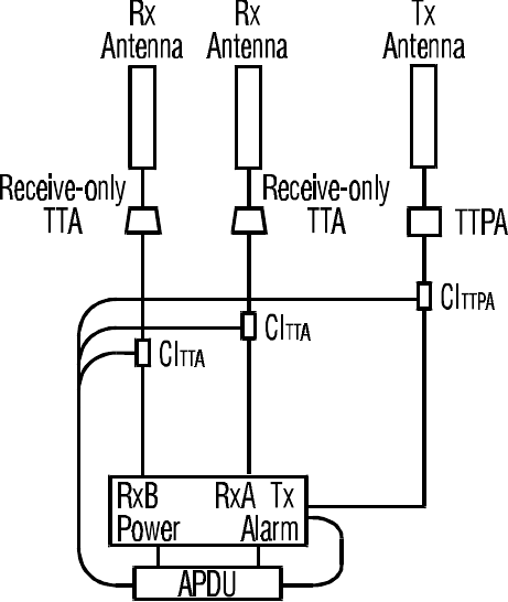
Equipment for one three sector site:
3
TTPA (one per sector) 6 Receive-only TTA (two per sector) 3 single port Current injectors for
TTPA 6 single port Current injectors for TTA 2 APDU
Equipment for one two sector site:
2 TTPA (one per sector) 4 Receive-only TTA
(two per sector) 2 single port Current injectors for TTPA 4 single port Current injectors for TTA
2 APDU
Equipment for one omni site: 1 TTPA 2 Receive-only TTA 1 single port
Current injector for TTPA 2 single port Current injectors for TTA 1 APDU