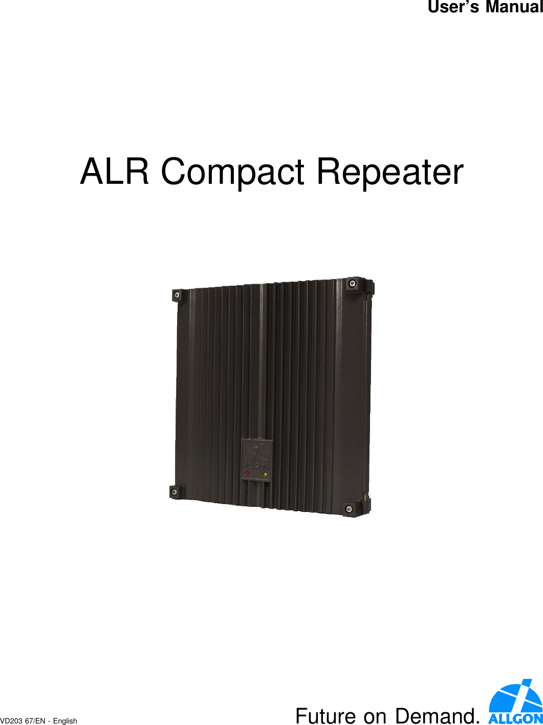
Powerwave Technologies ALR4600 Frequency Selective Repeater User Manual ARL Compact Repeater User s Manual
Powerwave Technologies Inc. Frequency Selective Repeater ARL Compact Repeater User s Manual
Contents
- 1. users manual
- 2. users manual attachment
- 3. additional manual page
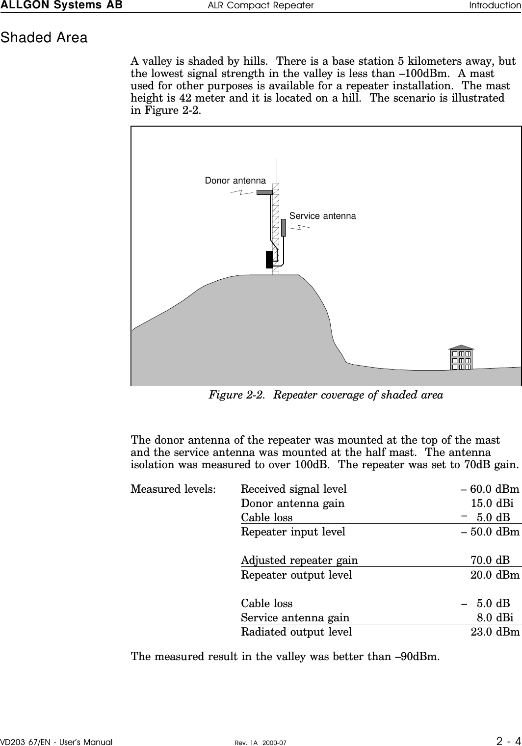
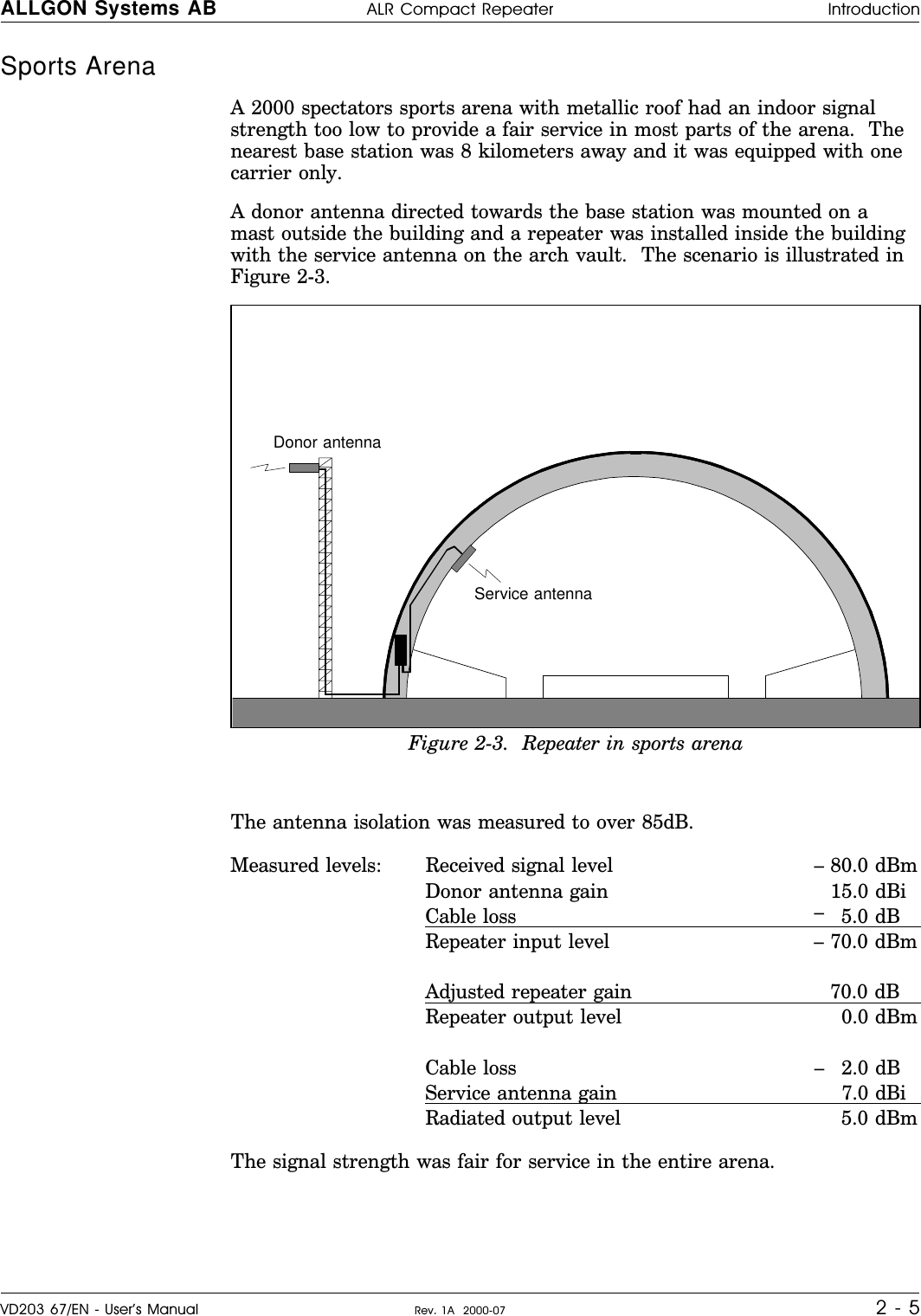
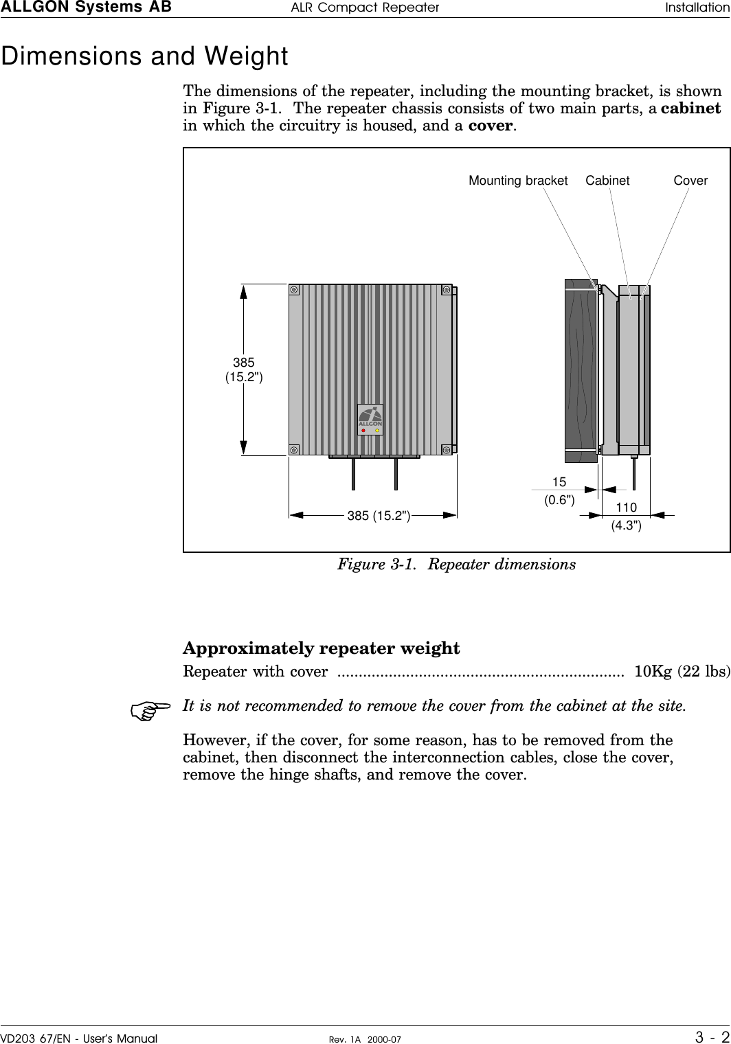
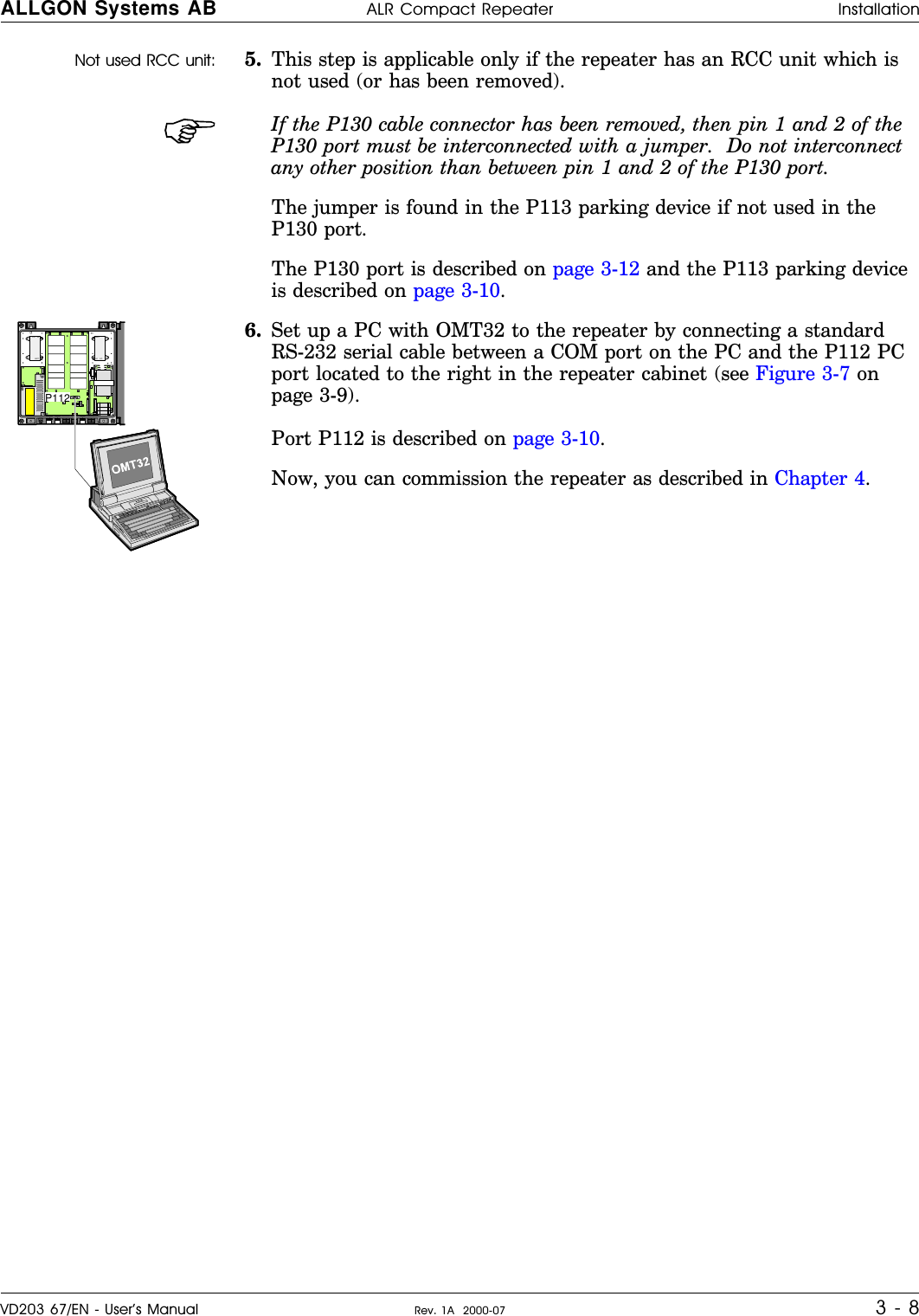
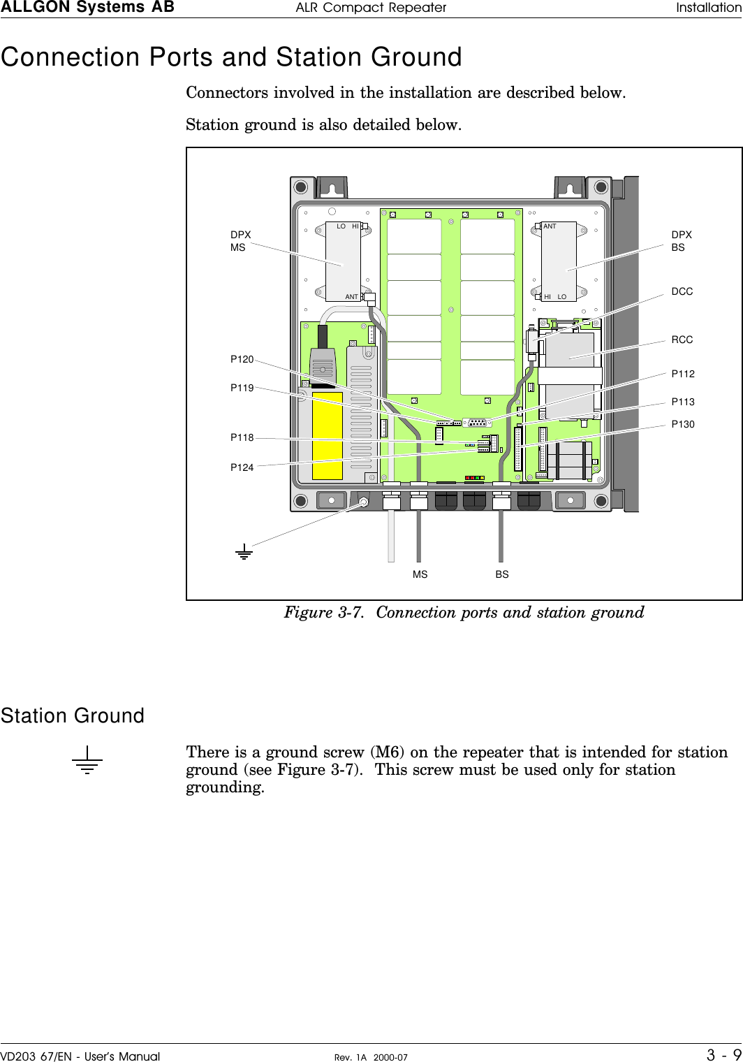
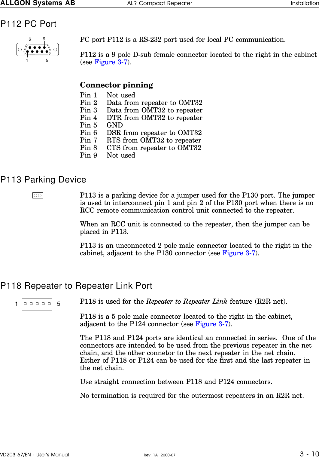
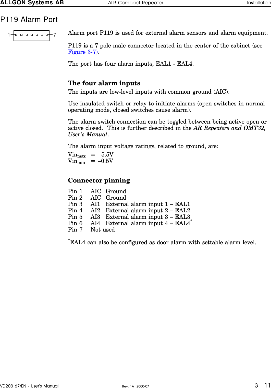
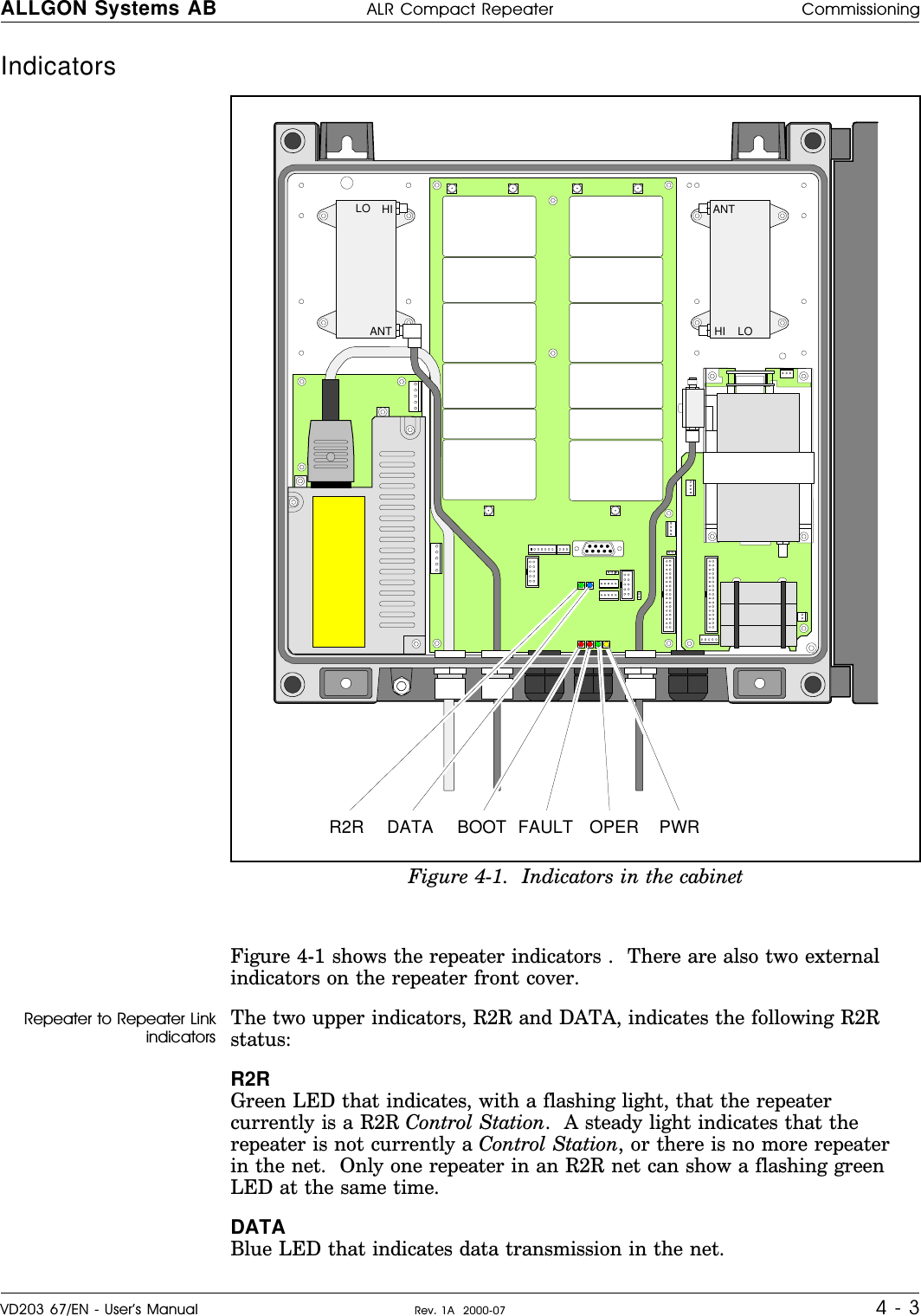
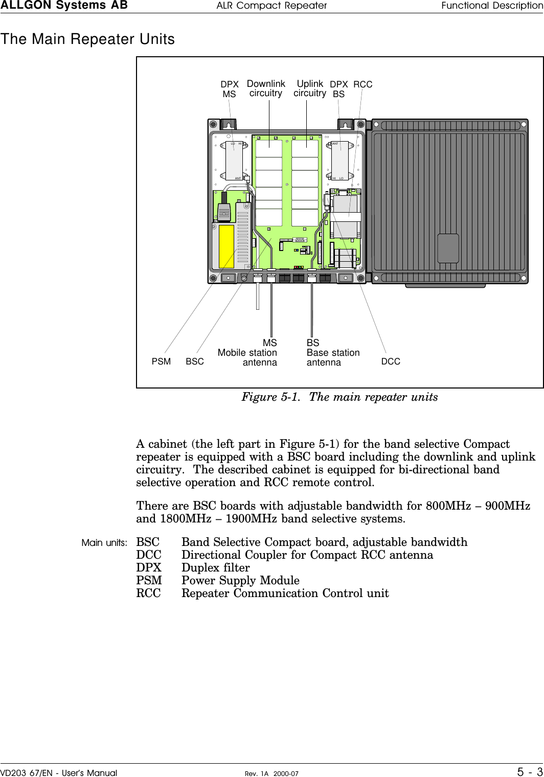
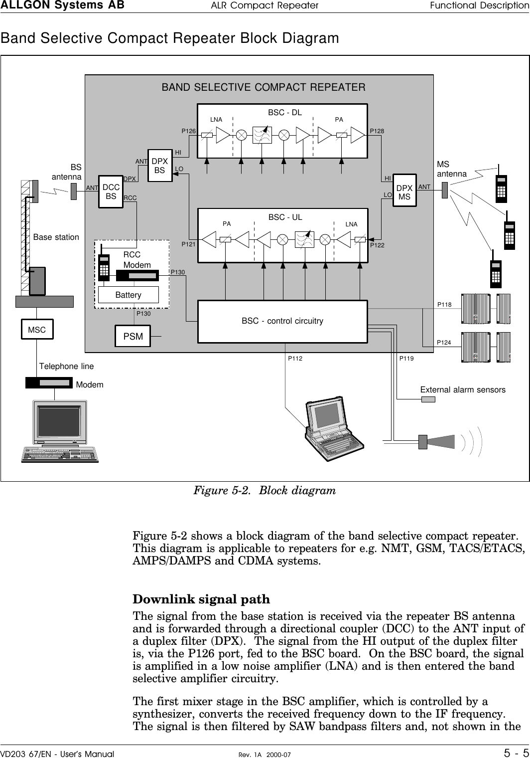
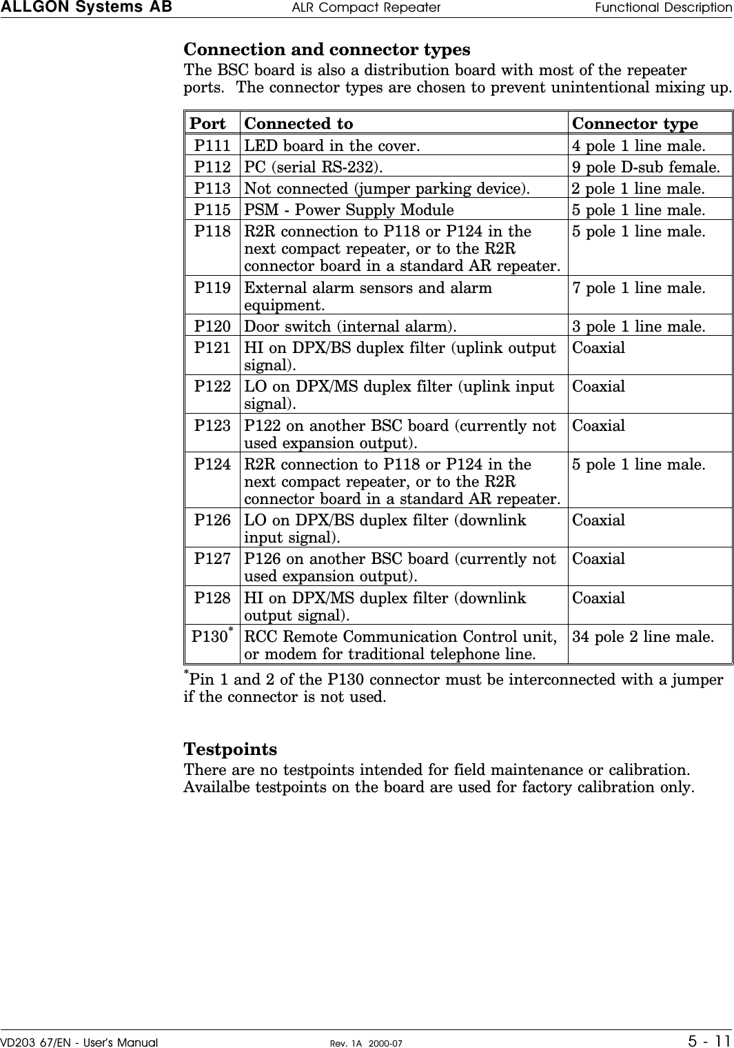
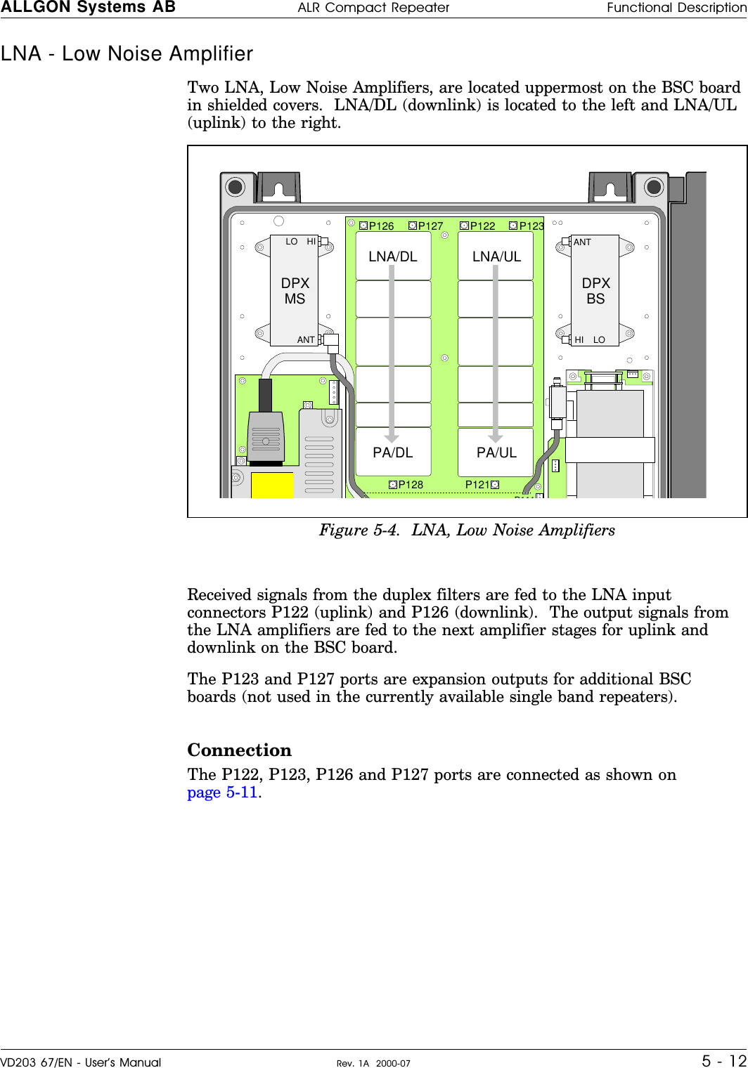
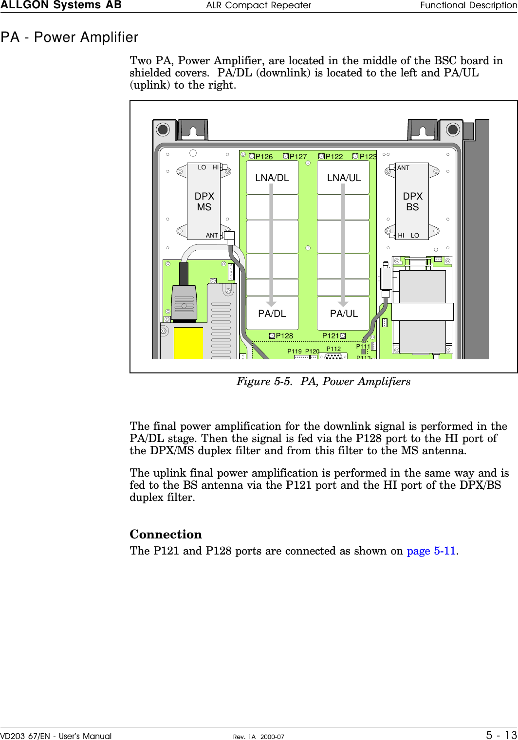
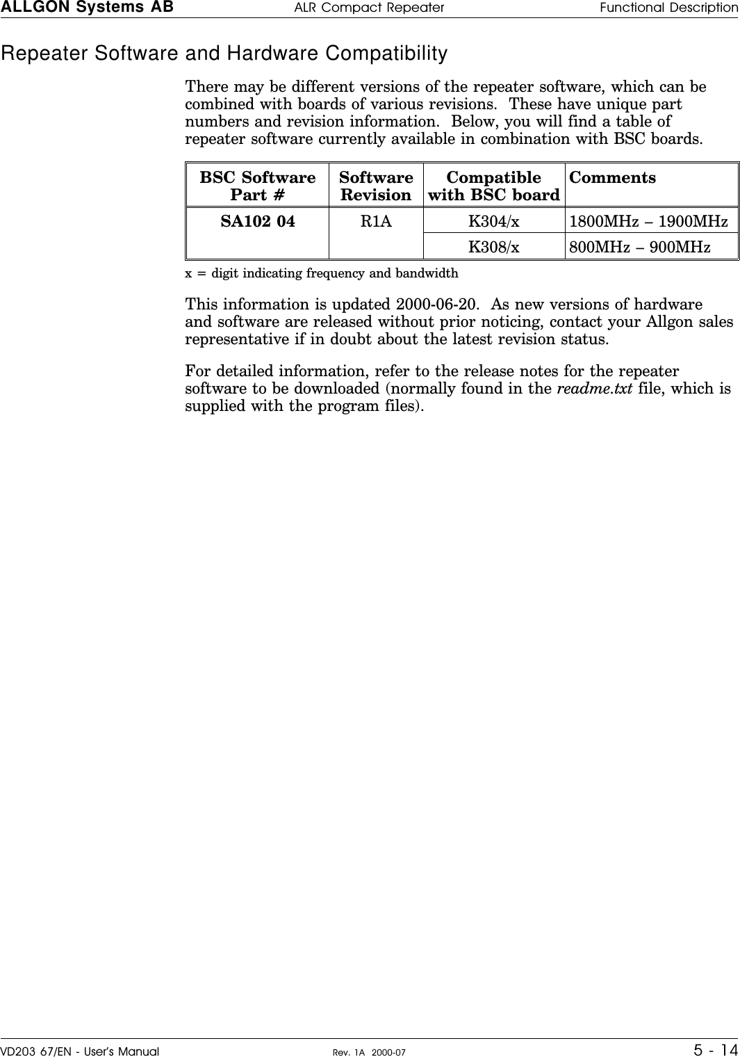
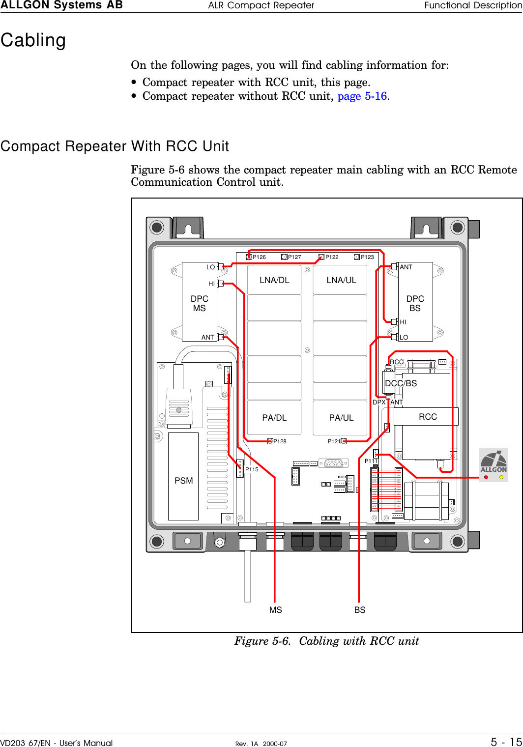
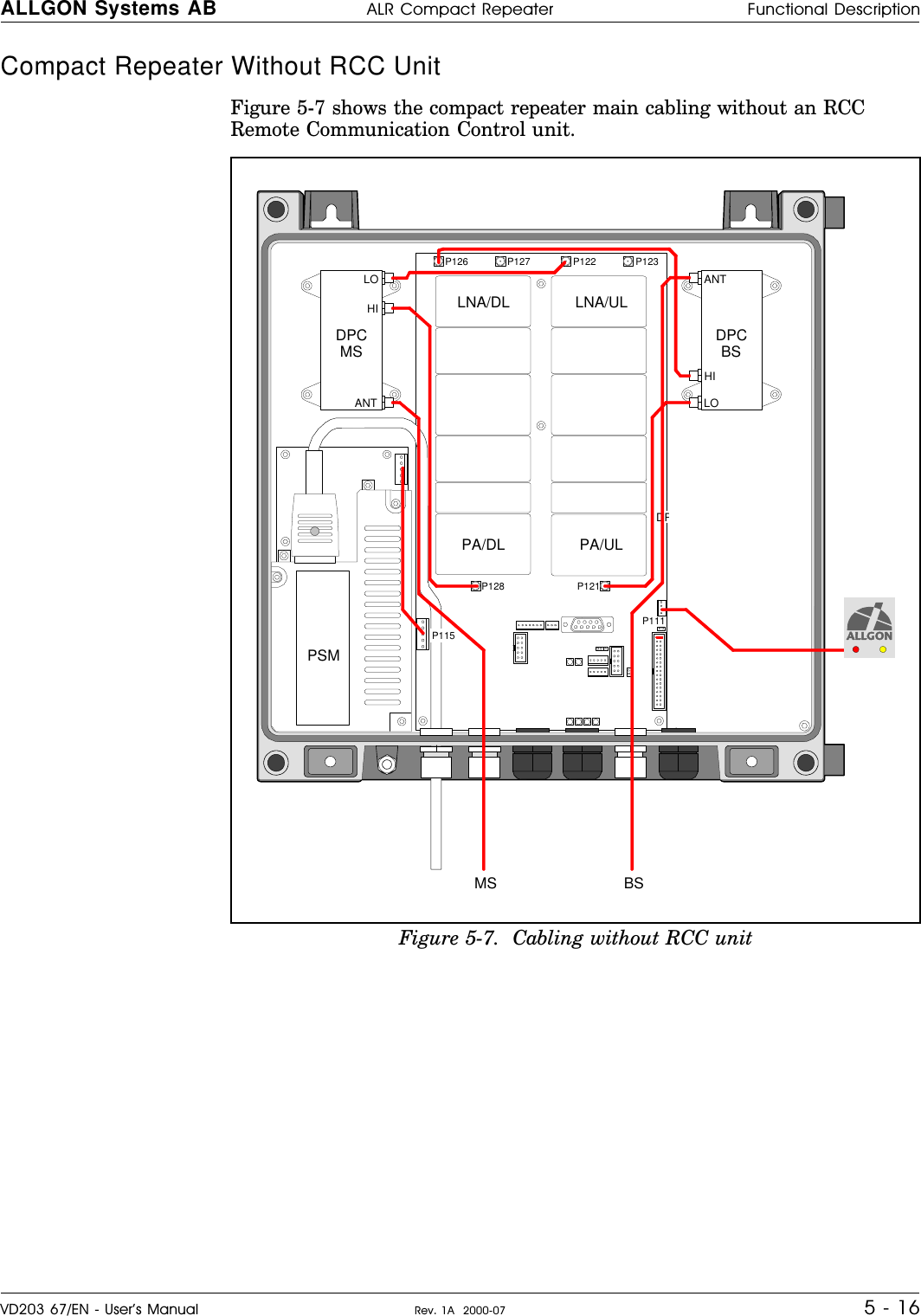
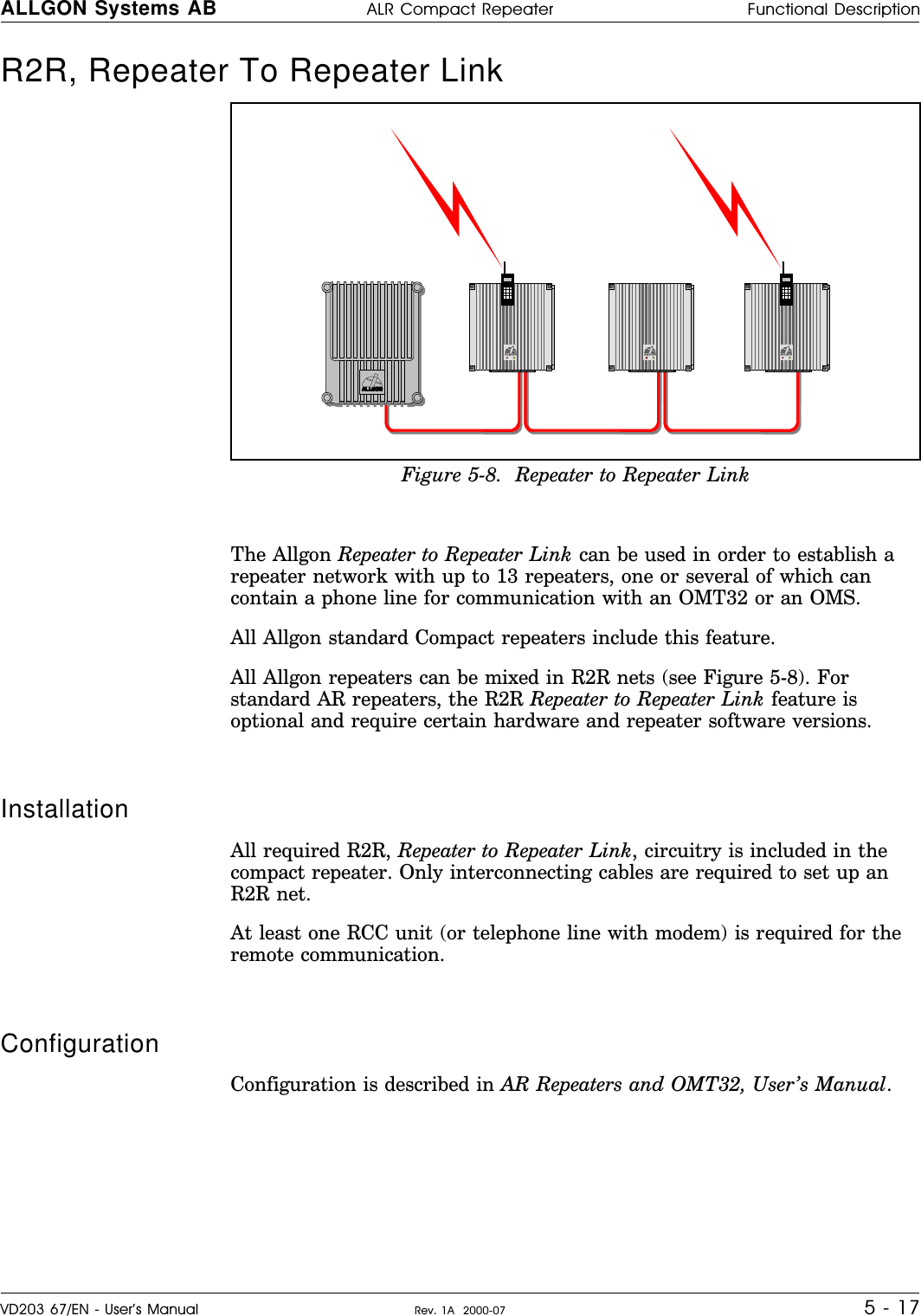
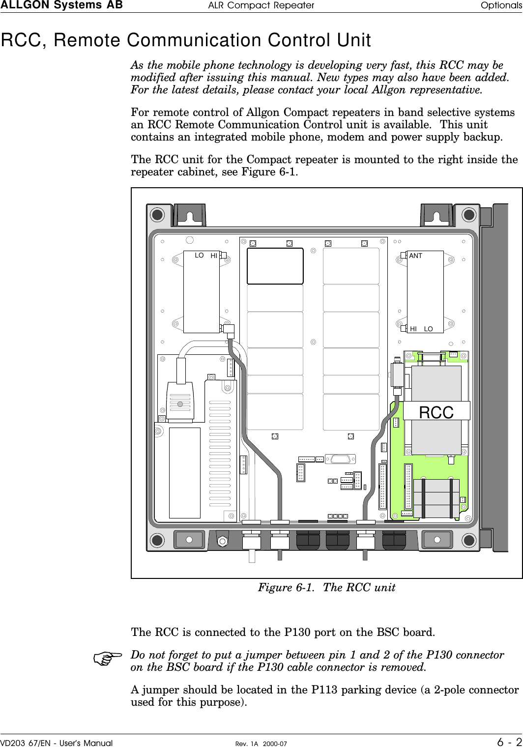
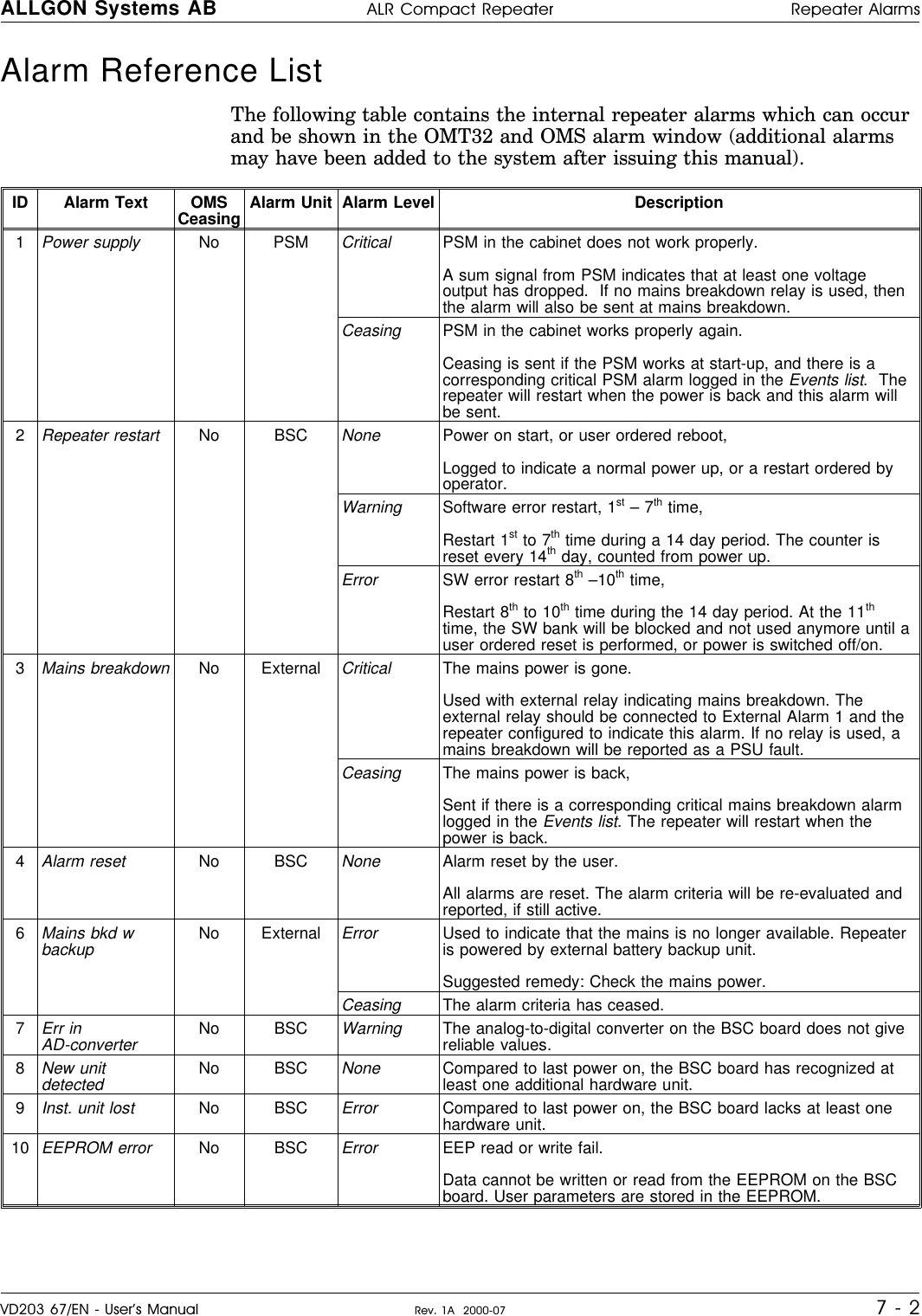
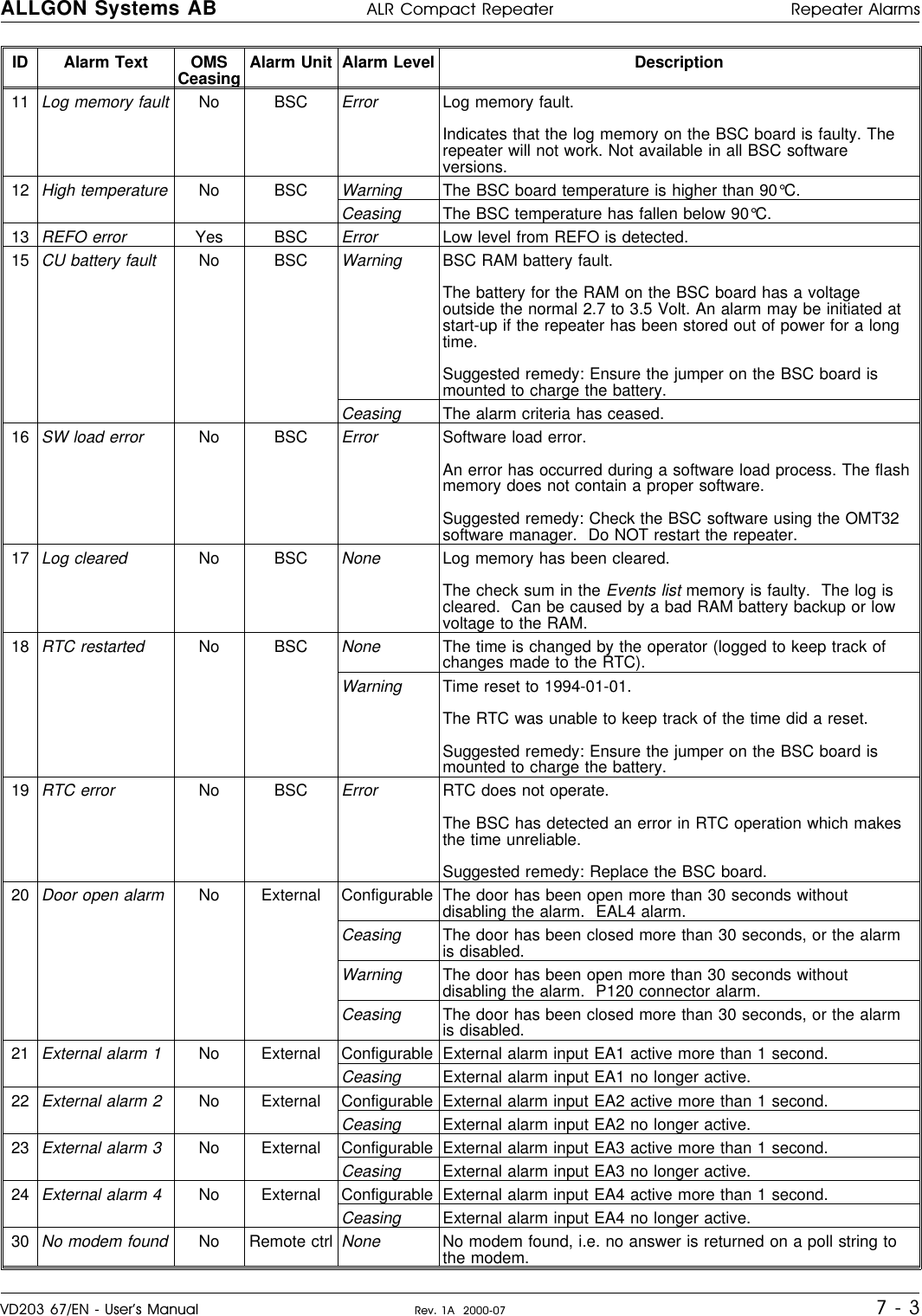
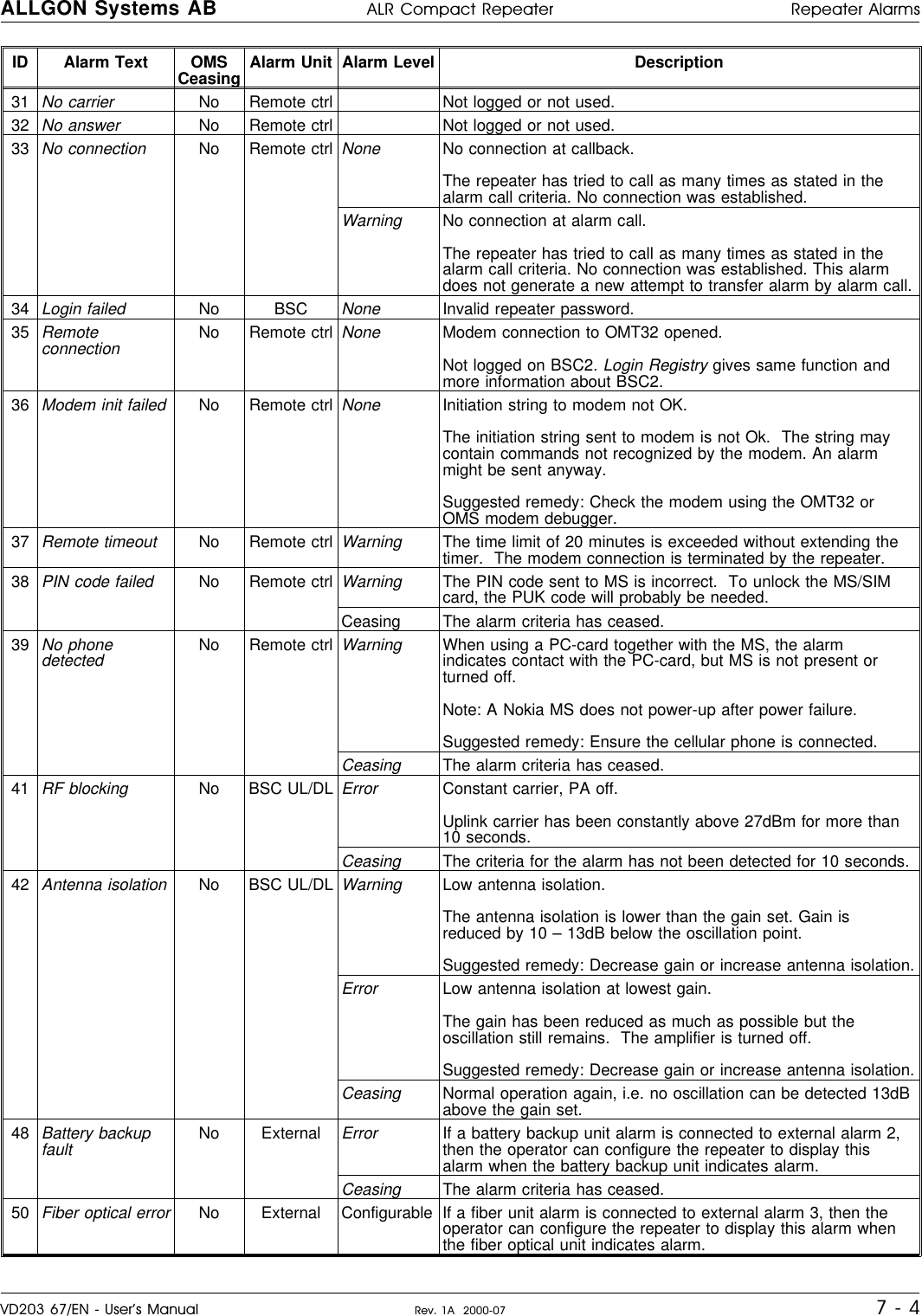
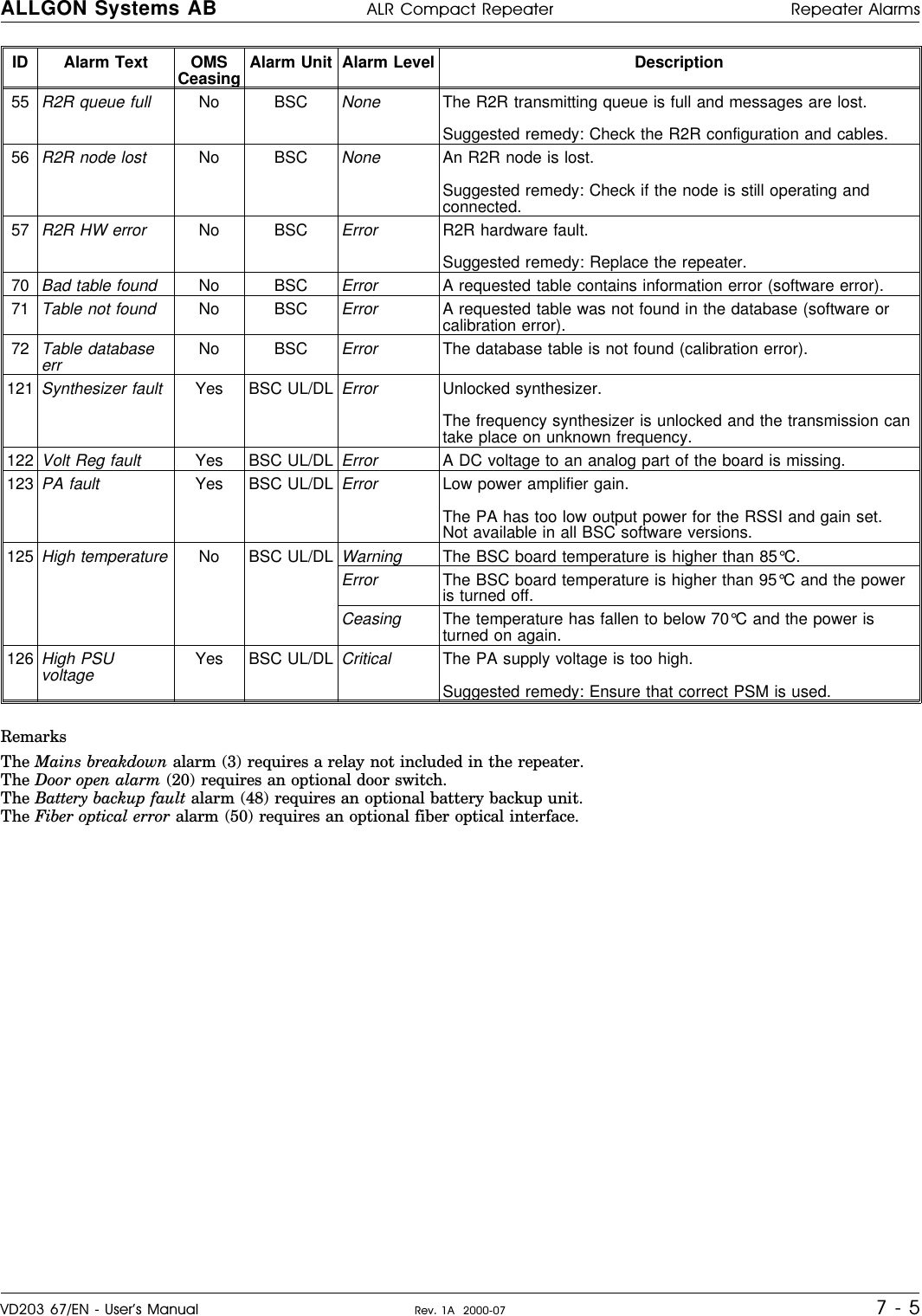
users manual