Powerwave Technologies AR3430 Repeater User Manual Ventura 01EM00CF CHP
Powerwave Technologies Repeater Ventura 01EM00CF CHP
Contents
- 1. User manual
- 2. User Manual part 2
User manual
User’s Manual
AR Repeaters
VD203 66/EN – English


User’s Manual
AR Repeaters
Channel Selective and Band Selective Repeaters
–
English
LGP Allgon AB H|H#H

This document describes installation, commissioning and the design of the LGP Allgon AR Repeaters.
Communication between LGP Allgon AR repeaters and operators is carried out either by using LGP Allgon OMT32
(Operation and Maintenance Terminal), or LGP Allgon OMS (Operation and Maintenance System). OMT32 is described
in the OMT32, User’s Manual. OMS is described in the Advanced Repeater OMS, User’s Manual.
Hardware and software mentioned in this document are subjected to continuous development and improvement.
Consequently, there may be minor discrepancies between the information in the document and the performance and
design of the product. Specifications, dimensions and other statements mentioned in this document are subject to change
without notice.
Federal Communications Commission (FCC)
This equipment has been tested and found to comply with the limits for a Class A digital device, pursuant to part 15 of
the FCC Rules. These limits are designed to provide reasonable protection against harmful interference when the
equipment is operated in a commercial environment. This equipment generates, uses, and can radiate radio frequency
energy and, if not installed and used in accordance with the instruction manual, may cause harmful interference to radio
communications. Operation of this equipment in a residential area is likely to cause harmful interference in which case
the user will be required to correct the interference at his own expense.
LGP Allgon and its suppliers shall not be liable for any damages related to the software or hardware, or for any other damages whatsoever caused of the use
of or inability to use any LGP Allgon product. This is applicable even if LGP Allgon has been advised of the damage risk. Under any circumstances, LGP
Allgon’s entire liability shall be limited to replace such defective software or hardware which was originally purchased from LGP Allgon.
Teflon is a registered trademark of Du Pont. Other trademarks mentioned in this document are trademarks or registered trademarks of their respective
owners.
This document is produced by El, Tele & Maskin Ingenjörsfirma AB, Huddinge, Sweden.
Printed in Sweden.
LGP Allgon AB, SE-187 80 Täby, Sweden
Phone: +46 8 540 822 00 – Fax: +46 8 540 834 80 – Internet: www.lgpallgon.com
This document or parts of it may not be reproduced without the written permission of LGP Allgon AB.
Infringements will be prosecuted. All rights reserved.
Copyright © LGP Allgon AB, Sweden, 1994 – 2004.
H|H#H LGP Allgon AB

Contents
,,H¨c#cro ¨ccc
u#QH« uau
#ocoXcXo ua¤
¦j#oª|r¦HrQ#?c#cro ua
H|H#HoHoo# ua
o#ff#cro#o?#coHo#o6HrQoHoo#«Hj ua
#?c#croª|r¦H uaV
#?c#cro#QH«c#o6H uaV
#c6fH6c6c« ua
¤or?¦6cro ¤au
H|H#H¨H¨cH© ¤a¤
coXH|H#H ¤aV
`#?H? H# ¤aS
|rHo# ¤a
c,H|c6 cc,¦cro H ¤a
o#ff#cro au
ccoX`HH|H#H au
¦o`coH au
`HfH au
¦?rro#ff#cro#o?H¨c6Hcjc#cro au
cjHocro#o?HcX` a¤
r¦ocoX aV
rooH6cro a
rooH6coXH|H#H aI
rooH6coXcX`r©HrH|H#H ap
rooH6coX au®
rooH6coX auu
rooH6coX au¤
ªHo#f f#j au
rr|Hof#j au
¤<H|H#HrH|H#Hcoe auV
¤<c,Hrc,Hcoe auV
#coH#e?r©oHf#« auS
coc`coX`Ho#ff#cro au
o#ffcoX¤VrfrVIrfr©H¦||f«oc au
VrjjccrocoX Vau
#coX`HH|H#H Va¤
o?c6#rco`H#,coH Va
o?c6#rro`HH|H#Hro VaV
H#¦coX`H¦|¦cXo#fH¨Hf VaS
rf#XH¦||f«H|rco Va
H|H#HroQcX¦#cro Va
LGP Allgon AB H|H#H

S¦o6cro#fH6c|cro Sau
HoH#f H6c|cro Sau
H|H#H«|H Sa¤
`#ooHfHfH6c¨HH|H#H Sa¤
`#ooHfHfH6c¨HH|H#H Sa¤
`#ooHfHfH6c¨HcX`r©HH|H#H Sa¤
#o?HfH6c¨HH|H#H Sa¤
rj,coH?H|H#H Sa
<#H#cro#Hoc Sa
<H|H#H#Hoc Sa
<c,H|c6H|H#H Sa
H|H#HHcXo SaV
¦,oc¨H¨cH© SaV
¦,occo#`#ooHfHfH6c¨HH|H#H SaI
¦,occo#`#ooHfHfH6c¨HH|H#H Sap
¦,occo#`#ooHfHfH6c¨HcX`r©HH|H#H Sau®
¦,occo##o?HfH6c¨HH|H#H Sauu
¦,occo#rj,coH?H|H#H Sau¤
¦,occo# Sau
¦,occo#o SauV
¦,occo# SauS
fr6ec#X#j Sau
r©ofcoecXo#f#` Sau
|fcoecXo#f#` Sau
`#ooHfHfH6c¨HH|H#H SauI
`#ooHfHfH6c¨HH|H#H Sa¤®
#o?HfH6c¨HH|H#H Sa¤¤
Sa¤V
Sa¤
Sa¤I
Sa®
Sa®
¤ Sa®
¤ Sau
f#j Sau
H|H#HH¦| Sau
r#?#o?ocH6c|cro Sa¤
L`#ooHfj|fcQcHr#? Sa
&L`#ooHfHfH6c¨Hr#? SaV
LrrHj|fcQcHQrcX`r©H SaS
& L#o?HfH6c¨Hr#? Sa
Lcc,¦cror#? Sa
Lrorfocr#? Sap
LH#¦HjHoH6Hc¨Hr#? SaV®
LcH6cro#fr¦|fH SaV¤
Lr©rcHj|fcQcH SaV
L¦|fHª cfH SaVV
L c,H |c6oc SaVS
Lc,H|c6r?Hr#? SaV
Lc,H|c6#o6Hc¨Hr#? SaS®
H|H#H LGP Allgon AB

rooH6cror SaS¤
¤¦ªcfc#«r SaS
u r SaS
¤r?Hjr SaSV
f#jr SaSV
VH|H#HrH|H#Hcoer SaS
#,fcoX SaS
`#ooHfHfH6c¨HH|H#H<©r`#ooHf SaSI
`#ooHfHfH6c¨HH|H#H<r¦`#ooHf SaSp
`#ooHfHfH6c¨HH|H#Hc` <©r`#ooHf Sa®
`#ooHfHfH6c¨HH|H#H<©r`#ooHf Sau
`#ooHfHfH6c¨HcX`r©HH|H#H<©r`#ooHfSa¤
#o?HfH6c¨HH|H#H Sa
SaV
SaS
Sa
H|H#HrQ©#H#o?#?©#Hrj|#c,cfc« Sa
|cro#f au
<HjrHrorfocQrp®®uI®®up®® a¤
<HjrHrorfoc©c`r?Hj aV
<HjrHrjj¦oc6#crororfoc a
¤<H|H#HrH|H#Hcoe a
¤H¦cHjHo a
o#ff#cro aI
roQcX¦#cro aI
¤ 66H aI
#QQc6#cc6 ap
#H«#6e¦| ap
uoHoo##,fHrooH6r ap
<|H#cro#o?#coHo#o6H«Hj ap
H|H#Hf#j au
f#jHQHHo6Hc a¤
o?Hª au
¦Hcroo#cH au
LGP Allgon AB H|H#H

Figures
cX¦Huau#QH«?c#o6Hr#6c¨H#oHoo# uaS
cX¦H¤auffXroH|H#H ¤au
cX¦H¤a¤H|H#H6r¨H#XHrQ`#?H?#H# ¤aS
cX¦H¤aH|H#Hco|r#Ho# ¤a
cX¦H¤aVoH#o?Qr¦co|##ffHf ¤a
cX¦H¤aSoH#o?Qr¦coHc#f ¤a
cX¦HauH|H#H?cjHocro a¤
cX¦Ha¤cX`|r©HH|H#H a¤
cX¦Ha#6`coX`H,#6eHr#©#ff aV
cX¦HaV#6`coX`H,#6eHr#|rfH aS
cX¦HaS#6`coX`H,#6eHr#j# aS
cX¦Ha#6`coX`HH|H#Hr`H,#6eH a
cX¦HarooH6coXH|H#H aI
cX¦HaIrooH6coX`cX`|r©HH|H#H ap
cX¦HaprooH6coX au®
cX¦Hau®rooH6coX auu
cX¦HauurooH6coX au¤
cX¦Hau¤ªHo#f#f#j6rooH6cro au
cX¦Hau¤6rooH6cro auV
cX¦HauV#co,H#e?r©oHf#«6rooH6cro auS
cX¦HauSH|f#6coXj#co©c`¤VrVI au
cX¦HVaurooH6coX#Qrfr6#fH¦| Vau
cX¦HVa¤oHo#fco?c6#r#o?j#co©c6` Va
cX¦HVaªHo#fco?c6#r VaV
cX¦HVaVH#¦coX|rQrr¦|¦cXo#ffH¨Hf VaS
cX¦HSau¦,¦occo#H|H#H SaI
cX¦HSa¤¦,¦occo#H|H#H Sap
cX¦HSa ¦,¦occo#`cX`|r©HH|H#H Sau®
cX¦HSaV¦,¦occo#,#o?HfH6c¨HH|H#H Sauu
cX¦HSaS¦,¦occo#6rj,coH?H|H#H Sau¤
cX¦HSa¦,¦occo# Sau
cX¦HSa¦,¦occo#o SauV
cX¦HSaI¦,¦occo# SauS
cX¦HSapfr6e?c#X#j<H|H#H SauI
cX¦HSau®fr6e?c#X#j<H|H#H Sa¤®
cX¦HSauufr6e?c#X#j<,#o?HfH6c¨HH|H#H Sa¤¤
cX¦HSau¤fr6e?c#X#j< Sa¤V
cX¦HSaufr6e?c#X#j< Sa¤
cX¦HSauVfr6e?c#X#j< Sa¤I
cX¦HSauS,r#?6rooH6r#o?H|rco Sa
cX¦HSau H#¦HjHoH6Hc¨H,r#? SaV®
cX¦HSau #o??cH6cro#f 6r¦|fH SaV¤
cX¦HSauIfr©orcH#j|fcQcH SaV
cX¦HSaup<c,H|c6oc SaVS
cX¦HSa¤®<c,H|c6r?H,r#? SaV
H|H#H LGP Allgon AB

cX¦HSa¤uco?c6#r#o?|r SaV
cX¦HSa¤¤co?c6#r#o?|r SaS®
cX¦HSa¤rooH6cro|r#o?#croXr¦o? SaS¤
cX¦HSa¤V#,fcoX<¤6`#ooHfH|H#H SaSI
cX¦HSa¤S#,fcoX<V6`#ooHfH|H#H SaSp
cX¦HSa¤#,fcoX<¤6`#ooHfH|H#H©c` Sa®
cX¦HSa¤#,fcoX<¤6`#ooHfH|H#H Sau
cX¦HSa¤I#,fcoX<¤6`#ooHf`cX`|r©H Sa¤
cX¦HSa¤p#,fcoX<,#o?HfH6c¨HH|H#H Sa
cX¦HSa®#,fcoX< SaV
cX¦HSau#,fcoX< SaS
cX¦HSa¤#,fcoX< Sa
cX¦Hauap®®«|H a¤
cX¦Ha¤acªH?cHcoH«|H aS
cX¦HaH|H#HrH|H#Hcoe a
LGP Allgon AB H|H#H

Abbreviations
Abbreviations used in this manual, in the software, and in the repeaters:
AGC Automatic Gain Control.
ALI Alarm Interface board.
AMPS Advanced Mobile Phone Service.
BCCH Broadcast Control Channel (GSM broadcast channel time slot).
BMU Base station Master Unit.
BA Booster Amplifier.
BS Base Station.
BSA Band Selective Amplifier board.
BSel Band Selective.
BTS Base Transceiver Station.
CDMA Code Division Multiple Access.
CHA Channel Amplifier board.
CMB Combiner unit.
CSA CDMA/WCDMA Segment Amplifier board.
CSel Channel Selective.
CU Control Unit board.
CW Continuous Wave.
DAMPS Digital Advanced Mobile Phone Service.
DC Directional Coupler.
DCS Digital Communication System (same as PCN).
DIA Distribution board.
DL Downlink signal direction (from base station, via repeater, to mobile station).
DPX Duplex filter.
EEPROM Electrical Erasable Programmable Read Only Memory.
EGSM Extended Global System for Mobile communication.
ETACS Extended Total Access Communication System.
ETSI European Telecommunications Standard Institute.
F2F Fiber to Fiber Link.
FON Fiber Optic Node board.
FOR Fiber Optic Repeater.
FOT Fiber Optic Transciever.
FOU Fiber Optic Unit.
GSM Global System for Mobile communication.
HW Hardware.
LED Light Emitting Diode.
LNA Low Noise Amplifier, uplink and downlink.
MRX Measurement Receiver board.
MS Mobile Station.
MSC Mobile Switching Center.
NMT Nordic Mobile Telephone system.
OMS Operation and Maintenance System.
OMT32 Operation and Maintenance Terminal.
OSP Optical Splitter.
PA Power Amplifier board.
PCN Personal Communication Network (same as DCS).
PCS Personal Communication System.
PSTN Public Switched Telephone Network.
PSU Power Supply Unit.
PTFE Polytetrafluoro Ethylene (Teflon).
R2R Repeater to Repeater Link.
RCC Remote Communication Control unit.
H|H#H LGP Allgon AB

RCU Remote Control Unit.
RF Radio Frequency.
RIA Repeater to Repeater Interface Adapter board.
RMU Repeater Master Unit.
RSSI Received Signal Strength Indication.
RTC Real Time Clock.
SW Software.
TACS Total Access Communication System.
TDMA Time Division Multiple Access.
UL Uplink signal direction (from mobile station via repeater to base station).
UPS Uninterruptible Power Supply.
WCDMA Wideband Code Division Multiple Access.
WDM Wavelength Division Multiplexer.
LGP Allgon AB H|H#H

H|H#H LGP Allgon AB
LGP Allgon %66ITIEXIVW Safety
1 - 1
1. Safety
3X^RS]MRKZ^O\^ROaY\Nt\OZOK^O\tSXMV_NO]KVV61:+VVQYX\OZOK^SXQ_XS^]
]_MRK]\OZOK^O\]R_L]KXN\KNSYROKN]
3^S]XOMO]]K\c^RK^KXcZO\]YXXOVSX`YV`ONSXSX]^KVVK^SYXYZO\K^SYXY\
]O\`SMOYP_XS^]SXMV_NONSXKX61:+VVQYX\OZOK^O\]c]^OW_XNO\]^KXNKXN
PYVVYa^ROLOVYaZYSX^]
w>RO61:+VVQYX\OZOK^O\]K\ONO]SQXON^Y\OMOS`OKXNKWZVSPc]SQXKV]
P\YWYXOY\WY\OLK]O]^K^SYX]KXN\O^\KX]WS^^RO]SQXKV]^YYXOY\WY\O
WYLSVO]^K^SYX]+XNKV]Y^YKM^^ROY^RO\aKc\Y_XN^RK^S]^Y\OMOS`O
]SQXKV]P\YWYXOY\WY\OWYLSVO]^K^SYX]KWZVSPcKXN\O^\KX]WS^^RO
]SQXKV]^Y^ROLK]O]^K^SYX]61:+VVQYX\OZOK^O\]c]^OW]W_]^LO_]ON
ObMV_]S`OVcPY\^RS]Z_\ZY]OKXNXY^RSXQOV]O
w?XS^]]_ZZVSONP\YW^ROWKSX]W_]^LOMYXXOM^ON^YQ\Y_XNONY_^VO^]KXN
SXMYXPY\WS^caS^R^ROVYMKVZ\O]M\SZ^SYX]
w:YaO\]_ZZVc_XS^]]_ZZVSONP\YW^ROWKSX]MYX^KSXNKXQO\Y_]`YV^KQO
^RK^MKXMK_]OOVOM^\SM]RYMU.S]MYXXOM^^ROWKSX]Z\SY\^YKXcaY\USX
]_MRK_XS^6YMKV\OQ_VK^SYX]K\O^YLOPYVVYaONaROX]O\`SMSXQ]_MR
_XS^]
+_^RY\SdON]O\`SMOZO\]YXXOVYXVcK\OKVVYaON^Y]O\`SMO_XS^]aRSVO^RO
WKSX]S]MYXXOM^ON
w>RO\OZOK^O\MY`O\W_]^LO]OM_\ONSXYZOXONZY]S^SYXPY\SX]^KXMOLc
^cSXQS^_ZK^Y_^NYY\\OZOK^O\aY\U9^RO\aS]O^ROMY`O\MKXLOMVY]ON
Lc^ROaSXNKXNMK_]OcY_\PSXQO\]QO^^SXQZSXMRONY\cY_\ROKNLOSXQRS^
wAROXaY\USXQYXK\OZOK^O\YXRSQRQ\Y_XNPY\SX]^KXMOYXKWK]^Y\
ZYVOLOMK\OP_VXY^^YN\YZZK\^]Y\^ROOX^S\O\OZOK^O\0KVVSXQZK\^]MKX
MK_]O]O\SY_]ZO\]YXKVSXT_\c
w+VV<0^\KX]WS^^SXQ_XS^]SXMV_NSXQ\OZOK^O\]aSVVQOXO\K^O\KNSY]SQXKV]
KXN^RO\OLcQS`O\S]O^YOVOM^\YWKQXO^SMPSOVN]^RK^WKcLORKdK\NY_]^Y
^ROROKV^RYPKXcZO\]YXaRYS]Ob^OX]S`OVcObZY]ONMVY]O^YKXKX^OXXK
=OO^RO2_WKX/bZY]_\OYP<0<KNSK^SYX]OM^SYXYXZKQO
Beryllium oxide
w,O\cVVS_WYbSNO,O9WKcLOMYX^KSXONSXZYaO\NO`SMO]PY\SX]^KXMOSX
N_WWcVYKN]SXNS\OM^SYXKVMY_ZVO\].--SXMYWLSXO\_XS^]-7,KXN
SXK^^OX_K^Y\]YX^RO098LYK\N,O\cVVS_WYbSNOS]ZYS]YXY_]SPZ\O]OX^
K]N_]^Y\]WYUO^RK^MKXLOSXRKVON
.YXY^PSVOQ\SXNWKMRSXOY\^\OK^^RO]OZK\^]aS^RKMSN
Hydrogen fluoride
w-YKbSKVMKLVO]_]ONSXWKXc61:+VVQYX]c]^OW]RK`O^ROSX]_VK^SYX
WKNOYP:>0/ZYVc^O^\KPV_Y\YO^RcVOXO^RK^QS`O]YPP]WKVVKWY_X^]YP
RcN\YQOXPV_Y\SNOaROXROK^ON2cN\YQOXPV_Y\SNOS]ZYS]YXY_].YXY^
_]OROK^SXQ^YYV]aROX]^\SZZSXQYPPMYKbSKVMKLVOSX]_VK^SYX
8YZK\^SM_VK\WOK]_\O]K\O^YLO^KUOXSXMK]OYPPS\OLOMK_]O^ROOWS^^ON
MYXMOX^\K^SYXYPRcN\YQOXPV_Y\SNOS]`O\cVYa
Safety %66ITIEXIVW LGP Allgon
1 - 2
w+VS^RS_WLK^^O\cS]ZO\WKXOX^VcWY_X^ONSX\OZOK^O\-?_XS^]KXNSX
098KXN9-7_XS^]._O^Y^RO\S]UYPObZVY]SYX^RS]LK^^O\cW_]^YXVc
LO\OWY`ONP\YW^ROLYK\NLcKX61:+VVQYXK_^RY\SdON]O\`SMO
^OMRXSMSKX
w8S-NLK^^O\SO]K\OWY_X^ONYX^RO098_XS^>RO]OLK^^O\SO]MYX^KSX
OX`S\YXWOX^KVZYS]YXY_]]_L]^KXMO]3P\OZVKMON^ROYVNLK^^O\SO]]RY_VN
LO^KUOXMK\OYPK]]^K^ONSX^ROVYMKVZ\O]M\SZ^SYX]
w>RO098_XS^MYX^KSX]KMVK]] 333LVK]O\^\KX]WS^^O\^RK^OWS^] xWA
SX`S]SLVOVK]O\\KNSK^SYXN_\SXQYZO\K^SYX+`YSNNS\OM^ObZY]_\OP\YW
_XMYXXOM^ONVK]O\^\KX]WS^^O\Y\PSLO\MY\NK]PYVVYa]$
x .YXY^ZYaO\_Z^RO098_XS^SPKPSLO\MKLVOS]XY^K^^KMRON^Y^RO
PSLO\Y_^Z_^?6ZY\^XOS^RO\SPKPSLO\MKLVOS]K^^KMRON^Y^ROZY\^
L_^_XK^^KMRONSX^ROY^RO\OXN
x 8O`O\VYYUSX^ROOXNYPKPSLO\MKLVO>ROXWKXNXWVK]O\
VSQR^S]XY^`S]SLVO]YXY]SQXKVSNOX^SPSMK^SYXMKXLOWKNOKXcaKc
?]OKVaKc]KXSX]^\_WOX^]_MRK]KZYaO\WO^O\^YNO^OM^]SQXKVSXQ
x 8O`O\_]OKXcUSXNYPWKQXSPcSXQNO`SMO]^RK^MKXPYM_]^ROVK]O\
VSQR^^YKX_XKSNONOcO
Warning Signs
>ROPYVVYaSXQaK\XSXQ]SQX]W_]^LOYL]O\`ONKXNLOUOZ^MVOKXKXN
\OKNKLVO
,O\cVVS_WYbSNO
>RS]aK\XSXQ]SQXS]KZZVSONYXLYK\N]KXN_XS^]aRSMRMYX^KSXLO\cVVS_W
YbSNOZK\^]
>RS]aK\XSXQ]SQXS]KZZVSONK^^ROLY^^YWSX]SNO^ROMKLSXO^LOVYa^RO
ZYaO\]_ZZVc_XS^
>ROZ\O`SY_]]OM^SYXNO^KSV]ZK\^]MYX^KSXSXQLO\cVVS_WYbSNOKXNRYa^Y
K`YSNNKXQO\Y_]NOKVSXQaS^R^RO]OZK\^]
Beryllium
oxide
hazard
BERYLLIUM OXIDE
(Toxic)
used in equipment
see instruction book

LGP Allgon %66ITIEXIVW Safety
1 - 3
Human Exposure of RF Radiation
>RS]]OM^SYXMYX^KSX]KPOaaY\N]KLY_^\OZOK^O\KX^OXXK]KXNZ\O]M\SZ^SYX]
PY\SX]^KVVK^YXKXNWKSX^OXKXMOYPKX^OXXK]c]^OW]+V]YS^NO]M\SLO]RYa
^YMKVM_VK^O]KPO^cNS]^KXMO]XOONONPY\<0\KNSK^SYXK^NSPPO\OX^KX^OXXK
ZYaO\KXNP\O[_OXMSO]
Repeater Antennas
>YLOKLVO^Y\OMOS`OKXN^\KX]WS^]SQXKV]K]NO]M\SLONSX^ROPS\]^L_VVO^ON
ZK\KQ\KZRYXZKQO K\OZOK^O\S]MYXXOM^ON^YKNYXY\KX^OXXKNS\OM^ON
^YaK\N]^ROLK]O]^K^SYXKXNK]O\`SMOKX^OXXKNS\OM^ON^YaK\N]^RO
MY`O\KQOK\OK+PSLO\YZ^SMMKLVOP\YW^ROLK]O]^K^SYXWSQR^RYaO`O\LO
]_L]^S^_^ONPY\^RONYXY\KX^OXXK
Installation and Maintenance of Antenna Systems
3X]^KVVK^SYXKXNWKSX^OXKXMOYPKVV\OZOK^O\KX^OXXK]c]^OW]W_]^LO
ZO\PY\WONaS^R\O]ZOM^^Y^RO\KNSK^SYXObZY]_\OVSWS^]PY\Z_LVSMK\OK]
>ROKX^OXXK\KNSK^SYXVO`OVS]KPPOM^ONLc^RO\OZOK^O\Y_^Z_^ZYaO\^RO
KX^OXXKQKSXKXNLc^\KX]WS]]SYXNO`SMO]]_MRK]MKLVO]MYXXOM^Y\]
]ZVS^^O\]KXNPOONO\]
2K`OKV]YSXWSXN^RK^^RO]c]^OWWSXSW_WMY_ZVSXQVY]]^cZSMKVLO^aOOX
N,KXNN,S]NO^O\WSXONLcK]^KXNK\NaS^R^ROZ_\ZY]O^YZ\Y^OM^
LK]O]^K^SYX]P\YWXYS]OKXNY^RO\ZO\PY\WKXMON\YZZSXQOPPOM^]

Safety %66ITIEXIVW LGP Allgon
1 - 4
Radiation Exposure
A29AY\VN2OKV^R9\QKXSdK^SYXKXN3-83<:3X^O\XK^SYXKV-YWWS]]SYX
YX8YX3YXS]SXQ<KNSK^SYX:\Y^OM^SYXRK`ONO^O\WSXON\OMYWWOXNK^SYX]
PY\\KNSK^SYXObZY]_\O
3-83<:\OMYWWOXN]XY^^YObMOON^ROPYVVYaSXQ\KNSK^SYXZYaO\PY\Z_LVSM
ObZY]_\O$
0\O[_OXMc <KNSK^SYXZYaO\
#72d AW
"72d #AW
72d AW
0Y\KX^OXXK]VK\QO\^RKXMW^ROWKbSW_W\KNSK^SYXZYaO\MKXLO
MKVM_VK^ONLc_]SXQ^ROPYVVYaSXQPY\W_VK$
aRO\O
= '<KNSK^SYXZYaO\SXAW
: '9_^Z_^ZYaO\SXA
\ '.S]^KXMOLO^aOOXKX^OXXKKXNR_WKXSXWO^O\
>Y^KMUVO^ROaY\]^MK]O]_MMO]]P_VVc^ROMKVM_VK^SYXNYO]XY^MYX]SNO\
]c]^OWZYaO\\ON_MSXQKM^SYX]]_MRK]ZYaO\MYX^\YVKXN.>B
0SQ_\O ]RYa]^RO]KPO^cNS]^KXMO^YKXKX^OXXKN_O^Y^RO<0\KNSK^SYX
>RONS]^KXMOS]NOZOXNSXQYX^ROKX^OXXKY_^Z_^ZYaO\KXNP\O[_OXMc
aRSMRS]SVV_]^\K^ONaS^R^aYQ\KZR]SX^ROPSQ_\O
9XOYP^ROQ\KZR]KZZVSO]^YAW #72dKXN^ROY^RO\^Y#AW
"72dY\AW 72d
>RO]KPO^cNS]^KXMO\KXQOSX0SQ_\O S]^Y WO^O\^RK^MY`O\]KX
KX^OXXKZYaO\\KXQOYPN,W^YN,WA^YA
Radiation Safety Distances
>RS]]OM^SYXSVV_]^\K^O]^RO]KPO^cNS]^KXMO]^Y^ROKX^OXXK]PY\]YWO^cZSMKV
\OZOK^O\MYXPSQ_\K^SYX]
9_^NYY\1=7#72d
>RO]KPO^cNS]^KXMOMKXLO\OKN^Y! WO^O\SX0SQ_\O K]^ROWKbSW_W
\KNSK^SYXZYaO\S]AWPY\#72d
SP
4πr2
××
--------------------
=
<OZOK^O\Y_^Z_^ZYaO\ N,W
0OONO\VY]] xN,
+X^OXXKQKSX !N,S
/3<: N,W
LGP Allgon %66ITIEXIVW Safety
1 - 5
0SQ_\O=KPO^cNS]^KXMO^YKM^S`OKX^OXXK
3XNYY\1=7#72d
>RO]KPO^cNS]^KXMOMKXLO\OKN^Y WO^O\PY\AW#72d
9_^NYY\?7>==^KXNK\N2SQR:YaO\
>RO]KPO^cNS]^KXMOMKXLO\OKN^Y# WO^O\PY\AW72d
3XNYY\?7>=
>RO]KPO^cNS]^KXMOMKXLO\OKN^Y WO^O\PY\AW72d
10
15
20
25
30
35
40
0 0.1 0.2 0.3 0.4 0.5 0.6 0.7 0.8 0.9 1.0
45
50
1.1 1.2 1.3 1.4
0.01
0.03
0.1
0.3
1.0
3.2
10.0
31.6
100
4.5W/m2 (900MHz)
9W/m2 (1800MHz)
10W/m2 (2100MHz)
Safety distance to antenna in meter
Antenna output power in dBm
Antenna output power in W
<OZOK^O\Y_^Z_^ZYaO\ N,W
0OONO\VY]] xN,
+X^OXXKQKSX N,S
/3<: "N,W
<OZOK^O\Y_^Z_^ZYaO\ "N,W
0OONO\VY]] xN,
+X^OXXKQKSX !N,S
/3<: N,W
<OZOK^O\Y_^Z_^ZYaO\ N,W
0OONO\VY]] xN,
+X^OXXKQKSX N,S
/3<: N,W

Safety %66ITIEXIVW LGP Allgon
1 - 6
Static Electricity
=^K^SMOVOM^\SMS^cWOKX]XY\S]UYPZO\]YXKVSXT_\cL_^S^MKX]O`O\OVcNKWKQO
O]]OX^SKVZK\^]YP^ROO[_SZWOX^SPXY^RKXNVONMK\OP_VVc
:K\^]YX^ROZ\SX^ONMS\M_S^LYK\N]K]aOVVK]Y^RO\ZK\^]SX^ROO[_SZWOX^
K\O]OX]S^S`O^YOVOM^\Y]^K^SMNS]MRK\QO
8O`O\^Y_MR^ROZ\SX^ONMS\M_S^LYK\N]Y\_XSX]_VK^ONMYXN_M^Y\
]_\PKMO]_XVO]]KL]YV_^OVcXOMO]]K\c
3PcY_W_]^RKXNVO^ROZ\SX^ONMS\M_S^LYK\N]Y\_XSX]_VK^ONMYXN_M^Y\
]_\PKMO]_]O/=.Z\Y^OM^S`OO[_SZWOX^Y\PS\]^^Y_MR^ROMRK]]S]aS^RcY_\
RKXNKXN^ROXNYXY^WY`OcY_\POO^YX^ROPVYY\
8O`O\VO^cY_\MVY^RO]^Y_MRZ\SX^ONMS\M_S^LYK\N]Y\_XSX]_VK^ONMYXN_M^Y\
]_\PKMO]
+VaKc]]^Y\OZ\SX^ONMS\M_S^LYK\N]SX/=.]KPOLKQ]
2. Introduction
LGP Allgon AR repeaters are used to fill out uncovered areas in cellular
mobile systems, such as base station fringe areas, road tunnels, business
and industrial buildings, etc.
An AR repeater receives signals from a base station, amplifies and
retransmits the signals to mobile stations. Also it receives, amplifies and
retransmits signals in the opposite direction. Both directions are served
simultaneously.
To be able to receive and transmit signals in both directions, the repeater
is connected to a donor antenna directed towards the base station and to
a service antenna directed towards the area to be covered. As an
alternative to the donor antenna, the repeater can be connected to the
base station via an optic fiber cable.
Control of the repeaters is performed using a desktop or notebook loaded
with the LGP Allgon OMT32, Operation and Maintenance Terminal,
which can communicate with the repeaters either locally or remotely via
modem. Remote operation can be performed either via PSTN or a GSM
net.
To be able to control many LGP Allgon AR repeaters in common, there is
an LGP Allgon OMS, Operation and Maintenance System.
The AR repeaters are described in this manual. OMT32 is described in
the OMT32, User’s Manual.
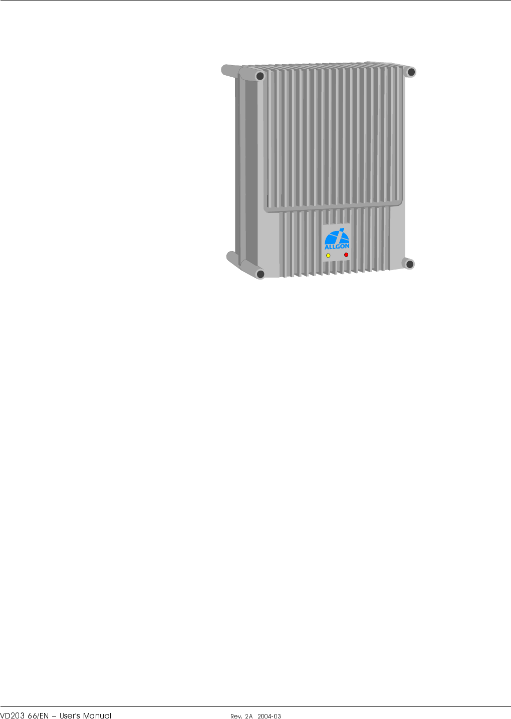
Figure 2-1. Allgon AR Repeater
LGP Allgon AB H|H#H or?¦6cro
¤au
Repeater Overview
The AR repeater family includes the following main repeater types:
•Channel selective GSM repeater.
•Channel selective CDMA/WCDMA repeater.
•Channel selective high power CDMA/WCDMA repeater.
•Band selective repeater.
•Combined repeater.
•BMU, Base station Master Unit.
•RMU, Repeater Master Unit.
•FOR, Fiber Optic Repeater.
These main repeater types are briefly described below.
In this document, the channel selective 900, 1800, and 1900 systems are
called GSM, DCS and PCS respectively, even though these systems may
have different names in other parts of the world.
Channel selective GSM repeater
This repeater is used for channel selective systems such as GSM, DCS,
PCN and PCS.
The channel selective GSM repeater has an RF port for a donor antenna
(or RF cable) and an RF port for a service antenna (or RF cable).
Channel selective CDMA/WCDMA repeaters
These repeater types are used for digital code division systems in
accordance with IS-95 or J-std-008 standard, and wideband digital code
division systems.
The channel selective CDMA/WCDMA repeaters have an RF port for a
donor antenna (or RF cable) and an RF port for a service antenna (or RF
cable).
Channel selective high power CDMA/WCDMA repeaters
These are CDMA/WCDMA repeaters equipped with a 6dB (typically) BA
(Booster Amplifier) in the downlink transmitting signal path.
The channel selective high power CDMA/WCDMA repeaters have an RF
port for a donor antenna (or RF cable) and an high power RF port for a
service antenna (or RF cable).
RF RF
ALLGON
RF RF
ALLGON
RF RF
ALLGON
or?¦6cro H|H#H LGP Allgon AB
¤a¤
Band selective repeater
This repeater type is used for analog or digital systems such as NMT,
GSM, TACS, ETACS, AMPS, DAMPS, CDMA and WCDMA.
The band selective repeater has an RF port for a donor antenna (or RF
cable) and an RF port for a service antenna (or RF cable).
Combined repeater
Some of the repeater types can be combined in the same repeater chassis
and be in operation in parallel.
The combined repeater has normally two RF ports for donor antennas (or
RF cables) and two RF ports for service antennas (or RF cables).
BMU, Base Station Master Unit
A BMU is one of the RF repeater types equipped with a FOU (Fiber Optic
Unit) that makes the repeater receive and transmit optic signals on the
service side.
The BMU has an RF port for BTS connection and up to four fiber optic
ports that can be connected to FORs.
RMU, Repeater Master Unit
An RMU is one of the RF repeater types equipped with a FOU (Fiber
Optic Unit) that makes the repeater receive and transmit optic signals on
the service side.
The RMU has an RF port for a donor antenna and up to four fiber optic
ports that can be connected to FORs.
FOR, Fiber Optic Repeater
A FOR is one of the RF repeater types equipped with a FOU that makes
the repeater receive and transmit optic signals on the donor side.
The FOR has a fiber optic donor port and an RF port for a service
antenna (or RF cable). By equipping a FOR with a splitter, another FOR
can be connected in serial.
This unit can be connected to a BMU, RMU or FOR (with splitter).
RF RF
ALLGON
RF RF
ALLGON
ALLGON
RF
ALLGON
RF
RF
ALLGON
LGP Allgon AB H|H#H or?¦6cro
¤a

Using Repeaters
In areas where the radio signal propagation is poor repeaters can be used
to fill out those areas which are not covered by the base station.
The following scenarios are examples on this:
–Sports arenas
–Fair halls
–Large shopping centres
–Road and railway tunnels
–Indoors in buildings with metal or concrete walls
Other examples where repeaters can be used to increase the coverage are:
–Shaded areas
–Fringe coverage areas
In areas where the traffic intensity is low, it is not cost efficient to install
a base station. An LGP Allgon repeater, which can be installed with a
minimum of investments, is a better solution. You save installation costs
as well as operational costs.
Examples of using repeaters
Two examples are described in the following sections. An outdoor example
in a shaded valley and an indoor example in a sports arena.
or?¦6cro H|H#H LGP Allgon AB
¤aV
Shaded Area
A valley is shaded by hills. There is a base station 5 kilometers away, but
the lowest signal strength in the valley is less than –100dBm. A mast used
for other purposes is available for a repeater installation. The mast height
is 42 meter and it is located on a hill. The scenario is illustrated in
Figure 2-2.
The donor antenna of the repeater was mounted at the top of the mast
and the service antenna was mounted at the half mast. The antenna
isolation was measured to over 100dB. The repeater was set to 80dB gain.
Measured levels: Received signal level – 60.0 dBm
Donor antenna gain 15.0 dBi
Cable loss – 5.0 dB
Repeater input level – 50.0 dBm
Adjusted repeater gain 70.0 dB
Repeater output level 20.0 dBm
Cable loss – 5.0 dB
Service antenna gain 8.0 dBi
Radiated output level 23.0 dBm
The measured result in the valley was better than –90dBm.
Donor antenna
Service antenna
Figure 2-2. Repeater coverage of shaded area
LGP Allgon AB H|H#H or?¦6cro
¤aS
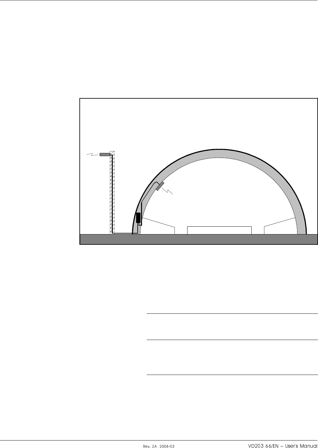
Sports Arena
A 2000 spectators sports arena with metallic roof had an indoor signal
strength too low to provide a fair service in most parts of the arena. The
nearest base station was 8 kilometers away and it was equipped with one
carrier only.
A donor antenna directed towards the base station was mounted on a
mast outside the building and a repeater was installed inside the building
with the service antenna on the arch vault. The scenario is illustrated in
Figure 2-3.
The antenna isolation was measured to over 85dB.
Measured levels: Received signal level – 80.0 dBm
Donor antenna gain 15.0 dBi
Cable loss – 5.0 dB
Repeater input level – 70.0 dBm
Adjusted repeater gain 75.0 dB
Repeater output level 5.0 dBm
Cable loss – 2.0 dB
Service antenna gain 7.0 dBi
Radiated output level 10.0 dBm
The signal strength was fair for service in the entire arena.
Service antenna
Donor antenna
Figure 2-3. Repeater in sports arena
or?¦6cro H|H#H LGP Allgon AB
¤a
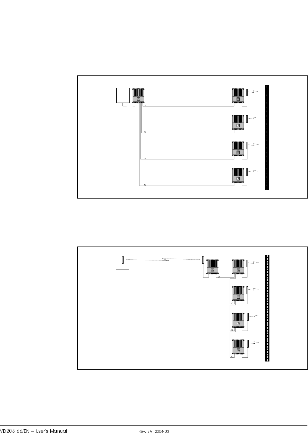
Fiber Optic Distribution Net
The following two examples illustrate a part of a road covered by means
of a BMU or an RMU and four FORs in a fiber optic distribution net.
Figure 2-4 shows a BMU fed via an RF cable from the BTS and four fiber
optic ports that feed four FORs in parallel. The BMU has to be located
very close to the BTS.
Figure 2-5 shows an RMU with a donor antenna and one fiber optic port
that feeds four FORs in serial.
By using WDMs and OSPs in the fiber optic repeaters, the optic
distribution net can be built up with a combination of serial and parallel
connections with double or single fiber communication.
BMU FOR
FOR
FOR
FOR
ALLGON
ALLGON
ALLGON
ALLGON
BTS
RF
ALLGON
Figure 2-4. One BMU and four FORs in parallel
RMU FOR
FOR
FOR
ALLGON
ALLGON
FOR
ALLGON
ALLGON
BTS
ALLGON
Figure 2-5. One RMU and four FORs in serial
LGP Allgon AB H|H#H or?¦6cro
¤a

or?¦6cro H|H#H LGP Allgon AB
¤aI

3. Installation
Before installation, read carefully Chapter 1, Safety.
Siting the Repeater
LGP Allgon repeaters are designed for outdoor usage. However, humidity
and temperature changes may have affect on the reliability. A preferable
site for the repeater is thus indoor, in a tempered and ventilated room.
Sunshine
If a repeater is placed outdoor and can be exposed to direct sunshine, it is
essential that the air can circulate around the repeater with no obstacle.
The operating temperature must not exceed +55°C. A shelter can be used
to shade the repeater from direct sunshine.
Shelter
LGP Allgon repeaters are designed with a weather proof outdoor case that
can be mounted without any kind of shelter from rain, snow or hail.
If a repeater is to be opened on the site when raining, snowing, or hailing
there must be some kind of permanent or temporary shelter. This is
applicable to gentle rainfall, snowfall or hail. Limitations for very bad
weather is found in the next section.
LGP Allgon can provide a shelter designed for these repeaters. This
shelter is shown in Figure 3-1.
Outdoor Installation and Service Limitations
Sited outdoors, the repeater must not be opened for installation or service
at bad weather, such as:
–Intense rainfall, snowfall or hail.
–Storm or high wind.
–Extremely low or high temperature.
–High humidity of the air.
LGP Allgon AB H|H#H o#ff#cro
au
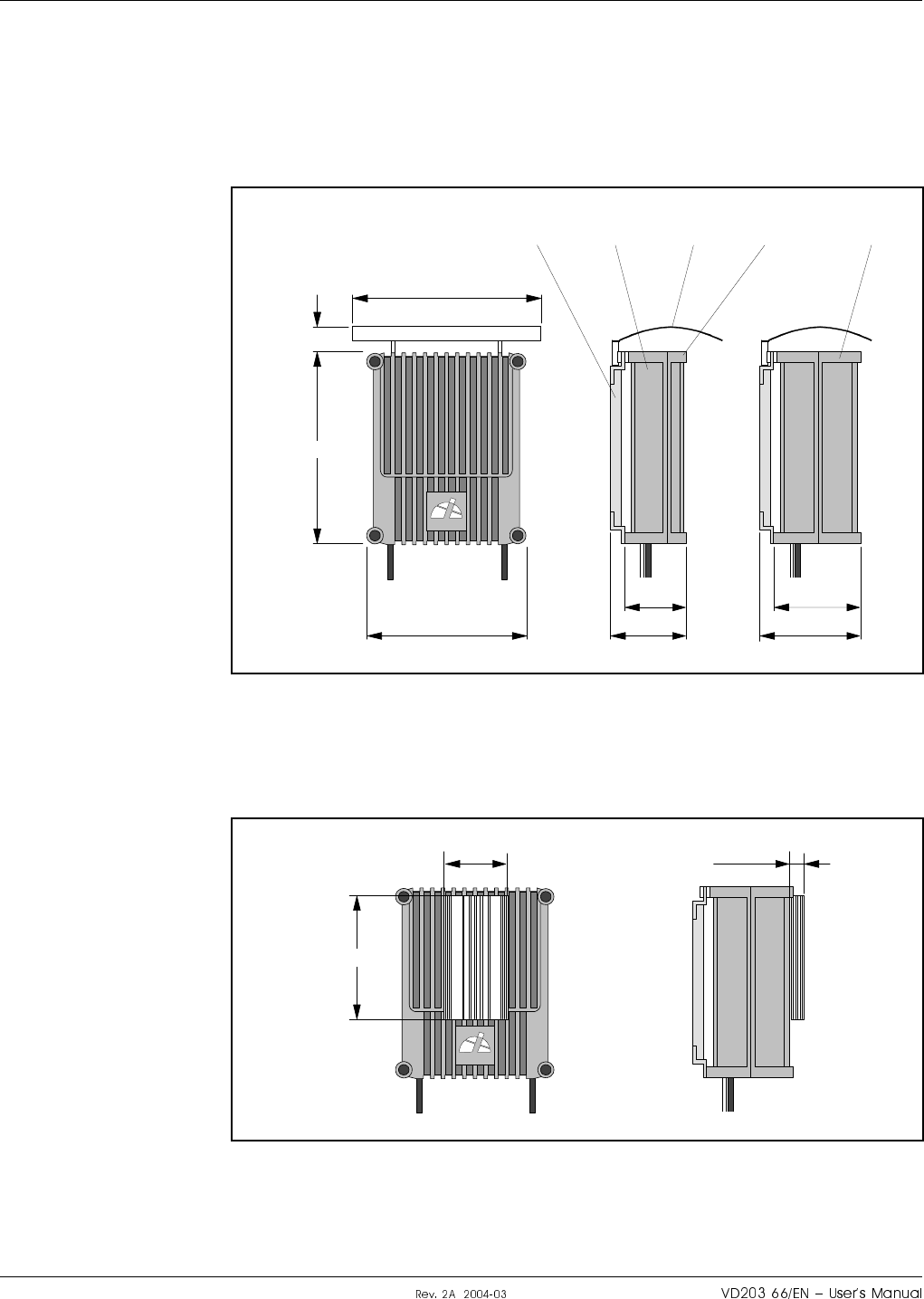
Dimensions and Weights
The dimensions of the repeater, including the mounting bracket, is shown
in Figure 3-1. The repeater chassis consists of two main parts, a cabinet in
which the circuitry is housed, and a cover, which can be either a low cover
or a high cover (see the figure) depending on the repeater type.
The high power CDMA and WCDMA repeaters have an external heat sink
on a high cover, see Figure 3-2.
440 (17.3")
530 (20.9")
520 (20.5"
)
110 (4.3")
ALLGON
174 (6.9")
224 (8.8")
240 (9.4")
290 (11.4")
Mounting bracket Cabinet Shelter Low cover High cover
Figure 3-1. Repeater dimensions
ALLGON
180 (7.1")
350 (13.8")
35 (1.4")
Figure 3-2. High power CDMA/WCDMA repeater
o#ff#cro H|H#H LGP Allgon AB
a¤

Approximately repeater weights
Repeater with a low cover ......................................................... 21 kg (46 lbs)
Repeater with an empty high cover .......................................... 25 kg (55 lbs)
Combined repeater with a high cover ...................................... 30 kg (66 lbs)
It is not recommended to remove the cover from the cabinet at the site.
However, if the cover, for some reason, has to be removed from the
cabinet, then disconnect the interconnection cables, close the cover,
remove the hinge shafts, and remove the cover.
The cabinet and cover weights are, approximately, as follows:
Empty low cover ........................................................................... 6 kg (13 lbs)
Empty high cover ....................................................................... 10 kg (22 lbs)
Equipped cabinet or high cover ................................................ 15 kg (33 lbs)
LGP Allgon AB H|H#H o#ff#cro
a
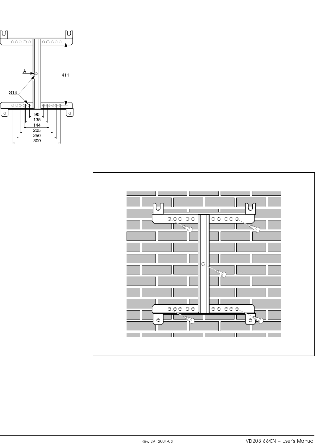
Mounting
The AR repeater is easy to mount using the provided mounting bracket,
which has Ø14mm (9/16") holes for 10mm (3/8") or 12mm (1/2") fixing
screws. Clamps with c-c measures of 90mm (3.5"), 135mm (5.3"), 144mm
(5.7"), 205mm (8.1"), 250mm (9.8"), and 300mm (11.8") can be used as
well. The vertical c-c measure for these are 411mm (16.2").
The mounting bracket is shown in the figure.
NOTE! There is a Ø14mm (9/16") single hole in the middle of the
mounting bracket, marked ’A’ in the figure, which is intended for a
locking screw, i.e. a screw which cannot be removed when the repeater is
put in the bracket.
Mount the repeater as follows:
1. Mount the provided bracket.
Normally, the repeater is mounted on a wall, pole, or mast. These
mounting cases are shown below.
Figure 3-3 shows a bracket attachment to a wall using four fixing
screws and a locking screw.
Figure 3-3. Attaching the bracket to a wall
o#ff#cro H|H#H LGP Allgon AB
aV
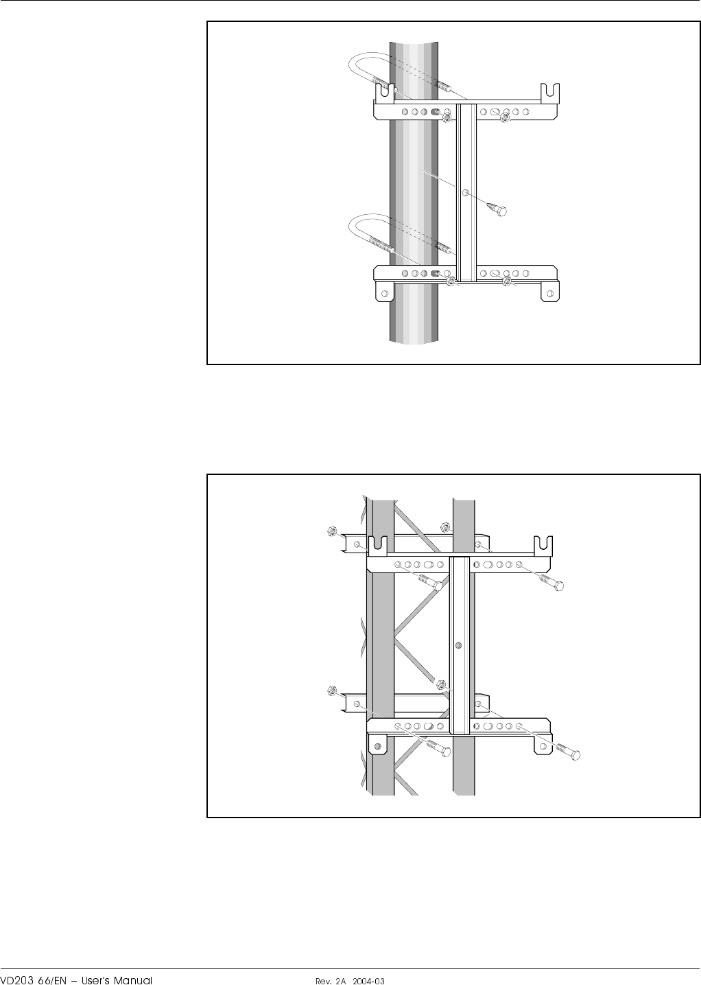
Figure 3-4 shows a bracket attachment to a pole using two 144mm
(5.7") U-shaped clamps and a locking screw.
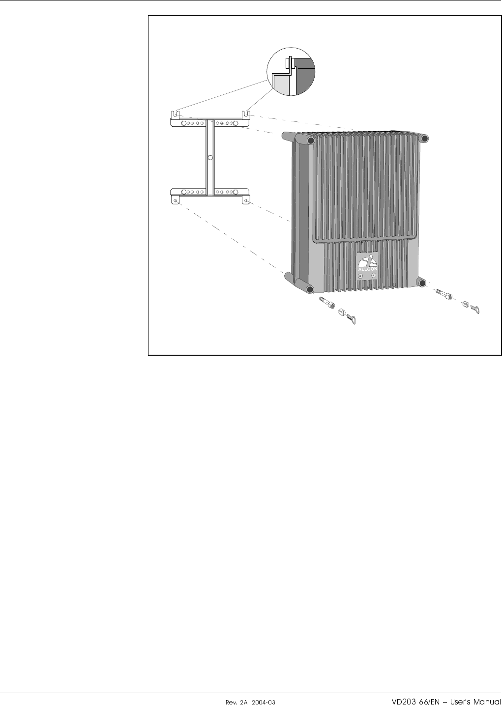
Figure 3-5 shows a bracket attachment to a mast using two 300mm
(11.8") bar-shaped clamps and no locking screw.
Figure 3-4. Attaching the bracket to a pole
Figure 3-5. Attaching the bracket to a mast
LGP Allgon AB H|H#H o#ff#cro
aS
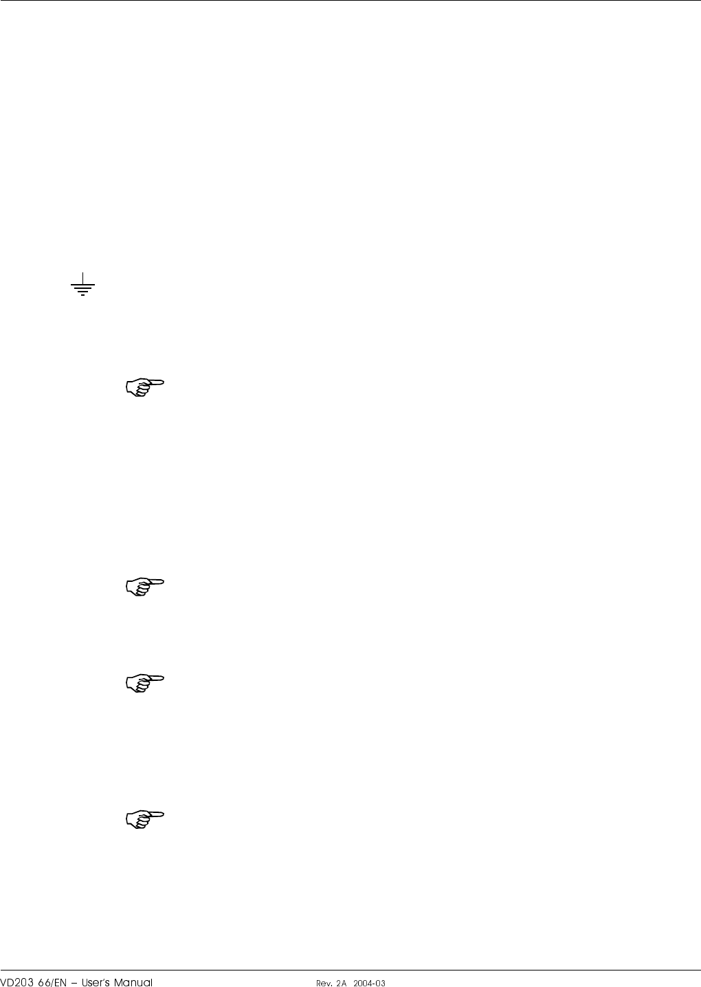
2. After attaching the bracket, hang the repeater on the upper supports
(see Figure 3-6) and use the screws for the lower ones. Tighten the
upper and lower screws.
There are locking cylinders that can be inserted and locked with a
key after the lower screws have been tightened (see Figure 3-6).
These prevents from unauthorized removal of the repeater.
3. Make sure the donor antenna, directed towards the base station
antenna, is mounted.
4. Make sure the service antenna, directed towards the area to be
covered by the repeater, is mounted.
Figure 3-6. Attaching the repeater to the bracket
o#ff#cro H|H#H LGP Allgon AB
a
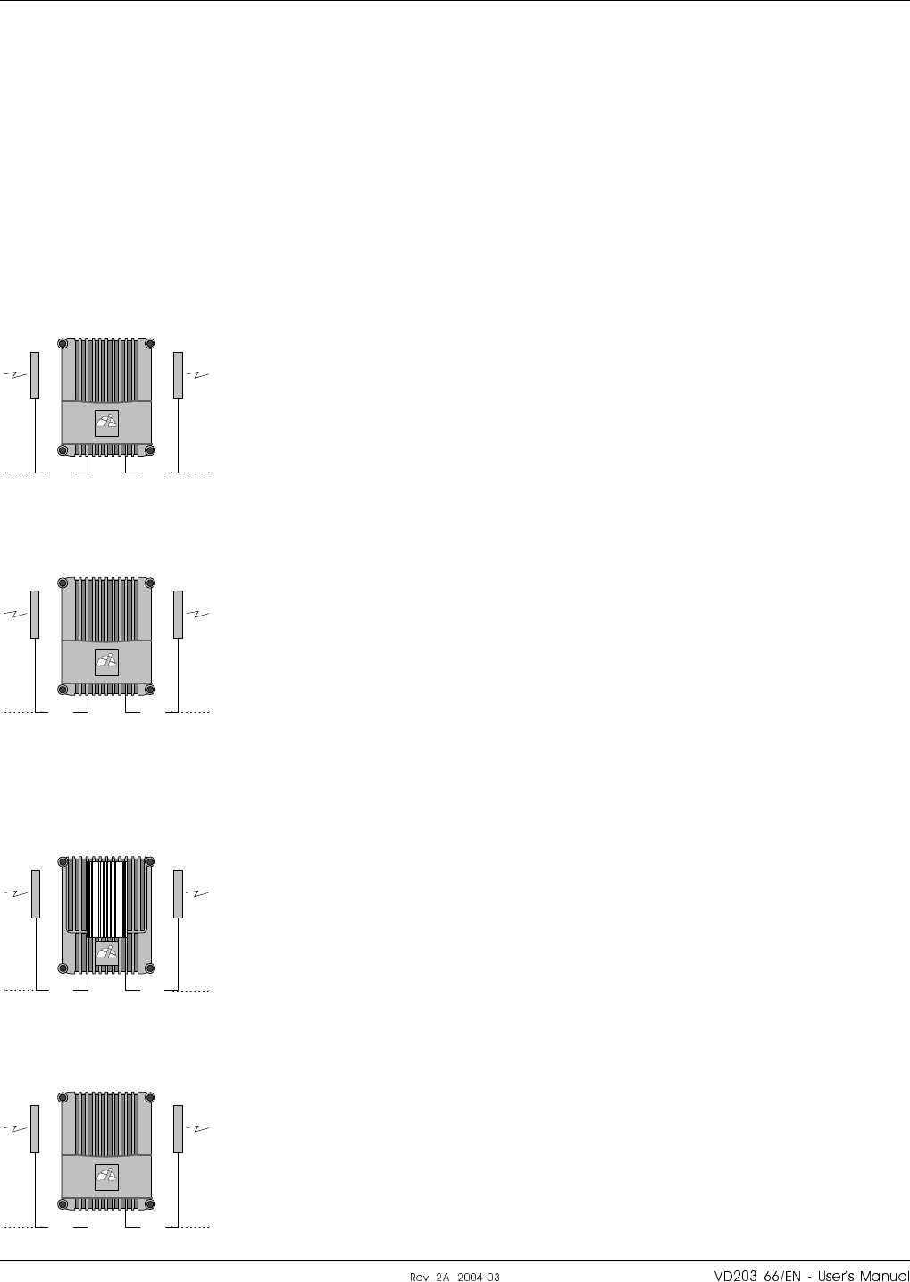
Connection
This section describes how to connect the input and output ports of the
repeater types:
AR repeaters (except for high power CDMA/WCDMA) ................ page 3-8
High power CDMA/WCDMA .................................................................... 3-9
BMU ............................................................................................................. 3-10
RMU ............................................................................................................. 3-11
FOR .............................................................................................................. 3-12
Common important instructions for the repeater types are found below.
Station ground
There is a screw to the left in the repeater that is intended for station
ground only. This screw is marked with the ground symbol.
Mains connection
Note that local regulations are to be followed for the mains connection.
The AR repeater is approved in accordance with EN and UL/cUL
regulations. This is, however, only valid if a classified power cord is used.
To get the repeater to meet these regulations, select one of the following
classified and approved cord types:
•EN – H 05 W5 - F HMR.
•UL – AWM Style 2587.
•CSA – AWM 1 A/B 11 A/B.
For outdoor use the power cord should meet at least IP65 encapsulation
requirements.
For repeaters supplied from the mains, the mains outlet must be grounded.
The mains connection described on the following pages means to mount
the mains plug to the mains cord (if to be used) but it does not mean to
connect the mains.
Do not turn the mains on until you are commissioning the repeater (see
Chapter 4, Commissioning).
RCU and RCC remote control units
All AR repeaters can be equipped with an RCU, Remote Control Unit.
The GSM antenna for this unit is internally connected in the repeater.
The RCU and its connection is described in Chapter 6, Optionals.
If the RCU is removed, then the jumper between pin 2 and 3 on the P27
port must be reconnected. Do not connect the jumper to another position
than between pin 2 and 3 on the P27 port.
An RCC, Remote Communication Control unit, is required if the unit is to
be connected to a FON board (the FON board does not support the RCU).
A description of the RCC and its connection is found in the VD203 67/EN,
ALR Compact Repeater, User’s Manual. See also Chapter 6, Optionals.
LGP Allgon AB H|H#H o#ff#cro
a
Connecting AR Repeater
This description is not applicable to a high power CDMA or WCDMA
repeater.
1. Connect the service and donor antenna coaxial cables (or RF cable
from the BTS if no donor antenna is used). Use N type male
connectors.
–The donor antenna or RF cable from the BTS is connected to the
right in the cabinet (’BS’ in Figure 3-7).
–The service antenna (MS) is connected to the left in the cabinet.
2. Connect station ground, if to be used (see page 3-7).
3. Mount the mains plug to the mains cord (if to be used) but do not
connect the mains (see page 3-7).
4. Connect external alarm and optional door open alarm, if this feature
is to be used. Descriptions are found on page 3-13.
5. Connect the R2R cables, if this feature is to be used (see page 3-14).
6. Connect a mains breakdown relay, if mains breakdown alarm is to be
used (see page 3-15).
MS
DPX
ANT
TEST
DC
-30 dB
-20 dB MS
DPX
ANT
TEST
DC
-30 dB
-20 dB
MS BS
OUT
LOW
IN+7V ATTOUT2 OUT1
LNA
DL
OUT
LOW IN ATT +7V OUT1 OUT2
LNA
UL
PSU
Mains
Figure 3-7. Connecting AR repeater
o#ff#cro H|H#H LGP Allgon AB
aI
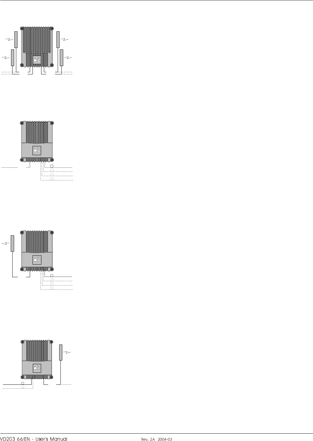
Connecting High Power CDMA or WCDMA Repeater
This description is applicable to a high power CDMA or WCDMA repeater.
1. Connect the service and donor antenna coaxial cables (or RF cable
from the BTS if no donor antenna is used). Use N type male
connectors.
–The donor antenna or RF cable from the BTS is connected to the left
in the cabinet (’BS’ in Figure 3-8).
–The service antenna (MS) is connected to the right in cabinet.
2. Connect station ground, if to be used (see page 3-7).
3. Mount the mains plug to the mains cord (if to be used) but do not
connect the mains (see page 3-7).
4. Connect external alarm and optional door open alarm, if this feature
is to be used. Descriptions are found on page 3-13.
5. Connect the R2R cables, if this feature is to be used (see page 3-14).
6. Connect a mains breakdown relay, if mains breakdown alarm is to be
used (see page 3-15).
MS
DPX
ANT
TEST
DC
-30 dB
-20 dB
MRX
MS
DPX
ANT
TEST
DC
-30 dB
-20 dB
BS MS
OUT
LOWIN+7V ATTOUT2 OUT1
LNA
DL
OUT
LOW IN ATT +7V OUT1 OUT2
LNA
UL
PSU
Mains
Figure 3-8. Connecting high power CDMA/WCDMA repeater
LGP Allgon AB H|H#H o#ff#cro
ap
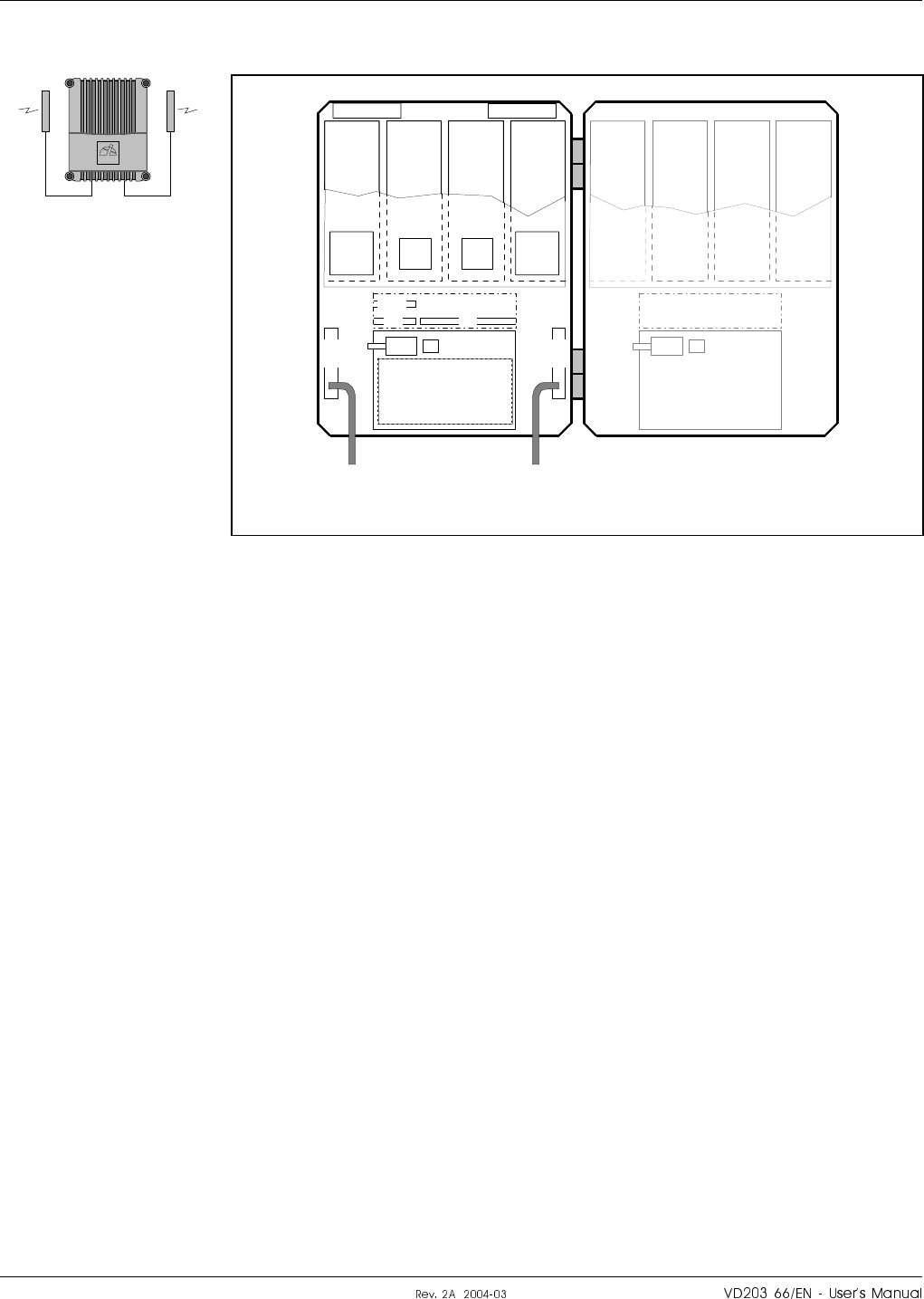
Connecting BMU
Figure 3-9 shows an BMU with separate RX/TX fiber optic cables to one
FOR. By using WDMs and OSPs, up to four FORs can be fed in parallel
by a BMU with double or single fiber communication. Up to eight FORs
can be fed with a high cover and two FOUs.
1. Connect the BTS antenna output RF cable to the ANT port of the
DC unit to the left in the cabinet. Use an N type male connector.
2. Connect an RF cable from the DPX port of the DC unit to the left in
the repeater to the BTS antenna. Use an N type male connector.
3. Connect the RX and TX fiber optic cables from the FON board
located in the upper part of the FOU to an FOR.
4. Connect station ground, if to be used (see page 3-7).
5. Mount the mains plug to the mains cord (if to be used) but do not
connect the mains (see page 3-7).
6. Connect external alarm, if this feature is to be used. Descriptions are
found on page 3-13.
7. Connect the R2R cables, if this feature is to be used (see page 3-14).
8. Connect a mains breakdown relay, if mains breakdown alarm is to be
used (see page 3-15).
P102
P130
Beryllium
oxide
hazard
P103
P101
P114
P108P112P111
P105
P110
P109P115
P106
P104
RX
TX
P113
FOU
FON
MS
DPX
ANT
TEST
DC
-30 dB
-20 dB
BTS TX RX
FOR
PSU
Mains
BTS antenna output
BTS antenna
Figure 3-9. Connecting BMU
o#ff#cro H|H#H LGP Allgon AB
au®
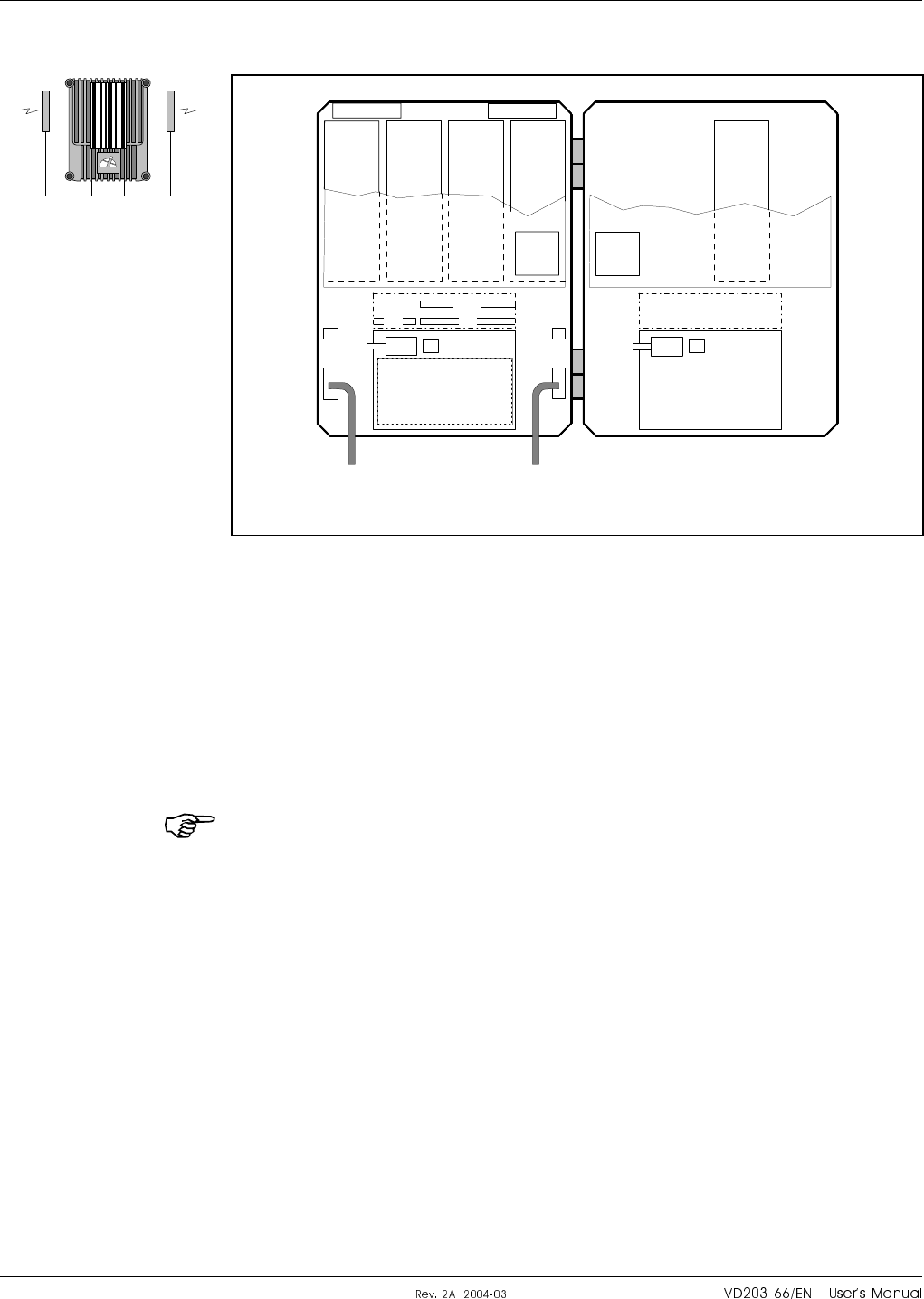
Connecting RMU
Figure 3-10 shows an RMU for donor antenna and separate RX/TX fiber
optic cables to one FOR. By using WDMs and OSPs, up to four FORs can
be fed in parallel by an RMU with double or single fiber communication.
Up to eight FORs can be fed with a high cover and two FOUs.
1. Connect the donor antenna coaxial cable to the right in the cabinet
(’BS’ in Figure 3-10). Use an N type male connector.
2. Connect the RX and TX fiber optic cables from the FON board
located in the upper part of the FOU to an FOR.
3. Connect station ground, if to be used (see page 3-7).
4. Mount the mains plug to the mains cord (if to be used) but do not
connect the mains (see page 3-7).
5. Connect external alarm and optional door open alarm, if this feature
is to be used. Descriptions are found on page 3-13.
6. Connect the R2R cables, if this feature is to be used (see page 3-14).
7. Connect a mains breakdown relay, if mains breakdown alarm is
available and is to be used (see page 3-15).
MS
DPX
ANT
TEST
DC
-30 dB
-20 dB
TX
BS
P102
P130
Beryllium
oxide
hazard
P103
P101
P114
P108P112P111
P105
P110
P109P115
P106
P104
RX
TX
P113
RX
OUT
LOW IN ATT +7V OUT1 OUT2
LNA
UL OUT
LOW
IN+7V ATTOUT2 OUT1
LNA
DL
FOU
FON
FOR
PSU
R2R
Mains
Figure 3-10. Connecting RMU
LGP Allgon AB H|H#H o#ff#cro
auu
Connecting FOR
Figure 3-11 shows a FOR for service antenna and separate RX/TX fiber
optic cables from a BMU. By adding WDMs and OSPs, a number of FORs
can be fed by one BMU with double or single fiber communication.
1. Connect the service antenna coaxial cable to the left in the cabinet
(’MS’ in Figure 3-11). Use an N type male connector.
2. Connect the RX and TX fiber optic cables from the BMU to the FON
board located in the upper part of the FOU.
3. Connect station ground, if to be used (see page 3-7).
4. Mount the mains plug to the mains cord (if to be used) but do not
connect the mains (see page 3-7).
5. Connect external alarm and optional door open alarm, if this feature
is to be used. Descriptions are found on page 3-13.
6. Connect the R2R cables, if this feature is to be used (see page 3-14).
7. Connect a mains breakdown relay, if mains breakdown alarm is to be
used (see page 3-15).
MS
DPX
ANT
TEST
DC
-30 dB
-20 dB
MS TX
P102
P130
Beryllium
oxide
hazard
P103
P101
P114
P108P112P111
P105
P110
P109P115
P106
P104
RX
TX
P113
OUT
LOW
IN+7V ATTOUT2 OUT1
LNA
DL
OUT
LOW IN ATT +7V OUT1 OUT2
LNA
UL
RX
FOU
FON
BMU
PSU
R2R
Mains
Figure 3-11. Connecting FOR
o#ff#cro H|H#H LGP Allgon AB
au¤
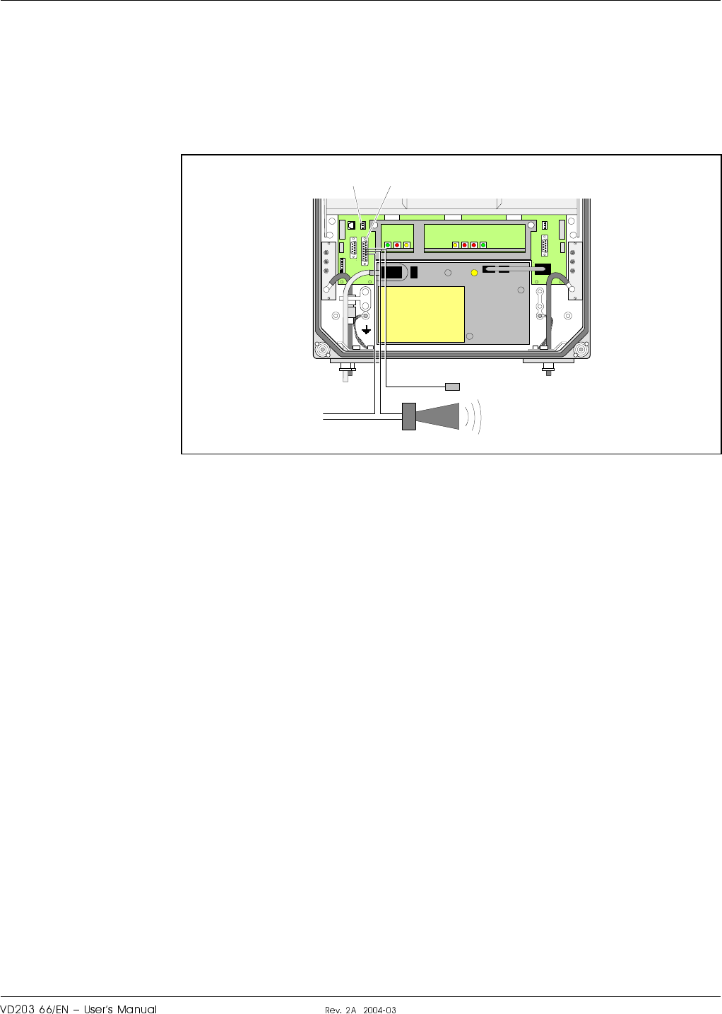
External Alarm
Burglary, fire or other external alarm can be used in the repeaters.
Optical or acoustic alarm can also be connected to the repeaters.
External alarm sensors and alarm signals are connected to the P33 alarm
port located to the left in the cabinet (see Figure 3-12).
The P33 alarm port is described in the Connection Ports section in
Chapter 5.
Use a 15 pole D-sub male connector for this connection.
The cable for this installation is taken through a strain relief bushing at
the bottom of the repeater.
For a repeater without a CU board, i.e. BMU, external alarm is connected
to the P109 port on the FON board. The P109 port is described in the
FON - Fiber Optic Node Board section in Chapter 5.
Door Open Alarm
A door open alarm can be used in all repeater types that have a CU
board, i.e. all types except for BMU. This is arranged with a door switch
connected to the P28 port (see Figure 3-12). The P28 port and the
connection is described in the Connection Ports section in Chapter 5.
MS
DPX
ANT
TEST
DC
-30 dB
-20 dB
P28 P33
MS
DPX
ANT
TEST
DC
-30 dB
-20 dB
External alarm sensors
External alarm
Figure 3-12. External alarm connection
LGP Allgon AB H|H#H o#ff#cro
au
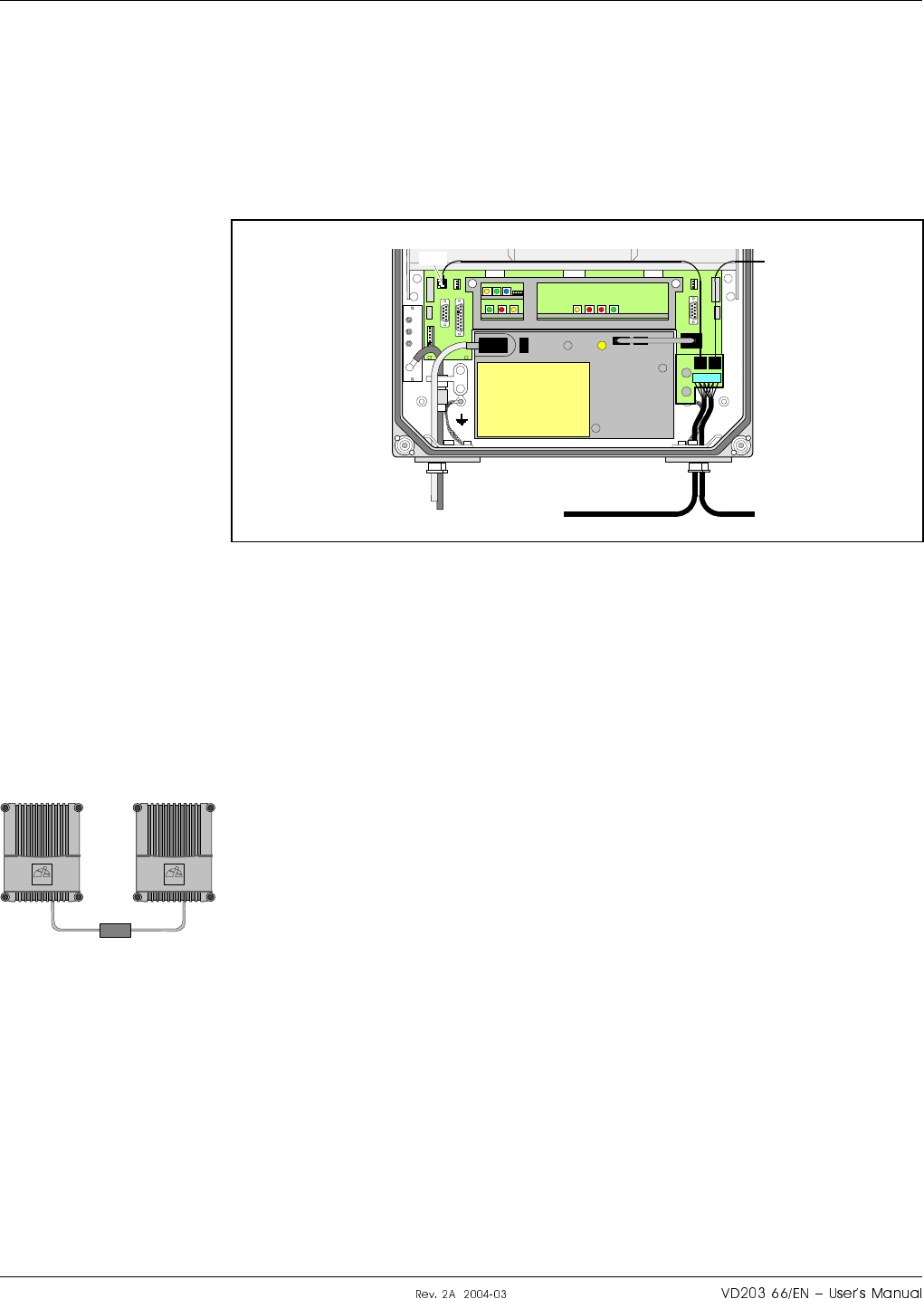
R2R, Repeater to Repeater Link
Connect the R2R cable, if this optional feature is to be used. See also the
F2F, Fiber to Fiber Link section below.
The R2R net cable is connected to the P34 Repeater to Repeater Link
port via the P1 terminal on the R2R connector board to the right in the
repeater (see Figure 3-13).
The P34, Repeater to Repeater Link port, is described in the Connection
Ports section in Chapter 5.
Any cable type can be used for indoor installation.
The following cable type is recommended for outdoor installation:
Li 2YC11Y, 2x2xAWG24/222, non-halogen, Metrofunkkabel-Union.
Use a strain relief bushing or a connector at the bottom of the repeater
for the external net cable.
If the link cable between two repeaters in an R2R net is longer than
25 meters, then an RS-485 repeater is required, see the figure.
Further information about the Repeater to Repeater Link is found in the
VD202 91/EN, R2R, Repeater to Repeater Link Kit, Installation Guide.
F2F, Fiber to Fiber Link
F2F is a feature that makes it possible to communicate with all repeaters
that have a FON board (i.e. BMU, RMU and FOR) and are included in
the same fiber optic net. By using the existing fiber optic distribution net,
no wire or other communication device is required.
Communication with repeaters works also in mixed F2F and R2R net.
MS
DPX
ANT
TEST
DC
-30 dB
-20 dB
P31
P3 P2
P1
Figure 3-13. R2R connection
>25m
ALLGONALLGON
o#ff#cro H|H#H LGP Allgon AB
auV
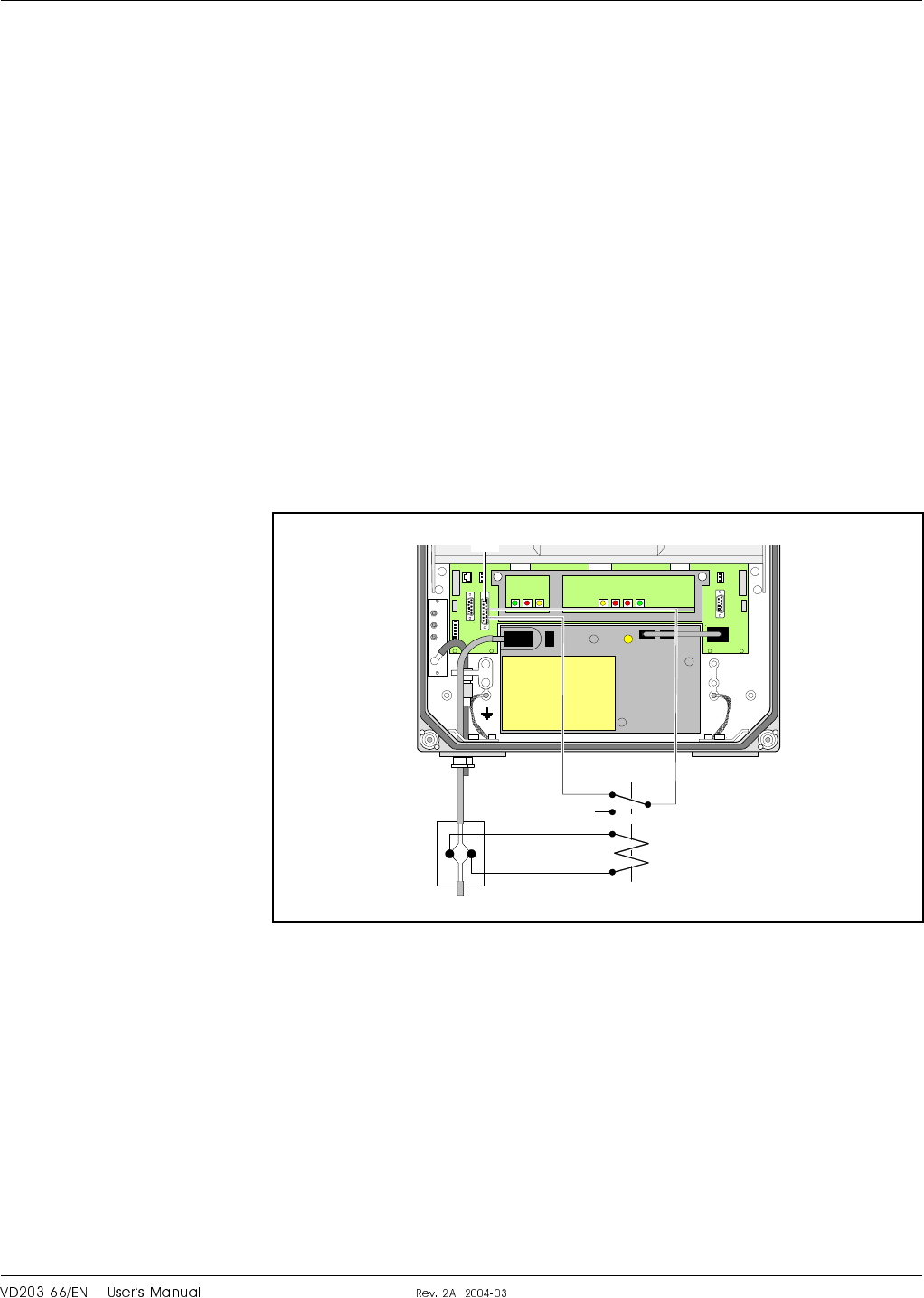
Mains Breakdown Relay
To be able to distinguish PSU faults from power failure, a mains
breakdown relay can be used.
The mains breakdown relay is not included in the repeater. So, it has to
be mounted outside the repeater chassis. The relay intended for this
purpose must fulfil the following specifications:
Relay specification
Closing time: Max. 30 milliseconds.
Insulation coil/contact: Min. 4KV.
Mains connected relay must be in compliance with valid local regulations.
Connection
1. Connect a currentless closed relay contact to pin AI1 and AIC on the
P33 alarm connector see Figure 3-14. Alarm is initiated by short
circuiting pin AI1 and AIC in the P33 connector.
The P33 alarm port is described in the Connection Ports section in
Chapter 5.
2. Connect the relay coil. It must be supplied from the same fuse as the
repeater.
3. After commissioning, select the Mains Breakdown option in the alarm
configuration dialog box in the OMT32 or OMS program. Refer to the
OMT32, User’s Manual or the Advanced Repeater OMS, User’s
Manual.
MS
DPX
ANT
TEST
DC
-30 dB
-20 dB
P33:AICP33:AI1
P33
Figure 3-14. Mains breakdown relay connection
LGP Allgon AB H|H#H o#ff#cro
auS

Finishing the Installation
Check all connections made.
If a 24 Volt or 48 Volt power supply unit is to be used, then replace the
PSU as described in the next section.
When ready with the installation, commission the repeater as described in
Chapter 4, Commissioning.
o#ff#cro H|H#H LGP Allgon AB
au
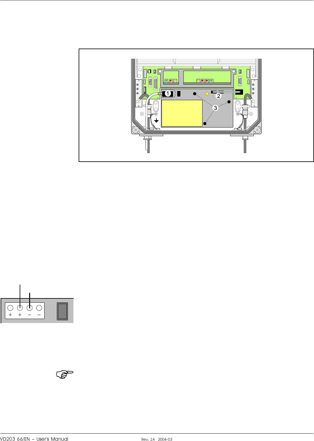
Installing 24V or 48V DC Power Supply Unit
The 220V AC PSU can be replaced with a 24 Volt or 48 Volt DC PSU as
described below.
1. Switch the repeater off and remove the mains plug from the PSU
(’1’ in Figure 3-15).
2. Disconnect the two connectors (2) on the PSU.
3. Loosen the three fixing screws (3) using a 5mm Allen key.
4. Remove the PSU from the repeater.
5. Mount the 24/48 Volt DC PSU with the three fixing screws (3).
6. Connect the PSU to the DIA board (2).
7. Connect the DC power cable. The supplied cable should have a
radiation limiter. The cable shall be connected as follows:
The + pole shall be connected to one of the left terminals in the PSU
connector with the brown part of the DC cable.
The – pole shall be connected to one of the right terminals in the
PSU connector with the blue part of the DC cable.
8. Switch the repeater on.
9. The yellow LED on the PSU shall now be lit.
The DC Power Supply Unit must be galvanically separated from the mains
supply with an equipment fulfilling the IEC65 safety requirements.
MS
DPX
ANT
TEST
DC
-30 dB
-20 dB
MS
DPX
ANT
TEST
DC
-30 dB
-20 dB
PSU
Figure 3-15. Replacing mains PSU with 24V or 48V
Blue
Brown
LGP Allgon AB H|H#H o#ff#cro
au

o#ff#cro H|H#H LGP Allgon AB
auI
4. Commissioning
Read carefully Chapter 1 Safety before commissioning the repeater.
Check all connections made during the installation.
To fulfill the IP65 weather protective requirements, ensure that the cable
strain relief bushings are properly tightened. Also, ensure that the gaskets
at the cable inlets and on the cabinet are properly fitted and not damaged.
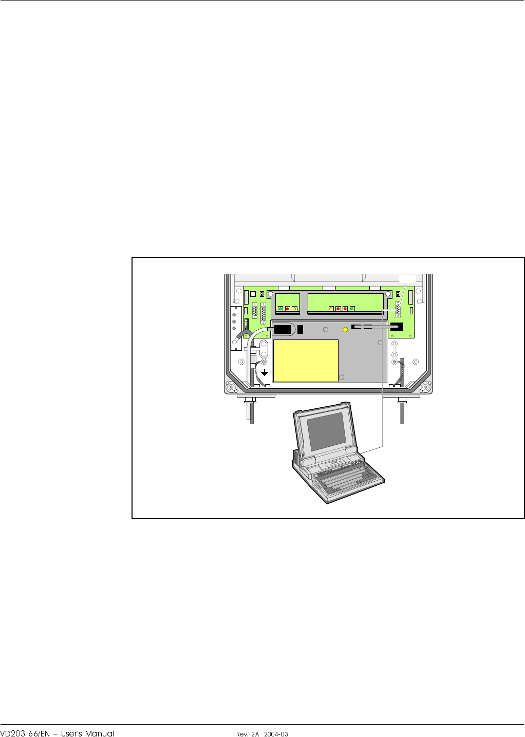
Preparing for setup
You can set up a repeater locally by connecting a PC loaded with the
OMT32 software.
A COM port on the PC is connected to the P31 PC port (RS-232) located
to the right in the cabinet (see Figure 4-1). Use the provided serial cable.
The P31 PC port is described in the Connection Ports section in Chapter 5.
Finally, make sure the repeater is connected to the mains.
Now, you can use OMT32 to set up and control the repeater. The OMT32
program is described in the OMT32, User’s Manual.
For repeaters without DIA board (e.g. BMU without donor antenna) the
PC is connected to the P106 port on the FON board. The P106 port is
described in the FON - Fiber Optic Node Board section in Chapter 5.
MS
DPX
ANT
TEST
DC
-30 dB
-20 dB
P31
Figure 4-1. Connecting a PC for local setup
LGP Allgon AB H|H#H rjjccrocoX
Vau

Starting the Repeater
1. Turn the mains switch on (marked ’S’ in Figure 4-2).
2. Check the LED on the power supply unit (V). It must be lit with a
steady yellow light.
3. Check the four CU board LEDs (see Figure 4-2). A correct power up
is indicated as follows:
POWER
Yellow LED that is lit with a steady light after the mains is switched
on. Indicates present power.
BOOT
Red LED that is lit with a steady light when the system boots, i.e. for
10 – 15 seconds after the mains is switched on. Then, it flashes for
the next 5 – 10 seconds. After that, if no error is detected, the LED is
off.
FAULT
Red LED that flashes 15 – 20 seconds after the mains is switched on.
Then, it flashes for less serious alarms (ERROR) and is lit with a
steady light for fatal alarms (CRITICAL).
OPER
Green LED that lights up approx. 15 seconds after the mains is
switched on. It shows, with a steady light, that the unit is ready for
operation.
4. Check the three ALI board LEDs (see Figure 4-2). The LEDs follow
the alarm relays. A correct power up is indicated as follows:
OPER
Green LED that has the same indication as the green LED on the CU
board (see above).
FAULT
Red LED that is lit with a steady light for ERROR and CRITICAL
alarms.
POWER
Yellow LED that has the same indication as the yellow LED on the
CU board (see above).
When the indicators show operational mode, the repeater can be
configured for operation by using a computer running OMT32. This is
further detailed in the OMT32, User’s Manual.
rjjccrocoX H|H#H LGP Allgon AB
Va¤
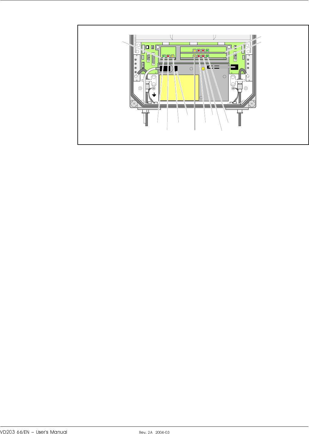
Indicators in the Cabinet
Figure 4-2 shows the repeater indicators and the mains switch in the
cabinet.
Figure 4-2 is, however, not applicable to the BMU type that uses the
indicators on the FON board. The FON board indicators are described in
the FON - Fiber Optic Node Board section in Chapter 5.
MRX indicators
An optional MRX board for CDMA repeaters has the same set of
indicators as the CU board (POWER, BOOT, FAULT and OPER). The
function of these MRX indicators are also the same as for the CU board
(described in the previous section).
R2R, Repeater to Repeater Link indicators
Additional indicators are found in the repeater, if equipped with the
Repeater to Repeater Link feature. For information about these indicators,
refer to the VD202 91/EN R2R, Repeater to Repeater Link Kit, Installation
Guide.
F2F, Fiber to Fiber Link indicator
An additional green F2F indicator is found on the FON board in the
BMU, RMU and FOR types. This indicator is further described in the
FON - Fiber Optic Node Board section in Chapter 5.
MRX
DPX
ANT
TEST
DC
-30 dB
BS
-20 dB
MRX
DPX
ANT
TEST
DC
-30 dB
OPER
FAULT
POWER
POWER
BOOT
FAULT
OPER
CU
ALI
SV
MR
X
Figure 4-2. Internal indicators and mains switch
LGP Allgon AB H|H#H rjjccrocoX
Va
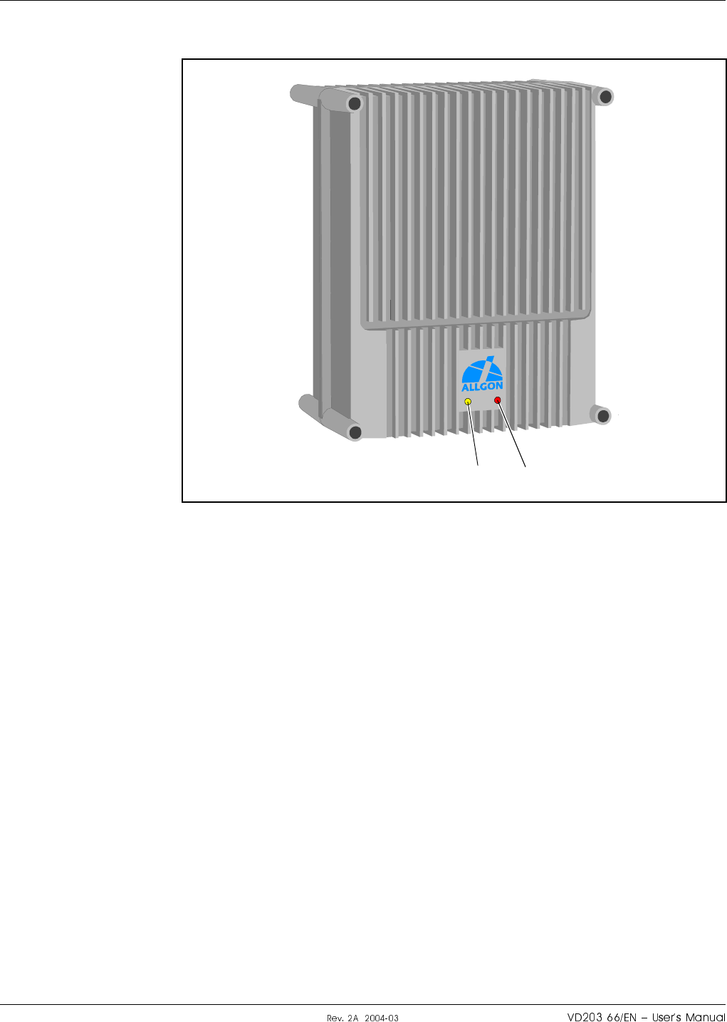
Indicators on the Repeater Front
After commissioning the repeater, the cover is closed and the following
indicators on the repeater front are visible:
Yellow
Operation LED that lights up approx. 15 seconds after the mains is
switched on. At steady light the repeater is ready for operation.
Red
Alarm LED that indicates ERROR alarms with flashing light and
CRITICAL alarms with steady light.
Yellow Red
Figure 4-3. External indicators
rjjccrocoX H|H#H LGP Allgon AB
VaV
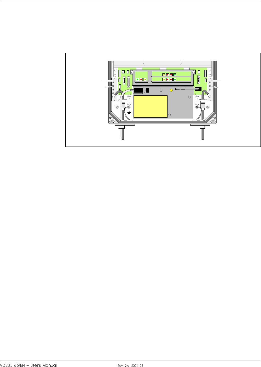
Measuring the Output Signal Level
Uplink and downlink output signal test ports are found on the directional
couplers (DC) at the MS and BS antenna connectors. These test ports are
marked TEST –30dB (see Figure 4-4) and are intended for signal
measuring using e.g. a spectrum analyzer.
The coupling is –30dB approximately. There is no directivity in these test
ports, i.e. both uplink and downlink signal can be measured.
MRX
DPX
ANT
TEST
DC
-30 dB
BS
-20 dB
MRX
DPX
ANT
TEST
DC
-30 dB
DC
TEST
–30 dB
DC
TEST
–30 dB
Figure 4-4. Measuring ports for output signal level
LGP Allgon AB H|H#H rjjccrocoX
VaS

Voltage Supply Testpoints
A number of voltage supply testpoints are available in the repeater. These
testpoints are named U7A – U7F for the 7V supply voltages and U26 for
the 26V or 13V supply voltage (26V or 13V depending on the repeater
type).
A standard multi-meter can be used on these testpoints.
The testpoints are found on the DIA board in the repeater cabinet. The
testpoint positions on the DIA board is detailed in the Board and Unit
Descriptions section in Chapter 5.
If the repeater is equipped with a second PSU, e.g. for combined
channel/band selective operation, the same set of testpoints are also found
on the cover DIA board.
Repeater Configuration
The repeater is now ready to be configured in accordance with the site
conditions and system performance requirements. Pay especial attention
to the antenna isolation described in the OMT32, User’s Manual.
rjjccrocoX H|H#H LGP Allgon AB
Va

5. Functional Description
This chapter contains a short general description. After that you will find
descriptions of the various repeater types on a unit level, including
repeater types, design, block diagrams, board and sub unit descriptions,
connection ports, and cabling.
General Description
LGP Allgon AR repeaters work as bi-directional on-frequency amplifiers.
A repeater receives, amplifies, and retransmits signals downlink and
uplink simultaneously, i.e. from the base station via the repeater to the
mobile stations and from the mobile stations via the repeater to the base
station.
The repeater can be connected to a BS donor antenna, directed towards
the base station, and to an MS service antenna directed towards the area
to be covered. These antennas are connected to the repeater with N type
male connectors.
The repeaters can also be connected via RF cables or fiber optic cables
instead of donor or service antennas.
To prevent instability due to poor antenna isolation, a built-in antenna
isolation supervision feature reduces the gain level automatically when
poor antenna isolation is detected. For channel selective CDMA repeaters,
poor antenna isolation is detected and managed by means of an MRX unit
(Measurement Receiver).
The LGP Allgon repeaters are controlled by powerful microprocessors.
Alarm and operational status LEDs are visible on the repeater front.
The repeater works with convection cooling without fan.
Operational parameters, such as gain, channel number, power levels, etc.
are set using a desktop or notebook and LGP Allgon OMT32, which
communicate, locally or remotely via modem, with the repeater. Remote
operation is performed via PSTN or a GSM net.
LGP Allgon AB H|H#H ¦o6cro#fH6c|cro
Sau
Repeater Types
The main repeater types are listed in Chapter 2, Introduction, where you
also will find some examples on how to use the various repeater types to
build up a fiber optic network and antennas for covering a desired area.
The main repeater types are further described in this and the following
sections. As all the described repeater types can be configured differently,
this description is applicable only to standard configured repeaters.
Channel Selective GSM Repeater
A channel selective GSM repeater can be equipped with two, four, six or
eight channels. This repeater type is used for channel selective systems
such as GSM, DCS, PCN and PCS.
The channel selective GSM repeater has an RF port for a donor antenna
(or RF cable) and an RF port for a service antenna (or RF cable).
Channel Selective CDMA/WCDMA Repeaters
A channel selective CDMA or WCDMA repeater can be equipped with one
or two channels. These repeater types are used for digital code division
systems in accordance with IS-95 or J-std-008 standard, and wideband
digital code division systems.
The channel selective CDMA/WCDMA repeaters have an RF port for a
donor antenna (or RF cable) and an RF port for a service antenna (or RF
cable).
Channel Selective High Power CDMA/WCDMA Repeaters
These are CDMA/WCDMA repeaters equipped with a 6dB (typically) BA
(Booster Amplifier) in the downlink transmitting signal path.
The channel selective high power CDMA/WCDMA repeaters have an RF
port for a donor antenna (or RF cable) and an high power RF port for a
service antenna (or RF cable).
Band Selective Repeater
The band selective repeater has an adjustable bandwidth. This repeater
type is used for analog or digital systems such as NMT, GSM, TACS,
ETACS, AMPS, DAMPS, CDMA and WCDMA.
The band selective repeater has an RF port for a donor antenna (or RF
cable) and an RF port for a service antenna (or RF cable).
RF RF
ALLGON
RF RF
ALLGON
RF RF
ALLGON
RF RF
ALLGON
¦o6cro#fH6c|cro H|H#H LGP Allgon AB
Sa¤
Combined Repeater
Some of the repeater types can be combined in the same repeater chassis
and be in operation in parallel.
One repeater part is located in the chassis cabinet and the second
repeater part is located in a high cover.
The combined repeater has normally two RF ports for donor antennas (or
RF cables) and two RF ports for service antennas (or RF cables).
BMU, Base Station Master Unit
A BMU is one of the RF repeater types equipped with a FOU (Fiber Optic
Unit) that makes the repeater receive and transmit optic signals on the
service side.
The BMU has an RF port for BTS connection and up to four fiber optic
ports that can be connected to FORs.
By using WDMs and OSPs, up to four FORs can be fed in parallel by a
BMU with double or single fiber communication. Up to eight FORs can be
fed with a high cover and two FOUs.
RMU, Repeater Master Unit
An RMU is one of the RF repeater types equipped with a FOU (Fiber
Optic Unit) that makes the repeater receive and transmit optic signals on
the service side.
The RMU has an RF port for a donor antenna and up to four fiber optic
ports that can be connected to FORs.
By using WDMs and OSPs, up to four FORs can be fed in parallel by an
RMU with double or single fiber communication. Up to eight FORs can be
fed with a high cover and two FOUs.
FOR, Fiber Optic Repeater
A FOR is one of the RF repeater types equipped with a FOU that makes
the repeater receive and transmit optic signals on the donor side.
The FOR has a fiber optic donor port and an RF port for a service
antenna (or RF cable).
By using a splitter, another FOR can be connected in serial.
This unit can be connected to a BMU, RMU or FOR (with splitter).
RF RF
ALLGON
ALLGON
RF
ALLGON
RF
RF
ALLGON
LGP Allgon AB H|H#H ¦o6cro#fH6c|cro
Sa

Repeater Design
The repeater is housed in a cast aluminium chassis that is waterproof,
class NEMA4/IP65, for outdoor use. The chassis has a design suited for
outdoor use as well as indoor use.
The chassis consists of a cabinet and a cover joined with hinges. The
cabinet contains the repeater circuitry. The cover can be either a low
cover or a high cover. The latter consists of another cabinet which can be
used as an empty cover or be equipped as a part of the repeater or as an
independent repeater unit.
Inside the repeater, a number of amplifier boards are individually shielded
and located under a metal cover that can be folded out. These amplifier
boards are of different types depending on the supported system.
A repeater with a high cover that is equipped as two independent repeater
units (Combi) can, for example, be equipped for channel selective
operation in the cabinet and band selective operation in the cover.
Functionally, all the repeater types are built up with a number of sub
units. These are listed below and pointed out in the following sections.
Sub Unit Overview
The main repeater sub units are:
CHA, Channel Amplifier board
Channel selective GSM repeaters can handle up to eight repeater channels
(four if the CU part number is K103/1). For every even number of
repeater channels, two CHA amplifier boards are required in the repeater,
one CHA board for uplink signaling and one board for downlink signaling.
Each repeater channel is allocated to a radio channel or switched off. In a
GSM type TDMA system (GSM, EGSM, DCS1800 or PCS1900), one
repeater channel can handle eight calls (sixteen if half-rate encoding is
used).
CSA, CDMA/WCDMA Segment Amplifier board
Channel selective CDMA/WCDMA repeaters can handle two CDMA or
WCDMA repeater channels. For every even number of repeater channels,
two CSA amplifier boards and two PA amplifier boards are required in
the repeater, one pair of CSA/PA boards for uplink signaling and one pair
for downlink signaling. Each repeater channel is allocated to a radio
channel or switched off.
BSA, Band selective amplifier board
Band selective repeaters can handle multi-carriers over a wide band. The
bandwidth is adjustable. A band selective repeater channel requires two
BSA boards and two PA amplifier boards in the repeater. One pair of
BSA/PA boards for uplink signaling and one pair for downlink signaling.
¦o6cro#fH6c|cro H|H#H LGP Allgon AB
SaV

PA, Power Amplifier board
This is a power amplifier board that can handle two repeater channels.
For every even number of repeater channels, two PA amplifier boards are
required in the repeater, one pair for uplink signaling and one pair for
downlink signaling.
The PA board is used with CSA boards in CDMA and WCDMA repeaters,
and with BSA boards in band selective repeaters.
BA, Booster Amplifier
CDMA and WCDMA repeaters can be equipped with a high power booster
amplifier that boosts the output gain with typically 6dB. A high power
CDMA or WCDMA repeater can operate with maximum two channels.
DIA, Distribution board
The DIA board is a distribution board on which all other boards and units
are connected to.
A DIA board is found in the cabinet. Another DIA board is found in the
cover, if equipped as an independent repeater.
On the DIA board, there is a shielded metal frame in which the CU, ALI
and MRX boards are located.
CU, Control Unit board
The CU board is the control unit of the repeater.
The CU board is found in the right part of the shielded DIA board frame.
ALI, Alarm Interface board
The ALI board handles alarm and alarm communication.
The ALI board is found in the left part of the shielded DIA board frame.
DC, Directional Coupler
DC units are used as antenna signal directional couplers.
DC units are found in shielded boxes to the left and right in the cabinet
(at the antenna flanges) and in some repeater types also in the cover.
LNA, Low Noise Amplifier
LNA amplifiers are used as uplink and downlink low noise branch
amplifiers.
LNA units are found in shielded boxes in the upper part of the cabinet. In
some types, they can also be found in the upper part of the cover.
LGP Allgon AB H|H#H ¦o6cro#fH6c|cro
SaS

DPX, Duplex filter
Duplex filters are found on the cover plate over the amplifier boards.
CMB, Combiner unit
CMB units are found on the cover plate over the amplifier boards in
channel selective repeaters with more than two channels, and in combined
repeaters.
MRX, Measurement Receiver board
Channel selective CDMA repeaters can be equipped with an MRX unit.
For such a repeater, an MRX board is found in the right part of the
shielded DIA board frame.
FOU, Fiber Optic Unit
The FOU is, in the simplest configuration, a metal plate on which a FON
board (or the earlier FOT board), a duplex filter and fiber optic
connectors are assembled. The FOU can, however, be configured with
combiners, OSPs and WDMs to obtain a desired combination of several
branches with double or single fiber communication.
The FOU is used in BMUs, RMUs and FORs.
FON, Fiber Optic Node board
The FON board is a unit that converts RF signals to optic signals and the
other way round. Also, it supervises the RF and optical signals and
generates alarm if an error occurs. Actually, it has most of the repeater
functions except for channel boards.
The FON board is built up on a printed circuit board that also contains
battery backup.
The FON is the main part of the FOU.
FOT, Fiber Optic Transceiver
The FOT unit is an earlier version of the FON board. It converts RF
signals to optic signals in the same way as the FON board, but it has not
as many functions as the FON board.
The FOT is the main part of the FOU.
PSU, Power Supply Unit
In all the repeater types, a PSU is found downmost in the cabinet. In
some types, it can also be found in the cover.
¦o6cro#fH6c|cro H|H#H LGP Allgon AB
Sa

RCU, Remote Control Unit (optional)
The RCU is an optional communication unit for remote control of the
repeaters via PSTN or GSM modems.
The RCU unit is further described in Chapter 6, Optionals.
RCC, Remote Communication Control unit (optional)
The RCC is an optional communication unit for remote control of the
repeaters via PSTN or RF modems.
An RCC, Remote Communication Control unit, is required if the unit is to
be connected to a FON board (the FON board does not support the RCU).
A description of the RCC and its connection is found in the VD203 67/EN,
ALR Compact Repeater, User’s Manual. See also Chapter 6, Optionals.
The RCC unit is the latest version of remote control units, also used in
the Compact repeaters.
RIA, Repeater to Repeater Interface Adapter (optional)
If the repeater is equipped with an optional R2R feature, then a RIA
board is found in the left part of the shielded DIA board frame.
For further information about the Repeater to Repeater Link feature, refer
to the VD202 91/EN R2R, Repeater to Repeater Link Kit, Installation
Guide.
LGP Allgon AB H|H#H ¦o6cro#fH6c|cro
Sa
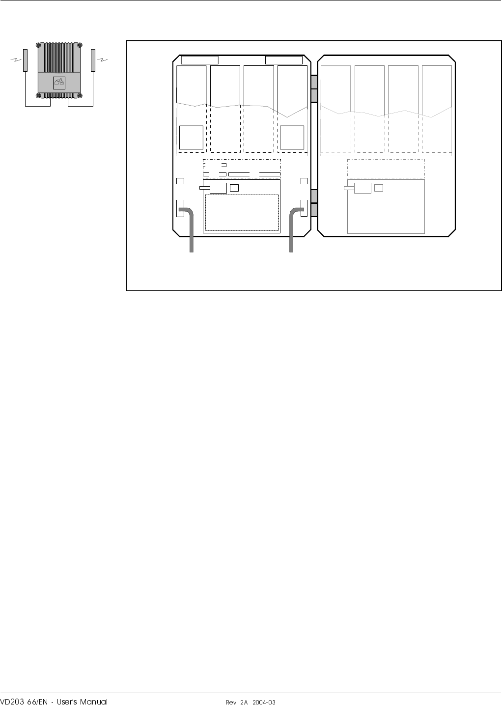
Sub Units in a Channel Selective GSM Repeater
A cabinet (the left part in Figure 5-1) for a channel selective GSM
repeater can be equipped with four CHA channel boards, two downlink
boards (DL) with two internal channels each and two uplink boards (UL)
with two internal channels each. The described cabinet has a capacity of
four bi-directional GSM channels.
The cover (the right part in Figure 5-1) can be equipped as well, which
gives up to eight GSM channels. The cover board positions are shown in
the figure.
Channel selective GSM repeaters are used for GSM, DCS and PCS types
of TDMA systems.
Sub units:
ALI Alarm Interface board.
CHA Channel Amplifier board.
CMB Combiner unit.
CU Control Unit board.
DC Directional Coupler.
DPX Duplex filter.
LNA Low Noise Amplifier.
PSU Power Supply Unit.
RIA Repeater to Repeater Interface Adapter board (optional).
RCU Remote Control Unit (optional).
ALLGON
LNA - DL
1234
LNA - UL
PSU
(RCU)
DPX
MS
(RIA)
CUALI
DC
MS DC
BS
DPX
BS
CHA1
DL
2
CHA2
DL
2
CHA3
UL
2
CHA4
UL
2
MS BS
CMB
DL CMB
UL
1234
CHA1
DL
2
CHA2
DL
2
CHA3
UL
2
CHA4
UL
2
5678
CHA5
DL
2
CHA6
DL
2
CHA7
UL
2
CHA8
UL
2
PSU
MS = To mobile station antenna BS = To base station antenna
Figure 5-1. Sub units in a GSM repeater
¦o6cro#fH6c|cro H|H#H LGP Allgon AB
SaI

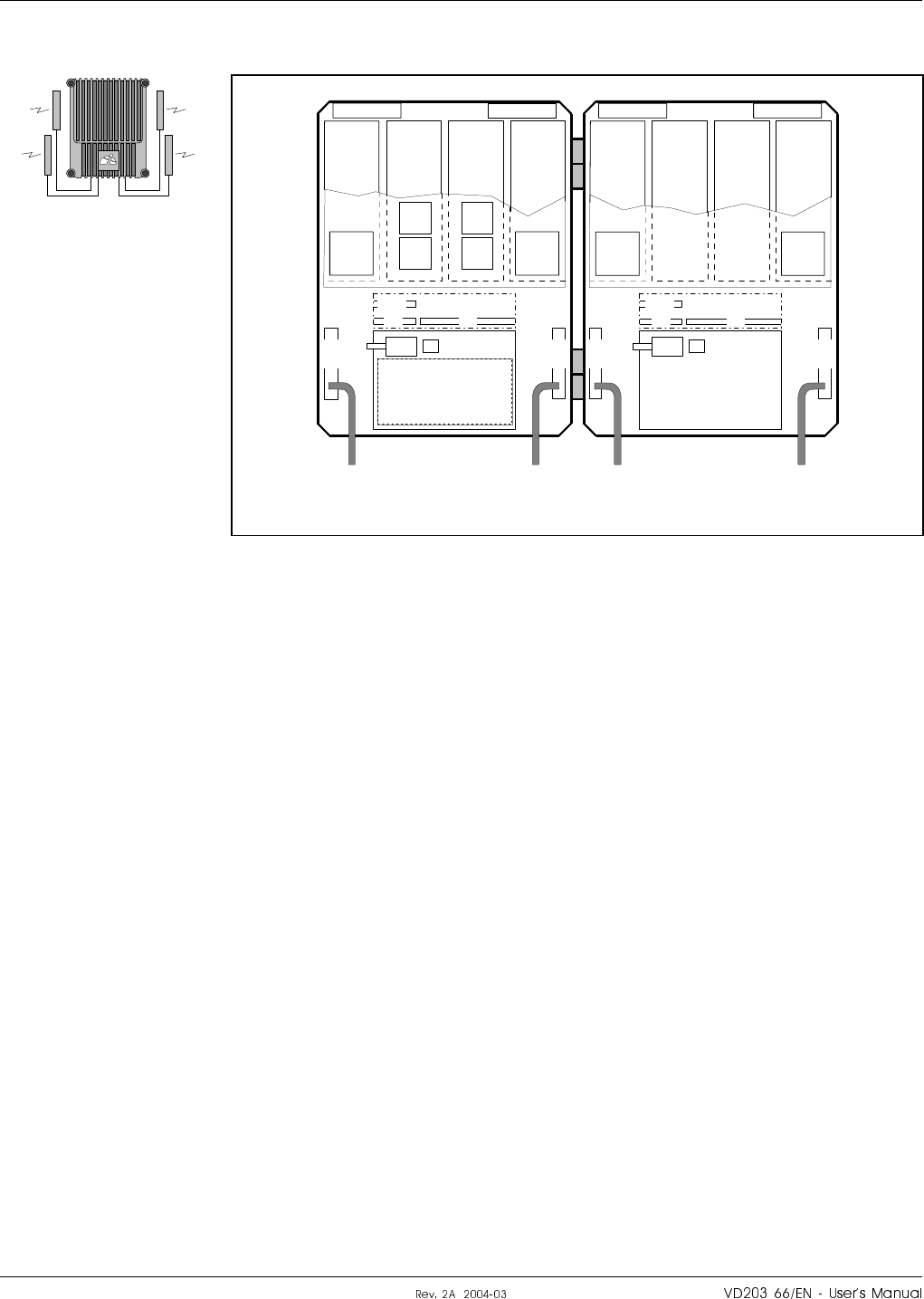
Sub Units in a Channel Selective CDMA/WCDMA Repeater
A cabinet (the left part in Figure 5-2) for a channel selective CDMA or
WCDMA repeater can be equipped with two pair of CSA and PA boards,
one pair for downlink (DL) and one pair for uplink (UL). The described
cabinet has a capacity of two bi-directional CDMA or WCDMA carriers.
The cover (the right part in Figure 5-2) can be equipped as well, which
gives up to four CDMA or WCDMA channels. The cover board positions
are shown in the figure.
CSA boards are used for IS-95 or J-STD-008 types of CDMA systems and
WCDMA systems.
Sub units:
ALI Alarm Interface board.
CSA CDMA/WCDMA Segment Amplifier board.
CU Control Unit board.
DC Directional Coupler.
DPX Duplex filter.
LNA Low Noise Amplifier.
MRX Measurement Receiver board (CDMA only).
PA Power Amplifier board.
PSU Power Supply Unit.
RCU Remote Control Unit (optional).
ALLGON
LNA - DL
1234
LNA - UL
PSU
(RCU)
DPX
MS
CUALI
DC
MS DC
BS
DPX
BS
CSA
DL
2
PA
DL CSA
UL
2
PA
UL
MS BS
5678
CSA
DL
2
PA
DL CSA
UL
2
PA
UL
PSU
MRX
MS = To mobile station antenna BS = To base station antenna
Figure 5-2. Sub units in a CDMA/WCDMA repeater
LGP Allgon AB H|H#H ¦o6cro#fH6c|cro
Sap
Sub Units in a Channel Selective High Power CDMA/WCDMA Repeater
A cabinet (the left part in Figure 5-3) for a channel selective high power
CDMA or WCDMA repeater can be equipped with two pair of CSA and
PA boards, one pair for downlink (DL) and one pair for uplink (UL). The
described cabinet has a capacity of two bi-directional CDMA or WCDMA
carriers.
The high cover (the right part in Figure 5-3) is equipped with the BA
board. There is a heat sink element on the outside of the cover.
This repeater type has opposite positions of the BS and MS antenna inputs
and DC units compared to the other repeater types.
CSA boards are used for IS-95 or J-STD-008 types of CDMA systems and
WCDMA systems.
Sub units:
ALI Alarm Interface board.
BA Booster Amplifier board.
CSA CDMA/WCDMA Segment Amplifier board.
CU Control Unit board.
DC Directional Coupler.
DPX Duplex filter.
LNA Low Noise Amplifier.
MRX Measurement Receiver board (CDMA only).
PA Power Amplifier board.
PSU1 Power Supply Unit.
PSU2 Special Power Supply Unit for the BA board.
RCU Remote Control Unit (optional).
ALLGON
LNA - DL
1234
LNA - UL
PSU1
(RCU)
CUALI
DC
BS DC
MS
DPX
BS
CSA
DL
2
PA
DL CSA
UL
2
PA
UL
BS MS
7
PSU2
BA
DL
DPX
MS
MRX
BS = To base station antenna MS = To mobile station antenna
Figure 5-3. Sub units in a high power CDMA/WCDMA repeater
¦o6cro#fH6c|cro H|H#H LGP Allgon AB
Sau®
Sub Units in a Band Selective Repeater
A cabinet (the left part in Figure 5-4) for a band selective repeater is
equipped with two pair of BSA and PA boards, one pair for downlink (DL)
and one pair for uplink (UL). The described cabinet is equipped for
bi-directional band selective operation.
The cover (the right part in Figure 5-4) can be equipped as well. The
cover board positions are shown in the figure.
BSA boards are used for band selective systems.
Sub units:
ALI Alarm Interface board.
BSA Band Selective Amplifier board.
CU Control Unit board.
DC Directional Coupler.
DPX Duplex filter.
LNA Low Noise Amplifier.
PA Power Amplifier board.
PSU Power Supply Unit.
RIA Repeater to Repeater Interface Adapter board (optional).
RCU Remote Control Unit (optional).
ALLGON
LNA - DL
1234
LNA - UL
PSU
(RCU)
DPX
MS
(RIA)
CUALI
DC
MS DC
BS
DPX
BS
BSA
DL PA
DL BSA
UL PA
UL
MS BS
5678
PSU
BSA
DL PA
DL BSA
UL PA
UL
MS = To mobile station antenna BS = To base station antenna
Figure 5-4. Sub units in a band selective repeater
LGP Allgon AB H|H#H ¦o6cro#fH6c|cro
Sauu
Sub Units in a Combined Repeater
Figure 5-5 shows an example of a combined channel selective and band
selective repeater. The channel selective part is located in the cabinet and
the band selective part in the high cover.
This example has four bi-directional GSM channels and band selective
operation.
Any combination of repeaters mentioned in this manual can be mixed.
Sub units:
ALI Alarm Interface board.
BSA Band Selective Amplifier board.
CHA Channel Amplifier board.
CMB Combiner unit.
CU Control Unit board.
DC Directional Coupler.
DPX Duplex filter.
LNA Low Noise Amplifier.
PA Power Amplifier board.
PSU Power Supply Unit.
RIA Repeater to Repeater Interface Adapter (optional).
RCU Remote Control Unit (optional).
ALLGON
LNA - DL
1234
LNA - UL
PSU
(RCU)
DPX
MS
(RIA)
CUALI
DC
MS DC
BS
DPX
BS
CHA1
DL
2
CHA2
DL
2
CHA3
UL
2
CHA4
UL
2
MS BS
1234
PSU
BSA
DL PA
DL BSA
UL PA
UL
BSMS
DC
MS DC
BS
DPX
MS DPX
BS
CMB
DL
LNA - DLLNA - UL
CMB
DL
CMB
UL
CMB
UL
(RIA)
CUALI
MS = To mobile station antenna BS = To base station antenna
Figure 5-5. Sub units in a combined repeater
¦o6cro#fH6c|cro H|H#H LGP Allgon AB
Sau¤
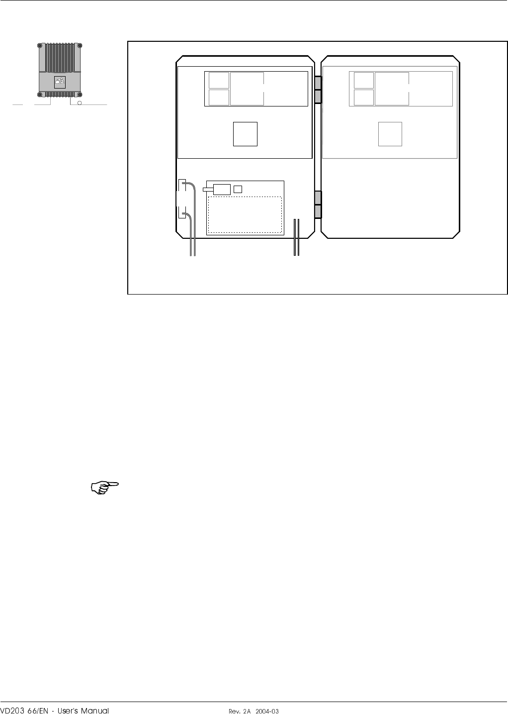
Sub Units in a BMU
A cabinet (the left part in Figure 5-6) for a BMU has no control unit
board and no amplifier boards but a Fiber Optic Unit (FOU) with a Fiber
Optic Node board (FON) or a Fiber Optic Transceiver (FOT) and a duplex
filter (DPX).
By adding WDMs and OSPs to the FOU (not shown in Figure 5-6), up to
four FORs can be fed in parallel by a BMU with double or single fiber
communication.
The cover (the right part in Figure 5-6) can be equipped as well, which
gives up to eight fiber optic FOR ports.
This repeater type has the opposite position of the BS connection (BTS)
compared to the other repeater types.
Sub units:
DC Directional Coupler.
DPX Duplex filter.
FON Fiber Optic Node board.
FOT Fiber Optic Transceiver board.
FOU Fiber Optic Unit.
PSU Power Supply Unit.
RIA Repeater to Repeater Interface Adapter board (optional).
RCC Remote Communication Control unit (optional). Only if a FON board
is used (the FOT board does not support the RCC unit).
The Repeater to Repeater Interface Adapter (RIA board) cannot be used
in the BMU, but the FON board has the R2R and F2F functionality
built-in. The FON board is described on page 5-46.
ALLGON
RF
PSU
DC
BS
BTS FOR
FON / FOT
DPX
FOU
DPX
FON / FOT
FOU
(RCC)
BTS = To base station antenna output and antenna (RF) FOR = To FOR (fiber optic)
Figure 5-6. Sub units in a BMU
LGP Allgon AB H|H#H ¦o6cro#fH6c|cro
Sau

Sub Units in an RMU
Figure 5-7 shows an example of an RMU for band selective operation.
This unit has the same FOU as the previous example, i.e. a Fiber Optic
Node board (FON) or a Fiber Optic Transceiver (FOT) and a duplex filter
(DPX). The FOU is mounted in the same band selective repeater that is
described on page 5-11. Only the MS Directional Coupler (DC-MS) is
omitted or not used.
Four or eight fiber optic ports can be obtained in the same way as
described in the previous example.
Sub units:
ALI Alarm Interface board.
BSA Band Selective Amplifier board.
CU Control Unit board.
DC Directional Coupler.
DPX Duplex filter.
FON Fiber Optic Node board.
FOT Fiber Optic Transceiver board.
FOU Fiber Optic Unit.
LNA Low Noise Amplifier.
PA Power Amplifier board.
PSU Power Supply Unit.
RIA Repeater to Repeater Interface Adapter board (optional).
r RCU Remote Control Unit (optional).
r RCC Remote Communication Control unit (optional). Only if a FON
board is used (the FOT board does not support the RCC unit).
The FON board has also the R2R and F2F functionality built-in. The
FON board is described on page 5-46.
ALLGON
LNA - DL
1234
LNA - UL
PSU
(RCU / RCC)
DPX
MS
(RIA)
CUALI
DC
BS
DPX
BS
BSA
DL PA
DL BSA
UL PA
UL
BS
5678
PSU
BSA
DL PA
DL BSA
UL PA
UL
FOR
FOU
FON / FOT
DPX
FOR = To FOR (fiber optic) BS = To base station antenna
Figure 5-7. Sub units in an RMU
¦o6cro#fH6c|cro H|H#H LGP Allgon AB
SauV

Sub Units in a FOR
Figure 5-8 shows an example of a FOR for band selective operation.
This unit has the same FOU as the previous examples, i.e. a Fiber Optic
Node board (FON) or a Fiber Optic Transceiver (FOT) and a duplex filter
(DPX). The FOU is mounted in the same band selective repeater that is
described on page 5-11. Only the BS Directional Coupler (DC-BS) is
omitted or not used.
By adding WDMs and OSPs to the FOU (not shown in Figure 5-8), a fiber
optic port for another FOR can be obtained with double or single fiber
communication.
Sub units:
ALI Alarm Interface board.
BSA Band Selective Amplifier board.
CU Control Unit board.
DC Directional Coupler.
DPX Duplex filter.
FON Fiber Optic Node board.
FOU Fiber Optic Unit.
LNA Low Noise Amplifier.
PA Power Amplifier board.
PSU Power Supply Unit.
RIA Repeater to Repeater Interface Adapter board (optional).
r RCU Remote Control Unit (optional).
r RCC Remote Communication Control unit (optional). Only if a FON
board is used (the FOT board does not support the RCC unit).
The FON board has also the R2R and F2F functionality built-in. The
FON board is described on page 5-46.
ALLGON
LNA - DL
1234
LNA - UL
PSU
(RCU / RCC)
DPX
MS
(RIA)
CUALI
DPX
BS
BSA
DL PA
DL BSA
UL PA
UL
5678
PSU
BSA
DL PA
DL BSA
UL PA
UL
FOU
FON / FOT
DPX
MS
BMU/RMU/FOR
DC
BS
MS = To mobile station antenna BMU/RMU/FOR = From BMU, RMU or FOR (fiber optic)
Figure 5-8. Sub units in a FOR
LGP Allgon AB H|H#H ¦o6cro#fH6c|cro
SauS

Block Diagram
The following block diagrams are found in this section:
•Channel selective GSM repeater, page 5-18.
•Channel selective CDMA/WCDMA repeater, page 5-20.
•Band selective repeater, page 5-22.
•BMU, page 5-24.
•RMU, page 5-26.
•FOR, page 5-28.
The main signal paths for the repeater types are described in general in
the next section and detailed under each block diagram.
Alarms are described on page 5-31.
Repeater setup is described on page 5-31.
¦o6cro#fH6c|cro H|H#H LGP Allgon AB
Sau

Downlink Signal Path
The downlink signal path, i.e. from the base station through the repeater
to the mobile station, is described for each repeater type under the block
diagrams on the following pages.
Uplink Signal Path
The uplink signal path, i.e. from the mobile station through the repeater
to the base station, is identical to the downlink path but the other way
round. Only some levels and component values differ.
The high power CDMA repeater has, however, a booster amplifier in the
downlink path.
LGP Allgon AB H|H#H ¦o6cro#fH6c|cro
Sau
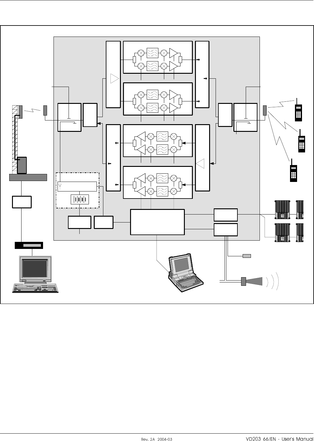
Channel Selective GSM Repeater
Figure 5-9 shows a block diagram of a channel selective repeater with four
bi-directional channels.
This diagram is applicable to repeaters for the GSM, DCS, PCN and
GSM 1900 (PCS) systems.
DC
BS
P31 P33
TEST -30 dB
DC
MS
TEST -30 dB
CHA1 - DL
CHA2 - DL
CHA3 - UL
CHA4 - UL
DPX
BS
LNA
DL CMB
DL
MS –20 dB
DPX
MS
ALI
RIA
CU
P34
ALLGON
ALLGON
ALL
ALL
P27 P32
ANT DPX ANT HI
LO
HI
LO
IN
OUT2
OUT1
P101 P701
P101 P701
ANT DPX ANT
P101
P101
P701
P701
LNA
UL
IN
OUT1
OUT2
CMB
UL
MS –20 dB
RCU
PSU ALI
MSC
CHANNEL
SELECTIVE
GSM REPEATER
BS antenna
Base station
Telephone
line
Modem
RF modem
External alarm sensors
MS antenna
R2R net
Figure 5-9. Block diagram, GSM repeater
¦o6cro#fH6c|cro H|H#H LGP Allgon AB
SauI

Downlink signal path
The signal from the base station is received via the repeater BS antenna
and is then forwarded through a directional coupler (DC). The signal
passes a duplex filter (DPX), is amplified in a low noise amplifier (LNA),
and enters the channel boards (CHA), which have two parallel channels
each.
The first mixer stage on the CHA amplifier board, which is controlled by
a synthesizer, converts the received frequency down to the IF frequency.
The signal is then filtered by SAW bandpass filters and, not shown in the
figure, amplified before it is fed to the second mixer stage for conversion
back to the original frequency.
The output signal from the mixer is then amplified in the power amplifier
and fed to a combiner, which combines the signals from the two channels
on the channel board.
The output signal passes a combiner (CMB), a duplex filter (DPX), and a
directional coupler (DC), before it is fed to the repeater MS antenna.
RCU is described on page 5-30.
R2R is described on page 5-30.
LGP Allgon AB H|H#H ¦o6cro#fH6c|cro
Saup
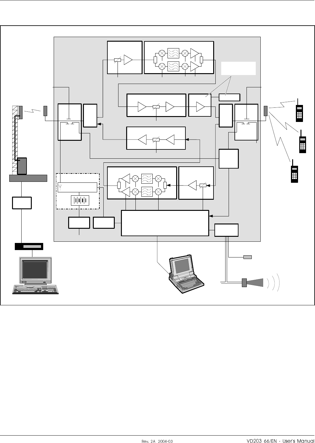
Channel Selective CDMA/WCDMA Repeater
Figure 5-10 shows a block diagram of a channel selective CDMA or
WCDMA repeater.
MS –20dB MS –20dB
DC
BS
P32
P31 P33
TEST -30 dB
DC
MS
TEST -30 dB
PA - DL
LNA - DL
PA - UL
LNA - UL
CSA - DL
DPX
MS
CSA - UL
ALI
P27
PSU2
DPX
BS
BA
ANT DPX HI
LO
ANT ANTDPX
ANT
HI
LO
IN OUT2 P101 P301
P4 P5 P3 P4
IN
OUT1
P101
P301
P4P5
MRX MRX
CU
MRX
P102
P101
MS –20 dB MS –20 dB
RCU
ALI
PSU1
MSC
CHANNEL
SELECTIVE
CDMA/WCDMA
REPEATER
BS antenna
Base station
Telephone
line
Modem
RF modem
External alarm sensors
MS antenna
High power
repeater only
Figure 5-10. Block diagram, CDMA/WCDMA repeater
¦o6cro#fH6c|cro H|H#H LGP Allgon AB
Sa¤®

Downlink signal path
The signal from the base station is received via the repeater BS antenna
and is then forwarded through a directional coupler (DC). The signal
passes a duplex filter (DPX), is amplified in a low noise amplifier (LNA),
and enters the channel board (CSA), which has two parallel channels.
The first mixer stage on the CSA amplifier board, which is controlled by a
synthesizer, converts the received frequency down to the IF frequency.
The signal is then filtered by SAW bandpass filters and, not shown in the
figure, amplified before it is fed to the second mixer stage for conversion
back to the original frequency.
The following amplifier on the CSA board is controlled by the CU unit.
The output gain can be reduced to avoid instability due to poor antenna
isolation by means of the gain control in the MRX unit. The MRX gain
control affects also other amplification stages.
The output signal from the amplifier is fed to a combiner that combines
the signals from the two channels on the CSA board.
The signal from the CSA board is amplified on the PA board and then fed
to a duplex filter (DPX) or, in high power CDMA repeaters, to a booster
amplifier board (BA).
The amplified output signal passes the duplex filter (DPX) and a
directional coupler (DC) before it is fed to the repeater MS antenna.
High power CDMA/WCDMA repeaters
In high power CDMA or WCDMA repeaters, a booster amplifier (BA)
boosts the output downlink signal from the PA board by typically 6dB.
The amplified signal is fed to the duplex filter (DPX).
Only the downlink path in high power CDMA repeaters has a BA booster
amplifier.
The BA amplifier is powered by a separate power supply unit (PSU2).
CDMA repeaters with MRX
In CDMA repeaters, the output and input signals are measured at the MS
and BS directional couplers (DC) by means of the MRX unit. The MRX
unit continuously supervises the signal levels and controls the output gain
levels via the CU unit to avoid self oscillation due to permanently or
temporarily decreased antenna isolation.
The MRX unit offers also spectrum analyzis features further described in
the OMT32, User’s Manual.
RCU is described on page 5-30.
LGP Allgon AB H|H#H ¦o6cro#fH6c|cro
Sa¤u
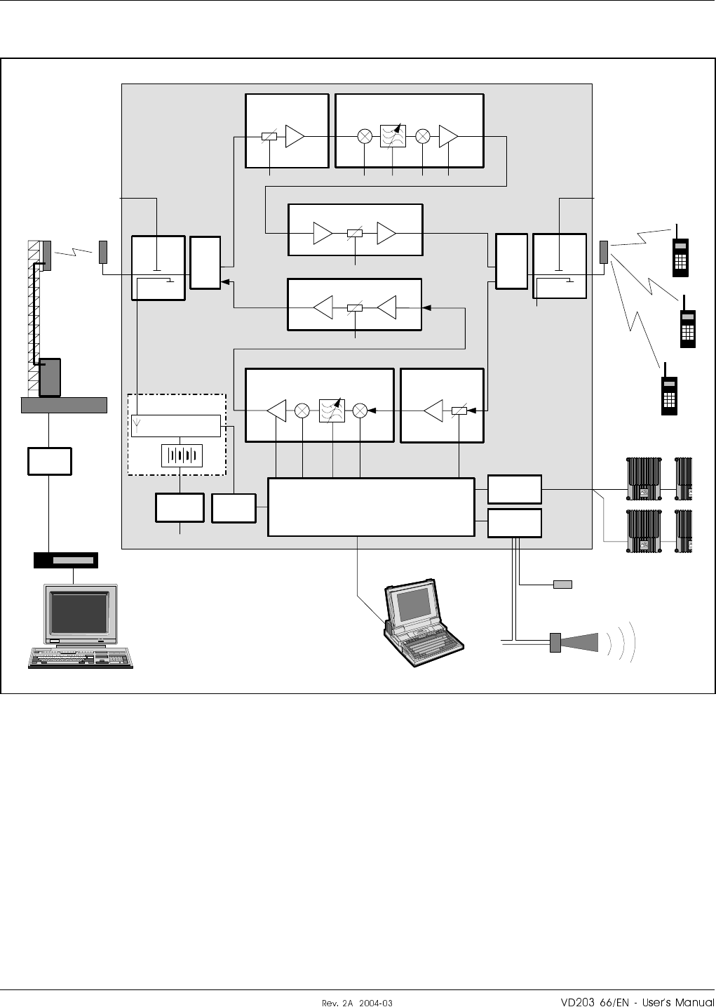
Band Selective Repeater
Figure 5-11 shows a block diagram of a band selective repeater.
This diagram is applicable to repeaters for e.g. NMT, GSM, TACS,
ETACS, AMPS, DAMPS, CDMA and WCDMA systems.
DC
BS
P32
P31 P33
TEST -30 dB
DC
MS
TEST -30 dB
BSA - DL
PA - DL
LNA - DL
MS –20 dB PA - UL
BSA - UL LNA - UL
DPX
MS
DPX
BS
ALI
RIA P34
CU
ALLGON
ALLGON
ALL
ALL
P27
ANT DPX ANTHI
LO
ANTDPX
ANT
HI
LO
IN OUT2 P101 P301
P4 P5
IN
IN
OUT1
P301 P101
P4P5
MS –20 dB
RCU
PSU ALI
MSC
BAND
SELECTIVE
REPEATER
BS antenna
Base station
Telephone
line
Modem
RF modem
External alarm sensors
MS antenna
R2R net
Figure 5-11. Block diagram, band selective repeater
¦o6cro#fH6c|cro H|H#H LGP Allgon AB
Sa¤¤

Downlink signal path
The signal from the base station is received via the repeater BS antenna
and is then forwarded through a directional coupler (DC). The signal
passes a duplex filter (DPX), is amplified in a low noise amplifier (LNA),
and enters the band selective amplifier board (BSA).
The first mixer stage on the BSA amplifier board, which is controlled by a
synthesizer, converts the received frequency down to the IF frequency.
The signal is then filtered by SAW bandpass filters and, not shown in the
figure, amplified before it is fed to the second mixer stage for conversion
back to the original frequency.
The BSA board has adjustable bandwidth and the SAW filter combination
can be software changed from OMT32 (or OMS).
The following power amplifier is controlled by the CU unit. The amplifier
gain will be reduced to avoid instability due to poor antenna isolation.
A detector on the PA board measures continuously the output level. The
signal from this detector is used by the automatic gain control, AGC, to
supervise and, if necessary, reduce the output power to keep it under a
maximum level. The AGC gain control affects also other amplification
stages.
The output signal passes duplex filter (DPX) and a directional coupler
(DC) before it is fed to the repeater MS antenna.
RCU is described on page 5-30.
R2R is described on page 5-30.
LGP Allgon AB H|H#H ¦o6cro#fH6c|cro
Sa¤
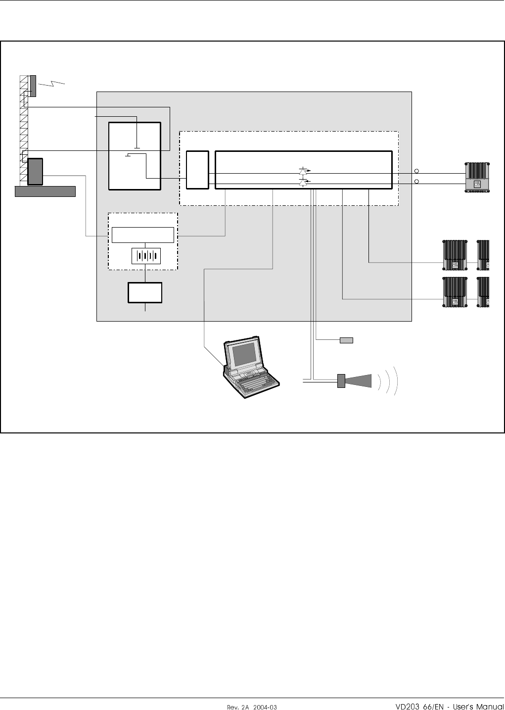
BMU
Figure 5-12 shows a block diagram of a BMU.
The BMU has to be located adjacent to the BTS as the base station
antenna signal passes through the BMU.
Features controlled by the CU, ALI and RIA boards in standard repeaters
are here controlled by the FON board that has the required functionality
built-in. It also has the F2F function built-in (+F2F in Figure 5-12).
The FON board is described on page 5-46.
A FOT board can be used instead of a FON board, but the RCC, external
alarm and R2R net functions are not supported by the FOT board.
The FON board is described below.
DC
BS
TEST -30 dB
MS –20 dB
ANT DPX
FON
TX
RX
DPX
ANT HI
LO
FOU
FOR
ALLGON
BTS
P27
RCC
PSU
P111
ALLGON
ALLGON
ALL
ALL
P112P130 P109P106
P101
P102
+F2F
BMU
Modem
R2R net
External alarm sensors
Figure 5-12. Block diagram, BMU
¦o6cro#fH6c|cro H|H#H LGP Allgon AB
Sa¤V

Downlink signal path
The base station antenna signal is fed through a directional coupler (DC)
inside the BMU. The signal from the MS –20dB port enters the FOU by
passing a duplex filter (DPX).
The downlink path (HI) is then fed to the FON board that converts the
RF signal to an optic signal.
The optic signal from the TX output is sent via fiber optic cables to a FOR.
RCC is described on page 5-30.
R2R is described on page 5-30.
F2F is described on page 5-31.
LGP Allgon AB H|H#H ¦o6cro#fH6c|cro
Sa¤S
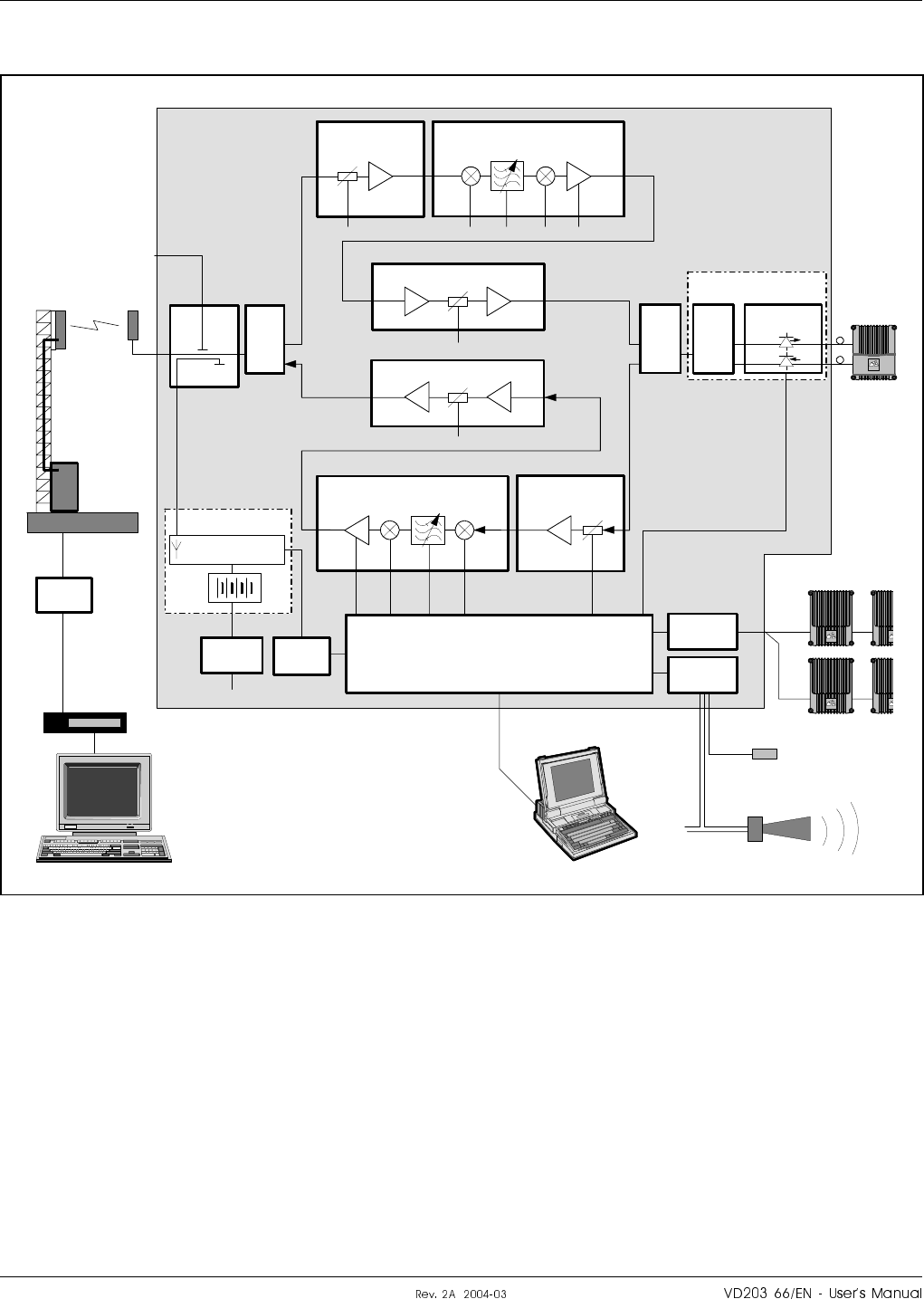
RMU
Figure 5-13 shows a block diagram of an RMU for band selective
operation.
This diagram is identical to the block diagram of the band selective
repeater on page 5-22, except for the FOU and the fiber optic connection
to the FOR.
A FOT board can be used instead of the FON board, but the F2F function
is not supported by the FOT board (+F2F in Figure 5-13).
An RCC unit can be used instead of the RCU shown in Figure 5-13,
provided a FON board is used. The RCC is then connected to the FON
board. The FOT board does not support the RCC unit.
MSC
DC
BS
P32
P31 P33
TEST -30 dB
BSA - DL
PA - DL
LNA - DL
MS –20 dB PA - UL
BSA - UL LNA - UL
DPX
MS
DPX
BS
ALI
RIA P34
ALLGON
ALLGON
ALL
ALL
P27
ANT DPX ANTHI
LO ANT
HI
LO
IN OUT2 P101 P301
P4 P5
IN
IN
OUT1
P301 P101
P4P5
RCU
PSU ALI
FON / FOT
P101 TX
RX
P102
DPX
ANT HI
LO
FOU
FOR
ALLGON
CU
+F2F
RMU
BS antenna
Base station
Telephone
line
Modem
RF modem
External alarm sensors
R2R net
Figure 5-13. Block diagram, RMU
¦o6cro#fH6c|cro H|H#H LGP Allgon AB
Sa¤

Downlink signal path
The signal from the duplex filter (DPX-MS) enters the FOU by passing a
duplex filter (DPX).
The downlink path (HI) is then fed to the FON board that converts the
RF signal to an optic signal.
The FON board supervises the signaling and reports errors to the CU.
The optic signal from the TX output is sent via a fiber optic cable to a
FOR.
RCU is described on page 5-30.
RCC is described on page 5-30.
R2R is described on page 5-30.
F2F is described on page 5-31.
LGP Allgon AB H|H#H ¦o6cro#fH6c|cro
Sa¤
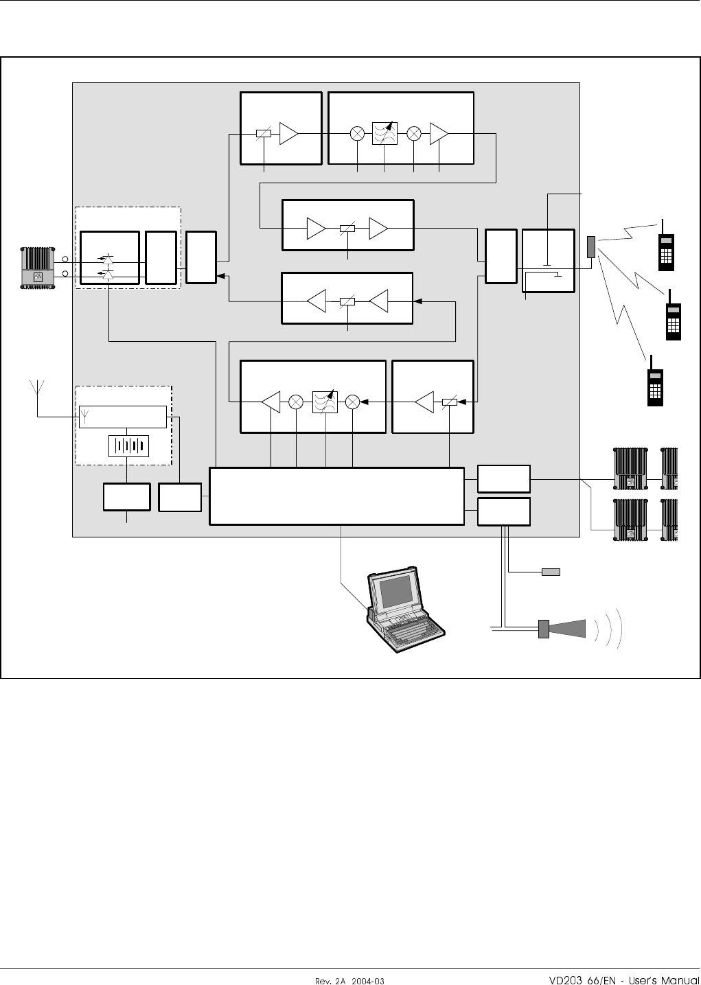
FOR
Figure 5-14 shows a block diagram of a FOR with band selective operation.
The diagram is identical to the block diagram of the band selective
repeater on page 5-22, except for the FOU and the fiber optic connection
to the BMU, RMU or FOR.
A FOT board can be used instead of the FON board, but the F2F function
is not supported by the FOT board (+F2F in Figure 5-14).
An RCC unit can be used instead of the RCU shown in Figure 5-13,
provided a FON board is used. The RCC is then connected to the FON
board. The FOT board does not support the RCC unit.
P32
P31 P33
DC
MS
TEST -30 dB
BSA - DL
PA - DL
LNA - DL
PA - UL
BSA - UL LNA - UL
DPX
MS
ALI
RIA P34
CU
ALLGON
ALLGON
ALL
ALL
P27
ANTDPX
ANT
HI
LO
IN OUT2 P101 P301
P4 P5
IN
IN
OUT1
P301 P101
P4P5
MS –20 dB
RCU
PSU ALI
FOU
BMU/
RMU/
FOR
FON / FOR
P102RX
TX P101
ALLGON
DPX
BS
ANT HI
LO
DPX
ANT
HI
LO
+F2F
FOR
RF modem
External alarm sensors
R2R net
MS antenna
Figure 5-14. Block diagram, FOR
¦o6cro#fH6c|cro H|H#H LGP Allgon AB
Sa¤I

Downlink signal path
The signal from a BMU, RMU or FOR is received via a fiber optic cable
and is fed to the FON board on the FOU.
The FON board converts the optic signal to an RF signal.
The FON board supervises also the signaling and reports errors to the CU.
The RF signal passes first a duplex filter (DPX) and then the standard
duplex filter (DPX-BS) in the band selective repeater.
RCU is described on page 5-30.
RCC is described on page 5-30.
R2R is described on page 5-30.
F2F is described on page 5-31.
LGP Allgon AB H|H#H ¦o6cro#fH6c|cro
Sa¤p

RCU
The optional RCU Remote Control Unit is located inside the repeater
(described in Chapter 6, Optionals).
Communication with the repeater is performed by means of a GSM
modem that has the antenna connected to the BS directional coupler (DC)
or has a separate antenna. Data is transferred between the repeater and
the RCU via the P32 modem port.
The RCU unit is powered via the P27 auxiliary port and the unit has a
battery with a capacity enough for sending a number of alarms if a mains
power failure occurs.
RCC
The optional RCC Remote Communication Control unit is an alternative
to the RCU, provided the repeater has a FON board. The RCC unit is also
used in the Compact repeaters.
An RCC unit is required if the communication unit has to be connected to
a FON board, e.g. in the BMU (the FON board does not support the RCU).
Communication with the repeater is performed by means of a PSTN or
RF modem that has the antenna connected to the BS directional coupler
(DC) or has a separate antenna. Data is transferred between the repeater
and the RCC unit via the P130 port on the FON board.
The RCC unit is also powered via the P130 port and the unit has a
battery with capacity enough for sending a number of alarms if a mains
power failure occurs.
A description of the RCC and its connection is found in the VD203 67/EN,
ALR Compact Repeater, User’s Manual.
R2R
The optional R2R Repeater to Repeater Link feature makes it possible to
communicate with a number of repeaters via one RCU unit in one of the
repeaters in an R2R net. Several RCU units can also be used in the same
net.
The repeaters in the R2R net are connected to the P34 port.
The R2R feature is described in Chapter 6, Optionals.
¦o6cro#fH6c|cro H|H#H LGP Allgon AB
Sa®

F2F
The F2F feature makes it possible to communicate with all repeaters that
have a FON board (i.e. BMU, RMU and FOR) and are included in the
same fiber optic net. By using the existing fiber optic distribution net, no
wire or other communication device is required.
Communication with repeaters in a mixed F2F and R2R net is possible.
Alarm
Alarm signals from external sensors are received by the ALI board, which
forwards the alarm signals to the CU board.
The software on the CU board is able to activate acoustic or visual alarm
or direct the alarm to the P33 alarm port to be forwarded, via the RCU
unit, to OMT32 (or OMS) located in an operation and maintenance
central.
Alarms can also be handled by the FON board in fiber optic units, e.g. the
BMU that has no CU board or ALI board.
Alarms can be configured from OMT32 (or OMS).
Repeater Setup
The repeater parameters can be set locally by means of a desktop or
notebook running OMT32.
The PC is connected to the CU via the P31 PC port. See the block
diagrams (e.g. Figure 5-9 on page 5-18).
If the repeater has no CU unit but a FON board (e.g. the BMU), then the
desktop or notebook is connected to the P106 port on the FON board (see
Figure 5-12 on page 5-24).
If the repeater has an RCU or RCC, then the repeater parameters can be
set remotely by means of a desktop or notebook running OMT32 or OMS
and a modem.
LGP Allgon AB H|H#H ¦o6cro#fH6c|cro
Sau

Board and Unit Descriptions
This section describes the main boards and units in the AR repeaters.
Information about cabling between boards and units is found on page 5-57.
The following amplifier boards and units are described in this section:
•CHA – Channel Amplifier board, page 5-33.
•CSA & PA – Channel Selective CDMA/WCDMA boards, page 5-34.
•BA – Booster Amplifier board for high power CDMA/WCDMA, page 5-35.
•BSA & PA – Band Selective boards, page 5-36.
•DIA – Distribution board, page 5-37.
•CU – Control Unit board, page 5-39.
•MRX – Measurement Receiver board, page 5-40.
•DC – Directional Coupler, page 5-42.
•LNA – Low Noise Amplifier, page 5-43.
•DPX – Duplex filter, page 5-44.
•FOU – Fiber Optic Unit, page 5-45.
•FON – Fiber Optic Node board, page 5-46.
•FOT – Fiber Optic Transceiver board, page 5-50.
¦o6cro#fH6c|cro H|H#H LGP Allgon AB
Sa¤
CHA – Channel Amplifier Board
The cabinet can be equipped with four CHA Channel Amplifier boards.
These are numbered from left to right: CHA1 – CHA4. The board
positions CHA1 – CHA2 are used for downlink and CHA3 – CHA4 for
uplink (see Figure 5-1 on page 5-8). If the repeater is equipped with two
channels only, the board positions 1 and 3 are used.
The two internal channels on each CHA board are located to the left and
to the right on the board.
If a board is to be removed, the RFI filter at the board connector and the
two coaxial connectors must be removed prior to the board removal. No
heat compound is used on the heat sink body or on the chassis.
Coaxial connector P101 is the input of the CHA board (fed by LNA).
Coaxial connector P701 is the output of the board. The output signal is
fed to the duplex filter, either directly or via a CMB combiner, depending
on the repeater configuration.
Connection
CHA1/DL (board #1 from left).
Port Connected to
P101 OUT2 on the LNA/DL low noise amplifier.
P701 4 channels: Input on the CMB/DL combiner.
2 channels: HI on the DPX/MS duplex filter.
CHA2/DL (board #2 from left).
Port Connected to
P101 OUT1 on the LNA/DL low noise amplifier.
P701 Input on the CMB/DL combiner.
CHA3/UL (board #3 from left).
Port Connected to
P101 OUT1 on the LNA/UL low noise amplifier.
P701 4 channels: Input on the CMB/UL combiner.
2 channels: LO on the DPX/BS duplex filter.
CHA4/UL (board #4 from left).
Port Connected to
P101 OUT2 on the LNA/UL low noise amplifier.
P701 Input on the CMB/UL combiner.
Caution
!
The CHA Channel Amplifier board power transistors may contain
beryllium oxide (BeO) that is poisonous. See Chapter 1, Safety.
LGP Allgon AB H|H#H ¦o6cro#fH6c|cro
Sa
CSA & PA – Channel Selective CDMA/WCDMA Boards
For channel selective CDMA or WCDMA operation, the cabinet is
normally equipped with two CSA and two PA boards. These are numbered
from left to right. Board position 1 is used for CSA downlink board,
position 2 for PA downlink board, position 3 for CSA uplink board, and
position 4 for PA uplink board (see Figure 5-2 on page 5-9).
If a board is to be removed, the RFI filter at the board connector, the two
coaxial connectors, and the flat conductor cable between the CSA board
and the PA board must be removed prior to the board removal. No heat
compound is used on the heat sink body or on the chassis.
Coaxial connector P101 is the input of the CSA board (fed by LNA).
Coaxial connector P301 is the output of the CSA board. The signal from
this output is fed to the PA board input P4. The PA board output P5 is
fed to the duplex filter of the same signal direction.
Connection
CSA/DL (board #1 from left).
Port Connected to
P101 OUT1 on the LNA/DL low noise amplifier.
P301 P4 on the PA/DL board.
PA/DL (board #2 from left).
Port Connected to
P4 P301 on the CSA/DL board.
P5 Channel selective high power CDMA/WCDMA repeater:
P3 on the BA/DL board in the cover.
All other types: HI on the DPX/MS duplex filter.
CSA/UL (board #3 from left).
Port Connected to
P101 OUT1 on the LNA/UL low noise amplifier.
P301 P4 on the PA/UL board.
PA/UL (board #4 from left).
Port Connected to
P4 P301 on the CSA/UL board.
P5 LO on the DPX/BS duplex filter.
Caution
!
The PA Power Amplifier board power transistors may contain beryllium
oxide (BeO) that is poisonous. See Chapter 1, Safety.
¦o6cro#fH6c|cro H|H#H LGP Allgon AB
SaV
BA – Booster Amplifier for High Power CDMA/WCDMA
For CDMA and WCDMA repeaters, a BA (Booster Amplifier) can be added
in the downlink path to increase the output power with typically 6dB.
A high power CDMA or WCDMA repeater with a BA board can operate
with maximum 2 channels.
The BA board is shown in the block diagram on page 5-20. It occupies
board position 7 in the cover (see the repeater units on page 5-10).
A second power supply unit (PSU2), located in the repeater cover, is
required for the BA board. This PSU is a special PSU for the BA board.
The BA booster amplifier requires a heat sink applied on the front of the
repeater.
If the BA board is to be removed, the RFI filter at the board connector
and the two coaxial connectors must be removed prior to the board
removal. No heat compound is used on the heat sink body or on the
chassis.
Coaxial connector P3 is the amplifier input (fed by the downlink PA
board).
Coaxial connector P4 is the amplifier output. The signal from this output
is fed, via the downlink duplex filter and directional coupler, to the
downlink antenna.
Connection
BA/DL
Port Connected to
P3 P5 on the PA/DL board.
P4 HI on the DPX/MS duplex filter.
LGP Allgon AB H|H#H ¦o6cro#fH6c|cro
SaS
BSA & PA – Band Selective Boards
For band selective operation, the cabinet is equipped with two BSA and
two PA boards. These are numbered from left to right. Board position 1 is
used for BSA downlink board, position 2 for PA downlink board,
position 3 for BSA uplink board, and position 4 for PA downlink board
(see Figure 5-4 on page 5-11).
If a board is to be removed, the RFI filter at the board connector, the two
coaxial connectors, and the flat conductor cable between the BSA board
and the PA board must be removed prior to the board removal. No heat
compound is used on the heat sink body or on the chassis.
Coaxial connector P101 is the input of the BSA board (fed by LNA).
Coaxial connector P301 is the output of the BSA board. The signal from
this output is fed to the PA board input P4. The PA board output P5 is
fed to the duplex filter of the same signal direction.
Connection
BSA/DL (board #1 from left).
Port Connected to
P101 OUT1 on the LNA/DL low noise amplifier.
P301 P4 on the PA/DL board.
PA/DL (board #2 from left).
Port Connected to
P4 P301 on the BSA/DL board.
P5 HI on the DPX/MS duplex filter.
BSA/UL (board #3 from left).
Port Connected to
P101 OUT1 on the LNA/UL low noise amplifier.
P301 P4 on the PA/UL board.
PA/UL (board #4 from left).
Port Connected to
P4 P301 on the BSA/UL board.
P5 LO on the DPX/BS duplex filter.
Caution
!
The PA Power Amplifier board power transistors may contain beryllium
oxide (BeO) that is poisonous. See Chapter 1, Safety.
¦o6cro#fH6c|cro H|H#H LGP Allgon AB
Sa
DIA – Distribution Board
DIA is a distribution board for most of the boards, units and ports. The
DIA board is exclusively equipped with connectors. The connector types
are chosen to prevent unintentional mixing up.
Connection and connector types
Port Connected to Connector type
P2 CU board.
P3 Not used.
P4 ALI board.
P5 Not used.
P11 CHA1/DL or CSA/DL or BSA/DL. 16 pole 1 line female.
P12 CHA2/DL or PA/DL. 16 pole 1 line female.
P13 CHA3/UL or CSA/UL or BSA/UL. 16 pole 1 line female.
P14 CHA4/UL or PA/UL. 16 pole 1 line female.
P21 PSU - Power Supply Unit. 10 pole 2 line male.
P22 LED board in the cover. 4 pole 1 line male.
P23 LNA/UL 2 pole 1 line male.
P24 LNA/DL 2 pole 1 line male.
P25 Expansion output port to cover
circuitry if any. Only in cabinets. 16 pole 2 line male.
P26 Expansion input port from the
cabinet. Used in equipped high
covers only.
16 pole 2 line male.
*P27 AUX1 auxiliary connector. 8 pole 1 line male.
P28 Door switch (internal alarm). 3 pole 1 line male.
P31 PC (serial RS-232). 9 pole D-sub female.
P32 Modem (serial RS-232). 9 pole D-sub male.
P33 External alarm. 15 pole D-sub female.
P34 Repeater to Repeater Link. 8 pole RJ45 modular female.
*Pin 2 and 3 on the P27 connector must be interconnected with a jumper
if the connector is not used.
P28
P33
P26
P32
P23
P27
P5 P3
P4 P2
P11 P12 P13 P14
P21
P31
P22 P25
P24
U7A U7B U7C U26
U7D
U7E
U7F
GND
P34
Figure 5-15. DIA board connectors and testpoints
LGP Allgon AB H|H#H ¦o6cro#fH6c|cro
Sa
Testpoints
The following testpoints are found on the DIA board (see Figure 5-15).
Testpoint Voltage Purpose
U7A +7V DC CHA1/DL or CSA/DL or BSA/DL downlink
board supply voltage.
U7B +7V DC CHA2/DL or PA/DL downlink board supply
voltage.
U7C +7V DC CHA3/UL or CSA/UL or BSA/UL downlink
board supply voltage.
U7D +7V DC CHA4/UL or PA/UL downlink board supply
voltage.
U7E +7V DC LNA/UL and LNA/DL and P27 auxiliary port
supply voltage.
U7F +7V DC CU board and ALI board and RCU supply
voltage via the P27 auxiliary port jumper.
U26 +26V DC
or
+13V DC
Power amplifiers and P27 auxiliary port supply
voltage (26V or 13V depending on the repeater
type).
GND 0 Ground
DIA board part # and version
The DIA board part # is K105/1. Version R2A or higher (containing the
P34 connector) is required to use the optional R2R feature.
¦o6cro#fH6c|cro H|H#H LGP Allgon AB
SaI

CU – Control Unit Board
The CU board is the central board in the repeater, located in the repeater
cabinet (see Figure 5-1 to Figure 5-5). The CU board contains a
microprocessor, main memory, flash memory for the CU software,
EEPROM memory for parameters, memory for the event log and
statistics, a REFO reference oscillator, ports for local and remote
communication, battery powered real-time clock, etc.
The CU board is used to supervise and control operational parameters
such as gain control, channel handling, etc. The CU takes care of alarms
and the event log, password and logon, and many other procedures.
The CU is also a control interface when using OMT32, locally or remotely
via modem, or OMS.
The CU software can be downloaded from OMT32, either locally or
remotely, or from OMS.
The real-time clock on the CU board is used for alarm and for the event
log.
There are currently two CU board variants: K103/1 and K103/2.
CU board and CU software part #s
u®u,r#?~rf? CU board K103/1 can be run with the SA102 01/2 CU software. This
board can store one version of CU software. The repeater will always boot
on this software version.
u®¤,r#?~6¦Ho CU board K103/2 can be run with either the old SA102 01/2 CU software
or the current SA102 02/1 or SA102 02/2 CU software. This board can
store two versions of CU software, located in segment 1 and segment 2 of
the flash memory as Application 1 and Application 2. The repeater will
boot on that software which is set as Primary (description of Primary
application is found in the OMT32, User’s Manual).
Compatibility for CU boards and CU software is detailed on page 5-67.
Connection
The CU board is connected to the DIA board via the P2 port.
Caution
A lithium battery is permanently mounted on the CU board. Due to the
risk of explosion, this battery must not be removed from the board. In
case of battery malfunction, replace the CU board. The old CU board can
be sent to LGP Allgon for repair.
LGP Allgon AB H|H#H ¦o6cro#fH6c|cro
Sap
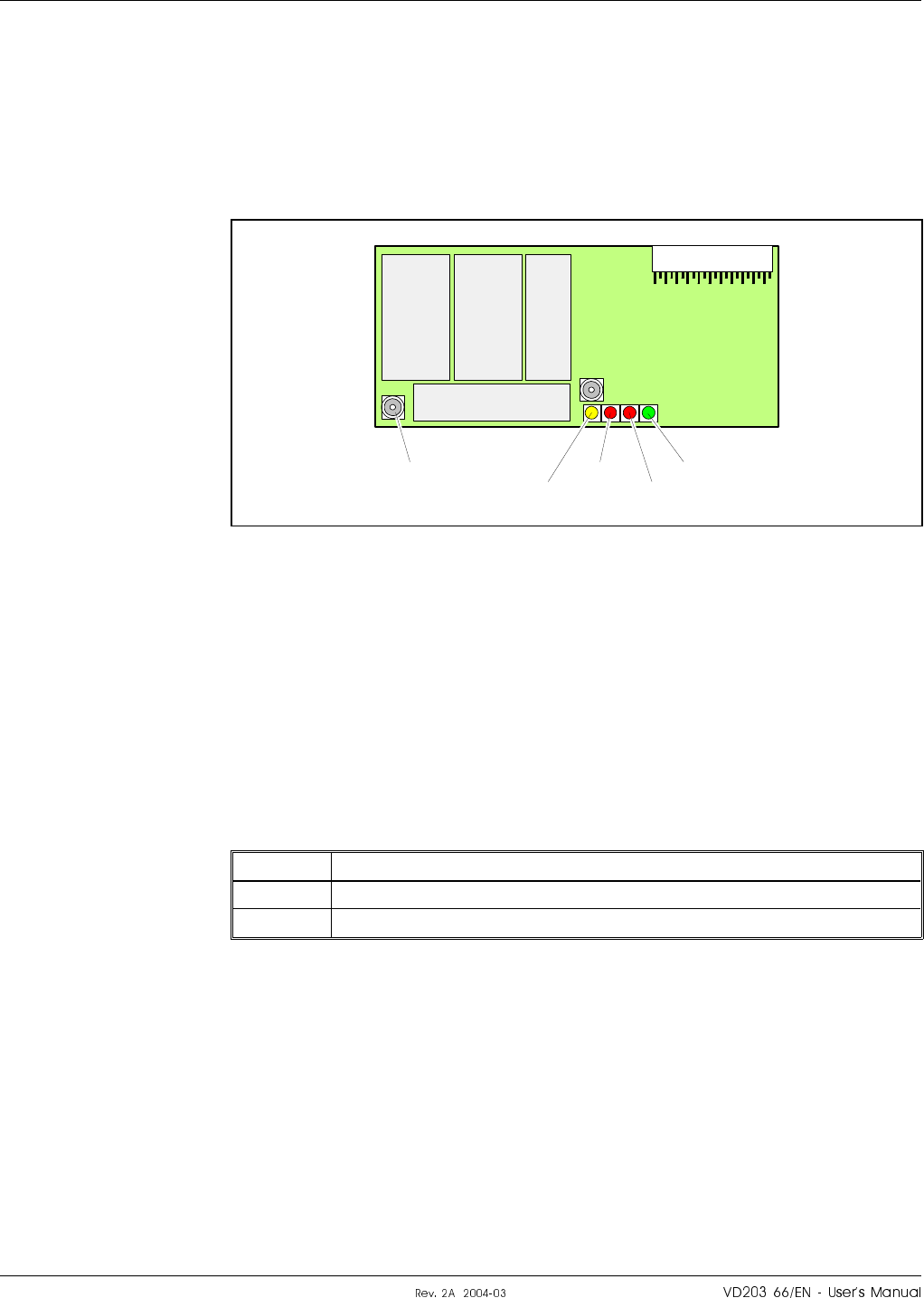
MRX – Measurement Receiver Board
Channel selective CDMA repeaters are equipped with an MRX
(Measurement Receiver) that continuously supervises the signal levels and
controls the output gain levels via the CU unit to avoid self oscillation due
to permanently or temporarily decreased antenna isolation.
The MRX board is shown in Figure 5-16.
The four LEDs (POWER, BOOT, FAULT and OPER) have the same
function as the CU unit, described in Chapter 4.
The MRX board is located in the frame on the DIA board, see the
repeater units on page 5-9 and page 5-10.
The MRX unit is also shown in the CDMA block diagram on page 5-20.
Connection
MRX
Port Connected to
P101 MRX on the DC/MS directional coupler.
P102 MRX on the DC/BS directional coupler.
MRX function
The main task of the MRX unit is to supervise the channel spectrum of
active CDMA channels in a channel selective CDMA 800/1900 repeater in
order to maximize gain and output power, and to minimize problems as
low antenna isolation and poor antenna matching.
The MRX unit also offers spectrum monitoring and return loss
measurement.
P102
P101
POWER
BOOT
FAULT
OPER
Figure 5-16. MRX Measurement Receiver board
¦o6cro#fH6c|cro H|H#H LGP Allgon AB
SaV®

Antenna isolation
The MRX unit automatically supervises the antenna isolation. The system
will detect both the margins to instability and full self-oscillation.
Two different alarm types (Warning and Ceasing) can be sent by the
MRX unit due to poor antenna isolation:
–If a low margin to instability is detected, then a Warning alarm is
sent and the gain is reduced gradually to a preset value.
–If the MRX unit detects self-oscillation, then a Warning alarm is sent
and the gain is reduced to the same preset value.
–When the MRX unit no longer senses any isolation problems a
Ceasing signal is sent and the gain is increased to the level set by the
operator.
Return loss (VSWR)
The MRX unit will automatically and continuously supervise both the
donor and the service antennas. The operator can, however, also manually
start a measurement of a desired antenna simply by selecting a CDMA
antenna, which will then be used for the measurement.
A Warning alarm is sent when the return loss is below an alarm
threshold that is set by the operator. When the return loss is above the
same threshold again, a Ceasing signal is sent.
Spectrum monitoring
This feature allows the operator to perform spectrum analyzis in local or
remote mode. This is further described in the OMT32, User’s Manual.
LGP Allgon AB H|H#H ¦o6cro#fH6c|cro
SaVu
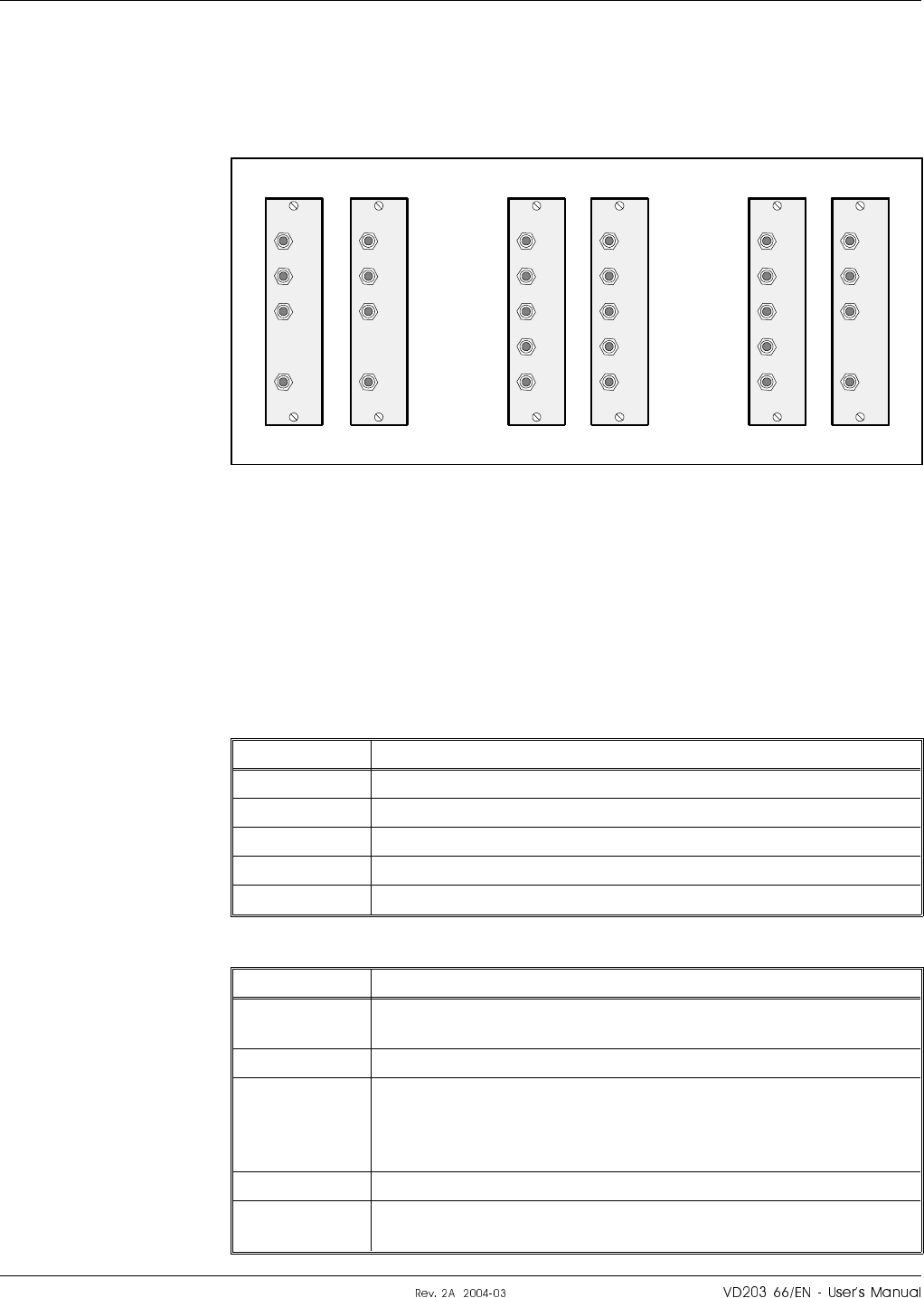
DC – Directional Coupler
The directional couplers are located at the left and right side in the lower
part of the repeater cabinet (see Figure 5-1 to Figure 5-5). The MS and
BS directional couplers are shown in Figure 5-17.
The following types are depicted in Figure 5-17:
STD Couplers for standard repeaters.
CDMA-MRX Couplers for CDMA repeaters with MRX.
HP-CDMA Couplers for high power CDMA/WCDMA repeaters.
Connection
DC/MS
Port Connected to
DPX ANT on the DPX/MS duplex filter.
TEST –30dB Test port for the downlink output signal (no directivity).
MS –20dB Not used.
MRX P101 on the MRX unit.
ANT MS antenna (or RF service cable).
DC/BS
Port Connected to
DPX BMU: BTS antenna (see page 5-64).
All other types: ANT on the DPX/BS duplex filter.
TEST –30dB Test port for the uplink output signal (no directivity).
BS –20dB BMU: ANT on the FOU/DPX duplex filter.
All other types:
Antenna connection for remote control RF modem. This
port has at least 20dB directivity towards the antenna.
MRX P102 on the MRX unit.
ANT BMU: BTS antenna output port (see page 5-64).
All other types: BS antenna (or RF cable to BTS).
MS
DPX
ANT
TEST
DC
-30 dB
-20 dB MRX
DPX
ANT
TEST
DC
-30 dB
MS
-20 dB
MRX
DPX
ANT
TEST
DC
-30 dB
BS
DPX
ANT
TEST
DC
-30 dB
-20 dB MRX
DPX
ANT
TEST
DC
-30 dB
BS
-20 dB
MS BS MS BS
STD CDMA-MRX
MRX
DPX
ANT
TEST
DC
-30 dB
BS
-20 dB
BS MS
HP-CDMA
Figure 5-17. MS and BS directional couplers
¦o6cro#fH6c|cro H|H#H LGP Allgon AB
SaV¤
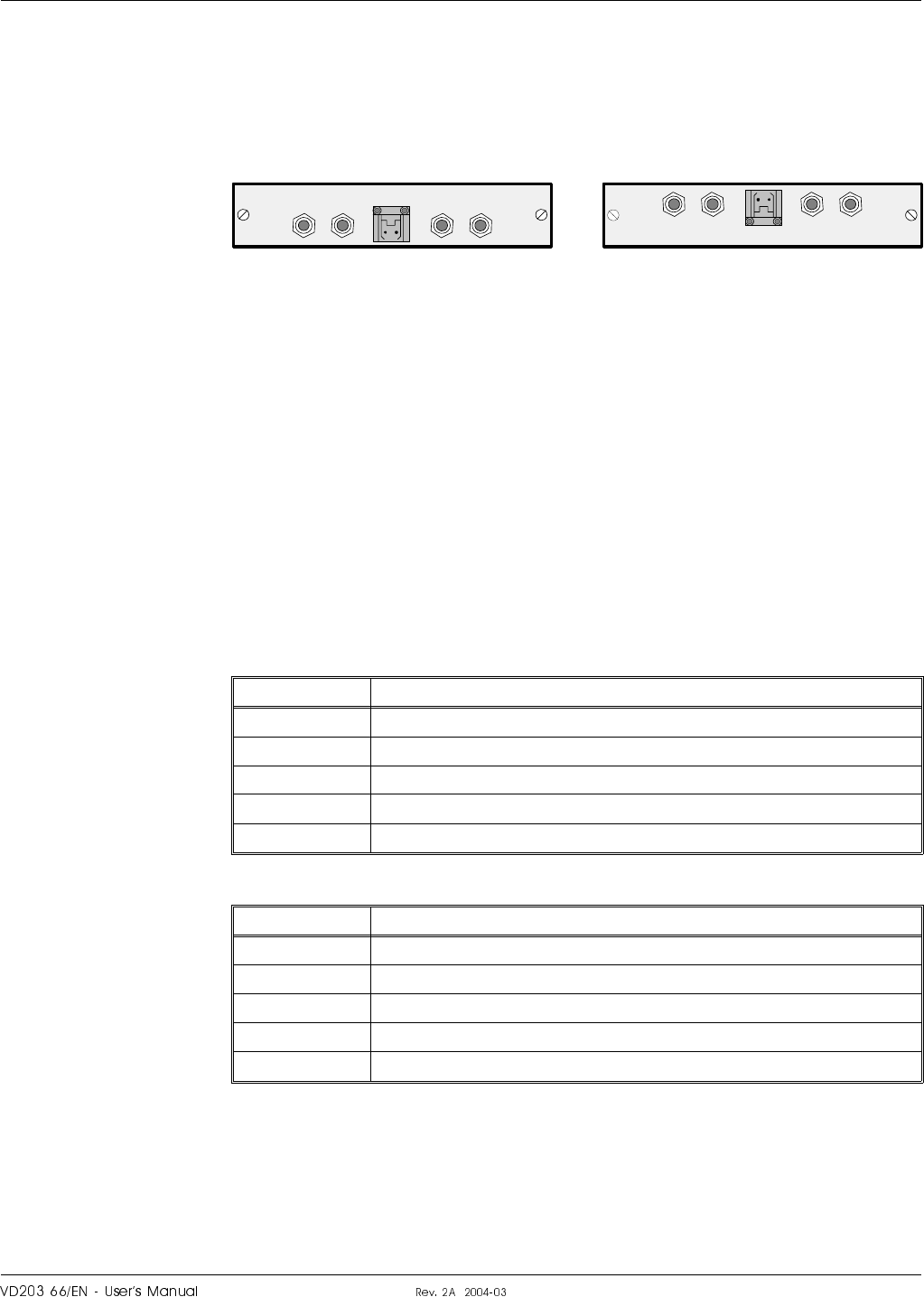
LNA – Low Noise Amplifier
The LNA low noise amplifiers are located at the top of the cabinet and
the high cover, if equipped (see Figure 5-1 to Figure 5-5). LNA/UL
(uplink) is located to the left and LNA/DL (downlink) to the right. All
coaxial connectors are of SMA type.
Signals from the duplex filter output are fed to the LNA input connector
IN. Output OUT1 and OUT2 feed the CHA, CSA or BSA boards of the
same signal direction. The signal level in these connectors are +20dB
referred to the antenna input. Another output, OUT LOW, is an
expansion output for an additional LNA amplifier, if the repeater is
equipped in the cover part of the chassis. The gain to this connector is
+2dB.
The +7V input is used for 7V supply from the DIA board.
ATT is a control signal for a controllable attenuator in the LNA.
Connection
LNA/UL (to the left in the cabinet or cover).
Port Connected to
OUT LOW IN on the LNA/UL in the cover, if equipped.
IN LO on the DPX/MS duplex filter.
ATT +7V P23 on the DIA board.
OUT1 P101 on the CHA3/UL or CSA/UL or BSA/UL board.
OUT2 P101 on the CHA4/UL channel board.
LNA/DL (to the right in the cabinet or cover).
Port Connected to
OUT LOW IN on the LNA/DL in the cover, if equipped.
IN HI on the DPX/BS duplex filter.
ATT +7V P24 on the DIA board.
OUT1 P101 on the CHA2/DL or CSA/DL, or BSA/DL board.
OUT2 P101 on the CHA1/DL channel board.
Not used outputs do not need to be terminated.
OUT
LOW
IN+7V ATTOUT2 OUT1
LNA
DL
OUT
LOW IN ATT +7V OUT1 OUT2
LNA
UL
Figure 5-18. LNA low noise amplifier
LGP Allgon AB H|H#H ¦o6cro#fH6c|cro
SaV
DPX – Duplex Filter
The DPX duplex filters are located on the metal cover sheet in the upper
part of the repeater cabinet (see Figure 5-1 to Figure 5-5). MS and BS
duplex filters are identical.
Connection
DPX/MS
Port Connected to
ANT RMU: ANT on the FOU/DPX duplex filter.
All other types: DPX on the DC/MS directional coupler.
HI Channel selective GSM repeater:
4 channels: Output on the CMB/DL combiner.
2 channels: P701 on the CHA1/DL channel board.
Channel selective CDMA/WCDMA repeater:
P5 on the PA/DL board.
Channel selective high power CDMA/WCDMA repeater:
P4 on the BA/DL board in the cover.
Band selective repeater:
P5 on the PA/DL board.
LO IN on the LNA/UL low noise amplifier.
DPX/BS
Port Connected to
ANT FOR: ANT on the FOU/DPX duplex filter.
All other types: DPX on the DC/BS directional coupler.
HI IN on the LNA/DL low noise amplifier.
LO Channel selective GSM repeater:
4 channels: Output on the CMB/UL combiner.
2 channels: P701 on the CHA3/UL channel board.
Channel selective CDMA/WCDMA repeater:
P5 on the PA/UL board.
Channel selective high power CDMA/WCDMA repeater:
P5 on the PA/UL board.
Band selective repeater:
P5 on the PA/UL board.
A DPX duplex filter is also included in the FOU, see Figure 5-6 to
Figure 5-8. This filter can be connected to various ports depending on the
repeater type, see the block diagrams in Figure 5-12 to Figure 5-14.
¦o6cro#fH6c|cro H|H#H LGP Allgon AB
SaVV
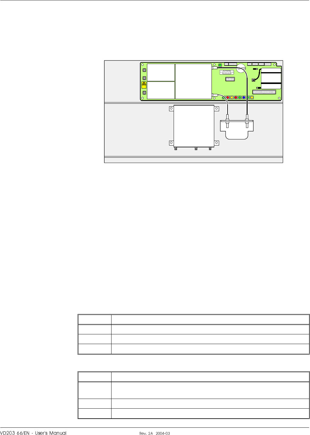
FOU – Fiber Optic Unit
FOU is an add on unit for the various repeater types. In the simplest
form, the FOU is a metal plate on which a FON board, a duplex filter
(DPX) and fiber optic connectors are assembled. This form of the FOU is
shown in Figure 5-19.
The FOU can, however, be configured with a FOT board instead of the
FON board, combiners, OSPs and WDMs to obtain a desired combination
of several branches with double or single fiber communication.
The add on FOU is used in the BMUs, RMUs and FORs and it is
mounted on top of the cover plate in the upper part of the repeaters.
The FON board is described on page 5-46, the FOT board on page 5-50.
Connection
The connection is depending on the repeater type and if the FOU is
connected at the BS or MS side of the repeater. The RF connection for
the FOU is shown in the following tables. The FON control ports are
described in the next section (page 5-46).
DPX connection with the FOU on the BS side (e.g. FOR).
Port Connected to
ANT ANT on the DPX/BS duplex filter.
HI P102 on the FON board. P301 on the FOT board.
LOI P101 on the FON board. P101 on the FOT board.
DPX connection with the FOU on the MS side (e.g. BMU and RMU).
Port Connected to
ANT BMU: BS –20dB on the DC/BS Directional Coupler.
All other types: ANT on the DPX/MS duplex filter
HI P101 on the FON board. P101 on the FOT board.
LO P102 on the FON board. P301 on the FOT board.
P102
P130
Beryllium
oxide
hazard
P103
P101
P114
P108P112P111
P105
P110
P109P115
P106
P104
RX
TX
P113
FON / FOT
DPX
ANTLO HI
P102
P101
FOU
Figure 5-19. FOU, Fiber Optic Unit
LGP Allgon AB H|H#H ¦o6cro#fH6c|cro
SaVS
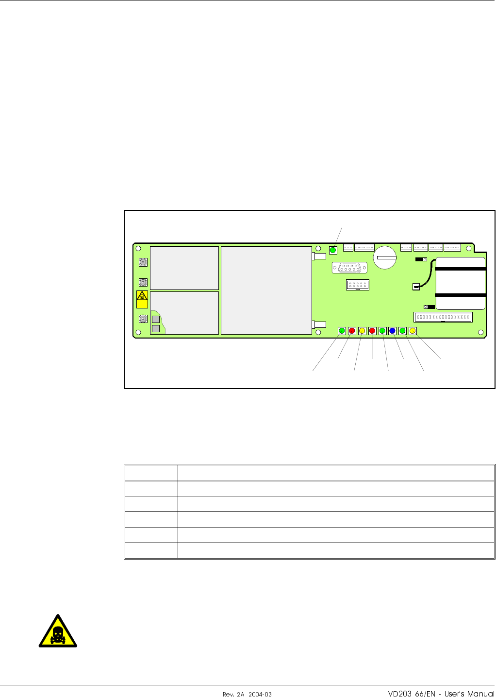
FON – Fiber Optic Node Board
The FON board converts RF signals to optic signals and the other way
round. Also, it contains very much of the repeater control features, such
as:
–Supervision of the RF and optical signaling.
–Internal and external alarm handling.
–RS232 interface port for local PC control.
–Interface port for RCC.
–Functionality and interface port for R2R Repeater to Repeater Link.
–Functionality and interface port for F2F Fiber to Fiber Link.
–Battery backup with charger.
The FON board is built up on a printed circuit board that also contains
the battery backup. The FON board is shown in Figure 5-20.
RF and optical ports
Port Description
P101 RF input signal (converts to optical TX).
P102 RF output signal (converted from optical RX).
P103 RF low power output signal (15dBm below the P102 signal).
RX Optical reception (to RF output port P102 and P103).
TX Optical transmission (from RF input port P101).
P101 and P102 are connected to the DPX as described on page 5-45.
Caution
H«ffc¦jrªc?H
There are two attenuators at the P101 port on the FON board that may
contain beryllium oxide (BeO), which is poisonous. The attenuators are
found inside the shield. See Chapter 1, Safety.
OPER
FAULT
POWER
BOOT
P102
P130
Beryllium
oxide
hazard
P103
P101
P114
P108P112P111
P105
P110
P109P115
P106
P104
RX
TX
P113
R2R
DATA
BATT
CHARGE
F2F
Figure 5-20. FON, Fiber Optic Node board
¦o6cro#fH6c|cro H|H#H LGP Allgon AB
SaV
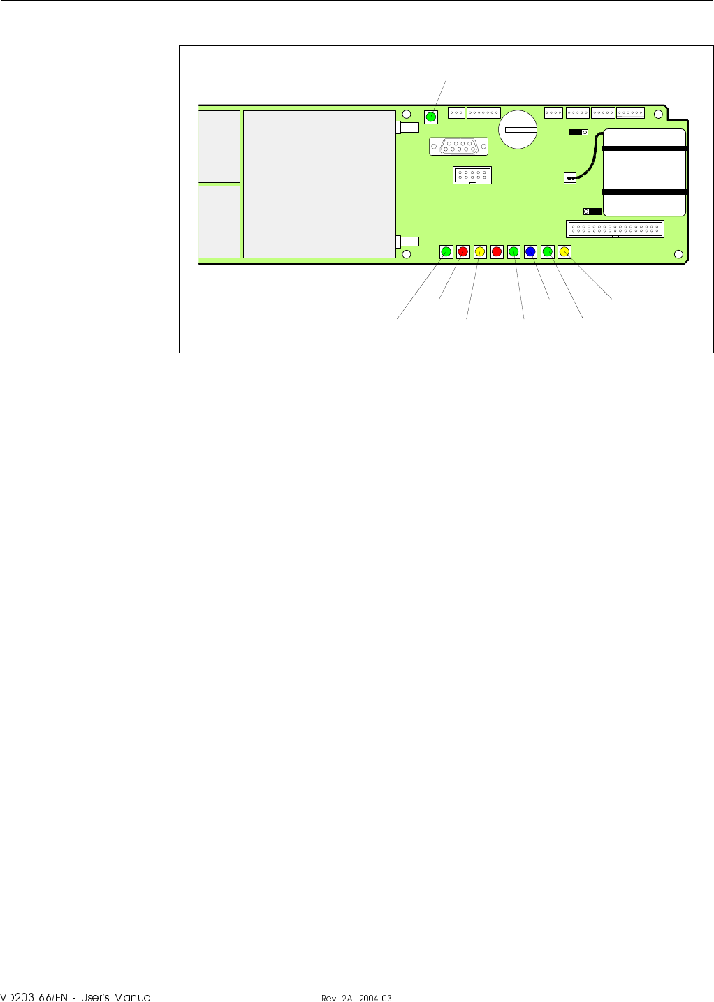
Indicators
The FON board contains the following LED indicators:
F2F
Green LED that indicates, with a flashing light, that the repeater
currently is a F2F Control Station. A steady light indicates that the
repeater is not currently a Control Station, or there is no more repeater
in the net. Only one repeater in an F2F net can show a flashing green
LED at the same time.
OPER
Green LED that lights up approx. 15 seconds after the mains is switched
on. It shows, with a steady light, that the unit is ready for operation.
FAULT
Red LED that flashes 15 – 20 seconds after the mains is switched on.
Then, it flashes for less serious alarms (ERROR) and is lit with a steady
light for fatal alarms (CRITICAL).
POWER
Yellow LED that is lit with a steady light after the mains is switched on.
Indicates present power.
BOOT
Red LED that is lit with a steady light when the system boots, i.e. for
10 – 15 seconds after the mains is switched on. Then, it flashes for the
next 5 – 10 seconds. After that, if no error is detected, the LED is off.
R2R
Green LED that indicates, with a flashing light, that the repeater
currently is a R2R Control Station. A steady light indicates that the
repeater is not currently a Control Station, or there is no more repeater
in the net. Only one repeater in an R2R net can show a flashing green
LED at the same time.
OPER
FAULT
POWER
BOOT
P130
P114
P108P112P111
P105
P110
P109P115
P106
P104
RX
TX
P113
R2R
DATA
BATT
CHARGE
F2F
Figure 5-21. FON indicators and ports
LGP Allgon AB H|H#H ¦o6cro#fH6c|cro
SaV
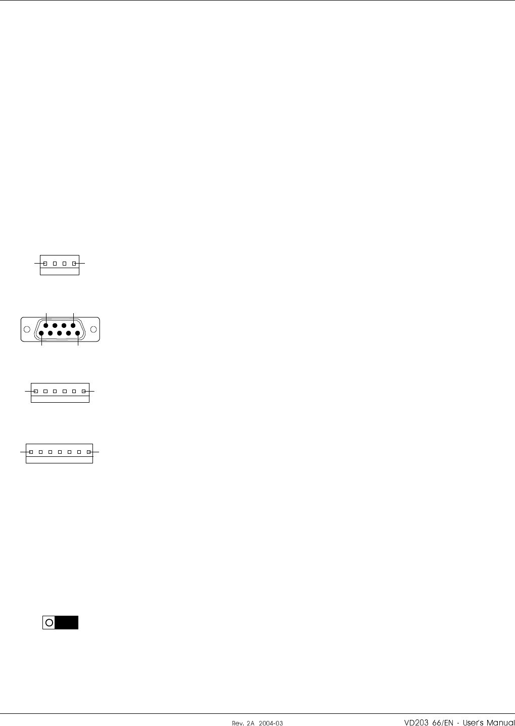
DATA
Blue LED that indicates data transmission in the R2R or F2F net.
BATT
Green LED that indicates, with a steady light, that the batteries currently
are used as power source.
CHARGE
Yellow LED that indicates battery charge with a steady light.
Connection ports
Except for the RF and optic ports, the FON board contains the following
connection ports:
P104 – Debug
This port is only used for development and debugging.
P105 – Front LED indicators
P105 is a 4 pole male connector used for the yellow and red LED
indicators on the front.
P106 – PC port
P106 is a 9 pole D-sub female RS-232 port used for local PC
communication. This port is identical to the P31 PC port, see the
description on page 5-53.
P108 – Power
P108 is a 6 pole male connector used for providing the FON board with
power. This connector is not used in Compact repeaters (information for
Compact repeater manual reference).
P109 – Alarm
P109 is a 7 pole male alarm connector used for external alarm sensors
and alarm equipment.
This port is the same port as the P33 alarm port described on page 5-54,
but P109 has the following pinning:
Pin 1 AIC Ground
Pin 2 AIC Ground
Pin 3 AI1 External alarm input 1 – EAL1.
Pin 4 AI2 External alarm input 2 – EAL2.
Pin 5 AI3 External alarm input 3 – EAL3.
Pin 6 AI4 External alarm input 4 – EAL4.
Pin 7 Not used
P110
This jumper is used to terminate an R2R link. It has to be set in the
parking state for all repeaters, except for the last repeaters in an R2R net.
Parking state is shown in the figure (the pins closest to the battery pack
interconnected).
The opposite state terminates the R2R net.
14
51
6 9
16
17
¦o6cro#fH6c|cro H|H#H LGP Allgon AB
SaVI
P111, P112 – R2R ports
P111 and P112 are 5 pole male connectors used for the Repeater to
Repeater Link feature (R2R net).
P111 and P112 are identical and connected in series. One of the
connectors are intended to be used from the previous repeater in the net
chain, and the other connector to the next repeater in the net chain.
Either of P111 or P112 can be used for the first and the last repeater in
the net chain.
Use straight connection between P111 and P112 connectors.
No termination is required for the outermost repeaters in an R2R net.
P113 – Batteries
P113 is a 2 pole male connector used for the backup batteries.
P114 – Repeater type
This jumper has to be OFF for all the AR repeater types, i.e. all the
repeaters mentioned in this manual. ON state is used for Compact
repeaters only. The OFF state is shown in the figure (the pins closest to
the battery pack interconnected).
P115 – Future port
P115 is a 3 pole male connector intended for future use (not used for the
time being).
P130 – RCU port
P130 is a 34 pole 2 line male connector used for connecting an RCC,
Remote Communication Control unit.
The P130 connector contains modem connection, RCC power supply, etc.
15
12
13
234
1 33
LGP Allgon AB H|H#H ¦o6cro#fH6c|cro
SaVp
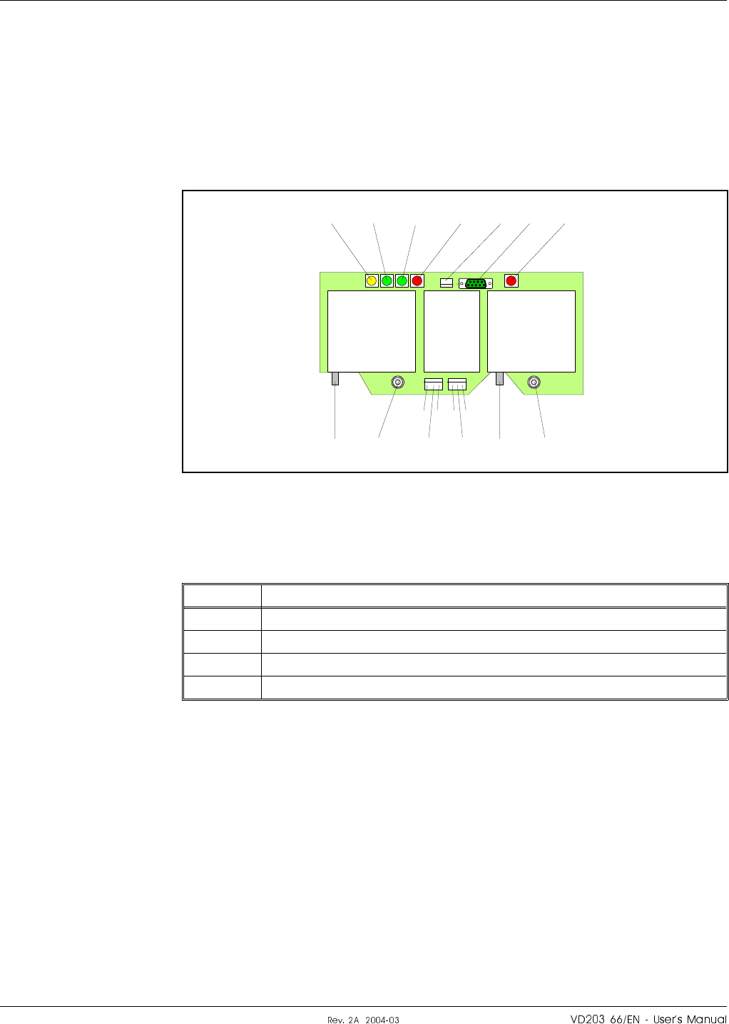
FOT – Fiber Optic Transceiver Board
The FOT board converts RF signals to optic signals and the other way
round. It also contains a simple supervision functionality consisting of a
signal monitoring and error signaling if the fiber optic signal is no longer
active.
The FOT board is built up on a printed circuit board. The FOT board is
shown in Figure 5-22.
RF and optical ports
Port Description
P101 RF input signal (converts to optical TX). SMA connector.
P301 RF output signal (converted from optical RX). SMA connector.
RX Optical reception (to RF output port P301).
TX Optical transmission (from RF input port P101).
P101 to P301 are connected to the DPX as described on page 5-45.
TX RX
P503
P502
7711
P301P101
PWR RXOK OPER ALARM P501 P401 BOO
T
TX RX
Figure 5-22. FOT indicators and ports
¦o6cro#fH6c|cro H|H#H LGP Allgon AB
SaS®
Indicators
The FON board contains the following LED indicators:
PWR
Yellow LED that is lit with a steady light after the mains is switched on.
Indicates present power.
RXOK
Green LED that indicates that the unit is ready to receive optic signals.
OPER
Green LED that lights up approx. 15 seconds after the mains is switched
on. It shows, with a steady light, that the unit is ready for operation.
ALARM
Red LED that flashes 15 – 20 seconds after the mains is switched on.
Then, it flashes for less serious alarms (ERROR) and is lit with a steady
light for fatal alarms (CRITICAL).
BOOT
Red LED that is lit with a steady light when the system boots, i.e. for
10 – 15 seconds after the mains is switched on. Then, it flashes for the
next 5 – 10 seconds. After that, if no error is detected, the LED is off.
Connection ports
Except for the RF and optic ports, the FOT board contains the following
connection ports:
P401 – PC port
P401 is a 9 pole D-sub female RS-232 port used for local PC
communication. This port is identical to the P31 PC port, see the
description on page 5-53.
P501 – Master unit
Connector for master unit.
P502 and P503 – Power
Power and alarm port for the FOT board.
P502 and P503 have the following pinning:
Pin 1 +7V
Pin 2 +7V
Pin 3 Alarm
Pin 4 GND
Pin 5 Shut down.
Pin 6 GND
51
6 9
LGP Allgon AB H|H#H ¦o6cro#fH6c|cro
SaSu
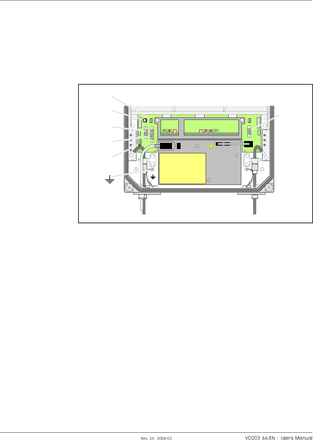
Connection Ports
The DIA distribution board provides most of the internal connection
between the repeater units, and to external ports. Connectors involved in
the installation are also located on the DIA board. These connectors are
described below. A complete DIA board connector list is found on
page 5-37.
Figure 5-23 shows the location of the connection ports.
Station ground is also shown in Figure 5-23 (at the ground symbol).
The port descriptions are found on the following pages:
P27 Auxiliary Port ............................................................................. page 5-53
P28 Door switch alarm input port ........................................................... 5-55
P31 PC Port ............................................................................................... 5-53
P32 Modem Port ........................................................................................ 5-54
P33 Alarm Port .......................................................................................... 5-54
P34 Repeater to Repeater Link Port ....................................................... 5-56
MRX
DPX
ANT
TEST
DC
-30 dB
BS
-20 dB
MRX
DPX
ANT
TEST
DC
-30 dB
P33
P27
P31
P32
P28
P34
Figure 5-23. Connection ports and station ground
¦o6cro#fH6c|cro H|H#H LGP Allgon AB
SaS¤
P27 Auxiliary Port
Auxiliary port P27 is used to power the RCU, Remote Control Unit, for
communication with the repeater.
The connector is found on the DIA board to the left in the cabinet.
P27 is an 8 pole, 1 line male connector.
Pin 2 and 3 of the P27 port must always be interconnected to provide the
CU and ALI boards with voltage supply. If there is no cable connected to
the P27 port, pin 2 and 3 must be interconnected with a jumper.
P27 auxiliary connector pinning
Pin 1 +7V DC.
Pin 2 +7V DC.
Pin 3 CU and ALI power supply from pin 2.
Pin 4 GND
Pin 5 +26V DC or +13V DC depending on the repeater type.
Pin 6 Not used.
Pin 7 Output 200KHz reference.
Pin 8 GND
P31 PC Port
PC port P31 is a RS-232 port used for local PC communication.
The connector is found on the DIA board to the right in the cabinet.
P31 is a 9 pole D-sub female connector.
P31 PC connector pinning
Pin 1 Not used.
Pin 2 Data from repeater to OMT32.
Pin 3 Data from OMT32 to repeater.
Pin 4 DTR from OMT32 to repeater.
Pin 5 GND
Pin 6 DSR from repeater to OMT32.
Pin 7 RTS from OMT32 to repeater.
Pin 8 CTS from repeater to OMT32.
Pin 9 Not used.
18
51
6 9
LGP Allgon AB H|H#H ¦o6cro#fH6c|cro
SaS
P32 Modem Port
Modem port P32 is a RS-232 port with V.24 interface used for the RCU,
Remote Control Unit.
The connector is found on the DIA board to the left in the cabinet.
P32 is a 9 pole D-sub male connector.
P32 modem connector pinning
Pin 1 DCD
Pin 2 RXD
Pin 3 TXD
Pin 4 DTR
Pin 5 GND
Pin 6 DSR
Pin 7 RTS
Pin 8 RFS
Pin 9 RI
P33 Alarm Port
Alarm port P33 is used for external alarm sensors and alarm equipment.
The connector is found on the DIA board to the left in the cabinet.
P33 is a 15 pole D-sub female connector.
The port has four alarm inputs, EAL1 - EAL4, and two alarm outputs.
Four alarm inputs
The inputs are low-level inputs with common ground (AIC).
Use insulated switch or relay to initiate alarms (open switches in normal
operating mode, closed switches cause alarm).
The alarm switch connection can be toggled between being active open or
active closed. This is further described in the OMT32, User’s Manual and
in the Advanced Repeater OMS, User’s Manual.
The alarm input voltage ratings, related to ground (AIC), are:
Vinmax = 5.5V
Vinmin =–0.5V
P33 alarm connector pinning
Pin 14 AI1 External alarm input 1 - EAL1.
Pin 15 AI2 External alarm input 2 - EAL2.
Pin 7 AI3 External alarm input 3 - EAL3.
Pin 8 AI4 External alarm input 4 - EAL4.
Pin 6 AIC Ground.
5 1
69
81
159
¦o6cro#fH6c|cro H|H#H LGP Allgon AB
SaSV
P28 - AI4 door switch alarm input
Normally, alarm input AI4 is used for repeater cover opening alarm
EAL4, which is arranged using a door switch (optional). Because of that,
AI4 and AIC are available also in the P28 connector, to which the door
switch is connected.
The connector is found on the DIA board to the left in the cabinet.
The EAL4 door switch alarm is activated 10 – 30 seconds after the cover
has been opened.
Two alarm outputs
Both the alarm outputs are 1 pole closing and 1 pole opening relay
outputs insulated from each other.
Maximum ratings, related to ground or any other alarm terminal, are
50VAC/60VDC.
The alarm outputs are defined as follows:
Pin 9-1 AO1 – AO8 Closed when operating, otherwise open.
Pin 10-2 AO6 – AO7 Open when operating, otherwise closed.
Pin 11-3 AO2 – AO5 Closed at alarm state, otherwise open.
Pin 12-4 AO3 – AO4 Open at alarm state, otherwise closed.
P33 alarm connector pinning
Pin 1 AO8
Pin 2 AO7
Pin 3 AO5
Pin 4 AO4
Pin 5 Not used.
Pin 6 AIC
Pin 7 AI3
Pin 8 AI4
Pin 9 AO1
Pin 10 AO6
Pin 11 AO2
Pin 12 AO3
Pin 13 Not used.
Pin 14 AI1
Pin 15 AI2
13
81
159
LGP Allgon AB H|H#H ¦o6cro#fH6c|cro
SaSS

P34 Repeater to Repeater Link Port
The P34 port is used for the R2R, Repeater to Repeater Link, which is an
optional feature for the AR repeaters. This port is also used to
interconnect the F2F, Fiber to Fiber Link feature, to the R2R net.
The connector is found on the DIA board to the left in the cabinet.
P34 is an 8 pole RJ45 modular female connector.
By interconnecting the P111 or P112 on the FON board to this port, the
F2F net is included in the R2R net and all repeaters in both the nets are
accessible.
P34 Repeater to Repeater Link connector pinning
Pin 1 C/S
Pin 2 GND
Pin 3 D–
Pin 4 D+
Pin 5 D+
Pin 6 D–
Pin 7 GND
Pin 8 C/S
For further information about the Repeater to Repeater Link installation,
refer to the VD202 91/EN R2R, Repeater to Repeater Link Kit, Installation
Guide.
¦o6cro#fH6c|cro H|H#H LGP Allgon AB
SaS

Cabling
On the following pages, you will find cabling information for the various
repeater types:
•Channel selective GSM repeater, two channels, page 5-58.
•Channel selective GSM repeater, four channels, page 5-59.
•Channel selective CDMA with MRX, two channels, page 5-60.
•Channel selective WCDMA, two channels, page 5-61.
•Channel selective high power CDMA/WCDMA, two channels, page 5-62.
•Band selective repeater, page 5-63.
•BMU, page 5-64.
•RMU, page 5-65.
•FOR, page 5-66.
LGP Allgon AB H|H#H ¦o6cro#fH6c|cro
SaS
Channel Selective GSM Repeater, Two Channels
Figure 5-24 shows a repeater equipped with the CHA1/DL and CHA3/UL
channel boards for two bi-directional GSM channels.
MS
DPX
ANT
TEST
DC
-30 dB
-20 dB BS
DPX
ANT
TEST
DC
-30 dB
-20 dB
OUT
LOWIN+7V ATTOUT2 OUT1
LNA
DL
OUT
LOW IN ATT +7V OUT1 OUT2
LNA
UL
PSU
DPX
MS
HI
ANT
LO
DPX
BS
HI
ANT
LO
CHA1/DL
P101
P701
CHA3/UL
P101
P701
MS BS
1 2
1 2
DC
BS
DC
MS
LNA
DL
LNA
UL
Figure 5-24. Cabling, 2 channel GSM repeater
¦o6cro#fH6c|cro H|H#H LGP Allgon AB
SaSI
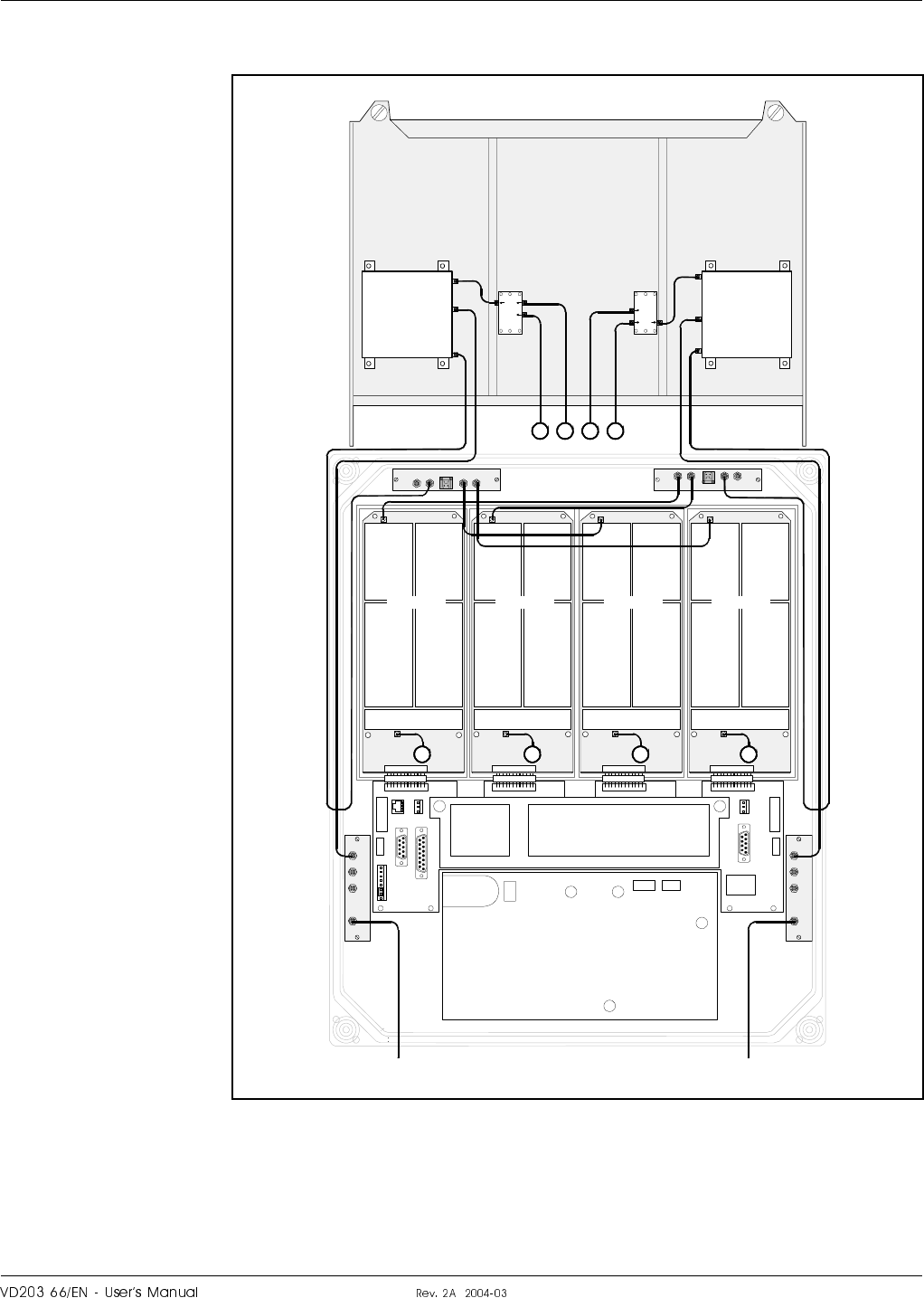
Channel Selective GSM Repeater, Four Channels
Figure 5-25 shows a channel selective repeater equipped with the
CHA1/DL, CHA2/DL, CHA3/UL, and CHA4/UL channel boards for four
bi-directional GSM channels.
MS
DPX
ANT
TEST
DC
-30 dB
-20 dB BS
DPX
ANT
TEST
DC
-30 dB
-20 dB
OUT
LOWIN+7V ATTOUT2 OUT1
LNA
DL
OUT
LOW IN ATT +7V OUT1 OUT2
LNA
UL
PSU
DPX
MS
HI
ANT
LO
DPX
BS
HI
ANT
LO
CMB
UL
CMB
DL
CHA1/DL
P101
P701
CHA2/DL
P101
P701
CHA3/UL
P101
P701
CHA4/UL
P101
P701
DC
BS
DC
MS
MS BS
1 2 3 4
1 2 3 4
LNA
DL
LNA
UL
Figure 5-25. Cabling, 4 channel GSM repeater
LGP Allgon AB H|H#H ¦o6cro#fH6c|cro
SaSp
Channel Selective CDMA Repeater With MRX, Two Channels
Figure 5-26 shows a channel selective high power CDMA repeater
equipped with two CSA boards, two PA boards, a BA board (in the cover)
and an MRX unit.
MRX
DPX
ANT
TEST
DC
-30 dB
MS
-20 dB
MRX
DPX
ANT
TEST
DC
-30 dB
BS
-20 dB
OUT
LOWIN+7V ATTOUT2 OUT1
LNA
DL
OUT
LOW IN ATT +7V OUT1 OUT2
LNA
UL
PSU
CSA/DL
P101
P301
P4
P5
PA/DL CSA/UL
P101
P301
MS BS
1
1
P5
PA/UL
P4
2
DPX
MS
LO
ANT HI
DPX
BS
LO
ANT HI
2
P102 P101
MRX
DC
BS
DC
MS
LNA
DL
LNA
UL
Figure 5-26. Cabling, 2 channel CDMA repeater with MRX
¦o6cro#fH6c|cro H|H#H LGP Allgon AB
Sa®
Channel Selective WCDMA Repeater, Two Channels
Figure 5-27 shows a channel selective WCDMA repeater equipped with
two CSA boards and two PA boards.
MS
DPX
ANT
TEST
DC
-30 dB
-20 dB BS
DPX
ANT
TEST
DC
-30 dB
-20 dB
OUT
LOW
IN+7V ATTOUT2 OUT1
LNA
DL
OUT
LOW IN ATT +7V OUT1 OUT2
LNA
UL
PSU
CSA/DL
P101
P301
P4
P5
PA/DL CSA/UL
P101
P301
MS BS
1
1
P5
PA/UL
P4
2
DPX
MS
LOANT HI
DPX
BS
LOANT HI
2
DC
BS
DC
MS
LNA
DL
LNA
UL
Figure 5-27. Cabling, 2 channel WCDMA repeater
LGP Allgon AB H|H#H ¦o6cro#fH6c|cro
Sau
Channel Selective High Power CDMA/WCDMA Repeater, Two Channels
Figure 5-28 shows a channel selective high power CDMA repeater
equipped with two CSA boards, two PA boards and a BA board (in the
cover). The high power CDMA repeater is available for two channels only.
MRX
DPX
ANT
TEST
DC
-30 dB
BS
-20 dB
MRX
DPX
ANT
TEST
DC
-30 dB
OUT
LOWIN+7V ATTOUT2 OUT1
LNA
DL
OUT
LOW IN ATT +7V OUT1 OUT2
LNA
UL
PSU
CSA/DL
P101
P301
P4
P5
PA/DL CSA/UL
P101
P301
BS MS
1
P5
PA/UL
P4
2
DPX
BS
LO
ANT HI
2
P102 P101
MRX
PSU2
BA/DL
P3
P4
DPX
MS
LO
ANT HI
1
3
3
DC
MS
DC
BS
LNA
DL
LNA
UL
Figure 5-28. Cabling, 2 channel high power CDMA/WCDMA
¦o6cro#fH6c|cro H|H#H LGP Allgon AB
Sa¤
Band Selective Repeater
Figure 5-29 shows a band selective repeater equipped with two BSA
boards and two PA boards.
MS
DPX
ANT
TEST
DC
-30 dB
-20 dB BS
DPX
ANT
TEST
DC
-30 dB
-20 dB
OUT
LOW
IN+7V ATTOUT2 OUT1
LNA
DL
OUT
LOW IN ATT +7V OUT1 OUT2
LNA
UL
PSU
BSA/DL
P101
P301
P4
P5
PA/DL BSA/UL
P101
P301
MS BS
1
P5
PA/UL
P4
2
DPX
MS
HI
ANT
LO
DPX
BS
HI
ANT
LO
1 2
DC
BS
DC
MS
LNA
DL
LNA
UL
Figure 5-29. Cabling, band selective repeater
LGP Allgon AB H|H#H ¦o6cro#fH6c|cro
Sa
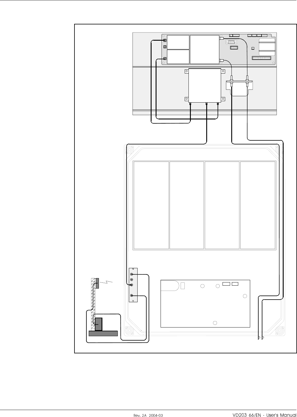
BMU
Figure 5-30 shows a BMU with a FON board. In this type, the BTS
antenna signal is passing through the Directional Coupler (DC-BS). The
service side has a fiber optic connection port for a FOR.
BS
DPX
ANT
TEST
DC
-30 dB
-20 dB
PSU
FOR
DPX
ANTLO HI
RX
TX
FON / FOT
P102
P101
BTS
DC
BS
FOU
TX RX
Figure 5-30. Cabling, BMU
¦o6cro#fH6c|cro H|H#H LGP Allgon AB
SaV
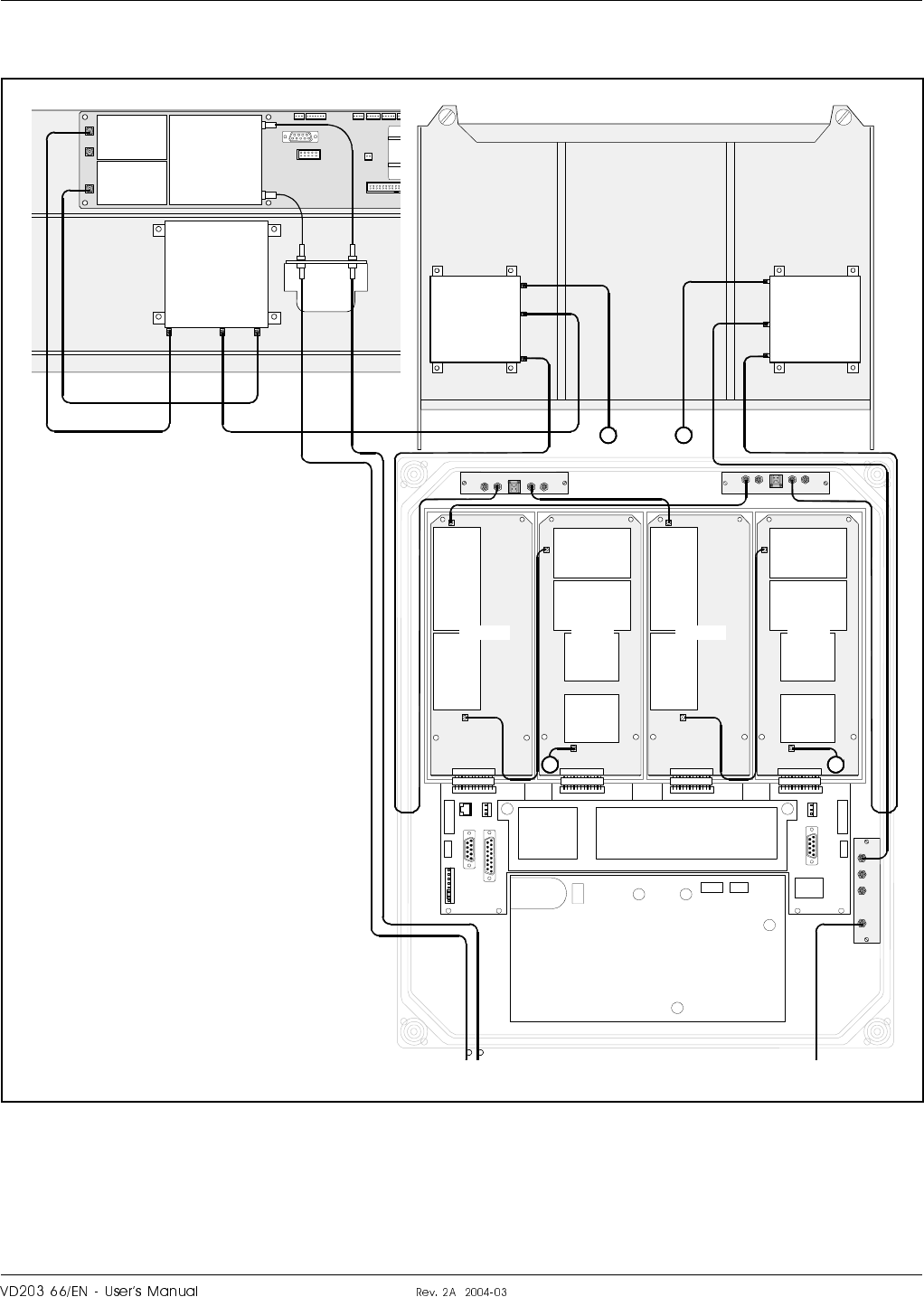
RMU
Figure 5-31 shows an RMU for band selective operation equipped with a
FON board, two BSA boards and two PA boards. The MS side has a fiber
optic connection port for a FOR.
RX
TX
FON / FOT
DPX
ANTLO HI
P102
P101
BS
DPX
ANT
TEST
DC
-30 dB
-20 dB
OUT
LOW
IN+7V ATTOUT2 OUT1
LNA
DL
OUT
LOW IN ATT +7V OUT1 OUT2
LNA
UL
PSU
BSA/DL
P101
P301
P4
P5
PA/DL BSA/UL
P101
P301
FOR BS
1
P5
PA/UL
P4
2
DPX
MS
HI
ANT
LO
DPX
BS
HI
ANT
LO
1 2
FOU
TX RX
DC
BS
LNA
DL
LNA
UL
Figure 5-31. Cabling, RMU
LGP Allgon AB H|H#H ¦o6cro#fH6c|cro
SaS
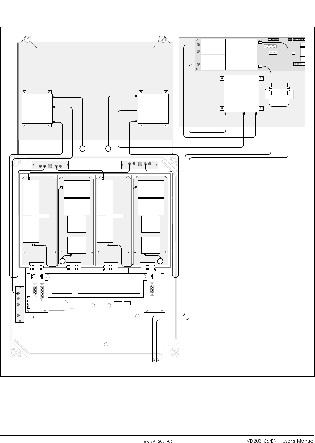
FOR
Figure 5-32 shows a FOR for band selective operation equipped with a
FON board, two BSA boards and two PA boards. The BS side has a fiber
optic connection port for a BMU, RMU or another FOR.
MS
DPX
ANT
TEST
DC
-30 dB
-20 dB
OUT
LOW
IN+7V ATTOUT2 OUT1
LNA
DL
OUT
LOW IN ATT +7V OUT1 OUT2
LNA
UL
PSU
BSA/DL
P101
P301
P4
P5
PA/DL BSA/UL
P101
P301
MS BMU/RMU/FOR
1
P5
PA/UL
P4
2
DPX
MS
HI
ANT
LO
DPX
BS
HI
ANT
LO
1 2
RX
TX
FON / FOT
DPX
ANTLO HI
P102
P101
FOU
TX RX
DC
MS
LNA
DL
LNA
UL
Figure 5-32. Cabling, FOR
¦o6cro#fH6c|cro H|H#H LGP Allgon AB
Sa
Repeater Software and Hardware Compatibility
There are different versions of repeater CU software, which can be
combined with boards of various revisions. These have unique part
numbers and revision information. Below, you will find a table of repeater
software currently available in combination with CU board revisions.
CU Board
Part #
CU Software Comments
Part # Latest
revision
K103/1
or
K103/2
SA102 01/2 R2E For GSM channel selective
≤4 channels, band selective
800-900MHz fixed
bandwidth only, and combi
(800/900MHz).
No traffic statistics.
K103/2 SA102 02/1 R3A For GSM, EGSM, DCS,
PCS channel selective
≤8 channels, band selective
800-900MHz fixed or
adjustable bandwidth, band
selective 1800MHz or
1900MHz and combi.
Supports R2R link.
R3C Supports stacked channels.
K103/2 SA102 02/2 R1A For 800/1900MHz CDMA
≤4 channels. Supports MRX
R2A Supports R2R.
This information is updated 2001-06-28.
As new versions of hardware and software are released without prior
noticing, contact your LGP Allgon sales representative if in doubt about
the latest revision status.
For detailed information, refer to the release notes for the CU software to
be downloaded (normally found in the readme.txt file provided with the
program files).
LGP Allgon AB H|H#H ¦o6cro#fH6c|cro
Sa

¦o6cro#fH6c|cro H|H#H LGP Allgon AB
SaI

6. Optionals
This chapter describes the following optional accessories available for the
LGP Allgon repeaters:
•RCU, Remote Control Unit for GSM 900/1800/1900, page 6-2.
•RCU, Remote Control Unit with PCMCIA Modem, page 6-4.
•RCC, Remote Communication Control unit, page 6-6.
•R2R, Repeater To Repeater Link, page 6-7.
•Traffic Statistics, page 6-9.
•Battery Backup, page 6-9.
•7/16" Antenna Cable Connectors, page 6-9.
•OMS, Operation and Maintenance System, page 6-9.
LGP Allgon AB H|H#H |cro#f
au
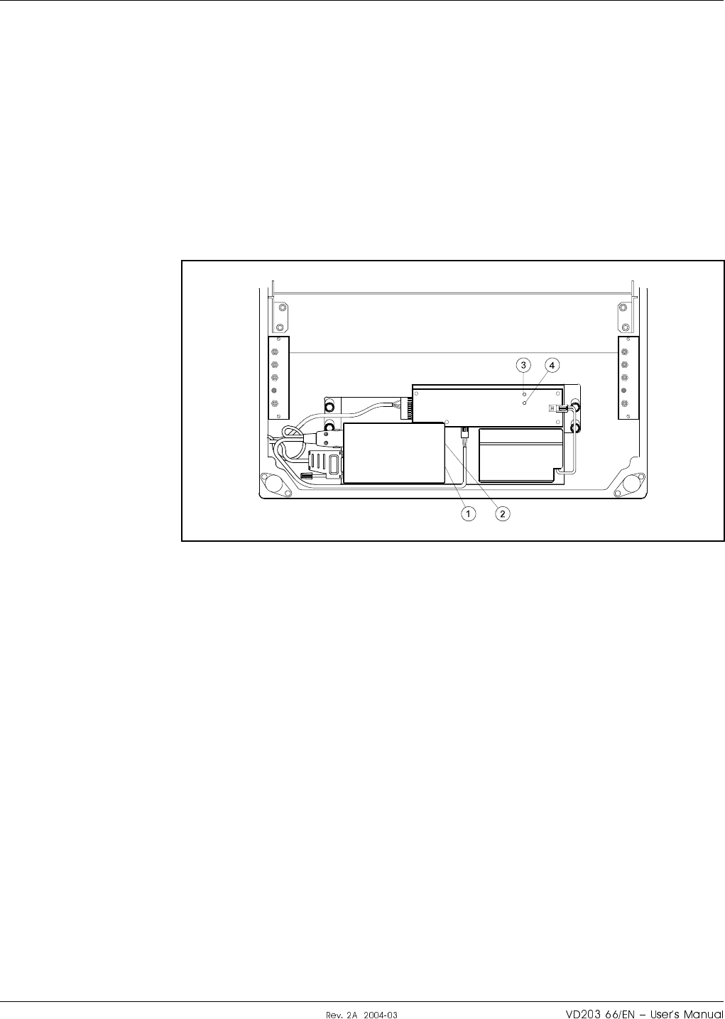
RCU, Remote Control Unit for GSM 900/1800/1900
As the mobile phone technology is developing very fast, this RCU may be
modified after issuing this manual. New types may also have been added.
For the latest details, please contact your local LGP Allgon representative.
For remote control of LGP Allgon repeaters in the GSM 900 system an
RCU Remote Control Unit is available as a kit. This kit contains an
integrated mobile phone/modem, power supply and power supply backup.
A detailed installation guide is also included in the RCU kit.
The RCU for the GSM system is mounted inside the repeater cabinet, in
front of the PSU (see Figure 6-1).
The RCU is connected to the P27, P32, and MS –20dB ports.
12volt 0.7Ah
MS
DPX
ANT
TEST
DC
-30 dB
-20 dB
MS
DPX
ANT
TEST
DC
-30 dB
-20 dB
Figure 6-1. RCU - GSM 900 type
|cro#f H|H#H LGP Allgon AB
a¤

RCU kit items
The item numbers refer to the numbers in Figure 6-1.
1. The GSM board. Press a pencil or similar object on the small button
adjacent to the SIM board to release it.
2. LED indicator on the M1 phone/modem unit which shows three
operational modes:
Out: The unit is off
Slow flashing: Stand by
Fast flashing: Connection in progress
3. Green LED on the battery charger which is lit with a steady light
when the power supply is OK, either from the mains or from the
battery.
4. Yellow LED on the battery charger which is lit with a steady light
during battery charge from the mains.
Do not forget to put a jumper between pin 2 and 3 on the P27 connector if
you disconnect the RCU.
GSM subscriber conditions
•Data transmission, 9600 bps (baud)
•Transparent mode
•If the PIN code have to be disabled, use another phone.
If you get problems with the PIN code, please contact LGP Allgon
Technical Support.
Power supply backup
If a power failure occurs, the backup battery has capacity to supply the
CU, ALI and phone/modem for 30 minutes at room temperature and a
limited number of call attempts.
The battery life is 1 – 2 years at normal indoor temperature. If the
operational temperature is higher, the battery life is shortened.
Power supply battery type
12V, 0.7A/20h, lead, sealed, including cable and JST VHR-2N connector.
Part # LGP Allgon: PM291 09/1
Hitachi: HP0.7-12P (VHR-2N)
Yuasa: NP0.8-12
LGP Allgon AB H|H#H |cro#f
a

RCU, Remote Control Unit with PCMCIA Modem
As the mobile phone technology is developing very fast, this RCU may be
modified after issuing this manual. New types may also have been added.
For the latest details, please contact your local LGP Allgon representative.
For remote control of LGP Allgon repeaters in various systems the
following PCMCIA modem based RCU Remote Control Units is available
as a kit:
•RCU Kit for PCMCIA – Fixed Wire Line Connection.
This RCU does not include accessories for a mobile phone.
Detailed installation guide is included in the RCU kit.
RCU Kit for PCMCIA – Fixed Wire Line Connection
This kit contains a PCMCIA card host, power supply, and power supply
backup.
Most Hayes compatible PCMCIA card modems (not included in the kit)
can be used.
Power supply backup
If a power failure occurs, the included backup battery has capacity to
supply the CU, ALI and the modem. For the Wireless Connection type,
this is applicable provided the specified configuration of mobile phone and
PCMCIA modem is used.
The battery life is 1 – 2 years at normal indoor temperature. If the
operational temperature is higher, the battery life is shortened.
|cro#f H|H#H LGP Allgon AB
aV
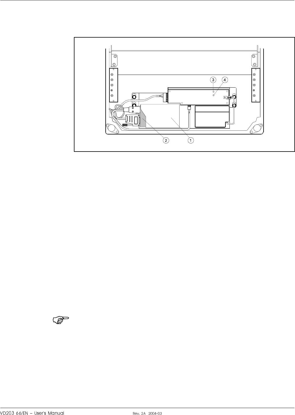
RCU for Fixed Wire Line Connection
The RCU for Fixed Wire Line Connection is mounted inside the repeater
cabinet, in front of the PSU (see Figure 6-2).
The RCU is connected to the P27 and P32 ports.
A free strain relief bushing at the bottom of the repeater is used for the
external telephone line cable.
RCU kit items
The item numbers refer to the numbers in Figure 6-2.
1. PCMCIA modem card host.
2. PCMCIA modem card (not included in the kit).
3. Green LED on the battery charger which is lit with a steady light
when the power supply is OK, either from the mains or from the
battery.
4. Yellow LED on the battery charger which is lit with a steady light
during battery charge from the mains.
Do not forget to put a jumper between pin 2 and 3 on the P27 connector if
you disconnect the RCU.
12volt 0.7Ah
MS
DPX
ANT
TEST
DC
-30 dB
-20 dB
MS
DPX
ANT
TEST
DC
-30 dB
-20 dB
Figure 6-2. RCU - Fixed Wire Line PCMCIA type
LGP Allgon AB H|H#H |cro#f
aS

RCC, Remote Communication Control Unit
The optional RCC Remote Communication Control unit is an alternative
to the RCU, provided the repeater has a FON board. The RCC unit is also
used in the Compact repeaters.
An RCC unit is required if the communication unit has to be connected to
a FON board, e.g. in the BMU (the FON board does not support the RCU).
Communication with the repeater is performed by means of a PSTN or
RF modem that has the antenna connected to the BS directional coupler
(DC) or has a separate antenna. Data is transferred between the repeater
and the RCC unit via the P130 modem port on the FON board.
The RCC unit is also powered via the same port and the unit has a
battery with capacity enough for sending a number of alarms if a mains
power failure occurs.
A description of the RCC and its connection is found in the VD203 67/EN,
ALR Compact Repeater, User’s Manual.
|cro#f H|H#H LGP Allgon AB
a
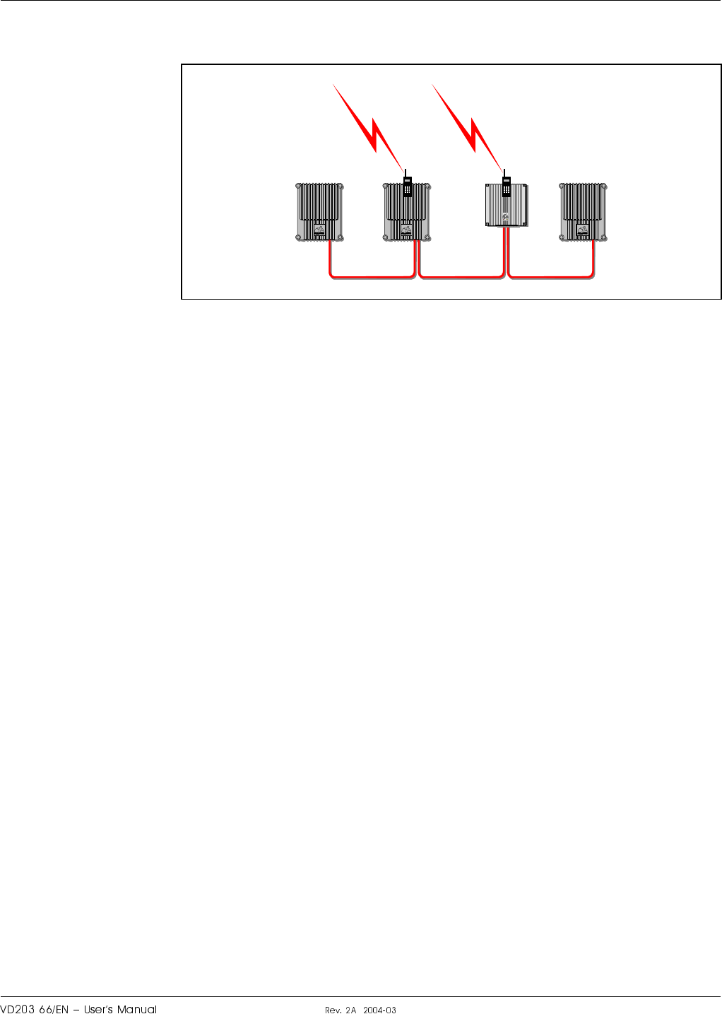
R2R, Repeater To Repeater Link
The LGP Allgon Repeater to Repeater Link can be used in order to
establish a repeater network with up to 13 repeaters, one or several of
which can contain a phone line for communication with an OMT32 or an
OMS.
All LGP Allgon repeaters can be included in a R2R net (see Figure 6-3).
Channel selective repeaters, band selective repeaters, and Compact
repeaters can be mixed in the same net. For Compact repeaters, the R2R
Repeater to Repeater Link feature is standard and requires no extra
hardware or software.
AR Repeaters can either be equipped with this feature at the delivery
from LGP Allgon, or be completed with a Repeater to Repeater Link Kit,
provided the repeaters meet the below requirements.
R2R Requirements
To be able to use the Repeater to Repeater Link feature, the following DIA
board, CU board and CU software are required:
DIA board K105/1 version R2A or higher.
CU board K103/2 version R1A or higher.
CU software SA102 02/1 version R3A or higher.
The version of the RIA board can be detected remotely by means of the
OMT32, see the OMT32, User’s Manual.
Further information and requirements are found in the R2R installation
document, R2R, Repeater to Repeater Link Kit, Installation Guide
(part # VD202 91/EN).
Figure 6-3. Repeater to Repeater Link
LGP Allgon AB H|H#H |cro#f
a

Installation
The R2R, Repeater to Repeater Link, is installed as described in the R2R,
Repeater to Repeater Link Kit, Installation Guide.
At least one RCU unit (or telephone line with modem) is required for
remote communication.
Configuration
Configuration is described in the OMT32, User’s Manual.
F2F Access
Communication with repeaters in a mixed F2F and R2R net is possible.
By interconnecting a F2F net with an R2R net, all repeaters in both the
nets are accessible. FON boards are, however, required for the repeaters
included in the F2F net (the FOT board does not support the F2F
feature).
|cro#f H|H#H LGP Allgon AB
aI

Traffic Statistics
Traffic statistics is available for channel selective GSM 900, GSM 1900
and DCS/PCN 1800 repeaters, provided that the repeaters have the latest
CU software versions, the latest CU and CHA boards, and that an OMS is
used to poll and view the statistics.
Battery Backup
Battery backup can be arranged by completing the repeater with an LGP
Allgon UPS (Uninterruptible Power Supply). The LGP Allgon UPS has an
exterior similar to the repeater which means that it can preferably be
mounted adjacent to the repeater.
7/16" Antenna Cable Connectors
A 7/16" antenna cable kit is available for all the LGP Allgon repeaters.
This kit includes 7/16" antenna connectors for uplink and downlink
antennas mounted on two repeater cable inlet flanges, and cables and
connectors for connection to the DC directional couplers inside the
repeater.
OMS, Operation and Maintenance System
The OMS, Operation and Maintenance System is an LGP Allgon software
package for controlling a large repeater fleet by using computers with
Windows NT in networks with a common database.
The OMS is capable of operating a large number of repeaters. Multiple
modems can be used for several incoming and outgoing parallel activities,
such as polling, radio parameter configuration, software downloading, etc.
OMS is an improved OMC, Operation and Maintenance Center. The latter
is replaced by the OMS and is no longer subject to further development.
LGP Allgon AB H|H#H |cro#f
ap

|cro#f H|H#H LGP Allgon AB
au®

7. Repeater Alarms
This chapter contains a list of those alarms which are initiated in the
repeater.
Critical, Error and Warning alarms can be sent automatically from a
repeater to an OMT32 and OMS and then be stored. These alarms can
then be viewed.
The alarm handling is described in the following manuals:
•OMT32, User’s Manual
•Advanced Repeater OMS, User’s Manual
The table starting on the following page contains those alarms that can be
generated by an AR repeater.
LGP Allgon AB H|H#H H|H#Hf#j
au

Alarm Reference List
The following table contains the internal repeater alarms which can occur
and be shown in the OMT32 and OMS alarm window (additional alarms
may have been added to the system after issuing this manual).
Alarm Text Alarm Unit Alarm Level Description
Antenna isolation BSA #
Channel #
UL/DL
Warning Antenna isolation is below the gain set. The gain is reduced
10 – 13dB below oscillation point.
Suggested remedy: Decrease the gain or increase the
antenna isolation.
Error The gain is reduced as much as possible but the oscillation
continues. The amplifier is turned off.
Suggested remedy: Decrease the gain or increase the
antenna isolation.
Ceasing The cause of the alarm has ceased.
Antenna SWR Donor or
service antenna Error Antenna SWR above preset limit.
Suggested remedy: Check antenna, connector and cables.
Ceasing The cause of the alarm has ceased.
Alarm reset CU None Manual alarm reset. Alarm criteria is re-evaluated and
reported if still active.
BA HW error BA # Error BA-BA link does not work properly.
Suggested remedy: Check cables between BA units.
Ceasing The cause of the alarm has ceased.
Bad table found CU Error Incorrect information detected in a table.
Suggested remedy: Replace the unit for calibration.
Battery backup fault External Configurable Battery backup fault (provided the external alarm 2 is
configured to display this alarm).
Ceasing The cause of the alarm has ceased.
Battery fault RCC unit,
FON charger Error The backup battery on the RCC unit or the FON board does
not work properly.
Suggested remedy: Check cables or replace battery.
Ceasing The cause of the alarm has ceased.
CU battery fault CU Warning CU RAM battery fault.
Suggested remedy: Make sure the P3 jumper is connected on
the CU board.
Ceasing The cause of the alarm has ceased.
Door open alarm 1) External Configurable Door open more than 30 seconds.
Ceasing Door closed more than 30 seconds or the alarm is disabled.
EEPROM error CU Error EEPROM read or write error.
Err in AD-converter CU Warning Unreliable value from the analog-to-digital converter.
Ext REFO error CU Warning An external reference is lost (e.g. GPS reference).
Suggested remedy: Check reference source and cables.
External alarm 1 External Configurable External alarm input 1 active more than 1 second.
Ceasing External alarm input 1 no longer active.
External alarm 2 External Configurable External alarm input 2 active more than 1 second.
Ceasing External alarm input 2 no longer active.
External alarm 3 External Configurable External alarm input 3 active more than 1 second.
Ceasing External alarm input 3 no longer active.
H|H#Hf#j H|H#H LGP Allgon AB
a¤

Alarm Text Alarm Unit Alarm Level Description
External alarm 4 External Configurable External alarm input 4 active more than 1 second.
Ceasing External alarm input 4 no longer active.
Fiberoptical error FOT Configurable Fiber optic error (provided the external alarm 3 is
configured to display this alarm).
Ceasing The cause of the alarm has ceased.
FON Laser RX Fault FON Error The received optical level is below the allowed limit set to
generate Error alarm.
Suggested remedy: Check the fiber optic cord.
Warning The received optical level is below the allowed limit set to
generate Warning alarm.
Suggested remedy: Check the fiber optic cord.
Ceasing The cause of the alarm has ceased.
FON Laser TX Fault FON Error The laser transmitter control loop voltage is out of range.
Suggested remedy: Replace the FON board.
Ceasing The cause of the alarm has ceased.
FON Power Fault FON Error A FON board DC power supply voltage is out of range.
Suggested remedy: Replace the FON board.
Ceasing The cause of the alarm has ceased.
FON RxStable alarm FON Warning Laser receiver input signal below preset warning limit.
Suggested remedy: Check FON board cables and connectors.
Error Laser receiver input signal below preset error limit.
Suggested remedy: Check FON board cables and connectors.
Ceasing The cause of the alarm has ceased.
FON SPI Error FON Error The SPI bus connection to the RF modem does not work
properly.
Suggested remedy: Replace the FON board.
FON TxStable alarm FON Error Unstable laser transmitter control loop, probably due to a
faulty laser.
Suggested remedy: Replace the FON board.
Ceasing The cause of the alarm has ceased.
Gain reduction Channel #
UL/DL Warning The gain is reduced below the limit.
Ceasing The cause of the alarm has ceased.
High PSU voltage BA #
BSA #
CSA #
Critical Too highPA supply voltage.
Suggested remedy: Make sure the right PSU is used.
High temperature BA #
BSA #
CHA #
CSA #
PA #
Error Board temperature higher than 95°C.
Warning Board temperature higher than 85°C.
Ceasing Board temperature below 70°C.
CU Warning CU board temperature higher than 90°C.
Ceasing CU board temperature below 90°C.
Inst. unit lost CU Error Missing HW since last power on.
Local bus error BA # Error Communication bus error on BA board.
BSA # Error Communication bus error on BSA board.
CHA # Error Communication bus error on CHA board.
CSA # Error Communication bus error on CSA board.
Log cleared CU None Log memory has been cleared.
LGP Allgon AB H|H#H H|H#Hf#j
a

Alarm Text Alarm Unit Alarm Level Description
Log memory fault CU Error Log memory fault.
Login failed CU None Invalid repeater password.
Low stability margin Channel #
UL/DL Warning MRX has detected that antenna isolation is below the gain
set. The gain is reduced 10 – 13dB below oscillation point.
Suggested remedy: Decrease the gain or increase the
antenna isolation.
Ceasing The cause of the alarm has ceased.
Low traffic activity RSSI Statistics Warning No signal strength was above the limit set.
Suggested remedy: Check the antennas and that a phone
works in the covered area.
Ceasing The cause of the alarm has ceased.
Mains bkd w backup External Error Mains breakdown – power from battery backup.
Suggested remedy: Check the mains power.
Ceasing The cause of the alarm has ceased.
Mains breakdown 2) External Critical Power failure.
Ceasing Mains power is up again.
Modem init failed Remote ctrl None Initiation string to modem not accepted.
Suggested remedy: Check the modem by using the modem
debugger in OMT32 or OMS.
New unit detected CU None Additional HW since last power on.
No BCCH detected RSSI Statistics Warning Signal strength on the BCCH channel below the limit set.
Suggested remedy: Make sure the repeater is configured to
the BCCH channel, and that the BTS signal is proper.
Ceasing The cause of the alarm has ceased.
No connection Remote ctrl None No connection at callback.
Warning No connection at alarm calling.
No modem found Remote ctrl None No modem is found.
No phone detected Remote ctrl Warning When using a PC-card modem together with the MS this
alarm indicates contact with the PC-card modem but not
with the MS. The MS may be turned off.
Note that a Nokia MS does not power up after power failure.
Suggested remedy: Make sure the phone is connected.
Ceasing The cause of the alarm has ceased.
Not In Allowed Area CU None Repeater is moved from the operating area and the RF HW
is switched on or off.
Overpower alarm Channel #
UL/DL Warning Input power too high, output power above maximum limit.
Ceasing The cause of the alarm has ceased.
PA fault BA #
BSA #
CHA #
CSA #
Error PA has not enought output power for the RSSI and gain set.
PA Undervoltage
alarm PA #
BA # Error PA voltage level below alarm limit.
Suggested remedy: Check the PSU.
Ceasing The cause of the alarm has ceased.
Param. R/W error BA # Error EEPROM failure on BA board.
BSA # Error EEPROM failure on BSA board.
CHA # Error EEPROM failure on CHA board.
CSA # Error EEPROM failure on CSA board.
H|H#Hf#j H|H#H LGP Allgon AB
aV

Alarm Text Alarm Unit Alarm Level Description
PIN code failed Remote ctrl Warning The PIN code sent to MS is incorrect.
Suggested remedy: Unlock the MS/SIM card by using the
PUK code.
Ceasing The cause of the alarm has ceased.
Power supply PSU1 Critical Power failure in PSU1 (in the cabinet).
Ceasing PSU1 works properly again.
PSU2 Critical Power failure in PSU2 (in the cover).
Ceasing PSU2 works properly again.
FON Charger Error The FON 10 Volt charger voltage below limit.
Suggested remedy: Replace the FON board.
Ceasing The cause of the alarm has ceased.
R2R HW error RIA, FON Error R2R HW is faulty.
Suggested remedy: Replace the RIA board or the FON board.
R2R node lost CU None An R2R node is lost.
Suggested remedy: Check if the node is connected and still
in operation.
R2R queue full CU None R2R transmit queue is full, messages are lost.
Suggested remedy: Check R2R configuration and cables.
REFO error CU Error Significant REFO drift or error detected by CU.
Remote connection Remote ctrl None Remote connection to OMT32 via modem.
Remote timeout Remote ctrl Warning A 20 minute time limit exceeded without extending timer.
Repeater restart CU None Powering up by user or after power failure.
Warning Software restart error 1st - 7th time.
Error Software restart error 8th - 10th time.
RF blocking Channel # UL Error CW signal constantly >27dBm in more than 10 seconds.
PA off.
Ceasing The cause of the alarm has ceased.
RTC error CU Error RTC does not operate properly.
Suggested remedy: Replace the CU board.
RTC restarted CU None The time is changed by the operator.
Warning Date set to 1994-01-01.
Suggested remedy: Make sure the P3 jumper is connected on
the CU board.
Startup error BA # Error Hardware error on BA board.
BSA # Error Hardware error on BSA board.
CHA # Error Hardware error on CHA board.
CSA # Error Hardware error on CSA board.
SW incompability MRX Error MRX not compatible with CU software.
Suggested remedy: Replace the bad CU software version.
SW load error CU Error Software load error.
Suggested remedy: Check the repeater SW by using the SW
manager in OMT32.
Do not restart the repeater.
Synthesizer fault BA # Error Synthesizer unlocked on BA board.
BSA # Error Synthesizer unlocked on BSA board.
CHA # Error Synthesizer unlocked on CHA board.
CSA # Error Synthesizer unlocked on CSA board.
LGP Allgon AB H|H#H H|H#Hf#j
aS

Alarm Text Alarm Unit Alarm Level Description
Table database err CU Error A table database is not found (calibration error).
Table not found CU Error A SW table is not found (SW or calibration error).
Unsupported PA type BA # Error The PA board ID is not expected by the BA board.
Suggested remedy: Make sure the right PA board is used.
BSA # Error The PA board ID is not expected by the BSA board.
Suggested remedy: Make sure the right PA board is used.
CSA # Error The PA board ID is not expected by the CSA board.
Suggested remedy: Make sure the right PA board is used.
Volt Reg. fault BA # Error Missing DC voltage on BA board.
BSA # Error Missing DC voltage on BSA board.
CHA # Error Missing DC voltage on CHA board.
CSA # Error Missing DC voltage on CSA board.
Remarks
1) The Door open alarm requires an optional door switch described in the P33 Alarm Port section in Chapter 5.
2) The Mains breakdown alarm requires a relay not included in the repeater (see Mains Breakdown Relay in Chapter 3).
Channel #, UL/DL Repeater channel number (1-4) at channel selective operation, uplink or downlink.
BSEL #, UL/DL Repeater channel number at band selective operation, uplink or downlink.
BA # BA board number for high power operation.
BSA # BSA board number for band selective operation.
CHA # CHA board number for channel selective operation.
CSA # CSA board number for channel selective CDMA operation.
FON FON board for fiber optic communication.
PA PA board for channel selective or band selective operation.
H|H#Hf#j H|H#H LGP Allgon AB
a

Index
A
Abbreviations ............................................................................................................. viii
AGC, Automatic Gain Control ................................................................................ 5-23
Alarm ........................................................................................................................ 5-31
Alarm reference list ................................................................................................... 7-2
ALARM, red LED .................................................................................................... 5-51
ALI, Alarm Interface board . 5-5, 5-8 - 5-12, 5-14 - 5-15, 5-31, 5-37 - 5-38, 6-3 - 6-4
AMPS ......................................................................................................... 2-3, 5-2, 5-22
Antenna cable connectors, 7/16" ............................................................................... 6-9
AUX1 auxiliary connector ....................................................................................... 5-37
B
BA, Booster Amplifier ........... 2-2, 5-2, 5-5, 5-10, 5-20 - 5-21, 5-34 - 5-35, 5-44, 5-62
BATT, green LED .................................................................................................... 5-48
Battery backup ........................................................................................................... 6-9
Block diagram
band selective repeater ...................................................................................... 5-22
BMU ..................................................................................................................... 5-24
channel selective CDMA/WCDMA repeater ..................................................... 5-20
channel selective GSM repeater ........................................................................ 5-18
FOR ...................................................................................................................... 5-28
RMU ..................................................................................................................... 5-26
BMU, Base station Master Unit ........................................................... 5-3, 5-28 - 5-24
BOOT, red LED ...................................................................................... 4-2, 5-47, 5-51
BSA, Band Selective Amplifier board .................... 5-4, 5-11 - 5-12, 5-14 - 5-15, 5-22
5-36 - 5-38, 5-43, 5-63, 5-65 - 5-66
C
Cabling ...................................................................................................................... 5-57
band selective repeater ...................................................................................... 5-63
BMU ..................................................................................................................... 5-64
channel selective GSM repeater, 2 channels ................................................... 5-58
channel selective GSM repeater, 4 channels ................................................... 5-59
channel selective high power CDMA/WCDMA ................................................ 5-62
channel selective WCDMA repeater ................................................................. 5-61
FOR ...................................................................................................................... 5-66
RMU ..................................................................................................................... 5-65
CDMA .............................................. 2-2 - 2-3, 5-2, 5-20, 5-22, 5-34 - 5-35, 5-40, 5-62
CHA, Channel Amplifier board ... 5-4, 5-8, 5-12, 5-18, 5-33, 5-37 - 5-38, 5-43 - 5-44
5-58 - 5-59
CHARGE, yellow LED ............................................................................................ 5-48
CMB, Combiner unit .................................................... 5-6, 5-8, 5-12, 5-19, 5-33, 5-44
Commissioning ........................................................................................................... 4-1
Connection .................................................................................................................. 3-7
AR repeaters (except for high power CDMA) .................................................... 3-8
BMU ..................................................................................................................... 3-10
donor antenna ..................................................................................... 3-8 - 3-9, 3-11
external alarm ..................................................................................................... 3-13
FOR ...................................................................................................................... 3-12
High power CDMA or WCDMA repeater ........................................................... 3-9
mains .......................................................................................................... 3-8 - 3-12
Repeater to Repeater Link ................................................................................ 3-14
RMU ..................................................................................................................... 3-11
service antenna ................................................................................... 3-8 - 3-9, 3-12
Connection ports ...................................................................................................... 5-52
LGP Allgon AB H|H#H o?Hª
au

CSA, CDMA Segment Amplifier board .................................................................. 5-43
CSA, CDMA/WCDMA Segment Amplifier board ............... 5-4, 5-9 - 5-10, 5-20, 5-34
5-37 - 5-38, 5-43, 5-61 - 5-62
CU software version ....................................................................................... 5-39, 5-67
CU software and hardware compatibility .............................................................. 5-67
CU, Control Unit board ................ 5-5, 5-8 - 5-12, 5-14 - 5-15, 5-21, 5-23, 5-26, 5-28
5-31, 5-37 - 5-39, 5-67, 6-3 - 6-4, 6-9
D
DAMPS ....................................................................................................... 2-3, 5-2, 5-22
DATA, blue LED ...................................................................................................... 5-48
DC, Directional Coupler .................... 4-5, 5-5, 5-8 - 5-15, 5-18 - 5-24, 5-40, 5-42, 6-9
DCS .............................................................................................. 2-2, 5-2, 5-18, 6-4, 6-9
DIA, Distribution board ....................................................... 5-5, 5-37, 5-39, 5-43, 5-52
Dimensions .................................................................................................................. 3-2
DLSee Downlink
Donor antenna ................................................................. 2-5 - 2-6, 3-6, 3-8 - 3-9, 3-11
Door open alarm ....................................................................................................... 3-13
Door switch ............................................................................................ 3-13, 5-37, 5-55
Downlink ...................................................................................... 5-18, 5-20, 5-22, 5-43
Downlink signal path ............................................................................................... 5-17
DPX, Duplex filter ... 5-6, 5-8 - 5-15, 5-18 - 5-24, 5-26, 5-28, 5-33 - 5-36, 5-42 - 5-44
E
EAL1 .......................................................................................................................... 5-54
EAL2 .......................................................................................................................... 5-54
EAL3 .......................................................................................................................... 5-54
EAL4 ............................................................................................................... 5-54 - 5-55
ESD .............................................................................................................................. 1-6
ETACS ........................................................................................................ 2-3, 5-2, 5-22
External alarm .......................................................................................................... 3-13
External alarm input ............................................................................................... 5-54
F
F2F, Fiber to Fiber Link .............................................................. 3-14, 4-3, 5-31, 5-56
F2F, green LED ........................................................................................................ 5-47
FAULT, red LED ............................................................................................. 4-2, 5-47
FON, Fiber Optic Node board ........................ 5-6, 5-13 - 5-15, 5-24, 5-26, 5-28, 5-46
FOR, Fiber Optic Repeater ..................................................................... 5-3, 5-26, 5-28
FOT, Fiber Optic Transceiver board ............. 5-6, 5-13 - 5-15, 5-24, 5-26, 5-28, 5-50
FOU, Fiber Optic Unit .................... 2-3, 5-3, 5-6, 5-13 - 5-15, 5-24, 5-26, 5-28, 5-45
Functional description ............................................................................................... 5-1
G
GSM ........................................................ 2-2 - 2-3, 5-2, 5-18, 5-58 - 5-59, 6-2, 6-4, 6-9
H
Hail .............................................................................................................................. 3-1
I
Indicators
in the cabinet ......................................................................................................... 4-3
MRX indicators in the cabinet ............................................................................. 4-3
on the repeater front ............................................................................................ 4-4
Introduction ................................................................................................................ 2-1
o?Hª H|H#H LGP Allgon AB
a¤

L
LNA, Low Noise Amplifier ..................... 5-5, 5-8 - 5-12, 5-14 - 5-15, 5-18, 5-20, 5-22
5-33 - 5-34, 5-36 - 5-38, 5-43 - 5-44
M
Mains breakdown relay ........................................................................................... 3-15
Mains connection ....................................................................................................... 3-7
Mounting ........................................................................................................... 3-4 - 3-6
Mounting bracket ............................................................................................. 3-4 - 3-6
MRX, Measurement Receiver board ................................... 5-6, 5-9 - 5-10, 5-21, 5-40
N
NMT ........................................................................................................... 2-3, 5-2, 5-22
O
OMS, Operation and Maintenance System ...................................................... 2-1, 6-9
OMT32, Operation and Maintenance Terminal ..................................................... 2-1
OPER, green LED .................................................................................. 4-2, 5-47, 5-51
Outdoor installation .................................................................................................. 3-1
Output signal level .................................................................................................... 4-5
P
PA, Power Amplifier ................................................................................................ 5-62
PA, Power Amplifier board .................... 5-4 - 5-5, 5-9 - 5-12, 5-14 - 5-15, 5-21, 5-23
5-34 - 5-38, 5-44, 5-61, 5-63, 5-65 - 5-66
PCMCIA ............................................................................................................. 6-4 - 6-5
PCN ............................................................................................. 2-2, 5-2, 5-18, 6-4, 6-9
PCS ....................................................................................................................... 2-2, 5-2
Ports
+7V ...................................................................................................................... 5-43
AI ..................................................................................................... 3-15, 5-54 - 5-55
ANT ................................................................................................. 5-42, 5-44 - 5-45
AO ........................................................................................................................ 5-55
ATT ...................................................................................................................... 5-43
DPX ............................................................................................................. 5-42, 5-44
HI .......................................................................................... 5-33 - 5-36, 5-44 - 5-45
IN .............................................................................................................. 5-43 - 5-44
LO ............................................................................... 5-33 - 5-34, 5-36, 5-43 - 5-45
MRX ..................................................................................................................... 5-42
MS -20dB ...................................................................................................... 5-42, 6-2
OUT LOW ........................................................................................................... 5-43
OUT1 ..................................................................................... 5-33 - 5-34, 5-36, 5-43
OUT2 .......................................................................................................... 5-33, 5-43
P101 ................................................ 5-33 - 5-34, 5-36, 5-40, 5-43, 5-45 - 5-46, 5-50
P102 ................................................................................................. 5-40, 5-45 - 5-46
P103 ..................................................................................................................... 5-46
P104 ..................................................................................................................... 5-48
P105 ..................................................................................................................... 5-48
P106 ............................................................................................................ 5-31, 5-48
P108 ..................................................................................................................... 5-48
P109 ..................................................................................................................... 5-48
P11 ....................................................................................................................... 5-37
P110 ..................................................................................................................... 5-48
P111 ............................................................................................................ 5-49, 5-56
P112 ............................................................................................................ 5-49, 5-56
P113 ..................................................................................................................... 5-49
P114 ..................................................................................................................... 5-49
P115 ..................................................................................................................... 5-49
LGP Allgon AB H|H#H o?Hª
a

P12 ........................................................................................................................ 5-37
P13 ........................................................................................................................ 5-37
P130 ............................................................................................................ 5-30, 5-49
P14 ........................................................................................................................ 5-37
P2 ................................................................................................................ 5-37, 5-39
P21 ........................................................................................................................ 5-37
P22 ........................................................................................................................ 5-37
P23 .............................................................................................................. 5-37, 5-43
P24 .............................................................................................................. 5-37, 5-43
P25 Expansion ..................................................................................................... 5-37
P26 Expansion ..................................................................................................... 5-37
P27 Auxiliary .......................................................... 5-30, 5-37 - 5-38, 5-53, 6-2, 6-5
P28 Door switch ............................................................................... 3-13, 5-37, 5-55
P3 ..................................................................................................... 5-34 - 5-35, 5-37
P301 ................................................................................................... 5-34, 5-36, 5-50
P31 PC ...................................................................................... 4-1, 5-31, 5-37, 5-53
P32 Modem ........................................................................ 5-30, 5-37, 5-54, 6-2, 6-5
P33 Alarm ........................................................... 3-13, 3-15, 5-31, 5-37, 5-54 - 5-55
P34 Repeater to Repeater Link ...................................................... 5-30, 5-37, 5-56
P34 Repeater to Repeater Link port ................................................................. 3-14
P4 ..................................................................................................... 5-34 - 5-37, 5-44
P401 ...................................................................................................................... 5-51
P5 ..................................................................................................... 5-34 - 5-37, 5-44
P501 ...................................................................................................................... 5-51
P502 ...................................................................................................................... 5-51
P503 ...................................................................................................................... 5-51
P701 ............................................................................................................ 5-33, 5-44
RX ............................................................................................................... 5-46, 5-50
TEST -30dB ................................................................................................. 4-5, 5-42
TX ............................................................................................................... 5-46, 5-50
Power cord .................................................................................................................. 3-7
Power Supply Unit, 24 or 48 Volt DC .................................................................... 3-17
POWER, yellow LED .............................................................................. 4-2, 5-47, 5-51
PSU, Power Supply Unit ............................................................... 5-6, 5-8 - 5-15, 5-37
PSU2, Power Supply Unit 2 ....................................................... 5-10, 5-12, 5-21, 5-35
R
R2R, green LED ....................................................................................................... 5-47
R2R, Repeater to Repeater Link ................................... 3-14, 4-3, 5-7, 5-30, 5-56, 6-7
Rain .............................................................................................................................. 3-1
RCC, Remote Communication Control unit ............... 3-7, 5-7, 5-13 - 5-15, 5-30, 6-6
RCU, Remote Control Unit ............................. 3-7, 5-7, 5-10 - 5-12, 5-14 - 5-15, 5-30
RCU, Remote Control Unit for GSM 900 ................................................................ 6-2
RCU, Remote Control Unit with PCMCIA modem ................................................. 6-4
Repeater CU hardware version ............................................................................... 5-39
Repeater CU software version ................................................................................. 5-39
Repeater design .......................................................................................................... 5-4
Repeater setup .......................................................................................................... 5-31
Repeater to Repeater Link
See R2R, Repeater to Repeater Link
Repeater types
Band selective repeater ......................................................................................... 2-3
BMU, Base station Master Unit .......................................................................... 2-3
Channel selective CDMA repeater ....................................................................... 2-2
Channel selective GSM repeater .......................................................................... 2-2
Channel selective high power CDMA repeater .................................................. 2-2
Channel selective high power WCDMA repeater ............................................... 2-2
Channel selective WCDMA repeater ................................................................... 2-2
Combined repeater ................................................................................................ 2-3
FOR, Fiber Optic Repeater .................................................................................. 2-3
RMU, Repeater Master Unit ................................................................................ 2-3
o?Hª H|H#H LGP Allgon AB
aV

RFI filter ........................................................................................................ 5-33 - 5-36
RIA, Repeater to Repeater Interface Adapter ....... 5-7 - 5-8, 5-11 - 5-12, 5-14 - 5-15
RMU, Repeater Master Unit ................................................................. 5-3, 5-26, 5-28
RXOK, green LED ................................................................................................... 5-51
S
Safety .......................................................................................................................... 1-1
beryllium oxide ..................................................................................................... 1-1
electric shock ......................................................................................................... 1-1
hydrogen fluoride .................................................................................................. 1-1
laser transmitter ................................................................................................... 1-2
lithium battery ...................................................................................................... 1-2
polytetrafluoro ethylene ....................................................................................... 1-1
PTFE ..................................................................................................................... 1-1
Service antenna ................................................................ 2-5 - 2-6, 3-6, 3-8 - 3-9, 3-12
Service limitations ..................................................................................................... 3-1
Shelter ......................................................................................................................... 3-1
Siting the repeater ..................................................................................................... 3-1
Snow ............................................................................................................................ 3-1
Static electricity ......................................................................................................... 1-6
Station ground ........................................................................................................... 3-7
Sunshine ..................................................................................................................... 3-1
Supply voltage ............................................................................................................ 4-6
T
TACS .......................................................................................................... 2-3, 5-2, 5-22
Testpoints .......................................................................................................... 4-6, 5-38
Traffic statistics ......................................................................................................... 6-9
U
ULSee Uplink
Uplink ....................................................................................................................... 5-43
signal path ........................................................................................................... 5-17
UPS ............................................................................................................................. 6-9
W
Warning signs
beryllium oxide ..................................................................................................... 1-2
WCDMA .......................................... 2-2 - 2-3, 5-2, 5-20, 5-22, 5-34 - 5-35, 5-61 - 5-62
Weights ....................................................................................................................... 3-2
LGP Allgon AB H|H#H o?Hª
aS

o?Hª H|H#H LGP Allgon AB
a

www.lgpallgon.com