Powerwave Technologies AR4240 Repeater User Manual Ventura 01EM00CF CHP
Powerwave Technologies Repeater Ventura 01EM00CF CHP
UserManual.wiki
>
Powerwave Technologies
>
AR4240 User Manual
>
User Manual part 1
Contents
1.
User Manual part 1
2.
User manual Part 2
User Manual part 1
Navigation menu
Upload a User Manual
Namespaces
Wiki Guide
HTML
PDF
Info
Views
User Manual
Discussion / Help
Navigation
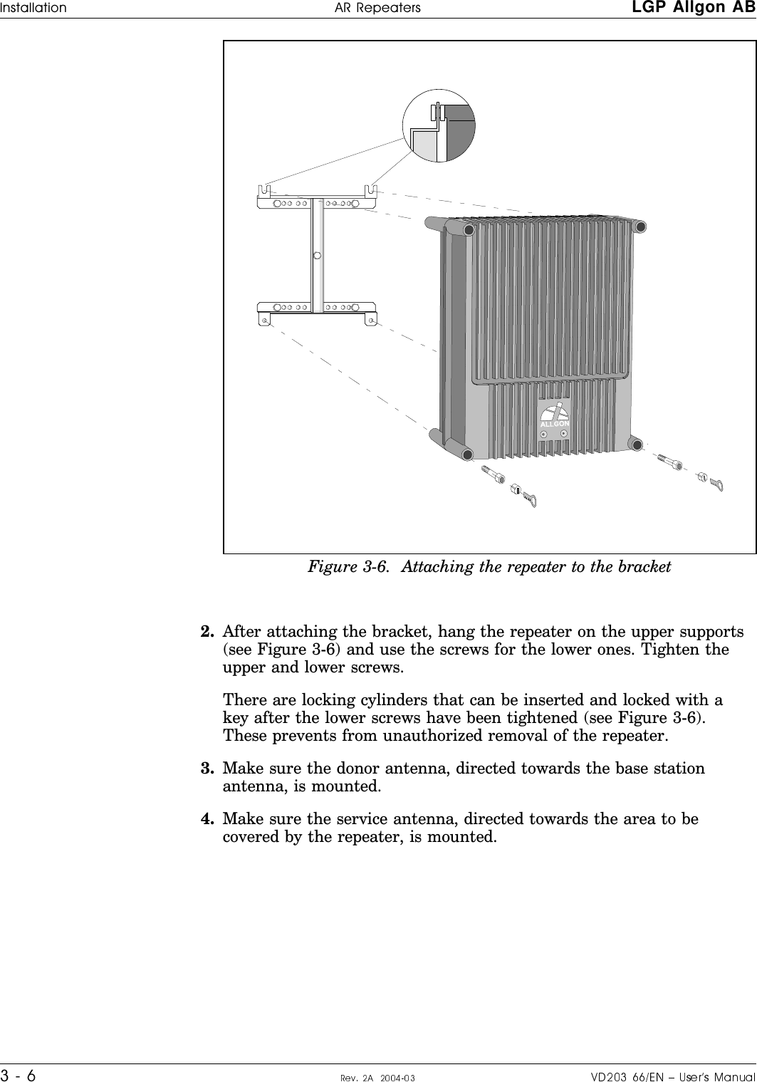
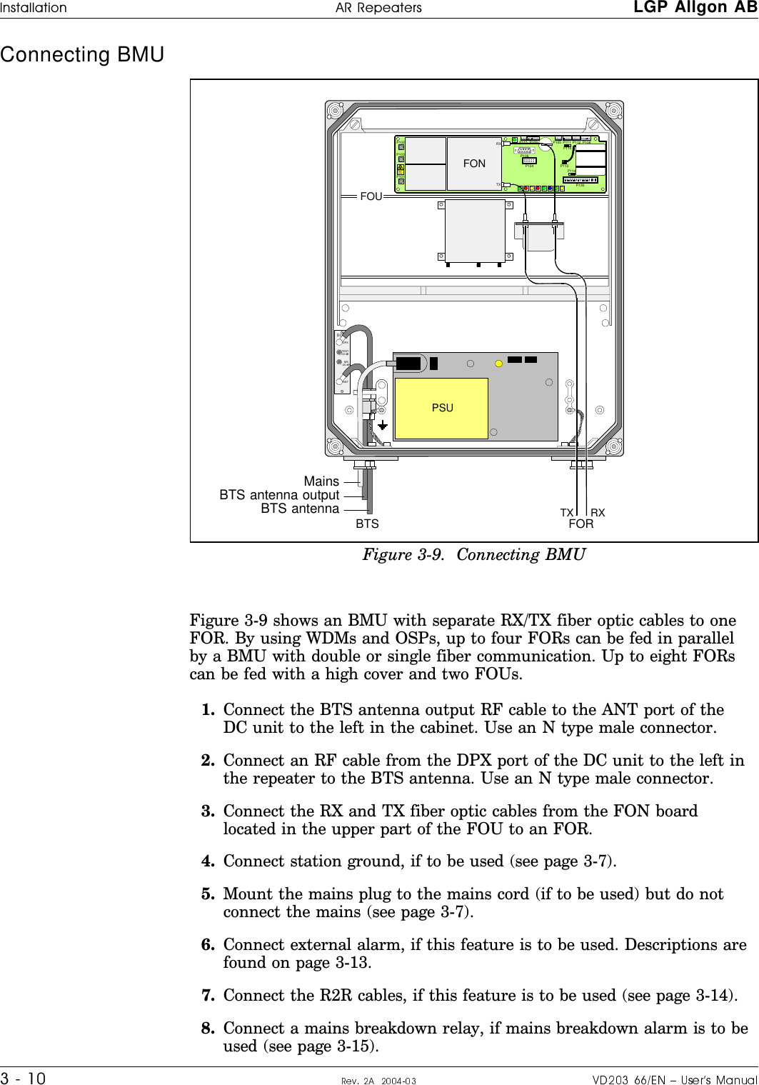
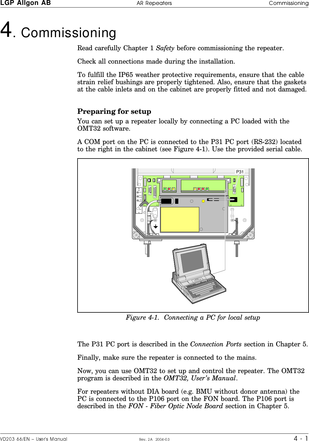
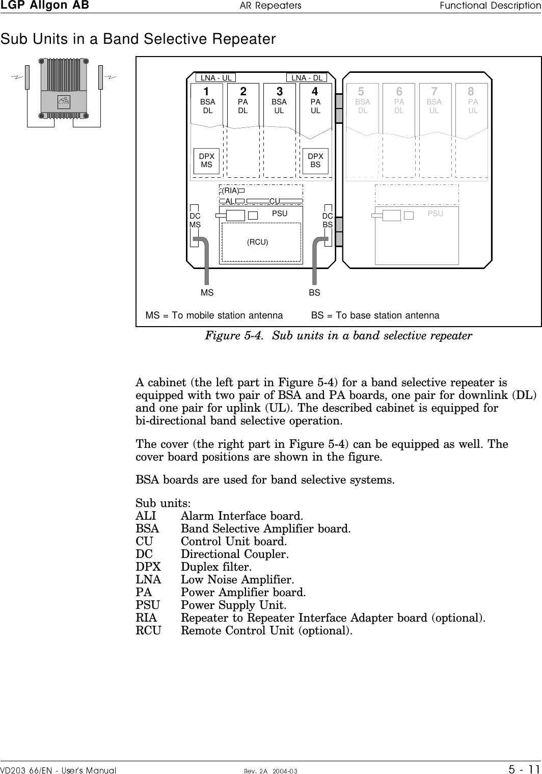
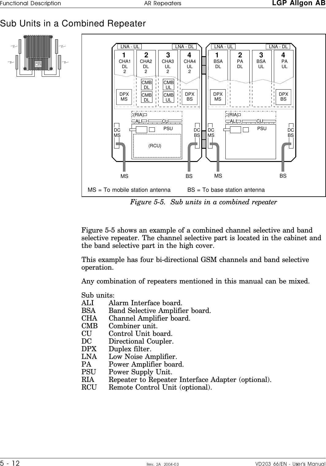
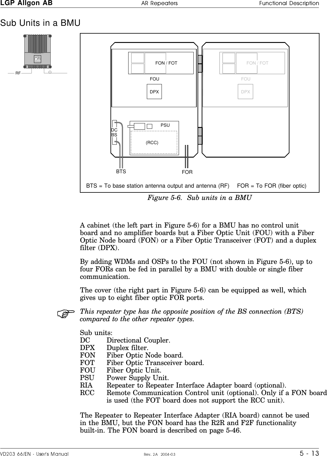
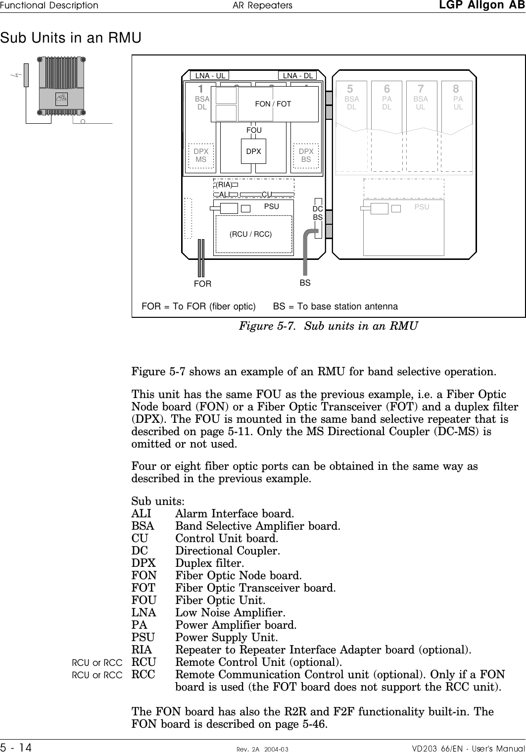
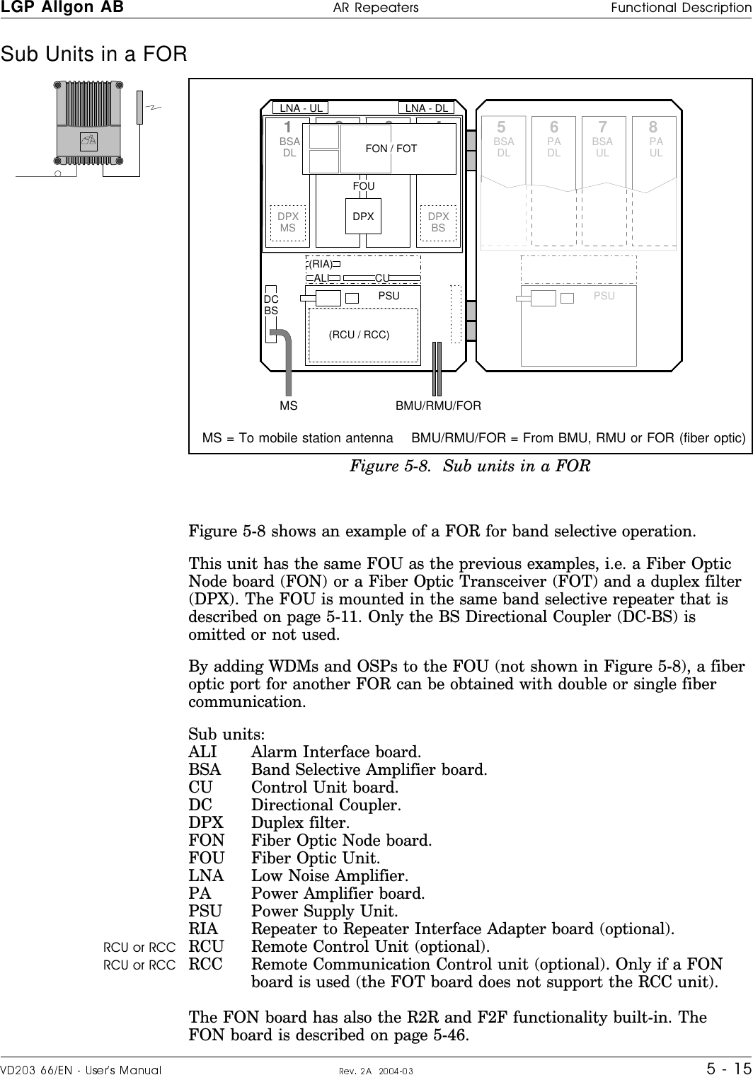
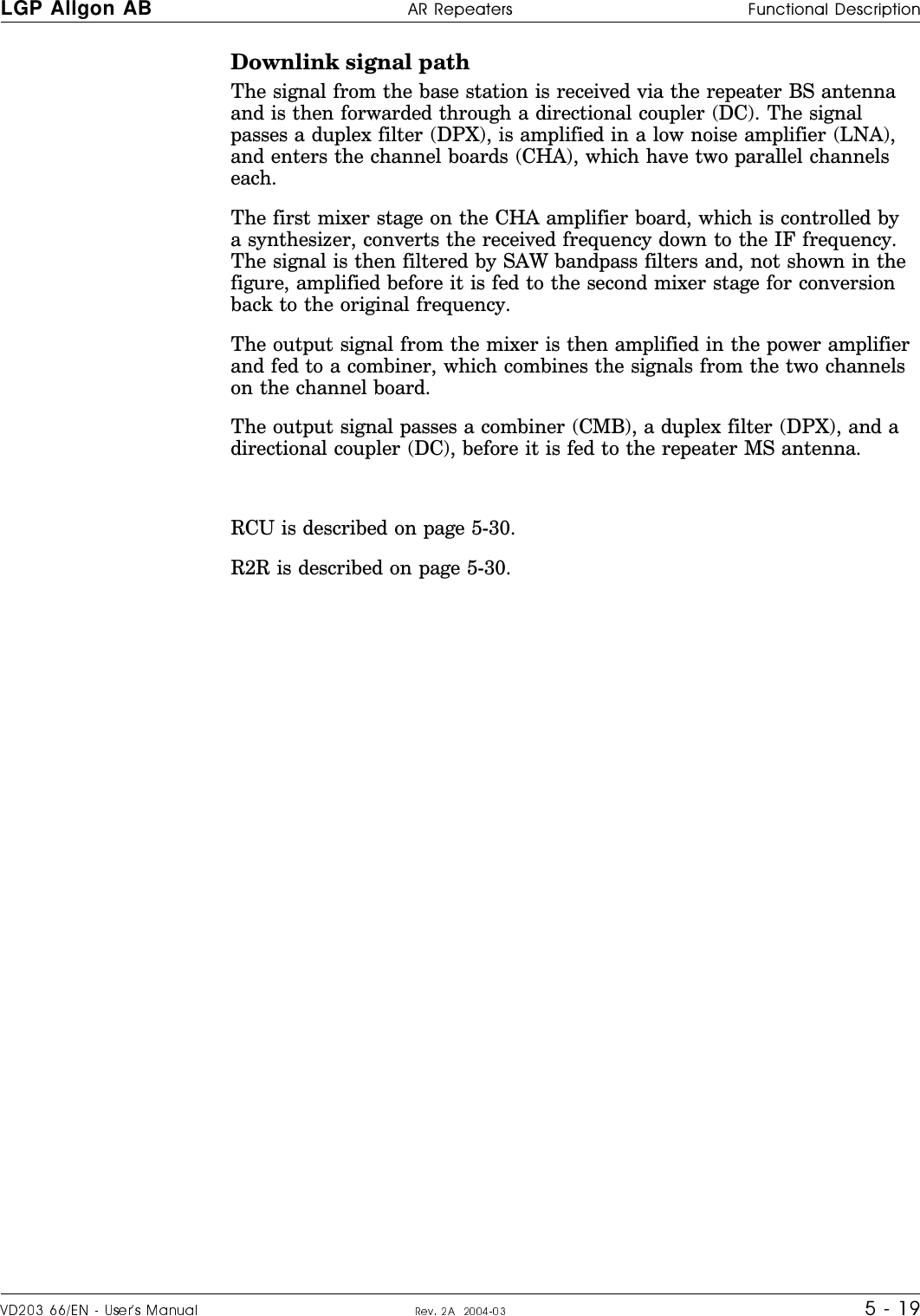
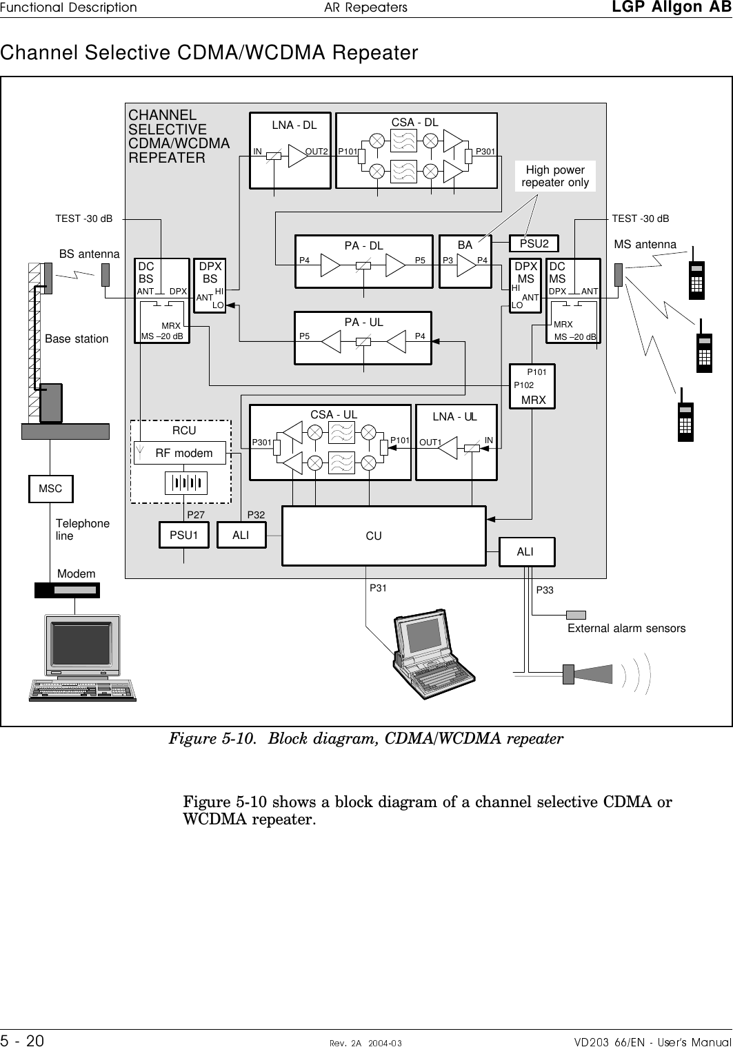
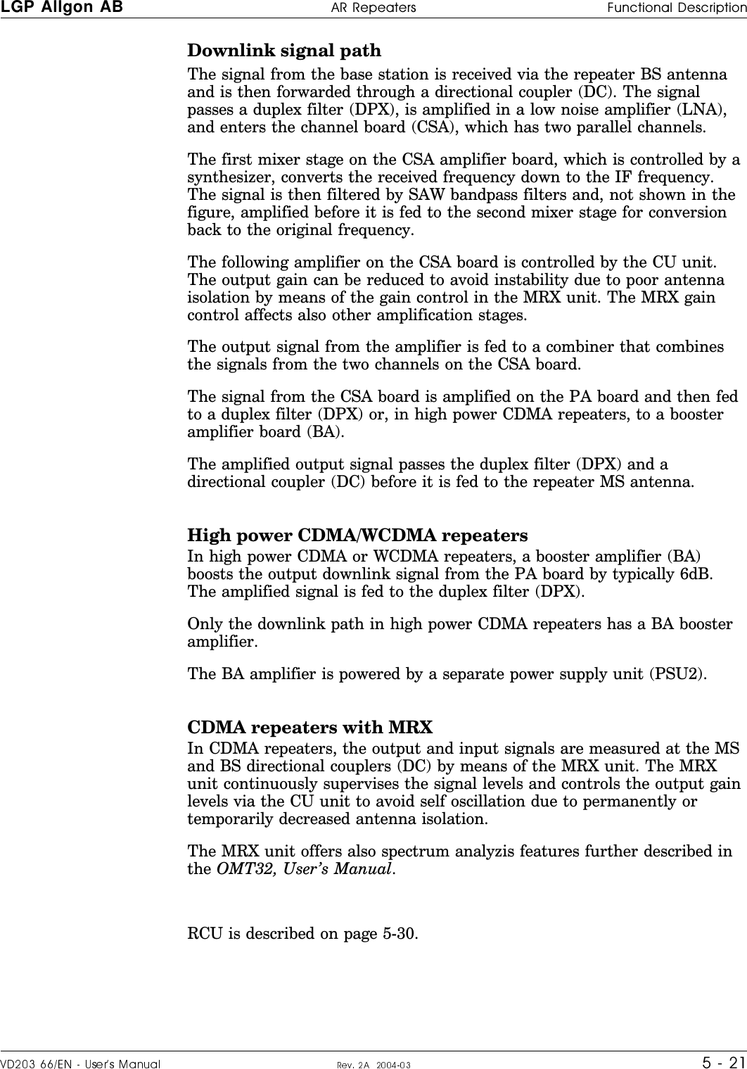
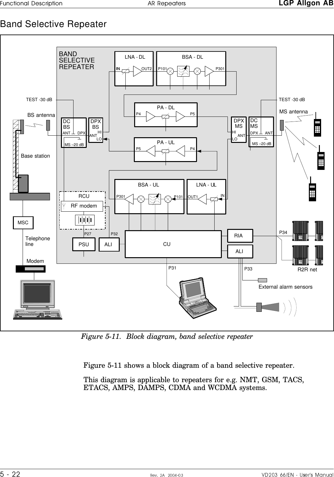
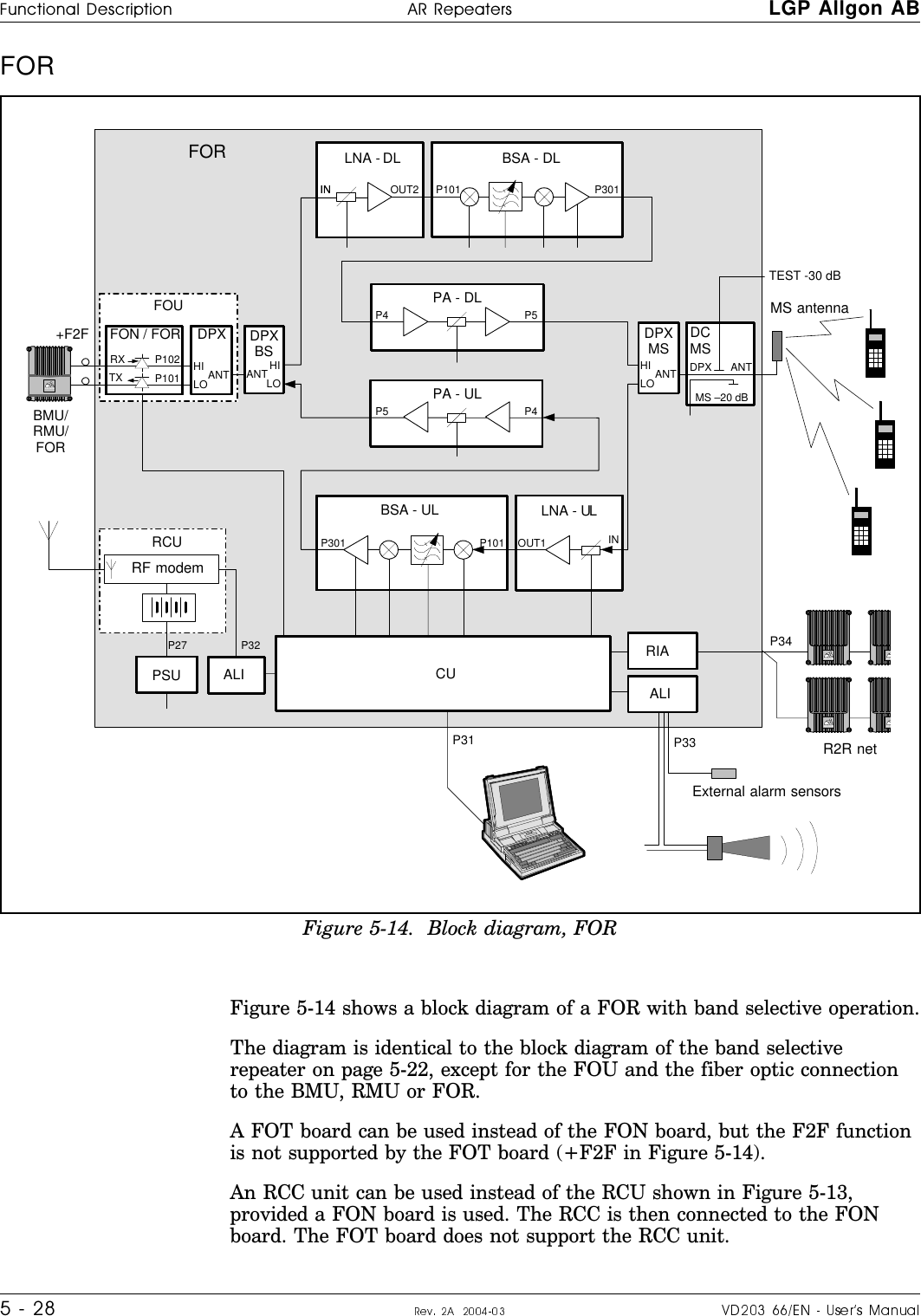
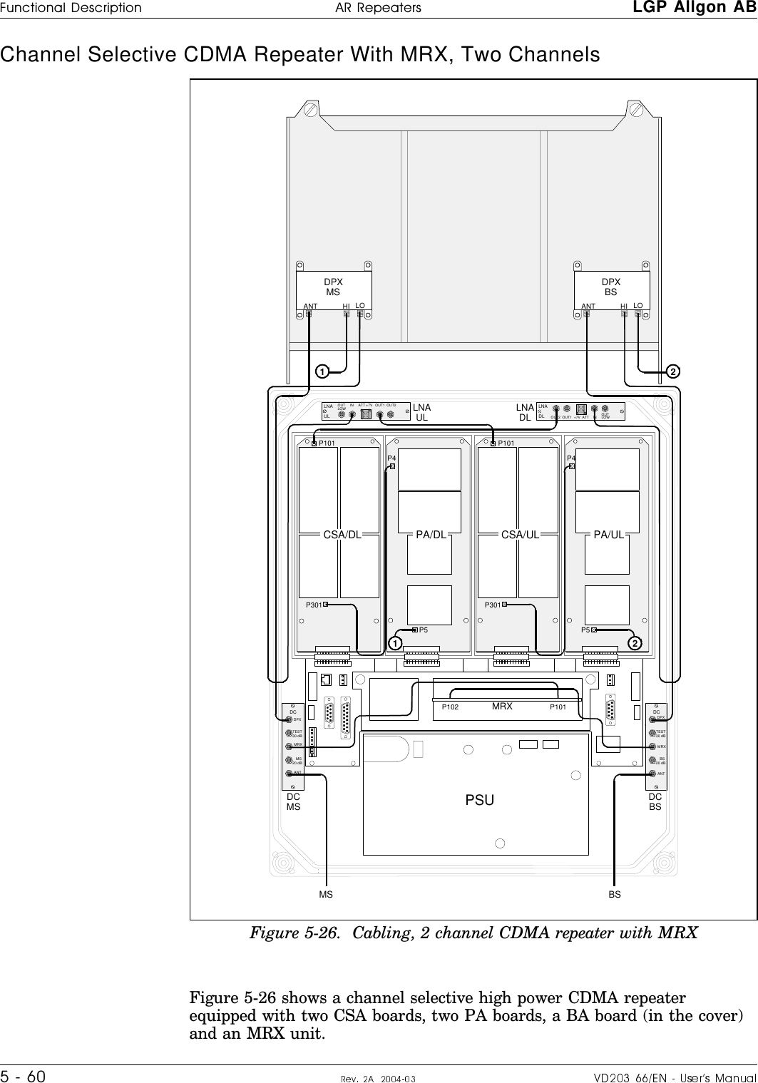
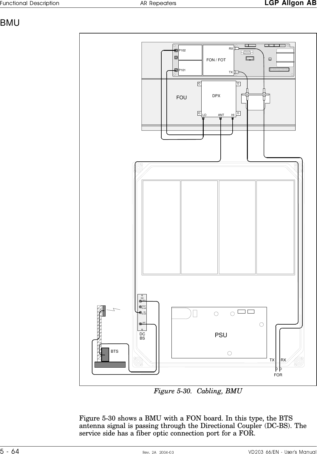
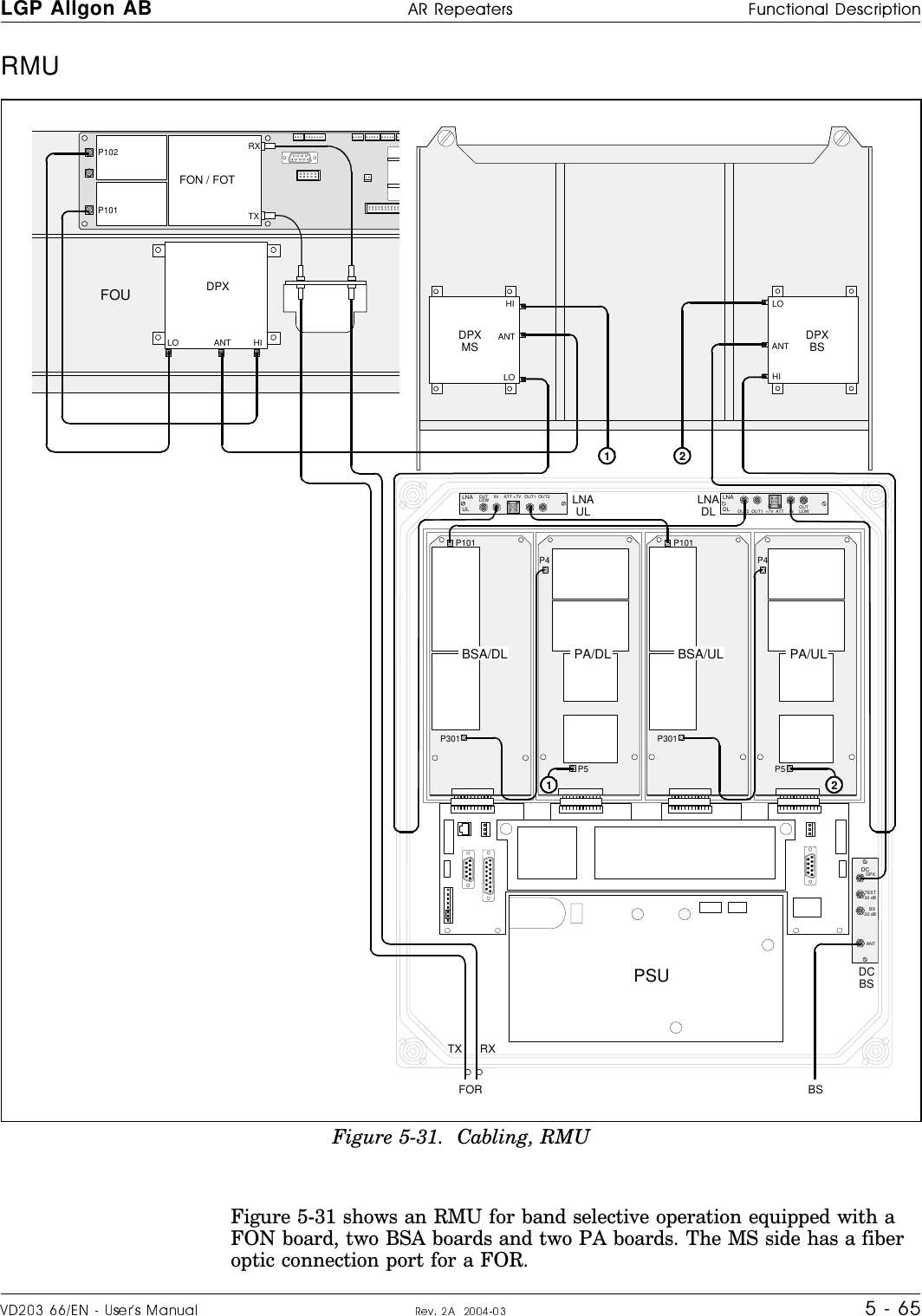
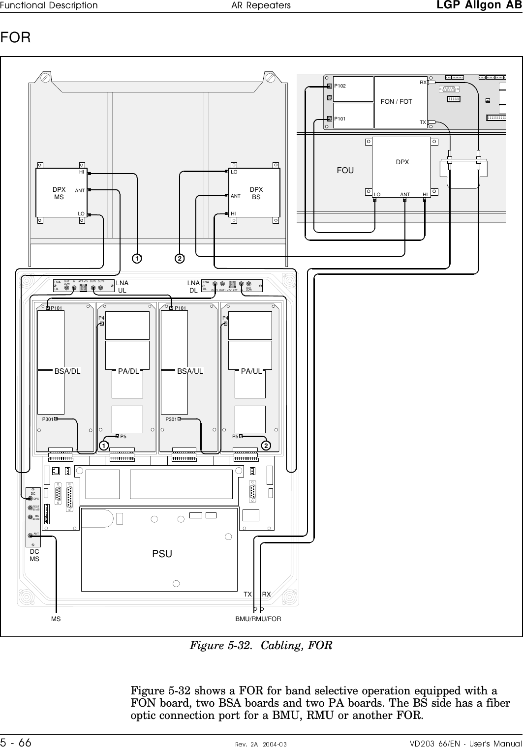
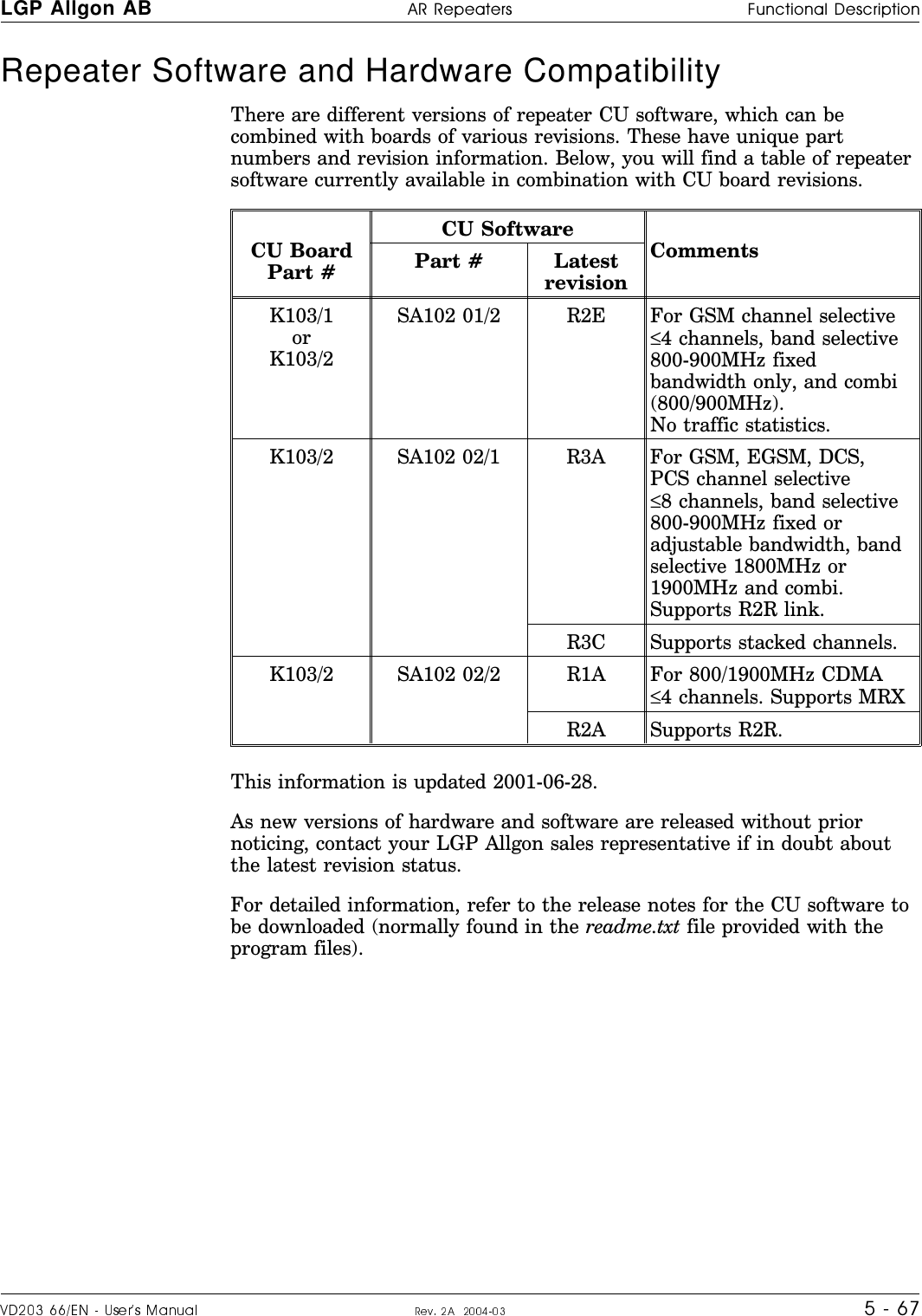
![LGP Allgon %66ITIEXIVW Safety1 - 11. Safety 3X^RS]MRKZ^O\^ROaY\Nt\OZOK^O\tSXMV_NO]KVV61:+VVQYX\OZOK^SXQ_XS^]]_MRK]\OZOK^O\]R_L]KXN\KNSYROKN]3^S]XOMO]]K\c^RK^KXcZO\]YXXOVSX`YV`ONSXSX]^KVVK^SYXYZO\K^SYXY\]O\`SMOYP_XS^]SXMV_NONSXKX61:+VVQYX\OZOK^O\]c]^OW_XNO\]^KXNKXNPYVVYa^ROLOVYaZYSX^]w>RO61:+VVQYX\OZOK^O\]K\ONO]SQXON^Y\OMOS`OKXNKWZVSPc]SQXKV]P\YWYXOY\WY\OLK]O]^K^SYX]KXN\O^\KX]WS^^RO]SQXKV]^YYXOY\WY\OWYLSVO]^K^SYX]+XNKV]Y^YKM^^ROY^RO\aKc\Y_XN^RK^S]^Y\OMOS`O]SQXKV]P\YWYXOY\WY\OWYLSVO]^K^SYX]KWZVSPcKXN\O^\KX]WS^^RO]SQXKV]^Y^ROLK]O]^K^SYX]61:+VVQYX\OZOK^O\]c]^OW]W_]^LO_]ONObMV_]S`OVcPY\^RS]Z_\ZY]OKXNXY^RSXQOV]Ow?XS^]]_ZZVSONP\YW^ROWKSX]W_]^LOMYXXOM^ON^YQ\Y_XNONY_^VO^]KXNSXMYXPY\WS^caS^R^ROVYMKVZ\O]M\SZ^SYX] w:YaO\]_ZZVc_XS^]]_ZZVSONP\YW^ROWKSX]MYX^KSXNKXQO\Y_]`YV^KQO^RK^MKXMK_]OOVOM^\SM]RYMU.S]MYXXOM^^ROWKSX]Z\SY\^YKXcaY\USX]_MRK_XS^6YMKV\OQ_VK^SYX]K\O^YLOPYVVYaONaROX]O\`SMSXQ]_MR_XS^]+_^RY\SdON]O\`SMOZO\]YXXOVYXVcK\OKVVYaON^Y]O\`SMO_XS^]aRSVO^ROWKSX]S]MYXXOM^ONw>RO\OZOK^O\MY`O\W_]^LO]OM_\ONSXYZOXONZY]S^SYXPY\SX]^KXMOLc^cSXQS^_ZK^Y_^NYY\\OZOK^O\aY\U9^RO\aS]O^ROMY`O\MKXLOMVY]ONLc^ROaSXNKXNMK_]OcY_\PSXQO\]QO^^SXQZSXMRONY\cY_\ROKNLOSXQRS^wAROXaY\USXQYXK\OZOK^O\YXRSQRQ\Y_XNPY\SX]^KXMOYXKWK]^Y\ZYVOLOMK\OP_VXY^^YN\YZZK\^]Y\^ROOX^S\O\OZOK^O\0KVVSXQZK\^]MKXMK_]O]O\SY_]ZO\]YXKVSXT_\cw+VV<0^\KX]WS^^SXQ_XS^]SXMV_NSXQ\OZOK^O\]aSVVQOXO\K^O\KNSY]SQXKV]KXN^RO\OLcQS`O\S]O^YOVOM^\YWKQXO^SMPSOVN]^RK^WKcLORKdK\NY_]^Y^ROROKV^RYPKXcZO\]YXaRYS]Ob^OX]S`OVcObZY]ONMVY]O^YKXKX^OXXK=OO^RO2_WKX/bZY]_\OYP<0<KNSK^SYX]OM^SYXYXZKQO Beryllium oxide w,O\cVVS_WYbSNO,O9WKcLOMYX^KSXONSXZYaO\NO`SMO]PY\SX]^KXMOSXN_WWcVYKN]SXNS\OM^SYXKVMY_ZVO\].--SXMYWLSXO\_XS^]-7,KXNSXK^^OX_K^Y\]YX^RO098LYK\N,O\cVVS_WYbSNOS]ZYS]YXY_]SPZ\O]OX^K]N_]^Y\]WYUO^RK^MKXLOSXRKVON.YXY^PSVOQ\SXNWKMRSXOY\^\OK^^RO]OZK\^]aS^RKMSNHydrogen fluoride w-YKbSKVMKLVO]_]ONSXWKXc61:+VVQYX]c]^OW]RK`O^ROSX]_VK^SYXWKNOYP:>0/ZYVc^O^\KPV_Y\YO^RcVOXO^RK^QS`O]YPP]WKVVKWY_X^]YPRcN\YQOXPV_Y\SNOaROXROK^ON2cN\YQOXPV_Y\SNOS]ZYS]YXY_].YXY^_]OROK^SXQ^YYV]aROX]^\SZZSXQYPPMYKbSKVMKLVOSX]_VK^SYX8YZK\^SM_VK\WOK]_\O]K\O^YLO^KUOXSXMK]OYPPS\OLOMK_]O^ROOWS^^ONMYXMOX^\K^SYXYPRcN\YQOXPV_Y\SNOS]`O\cVYa](https://usermanual.wiki/Powerwave-Technologies/AR4240.User-Manual-part-1/User-Guide-453031-Page-13.png)
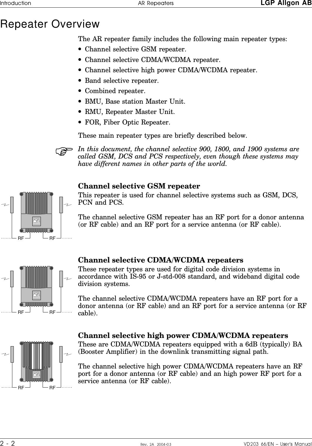
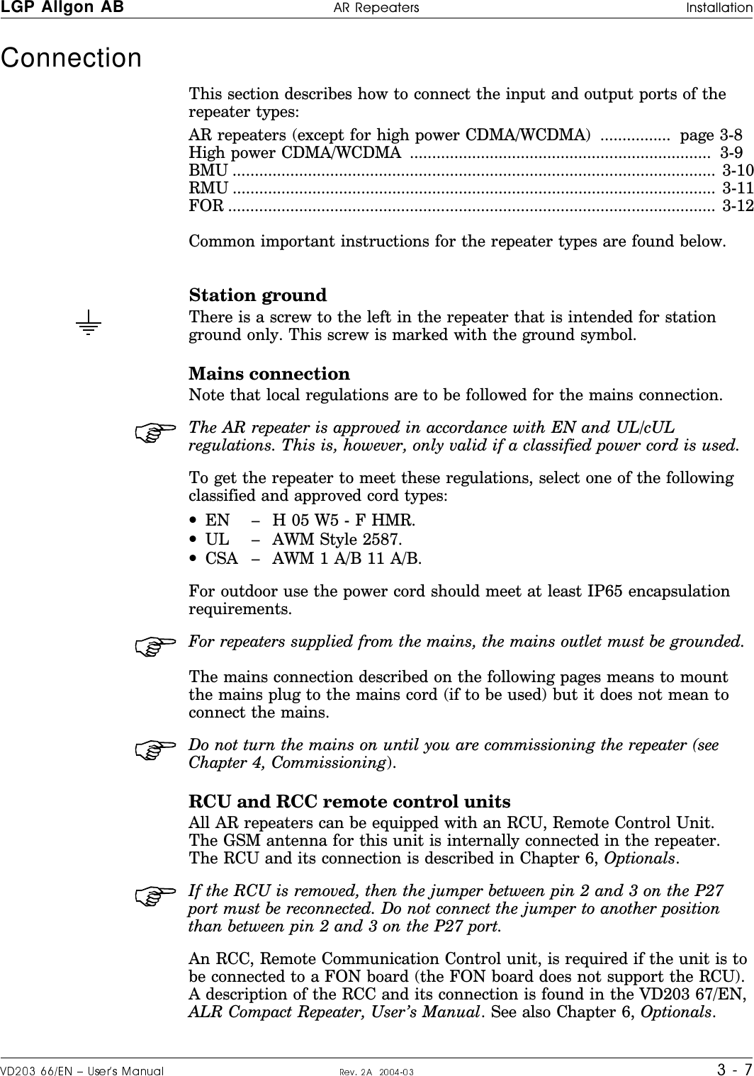
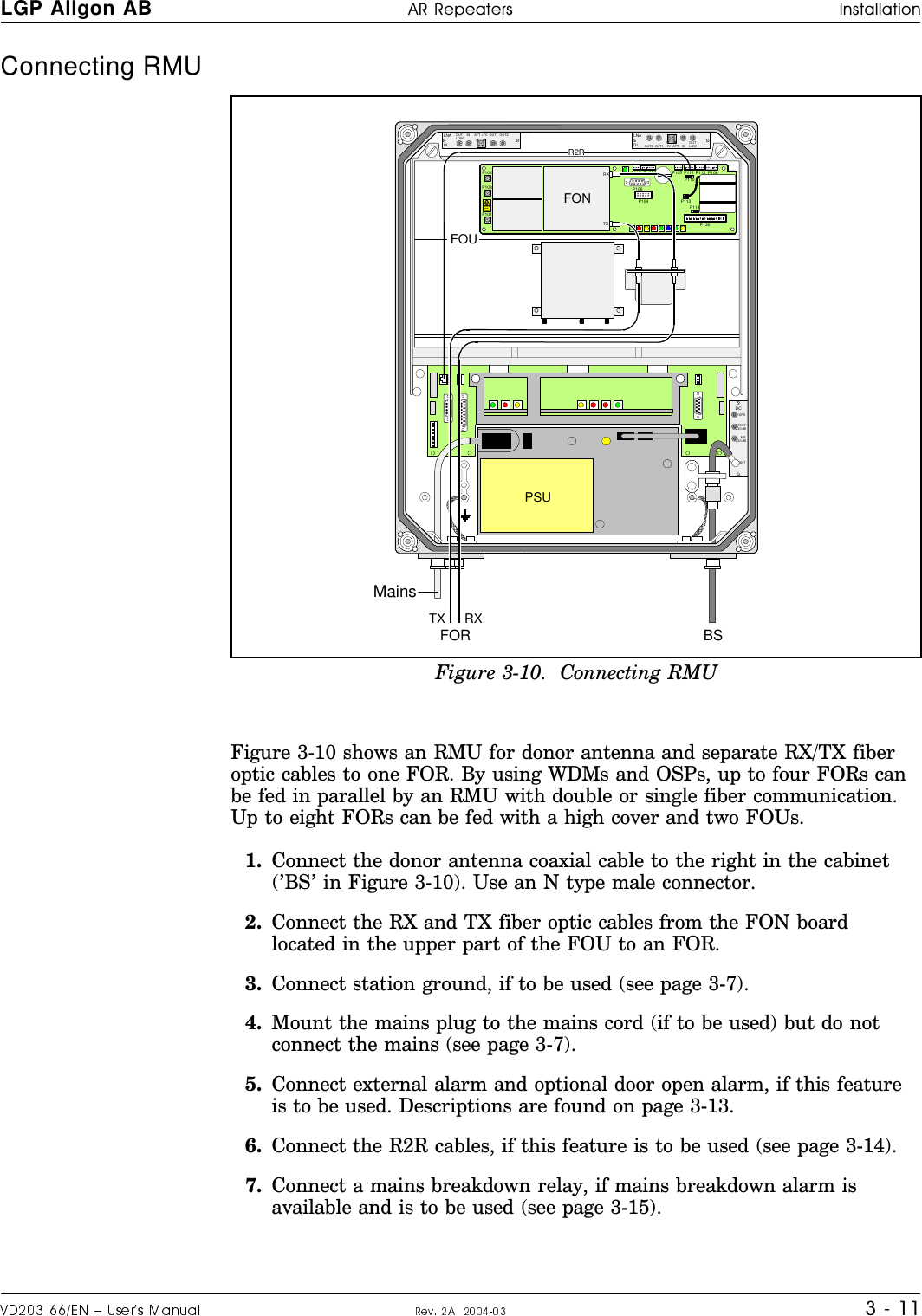
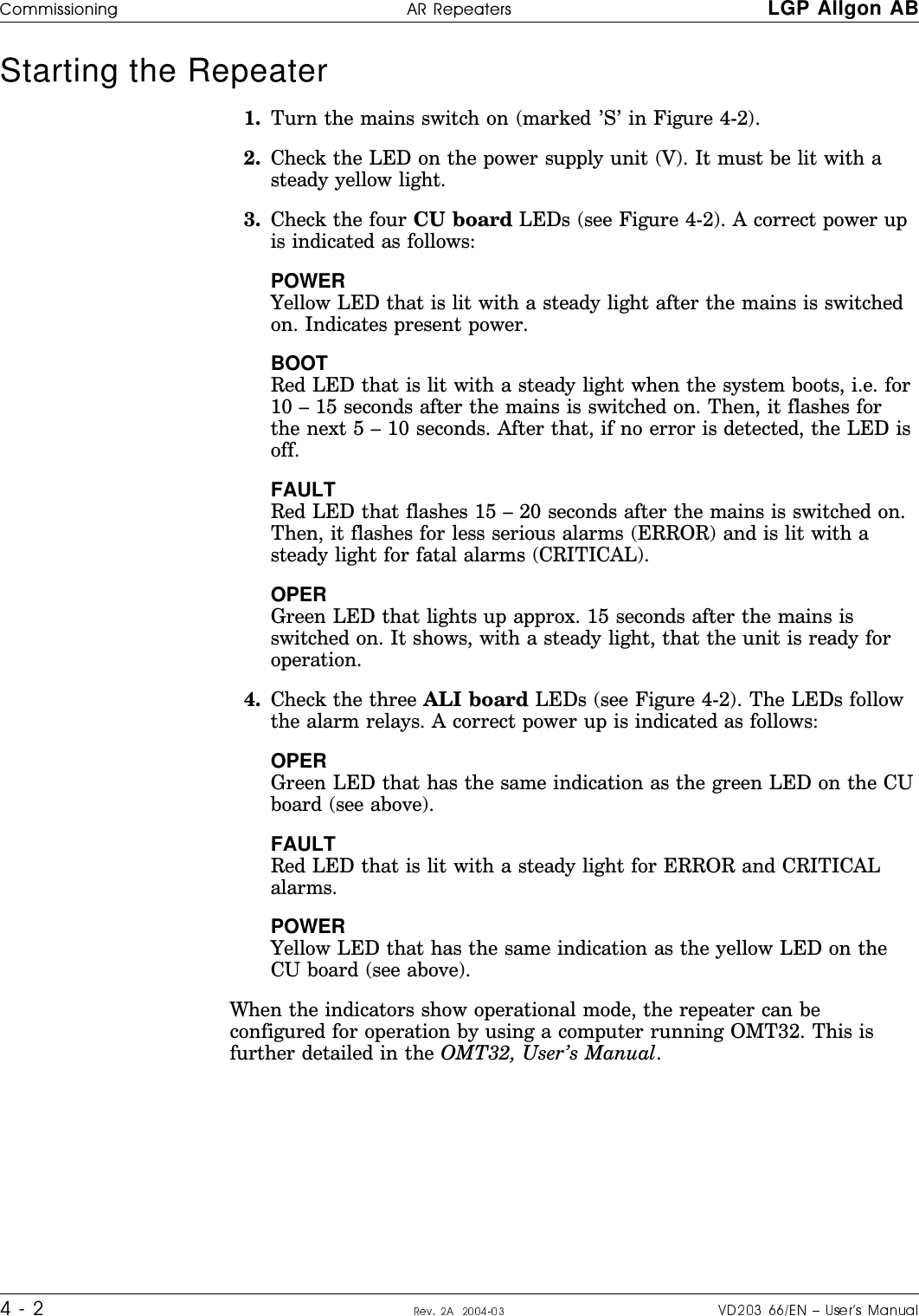
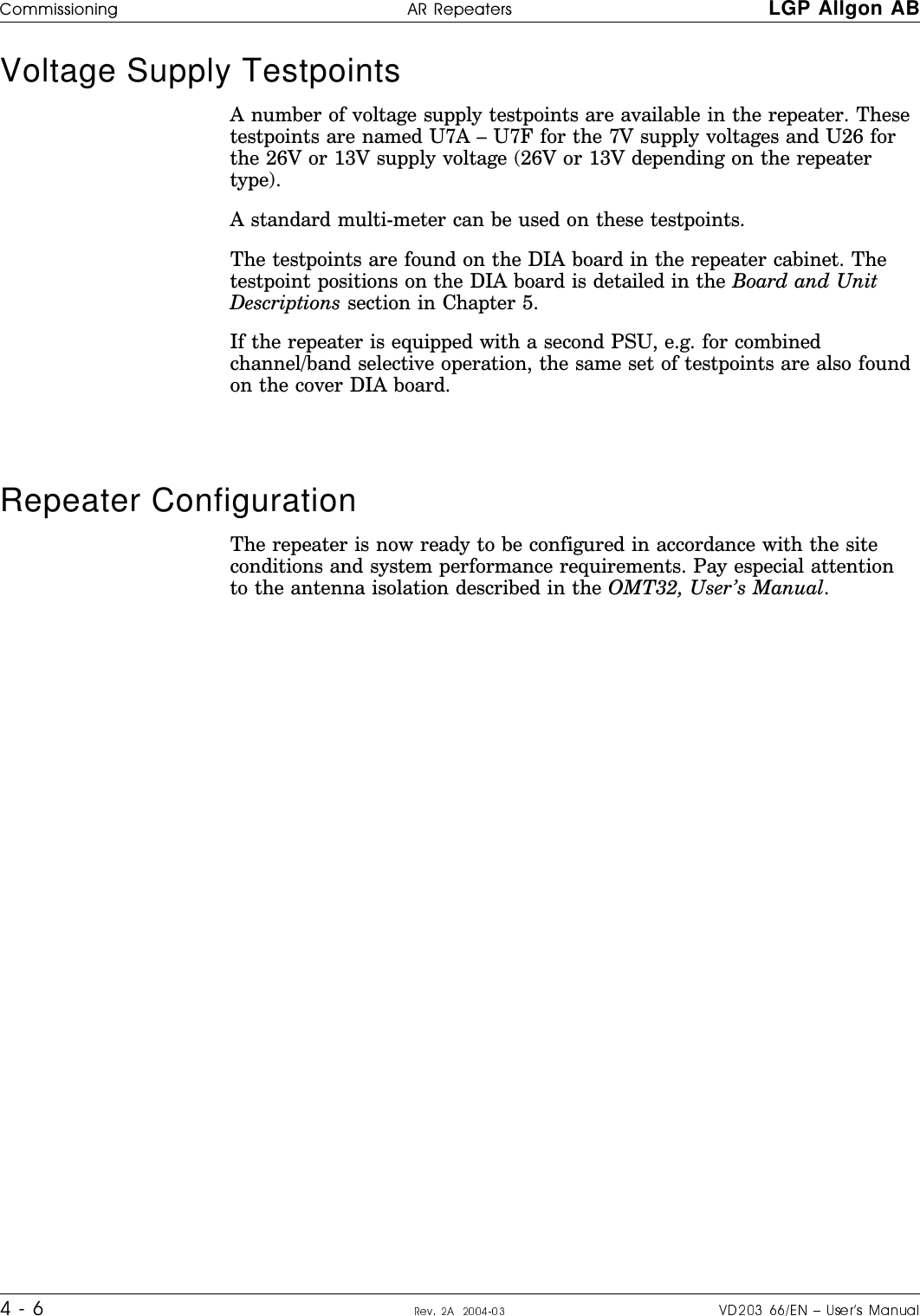
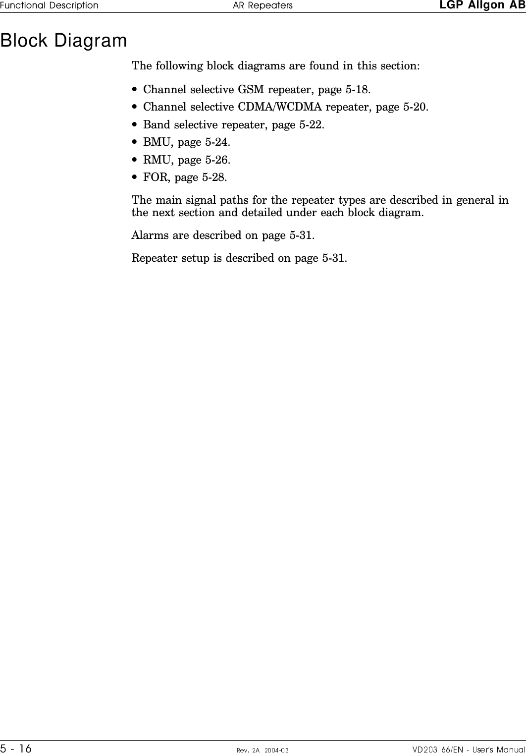
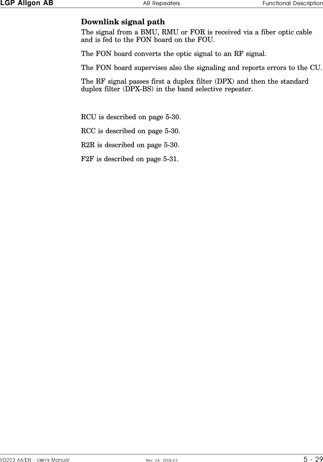
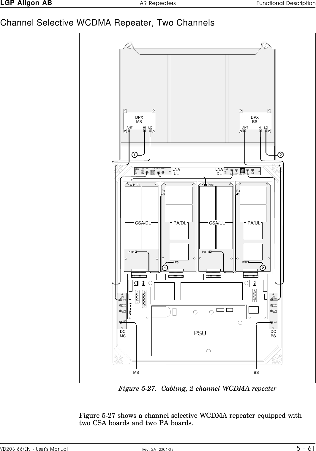
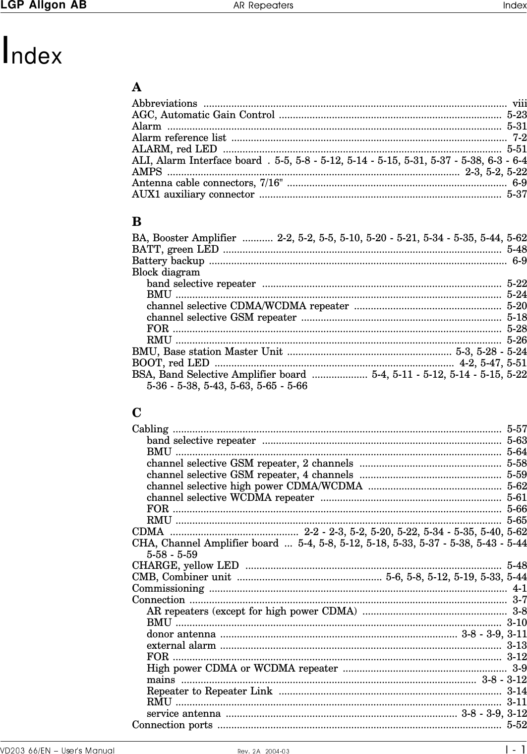
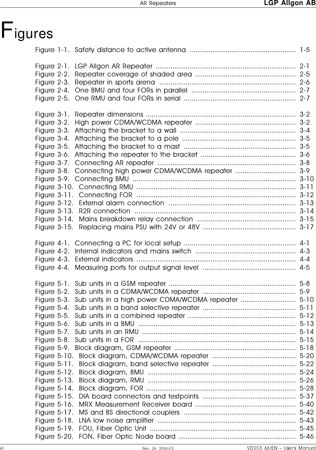
![Safety %66ITIEXIVW LGP Allgon1 - 2 w+VS^RS_WLK^^O\cS]ZO\WKXOX^VcWY_X^ONSX\OZOK^O\-?_XS^]KXNSX098KXN9-7_XS^]._O^Y^RO\S]UYPObZVY]SYX^RS]LK^^O\cW_]^YXVcLO\OWY`ONP\YW^ROLYK\NLcKX61:+VVQYXK_^RY\SdON]O\`SMO^OMRXSMSKXw8S-NLK^^O\SO]K\OWY_X^ONYX^RO098_XS^>RO]OLK^^O\SO]MYX^KSXOX`S\YXWOX^KVZYS]YXY_]]_L]^KXMO]3P\OZVKMON^ROYVNLK^^O\SO]]RY_VNLO^KUOXMK\OYPK]]^K^ONSX^ROVYMKVZ\O]M\SZ^SYX] w>RO098_XS^MYX^KSX]KMVK]] 333LVK]O\^\KX]WS^^O\^RK^OWS^] xWASX`S]SLVOVK]O\\KNSK^SYXN_\SXQYZO\K^SYX+`YSNNS\OM^ObZY]_\OP\YW_XMYXXOM^ONVK]O\^\KX]WS^^O\Y\PSLO\MY\NK]PYVVYa]$x .YXY^ZYaO\_Z^RO098_XS^SPKPSLO\MKLVOS]XY^K^^KMRON^Y^ROPSLO\Y_^Z_^?6ZY\^XOS^RO\SPKPSLO\MKLVOS]K^^KMRON^Y^ROZY\^L_^_XK^^KMRONSX^ROY^RO\OXNx 8O`O\VYYUSX^ROOXNYPKPSLO\MKLVO>ROXWKXNXWVK]O\VSQR^S]XY^`S]SLVO]YXY]SQXKVSNOX^SPSMK^SYXMKXLOWKNOKXcaKc?]OKVaKc]KXSX]^\_WOX^]_MRK]KZYaO\WO^O\^YNO^OM^]SQXKVSXQx 8O`O\_]OKXcUSXNYPWKQXSPcSXQNO`SMO]^RK^MKXPYM_]^ROVK]O\VSQR^^YKX_XKSNONOcOWarning Signs>ROPYVVYaSXQaK\XSXQ]SQX]W_]^LOYL]O\`ONKXNLOUOZ^MVOKXKXN\OKNKLVO,O\cVVS_WYbSNO>RS]aK\XSXQ]SQXS]KZZVSONYXLYK\N]KXN_XS^]aRSMRMYX^KSXLO\cVVS_WYbSNOZK\^]>RS]aK\XSXQ]SQXS]KZZVSONK^^ROLY^^YWSX]SNO^ROMKLSXO^LOVYa^ROZYaO\]_ZZVc_XS^>ROZ\O`SY_]]OM^SYXNO^KSV]ZK\^]MYX^KSXSXQLO\cVVS_WYbSNOKXNRYa^YK`YSNNKXQO\Y_]NOKVSXQaS^R^RO]OZK\^]BerylliumoxidehazardBERYLLIUM OXIDE(Toxic)used in equipmentsee instruction book](https://usermanual.wiki/Powerwave-Technologies/AR4240.User-Manual-part-1/User-Guide-453031-Page-14.png)
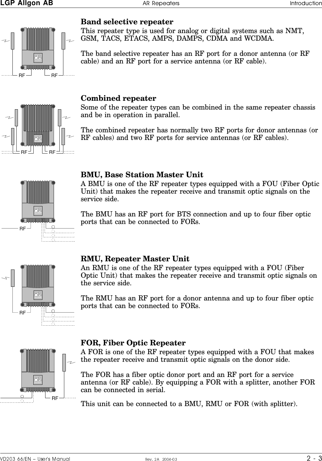
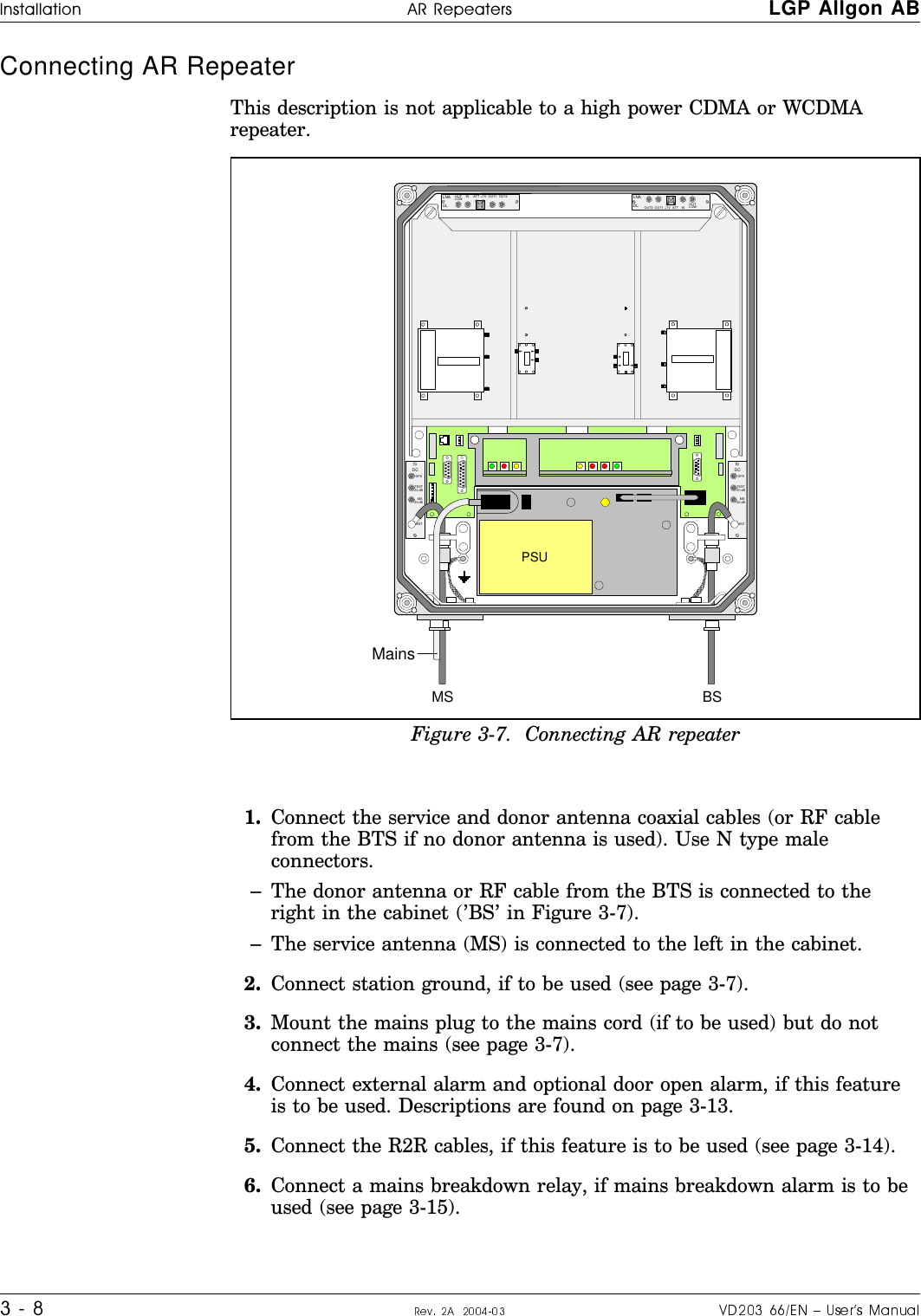
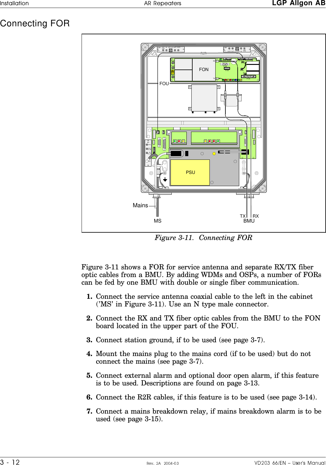
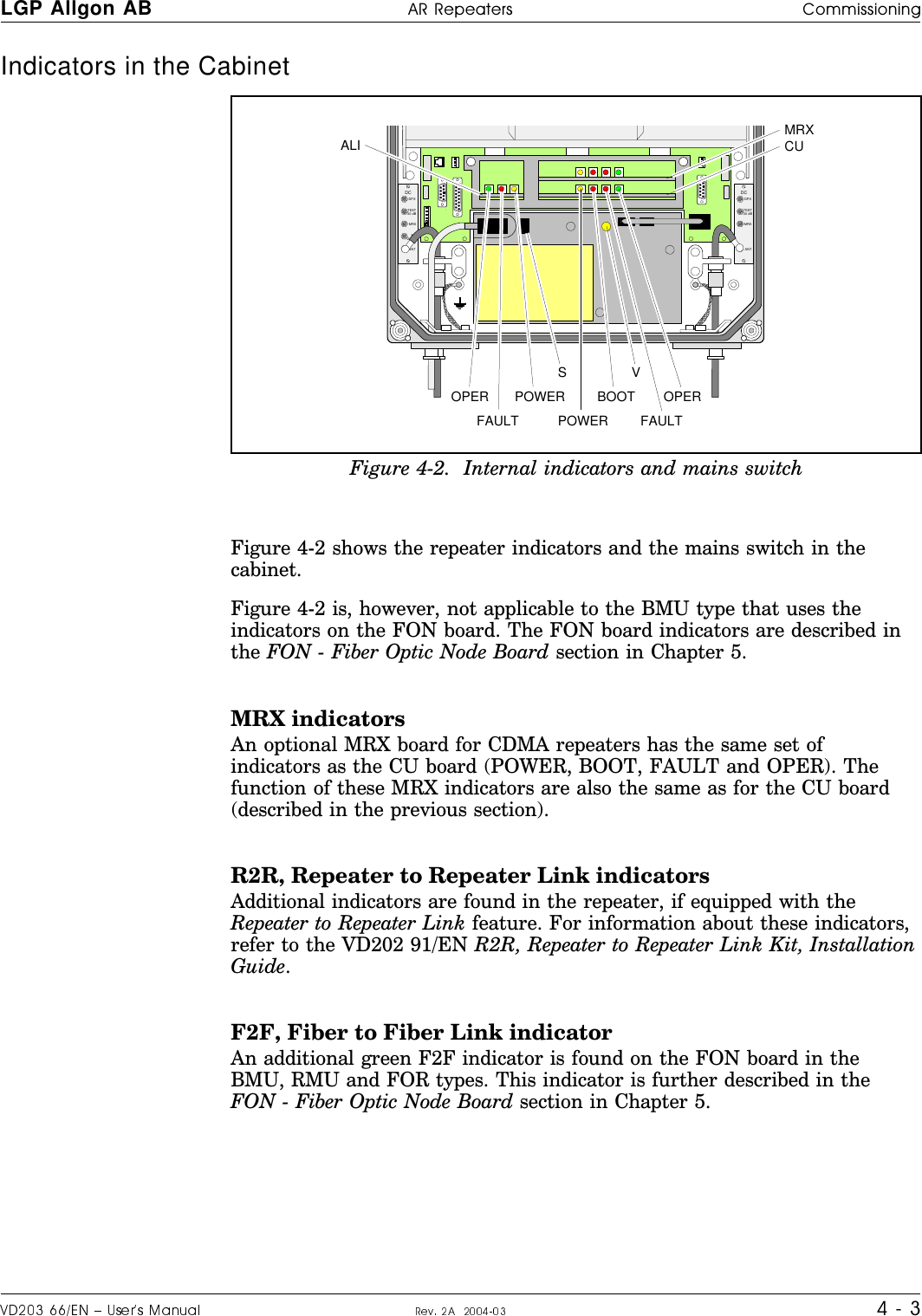
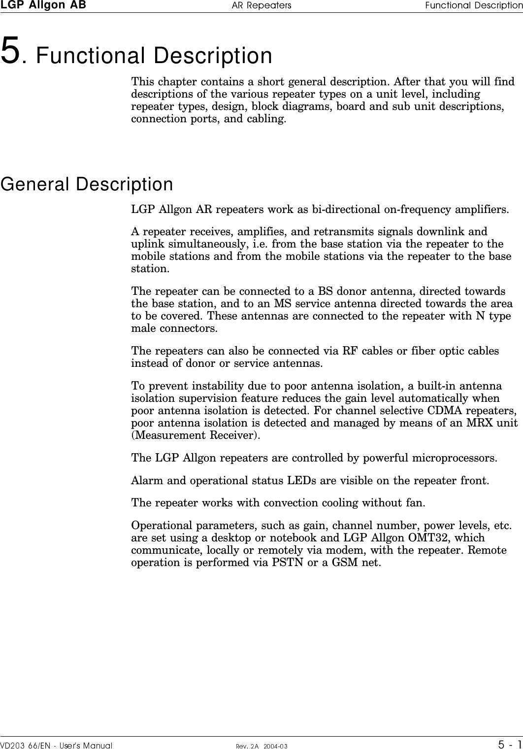
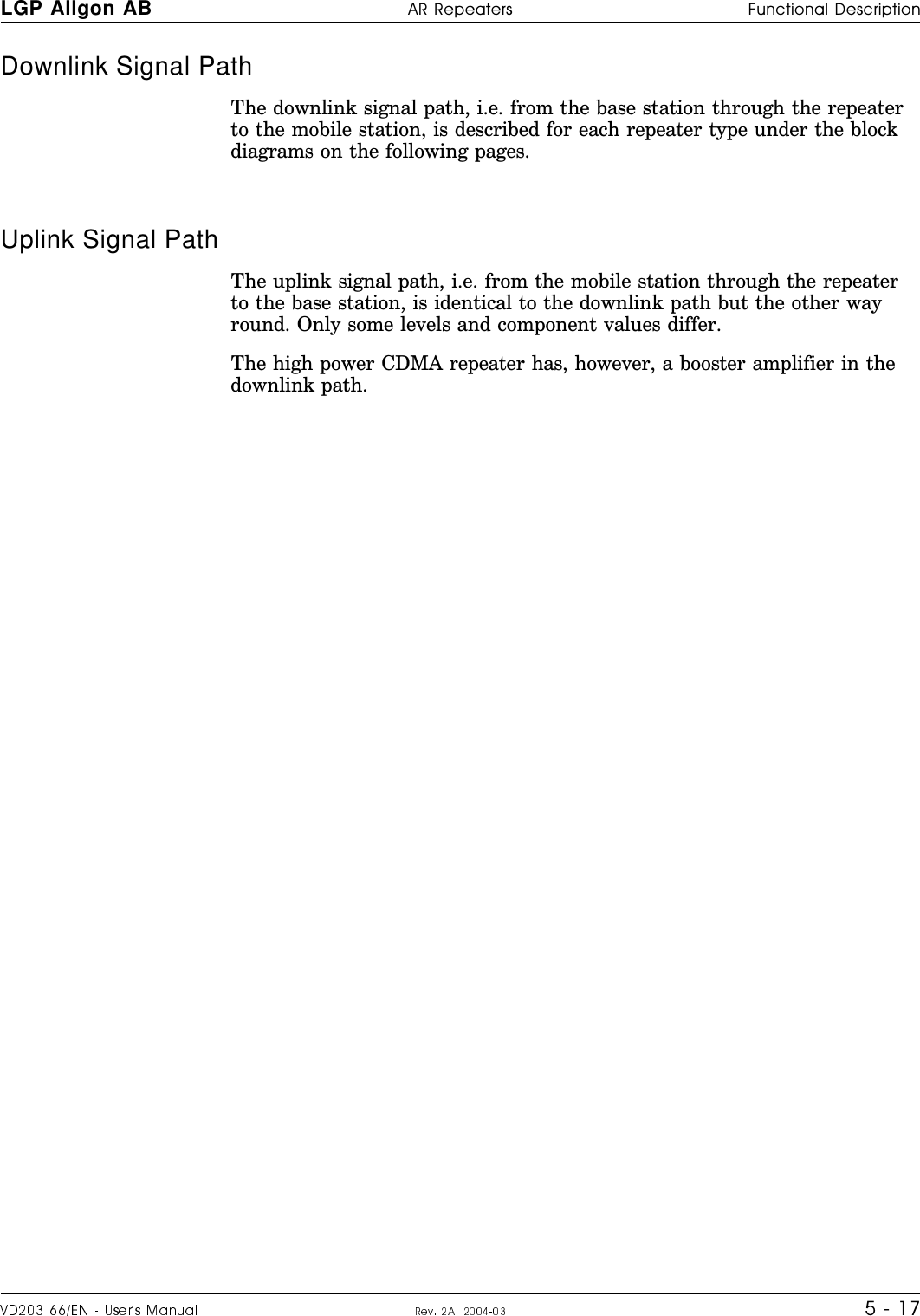
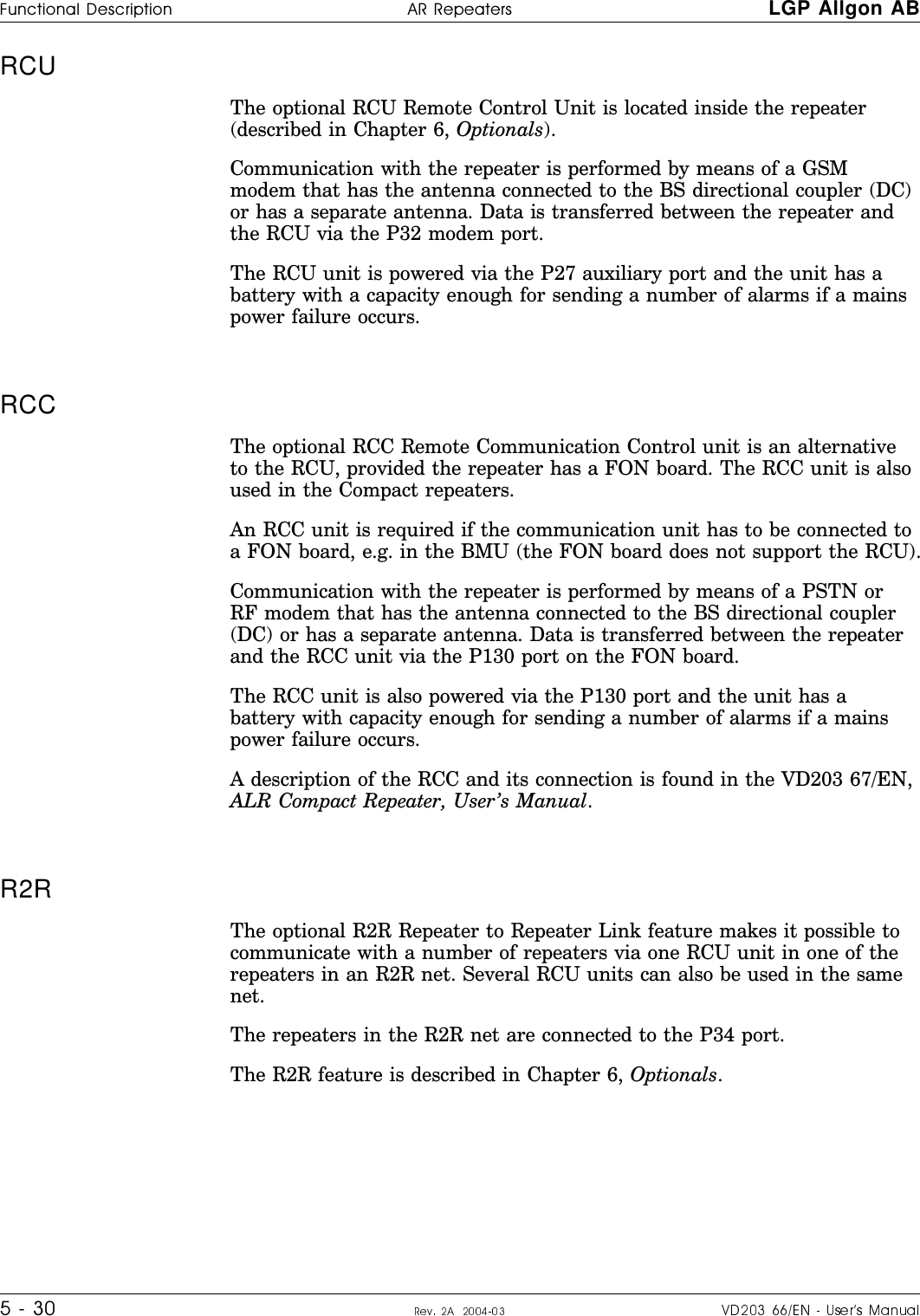
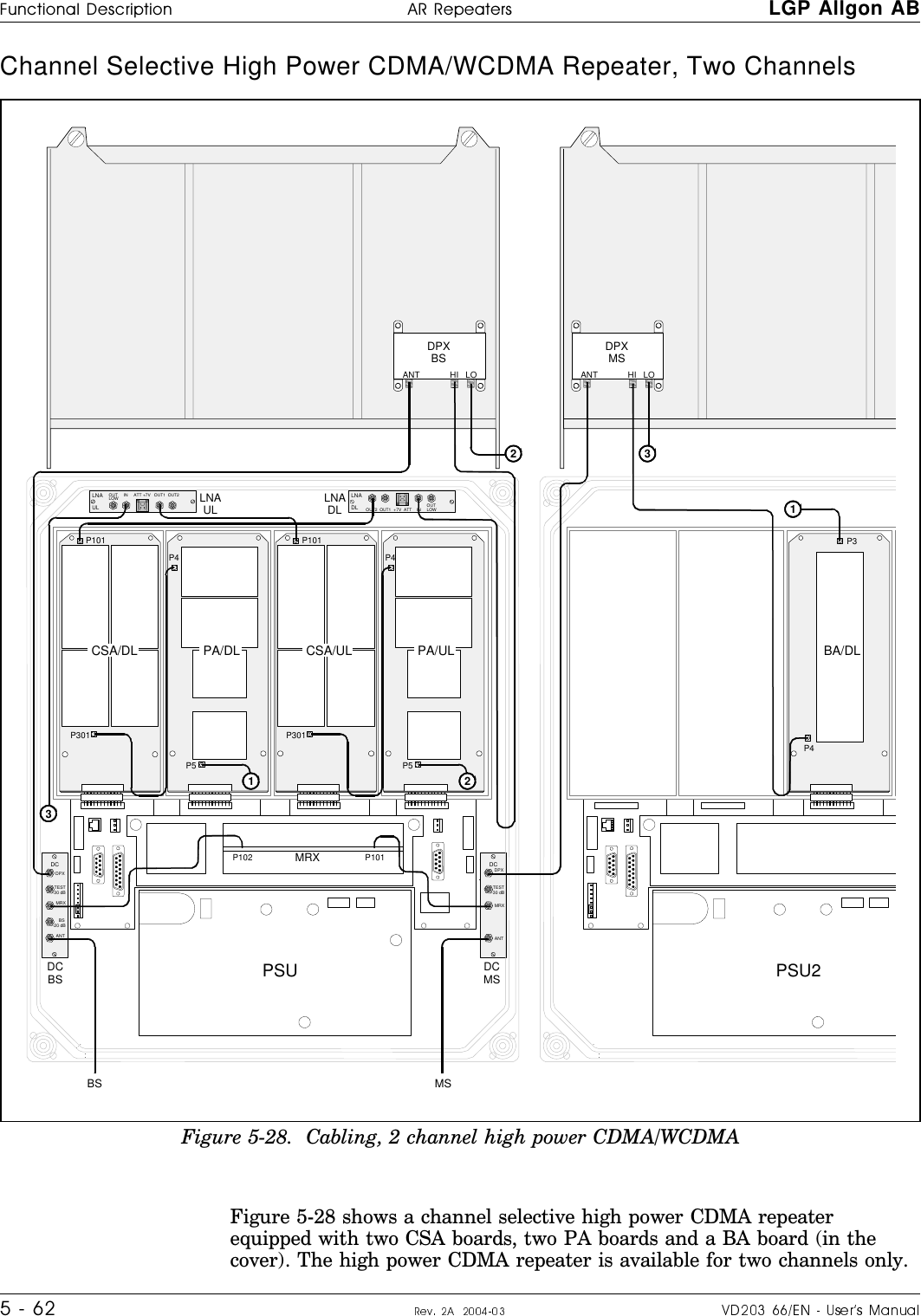
![LGP Allgon %66ITIEXIVW Safety1 - 3Human Exposure of RF Radiation>RS]]OM^SYXMYX^KSX]KPOaaY\N]KLY_^\OZOK^O\KX^OXXK]KXNZ\O]M\SZ^SYX]PY\SX]^KVVK^YXKXNWKSX^OXKXMOYPKX^OXXK]c]^OW]+V]YS^NO]M\SLO]RYa^YMKVM_VK^O]KPO^cNS]^KXMO]XOONONPY\<0\KNSK^SYXK^NSPPO\OX^KX^OXXKZYaO\KXNP\O[_OXMSO]Repeater Antennas>YLOKLVO^Y\OMOS`OKXN^\KX]WS^]SQXKV]K]NO]M\SLONSX^ROPS\]^L_VVO^ONZK\KQ\KZRYXZKQO K\OZOK^O\S]MYXXOM^ON^YKNYXY\KX^OXXKNS\OM^ON^YaK\N]^ROLK]O]^K^SYXKXNK]O\`SMOKX^OXXKNS\OM^ON^YaK\N]^ROMY`O\KQOK\OK+PSLO\YZ^SMMKLVOP\YW^ROLK]O]^K^SYXWSQR^RYaO`O\LO]_L]^S^_^ONPY\^RONYXY\KX^OXXKInstallation and Maintenance of Antenna Systems3X]^KVVK^SYXKXNWKSX^OXKXMOYPKVV\OZOK^O\KX^OXXK]c]^OW]W_]^LOZO\PY\WONaS^R\O]ZOM^^Y^RO\KNSK^SYXObZY]_\OVSWS^]PY\Z_LVSMK\OK]>ROKX^OXXK\KNSK^SYXVO`OVS]KPPOM^ONLc^RO\OZOK^O\Y_^Z_^ZYaO\^ROKX^OXXKQKSXKXNLc^\KX]WS]]SYXNO`SMO]]_MRK]MKLVO]MYXXOM^Y\]]ZVS^^O\]KXNPOONO\]2K`OKV]YSXWSXN^RK^^RO]c]^OWWSXSW_WMY_ZVSXQVY]]^cZSMKVLO^aOOXN,KXNN,S]NO^O\WSXONLcK]^KXNK\NaS^R^ROZ_\ZY]O^YZ\Y^OM^LK]O]^K^SYX]P\YWXYS]OKXNY^RO\ZO\PY\WKXMON\YZZSXQOPPOM^]](https://usermanual.wiki/Powerwave-Technologies/AR4240.User-Manual-part-1/User-Guide-453031-Page-15.png)
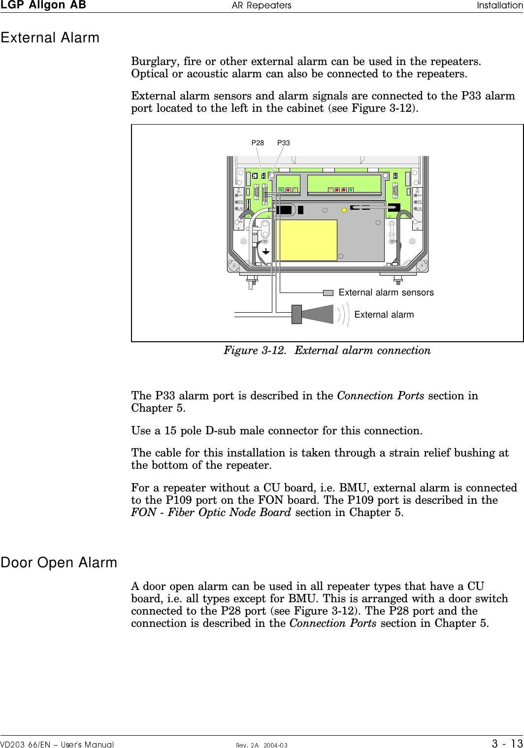
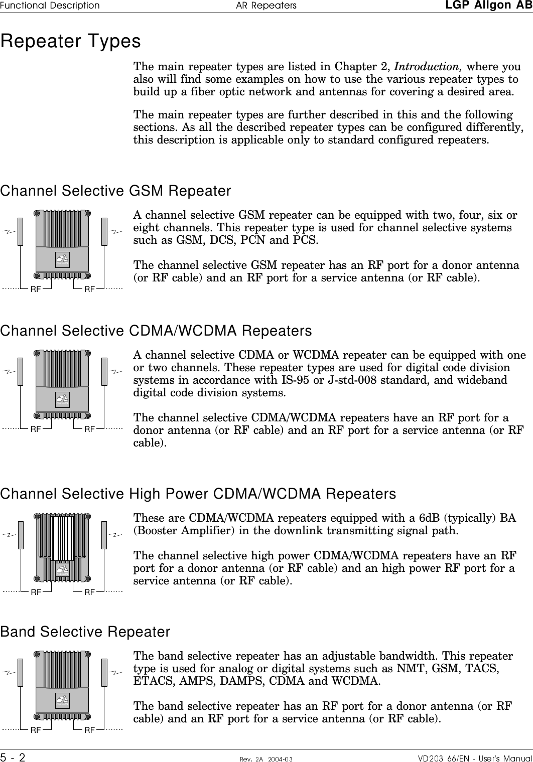
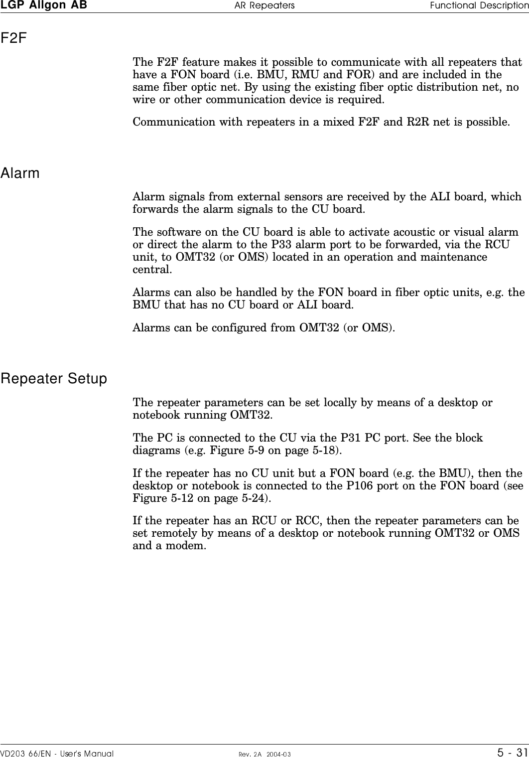
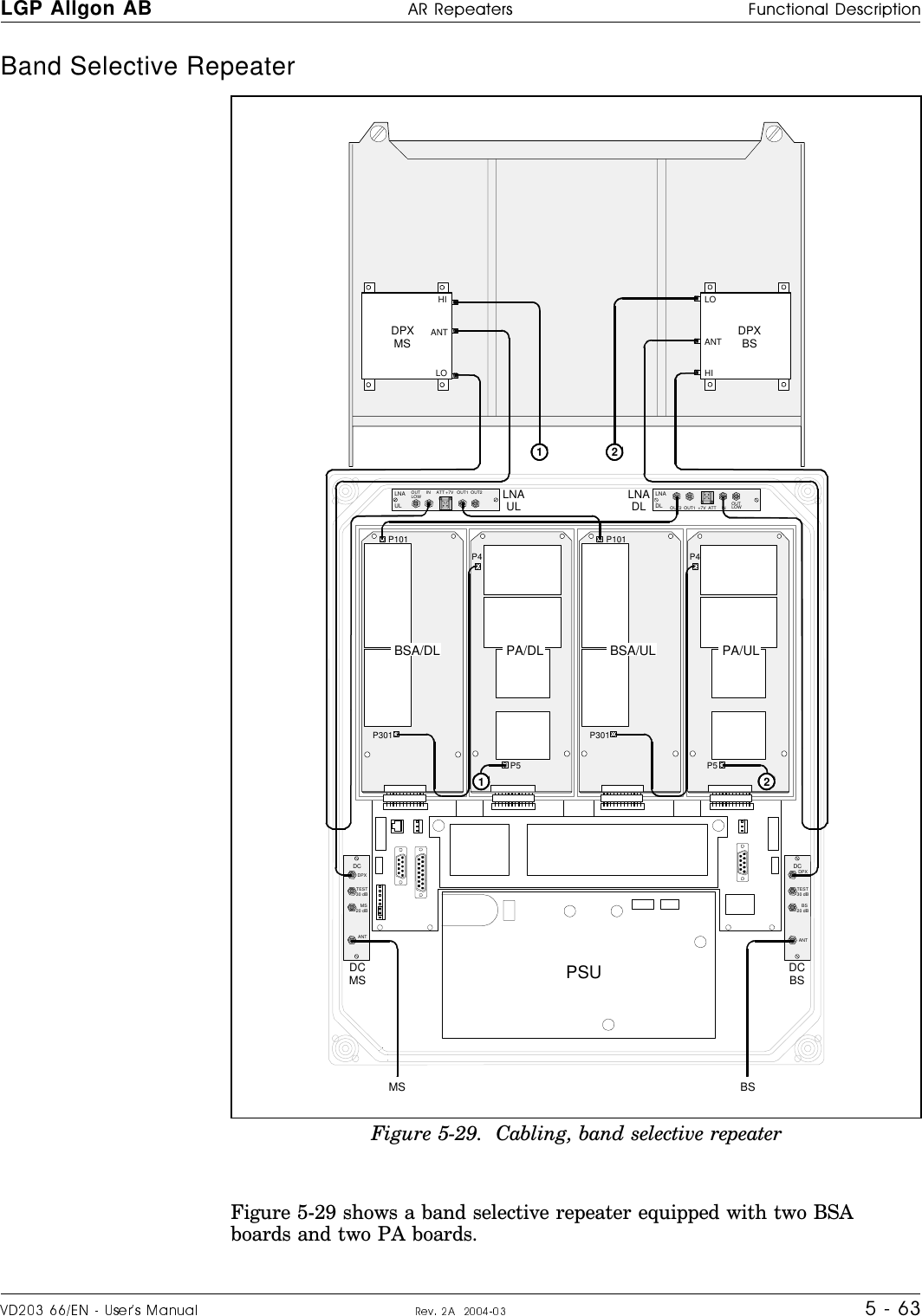
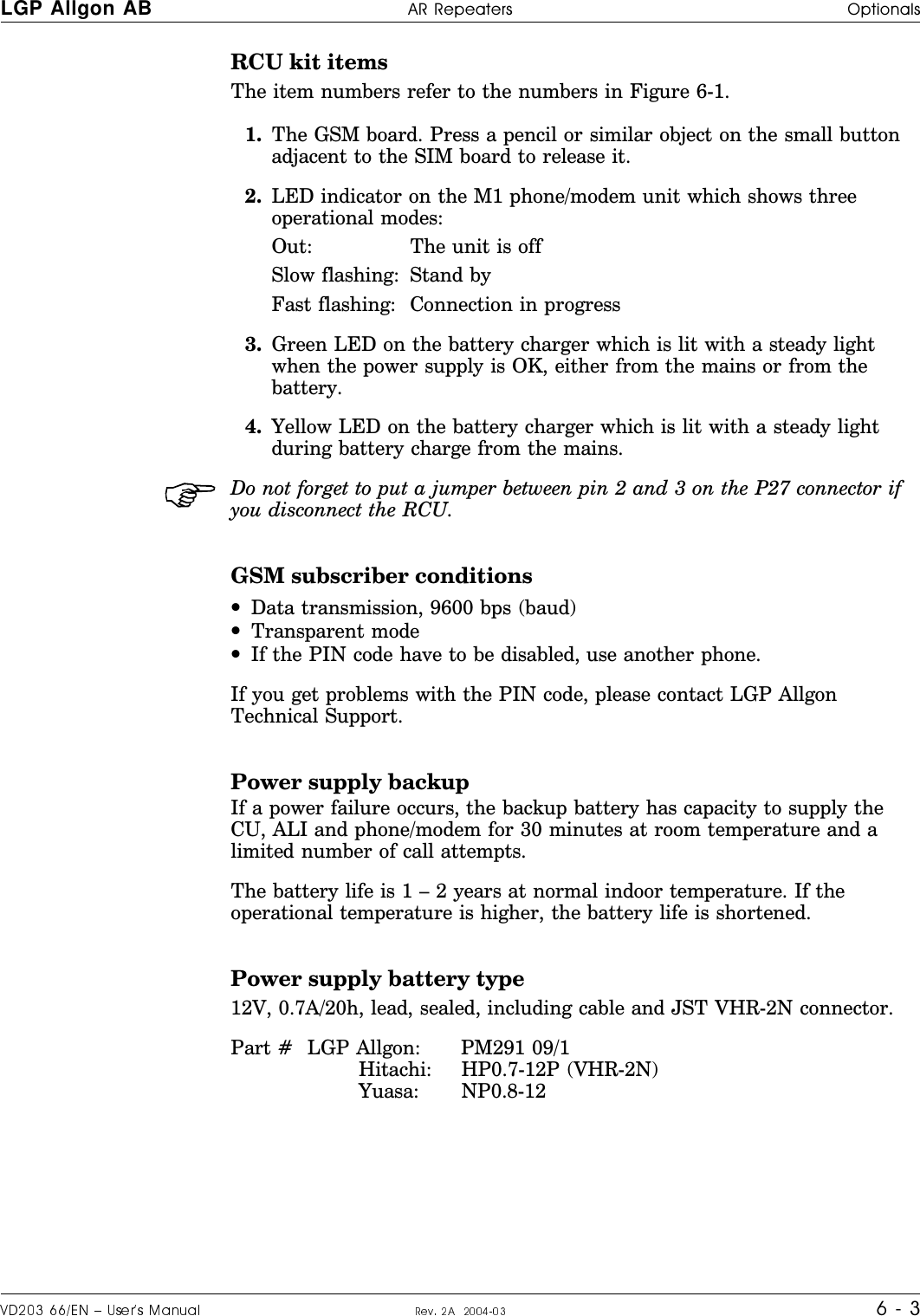
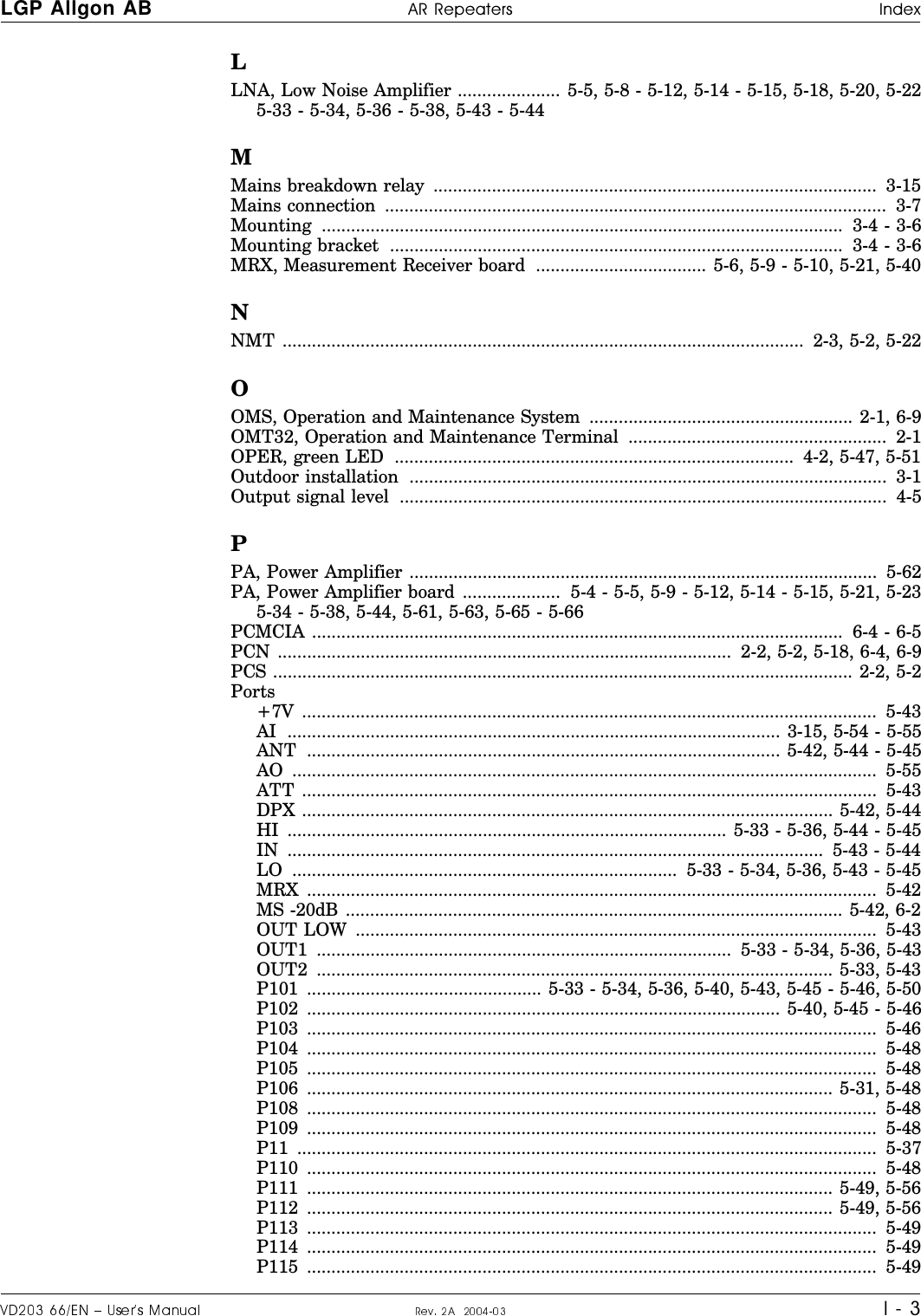
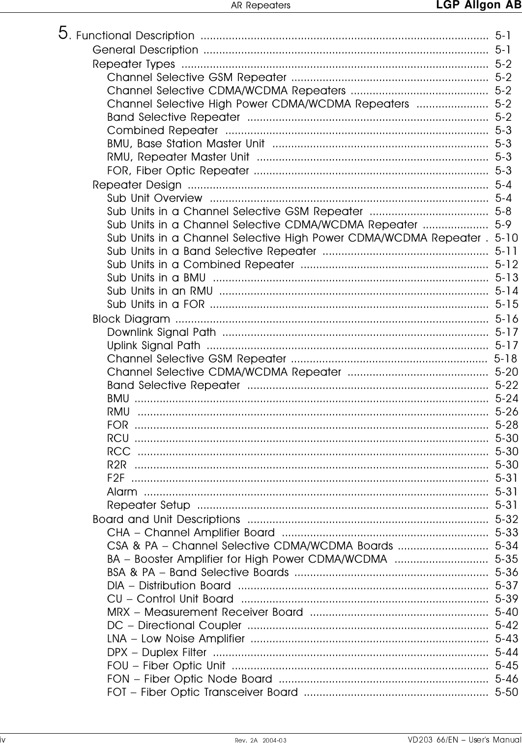
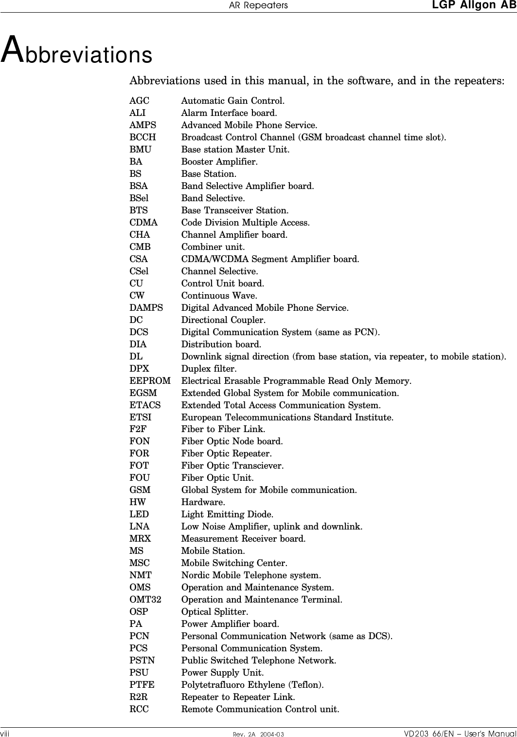
![Safety %66ITIEXIVW LGP Allgon1 - 4Radiation ExposureA29AY\VN2OKV^R9\QKXSdK^SYXKXN3-83<:3X^O\XK^SYXKV-YWWS]]SYXYX8YX3YXS]SXQ<KNSK^SYX:\Y^OM^SYXRK`ONO^O\WSXON\OMYWWOXNK^SYX]PY\\KNSK^SYXObZY]_\O3-83<:\OMYWWOXN]XY^^YObMOON^ROPYVVYaSXQ\KNSK^SYXZYaO\PY\Z_LVSMObZY]_\O$0\O[_OXMc <KNSK^SYXZYaO\#72d AW"72d #AW72d AW0Y\KX^OXXK]VK\QO\^RKXMW^ROWKbSW_W\KNSK^SYXZYaO\MKXLOMKVM_VK^ONLc_]SXQ^ROPYVVYaSXQPY\W_VK$aRO\O= '<KNSK^SYXZYaO\SXAW: '9_^Z_^ZYaO\SXA\ '.S]^KXMOLO^aOOXKX^OXXKKXNR_WKXSXWO^O\>Y^KMUVO^ROaY\]^MK]O]_MMO]]P_VVc^ROMKVM_VK^SYXNYO]XY^MYX]SNO\]c]^OWZYaO\\ON_MSXQKM^SYX]]_MRK]ZYaO\MYX^\YVKXN.>B0SQ_\O ]RYa]^RO]KPO^cNS]^KXMO^YKXKX^OXXKN_O^Y^RO<0\KNSK^SYX>RONS]^KXMOS]NOZOXNSXQYX^ROKX^OXXKY_^Z_^ZYaO\KXNP\O[_OXMcaRSMRS]SVV_]^\K^ONaS^R^aYQ\KZR]SX^ROPSQ_\O9XOYP^ROQ\KZR]KZZVSO]^YAW #72dKXN^ROY^RO\^Y#AW "72dY\AW 72d>RO]KPO^cNS]^KXMO\KXQOSX0SQ_\O S]^Y WO^O\^RK^MY`O\]KXKX^OXXKZYaO\\KXQOYPN,W^YN,WA^YARadiation Safety Distances>RS]]OM^SYXSVV_]^\K^O]^RO]KPO^cNS]^KXMO]^Y^ROKX^OXXK]PY\]YWO^cZSMKV\OZOK^O\MYXPSQ_\K^SYX]9_^NYY\1=7#72d>RO]KPO^cNS]^KXMOMKXLO\OKN^Y! WO^O\SX0SQ_\O K]^ROWKbSW_W\KNSK^SYXZYaO\S]AWPY\#72dSP4πr2××--------------------=<OZOK^O\Y_^Z_^ZYaO\ N,W0OONO\VY]] xN,+X^OXXKQKSX !N,S/3<: N,W](https://usermanual.wiki/Powerwave-Technologies/AR4240.User-Manual-part-1/User-Guide-453031-Page-16.png)
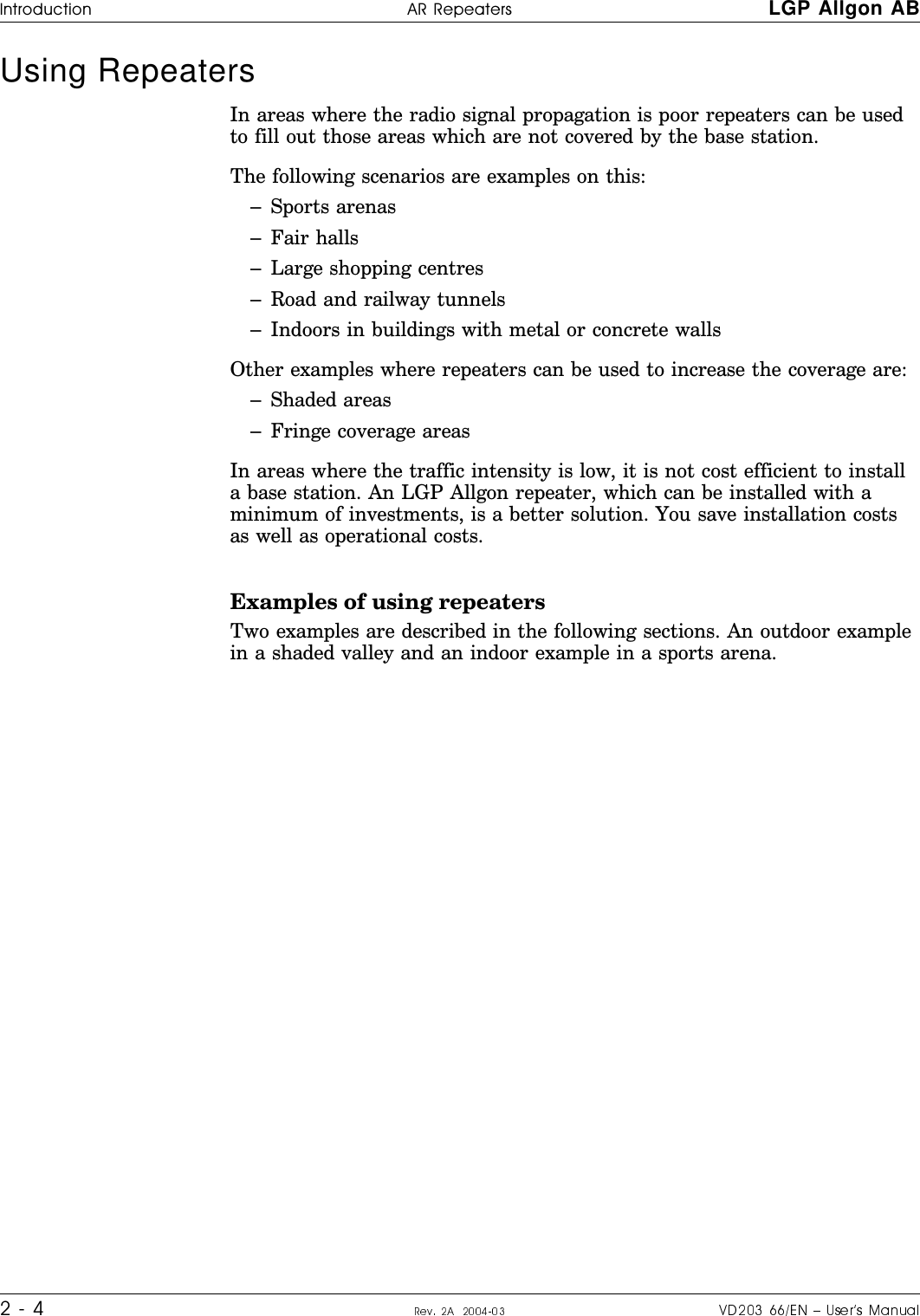
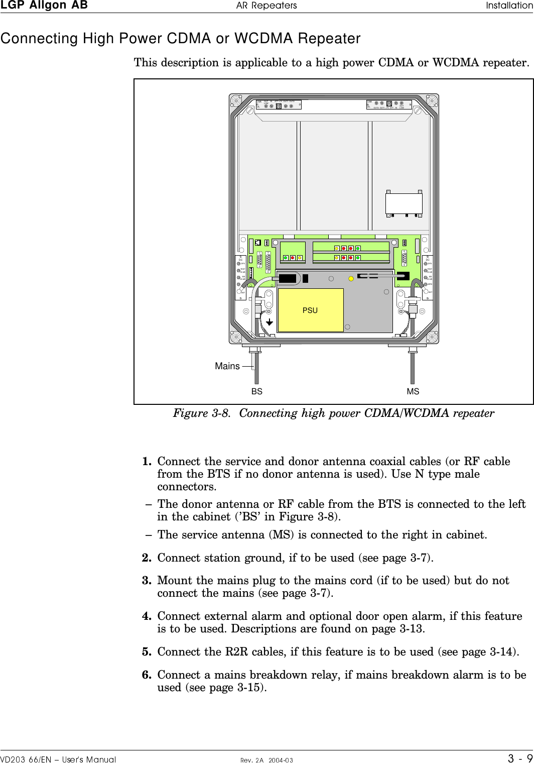
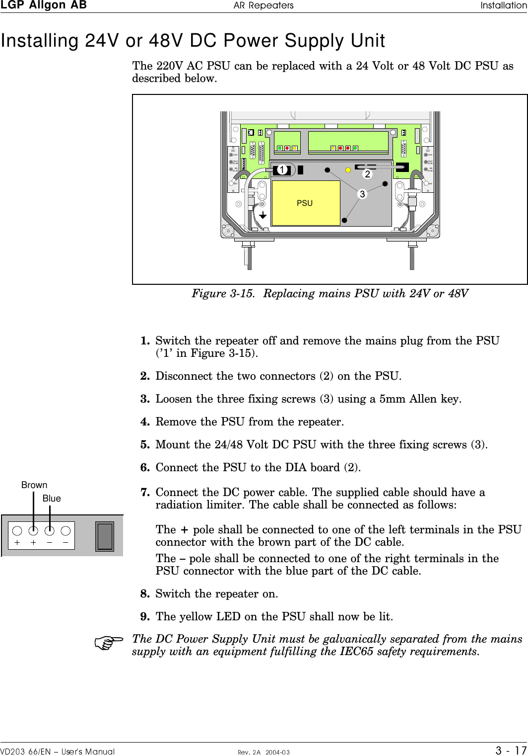
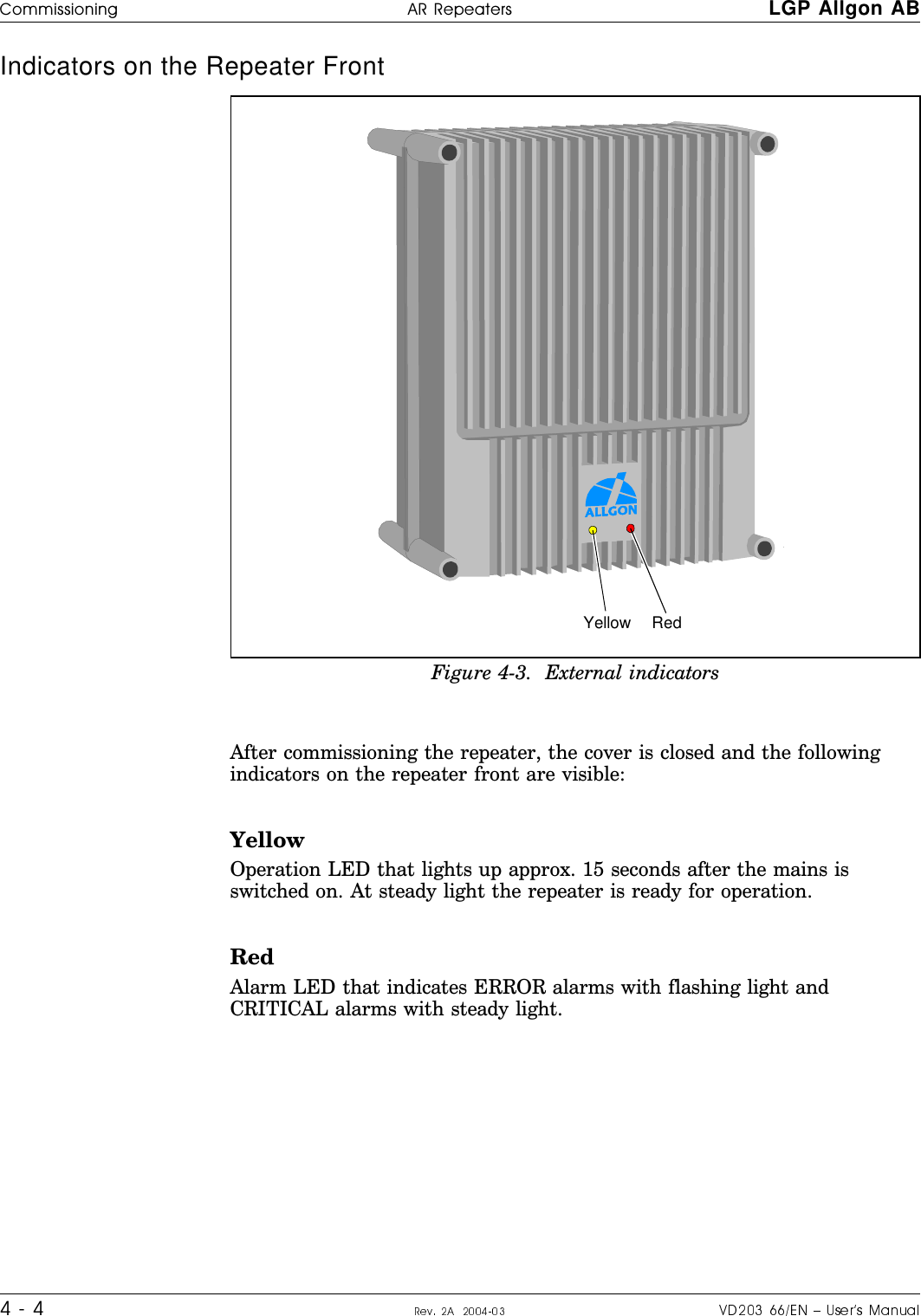
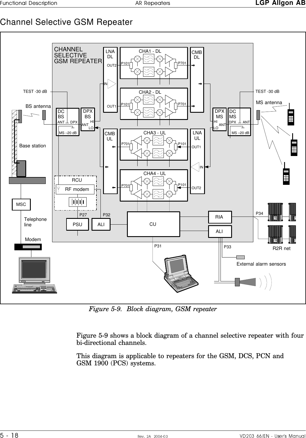
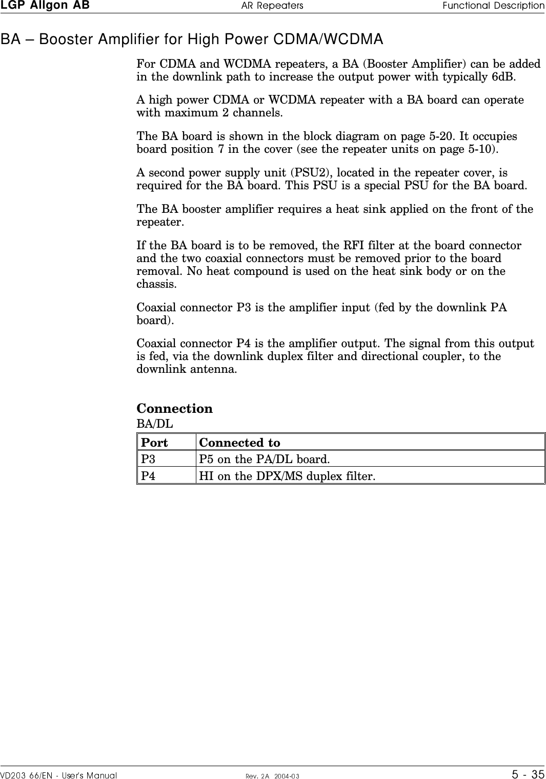
![LGP Allgon %66ITIEXIVW Safety1 - 50SQ_\O=KPO^cNS]^KXMO^YKM^S`OKX^OXXK3XNYY\1=7#72d>RO]KPO^cNS]^KXMOMKXLO\OKN^Y WO^O\PY\AW#72d9_^NYY\?7>==^KXNK\N2SQR:YaO\>RO]KPO^cNS]^KXMOMKXLO\OKN^Y# WO^O\PY\AW72d3XNYY\?7>=>RO]KPO^cNS]^KXMOMKXLO\OKN^Y WO^O\PY\AW72d101520253035400 0.1 0.2 0.3 0.4 0.5 0.6 0.7 0.8 0.9 1.045501.1 1.2 1.3 1.40.010.030.10.31.03.210.031.6100 4.5W/m2 (900MHz) 9W/m2 (1800MHz) 10W/m2 (2100MHz)Safety distance to antenna in meterAntenna output power in dBmAntenna output power in W<OZOK^O\Y_^Z_^ZYaO\ N,W0OONO\VY]] xN,+X^OXXKQKSX N,S/3<: "N,W<OZOK^O\Y_^Z_^ZYaO\ "N,W0OONO\VY]] xN,+X^OXXKQKSX !N,S/3<: N,W<OZOK^O\Y_^Z_^ZYaO\ N,W0OONO\VY]] xN,+X^OXXKQKSX N,S/3<: N,W](https://usermanual.wiki/Powerwave-Technologies/AR4240.User-Manual-part-1/User-Guide-453031-Page-17.png)
![Safety %66ITIEXIVW LGP Allgon1 - 6Static Electricity =^K^SMOVOM^\SMS^cWOKX]XY\S]UYPZO\]YXKVSXT_\cL_^S^MKX]O`O\OVcNKWKQOO]]OX^SKVZK\^]YP^ROO[_SZWOX^SPXY^RKXNVONMK\OP_VVc:K\^]YX^ROZ\SX^ONMS\M_S^LYK\N]K]aOVVK]Y^RO\ZK\^]SX^ROO[_SZWOX^K\O]OX]S^S`O^YOVOM^\Y]^K^SMNS]MRK\QO8O`O\^Y_MR^ROZ\SX^ONMS\M_S^LYK\N]Y\_XSX]_VK^ONMYXN_M^Y\]_\PKMO]_XVO]]KL]YV_^OVcXOMO]]K\c3PcY_W_]^RKXNVO^ROZ\SX^ONMS\M_S^LYK\N]Y\_XSX]_VK^ONMYXN_M^Y\]_\PKMO]_]O/=.Z\Y^OM^S`OO[_SZWOX^Y\PS\]^^Y_MR^ROMRK]]S]aS^RcY_\RKXNKXN^ROXNYXY^WY`OcY_\POO^YX^ROPVYY\8O`O\VO^cY_\MVY^RO]^Y_MRZ\SX^ONMS\M_S^LYK\N]Y\_XSX]_VK^ONMYXN_M^Y\]_\PKMO]+VaKc]]^Y\OZ\SX^ONMS\M_S^LYK\N]SX/=.]KPOLKQ]](https://usermanual.wiki/Powerwave-Technologies/AR4240.User-Manual-part-1/User-Guide-453031-Page-18.png)