Powerwave Technologies DPA4040G PCS Dual Amplifier Booster/Combiner User Manual DPA 4040G Rev 3
Powerwave Technologies, Inc. PCS Dual Amplifier Booster/Combiner DPA 4040G Rev 3
Contents
- 1. Users Manual
- 2. Users Manual Revised
Users Manual Revised

1590 Buckeye Drive
Milpitas, CA 95035
USER MANUAL
PCS GSM and EDGE Dual Power Amplifier
REMEC Model DPA-4040G
DPA-4040G User Manual Rev 3 Page 1 of 1
DPA-4040G User Manual
REMEC’s PCS GSM-EDGE Dual Power Amplifier Model DPA-4040G product consists of two
power amplifiers and a power combiner integrated into one compact housing capable of
amplifying and / or combining one or two PCS 1900 GSM or EDGE modulated RF carriers.
GSM Modulation
For GSM modulation, two supplied user jumper cables allow the user to combine the 2
independent and isolated RF radio carriers into one common output port via the integrated
power combiner. This option reduces the available output power for each RF carrier to 46 dBm
per carrier, or a composite 2- carrier power of 49 dBm. This mode of operation is noted as
Combined Output Mode.
For GSM modulation, the user has the option of removing the jumper cables and connecting
directly to the two independent isolated output connectors of the Dual Power Amplifier. In this
configuration, the output power for each output port is 49.5 dBm separately. This mode of
operation is noted as Isolated Output Mode
EDGE Modulation
For EDGE modulation, two supplied user jumper cables allow the user to combine the 2
independent and isolated RF radio carriers into one common output port via the integrated
power combiner. This option reduces the available output power for each RF carrier to 43 dBm
per carrier, or a composite 2- carrier power of 46 dBm. This mode of operation is noted as
Combined Output Mode.
For EDGE modulation, the user has the option of removing the jumper cables and connecting
directly to the two independent isolated output connectors of the Dual Power Amplifier. In this
configuration, the output power for each output port is 46.5 dBm separately. This mode of
operation is noted as Isolated Output Mode
The DPA-4040G has factory configurable gain only, so input power adjustments must be made
by the user in order to adjust the output power.
This product has integrated DC power-conditioning circuits, monitoring circuits, control circuits,
digital interface circuits and fans. The available monitoring, control circuitry, and digital interface
circuits can be factory configured to meet customer needs of capability and cost flexibility.
The DPA-4040G is a piece of a larger product solution that allows for up to 6 DPAs to be placed
in a common shelf side by side in a 19 inch Rack. The larger product solution consists of an AC
to DC power rectifier and a cable kit to interface input signal, output signal, AC and DC power to
OEM radio equipment. The larger product solution has an optional Amplifier Monitoring Module

1590 Buckeye Drive
Milpitas, CA 95035
USER MANUAL
PCS GSM and EDGE Dual Power Amplifier
REMEC Model DPA-4040G
DPA-4040G User Manual Rev 3 Page 2 of 2
(AMM) that can interface to OEM base station alarms or local monitoring by means of a
Graphical User Interface (GUI). The entire larger product solution is space efficient, consuming
only 6RU of height in a 19-inch rack.
The following instructions should be followed when installing the unit for service:
1. Installation Instructions
1.1 Apply a 28VDC input voltage to the DC Input connector of the DPA-4040G
1.2 Ensure that the DC Source is capable of delivering up to 19 Amps at 28VDC.
1.3 Apply either an Edge or GSM modulated signal to each RF input port of the DPA-4040G.
1.4 Measure the RF output port to ensure the proper output power is present.
1.5 For GSM Modulation, adjust the input power level to ensure the output power level is in
compliance with the values indicated in Table 1 or Table 2 depending upon the mode of
operation (Combined or Isolated).
1.6 For EDGE Modulation, adjust the input power level to ensure the output power level is in
compliance with the values indicated in Table 3 or Table 4 depending upon the mode of
operation (Combined or Isolated).
1.7 To comply with the FCC limits at the second harmonic, 15 dB minimum rejection must be
provided between the DPA and free space. Any or all of the following system elements
can be utilized to provide the required rejection:
1.7.1 A transmit filter
1.7.2 A transmit duplexer
1.7.3 An antenna feed with loss
1.7.4 Antenna pattern attenuation
1590 Buckeye Drive
Milpitas, CA 95035
USER MANUAL
PCS GSM and EDGE Dual Power Amplifier
REMEC Model DPA-4040G
DPA-4040G User Manual Rev 3 Page 3 of 3
Note:
The user must adjust the RF input power to the Booster Amplifier such that the RF output power
level does not exceed the FCC certified power levels. The FCC certified power level is
determined by the RF output spectral emissions to be compliant with the FCC spurious
emissions limit of -13 dBm outside of the assigned frequency block. Near the block edges, the
EDGE and GMSK signal is such that the output power level must be further reduced so that the
-13 dBm spurious level is not exceeded. The other alternative that has been used with this
amplifier is to adjust the channel center frequency until the amplifier is in compliance at the
block edge.
These levels must not be exceeded for FCC compliance.
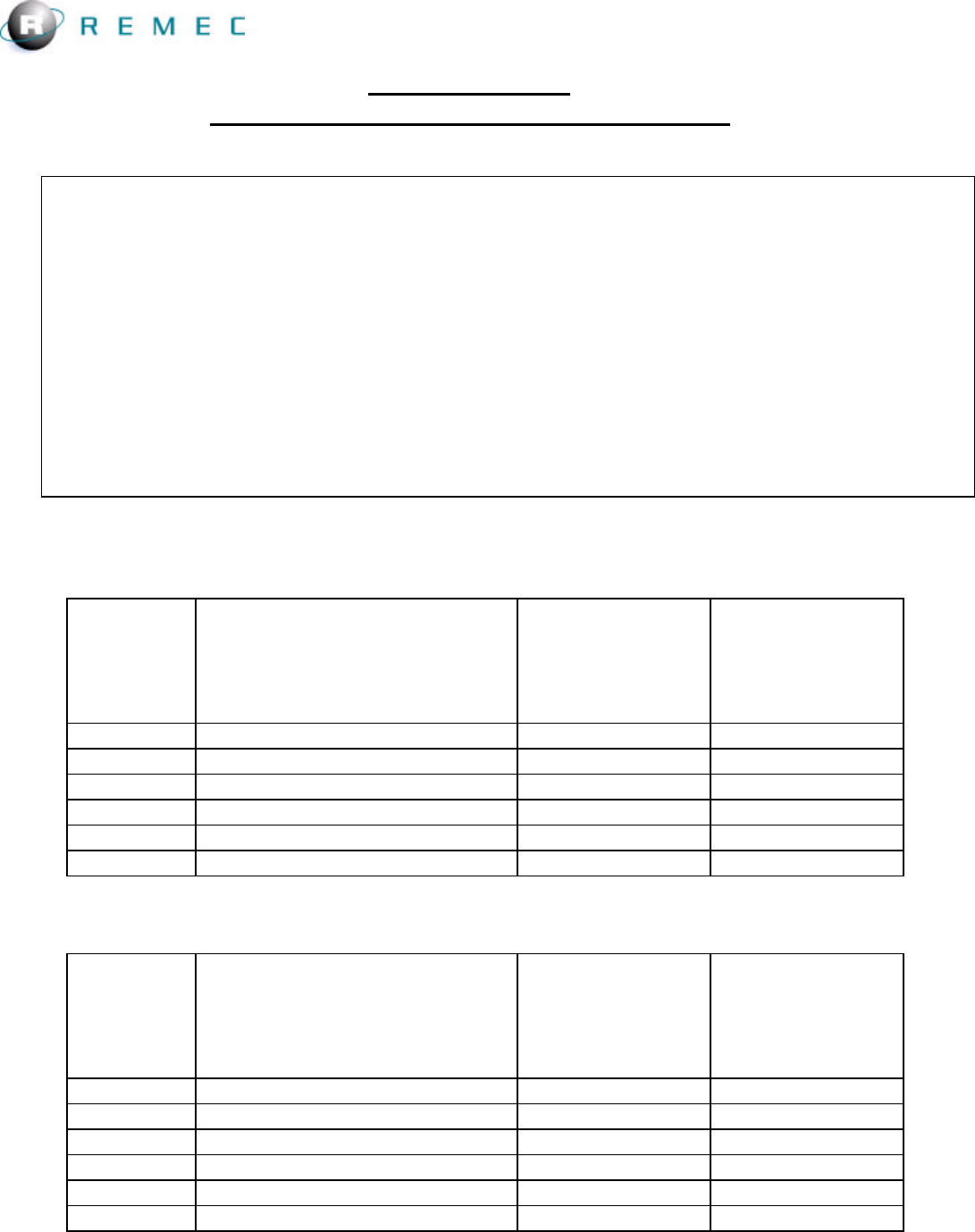
2. Table 1: GSM Maximum Combined Mode Output Power per Carrier
Block Channel Center Frequency
(MHz)
Maximum RF
Output Power
per Carrier
(dBm)
Combined Port
Maximum RF
Output Power
per Carrier
(W)
Combined Port
A 1930.4 - 1944.6 46 39.8
D 1945.4 - 1949.6 46 39.8
B 1950.4 - 1964.6 46 39.8
E 1965.4 - 1969.6 46 39.8
F 1970.4 - 1974.6 46 39.8
C 1975.4 - 1989.6 46 39.8
3. Table 2: GSM Maximum Combined Mode Output Power per Carrier
Block Channel Center Frequency
(MHz)
Maximum RF
Output Power
per Carrier
(dBm)
Combined Port
Maximum RF
Output Power
per Carrier
(W)
Combined Port
A 1930.4 - 1944.6 49.5 89.1
D 1945.4 - 1949.6 49.5 89.1
B 1950.4 - 1964.6 49.5 89.1
E 1965.4 - 1969.6 49.5 89.1
F 1970.4 - 1974.6 49.5 89.1
C 1975.4 - 1989.6 49.5 89.1
1590 Buckeye Drive
Milpitas, CA 95035
USER MANUAL
PCS GSM and EDGE Dual Power Amplifier
REMEC Model DPA-4040G
DPA-4040G User Manual Rev 3 Page 4 of 4
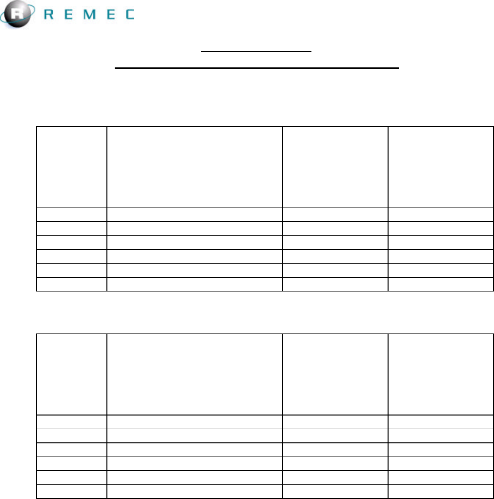
4. Table 3: EDGE Maximum Combined Mode Output Power per Carrier
Block Channel Center Frequency
(MHz)
Maximum RF
Output Power
per Carrier
(dBm)
Each Isolated
Port
Maximum RF
Output Power
per Carrier
(W)
Each Isolated
Port
A 1930.4 - 1944.6 43.0 20
D 1945.4 - 1949.6 43.0 20
B 1950.4 - 1964.6 43.0 20
E 1965.4 - 1969.6 43.0 20
F 1970.4 - 1974.6 43.0 20
C 1975.4 - 1989.6 43.0 20
5. Table 4: EDGE Maximum Isolated Mode Output Power Per Carrier
Block Channel Center Frequency
(MHz)
Maximum RF
Output Power
per Carrier
(dBm)
Each Isolated
Port
Maximum RF
Output Power
per Carrier
(W)
Each Isolated
Port
A 1930.4 - 1944.6 46.5 44.7
D 1945.4 - 1949.6 46.5 44.7
B 1950.4 - 1964.6 46.5 44.7
E 1965.4 - 1969.6 46.5 44.7
F 1970.4 - 1974.6 46.5 44.7
C 1975.4 - 1989.6 46.5 44.7
6. Tune-Up Procedure
There are no user tunable components in the design so no Tune-up procedure is required.
7. FCC Part 24 compliance
Changes or Modifications, not expressly approved by the manufacturer, could void the user's
authority to operate the equipment.
FCC rules for RF exposure require that the antenna connected to this DPA-4040G equipment is
fixed on an outdoor structure with a minimum separation distance of 2 meters between it and
any person.