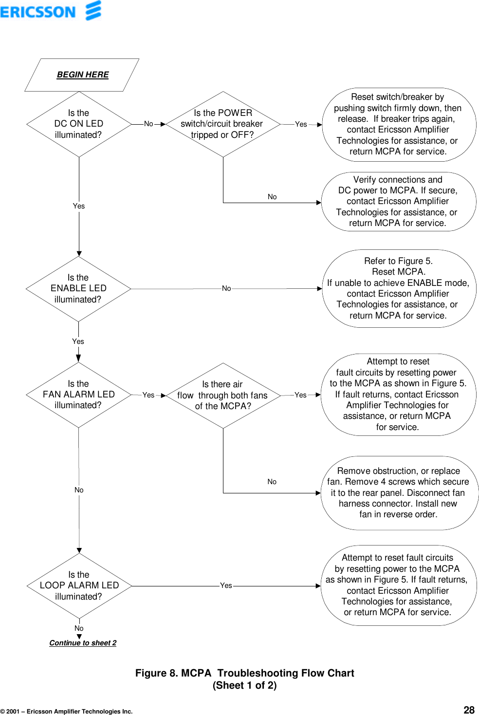
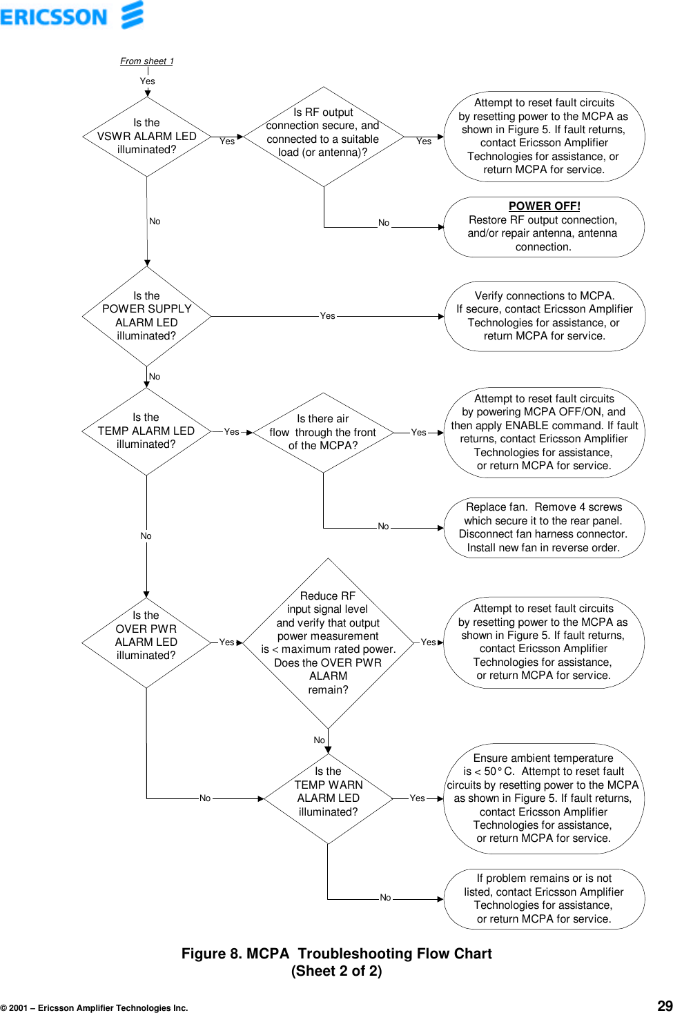
Powerwave Technologies KRB1011108 Multi Carrier Power Amplifier User Manual G8 MCPA Manual R1

Powerwave Technologies, Inc. Multi Carrier Power Amplifier G8 MCPA Manual R1

Contents

User Manual

ERICSSON AMPLIFIER TECHNOLOGIES INC.49 Wireless BoulevardHauppauge,  New York 11788(631) 357-8200MULTI-CARRIERPOWER AMPLIFIERMCPAProduct Number 1/KRB 101 1108INSTALLATION, OPERATION ANDMAINTENANCE INSTRUCTIONSEricsson Amplifier Technologies Inc.Technical Publication MCPARevision APREPAREDMay 23, 2001NOTICEPROPRIETARY AND PRIVATEThe information contained in this document is the property of EricssonAmplifier Technologies Inc., (Company) and shall be kept in strictconfidence. Except with the written permission of the Company, suchinformation shall not be published, or disclosed to others, or used formanufacture or sale or for any other purpose. This document shall not beduplicated in whole or in part. Any recipient so agrees by acceptance of thisdocument.
© 2001 – Ericsson Amplifier Technologies Inc. iThe following symbols are used throughout this technical manual:WARNINGTHIS SYMBOL INDICATES IMPORTANT INFORMATION THAT ISEMPHASIZED TO ALERT THE READER TO THE POTENTIAL RISK OFPERSONAL INJURY TO THE OPERATOR OR OTHER PERSONNEL.CAUTIONThis symbol indicates important information that is emphasized to alert   the reader to the potential risk of damage to the amplifier.NOTEThis symbol indicates information that is highlighted signifying anoperation or procedural step requiring additional emphasis.Ericsson Amplifier Technologies Incorporated provides this technical manual “as is”without warranty of any kind, either expressed or implied.  Ericsson AmplifierTechnologies may make improvements or changes to the product and/or manual at anytime without notice.Every effort has been made to ensure the accuracy and completeness of this technicalmanual, however, it may contain technical inaccuracies or typographical errors.Changes are made periodically to the information contained herein. These changes willbe incorporated into new editions of this technical manual.Ericsson Amplifier Technologies is interested in receiving comments from the users of thismanual in order to improve its usefulness.  All comments should be directed via regularmail to the address listed on the title page of this document.  Ericsson AmplifierTechnologies may use or distribute any of the information supplied in any way it believesappropriate, without incurring any obligations.All specifications are subject to change without notice.WARNINGTHE USE OF AN EARTH GROUND IS REQUIRED TOENSURE SAFETY.IF THE EQUIPMENT APPEARS TO BE DAMAGED IN ANYWAY, REMOVE ALL POWER TO THE UNIT, AND HAVE ITSERVICED AS SOON AS POSSIBLE.
© 2001 – Ericsson Amplifier Technologies Inc. ivRETURN FOR REPAIRFIELD OPERATION SUMMARY SHEETPlease make a copy of this sheet, and complete the following questionnaire.  If necessary, attachadditional sheets.  This information will assist in expediting repairs to the equipment, and is used for faulttrend analyses and ongoing product improvement.FIELD TECH NAME:_______________________________  DATE: _____________________________EQUIPMENT LOCATION (CELL SITE NUMBER): _______________________________________________________________________________________________________________________________MODEL NUMBER: ____________________________________________________________________SERIAL NUMBER: ____________________________________________________________________FREQUENCY OF OPERATION:  A:__________________________  B:  _________________________CARRIER POWER:____________________________________________________________________MAXIMUM NUMBER OF CARRIERS: _____________________________________________________LED INDICATOR STATUS:LED DESCRIPTION LED ONCheck þLED OFFCheck þDC ON: o oENABLE: o oFAN ALARM: o oLOOP ALARM: o oVSWR ALARM: o oPOWER SUPPLYALARM:o oTEMPERATURE ALARM: o oOVER POWER ALARM: o oUNIT SURFACE TEMPERATURE: _______________________________________________________POWER SUPPLY MODEL OR CAPABILITY: ___________________________________________________________________________________________________________________________________OTHER DETAILS OF PROBLEM REPORTED:______________________________________________________________________________________________________________________________________________________________________________________________________________________
© 2001 – Ericsson Amplifier Technologies Inc. vTable of Contents1. GENERAL DESCRIPTION.....................................................................................11.1 Introduction .............................................................................................................................11.2 Related Publications ...............................................................................................................11.3 General Description.................................................................................................................11.4 Equipment Functional and Physical Specifications..............................................................21.5 Mechanical Description...........................................................................................................32. INSTALLATION .....................................................................................................42.1 Introduction .............................................................................................................................42.2 Electrical Service Recommendations.....................................................................................42.3 Receiving, Unpacking and Inspection....................................................................................42.4 Repackaging for Shipment .....................................................................................................42.5 Environmental Limitations......................................................................................................52.6 Installation ...............................................................................................................................52.6.1 Recommended Tools..........................................................................................................52.6.2 Blind Mate Configuration Mounting .....................................................................................52.7 Cable Interconnections ...........................................................................................................72.8 Verify Connections..................................................................................................................82.9 Verify DC Supply Voltage........................................................................................................83. OPERATING INSTRUCTIONS...............................................................................93.1 Safety Precautions ..................................................................................................................93.2 Controls and Indicators ........................................................................................................103.2.1 Local Controls and Indicators............................................................................................103.2.2 MCPA Power ON/OFF Sequence Summary .....................................................................133.2.3 Remote Control/Status Interface.......................................................................................153.3 Initial Turn On Procedure......................................................................................................153.4 Normal Operation ..................................................................................................................163.5 Shut Down Procedure ...........................................................................................................164. PRINCIPLES OF OPERATION ............................................................................174.1 Introduction ...........................................................................................................................174.2 RF Input Signal......................................................................................................................174.3 RF Output Load .....................................................................................................................174.4 System Functional Description ............................................................................................174.4.1 Main Amplifier ..................................................................................................................194.4.2 Error Amplifier ..................................................................................................................194.4.3 Amplitude and Phase Adjustment .....................................................................................194.4.4 Amplifier Module Cooling..................................................................................................204.5 Power Distribution.................................................................................................................204.6 Intermodulation Distortion Performance .............................................................................204.6.1 Intermodulation Distortion.................................................................................................204.7 Description of Operating Modes...........................................................................................204.7.1 Default mode ...................................................................................................................20
© 2001 – Ericsson Amplifier Technologies Inc. vi4.7.2 Standby Mode: ................................................................................................................214.7.3 DC On Mode ....................................................................................................................214.7.4 Enable Mode....................................................................................................................214.7.5 Shutdown Mode ..............................................................................................................214.7.6 ALC Mode ........................................................................................................................214.7.7 Locking Mode..................................................................................................................224.8 Description of Alarm Conditions ..........................................................................................224.8.1 LOOP Alarm.....................................................................................................................224.8.2 VSWR Alarm....................................................................................................................224.8.3 TEMP/WARN Alarm .........................................................................................................224.8.4 PWR SPLY Alarm ............................................................................................................234.8.5 FAN Alarm........................................................................................................................234.8.6 OVER PWR Alarm ...........................................................................................................235. MAINTENANCE ...................................................................................................255.1 Introduction ...........................................................................................................................255.2 Periodic Maintenance............................................................................................................255.2.1 Cleaning Air Inlets/Outlets ................................................................................................265.2.2 Test Equipment Required .................................................................................................265.2.3 Performance Tests ...........................................................................................................265.3 Troubleshooting Procedures................................................................................................275.4 Fan Assembly Replacement Procedure ...............................................................................27List of FiguresFigure 1. Ericsson Amplifier Technologies Inc. Multi-Carrier Power Amplifier.....................2Figure 2. Outline/Installation Drawing, Ericsson Amplifier Technologies MCPA .................6Figure 3. MCPA Local Controls and Indicators.....................................................................11Figure 4. MCPA Power ON/OFF Sequence............................................................................14Figure 5. Block Diagram, MCPA Power Amplifier.................................................................24Figure 6. MCPA Troubleshooting Flow Chart  ......................................................................28List of TablesTable 1. Performance Characteristics, MCPA Power Amplifier.............................................3Table 2. J1 – Blind Mate 24W7 D Sub-miniature Connector..................................................7Table 3. MCPA Local Controls and Indicators......................................................................12Table 4. Periodic Maintenance Tasks....................................................................................25Table 5. Test Equipment Required ........................................................................................26
© 2001 – Ericsson Amplifier Technologies Inc. 11. GENERAL DESCRIPTION1.1 IntroductionThis manual provides information for the installation, operation and maintenance ofEricsson Amplifier Technologies MCPA multi-carrier power amplifier.The manual is organized in 6 sections as follows:• Section 1. General Description• Section 2. Installation• Section 3. Operating Instructions• Section 4. Principles of Operation• Section 5. Maintenance• Section 6. Photographs1.2 Related PublicationsTMHPC8689-400 -  ERICSSON AMPLIFIER TECHNOLOGIESINSTALLATION, OPERATION ANDMAINTENANCE INSTRUCTIONS FORSUBRACK ASSEMBLY1.3 General DescriptionThe MCPA (Figure 1) is a microprocessor controlled, linear multi-carrier poweramplifier (MCPA), which operates over the frequency range of 869 to 894 MHz with arated output power of 120 watts total (average).  At rated output, the amplifier providesintermodulation products of better than 63 dBc.  The design of the MCPA is entirelysolid state, providing trouble free operation and a minimum of maintenance. The MCPAincludes a high-speed I/O port to receive commands from the host controller.  TheMCPA is equipped with microprocessor controlled status monitoring and controlcircuitry which monitors key MCPA operating conditions and provides remote statusoutput via the rear panel I/O connector.  Local operating status is provided via frontpanel LED indicators.  The MCPA is powered by an external (customer supplied) 26-28VDC power supply.
© 2001 – Ericsson Amplifier Technologies Inc. 2Figure 1. Ericsson Amplifier Technologies Inc.MCPA Power Amplifier1.4 Equipment Functional and Physical SpecificationsTable 1 lists the functional and physical specifications of the MCPA power amplifier.
© 2001 – Ericsson Amplifier Technologies Inc. 3Table 1. Performance CharacteristicsMCPA Power AmplifierPERFORMANCE CHARACTERISTICSParameter SpecificationFrequency 869 - 894 MHzRF Output Power 120 Watts AverageIntermodulation Distortion -3 dBc minimumwhen measured with 50 random phase sets.Gain 69.5±0.25 dBModulation Format AnyInput Return Loss 14 dBr MinimumLoad Stability VSWR unconditional, all phasesCurrent Consumption 50 amperes nominal @ 27 VDCDC Input Fully operational from 26 to 28 VDCOperating Temperature 5° to 40° COperating Humidity 20% to 80% RH, non-condensingStorage Humidity 20% to 95% RH, non-condensingDimensions 17.88” H x 5.12” D x 16.5” D45.4 cm H x 13 cm W x 41.9 cm D(Optional Configuration Available)RF, DC, and I/O interface (Blind mate): 24W7 Sub-miniature connector, OSPLED Status Monitoring Loop Alarm, VSWR Alarm, TemperatureAlarm, Power Supply Alarm, Fan Alarm,Over Power Alarm, and DC On1.5 Mechanical DescriptionThe MCPA is contained in a chassis that can be mounted in a subrack enclosure.  Acentral heatsink is permanently mounted as part of the assembly  (casting/housing).Cooling is provided by 2 integral rear mounted fans that are easily replaced without theneed for chassis disassembly, or removal of power to the amplifier.  Airflow through theMCPA is from front through the rear of the unit.
© 2001 – Ericsson Amplifier Technologies Inc. 42. INSTALLATION2.1 IntroductionThis section contains receiving, unpacking and installation recommendations for theEricsson Amplifier Technologies MCPA multi-carrier power amplifier.  Carefully readand review all of the information contained in this section before attempting to install oroperate the MCPA.  In addition, read and review the operating instructions contained inSection 3 before operating the equipment.2.2 Electrical Service RecommendationsEricsson Amplifier Technologies strongly recommends the use of AC line conditioningand surge suppression devices at the primary AC input to the power source for theMCPA.  All electrical connections should be in accordance with the National ElectricCode, and any applicable state and local codes.  In addition, lightning protection for allsystems is strongly recommended.  The electric service must be well grounded.The amplifier power source should be equipped with a separate circuit breaker,installed in a load center with a separate mains switch or breaker.  This arrangementpermits future service and maintenance of the MCPA without the necessity forremoving power to the entire site.2.3 Receiving, Unpacking and InspectionThe MCPA has been tested and calibrated at the factory prior to shipment.  Noadditional readjustment is required prior to installation.The MCPA is shipped in a single container.  Check the exterior of the shippingcontainer for any visible signs of damage.  If possible, open the container in thepresence of the delivery agent.  Carefully unpack the MCPA and save all packingmaterial for possible reshipment.  After removal from the container, check the MCPA forphysical damage such as scratched panels, damaged connectors, etc. If damage isnoted, immediately file claim with the delivery agent or freight carrier.2.4 Repackaging for ShipmentShould it ever become necessary to re-ship the MCPA for service or repair, thefollowing procedure should be followed.a. Use the original container, if possible.b. Wrap the item in heavy paper or plastic before placing it in the shipping container.c. Use packing material around all sides of the item.d. Use a heavy cardboard box or a wooden container to house the item. Seal thecontainer with heavy-duty tape (Fiberglas) or strap the container with metal bands.e. Mark the container: "FRAGILE - DELICATE INSTRUMENT".
© 2001 – Ericsson Amplifier Technologies Inc. 52.5 Environmental LimitationsThe MCPA is designed to operate in an environment as noted in Table 1 of thismanual. The MCPA must be installed in an area where an adequate and unrestrictedsupply of air is available for cooling. Adequate clearance must be provided to preventobstruction of airflow. Confirm that proper dc power is available for the equipment.2.6 InstallationThe amplifier is produced in a Blind Mate configuration as shown in Figure 2.  TheBlind Mate configuration is designed for mounting in an Ericsson AmplifierTechnologies subrack, and features a single connector on the rear panel for all RF, DCand I/O interface connections.  The following paragraphs provide installation details.2.6.1 Recommended ToolsThe following tools are recommended to assist in the installation of the amplifier.• #1 and #2 Phillips screwdrivers• Slotted screwdrivers, 1/8” and 1/4”• A 5/16” or 3.5mm open-end wrench• A multi-meter with probes2.6.2 Blind Mate Configuration Mountinga. Install an amplifier module into each of the mating slots of the subrack, beginningfrom the left.  Use firm, but not excessive force when installing the amplifiers toensure a good connection is made.b. Hand tighten the retaining screws on the front panels of the amplifier modules.  Donot over tighten.c. Ensure that an unrestricted supply of air is available at the front and rear of theenclosure for cooling.
© 2001 – Ericsson Amplifier Technologies Inc.
© 2001 – Ericsson Amplifier Technologies Inc. 72.7  Cable InterconnectionsThe MCPA is produced in a Blind Mate configuration.  The following paragraphs provideinterconnection details.CAUTIONVERIFY THAT PROPER DC VOLTAGE IS AVAILABLE TO MCPABEFORE CONNECTIONS ARE MADE.  DAMAGE TO THE MCPACAN OCCUR IF IMPROPER VOLTAGES ARE APPLIED.The RF input, DC, and I/O interface is incorporated into a 24W7 Blind Mate “D” sub-miniatureconnector, J1.  Connections are as shown in Table 2.  RF output is via an OSP Blind Mateconnector, J2.Table 2. J1 – Blind mate 24W7 D Sub-miniature ConnectorJ1-Connector Pin Signal Name DescriptionA1 RF In PKZ26A2, A7 No Connection No ConnectionA3, A4 +DC Power InA5, A6 DC Power Return1-6 No Connection No Connection7 RS-232 RXD_PS Data Out 18 RS-232 TXD_PS Data In 19 Signal Ground Ground10 RUN/PGM PS11 RS-232 TXD_IMD Data Out 212 RS-232 RXD_IMD Data In 213 RUN/PGM IMD14 PA ID, GND15-17 No Connection No Connection
© 2001 – Ericsson Amplifier Technologies Inc. 82.8  Verify ConnectionsRecheck all connections.  Make certain that all connections are correct and secure.2.9  Verify DC Supply VoltageMeasure the DC supply voltage that will power the MCPA at the subrack terminals.   The DCsupply voltage must be 27 VDC ±0.5 VDC.  In addition, the power supply circuit breakerrating must be 75 amperes minimum.  Refer to Section 3 for operating instructions. CAUTIONDO NOT OPERATE MCPA WITH A DC SUPPLY VOLTAGEOUTSIDE OF THESE LIMITS.  DAMAGE WILL OCCUR TO THEMCPA FROM IMPROPER SUPPLY APPLICATION.NOTEWhen +27VDC is initially connected and applied to the MCPA,all of the LED’s on the front panel except for the DC On willilluminate momentarily.
© 2001 – Ericsson Amplifier Technologies Inc. 93. OPERATING INSTRUCTIONS3.1  Safety PrecautionsDuring normal MCPA operation, personnel must be cognizant of the intrinsic hazardsrelated to electronic equipment in general, and RF power amplifiers in particular. Thisamplifier subsystem generates high RF power (120 watts) which is dangerous and cancause serious RF burns if contacted. Caution must be exercised when working with thisamplifier. While every practicable safety precaution has been incorporated into thisamplifier, the following rules must be strictly observed:WARNINGKEEP AWAY FROM LIVE CIRCUITSOperating personnel must observe all safety regulationsat all times. Do not make adjustments inside equipmentwith hazardous voltages present. Do not operate theamplifier without proper RF termination.DO NOT SERVICE OR ADJUST ALONEUnder no circumstances should any person reach withinor enter any enclosure for purposes of servicing oradjustment without the immediate presence andassistance of another person capable of rendering aid.Knowledge of first aid for electrical shock and burns isnecessary.PERSONNELOnly trained personnel are to service and adjust theamplifier. Personnel must be trained in the maintenanceof equipment with hazardous RF power, and must befamiliar with this amplifier. In addition, the followingprecautions must be observed during operation.
© 2001 – Ericsson Amplifier Technologies Inc. 10WARNINGMAINTAIN PROPER TERMINATION AT THE OUTPUTPORT OF THE MCPA.  DO NOT REMOVE OR EXCHANGERF CABLES OF THE OUTPUT LOAD CIRCUIT WHILETHE MCPA IS IN OPERATION. DANGEROUS RFVOLTAGE MAY EXIST AT THE FOREMOST TERMINALOF THE INTERRUPTED LOAD CIRCUIT DURINGOPERATION.CAUTIONAll interconnecting cables must be connected prior toapplication of RF power. Although the MCPA isdesigned to withstand all output load conditionsincluding open and short circuit conditions, it isrecommended to connect an appropriate RF load to theoutput port of the MCPA prior to application of RFpower.CAUTIONMaintain proper RF input to the MCPA. Damage to theMCPA may occur if excessive RF input is applied.3.2  Controls and IndicatorsThe MCPA is equipped with local controls and indicators on the front panel, and a rearpanel I/O interface for remote status monitoring and control.  The following paragraphsdetail these features.3.2.1  Local Controls and IndicatorsFigure 3 is the front view of the MCPA. Table 3 describes the local controls andindicators.
© 2001 – Ericsson Amplifier Technologies Inc. 11Figure 3. MCPA Local Controls and IndicatorsENABLE LEDFAN LEDLOOP LEDVSWR LEDPWR SPLY LEDOVER PWR LEDDC ON/OFF SWITCHAND INDICATORTEMP/WARN LEDENABLESWITCH
© 2001 – Ericsson Amplifier Technologies Inc. 12Table 3.MCPA Local Controls and IndicatorsCONTROL/INDICATOR FUNCTIONDC ON - Power Supply switch and integral DC ON green LED indicator, enablesthe external high power +27V power supply circuitry.ENABLE ON - Green LED indicates unit is ENABLED, biased on and the amplifier isready to amplify signals.FAN ALARM - Yellow LED indicating a blocked or non-functioning fan.LOOP ALARM(Steady On)- Steady (not blinking) Red LED indicating internal control loops can nolonger minimize IMD performance.  The sequence of disable andenable commands may be used to reset the loops to their normalconditions.LOOP ALARM –(Blinking On/Off, indicatesLocking Mode)Blinking red LED indicating Locking Mode has been entered.  Thelocking mode is used to indicate when the module is unable tominimize IMD performance and is attempting to adjust loopcoefficients. During this mode, IMD performance may not meetspecified values. The module will attempt to improve performance for1 minute. If unable to improve performance during this period, themodule will indicate a loop alarm and enter the shutdown mode, andwill require power to be reset in order to clear the fault.VSWR ALARM - Red LED indicating load VSWR is greater than 3.0:1. Amplifier willenter shutdown mode, and will require power to be reset in order toclear the fault.POWER SUPPLY ALARM - Red LED indicating a power supply generated voltage is out of range.Amplifier will enter shutdown mode, and will require power to be resetin order to clear the fault.TEMP WARNING/ALARM -Dual color (Yellow/Red) LED. TEMP WARNING: Yellow color indicates approach of excessiveoperating temperature of approximately +80°C as monitored on theheatsink.  Operation of the MCPA can continue uninterrupted duringthis warning condition.TEMP ALARM: Red color indicates excessive operating temperatureof approximately +90°C as monitored on the heatsink.  Operation ofthe MCPA is disabled until the heatsink has cooled to a safe operatingtemperature, at which point, operation will automatically resume.OVERPOWER ALARM - Red LED indicating that the RF output power from the MCPA is greaterthan 2 dB above nominal output power.  Amplifier will enter shutdownmode, and will require power to be reset in order to clear the fault.NOTEActivation of the LOOP ALARM, VSWR ALARM, POWER SUPPLYALARM, TEMP ALARM or OVERPOWER ALARM will cause theAmplifier to enter shutdown mode.  The amplifier will attempt to autorecover up to three times within 24 hours.  If the alarm is still present,the amplifier will continue to shutdown.  The amplifier may also bemanually reset using the front panel button.  Refer to Figure 4, whichdetails the ON/OFF sequence of the MCPA.
© 2001 – Ericsson Amplifier Technologies Inc. 133.2.2  MCPA Power ON/OFF Sequence SummaryFigure 4 is a functional diagram of the MCPA Power ON/OFF sequence.Initially, the MCPA +27 VDC and +15 VDC bias are both off.After depressing the On/Off switch, both the external +27 VDC and +15 VDC bias areon.  Typical current without any RF applied to the MCPA is 18 amps.Depressing the On/Off switch again will turn off the MCPA module completely, as it wasinitially.
© 2001 – Ericsson Amplifier Technologies Inc. 14Figure 4. MCPA Power ON/OFF SequenceInitial state.MCPA is shut down.Minimal current draw.Module bias isapplied.  MCPA isenabled as indicatedby front panelENABLE LED.Current drawapproximately 18amps.OFF OFF OFF DISABLEDDC ON LEDSTATUS ENABLE LEDSTATUSINTERNALPOWER SUPPLYSTATUSMCPASTATUSDC ON/OFFDEPRESSON ON ON ENABLEDDC ON LEDSTATUS ENABLE LEDSTATUSINTERNALPOWER SUPPLYSTATUSMCPASTATUSDC ON/OFFDEPRESSOPERATINGSTATUSOPERATINGSTATUSNOTE:If resetting power to the MCPA does not clear the fault condition, contact Ericsson Amplifier Technologies,or return MCPA for service.
© 2001 – Ericsson Amplifier Technologies Inc. 153.2.3  Remote Control/Status InterfaceThe MCPA is equipped with control inputs and status outputs at the I/O interface.Section 2.7 details the interfaces for the Blind mate configurations and describes thesignals.3.3  Initial Turn On ProcedureThe following procedure is intended to verify operation of the MCPA followinginstallation, repair or replacement.WARNINGEQUIPMENT OPERATORS MUST BE FAMILIAR WITHALL SAFETY PRECAUTIONS OUTLINED AT THEBEGINNING OF THIS SECTION PRIOR TO OPERATINGTHE MCPA. OPERATOR INJURY AND/OR EQUIPMENTDAMAGE WILL RESULT FROM IMPROPER OPERATION.a. Verify that all connections to the MCPA have been properly made in accordance withSection 2 of this manual, and the outline and installation drawing, Figure 2.NOTEWhen +27VDC is initially connected and applied to theamplifier, all of the LED’s on the front panel, except for theDC ON, will illuminate momentarily.  This is a normalcondition.b. With no RF applied to the MCPA, press the POWER ON/OFF switch once.  The DCON LED (part of the ON/OFF switch) will be illuminated, and the fans will be activated.c. Observe that only the following indicators are illuminated on the MCPA front panel:DC ONENABLEd. Apply reduced RF input (-40 dBm) to the MCPA RF IN connector within the 869-894MHz frequency range, and observe that only the DC ON and ENABLE LED indicatorsremain illuminated.
© 2001 – Ericsson Amplifier Technologies Inc. 16CAUTIONMaintain proper RF input level within the 869-894 MHzoperating band. Improper RF input may cause severeMCPA damage.g. Increase input level to between -19 and -15 dBm, and observe that  only thefollowing indicators are illuminated on the MCPA front panel.DC ONENABLE3.4  Normal OperationThe MCPA requires minimum attention during normal operation. Monitoring of thestatus output provides an overall indication of MCPA health.3.5  Shut Down Procedurea. Reduce RF input signal level to minimum (-60 dBm).b. Press the PWR ON/OFF switch once to disable the bias voltage and to disable +27VDC to the internal amplifier module.  The DC ON indicator will be extinguished.WARNINGTHE DC ON/OFF SWITCH DOES NOT CONTROL THEMAIN +27 VDC FEED TO THE MCPA.  IF MAINTENANCEOR SERVICE IS TO BE PERFORMED ON THE MCPA,DEACTIVATE PRIME DC POWER AT ITS SOURCE.
© 2001 – Ericsson Amplifier Technologies Inc. 174. PRINCIPLES OF OPERATION4.1  IntroductionThis section contains a functional description of the multi-carrier power amplifier.  Referto the block diagram of the MCPA, Figure 5, located at the end of this section.4.2  RF Input SignalThe maximum input signal for all carrier frequencies must not exceed the limitsspecified in the electrical specifications.  The input VSWR should be 2:1 maximum (orbetter).4.3  RF Output LoadThe load impedance should be as close as possible to 50 ohms (VSWR of 1.5:1 orless) over the 869-894 MHz operating frequency band to ensure maximum RF powertransfer to the load.4.4  System Functional DescriptionThe MCPA amplifier is a multi-carrier, feed forward power amplifier, which operatesfrom 869 to 894 MHz with a rated output power of 120W total (average).  The amplifieremploys feed forward carrier cancellation circuitry, providing extremely lowintermodulation products, equal to or less than –63 dBc.  The front panel of theamplifier contains the DC ON/OFF switch, and the status LEDs.  The amplifier operatesfrom a 26-28 VDC input power source, and provides a rear panel input/output (I/O)control and status interface to report all faults and alarms.  Relay dry contacts areprovided for the following fault conditions:OVERPWR – Relay dry contact closure provided for remote notification in the eventthat the MCPA output is greater than 2 dB above the nominal operating power level.The MCPA power will need to be reset in order to clear this fault condition.MINORFLT – Relay dry contact closure provided for remote notification in the eventthat the MCPA has encountered a minor fault condition, which has not caused shutdown of the amplifier, but which will require attention as soon as possible in order toensure uninterrupted operation.  A TEMP WARNING or FAN ALARM will result in aMINORFLT condition and remote notification. The MCPA power will need to be reset inorder to clear this fault condition.MAJORFLT – Relay dry contact closure provided for remote notification in the event ofa potentially damaging fault condition, which has resulted in shut down of the MCPA.Activation of the LOOP ALARM, VSWR ALARM, POWER SUPPLY ALARM, TEMP
© 2001 – Ericsson Amplifier Technologies Inc. 18ALARM and OVERPOWER ALARMS will result in a MAJORFLT condition and remotenotification. The MCPA power will need to be reset in order to clear this fault condition.TTL control inputs are provided at the I/O interface.  The Control and Status interface isan 8-bit asynchronous serial bus, which complies with the EIA/TIA 232-E type Standardfor Electrical Characteristics for use in Balanced Digital Systems.  The communicationsprotocol is as follows:•  Half Duplex•  1 Start bit•  1 Stop bit•  8 Data bits•  No Parity• 9600 bits per second (baud)The MCPA will respond to commands, and will send a response only when commandedfirst.Although the MCPA contains no user-serviceable components (with the exception ofthe fan assemblies), the following paragraphs provide operating principles, and ageneral overview of its operation. Figure 5 is a functional block diagram of the MCPA.The amplifier is comprised of the following internal functional elements:•  Carrier Cancellation•  Main/Error Driver Amplifier•  Main Amplifier•  Error Amplifier•  DC/DC Function•  Microprocessor Control•  Loop Processor•  Pre-distorterThe main amplifier employs class AB amplification for maximum efficiency and lowintermodulation distortion.  The error amplifier and main/error driver amplifiers operateclass A mode.  The input RF signal is amplified by the carrier cancellation circuit, andthen split into a signal and a reference path.  The signal path is sent through the maindriver amplifier, where the amplitude and phase are modified, based on the referencesignal, and then amplified by the main amplifier.  The signal is coupled to the carriercancellation circuit where the 180 ° phase shifted and amplified signal meets thereference signal.  At this point the combined signal, which has a canceled carrier(called the IMD signal), is sent to the IMD leg of the feed forward amplifier.
© 2001 – Ericsson Amplifier Technologies Inc. 19The IMD signal is sent to the error driver amplifier and error amplifier.  Signal amplitudeand phase are adjusted from the input by the loop processor. The signal is re-injectedinto the main amplifier output signal, and the combined signal yields suppression ofintermodulation products of -65 dBc minimum.The following paragraphs describe each of the functional elements of the MCPA.4.4.1  Main AmplifierThe main amplifier operates class AB, and provides approximately 29.5 dB of gain overthe operating frequency band of 869-894  MHz.  It operates from 27 VDC and utilizes 15VDC to derive bias.  The main amplifier is directly mounted to the heatsink.  Within themain amplifier are temperature sensors, which detect the baseplate (heatsink)temperature.  In the event that the heatsink temperature reaches approximately +80 °C,the TEMP WARNING (yellow) LED will be illuminated.  Operation of the MCPA maycontinue during this condition.  In addition, should the heatsink temperature further riseto approximately +90°C, bias to the internal amplifier is shut down to prevent damageduring the over temperature condition.  The TEMP ALARM (red) LED will beilluminated.  Operation of the MCPA is inhibited until the heatsink temperature hasreturned to a safe operating level. The fault condition will automatically self-clear whenthe heatsink has cooled to a safe level, and normal operation will again be restored.The cause of any TEMP WARNING or TEMP ALARM condition should be investigatedas soon as possible to ensure continuous uninterrupted MCPA operation.4.4.2  Error AmplifierThe main function of the error amplifier is to amplify the distortion products generatedby the main amplifier.  These distortion products are amplified and precisely phaseshifted (180° with those at the output), such that when they are combined with the mainsignal at the output of the amplifier, the result is cancellation of the distortion products.The error amplifier operates class A, has 57 dB of gain, and produces 2 watts of output.The amplifier operates from 27 VDC, and utilizes 15 VDC to derive bias.  The erroramplifier is mounted to the heatsink, and utilizes an output circulator to protect the erroramplifier output.  The load port of the circulator is connected to a detector to monitorreflected power.  The resulting analog voltage is monitored by the microprocessor toprevent operation and damage to the MCPA in the event of excessive load VSWR.  Inthe event of a load VSWR of greater than 3.0:1, the microprocessor will cause theMCPA to go into a VSWR FAULT mode, and remove bias to the internal amplifier forprotection.  Illumination of the front panel VSWR alarm indicator confirms thiscondition. The fault condition may be reset by re-setting power to the MCPA. Refer toFigure 4 for sequence.4.4.3  Amplitude and Phase AdjustmentThe two loops are controlled via the microprocessor through the main and error driveramplifiers.  The amplifiers include vector control circuitry to adjust amplitude and phase
© 2001 – Ericsson Amplifier Technologies Inc. 20of the RF signals.  The microprocessor controls the amplitude and phase adjustmentsof the two loops.  The loop processor responds to the amplitude and phase of the IMDloops.  In the event of a failure of the loops or processor, the front panel LOOP alarmindicator will be illuminated, and further operation of the MCPA will be inhibited.  Thefault condition may be reset by re-setting power to the MCPA. Refer to Figure 4 forsequence.4.4.4  Amplifier Module CoolingThe amplifier is cooled via forced air through the heatsink.  Two rear fans are used todraw air through the heatsink.  The fans are field replaceable and are monitored for fanfaults.  In the event of a fan failure, the front panel FAN alarm indicator will beilluminated.  Operation of the MCPA will continue, however, at some point, the TEMPWARN/ALARM circuitry may be activated due to reduced cooling, and may inhibitMCPA operation (refer to paragraph 4.4.1).  The fan(s) are externally mounted and areeasily replaced without removal of any of the MCPA covers, and without the need toshut down the MCPA.  Refer to Maintenance section 5.4 for fan assembly replacementand ordering instructions.4.5  Power DistributionThe amplifier employs a DC/DC converter to regulate the amplifier sub-circuits to therequired voltage, based on a 26-28 VDC input.  The power supply board converts theinput voltage to +/-5V, and +/-15V used by the loop processor and microprocessor.Internal monitoring circuitry monitors the supply voltages, and activates the front panelPOWER SUPPLY alarm LED indicator in the event of a fault.  Operation of the MCPAis inhibited following detection of this fault . The fault condition may be reset by re-setting power to the MCPA. Refer to Figure 4 for sequence.4.6  Intermodulation Distortion PerformanceThe MCPA amplifier is designed to deliver a 120W average power, multicarrier signal,with extremely low intermodulation products, over the passband of 869-894  MHz.4.6.1  Intermodulation DistortionWhen measured with fifty (50) random phase sets, intermodulation products arebelow -63 dBc.4.7  Description of Operating Modes4.7.1  Default modeWhen initially powered up (or installed into the shelf), the MCPA amplifier defaults tothe standby mode after a brief initialization sequence is completed.  During theinitialization sequence, the LEDs on the front panel will briefly illuminate.
© 2001 – Ericsson Amplifier Technologies Inc. 214.7.2  Standby Mode:(All LEDs off)The MCPA has not had the DC power switch pressed and is not biased on. Low levelcommunication ( e.g. between the subrack and amplifier) is enabled.4.7.3  DC On Mode(DC Switch LED – ON)The front panel DC on switch has been depressed, and the integral LED indicator isilluminated.  When used with the Ericsson Amplifier Technologies subrack, the subrackacknowledges the initial operation of the module and configures the subrack to insertthe module into the combining circuit, provided the module does not indicate an alarmwhich would shutdown the module. Thus the module system will reconfigure itselfautomatically as the additional modules are (DC) powered-up, to effectively use thenew module.4.7.4  Enable Mode(DC Switch and Enable LED – ON)The MCPA is amplifying the signal. (When used with Ericsson Amplifier Technologiessubrack, all power is being combined.)4.7.5  Shutdown ModeAny of these LEDs ON: VSWR, OVER PWR, TEMP/WARN, LOOP or PWR SPLYThe MCPA amplifier has turned itself off for protection. All alarm indications arelatched, and the amplifier is shutdown. The amplifier can be reset by pressing the DCswitch.  If the alarm still exists, the amplifier will re-enter the shutdown mode.4.7.6  ALC Mode(Blinking OVER PWR LED)The module supports power limiting to mitigate an overdrive condition. When theOVER PWR LED blinks, the module has entered the ALC mode. In the ALC mode, themodule limits the maximum transmit power to 0.5 dB above nominal output power byreducing the gain of the MCPA. The gain of the MCPA is continuously adjusted tomaintain this limited value. If the loop circuits can no longer maintain the limited valuedue to excessive input power, the MCPA will protected itself by shutting down andindicate a overdrive condition with a steady OVER PWR LED indication. After 30seconds, the MCPA will turn back on in the minimum gain setting, and attempt to limitpower once again.If the power is still too high during the subsequent attempt, the module will overdriveagain and shutdown. The re-enable sequence will be performed three times before themodule remains shutdown, and will require re-initialization (power up sequence) inorder to reset.
© 2001 – Ericsson Amplifier Technologies Inc. 22If the output power is below the limited value during a subsequent attempt, the gain ofthe module will be increased until either the limited value is reached, or nominal gain isrestored.4.7.7  Locking Mode(Blinking LOOP LED)The locking mode is used to indicate that the module is unable to minimize IMDperformance, and is attempting to adjust loop coefficients. During this mode IMDperformance may not meet specified values. The module will attempt to improveperformance for 1 minute. If unable to improve performance during this period, themodule will indicate a loop alarm and enter the shutdown mode.4.8  Description of Alarm ConditionsThe amplifier reports various alarms, indicated via a front panel LED, and via the I/Oconnector on the rear.  The following paragraphs detail the alarm conditions, andexpected operation during each.  Refer also to Table 3 for a description of the alarmindications.NOTEActivation of the LOOP ALARM, VSWR ALARM, POWERSUPPLY ALARM, TEMP ALARM or OVERPOWER ALARMwill cause the MCPA to shut down. The fault condition maybe reset by re-setting power to the MCPA. Refer to Figure 4for sequence.4.8.1  LOOP AlarmIndicates control loops can no longer minimize IMD performance. The sequence ofdisable and enable commands may be used to reset the loops to their nominal setting.4.8.2  VSWR AlarmWhen the reverse power is more than 30 Watts for 5 seconds a VSWR is given.4.8.3  TEMP/WARN AlarmTwo levels of temperature warnings are provided via the dual color TEMP/WARN LED.A yellow TEMP/WARN LED indicates module heatsink temperature has risen to a highlevel, approximately 80 degrees C. . Normal operation can continue, provided thetemperature remains below the 90 degree C TEMP/WARN shutdown level.  Atapproximately 90 degrees C, the TEMP/WARN indicator will switch to a red color,
© 2001 – Ericsson Amplifier Technologies Inc. 23indicating the excessive module heat sink temperature. The module will enter theshutdown mode. After sufficient cooling has occurred, and the fault no longer exists,the module will automatically re-enable itself.4.8.4  PWR SPLY AlarmThis LED indicates a fault in a power supply generated voltage. The module will enterthe shutdown mode, requiring re-initialization (power up sequence) in order to reset thefault condition.4.8.5  FAN AlarmThis LED indicates that a fan is not operating or has been removed.4.8.6  OVER PWR AlarmThis LED indicates that output power from the amplifier is above 52.8 dBm. Theamplifier will enter the shutdown mode, requiring re-initialization (power up sequence)in order to reset the fault condition.
© 2001 – Ericsson Amplifier Technologies Inc.
© 2001 – Ericsson Amplifier Technologies Inc. 255. MAINTENANCE5.1  IntroductionThis section provides information for periodic maintenance of the MCPA, as well astests which are recommended in order to evaluate performance of the amplifier.  Referto paragraph 5.3 for troubleshooting procedures for the MCPA.CAUTIONDo not attempt to repair the MCPA.  The amplifiercontains no user-serviceable components, with theexception of the fan assemblies.  Further damage willresult from improper repairs.NOTEDo not break the seals on the equipment, as this will voidthe warranty.5.2  Periodic MaintenancePeriodic maintenance tasks and recommended intervals are listed in Table 4.Table 4. Periodic Maintenance TasksCATEGORY TASK RECOMMENDEDINTERVAL MAINTENANCE ACTIONCleaning Fans, AirInlets/Outlets 30 Days Inspect and clean in accordancewith paragraph 5.2.1.Inspection Cables andConnectors 12 Months Inspect all cables for any signs ofdamage or wear.  Check andverify that all connections aresecure.PerformanceTests 12 Months Perform tests as outlined inparagraph 5.2.3.
© 2001 – Ericsson Amplifier Technologies Inc. 265.2.1  Cleaning Air Inlets/OutletsThe air inlets and outlets are located at the front and rear of the unit.  Air is drawn infrom the front, and exhausted through the fans at the rear of the MCPA.  These areasshould be cleaned at 30 day intervals, or sooner, if the equipment is operated in asevere dust environment.  Use dry, low-pressure compressed air, or a brush with softbristles to loosen, remove and clean off any accumulated dust from the fans and the airinlet and outlet areas.5.2.2  Test Equipment RequiredTable 5 lists the test equipment required for evaluating MCPA performance.  Suitableequivalents may be substituted.Table 5. Test Equipment RequiredNOMENCLATURE QTY MANUFACTURER MODELSignal Generator 1 H/P ESGAttenuator, 40 dB, 250 Watt 1 Weinschel S3-40-43Attenuator, 20 dB, 20 Watt 2 Weinschel AT20Spectrum Analyzer 1 H/P 8560EDirectional Coupler, 30 dB 1 RF Power DDC-901-931-R5-30Power Meter/Sensor 1 H/P 437B/8481APower Supply 1 H/P 6673A5.2.3  Performance TestsPerformance tests should be performed at 12-month intervals, or as directed by theresident maintenance authority, to ensure that the MCPA is functioning properly andwithin expected specification limits.
© 2001 – Ericsson Amplifier Technologies Inc. 275.3  Troubleshooting ProceduresFigure 6 is the troubleshooting flow chart for the MCPA.CAUTIONDo not attempt to repair the MCPA.  The amplifiercontains no user-serviceable components, with theexception of the fan assemblies.  Further damage willresult from improper repairs.NOTEDo not break the seals on the equipment, as this will voidthe warranty.5.4  Fan Assembly Replacement ProcedureThe fan assemblies are mounted to the rear of the MCPA.  Replacement isaccomplished by unlocking the 2 quick disconnects, which secure the fan to the rearpanel.  Disconnect fan wiring harness connector.  Reconnect the fan wiring harnessconnector to the replacement fan.  Mount replacement fan to rear panel by inserting thetabs and locking the 2 quick disconnects on the fan assembly to the rear panel of theamplifier chassis.Replacement fan assemblies (part number BKV 106 59/1) can be ordered directly fromEricsson Amplifier Technologies.
© 2001 – Ericsson Amplifier Technologies Inc. 28Figure 8. MCPA  Troubleshooting Flow Chart(Sheet 1 of 2)Is theDC ON LEDilluminated?NoIs the POWERswitch/circuit breakertripped or OFF?YesYesReset switch/breaker bypushing switch firmly down, thenrelease.  If breaker trips again,contact Ericsson AmplifierTechnologies for assistance, orreturn MCPA for service.BEGIN HERENoIs theENABLE LEDilluminated?NoRefer to Figure 5.Reset MCPA.If unable to achieve ENABLE mode,contact Ericsson AmplifierTechnologies for assistance, orreturn MCPA for service.Verify connections andDC power to MCPA. If secure,contact Ericsson AmplifierTechnologies for assistance, orreturn MCPA for service.YesAttempt to reset fault circuitsby resetting power to the MCPAas shown in Figure 5. If fault returns,contact Ericsson AmplifierTechnologies for assistance,or return MCPA for service.Is theFAN ALARM LEDilluminated?Yes YesNoNoContinue to sheet 2Is there airflow  through both fansof the MCPA?Remove obstruction, or replacefan. Remove 4 screws which secureit to the rear panel. Disconnect fanharness connector. Install newfan in reverse order.Attempt to resetfault circuits by resetting power to the MCPA as shown in Figure 5.If fault returns, contact EricssonAmplifier Technologies forassistance, or return MCPAfor service.Is theLOOP ALARM LEDilluminated?YesNo
© 2001 – Ericsson Amplifier Technologies Inc. 29Figure 8. MCPA  Troubleshooting Flow Chart(Sheet 2 of 2)Is theOVER PWRALARM LEDilluminated?YesReduce RFinput signal leveland verify that outputpower measurementis < maximum rated power.Does the OVER PWRALARMremain?Yes          NoAttempt to reset fault circuitsby resetting power to the MCPA asshown in Figure 5. If fault returns,contact Ericsson AmplifierTechnologies for assistance,or return MCPA for service.Is theTEMP WARNALARM LEDilluminated?YesIf problem remains or is notlisted, contact Ericsson AmplifierTechnologies for assistance,or return MCPA for service.NoEnsure ambient temperatureis < 50° C.  Attempt to reset faultcircuits by resetting power to the MCPAas shown in Figure 5. If fault returns,contact Ericsson AmplifierTechnologies for assistance,or return MCPA for service.NoIs theTEMP ALARM LEDilluminated?YesAttempt to reset fault circuitsby powering MCPA OFF/ON, andthen apply ENABLE command. If faultreturns, contact Ericsson AmplifierTechnologies for assistance,or return MCPA for service.YesNoNoIs there airflow  through the frontof the MCPA?Replace fan.  Remove 4 screwswhich secure it to the rear panel.Disconnect fan harness connector.Install new fan in reverse order.to MPD for service.POWER OFF!Restore RF output connection,and/or repair antenna, antennaconnection.Is theVSWR ALARM LEDilluminated? YesIs RF outputconnection secure, andconnected to a suitableload (or antenna)? YesNoIs thePOWER SUPPLYALARM LEDilluminated?Yes      NoVerify connections to MCPA.If secure, contact Ericsson AmplifierTechnologies for assistance, orreturn MCPA for service.YesFrom sheet 1      NoAttempt to reset fault circuitsby resetting power to the MCPA asshown in Figure 5. If fault returns,contact Ericsson AmplifierTechnologies for assistance, orreturn MCPA for service.

Navigation menu