Powerwave Technologies LGP011-NN Tower Mounted Booster Amplifier User Manual MMP 10065 PB1
Powerwave Technologies, Inc. Tower Mounted Booster Amplifier MMP 10065 PB1
User Manual

MMP-10065-PB1.doc © LGP Telecom AB
1 (75)
Product Manual
for
Tower Mounted Booster amplifiers
TMBs

MMP-10065-PB1.doc © LGP Telecom AB
2 (76)
The information in this document is subject to change without notice and
describes only the product defined in the Introduction of this documentation.
This document is intended for the use by LGP Telecom customers only for
the purposes of the agreement under which the document is submitted, and
no part of it may be reproduced or transmitted in any form or means without
the prior written permission of LGP Telecom. The document has been
prepared to be used by professional and properly trained personnel, and the
customer assumes full responsibility when using it. LGP Telecom welcomes
customer comments as part of the process of continuous development and
improvement of the documentation.
The information or statements given in this document concerning the
suitability, capacity, or performance of the mentioned hardware or software
products cannot be considered binding but shall be defined in the agreement
made between LGP Telecom and the customer. However, LGP Telecom has
made all reasonable efforts to ensure that the instructions contained in the
document are adequate and free of material errors and omissions. LGP
Telecom will, if necessary, explain issues which may not be covered by the
document.
LGP Telecom liability for any errors in the document is limited to the
documentary correction of errors. LGP Telecom WILL NOT BE
RESPONSIBLE IN ANY EVENT FOR ERRORS IN THIS DOCUMENT OR
FOR ANY DAMAGES, INCIDENTAL OR CONSEQUENTIAL (INCLUDING
MONETARY LOSSES), that might arise from the use of this document or the
information in it.
This document and the product it describes are considered protected by
copyright according to the applicable laws.
LGP Telecom logo is a registered trademark of LGP Telecom AB.
Other product names mentioned in this document may be trademarks of their
respective companies, and they are mentioned for identification purposes
only.
Copyright © LGP Telecom AB 2003. All rights reserved.

MMP-10065-PB1.doc © LGP Telecom AB
3 (76)
1 Document history ...................................................................................6
2 About the Documentation.......................................................................7
2.1 Dear Customer.......................................................................................7
2.1.1 LGP home page .....................................................................................7
2.1.2 Contact LGP ..........................................................................................7
2.2 About the documentation .......................................................................8
2.2.1 Overview ..........................................................................................8
2.2.2 TMB models ..........................................................................................8
2.2.3 Disclaimer ..........................................................................................8
2.3 Abbreviations .........................................................................................9
3 Functional Description..........................................................................10
3.1 Schematic overview .............................................................................10
3.2 The TMB enclosure..............................................................................12
3.3 Control Interface Unit (CIU)..................................................................14
3.4 LED indicators......................................................................................16
3.5 Antennas ........................................................................................17
3.6 Feeder cables ......................................................................................17
3.7 Software diskette or CD .......................................................................17
3.8 CIU Cables ........................................................................................18
3.9 Alternative installation using only RF feeders (CIN option) ..................19
3.10 Alarms ........................................................................................19
3.10.1 Uplink failure..............................................................................20
3.10.2 Downlink failure .........................................................................20
3.10.3 Temperature high/low................................................................20
3.10.4 Input overload............................................................................21
3.10.5 Output overload.........................................................................21
3.10.6 VSWR over threshold ...............................................................22
4 Installation ........................................................................................23
4.1 Unpacking the equipment.....................................................................24
4.2 Checking the equipment.......................................................................24
4.3 Attentions prior to installation ...............................................................25
4.4 Equipment and tools for mounting........................................................27
4.4.1 Carrying / lifting handle ........................................................................27
4.5 Hoisting the TMB..................................................................................27

MMP-10065-PB1.doc © LGP Telecom AB
4 (76)
4.6 Mounting the TMB on a wall.................................................................28
4.7 Mounting the TMB on a vertical / horizontal pole .................................29
4.8 Mounting the CIU .................................................................................34
4.9 Connecting the TMB and CIU ..............................................................34
4.9.1 Connecting the earth cable ..................................................................34
4.9.2 Connecting the RF feeder cables.........................................................35
4.9.3 Configuring a power supply cable for 115V/230V AC versions ............36
4.9.4 Connecting the power supply cable for 115V/230V AC versions .........37
4.9.5 Specifications for the AC input voltage.................................................38
4.9.6 The fuse (AC versions only).................................................................39
4.9.7 Configuring a power supply cable for 48V DC versions .......................41
4.9.8 Specifications for the DC input voltage ................................................43
4.9.9 Connecting the CIU/TMB communication cable...................................43
4.10 Connecting the TMB and CIU using the optional Current
Injectors (CIN)......................................................................................46
4.11 Connecting the CIU and BTS...............................................................48
4.11.1 Opening the CIU.......................... Error! Bookmark not defined.
4.11.2 Connecting to the terminal block . Error! Bookmark not defined.
4.11.3 Connecting the CIU/BTS alarm interface cable .........................49
4.11.4 Connecting the CIU RS232 cable..............................................49
4.11.5 Using the RS232 serial interface from a BTS ............................50
4.12 Installation of the Remote Access equipment ......................................50
4.12.1 Supported modems ...................................................................51
4.12.2 Nokia 6210 ................................................................................51
4.12.3 Wavecom WMOD2....................................................................51
4.12.4 Remote PC with modem............................................................52
4.12.5 Additional installation information for Remote Access...............52
5 Commissioning.....................................................................................53
5.1 Prerequisites ........................................................................................53
5.2 The commissioning procedure .............................................................53
6 Configuration & Operation....................................................................54
6.1 Introduction ........................................................................................54
6.2 Installing TMB Manager .......................................................................54
6.2.1 Prerequisites ........................................................................................54
6.3 Connecting to the TMB ........................................................................54

MMP-10065-PB1.doc © LGP Telecom AB
5 (76)
6.3.1 RS232 connection................................................................................55
6.3.2 About the wire-less infrared (IrDa) interface.........................................55
6.4 The TMB Manager (PC program).........................................................55
6.4.1 TMB Manager program versions..........................................................55
6.4.2 Computer system requirements ...........................................................55
6.4.3 Installing the TMB Manager on your PC ..............................................56
6.5 The TMB Manager menus....................................................................56
6.5.1 Communication port configuration........................................................57
6.5.2 Access TMB options using a code .......................................................59
6.5.3 Status menu ........................................................................................60
6.5.4 Information menu .................................................................................60
6.5.5 Gain setting menu................................................................................61
6.5.6 Alarm setting menu ..............................................................................65
6.5.7 Alarm output configuration menu .........................................................66
6.5.8 Failure Configuration menu..................................................................67
6.5.9 CIU Software updating menu ...............................................................68
6.6 Remote Access option to TMB Manager..............................................70
6.6.1 Modem installation ...............................................................................70
6.6.2 Phone book (list of TMB’s) ...................................................................71
6.6.3 Dial TMB ........................................................................................72
6.6.4 Troubleshooting Remote Access problems..........................................72
7 Maintenance ........................................................................................74
7.1 Maintaining the TMB ............................................................................74
7.2 Replacing the TMB...............................................................................74
8 Troubleshooting ...................................................................................75

MMP-10065-PB1.doc © LGP Telecom AB
6 (76)
1 Document history
Revision Content Date/Author
MMP-10065A New document number July 2002 / Jesper Trier
MMP-10065B Updated with TMB-1900 April 2003 / Jesper Trier

MMP-10065-PB1.doc © LGP Telecom AB
7 (76)
2 About the Documentation
2.1 Dear Customer
Thank you for choosing a product from LGP Telecom. This product has been
carefully developed with your satisfaction in mind. LGP Telecom believes in
long relationships with its customers and the importance of good support.
2.1.1 LGP home page
LGP Telecom’s web site provides some public available TMB documentation
as well as the latest news on new products and product options.
LGP Telecom’s home page: http://www.lgp.com
2.1.2 Contact LGP
For further documentation, product information, questions, suggestions or
complaints, please contact your nearest LGP office or representative. You
will find an up-to-date list of offices and representatives on our home page.
You may also call the LGP Telecom head office and ask for Technical
Support.
LGP Telecom: Telephone: +46 8 507 480 00
Telefax: +46 8 507 480 10
e-mail: mailbox@lgp.se or
tech.support@lgp.se

MMP-10065-PB1.doc © LGP Telecom AB
8 (76)
2.2 About the documentation
2.2.1 Overview
This set of documents describes the LGP Tower Mounted Boosters,
release 1. The documentation has been divided into sections, most sections
describing a specific user task.
The document format is Adobe’s PDF (Portable Document Format). The
documents can be viewed and printed with any computer running Adobe
Acrobat® Reader, version 2.1 or later. Acrobat® Reader is freeware from
Adobe Systems Incorporated.
2.2.2 TMB models
The documentation for LGP TMBs is valid for the following TMB models:
LGP 00901: P-GSM 900 (115/230 VAC)
LGP 00902: P-GSM 900 (48 VDC)
LGP 00903: E-GSM 900 (115/230 VAC)
LGP 00904: E-GSM 900 (48 VDC)
LGP 01001: GSM 1800 (115/230 VAC)
LGP 01002: GSM 1800 (48 VDC)
LGP 01101: GSM 1900 EDGE (115/230 VAC) for external LNA
LGP 01102: GSM 1900 EDGE (48 VDC) for external LNA
LGP 01105: GSM 1900 EDGE (115/230 VAC) with internal LNA
LGP 01106: GSM 1900 EDGE (48 VDC) with internal LNA
LGP 01201: CIU for TMB900
LGP 01202: CIU for TMB1800
LGP 01203: CIU for TMB1900
LGP 16901: Current Injector Kit for TMB-900, 48V models.
LGP 16902: Current Injector Kit for TMB-1800/1900, 48V models.
2.2.3 Disclaimer
The contents of these documents are subject to revision without notice due to
continued progress in methodology, design, and manufacturing. LGP
Telecom AB or its subsidiaries assume no legal responsibility for any error or
damage resulting from the use of these documents.

MMP-10065-PB1.doc © LGP Telecom AB
9 (76)
2.3 Abbreviations
ARP Antenna Reference Point
BTS Base Transceiver Station
BW Bandwidth
CIN Current Injector
CIU Control Interface Unit
CSU Control Surveillance Unit
CW Continuos Wave
EDGE Enhanced Data for GSM Extension
E-GSM Extended GSM
GSM Global System for Mobile communications
HPA High Power Amplifier
IM Intermodulation
LED Light Emitting Diode
LNA Low Noise Amplifier
MRT Mean Repair Time
MS Mobile Station
MTBF Mean Time Between Failure
MTTR Mean Time To Restoration
NF Noise Figure
O&M Operation & Maintenance
PBU Power Back-up Unit
PSU Power Supply Unit
TMA Tower Mounted Amplifier (Low Noise)
TMB Tower Mounted Booster
MMP-10065-PB1.doc © LGP Telecom AB
10 (76)
3 Functional Description
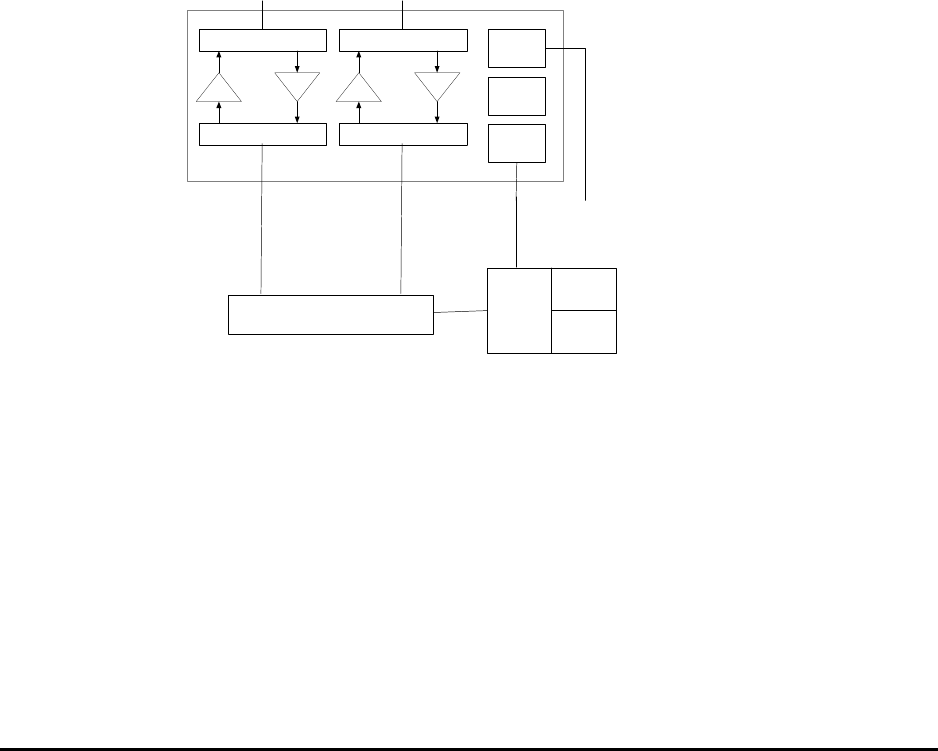
3.1 Schematic overview
Figure 1 shows a block-diagram of the LGP TMB system with an external
Control Interface Unit. For module functionality descriptions, see the following
sections. For technical data, refer to the “Specifications” part of this document
(Chapter 8).
The TMB system includes:
• a 2-carrier integrated Tower Mounted Booster unit (TMB)
• one Control Interface Unit (CIU)
• one software package
and various optional installation kits.
PA LNA
DUPLEXFILTER
DUPLEXFILTER
PA LNA
DUPLEXFILTER
DUPLEXFILTER
PSU
CSU
MODEM
TMB SYSTEM
MODEM
CONTR-
OLLER
COMM.
INTERFACE
BTS
Tx1/Rx1 Tx2/Rx2
POWER :
110 VAC,
230 V AC or
48 V DC
Comm.
CIU
ARP.1 ARP.2
Figure 1a. Functional diagram of TMB with external CIU
The TMB contains one dual duplexer for each carrier; one duplexer at the
antenna port and one duplexer at the BTS port. A high power amplifier (HPA)
is in the Tx path (downlink), and a low noise amplifier (LNA) is in the Rx path
(uplink).
The TMB contains a switch mode power supply unit (PSU). The power supply
is available as either an AC or a DC version (115/230 VAC or +48 VDC).
The micro controller (CSU) handles all monitoring of the TMB as well as
communication to the CIU. Communication to the CIU is achieved via the RF
modem.

MMP-10065-PB1.doc © LGP Telecom AB
11 (76)
The CIU is the main interface to the BTS. The CIU contains the physical
alarm interface to the BTS, which is relay contacts (3 pole), as well as the
infrared PC interface and the serial RS232 interface.
3.2 TMB-1900
The TMB-1900 is available in two configurations: With and without in-build
LNA.
The TMB-1900 with in-build LNAs is intended for Tower Top mounting close
to the antenna and is equivalent to TMB-900 and TMB-1800 as described in
figure 1a.
The TMB-1900 without LNAs is intended for base mounting close to the base
station and includes support (power supply and alarm interface) for four
external TMAs to be mounted close to the antennas. The functional diagram
is shown in figure 1b.
PA
DUPLEXFILTER
DUPLEXFILTER
PA
DUPLEXFILTER
DUPLEXFILTER
PSU
CSU
MODEM
MODEM
CONTR-
OLLER
COMM.
INTERFACE
BTS
Tx1/Rx1 Tx2/Rx2
POWER :
110 VAC,
230 V AC or
48 V DC
Comm.
CIU
TMA-
DD TMA-
DD
to ANT to ANT
CIN CIN
tower top
tower base
Figure 1b. TMB-1900 with external TMAs
MMP-10065-PB1.doc © LGP Telecom AB
12 (76)
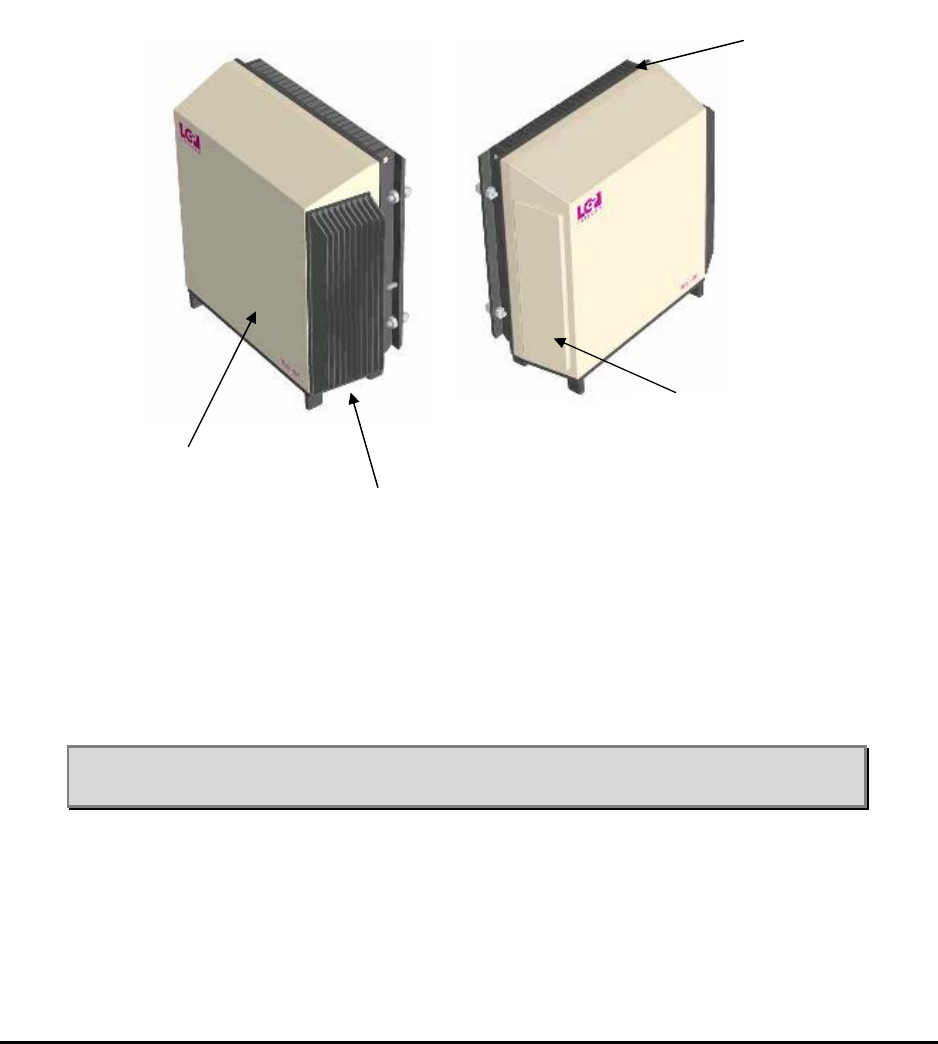
3.3 The TMB enclosure
The TMB enclosure is made of aluminium. All screws are made of stainless
steel. All metallic interconnections have seals which prevent dust and
humidity from entering the unit.
Figure 2 shows the mechanical layout of the TMB.
Figure 2 TMB mechanical layout
Front cover
The TMB front cover is attached to the large heat sink on the back of the unit
as well as to the bottom plate. The cover is made of aluminium.
Note: Do not remove the front cover. Unauthorised opening of the TMB will
destroy the seals and will void LGP Telecom’s product warranty.
Front cover
Side heat sink
Side ventilation
duct
Rear heat sink
MMP-10065-PB1.doc © LGP Telecom AB
13 (76)
Rear heat sink
The large heat sink on the rear of the TMB forms the back of the TMB. In
most installations the heat sink is protected from direct sun (solar radiation,
heat) due to the mounting plate and structure on which the TMB is fitted.
Although the TMB is designed to withstand direct sun, it is recommended to
prevent/minimise direct exposure to solar radiation.
The air-gap between the main heat sink and the mounting plate serves as a
“chimney”, to which airflow should not be restricted.
Note: Do not paint the heat sink.
Note: Do not restrict free airflow to the rear heat sink.
Side heat sink
The smaller heat sink located on the right hand side of the TMB provides
heat sink for the power supply.
Note: Restriction of free airflow to the heat sink must be avoided.
Note: Do not paint the heat sink.
Side ventilation
The left side of the TMB contains the ventilation system. The ventilation
design works in such a way that any moisture (condensation) inside the TMB
will be vented out. The arrangement will accept direct rain (tropical rain). The
unit is IP65 classified.
Note: Restriction of free air to this part must be avoided.
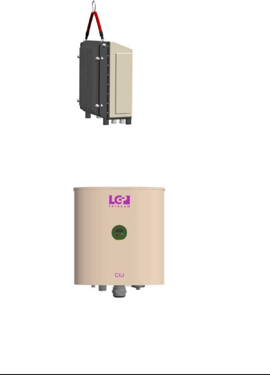
Handle
The handle is to be used when hand carrying the unit or lifting the unit up
onto a tower. The handle can be left attached to the TMB after installation
(recommended) or removed.
MMP-10065-PB1.doc © LGP Telecom AB
14 (76)
Figure 3 TMB with handle/lifting wire
3.4 Control Interface Unit (CIU)
Figure 4. CIU outline view
The CIU is the remote control element of the TMB system. The CIU handles
all communications with the BTS as well as a PC during setup.
Having the controller of the TMB system as a remote unit enables a flexible
installation. The CIU interfaces with the TMB via a RF modem using a coaxial
cable (TNC connector).

MMP-10065-PB1.doc © LGP Telecom AB
15 (76)
The small size of the CIU will in some cases allow for installation inside the
macro BTS. However, the CIU is shielded according to IP55 and does not
require additional weather protection. Therefore an outdoor installation of the
CIU next to a micro BTS is an example of an alternative highlighting the
flexibility of installation.
The CIU is powered via the communication cable between the TMB and the
CIU and does not need a separate power supply line.
The CIU contains three types of interfaces:
• RS232
• Alarm relay contacts
The alarm lines are relay contacts (closed or open). See “Operation” chapter
for more detail.
The CIU is the “master” and the TMB the “slave” in the overall control
architecture of the TMB system. Both the TMB and the CIU contains
microprocessors with peripheral memory circuits. The control architecture is
however very robust. In case the connection between the CIU and the TMB is
lost (broken cable) the TMB will continue service without interruption using its
current settings. However, no alarms or new settings can be handled until the
TMB/CIU interface is re-established.
Software updates (user interface software) can be downloaded into the CIU
via the RS232 interface. This software is stored in flash PROM. For
downloading procedure please see “Operation”.
RS-232 interface can also be used to remotely access the TMB using a
GSM-type modem or data-enabled handset. This is described in chapter 6.
MMP-10065-PB1.doc © LGP Telecom AB
16 (76)
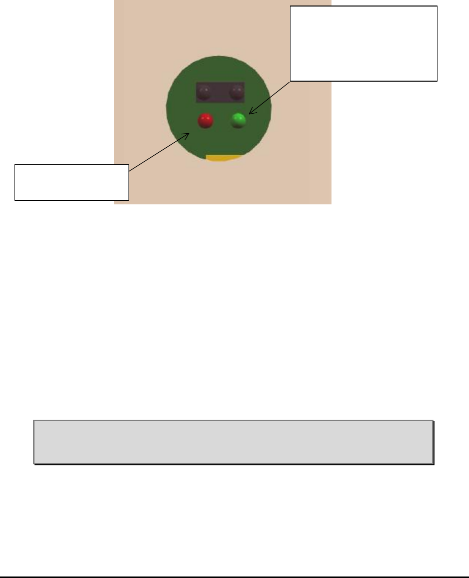
3.5 LED indicators
Figure 5 Zoom view of the LEDs on the CIU
There are no LED indicators on the TMB itself.
The CIU has two LEDs.
• A red LED (steady light) is indicating “TMB has alarm condition” and
service of the TMB system may be required, depending on the type of
alarm.
• A green LED (steady light) indicates “power on” and normal operation.
When flashing, it indicates that communication with the PC is in progress.
Note: The user can program the CIU in order to enable/disable all LEDs
making them non-visible; this, in example, if visible LEDs may
provoke vandalism of the equipment.
Green LED: normal operation
Flashing when
communicating with PC
Red LED:
alarm conditon

MMP-10065-PB1.doc © LGP Telecom AB
17 (76)
3.6 Antennas
The antennas are connected to the antenna ports (“ANT”) of the TMB via a
standard RF jumper cable and aligned traditionally to give coverage in the
intended area. Virtually any antennas can be used given the desired
coverage pattern. Dual polarised antennas can be used with one TRX on
each polarisation.
The only requirement is that the antenna isolation between the two TRX’s is
better than 30 dB (ETSI requirement for cross-polar antennas) to comply with
–120 dBm reverse intermodulation specification. Antenna isolation may on a
real site installation be lower than stated by the manufacturer due to
reflections. If the isolation of minimum 30 dB between antennas (or between
the two polarisations inside a dual polarised antenna) is not fulfilled, a
different frequency planning will solve the problem.
3.7 Feeder cables
The BTS feeder cables are connected to the TMB “BTS” port. Virtually any
type of RF feeders can be used. The concept of using TMBs means that the
high power is being generated at the antenna, which means that feeder loss
is relatively uncritical. As the power supply to the TMB is using a separate
cable, even thin lossy RF feeders can be used. Using thin RF feeders might
result in more flexible and easier installations.
Using thin RF feeders has also a big cost impact on the site cost.
Note: Using thin RF feeders, which result in high loss, will however mean
that the output power will be very low if the by-pass mode is
activated, as the total attenuation in this case is very high.
Note: Using thin RF feeder cables cannot be combined with the CIN
option.
Note: It is recommended to use jumper cables from the feeder lines to the
TMB to avoid stress in the connectors on the TMB.
3.8 Software diskette or CD
The TMB is controlled by a client software installed on a PC. The Windows
based software is supplied with the unit. Installation of the software is
described on the page that pops up on the screen when the CD is inserted,
or in the “readme.txt” file on the diskette. It is also described in chapter
“Configuration & Operation” of this manual.
MMP-10065-PB1.doc © LGP Telecom AB
18 (76)
3.9 CIU Cables
Various cables are supplied as options with the TMB. You may want to
configure your own cables, in this case consult “Installation”.
CIU – TMB comm. cable: The TMB is controlled by the CIU. A thin (RG58 or
similar) coaxial cable is needed to connect the two units. The cable type is
uncritical and maximum allowed cable attenuation between the CIU and the
TMB is 20 dB @10 MHz and 10 ohm DC resistance. This means that the
choice of communication cable type is relatively free and flexible allowing for
high degree of freedom in terms of installation.
Note: The cable must be fitted with watertight TNC type male connectors
at both ends. Proposed is Huber & Suhner type 11TNC–50-3-6 or
equivalent.
CIU – BTS alarm cable: The CIU-BTS alarm cable interfaces the TMB alarms
to the BTS via the CIU. There is a total of 4 alarm relays on the CIU available
for wiring up to the external alarm interface on the BTS. The relays have
three terminals allowing for either “normal closed” or “normal open”. The
wires are attached inside the CIU by simple screw terminals. The relays are
operated as failsafe. This means that the relays are engaged during normal
operation.
Note: Be sure to tighten the water tight cable gland arrangement for the
alarm cable.
CIU – RS232 cable: This cable provides the interface between the CIU and a
BTS controller or a PC - using the on-board RS232 interface connection on
the CIU.
Note: Place moisture cap on CIU’s RS232 connector when the RS232
cable is not attached.
See “Installation” concerning cable configuration.

MMP-10065-PB1.doc © LGP Telecom AB
19 (76)
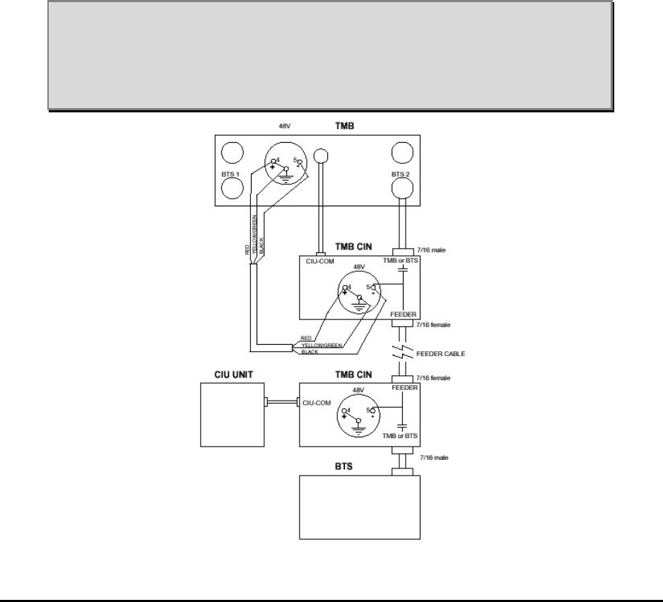
3.10 Alternative installation using only RF feeders (CIN option)
A Current Injector (CIN) option is available for the 48V DC version of the
TMB. This eliminates the need for a separate power cable and the CIU-TMB
cable. A CIN is mounted external to the TMB on the BTS2 port. A similar CIN
is then mounted at the BTS on the feeder that connects to BTS2 of the TMB.
The DC power to the TMB and the communication between the TMB and the
CIU is now all done on one of the RF feeders.
In this case the CIU will be connected to the BTS CIN. The 48V supply will
also be connected to the BTS CIN.
The details of the CIN installation is described in chapter 4.10.
3.11 Alarms
The following table shows the available alarms on the TMB (per carrier).
Uplink minor (one LNA) failure
Uplink major (both LNA’s) failure
Downlink minor (HPA) failure
Downlink major (HPA) failure
Temperature high/low
Input power overload
Output power overload
VSWR above threshold (available at additional cost)
TMB communication error
TMA alarm (TMB-1900 only)
All alarms can be monitored on the O&M interface. A total of 4 relays (12
wires) are available from the CIU to the BTS. Software configuration
determines which alarms are presented to the BTS. Normally closed (NC) or
normally open (NO) for all relays can be configured independently.
The relay operation is ‘fail-safe’, meaning that the relays will engage during
normal operation, and will disengage when there is an alarm condition. This
also means that a power failure will generate an alarm condition.
The TMB system operates with “Auto Recovery”, meaning that it
automatically will try to come back to normal operation / performance
following an alarm situation.
MMP-10065-PB1.doc © LGP Telecom AB
20 (76)
3.11.1 Uplink failure
Uplink failure alarm has two levels, minor and major. This alarm is indicating
that the low-noise amplifiers are deviating from original setting/performances.
The uplink LNA amplifiers are balanced, i.e. two LNA devices working in
parallel for each carrier.
A minor alarm will be activated if one of the LNA amplifiers of a balanced pair
is failing. A major alarm is activated if both LNAs are out of operation.
It is configurable by software, what action shall be taken upon an uplink
failure. You have the choice between:
For Uplink Minor alarm For Uplink Major alarm
Alarm only Alarm only
Increase gain in LNA By-pass mode
“Increase gain in LNA”: An action that can be set to compensate for a failing
transistor. In this case the “surviving” transistor will “attempt” to bring back the
uplink gain to the original value by increasing its gain and thereby
compensate for the failing transistor. This can be used if the uplink gain is set
lower than the maximum gain (12 dB).
“By-pass mode”: The by-pass relay will be activated upon a transistor failure,
and the entire uplink LNA amplifier by-passed.
“Alarm only”: This setting will only report an uplink amplifier failure, but will
take no further action.
3.11.2 Downlink failure
The downlink failure alarm has two levels, minor and major. This alarm
indicates that the power amplifiers are deviating from original
setting/performance.
A minor alarm will be generated if the TMB system automatically reduces the
output power, either because of “output overload” (see below) or because of
an internal decision by the system in order to prevent destruction of the TMB
(see below as well). The TMB system will revert to normal setting when the
fault condition disappears.
Downlink major failure alarm will be generated if there is a fatal error with the
power amplifiers, i.e. transistor failure. Upon such a failure, the PIN diode
switch will be activated automatically and will by-pass the power amplifier.
3.11.3 Temperature high/low
The temperature inside the TMB is monitored at three test points: on the two
power amplifiers and on the power supply. The temperatures are shown on
the Info or Status menu in the control software.

MMP-10065-PB1.doc © LGP Telecom AB
21 (76)
The “Temperature Low” alarm is a minor alarm and may show up at cold
start, when the TMB is started up from extreme cold temperatures like –40
ºC. In this extreme situation the TMB may run with reduced output power until
the temperature inside the TMB has reached a level where it is safe to run
the TMB with max output power (2 x 20 W).
This “Temperature Low” alarm will not be set, if the TMB is already running in
normal traffic mode and the outside temperature falls to- 40 ºC. In this case
the self heating of the TMB is sufficient to maintain full performance.
“Temperature High” alarm will be set, if the TMB gets overheated. The TMB
is designed for an ambient temperature of up to +55 ºC and designed to be
exposed to direct sunlight. However, in order to protect the TMB from
destruction and ensure prolonged trouble-free operation (high MTBF), the
system monitors extreme high temperatures.
At a “Temperature High” alarm a minor alarm will be sent and the TMB will
automatically reduce the output power gradually and ensure that the internal
temperature does not exceed +85 ºC.
When this “normal” temperature level is reached the TMB will revert to its
original power setting. This reduction of output power is considered a
‘downlink minor alarm’.
3.11.4 Input overload
The TMB is designed to withstand +43 dBm input power (20 W). Exceeding
+43 dBm may damage the TMB.
The “Input Overload” alarm will be raised when the input power level is
reaching a critical high level. The input power level will together with the
current gain setting determine how strong the internal circuitry (bypass,
power amplifiers, etc.) is driven. In other words: is there a risk of product
destruction, extreme intermodulation levels, etc.?
In this case the TMB will automatically reduce the gain to avoid overload and
thereby prevent the TMB from saturation and destruction.
If the TMB downlink gain is already set at minimum (5 dB) the gain cannot be
reduced further and the system is not able to compensate for this false
operation of input overload.
The input overload alarm will always be preceded by the output overload
alarm, as the output saturates before the input is damaged.
3.11.5 Output overload
The TMB is designed to run at maximum 20 watt output power (+43 dBm).
Exceeding +43 dBm output power results in the power transistors entering
their saturation level and the heat generation will increase dramatically.
If the TMB is operating with a certain gain value, which results in full output
power (+43 dBm), and the input power is subsequently increased, then due
to the fixed gain, the power amplifiers will be pushed into saturation.

MMP-10065-PB1.doc © LGP Telecom AB
22 (76)
A saturated power amplifier will generate intermodulation and may cause
interference. Overheating of the TMB will reduce the lifetime of the TMB
(MTBF). Consequently the TMB system will send an “Output Overload” alarm
and reduce the gain to a non-critical setting.
3.11.6 VSWR over threshold
The TMB can be provided with an antenna Voltage Standing Wave Ratio
(VSWR) monitor built into the system (optional). The VSWR alarm is not an
exact return loss measurement, but a simple broad band detection of the
termination impedance at the Antenna port of the TMB.
The VSWR alarm sensor is capable of detecting a poor antenna VSWR, i.e.
when the antenna is not present or the jumper cable is defective.
The VSWR function is only operational between 5W and 20W output power
(37 - 43 dBm).
Nominal VSWR threshold is 4.5:1 (Return Loss equal to 4 dB). This will
guarantee an actual threshold between 1 and 8 dB (all phases).
3.11.7 TMB communication error
3.11.8 TMB fail
Not implemented. Reserved for future use.
3.11.9 TMA failure
This alarm is only used for TMB-1900 with external TMAs.
The current consumption of the TMAs is measured by the TMB and if outside
limits (<40 mA or >160 mA), an alarm is raised.
The TMA power supply also has short circuit protection which turn off the DC
at a current higher than 300 mA.

MMP-10065-PB1.doc © LGP Telecom AB
23 (76)
4 Installation
4.1 Safety precautions
The TMB is intended for professional use and must be installed by
qualified personnel only.
Please pay close attention to the following safety precautions before
handling, installing and operating the TMB:
• The TMB does not contain any serviceable parts inside. Do
not open the TMB.
• The TMB might have sharp edged on the heat sinks. Use
durable gloves when handling the TMB.
• When the TMB is in operation, the heat sinks are hot, up to
80°C. Do not touch heat sinks.
• The TMB does not radiate (microwave , X-ray, radioactive) by
itself, but only when connected to antennas. Do not touch
antennas connected to a TMB in operation.
• Keep clear of antennas connected to a TMB in operation
(microwave radiation).
• The grounding wire must be installed before connecting the
power supply. The grounding is protective.
• All cables must be connected before the TMB is turned on.
Please contact LGP Telecom if in any doubt about handling, installing
or operating the TMB.

MMP-10065-PB1.doc © LGP Telecom AB
24 (76)
4.2 Unpacking the equipment
The TMB and its accessories are packed in a strong cardboard box, to
protect them from damage in transit. We recommend that this crate is kept for
future transportation.
After unpacking the TMB, check that the equipment, as indicated by its type
label, corresponds to the order.
Note: Warranty is only valid if original TMB crate material is used when
returning the unit.
4.3 Checking the equipment
Before mounting, check that the equipment is complete and unharmed.
The TMB standard package contains the following parts.
Standard delivery:
1. TMB unit
2. Mounting plate for the TMB
3. CIU unit
4. Mounting plate for the CIU
5. Power supply connector for the power supply cable
6. Two TNC connectors
7. Test sheet incl. unit specific data (S/N, hard- and software version etc.)
8. Simple mounting instruction
9. TMB/CIU interface cable, 30 meters
Following options may also be in the box:
1. TMB installation kit which consists of:
• Handle / lifting wire
• RS232 cable to the PC (4 meter)
• Disk or CD containing PC software
• Technical Product Manual (this document)

MMP-10065-PB1.doc © LGP Telecom AB
25 (76)
2. Pole mounting brackets incl. bolts and nuts
• Two inner clamp halves
• Two outer clamp halves, each with 2 holes and a reinforced M8
thread
• Four M8 × 12 mm bolts, for securing the inner clamps to the
mounting plate
• Four M10 × 200 mm bolts, for joining the inner and outer clamp
halves, when mounting to a vertical pole having a diameter of
90 – 140 mm.
• Four M10 × 140 mm bolts, for joining the inner and outer clamp
halves, when mounting to a vertical pole having a diameter of
60 – 90 mm.
3. Current Injector Kit.
• CIN for mounting by TMB
• CIN for mounting by BTS
• Short TNC cable
• Long TNC cable
• Short DC supply cable
4. Remote Access Cable.
• RS-232 cable to modem
Other items, such as AC/DC power supply cables, RF jumpers etc. will also
be needed for the job, but should be provided by the installer and is therefore
not specified here.
4.4 Attentions prior to installation
Rear heat sink
In most installations the heat sink is protected from direct sun (solar radiation,
heat) due to the mounting plate and structure on which the TMB is fitted.
Although the TMB is designed to withstand direct sun, it is recommended to
prevent/minimise direct exposure to solar radiation.
Note: Do not paint the heat sink.
Note: Do not restrict free airflow to the rear heat sink.

MMP-10065-PB1.doc © LGP Telecom AB
26 (76)
Side heat sink
The smaller heat sink located on the right hand side of the TMB provides
heat sink for the power supply.
Note: Restriction of free airflow to the heat sink must be avoided.
Note: Do not paint the heat sink.
Side ventilation
The left side of the TMB contains the ventilation system. The ventilation
design works in such a way that any moisture (condensation) inside the TMB
will be vented out. The arrangement will accept direct rain (tropical rain). The
unit is IP65 classified.
Note: Restriction of free air to this part must be avoided.
MMP-10065-PB1.doc © LGP Telecom AB
27 (76)
4.5 Equipment and tools for mounting
4.5.1 Carrying / lifting handle
The carrying handle / lifting wire is used to carry the TMB by hand or when
lifting the TMB in a wire. The handle is easily attached to the bolts found on
the back upper most of the big heat sink. The handle can be left on the TMB
after installation (recommended) or removed.
Figure 6 TMB with handle
Note: The handle should be removed after the installation. Replace the
bolts when the handle has been removed.
4.6 Hoisting the TMB
The handle can be used for hoisting the TMB by attaching a rope or wire to it.
Note: The wire uses for hoisting MUST be fixed to the loop of the
handle.
When hoisting a TMB it is strongly recommended that you
ensure the TMB from banging into the tower etc. by having a
steering rope from the TMB and down to the ground.
Handle / lifting wire is
connected to the two
bolts located on the big
heat sink.
MMP-10065-PB1.doc © LGP Telecom AB
28 (76)
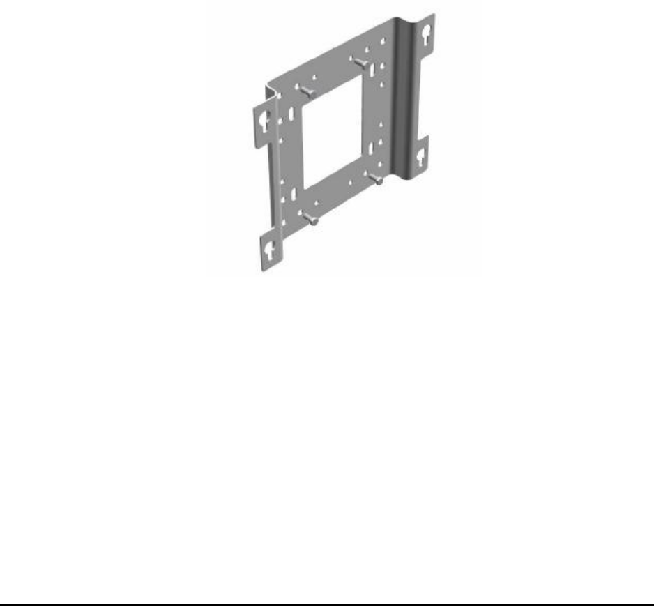
4.7 Mounting the TMB on a wall
Wall mounting comprises two steps:
Securing the mounting plate to the wall
Fitting the TMB to the mounting plate
Securing the mounting plate
The holes in the mounting plate can be used for securing the plate to the
wall, as shown below. If necessary, new holes may be drilled in the plate, as
long as this does not detrimentally reduce the strength of the mounting plate.
The installer decides how to fit the plate to the wall. However, in order to
ensure proper cooling and ventilation, the TMB must be installed in vertical
position.
Figure 7: Install the mounting plate on a wall using normal plugs and
screws. Use existing holes in the mounting plate, or drill
new ones as required.
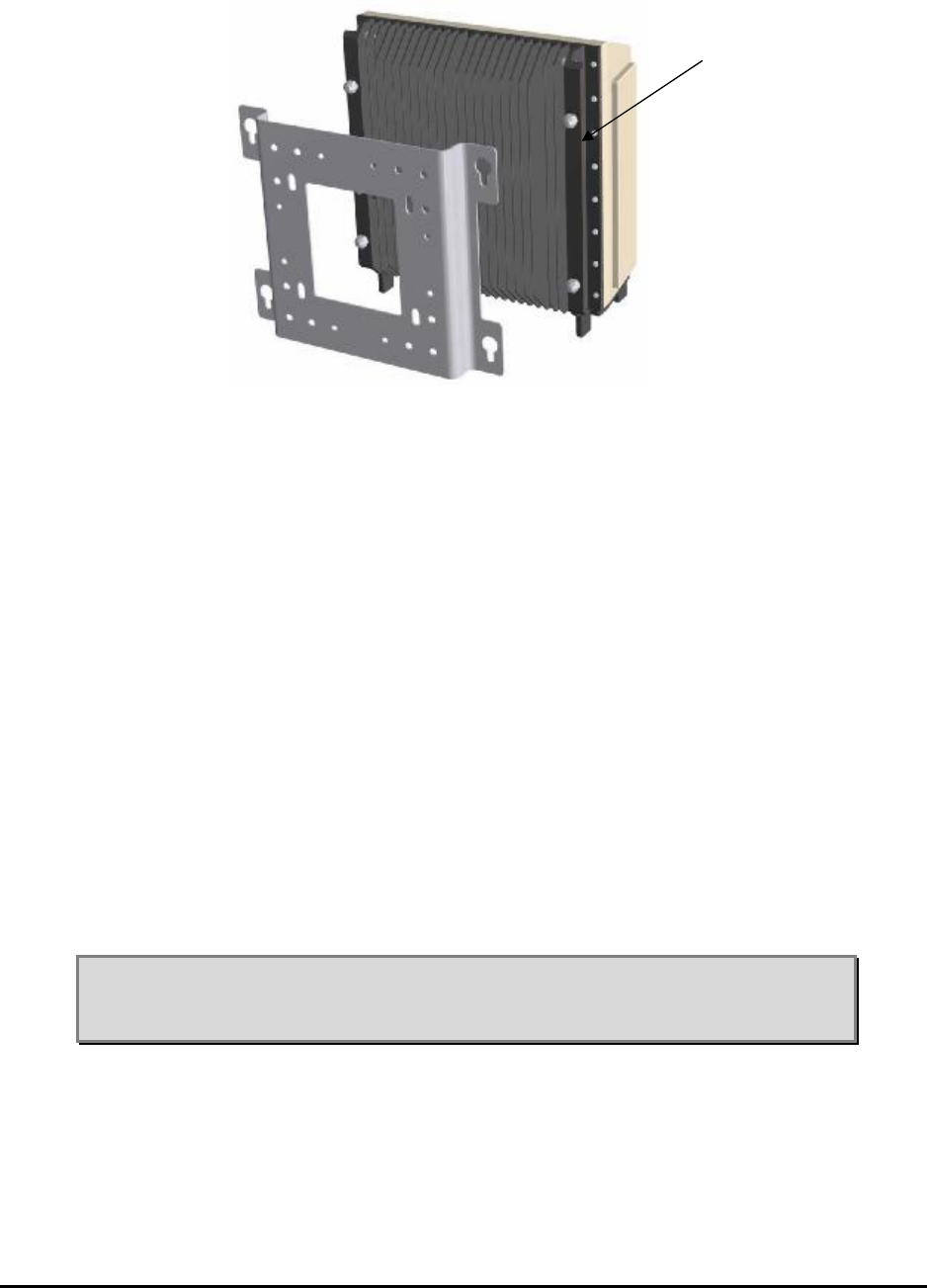
Mounting the TMB
Fit the TMB to the mounting plate and tighten the screws to a torque of 40
Nm.
MMP-10065-PB1.doc © LGP Telecom AB
29 (76)
Figure 8: Loosen the four big mounting screws on the back of the
TMB. Fit the TMB to the mounting plate and tighten the
screws to a torque of 40 Nm.
4.8 Mounting the TMB on a vertical / horizontal pole
The pole mounting hardware is designed for pole diameters in the range of
60 mm – 140 mm (2.4" – 5.5"). For your convenience, two sets of bolts are
found in the mounting gear.
• M 10 x 140 mm for pole diameter: 60 – 90 mm
• M 10 x 200 mm for pole diameter: 90 – 140 mm
Mounting the TMB on a vertical pole comprises two steps:
• preparations on the ground
• mounting.
Before installing the heavy TMB, install the mounting plate on the pole using
the procedure described below.
Note: The TMB must always be installed upright to ensure best
cooling. If at all tilted make sure the TMB is tilted backwards and
maximum 5 degrees.
Mounting screws must
be loosened prior to
mounting
MMP-10065-PB1.doc © LGP Telecom AB
30 (76)
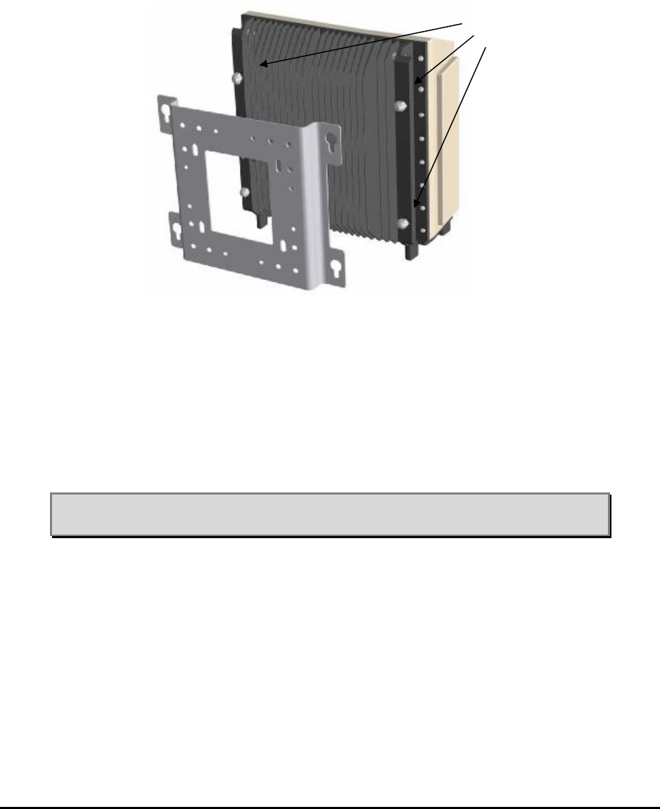
On the ground
Step 1: Check that the four mounting screws on the back of the TMB are un-
tightened to the extent of slotting on to the mounting plate. The
screws cannot drop out. Fig. 9.
Figure 9: Un-tighten the four mounting screws on the back of
the TMB before you hook it onto the mounting
plate.
Note: Check that all four screws leave enough space for the mounting
plate.
Mounting screws must
be loosened prior to
mounting
MMP-10065-PB1.doc © LGP Telecom AB
31 (76)
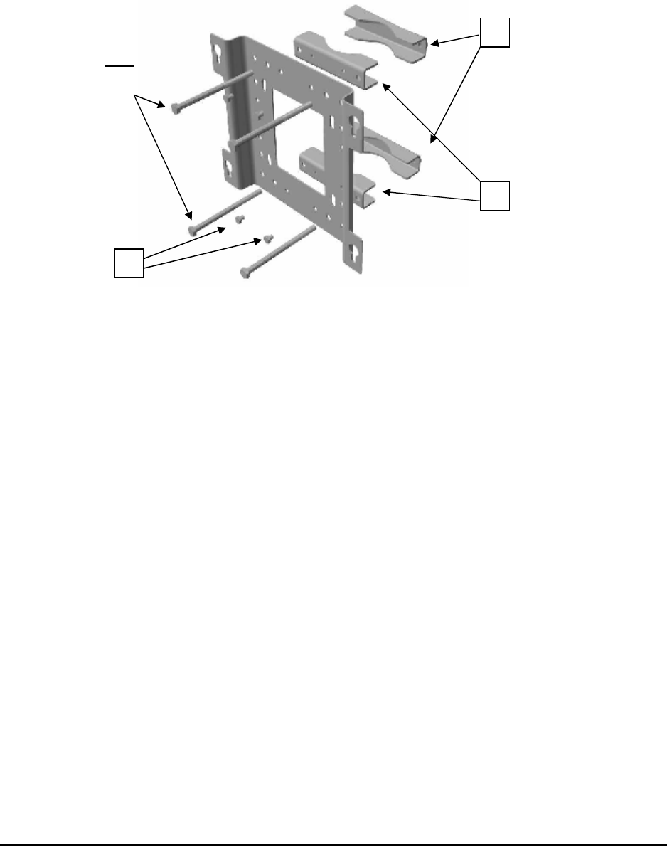
Step 2: Join the inner clamp halves (1) and the mounting plate, using the
four M8 × 12 mm bolts (2). Tightening torque, 21 Nm. See figure 10.
Figure 10: Fix the inner clamps to the mounting plate by using the
four small screws.
Step 3: Then mount the outer clamps (3) loosely, each with one of the long
bolts (4) (M 10 × 200 mm or M 10 x 140 mm). Check that there is
enough space for the pole. See figure 10.
Step 4: Finally check that the two remaining long bolts (4) are accessible.
Mounting
There are two stages involved in mounting the TMB on a vertical pole:
Step 1 Clamping the mounting plate to the pole
Step 2 Fitting the TMB to the mounting plate
Clamping the mounting plate to the pole
Position the clamps around the pole and insert the two remaining long bolts
(M10 × 200 mm or M10 x 140 mm). Position (4) on figure 10. Tighten all four
bolts, taking care to keep the two halves of each clamp parallel. See figure
11.
1
2
4
3
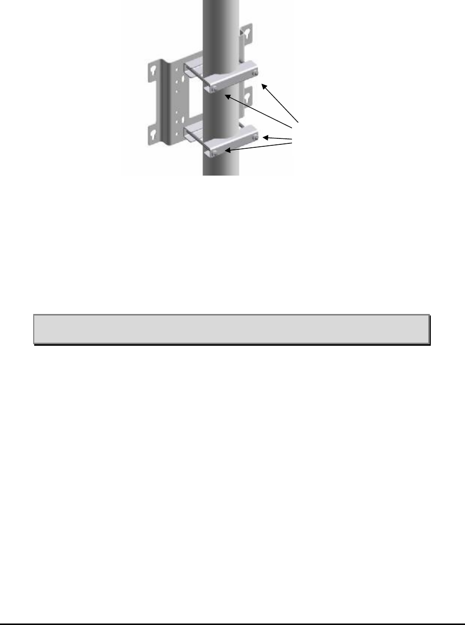
MMP-10065-PB1.doc © LGP Telecom AB
32 (76)
Figure 11: Fixing the mounting plate on a pole.
Finally, tighten the bolts to a torque of 25 Nm.
Note: Be sure to tighten the bolts hard on the pole in order to prevent the
TMB from turning around the pole during high wind load.
Fitting the TMB to the mounting plate
First pass the heads of the screws through the keyhole slots in the mounting
plate and lower the TMB until the screw heads are retained by the narrow
lower portions of the slots, see figure 12.
Tighten the screws to a torque of 40 Nm.
Tighten the
bolts
MMP-10065-PB1.doc © LGP Telecom AB
33 (76)
Figure 12 Insert the heads of the screws through the keyhole slots in
the mounting plate and lower the TMB until the screw
heads are retained by the narrow portions of the slots. (2):
Tighten the screws.
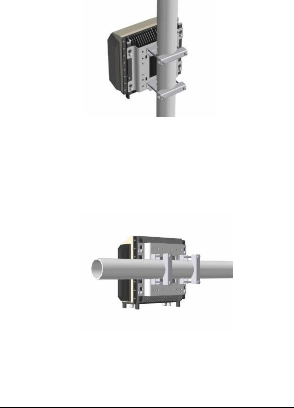
The TMB can also be mounted on a horizontal pole using the same
hardware, as shown below in figure 13.
Figure 13 The TMB mounted on a horizontal pole
MMP-10065-PB1.doc © LGP Telecom AB
34 (76)
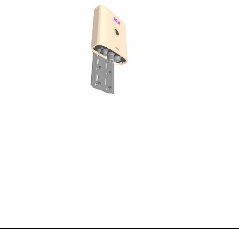
4.9 Mounting the CIU
The CIU comes with a small mounting plate. The plate is prepared for wall
mounting as well as pole mounting.
For wall mounting use two or four screws appropriate to the nature of the
wall.
In case of pole mounting use the metallic belt.
The CIU slides on to the mounting plate and is locked in position with the lock
screw (Allen key) on the side of the CIU. The Allen key is part of the
installation kit.
Figure 14 The CIU can be wall or pole mounted using the small
mounting place.
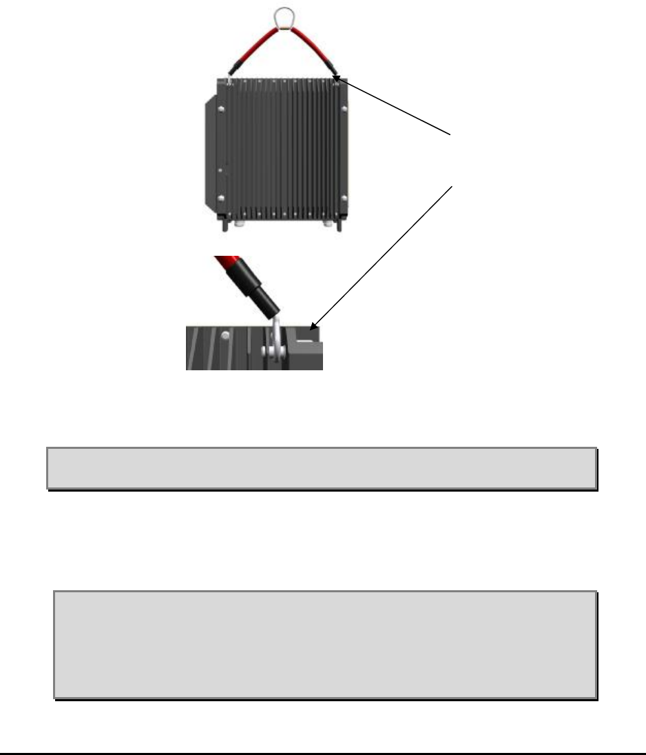
4.10 Connecting the TMB and CIU
4.10.1 Connecting the earth cable
The TMB cabinet must be connected to earth. For this purpose, it has an M6
bolt in the lower left corner (when looked at from behind) with a locking
washer and a nut.
Fit the lug of the earth cable over the bolt and then fit the locking washer.
Secure the lug and washer with the outermost nut.
Minimum cable size for ground connection: AWG 4. Use green/yellow cable.
MMP-10065-PB1.doc © LGP Telecom AB
35 (76)
Figure 15 Grounding stud is found on the right hand side of the big heat
sink.
Note: It is recommended to use a 16 mm² cross section grounding wire
(AWG 5)
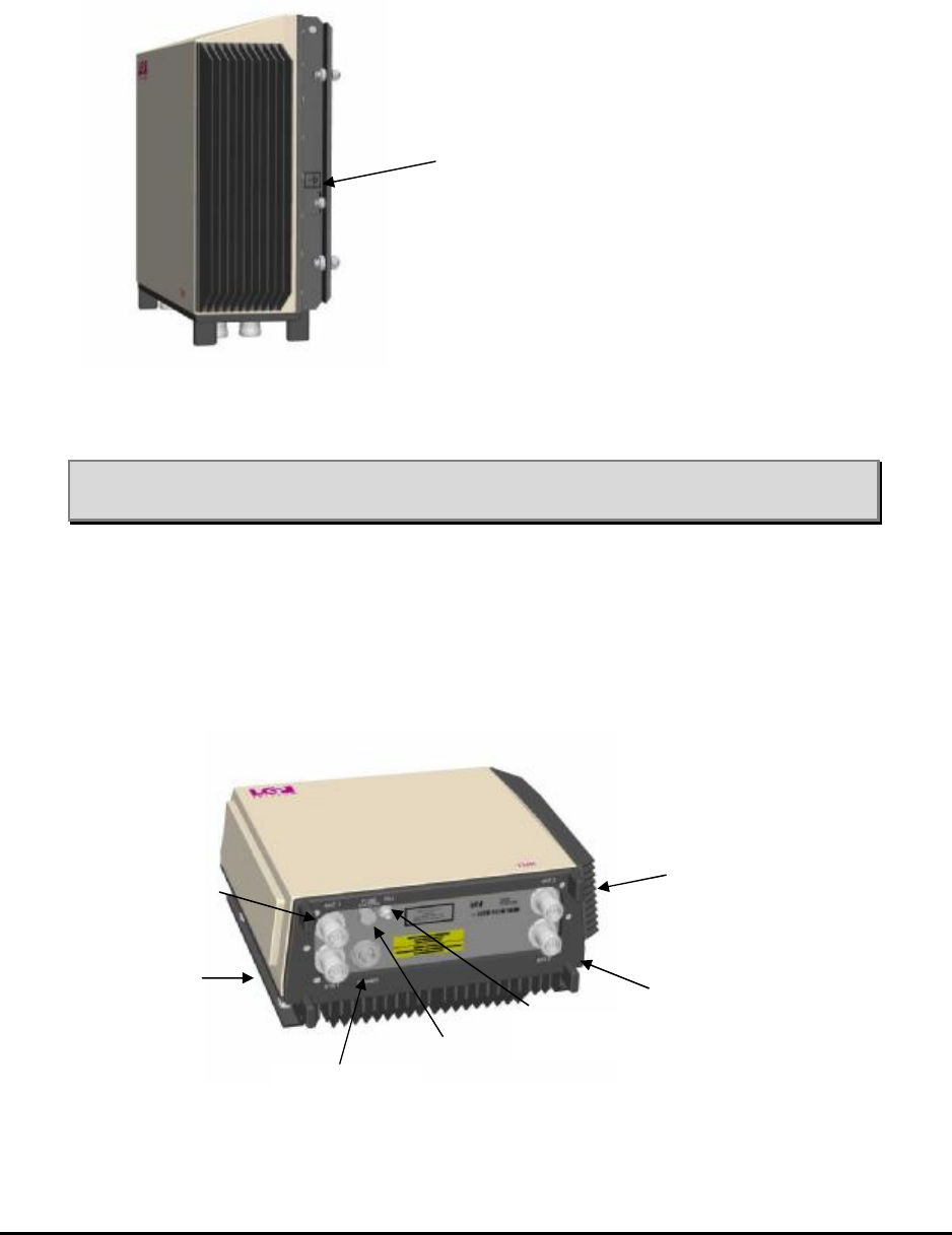
4.10.2 Connecting the RF feeder cables
Connect the RF feeder cables to the respective RF connectors at the bottom
plate of the TMB. The RF connectors are clearly marked “Antenna” and
“BTS”.
Figure 16 All connectors are found on the bottom plate of the TMB, giving
the best natural weather protection. All connectors are clearly
marked.
Grounding
screw
Antenna # 1 Antenna # 2
BTS # 2
Power
connector
CIU interface
Fuse
BTS # 1
MMP-10065-PB1.doc © LGP Telecom AB
36 (76)
Note: Be sure always to connect the RF feeder cables and the
grounding wire before the power cable. The power plug is made
of rigid plastic, but it can be broken by a big spanner used to
tighten the RF feeders.
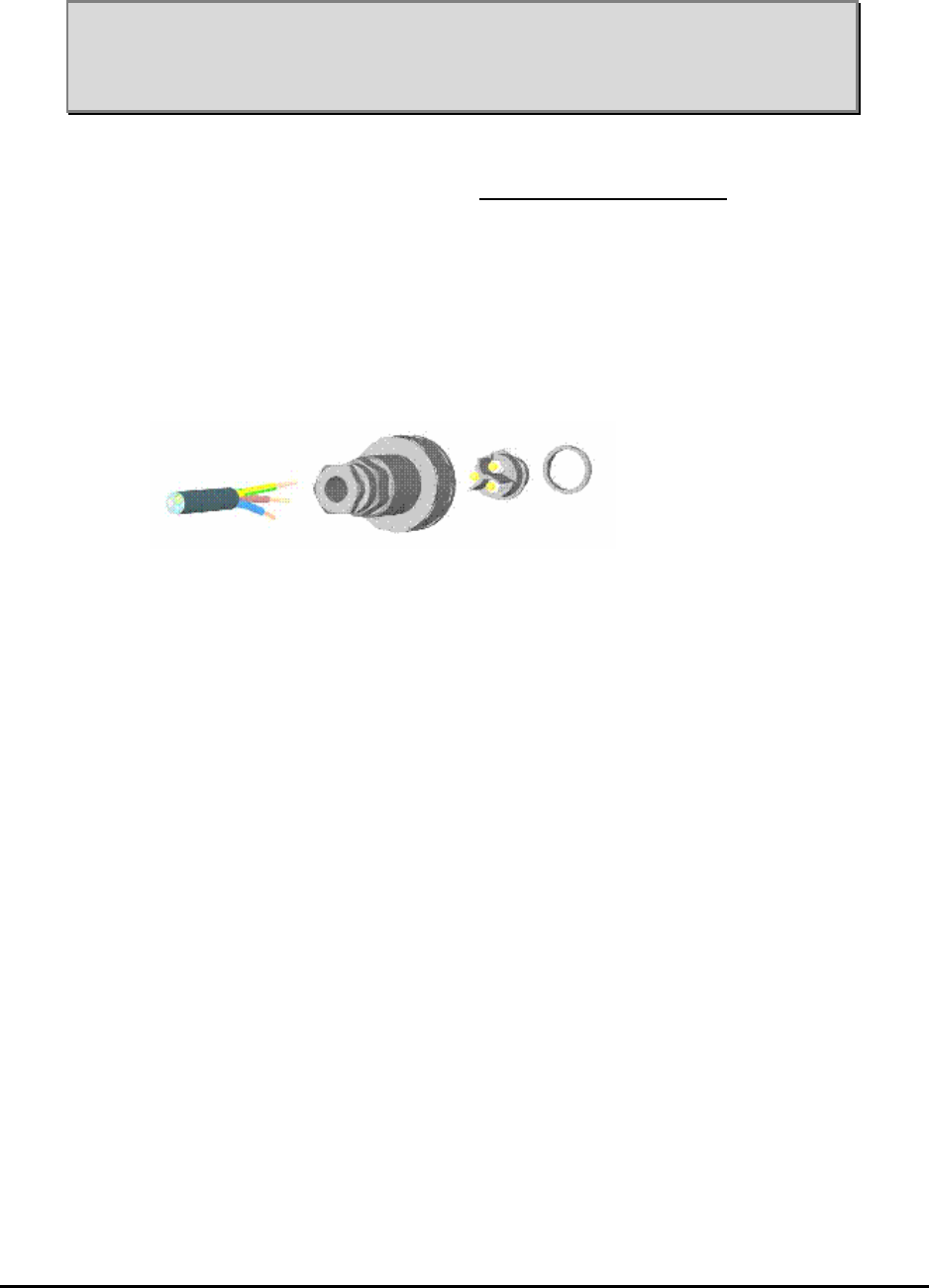
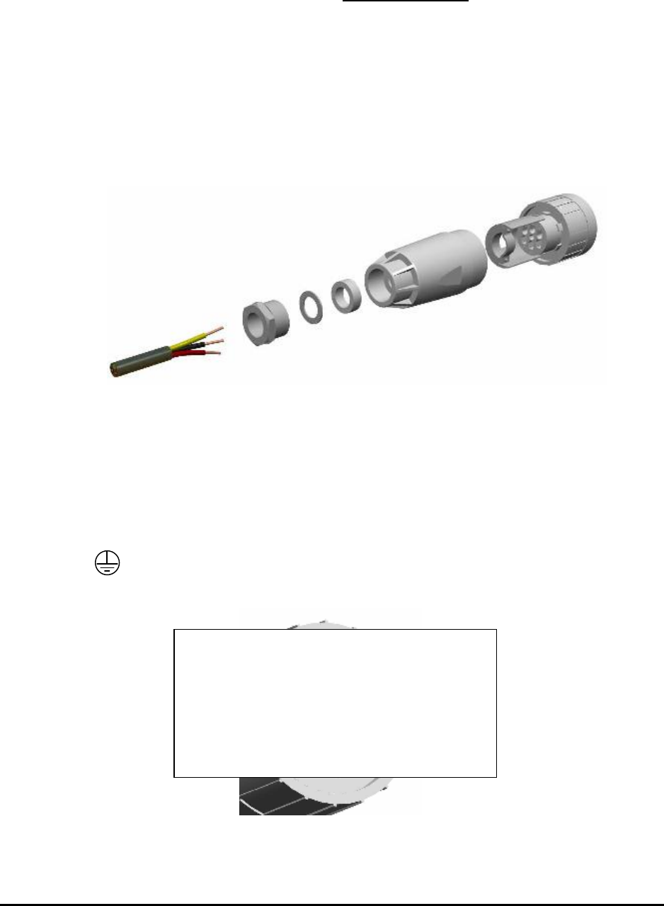
4.10.3 Configuring a power supply cable for 115V/230V AC versions
The TMB is supplied with a female connector for the power cable fitting.
Disassemble the connector as shown below by un-screwing the small front
ring.
Un-tighten the cable retaining nut and guide the power cable through.
The maximum outer dimension of the power cable is 6-8 mm.
Figure 17 Power supply connector shown disassembled.
The connector has three terminals. They are clearly marked:
N = Neutral
L = Line (phase or Live)
0 = Earth (ground)
Cable recommendations:
UV resistant
LS0H (Low Smoke, Zero Halogen)
Outdoor cable
Extended temperature range
MMP-10065-PB1.doc © LGP Telecom AB
37 (76)
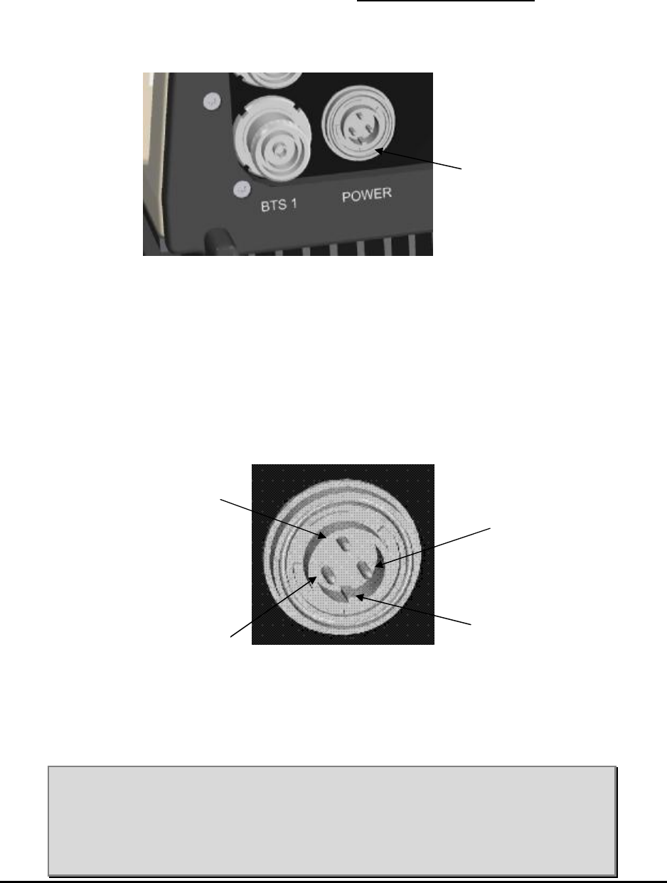
4.10.4 Connecting the power supply cable for 115V/230V AC versions
The TMB has always a preinstalled power supply connector (male) located at
the bottom plate.
Figure 18 Close up view of the TMB bottom plate where the power
supply connector (AC) is located.
Power supply connector type: Bulgin mini Buccaneer IP68
Pin configuration of male connector (front view):
Figure 19 Enlarged view of the pin configuration of the power supply
connector (AC) placed at the bottom of the TMB.
Note: It is recommended that the power supply cable is properly
dimensioned and securely attached to the tower/building.
Note: It is recommended that the main power supply cable from the
base/BTS is terminated in a small interconnection box, from
which a short jumper is routed to the TMB power inlet connector.
Phase
Power supply
connector
Neutral
Guide / grip
Ground
Live/phase

MMP-10065-PB1.doc © LGP Telecom AB
38 (76)
Note: It is recommended that the main power supply cable for the TMB
is connected to a separate circuit breaker at the base.
Figure 20 The TMB shown with a small power interconnection box
installed right next to the TMB.
4.10.5 Specifications for the AC input voltage
The AC input voltage for the 115V/230V AC version accepts all voltages in
the range of 85 V – 265 V AC. However, for power-factor correction to be
active the input voltage must be in the range of 85 V – 255 V AC.
The cable must have a maximum resistance of 2.5 ohms (both wires total)
between the AC supply and the TMB.
Interconnection box
Small power
cable jumper
MMP-10065-PB1.doc © LGP Telecom AB
39 (76)
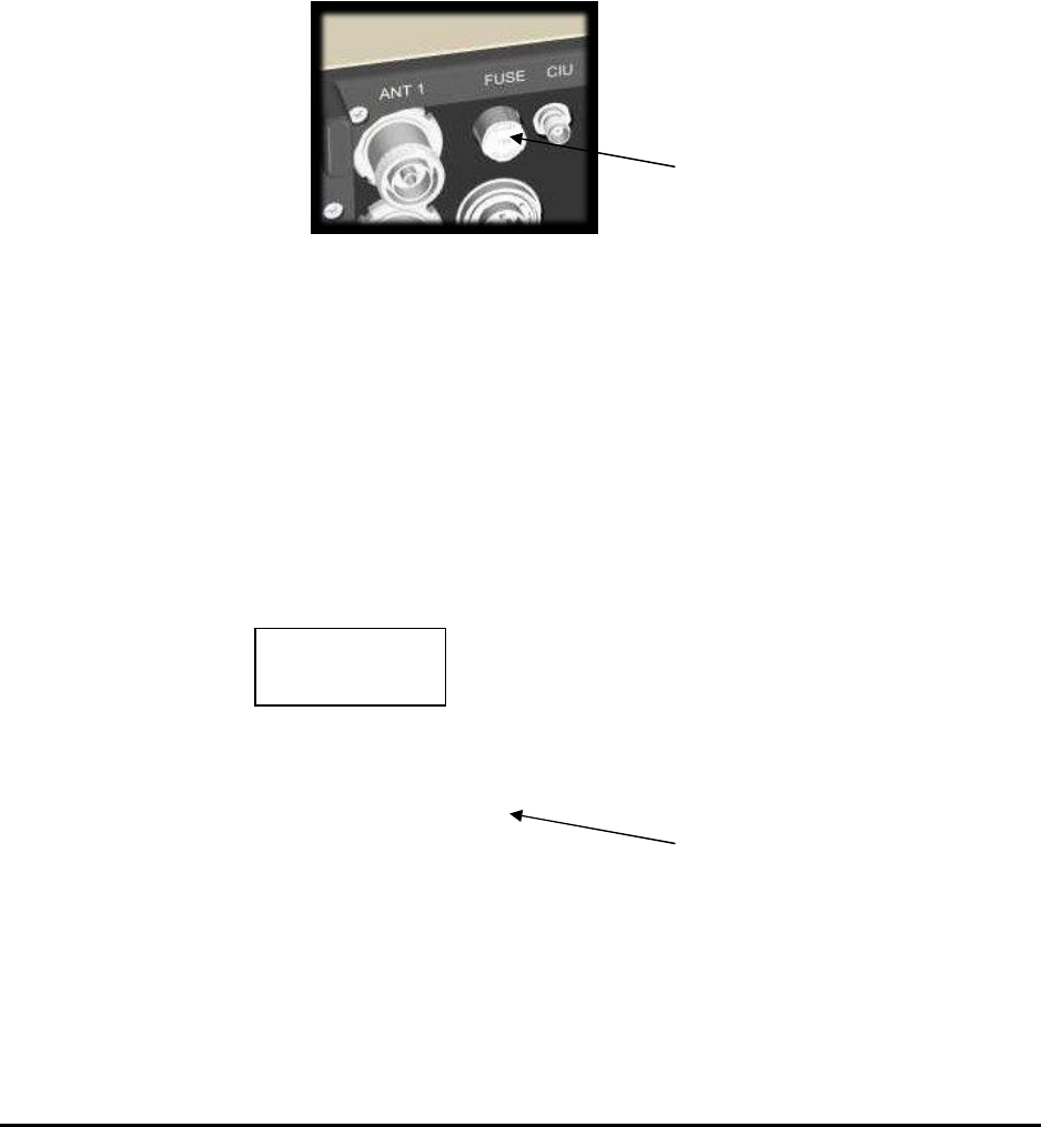
4.10.6 The fuse for TMB-900 and TMB-1800 (AC version)
The AC versions of TMB-900, TMB-1800 has a fuse located at the bottom
plate. The fuse is required by regulations.
Fuse type (AC versions): 5 mm, 6.3A slow
Recommended type: Wickmann series 19181, 6.3 A or similar.
Figure 21a. The fuse on the TMB is located at the bottom of the TMB
at the connector plate.
4.10.7 The fuse for TMB-1900 (AC version)
The AC versions of TMB-1900 has a fuse located at the bottom plate. The
fuse is required by regulations.
Fuse type:
Recommended type: .
Figure 21b. The fuse on the TMB is located at the bottom of the TMB
at the connector plate.
TMB fuse
TMB fuse
Billede
MMP-10065-PB1.doc © LGP Telecom AB
40 (76)
4.10.8 The fuse for TMB-1900 (DC version)
The DC versions of TMB-1900 has a fuse located at the bottom plate. The
fuse is required by regulations.
Fuse type:
Recommended type: .
Figure 21c. The fuse on the TMB is located at the bottom of the TMB
at the connector plate.
TMB fuse
Billede
MMP-10065-PB1.doc © LGP Telecom AB
41 (76)
4.10.9 Configuring a power supply cable for 48V DC versions
The TMB is supplied with a female connector for the power cable fitting.
The type is: Amphenol C016 20E005 103 2
Disassemble the connector as shown below by un-screwing the small front
ring.
Un-tighten the cable retaining nut and guide the power cable through.
The maximum outer dimension of the power cable is 13 mm.
Figure 22 Power supply connector shown disassembled.
The connector has five (5) terminals. The following terminals are used:
Terminal 4 = plus (+), the positive 48V DC
Terminal 5 = minus (-), the negative 48V DC
= Earth (ground)
Figure 23 Connections shown from the back of the connector.
Nyt billede, som fig. 19
MMP-10065-PB1.doc © LGP Telecom AB
42 (76)
Note: Inside the TMB, the plus (+) and minus (-) are isolated from
ground. This makes it possible to wire the TMB as a
+48V DC or a –48V DC.
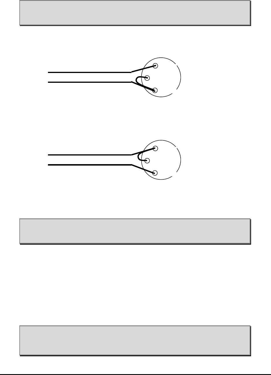
To configure the TMB for a positive (+48V) voltage relative to ground,
connect like this:
+48V
GND
To configure the TMB for a negative (-48V) voltage relative to ground,
connect like this:
GND
-48V
Note: It is VERY IMPORTANT that + and – are connected correctly to
the terminals of the power connector. Failure to do so will
damage the TMB permanently.
Cable recommendations:
UV resistant
LS0H (Low Smoke, Zero Halogen)
Outdoor cable
Extended temperature range
Note: It is recommended that the power supply cable is properly
dimensioned and securely attached to the tower/building.
4
4
4
GND
p.4=+
p.5=
−
4
4
4
GND
p.4=+
p.5=
−
MMP-10065-PB1.doc © LGP Telecom AB
43 (76)
Note: It is recommended that the power supply cable from the
base/BTS is terminated in a small interconnection box, from
which a short jumper is routed to the TMB power inlet connector.
4.10.10 Specifications for the DC input voltage
The 48 V DC version of the TMB accepts all DC voltages in the range of 36 V
to 76 V DC. Be aware that the current will increase for a lower voltage. It is
recommended that the DC power cable is chosen so that the input voltage
will never be lower than 40 V DC.
The cable must have a maximum resistance of 0.75 ohms (both wires total)
between the 48V supply and the TMB. This results in the following
recommended wire gauges:
Cable size Max. length (between TMB
and Power Source)
mm2 AWG no. Meters feet
1.0 17 20 66
1.5 15 30 98
2.5 13 50 164
4.0 11 80 262
6.0 9 120 394
4.10.11 Connecting the CIU/TMB communication cable
The TMB may be delivered with or without CIU communication cable.
In case the CIU communication cable has been ordered and supplied with
the TMB unit, it is already fitted with TNC connectors in both ends. In this
case connect it to the clearly marked “CIU” connector at the bottom plate.
In case the TMB is ordered without CIU communication cable, use the two
TNC connectors delivered with the TMB with an RG58 cable or use any other
shielded 50 ohm cable that meets the requirements, see below.
CIU communication male connector type: TNC. Proposed type is Huber &
Suhner type 11 TNC–50-3-6 or equivalent.
MMP-10065-PB1.doc © LGP Telecom AB
44 (76)
Cable recommendations:
UV resistant
LS0H (Low Smoke, Zero Halogen)
Outdoor cable
Extended temperature range
Cable electrical requirements:
Maximum allowed cable attenuation: 20 dB @10 MHz.
Maximum allowed DC resistance: 10 ohms.
Figure 24 Communication cable connection between the TMB
and the CIU.
TNC fitted
communication
cable between the
TMB and the CIU
CIU
TMB

MMP-10065-PB1.doc © LGP Telecom AB
45 (76)
4.10.12 TMB-1900 with external TMAs
The TMB-1900
The TMA-DD 1900 supported is LGP139..
CIN kit:
Photo.
MMP-10065-PB1.doc © LGP Telecom AB
46 (76)
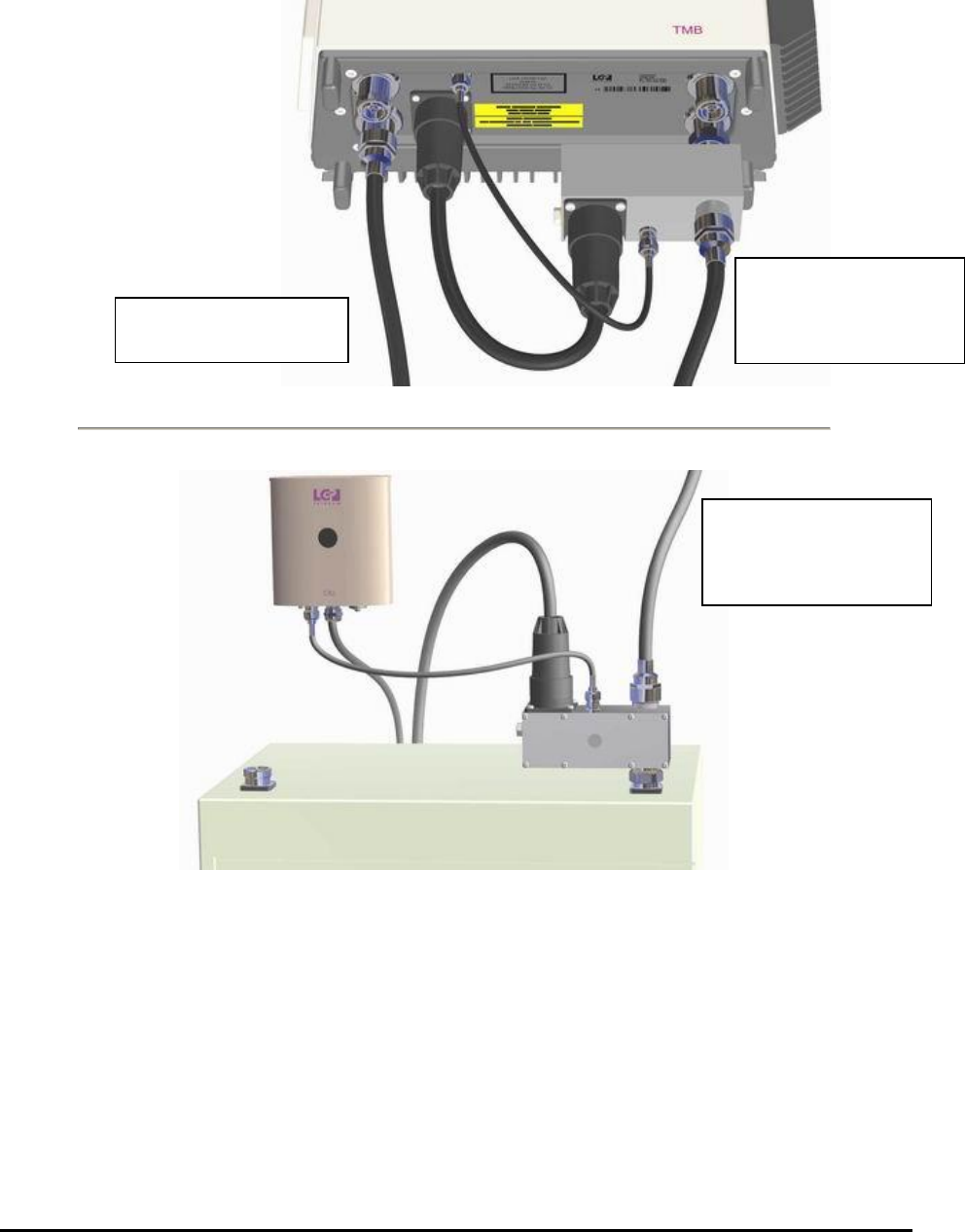
4.11 Connecting the TMB and CIU using the optional Current Injectors (CIN)
An alternative installation can be made in order to avoid the separate power
supply cable and the separate TMB-CIU cable.
This installation uses the CIN option which consists of two Current Injectors.
The first CIN (mounted on the BTS), combines the DC power and the CIU
communication and the RF onto the RF feeder. This must be the feeder that
is connected to BTS2 on the TMB.
The second CIN (mounted on the TMB, BTS2), separates the DC power and
the CIU communication onto separate cables that connect to the normal
power and CIU connectors of the TMB.
The TMB itself is the same regardless of using CIN’s, the only limitation is
that the TMB has to be a 48V DC version. The CIN’s cannot be used on AC
versions.
Note: The CIN option can only be used on DC versions,
NOT on AC versions.
Note: Make sure the BTS CIN is connected to the correct feeder
(BTS2). Connecting it to the feeder connected to BTS1 is harmful
to the CIN and the power supply, as BTS1 is DC shorted.
Figure 25a. TMB CIN overview
MMP-10065-PB1.doc © LGP Telecom AB
47 (76)
Tower Top
Base Station
Figure 25b. Installation of the CIN option.
Feeder with RX/TX2
and DC and CIU
Communication
Feeder with RX/T
X1,
no DC
Feeder with RX/TX2
and DC and CIU
Communication
MMP-10065-PB1.doc © LGP Telecom AB
48 (76)
4.12 Connecting the CIU and BTS
The CIU has to be hard wired to the BTS for alarm purposes. An RS232
connection can also be made. The CIU is supplied with a 4 meters multi wire
cable, which contains all the wired alarms.
Function Abbreviation Connection Colour
A4-2 NC Yellow
A4-1 NO Violet
Alarm output Relay # 4
A4-0 Common Brown
A3-2 NC Green
A3-1 NO White
Alarm output Relay # 3
A3-0 Common Black
A2-2 NC Pink
A2-1 NO Grey
Alarm output Relay # 2
A2-0 Common Grey/Pink
A1-2 NC Blue
A1-1 NO Red
Alarm output Relay # 1
A1-0 Common Red/Blue
Note: As the alarm relays are wired as ‘fail-safe’, NC (normally closed)
means that the contact set is closed in case of normal operation and
the relay is engaged. Power off would then result in an open circuit
which should be wired as an alarm.
MMP-10065-PB1.doc © LGP Telecom AB
49 (76)
4.12.1 Connecting the CIU/BTS alarm interface cable
The port codes are:
Alarm Connection Alarm No alarm
A1-1 to A1-0 Closed Open Alarm output # 1
A1-2 to A1-0 Open Closed
A2-1 to A2-0 Closed Open Alarm output # 2
A2-2 to A2-0 Open Closed
A3-1 to A3-0 Closed Open Alarm output # 3
A3-2 to A3-0 Open Closed
A4-1 to A4-0 Closed Open Alarm output # 4
A4-2 to A4-0 Open Closed
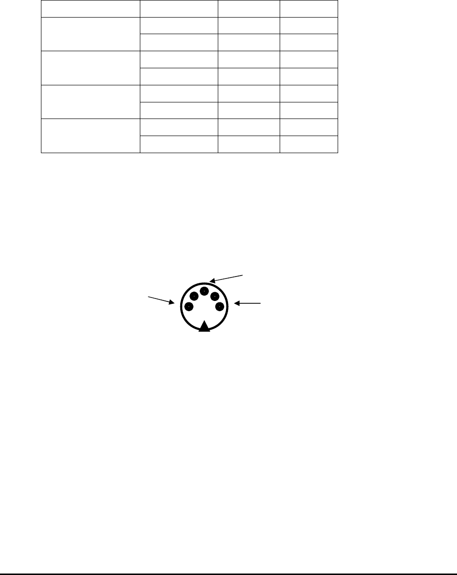
4.12.2 Connecting the CIU RS232 cable
The CIU has a serial RS232 communication interface. Total control of the
TMB system is available on this line.
The RS-232 has its own connector of the type 5S DIN (five pins), connections
are shown below. If you have an older CIU, it may be fitted with a 3 pin
connector instead.
Figure 28 Picture shows the pin configuration of the RS232 DIN
connector. Seen from outside of the CIU.
When the configuration of the TMB is completed, and you want to disconnect
the computer from the CIU you can either remove the serial cable from the
CIU, or leave the cable attached to the CIU. In case you leave the cable
attached to the CIU, make sure the PC connector is appropriately weather
protected.
Tx
Rx GND
MMP-10065-PB1.doc © LGP Telecom AB
50 (76)
4.12.3 Using the RS232 serial interface from a BTS
You can use the RS-232 serial interface to completely control a TMB. This
possibility can be used instead of the Windows program to control a TMB
from a BTS. Complete information will be available such as
• Information about S/N etc.
• Gain settings
• Performing Autocal
• Alarm settings
If you decide to use this interface, please contact LGP for a description of
valid commands to the CIU, and the CIU responses.
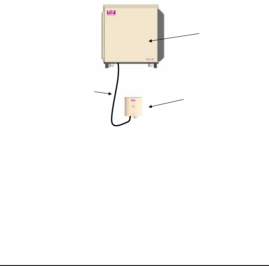
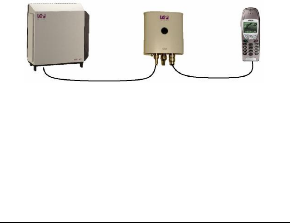
4.13 Installation of the Remote Access equipment
It is possible to substitute the RS-232 line between the CIU and the PC with a
wireless connection, using a line modem, a radio modem or a GSM modem.
This feature is called Remote Access.
Figure 29 Remote Access to TMB/CIU via GSM modem
This feature requires a different cable from the CIU that replaces the normal
PC RS-232 cable. The new cable has a male DB-9 connector that will allow
connection to most modems.
This feature has to be enabled by an option code, before it can be used. See
Chapter 6. The option code has to be purchased separately.
MMP-10065-PB1.doc © LGP Telecom AB
51 (76)
4.13.1 Supported modems
In principle, any data-enabled phone that has an RS-232 interface can be
used for this application. However, only a few modems have been tested and
can be listed as supported by LGP.
The modem or phone must be equipped with a SIM-card that is enabled for
incoming data calls. This means they have a separate GSM number for
incoming data calls.
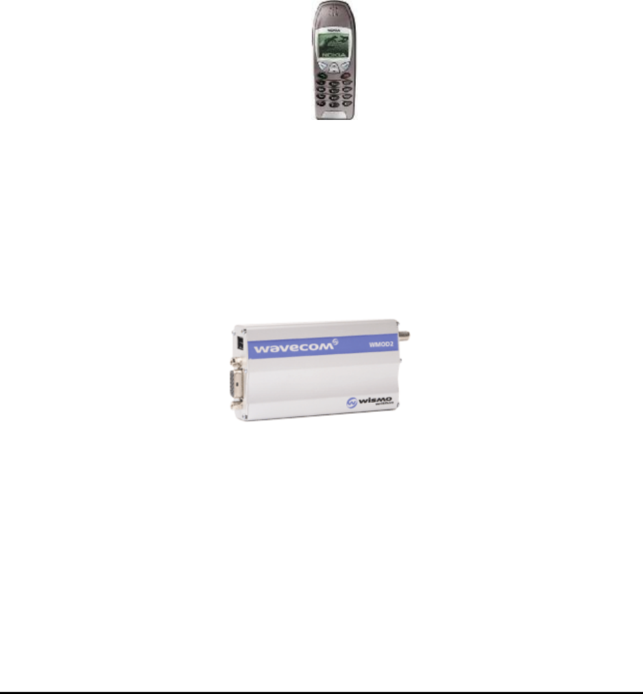
4.13.2 Nokia 6210
Nokia 6210
The Nokia 6210 has been tested, and is well suited for this application. In
addition to the phone, a Nokia data cable is necessary, type: DLR-3P. This
data-cable converts the proprietary Nokia connector at the bottom of the
handset to a normal DB-9 RS-232 connector (female). This connector will fit
to the data cable described in section 4.13.
4.13.3 Wavecom WMOD2
Wavecom WMOD2
The Wavecom WMOD2 has been tested, and is well suited for this
application. In addition to the modem, an external antenna and a Wavecom
data cable is necessary. This data-cable converts the DB-15 (VGA type, 3
rows) connector to a normal DB-9 RS-232 connector (female). This
connector will fit to the data cable described in section 4.13.
The use of the Wavecom modem also requires a small antenna, and a power
supply.

MMP-10065-PB1.doc © LGP Telecom AB
52 (76)
4.13.4 Remote PC with modem
When using the remote access feature, there must also be a modem at the
other end of the line, to be able to dial the TMB’s.
This can be any normal modem (Data rate >=9600 baud) for use with a PC
and compatible with Microsoft Windows 98/NT/2000. Note that for use with
the Remote Access option, Windows 95 is NOT supported.
The use of the Remote Access software is described in chapter 6.
4.13.5 Additional installation information for Remote Access
When setting up the Remote Access option, it must always be verified that
the TMB is functioning properly and installed correctly before attempting to
make a remote connection. This is done by using a PC and the normal
RS-232 cable.
When the TMB is installed properly, simply remove the RS-232 cable
between the CIU and the PC, and replace it with the new cable connected to
the modem.
Turn the modem on and access a GSM network.
Always leave the power supply or charger connected to the modem or phone
to ensure the battery in the phone does not get discharged.
Now try to dial the TMB using a PC with a modem using the Remote Access
version of the PC software (TMB manager version X1L or later).
For the communication on the RS-232 line, the CIU is using a proprietary
own protocol. If the TMB is being dialled using a text-based modem program
(such as Hyperterminal or ProComm), no information of the TMB can be
extracted, and no setting can be made. The caller must use the program
designed for the TMB.

MMP-10065-PB1.doc © LGP Telecom AB
53 (76)
5 Commissioning
5.1 Prerequisites
Before the TMB can be commissioned, it must be installed correctly, as
described in the “Installation” part of this document.
5.2 The commissioning procedure
The LGP TMBs have been carefully designed, manufactured and extensively
tested. The commissioning procedure is therefore relatively easy, and can be
outlined as follows:
1. Verify that the TMB is correctly and securely installed (see
“Installation” section of the manual if needed).
2. Verify that RF feeders, CIU interconnection cable, grounding wire
and power supply cables are attached correctly.
3. Check that the power supply voltage is according to the TMB
configuration (230 / 115 VAC or 48 VDC).
4. Switch on AC (or DC) power to the TMB unit.
5. Wait a few seconds for the TMB Self Test to finish.
6. Check that the green LED indicator on the CIU is on.
7. Boot your portable PC and open the LGP TMB application.
8. Click on the “Status” menu.
9. Check alarms.
10. Set the desired parameters. Use the Autocal feature to align power
levels.
11. The PC does not have to be connected to the CIU at all times.
When the configuration is completed, you can close the application
and remove the PC.
The commissioning procedure is finished. Consult the “Configuration &
Operation” chapter of this manual for further guidance.
Should there be any problems, please consult the “Trouble Shooting” chapter
of this manual.

MMP-10065-PB1.doc © LGP Telecom AB
54 (76)
6 Configuration & Operation
The main operation and configuration interface is the RS232. The same
control can be obtained using the infrared Laptop interface on the CIU.
This chapter outlines the O&M options in detail.
6.1 Introduction
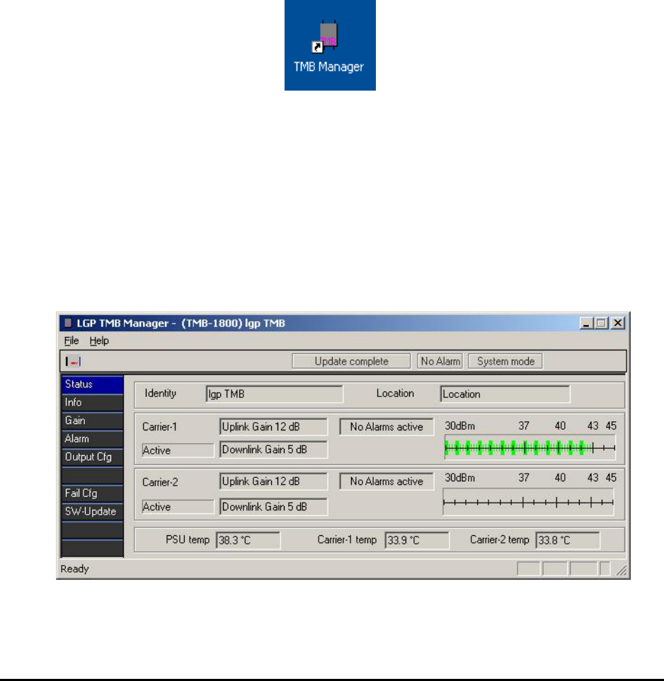
To simplify the configuration and control of the TMB, LGP has chosen a
straightforward interface using a PC program called TMB Manager. The TMB
Manager has one Status information window, which contains the current
setting and several sub-menu configuration windows for each particular
operation.
6.2 Installing TMB Manager
The TMB Manager software is compatible with the following versions of
Microsoft Windows:
• Windows 95 / Windows 98 / Windows 2000 / Windows NT4 /
Windows XP
However, for the remote access version, Windows 95 is no longer supported.
6.2.1 Prerequisites
Before you proceed, make sure that the TMB has been commissioned
correctly, as described in the “Commissioning” part of this documentation.
6.3 Connecting to the TMB
There are three ways of connecting a computer to the TMB. Choose
between:
- Locally, making a direct serial connection to the CIU via the RS232
interface.
- Locally, making an infrared interface connection to the CIU.
- Remotely, using the Remote Access feature and a GSM modem
In all cases the graphical user interface/presentation will be the same.
The infrared and the serial connections operate in parallel. However, a
detection of interface will take place automatically and communication will be
routed to this interface and locked to it as long as there is active
communication.

MMP-10065-PB1.doc © LGP Telecom AB
55 (76)
6.3.1 RS232 connection
The CIU has a serial RS232 communication interface built in. Total control of
the TMB system is available on this line. The RS232 interface functions in
parallel to the infrared IrDa interface. The CIU will automatically scan the
COM ports (infrared or RS232) in a continuous manner.
See chapter “Installation” for interconnection details.
6.3.2 About the wire-less infrared (IrDa) interface
The infrared interface complies to the international IrDa standard:
This interface type avoid using wired connection and hence complications
with connectors, adapters, protection, etc.
Stand within one (1) meter from the CIU and point the infrared sensor on the
portable Laptop/Palmtop towards the infrared sensor on the CIU, when
communicating with the TMB. Note that a green LED will flash inside the
window on the CIU and a small transmission indicator will be activated on the
PC screen.
In very clear and strong sun light problems can occur. In case of problems try
to create shadow on the infrared sensors.
The performance of the Infrared connection is limited by the IrDa standard
and by the performance of the Infrared device in the PC you are using. If
Infrared performance is not satisfactory, please revert to using the RS-232
interface.
6.4 The TMB Manager (PC program)
6.4.1 TMB Manager program versions
The TMB Manager program is compatible with Microsoft Windows
operating system.
The screenshots shown in this manual is valid for the following version of the
program:
TMB-Manager.exe 2002-06-28
Earlier versions of the program has been called ‘PCOIU’. The funcionality
remains the same.
6.4.2 Computer system requirements
The TMB Manager program is supplied with the TMB. To run it, you will need:
• A 486DX computer or better, running Windows 95/98/NT/2000/XP
MMP-10065-PB1.doc © LGP Telecom AB
56 (76)
• An SVGA monitor
• One megabyte of free hard disk space. The TMB Manager can also
run from a diskette.
6.4.3 Installing the TMB Manager on your PC
The TMB Manager consists of a single executable file, and there is therefore
no installation procedure.
Copy the program (File: TMB Manager.exe) to the preferred directory on your
PC.
Just double-click the TMB Manager icon to start the program
In case you need to install a new version of the program (distribution file)
which you have received from LGP, then copy the distribution file to the same
directory as the old program and run the TMB Manager again.
6.5 The TMB Manager menus
Below you will find a description of the various menus.
The main window is showing the possible sub-menus. Click on a sub-menu
icon in the left of the picture to access the menu.
MMP-10065-PB1.doc © LGP Telecom AB
57 (76)
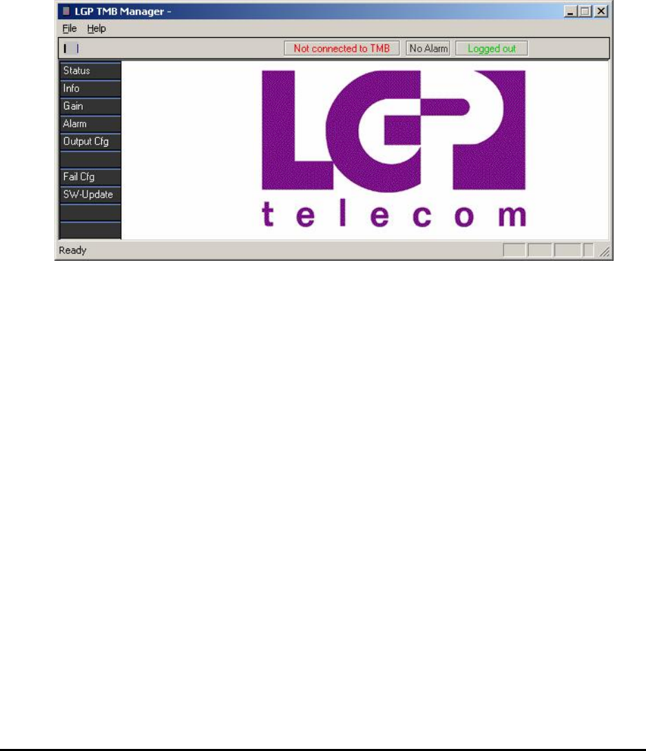
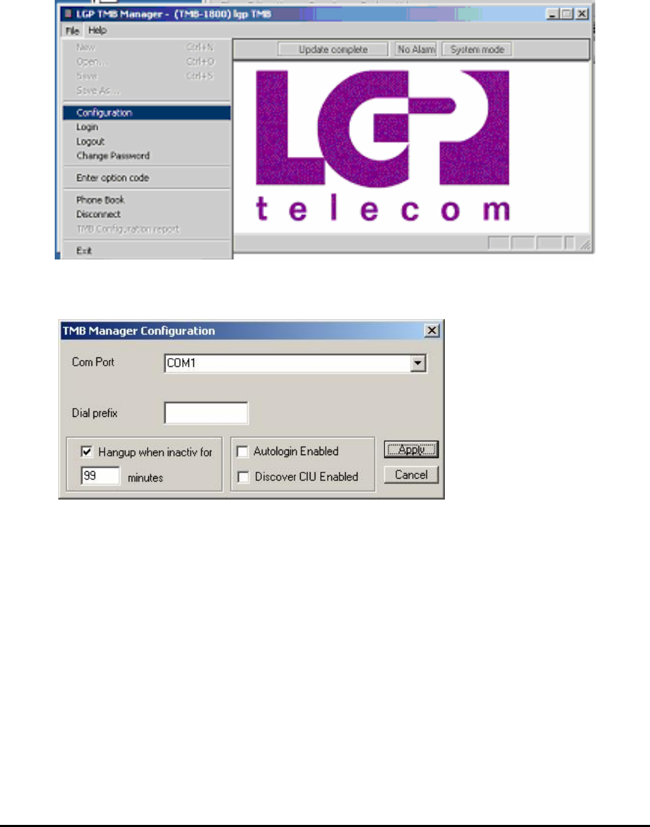
6.5.1 Communication port configuration
In case there is no communication to the CIU, “Not connected to TMB” will be
displayed in the top status bar.
No communication can be caused by:
• The TMB is switched off
• The CIU is not connected to the TMB
• The CIU is not connected to the PC
• The COM port is occupied by an other program. Close the program
and re-start the TMB Manager
• A wrong COM port has been selected
MMP-10065-PB1.doc © LGP Telecom AB
58 (76)
To configure the COM port, enter the File menu and click on “Configuration”
Select the appropriate COM port
Refer to the user manual of the PC to select the appropriate communication
port as this depends on the hardware configuration of the PC. This
particularly applies to the location of the IrDa port.
MMP-10065-PB1.doc © LGP Telecom AB
59 (76)
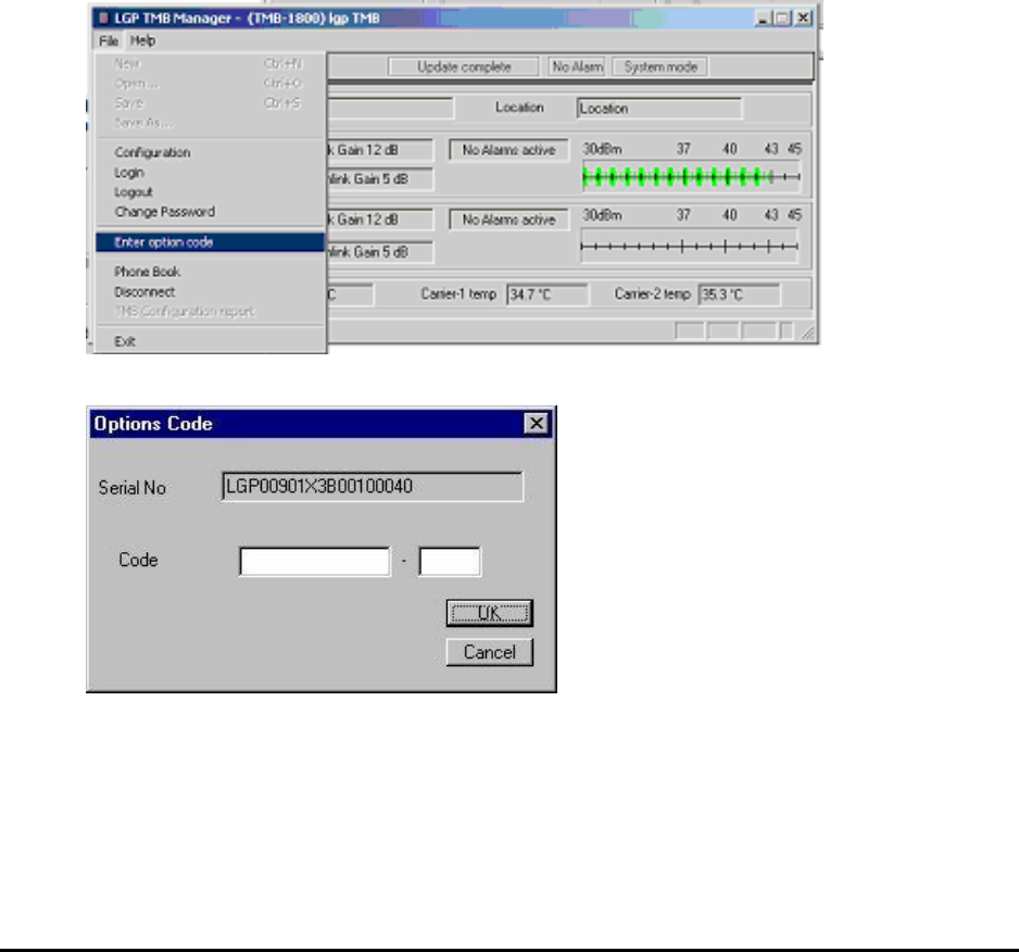
6.5.2 Access TMB options using a code
Some features of the TMB are optional. These features require a code, in
order to make them available. The codes can be purchased with LGP
Telecom Customer Service.
Currently, two options are available:
- Antenna Monitor (VSWR alarm)
- Remote Access
LGP Telecom Customer Service needs the serial numbers of the TMB and
will via this number provide the unique password code for the product option.
The serial number needed is the exact text string listed in the ‘Serial No’ field
in the ‘Info’ menu.
Enter the code which you have received and click OK. The option is now
enabled. This can be verified in the Help-About window.
MMP-10065-PB1.doc © LGP Telecom AB
60 (76)
Note: The code for the Antenna Monitoring function (VSWR) is unique for
each individual TMB and is derived from the product serial number.
Note: If Antenna Monitor option isn’t accessed, the “VSWR-alarm” menu
and LED is not available.
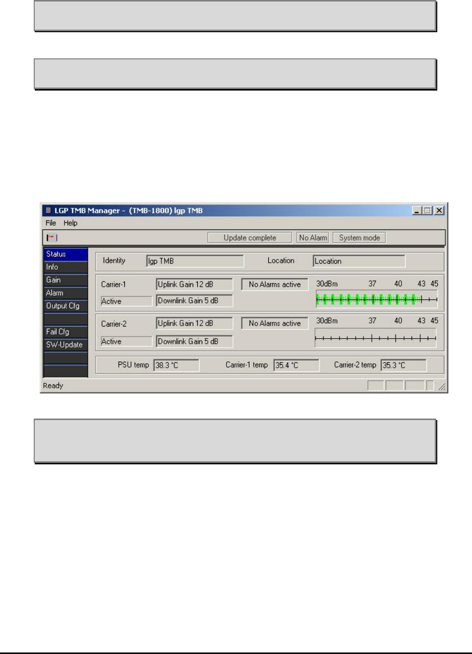
6.5.3 Status menu
A pure information menu. The current configuration status is shown along
with identity and location information.
Note: The power indicators shown for each channel are designed to help
you visualise that there is output power from the TMB. It is by no
means an exact measurement.
6.5.4 Information menu
The TMB Info menu contains various information about the TMB and enables
entering of user information as well.
MMP-10065-PB1.doc © LGP Telecom AB
61 (76)
“Identity” and “Location” are text strings that can be entered by the user. The
lower fields are information about the product, which can not be modified.
The software version is updated when a new software version is installed.
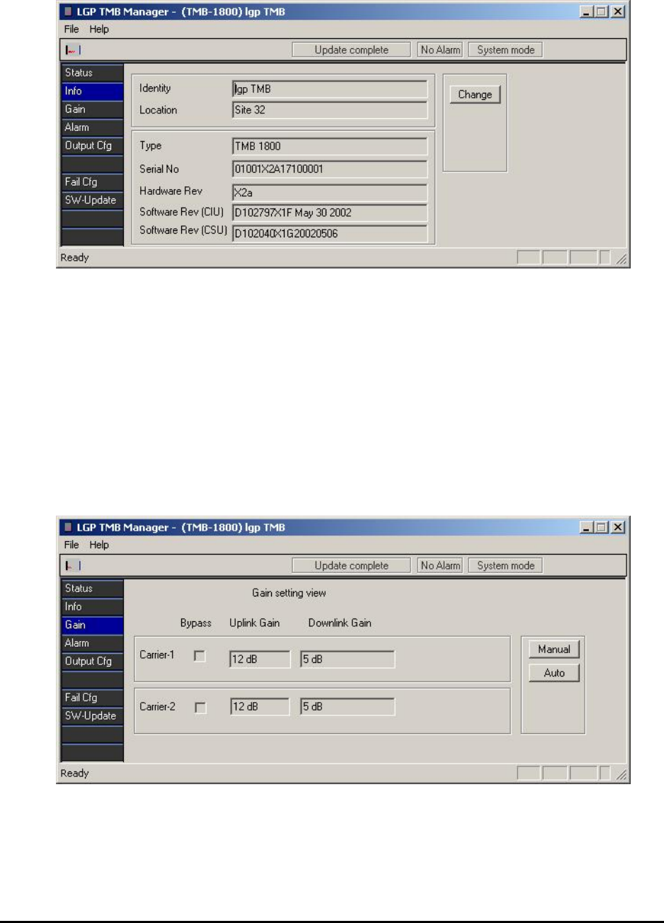
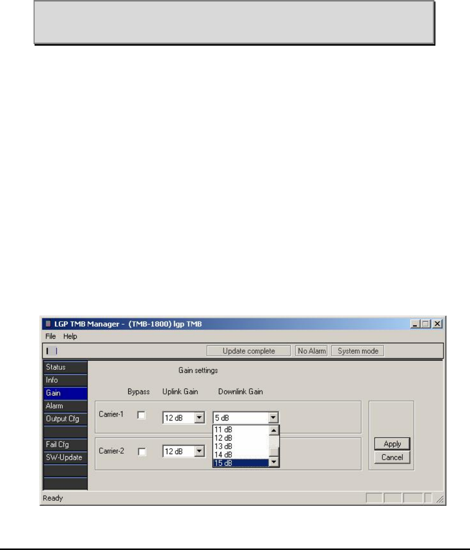
6.5.5 Gain setting menu
In this sub-menu you can enable or disable the amplifiers and set the gain of
all four amplifiers.
The first screen picture is only showing the status of the gain setting.
The gain setting of the downlink amplifier (HPA) can either be done manually
or automatically. The uplink amplifier (LNA) shall in all cases be set manually.
MMP-10065-PB1.doc © LGP Telecom AB
62 (76)
Manual setting is used where the cable path loss from the BTS to the TMB is
known, or if equipment is available to verify the output power of the TMB.
Also, if data already exists from field measurements indicating a certain link
balance problem of x dB, then the manual gain setting can be used with
advantage.
The automatic setting is used where the cable path loss is unknown or
unaccurate and only a certain power to the antenna is desired.
Note: Due to the tolerances of gain on the TMB, and tolerances of output
power from the BTS, the automatic gain setting is very useful to
ensure the correct output power.
Manual Setting
A click on the Manual button will allow manual gain setting of four amplifiers
individually. Also, it is possible to put a carrier in bypass mode.
If bypass is chosen, both up- and down-link will be bypassed. Please note
that in the event of a failure, the bypass switches do function individually, so
only the faulty link is bypassed.
Click on the scroll down arrow of each gain setting window and pick the
desired gain.
All gain settings can be different as the amplifiers work completely
independent.
Having entered the desired gain values click OK and the new setting will be
applied, or click Cancel if you do not want to change the current setting.
MMP-10065-PB1.doc © LGP Telecom AB
63 (76)
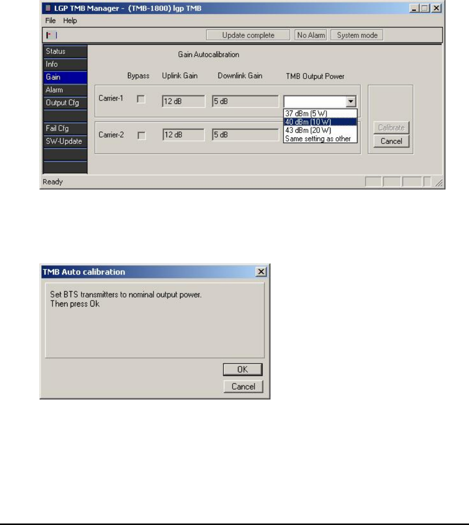
Auto Setting
Automatic calibration of the gain is done by clicking on the Auto button. The
screen picture will change slightly. The carriers can still be enabled or
disabled and the Uplink (LNA) gain can be set. However, the Downlink (HPA)
power level must now be set instead of the HPA gain. The indicated power
level is pr. carrier and valid at the TMB output antenna connector.
Having entered the desired Uplink gain and Downlink power level, click
Calibrate.
The TMB will now require that the BTS power is set at its nominal power
level. Using this power level as input reference level to the TMB, the
Downlink gain resulting in the desired output power can be calculated by the
TMB.
Adjust the BTS to the desired nominal power and click OK.
MMP-10065-PB1.doc © LGP Telecom AB
64 (76)
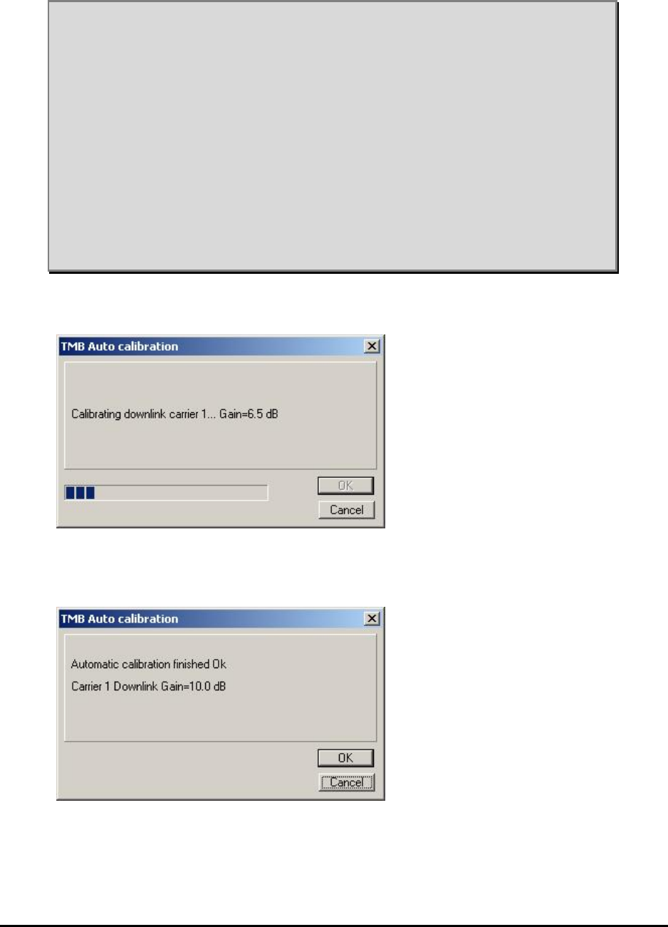
Note 1: It is preferred to run the TMB at high gain and the BTS at low power
due to feeder cable loss.
Note 2: Running the BTS at reduced power and the TMB at full power will
add some “safety” to the site. In case the downlink amplifier (HPA) in
the TMB fails for some reason and by-pass mode is activated, then
the BTS can use this alarm signal to increase the BTS output power
and thereby compensate for the lost output power.
Note 3: Having only one time slot active during calibration is sufficient.
Note 4: Having completed the auto calibration, the gain will remain fixed.
Increasing the BTS output power later on without re-calibration may
create intermodulation products in the TMB and saturate the
amplifiers, but only if it is already running at maximum power (+43
dBm or 20 watt)
During the calibration a progress indicator will be displayed.
After auto calibration, the TMB will show the calculated gain setting values.
Click OK to accept them or cancel to retain the previous settings.
The gain setting window will be updated with the predicted values. Those
gain values will be fixed and remain until a new setting is made.
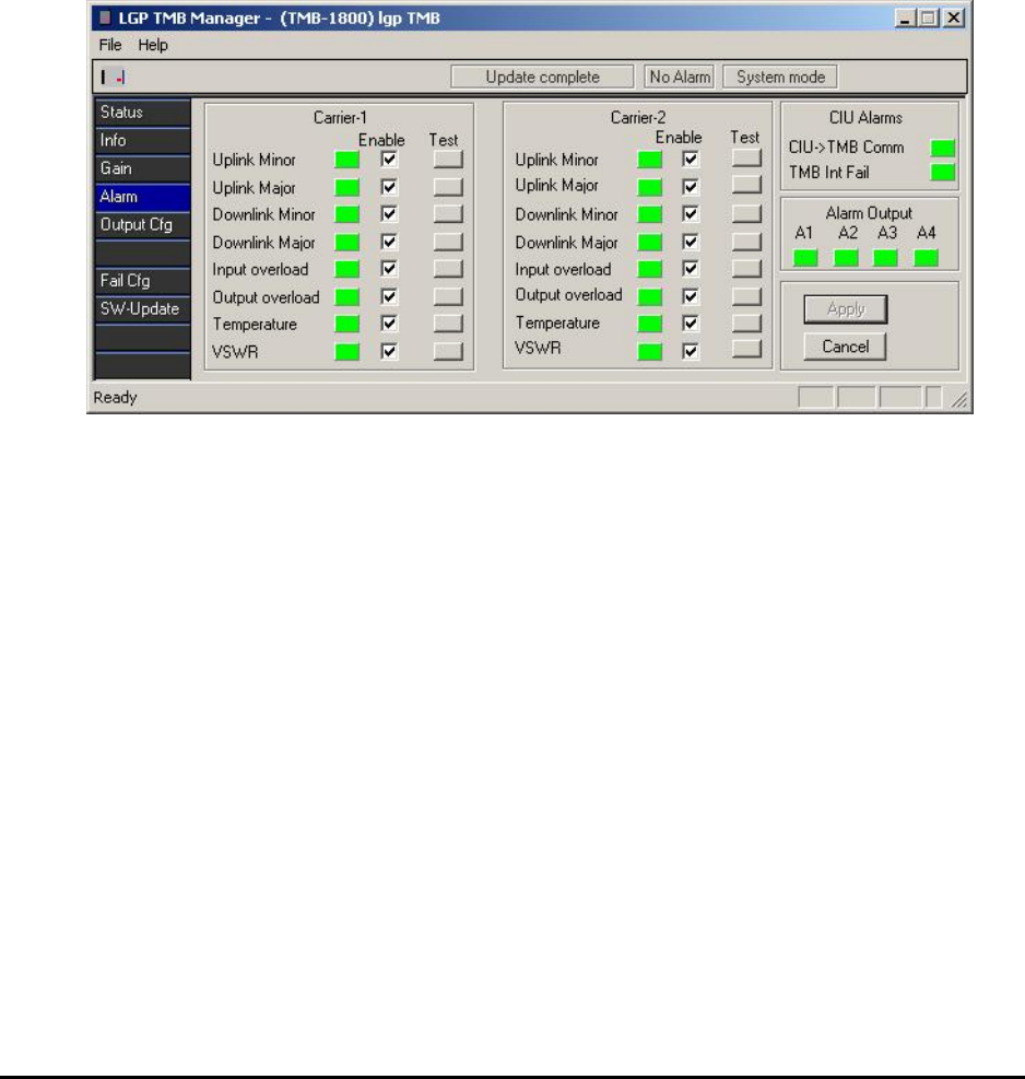
MMP-10065-PB1.doc © LGP Telecom AB
65 (76)
6.5.6 Alarm setting menu
In this sub-menu you can enable or disable the various alarms.
It is possible to monitor all alarm for each carrier/link independently.
However, there are 4 relay alarm contacts for the TMB. The relay contacts
are normally open (NO) or normally closed (NC), making a total of 12 wires
(four times NO-wires, four times NC-wires and four times common wires). In
case the RS232 communication and the TMB Manager is used, all alarms
can be monitored.
The software LED indicators on the screen will be green or red or grey
depending on the alarm status.
Put a checkmark for the types of alarms that you want to monitor.
Your choices will only be activated after you hit Apply.
See also “Alarm functions” in the “Functional Description” chapter.
The “Test” buttons can be used to simulate an alarm. Click a button and the
corresponding alarm will be activated for 10 seconds. The corresponding
relay will also be activated, if configured. In this way you can check that the
alarms are correctly connected to the BTS interface.
The “CIU Alarm” is an indicator monitoring the modem communication
between the CIU and the TMB. A failure in the communication will change the
indicator from green to red.
The “Alarm Output” indicates the status of the four relays. If an alarm is active
and routed to a relay output (see next paragraph), you will see an indicator of
the given alarm being red as well as the corresponding relay.
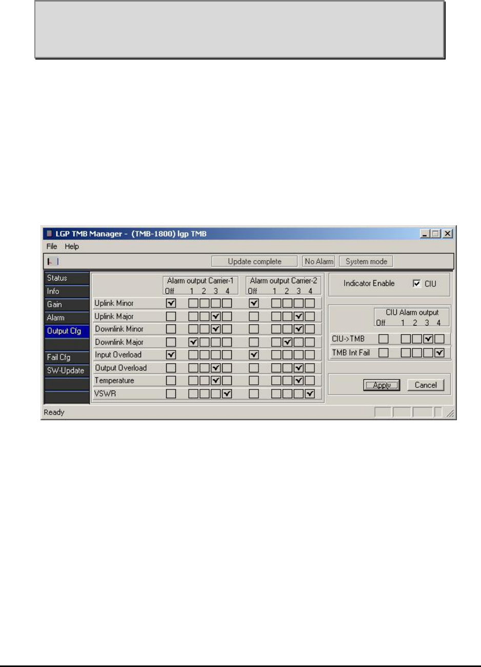
MMP-10065-PB1.doc © LGP Telecom AB
66 (76)
Note: The Antenna Monitoring function (VSWR) is a special product option.
The menu is accessed as described in above chapter “Access
Antenna Monitor (VSWR)”. If Antenna Monitor option isn’t accessed,
the “VSWR” menu and LED is not visible.
6.5.7 Alarm output configuration menu
In this sub-menu you can configure the wired relay contacts in the CIU. There
is a total of 4 relay contacts (open or closed) for the TMB.
More alarms can be routed to the same relay contact giving an “OR” function.
The choice of which alarms to monitor is entirely free, and it is not required
that the same alarms are monitored in the two links.
Put a checkmark for the types of alarms that you want on the various outputs.
The LED’s on the CIU can be enabled/disabled in this menu as well, in case
you do not want them visible. However, the green indicator will always be
visible whilst communication to the PC.
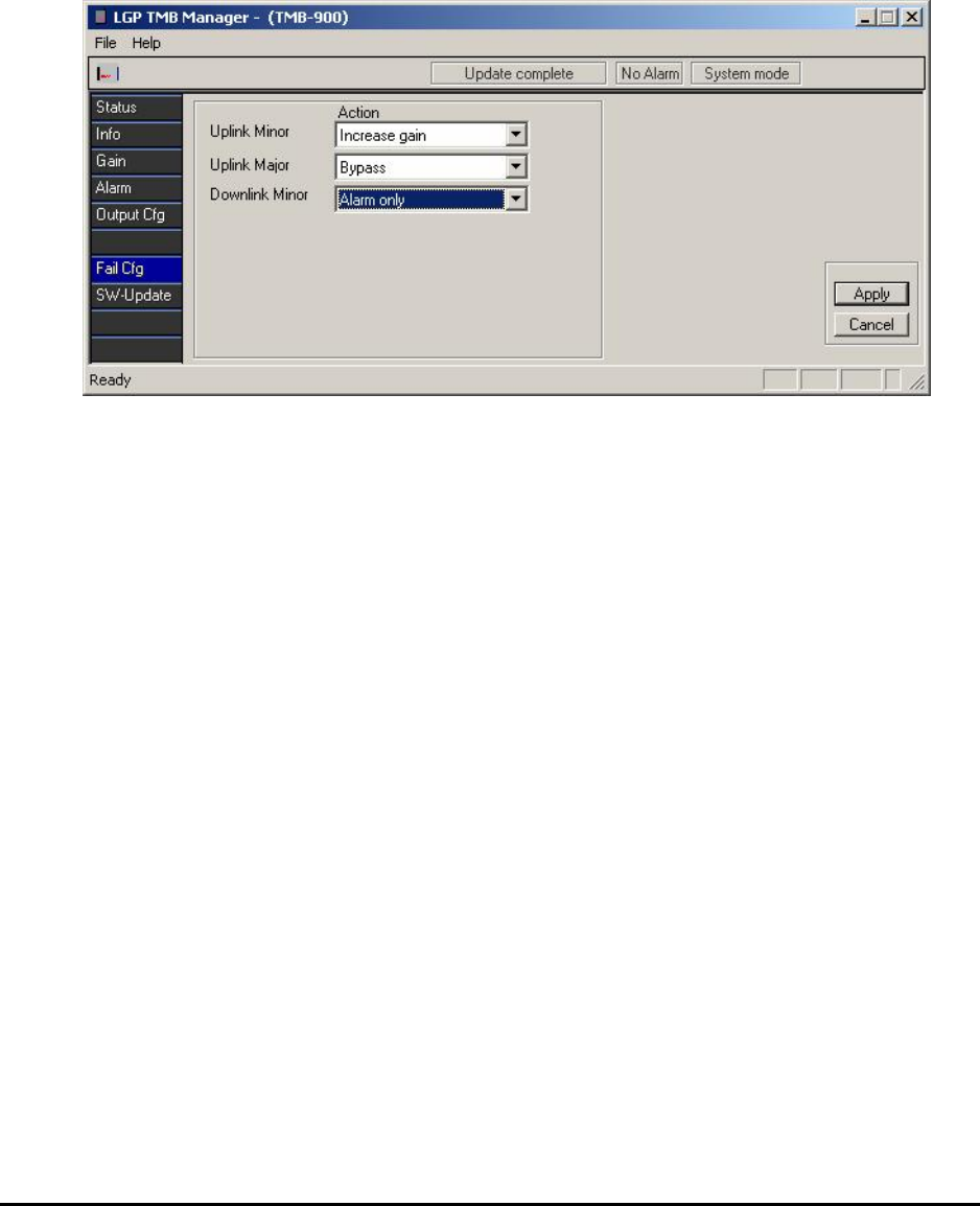
MMP-10065-PB1.doc © LGP Telecom AB
67 (76)
6.5.8 Failure Configuration menu
In this sub-menu it is decided which action the TMB shall take upon a failure.
For TMB-900, the choices are:
• Uplink Minor: Alarm only or Increase gain (default is Alarm only)
• Uplink Major: Alarm only or by-pass (default is Alarm only)
• Downlink Minor: Alarm only or by-pass (default is Alarm only)
For TMB-1800, there are no choices and the settings are:
• Uplink Minor: Increase gain
• Uplink Major: By-pass
• Downlink Minor: Alarm only
For each amplifier (uplink and downlink) the actual choice is set simply by
scrolling down the window and selecting the desired action.
The By-pass mode is realised as a switch, bypassing the amplifiers only and
not the duplex filters. Measuring the antenna return loss (VSWR) via the RF
feeder cable and through the TMB in By-pass mode is not recommended.
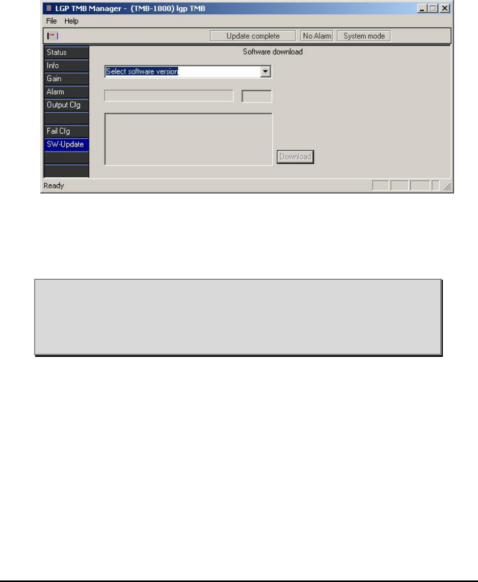
MMP-10065-PB1.doc © LGP Telecom AB
68 (76)
6.5.9 CIU Software updating menu
The main software controlling the TMB behaviour resides in the CIU. This is
not the same as the PC program. The software in the CIU can be
changed/updated via a simple download function.
In the software menu you will see the different software versions which
currently are stored locally in the PC. The CIU software files (type *.A90)
need to be in the same directory as the TMB Manager. To make an update,
select the version to download and click the download button.
Note 1: Download of new CIU software will not interfere with the operation of
the TMB, but the alarm relay contact outputs to the BTS will be
turned off (if active) during download.’
Note 2: The current setting will be maintained during software updating, i.e.
no need to set gain values again.
A typical download screen will be seen while the downloading is proceeding.
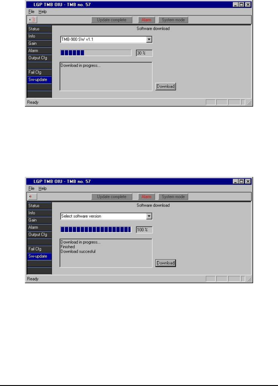
MMP-10065-PB1.doc © LGP Telecom AB
69 (76)
When the download is complete, the result (failure or success) is shown on
the download menu.
In case of a failure (most likely if IrDa is used due to interference) the
software download has to be repeated until it is successful. This is necessary
because of the deletion of the previous software in the CIU.
A normal software download takes approximately 20 minutes.
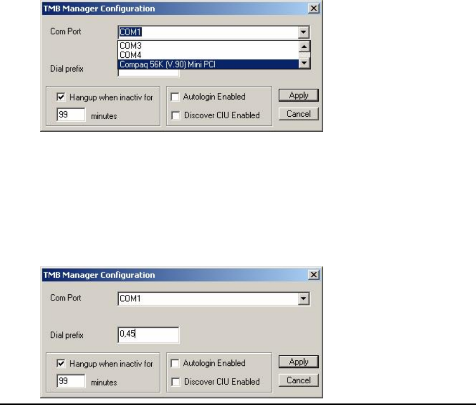
MMP-10065-PB1.doc © LGP Telecom AB
70 (76)
6.6 Remote Access option to TMB Manager
If you have purchased the Remote Access option to the TMB, you can dial
the TMB using the TMB Manager. This is described in this paragraph.
6.6.1 Modem installation
The computer being used for remote access needs to have a modem
installed. The modem should be installed using normal procedures for
installing hardware under Windows. Please consult the manual for your
modem.
After the modem has been installed properly, it should be visible under the
Windows Control Panel.
The modem can now be selected under the configuration menu in the TMB
Manager. If a COM port is chosen in the configuration menu, the TMB
Manager will function normally as previously described. If a modem is chosen
instead, the remote access features will appear.
For the selected COM port, it is also possible to enter a dial prefix. The dial
prefix is added in front of the telephone number selected in the phone book.
The example below shows:
• 0: to get external line
• , (comma): pause
• 45: country code for Denmark
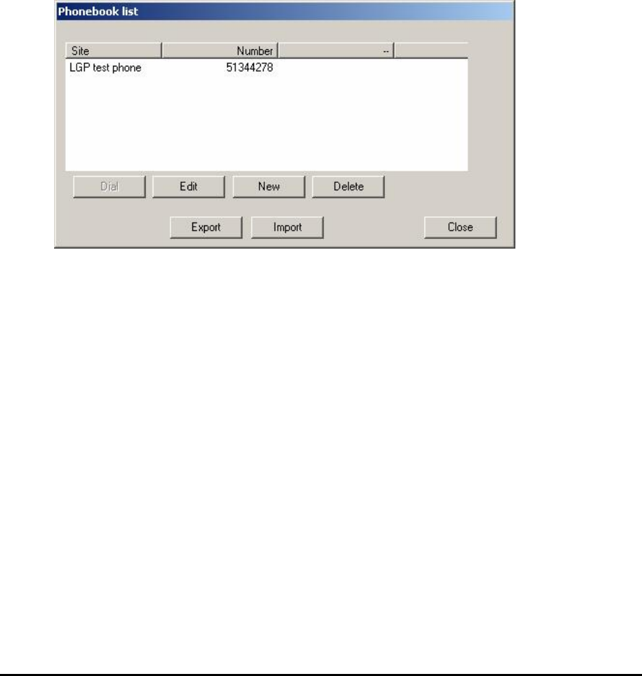
MMP-10065-PB1.doc © LGP Telecom AB
71 (76)
6.6.2 Phone book (list of TMB’s)
Here you enter the phone numbers for your pool of TMB’s. Each one can be
given a name, i.e. “Village X, Sector A”.
The contents of the Phone book is stored in the Windows Registry, and will
automatically be saved. If you need to transfer the phone book to another
PC, use the “Export” and “Import” buttons. The contents of the phone book
will then be converted to a comma-separated file (phonebook.txt), that you
can transfer on a floppy disk or by E-mail.
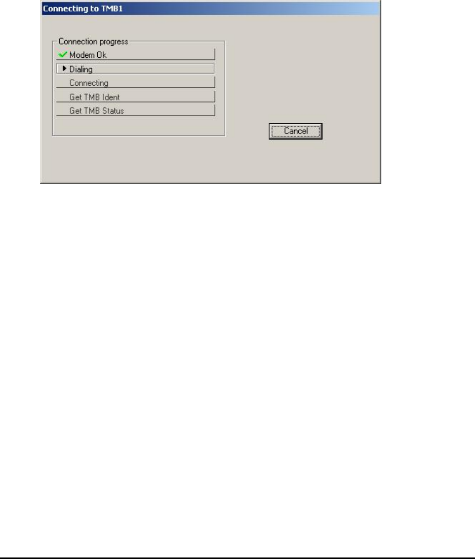
MMP-10065-PB1.doc © LGP Telecom AB
72 (76)
6.6.3 Dial TMB
After you have selected a TMB from the phone book, press the Dial button,
and the number will be dialed using the installed modem.
The Dial screen will show the progress of your call. This is helpful, in case
something is not connected right.
After the connection is established, the TMB Manager will look the same as it
does when connecting directly to a CIU using the RS-232 cable. The menus
described in the previous sections are therefore still valid. Please refer to
these sections for monitoring a TMB.
When you are done monitoring the first TMB, you can choose to Disconnect
from the File menu. After that another TMB can be called.
If you choose to close the TMB Manager, the present call will also be
terminated.
Note that the status bar on top now has an indicator for Online/Offline.
6.6.4 Troubleshooting Remote Access problems
Using Remote Access, there are more possibilities of errors when connecting
to a TMB. To avoid these problems, always:
1) Make sure the CIU communicates on the RS-232 with a PC before
attempting to use Remote Access.
2) Make sure the data SIM card works by dialling from a modem before
installation.
3) Make sure the TMB being dialled is enabled for Remote Access (requires
option code from LGP)
When these things are in order, the problems can be located using the status
information in the dial window.

MMP-10065-PB1.doc © LGP Telecom AB
73 (76)
There are several possibilities:
1) If the modem is installed properly, a “Modem OK” message should appear
in green color quite quickly. If this does not happen, check your modem
installation again.
2) If the modem is unable to get a dial tone, a “Dial tone Fail” message will
appear. If this is the case, check your cable going from the modem to the
phone plug in the wall.
3) If the program fails to complete the call to the listed number, a ……. Will
appear. If this is the case, check the number again. Also make sure that
the dial prefix has been set properly in the configuration menu. (If you
need to dial 0 to get an outside line, the proper setting is “0,”).
4) If the call is completed, but there is apparently no TMB/CIU in the other
end, check the cable between the CIU and the remote modem.
MMP-10065-PB1.doc © LGP Telecom AB
74 (76)
7 Maintenance
The TMB system is in principle maintenance free.
7.1 Maintaining the TMB
The unit does not contain any fans or other mechanical moving parts.
The unit contains a fuse (AC versions only), located at the bottom plate of the
TMB. The unit shall in addition always be protected by a fuse from the main
power supply.
Fuse type in the TMB: 5mm 6.3 A slow (230 VAC)
The two heat sinks on the TMB unit must be kept free from dust and mud.
Under normal weather conditions there should not be any need for cleaning
the TMB. Mud and dust will under normal conditions be cleaned by natural
rain and wind.
7.2 Replacing the TMB
If the TMB has to be replaced, the following procedure is recommended.
1 Switch off the AC or DC supply
2 Disconnect the power plug
3 Switch off the RF carriers from the BTS
4 Disconnect the RF feeder cables and the CIU cable
5 Disconnect the Earth cable
6 Loosen the four screws at the back of the TMB. The screws are “non
drop” types
7 Lift the TMB off the mounting plate. If the TMB handle is available attach
it and lift the TMB using the handle.
Note: Be sure to attach the handle correctly, which means that it is securely
locked and hereby prevents the TMB from dropping off the handle.
If the TMB is not replaced immediately by another TMB unit, make sure to
weather protect the open-ended cables.

MMP-10065-PB1.doc © LGP Telecom AB
75 (76)
8 Troubleshooting
Note: Service and repair of internal parts of the TMB must only be
carried out by qualified, authorised and trained LGP personnel.
Exceptions are strictly limited to service and repair that can be
carried out on the outside parts of the TMB.
The table below summarises the main trouble shooting measures. In some
cases you must send the TMB for factory service, but below table might
assist problem solving and trouble diagnostics.
Error Possible cause Suggested action
Power indicator
LED (green) in
CIU is off
- No main voltage
- No CIU/TMB connection
- LED disabled via
software in the setup
menu
- Fuse is faulty (AC only)
- Check the incoming AC or
DC voltage
- Check the TNC connector
on the CIU and the
CIU/TMB communication
cable
- Enter the setup menu and
enable the LED’s
- Check fuse
Power indicator
LED (green) is
flashing
- The CIU is in communi-
cation mode and being
addressed
- No action. Normal mode
indicating “busy line” during
PC / CIU communication.
No RF or too low
output power - No input power
- Carrier turned off
- Feeder cables wrongly
connected.
- No main power supply to
the TMB
- Check the RF power out of
the BTS
- Check in the Gain Setting
menu to see if the carriers
are disabled.
- Check that BTS input of the
TMB is connected to the
feeders going to the BTS
- Check the main power
source

MMP-10065-PB1.doc © LGP Telecom AB
76 (76)
No screen picture
on PC - PC not booted correctly
- LGP software not in-
stalled
- Re-boot PC
- Re-load LGP software
No communi-
cation to the TMB
from the PC
- Infrared interfaces on
TMB and PC not aligned
- RS232 cable not
connected
- Wrong COM port
selected on PC
- Repoint the infrared
interfaces and lower
distance to max. 1 mtr.
- Look for flashing green LED
in the CIU and “signal
indicator” on the PC screen,
all indicating that
communication is ongoing.
- Make sure the correct COM
port is used on the PC
- Try RS232 instead of IrDa
Low downlink
gain or output
overload alarm
- Check that you are not
over loading the TMB. - Adjust down the transmitter
power to a proper level. As
low as possible is normally
preferable.