Powerwave Technologies LNKA100 LINKNET RF BROADBAND AMPLIFIER MODULE User Manual Kaval OFR 800
Powerwave Technologies Inc. LINKNET RF BROADBAND AMPLIFIER MODULE Kaval OFR 800
Contents
- 1. USERS MANUAL
- 2. BROCHURE
USERS MANUAL
LinkNet™
LinkNet™LinkNet™
LinkNet™
LNKA100, LNKA400, LNKA800
LNKA100, LNKA400, LNKA800LNKA100, LNKA400, LNKA800
LNKA100, LNKA400, LNKA800
RF BROADBAND
RF BROADBANDRF BROADBAND
RF BROADBAND
AMPLIFIER MODULES
AMPLIFIER MODULESAMPLIFIER MODULES
AMPLIFIER MODULES
USER MANUAL
USER MANUALUSER MANUAL
USER MANUAL
INSTALLATION, OPERATION
INSTALLATION, OPERATIONINSTALLATION, OPERATION
INSTALLATION, OPERATION
AND MAINTENANCE
AND MAINTENANCEAND MAINTENANCE
AND MAINTENANCE
KAVAL WIRELESS TECHNOLOGIES
60 Gough Road
Markham, Ontario, L3R 8X7
Telephone: (888) 86-KAVAL
Web: www.kaval.com
E-mail: info@kaval.com
Document #DCM000000054, Rev.12
December 15, 2003

LinkNet™ LNKA RF MODULES z USER MANUAL DCM000000054
Printed: 2003-12-15 10:19:33
Revision Date: 12/15/03: ii
P
PP
P
P
PP
PR
RR
R
R
RR
RO
OO
O
O
OO
OP
PP
P
P
PP
PR
RR
R
R
RR
RI
II
I
I
II
IE
EE
E
E
EE
ET
TT
T
T
TT
TA
AA
A
A
AA
AR
RR
R
R
RR
RY
YY
Y
Y
YY
Y
S
SS
S
S
SS
ST
TT
T
T
TT
TA
AA
A
A
AA
AT
TT
T
T
TT
TE
EE
E
E
EE
EM
MM
M
M
MM
ME
EE
E
E
EE
EN
NN
N
N
NN
NT
TT
T
T
TT
T
© 2000 KAVAL WIRELESS TECHNOLOGIES All rights reserved.
No part of this publication, or any software included with it may be reproduced, stored in a retrieval system,
or transmitted in any form or by any means, including photocopying, electronic, mechanical, recording or
otherwise, without the prior written permission of the copyright holder.
This document contains proprietary information of KAVAL WIRELESS TECHNOLOGIES The contents are
confidential and any disclosure to persons other than the officers, employees, agents or subcontractors of
the owner or licensee of this document, without the prior written consent of KAVAL WIRELESS
TECHNOLOGIES, is strictly prohibited.
KAVAL WIRELESS TECHNOLOGIES provides this document as is, without any warranty of any kind either
expressed or implied including, but not limited to, the implied warranties of merchantability and fitness of a
particular purpose. KAVAL WIRELESS TECHNOLOGIES may make changes or improvements in the
equipment, software, or specifications described in this document at any time and without notice. These
changes will be incorporated in new releases of this document.
This document may contain technical inaccuracies or typographical errors. KAVAL WIRELESS
TECHNOLOGIES waives responsibility for any labour, materials, or costs incurred by any person or party as
a result of using this document. KAVAL WIRELESS TECHNOLOGIES, and any of its affiliates shall not be
liable for any damages (including, but not limited to, consequential, indirect or incidental, special damages or
loss of profits or date) even if they were foreseeable and KAVAL WIRELESS TECHNOLOGIES has been
informed of their potential occurrence, arising out of or in connection with this document or its use.
T
TT
T
T
TT
TR
RR
R
R
RR
RA
AA
A
A
AA
AD
DD
D
D
DD
DE
EE
E
E
EE
E
M
MM
M
M
MM
MA
AA
A
A
AA
AR
RR
R
R
RR
RK
KK
K
K
KK
K
N
NN
N
N
NN
NO
OO
O
O
OO
OT
TT
T
T
TT
TI
II
I
I
II
IC
CC
C
C
CC
CE
EE
E
E
EE
E
This manual makes reference to trademarks that are the property of other companies. References are used
only to refer to the products or services of the trademark owners.
LinkNet™ is a trademark of KAVAL WIRELESS TECHNOLOGIES

LinkNet™ LNKA RF MODULES z USER MANUAL DCM000000054
Printed: 2003-12-15 10:19:33
Revision Date: 12/15/03: iii
TABLE OF CONTENTS
TABLE OF CONTENTSTABLE OF CONTENTS
TABLE OF CONTENTS
1. LNKA MODULES...................................... 4
OVERVIEW.............................................................. 4
Theory Of Operation ......................................... 4
MODELS ................................................................. 4
BLOCK DIAGRAM ..................................................... 5
LNKA RF Module .............................................. 5
MODULE SPECIFICATIONS ....................................... 6
OPERATION ............................................................ 7
Software Set-up ................................................ 7
Configuration..................................................... 7
De-Rating Chart ................................................ 8
Power On Self Test (POST).............................. 9
Fault Indications ................................................ 9
Normal Operation............................................ 10
ANTENNA INSTALLATION ........................................ 12
FCC INFORMATION TO USERS............................... 13
LinkNet™ LNKA RF MODULES z USER MANUAL DCM000000054
Printed: 03.12.15,10:19
Revision Date:12/15/03 4
Theory Of Operation
A LINKNET AMPLIFIER MODULE is a Broad-Band Digitally Controlled Class-A
Amplifier. The most common LINKNET AMPLIFIER MODULE applications are the
extension of above ground signals into buildings, tunnels, vehicles or the extension
of radio coverage patterns into outdoor shaded areas such as deep valleys.
From an applications standpoint, an LINKNET AMPLIFIER MODULE is very similar
to a regular two-way radio repeater. On Frequency Radio Repeaters can be
combined using regular two-way radio multicoupling or duplexing equipment and
have input and output signal characteristics to those of regular transmitters and
receivers. The one special consideration in LINKNET AMPLIFIER MODULE
systems is that of input to output antenna isolation. This must be carefully
engineered for each installation.
These Modules are designed for indoor use only and are intended for mounting in a
standard EIA 19 inch rack. Modular design of LINKNET AMPLIFIER MODULE
circuitry allows for easy servicing, stocking of spares, adaptability and upgrade
ability.
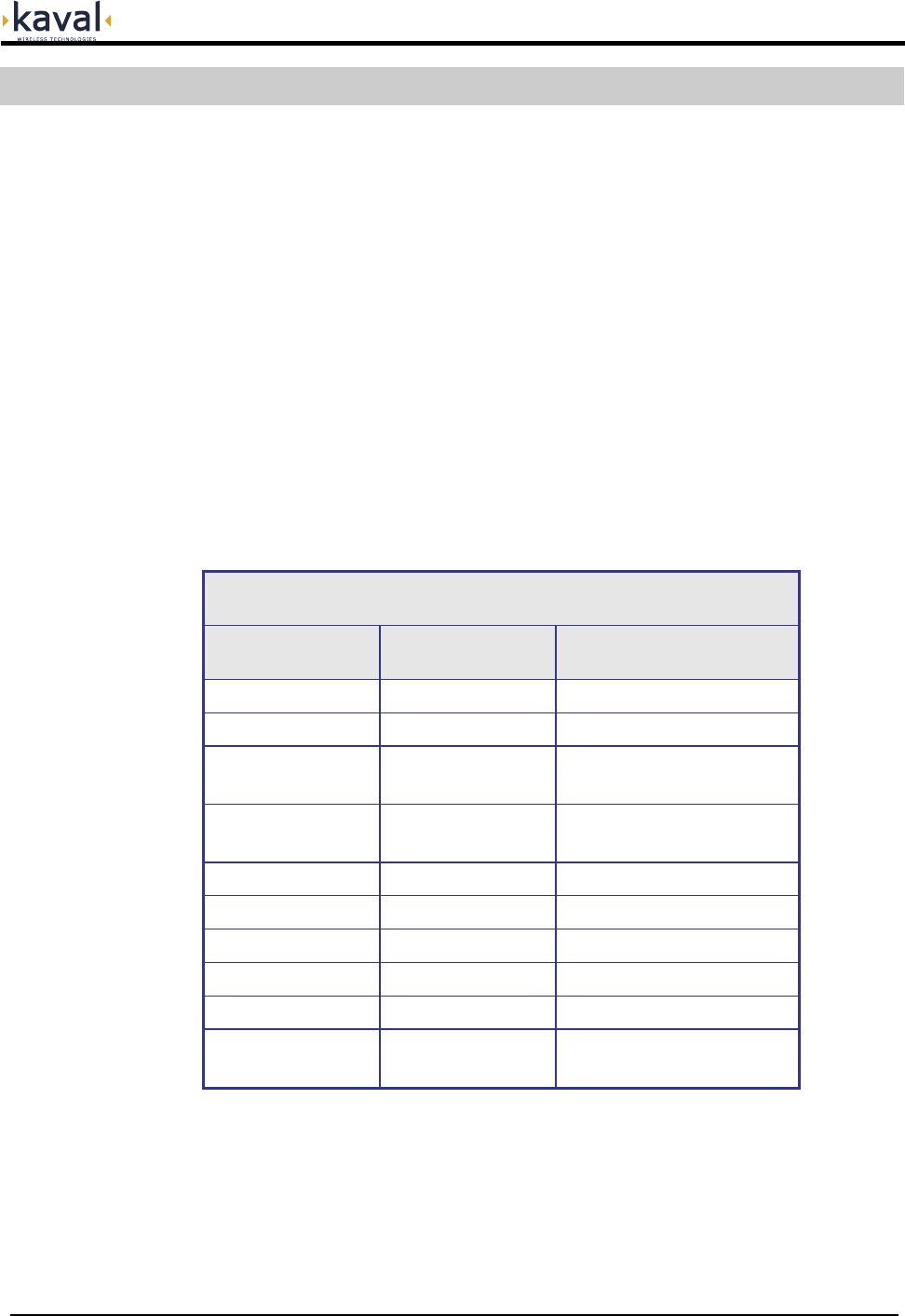
LNKA MODULE FAMILY
MODEL TYPE FREQUENCY
LNKA100-A Broadband Amplifier 136-155 MHz
LNKA100-B Broadband Amplifier 150-174 MHz
LNKA400-A Broadband Amplifier 403-430 MHz
Future Release
LNKA400-B Broadband Amplifier 450-512 MHz
Future Release
LNKA800-A Broadband Amplifier 806-824 MHz
LNKA800-B Broadband Amplifier 851-869 MHz
LNKA800-C Broadband Amplifier 824-849 MHz
LNKA800-D Broadband Amplifier 869-894 MHz
LNKA800-E Broadband Amplifier 896-901 MHz
LNKA800-F Broadband Amplifier
928-940 MHz Capable
929-930 / 935-940 FCC Approved
1. LNKA MODULES
Overview
Models
LinkNet™ LNKA RF MODULES z USER MANUAL DCM000000054
Printed: 03.12.15,10:19
Revision Date:12/15/03 5
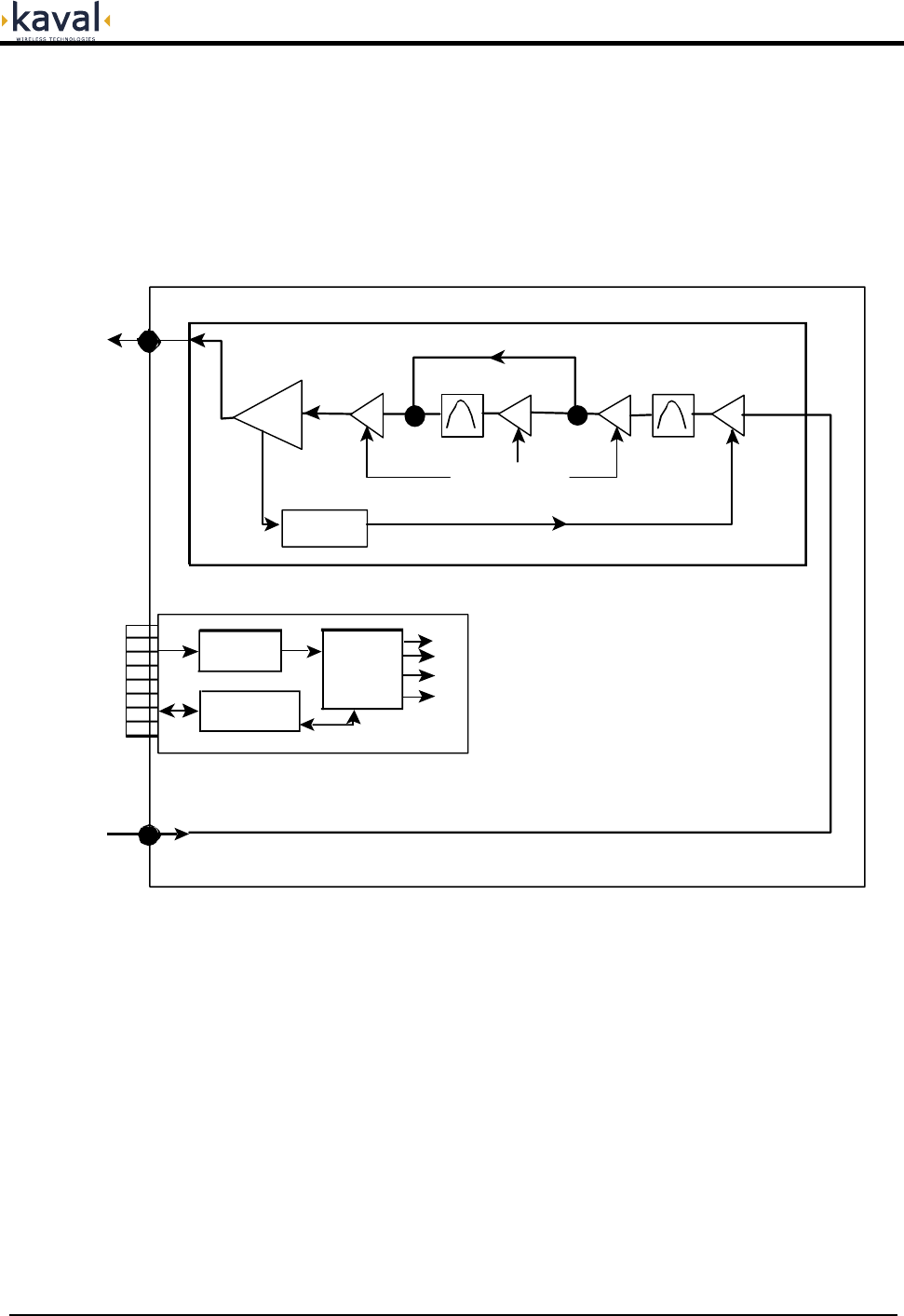
LNKA RF Module
Block diagram
Amplifier Board
UMC Controller Board without TCXO
RF Input
RF Output
Micro-
Controller
with lines to
all Boards
SMA RF
Connector
SMA RF
Connector
Power &
Control to
Backplane
AGC Gain Control Loop
Communication
Interfaces
Gain
Control
Filter
Linear Power Amplifier
Power
Circuits
Filter
Digital Gain Control

LinkNet™ LNKA RF MODULES z USER MANUAL DCM000000054
Printed: 03.12.15,10:19
Revision Date:12/15/03 6
Frequency Bands See Model Chart
Modulation & Channel Spacing Broadband Amplifiers
RF Output Power Capability 1dB Compression Point = +37 dBm Typical
IP3 Intermodulation = +47 dBm Typical
AGC Control Adjustment Range +15 to +30 dBm or Disabled
AGC Attack Time (10%-90%)
AGC Decay Time (90%-10%)
0.5 - 5 mS Typical
50 - 200 mS Typical
RF Gain Adjustment Range +34 to +84 dB
in 1 dB Steps
Gain Variation over Passband 2 dB Maximum
Max RF Input +3 dBm with Min Gain & Max RF Out
Noise Figure <8 dB, 5 dB Typical
Maximum RF Input
Output Level from De-rating Chart minus the Gain.
As an example, for 1 FM Carrier (+37 dBm) at
minimum Gain (+34 dB)
the Maximum RF Input is +3 dBm.
Transmit Duty Cycle Continuous
Transmit Spurious -13 dBm max
Receive Conducted Spurious -57 dBm Max
Group Delay < 200 nS
(< 100 nS Variation across Passband)
Input Return Loss >14 dB
RF Connectors SMA (50) Connectors
Module Power Supply Requirements 40 Watts Maximum
Connections
Edge Connector & 2 SMA RF Connectors, DB-15
Connector on back of Card-Cage provides per-
Module Fault Relay, Interconnect to other
Modules, & RS-232 Connection
Front Panel Indicators Operating, Stand by, Fault, Program Mode
Configuration Options
RF Modules may be configured either via the
optional Controller Module, or via a PC and an
RS-232 Connection via the Card-Cage.
Operating Temperature Range -10 to +50oC; consult Manual DCM000000008 for
cooling requirements
Operating Humidity Range 10 to 90% RH, Non-Condensing
Size & Weight 9.11” High, 2.00” Wide, 14.00” Deep,
10 lbs, 4.5 kg Max
FCC Identifiers
FCC: H6M-LNKA100 VHF (pending)
H6M-LNKA400 UHF (pending)
H6M-LNKA800 800-900MHz
Industry Canada Certifications
IC: 1541A-LNKA100 VHF (pending)
1541A-LNKA400 UHF (pending)
1541311246A 800-900MHz
Also consult the main LinkNet™ Manual DCM000000008.
Module Specifications
LinkNet™ LNKA RF MODULES z USER MANUAL DCM000000054
Printed: 03.12.15,10:19
Revision Date:12/15/03 7
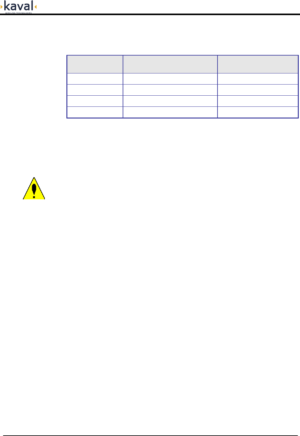
Software Set-up
LNKA modules are shipped with the following factory set options:
OPTION RANGE OF VALUES DEFAULT VALUE
Frequency See Model Chart Order Specific
Gain +34 to +84 dB +34 dB
AGC +15 to +30 dBm or Disabled +30 dBm
Module Enabled On / Off On
Default values may be changed when an order is placed. Check your order
confirmation (shipped with modules) for customized values.
In line with the versatility of the LinkNetTM Platform, it is possible to re-configure the
LNKA module in the field. For further information on the modification software and
the PC adapter, contact KAVAL WIRELESS TECHNOLOGIES by E-mail:
info@kaval.com
Configuration
In line with the versatility of the LinkNetTM Platform, it is possible to re-configure the
LNKA module in the field, either with a Personal Computer (PC) or via the optional
Control Module. To use a PC it is necessary to have a Kaval CAB000000057
Control Cable to connect between the appropriate Module's DB15 connector on the
back of the Card-Cage and the standard DB9 RS232 Connector on the PC. On the
PC a terminal emulation program such as HyperTerminal is used to communicate
to the LinkNet Module. The settings are 9600 baud, 8 bits, no parity, and 1 stop bit.
Commands are one or two words followed by pressing Return. Commands may be
given in upper or lower-case. Available commands are...
ACCESS USER: Required as a simple password to gain access to customer
settable parameters and diagnostics; This will time-out after 10
minutes, and may have to be re-typed.
HELP or ?: Displays a list of Available Commands.
LIST: Displays Current Settings and Status Faults, Etc.
VER: Display the current Version of Software.
ENABLE 1 or 0: Enables or Disables the Module.
GAIN ###: Displays or Sets the Module Gain (in tenths of a dB).
AGCTHRESH ###: Displays or Sets the AGC Level (in tenths of a dBm).
AGCEN 1 or 0: Enables or Disables AGC.
Please consult Kaval Wireless Technologies for further support.
Operation

LinkNet™ LNKA RF MODULES z USER MANUAL DCM000000054
Printed: 03.12.15,10:19
Revision Date:12/15/03 8
De-Rating Chart
To maintain the FCC Spurious Emissions limit of -13 dBm maximum, for multiple
carriers it is necessary to de-rate their power level. For FM carriers, they need to be
de-rated as shown...
Number of Carriers Power per Carrier
1 +37 dBm
2 +26 dBm
3 +24 dBm
4 +22 dBm
5 +20 dBm
6 +19 dBm
7 +18 dBm
8 +17 dBm
9 +16 dBm
10 +15 dBm
15 +13 dBm
20 +11 dBm
25 +10 dBm
30 +9 dBm
For complex CDMA, TDMA, GSM, etc. carriers, typically de-rate by a further 3 to 5
dB. Consult Kaval for more information.
LinkNet™ LNKA RF MODULES z USER MANUAL DCM000000054
Printed: 03.12.15,10:19
Revision Date:12/15/03 9
Power On Self Test (POST)
Each Module automatically performs a self-diagnostics when inserted into the
system Card-cage. These tests determine that the unit is a) correctly installed in the
Card-cage and b) not damaged in transit.
• All six of the LED’s on the front panel will flash 3 times
• If the LED’s do NOT flash three times, then remove the module, check the power
source, and re-insert the module, (See Installation Instructions).
• If the card is “OK” the LED’s will continue normally. (See Normal Operation)
• If there is a fault, then the Red Fault LED will remain on. If this occurs, contact
your KAVAL WIRELESS TECHNOLOGIES Service Representative, (See
Warranty / RMA Procedures).
The Power On Self Test is Not an RF test, it only verifies that there is power to
the unit and that the logical circuitry is functioning.
Fault Indications
Each Module continuously performs internal diagnostics. If a problem is detected it
will activate its Red Fault LED and Fault Relay. Faults detected include...
• Over Temperature
• Misc. Internal Faults
Detailed Faults are detected by the optional Gateway Module. Details may also be
determined via the Module's Control Port Connector and an RS232 connected
Terminal Emulator using the LIST command.
LinkNet™ LNKA RF MODULES z USER MANUAL DCM000000054
Printed: 03.12.15,10:19
Revision Date:12/15/03 10
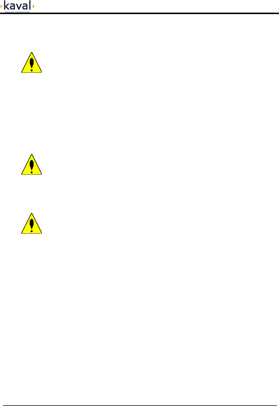
Normal Operation
The LNKA Module has six LED’s on the faceplate:
1. OPERATING - Operating normally.
2. STANDBY – Under the control of the Gateway Module.
3. TRANSMIT – No function on these Modules.
4. RECEIVE – No function on these Modules.
5. PROGRAM – This LED will be constant Amber when the unit is being re-
programmed by the Controller Module. This will signify that the unit is
powered on but unavailable for use.
6. FAULT – Red LED, If the internal diagnostics for the module detect a
problem, then this LED will remain on
LinkNet™ LNKA RF MODULES z USER MANUAL DCM000000054
Printed: 03.12.15,10:19
Revision Date:12/15/03 11
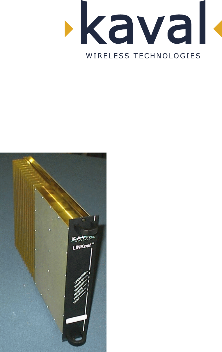
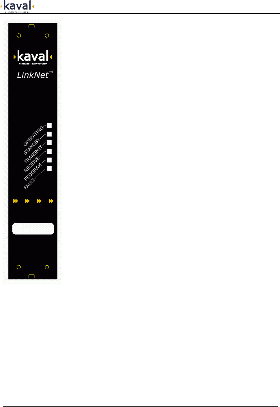
LINKNET LNKA AMPLIFIER MODULE

LinkNet™ LNKA RF MODULES z USER MANUAL DCM000000054
Printed: 03.12.15,10:19
Revision Date:12/15/03 12
• All Antenna Installation to be performed by Qualified Technical Personnel only.
• Antenna Installation Instructions and locations below are for the purpose of
satisfying FCC RF Exposure Compliance requirements.
• Note that if multiple LinkNet™ Modules are used, the Instructions below
apply to the composite power output of all Modules when transmitting
simultaneously.
• The Roof Top Antenna or Antennae for linking to the Donor Site(s) is/are
directional (high gain) Antennae, fixed-mounted physically on the side or top of a
building, or on a tower. The Antenna Gain must be no more than 20 dBi. If
multiple LinkNet™ Modules are used with output combiners into any one
Antenna, and/or multiple Antennae are used on one Roof Top, then the
sum of composite powers into all Roof Top Antennae must not exceed 20
Watts maximum. Please consult Kaval Wireless for assistance as required. The
Roof Top Antennae location should be such that only Qualified Technical
Personnel can access it, and that under normal operating conditions no other
person can touch the Antenna, or approach within 10 meters of the Antenna.
• For the Cellular Uplink Band (824-849 MHz) the Roof Top Antenna or
Antennae for linking to the Donor Site(s) has the added restriction that the
Effective Radiated Power (ERP) must not exceed 7 Watts (+38 dBm). Thus, if
the AGC is set (as per the Carrier De-Rating Chart) to +28dBm as an example,
the maximum allowed Antenna Gain must be no more than 10 dBi.
• The In-Building Antenna connection is via a coaxial cable distribution system
with Signal Taps at various points connected to the fixed-mounted Indoor
Antennae. This is shown in the figure in the Introduction. The Indoor Antennae
are simple 1/4 Wavelength (0 dB Gain) types. They are used with KAVAL
WIRELESS TECHNOLOGIES 12, 16, or 20 dB Cable Taps. As such the
maximum EIRP will be at the first Tapped Antenna, which will be 12 dB below
the maximum signal level of the LinkNet™ (+40 dBm); +28 dBm, or 0.63 Watts
EIRP. If multiple LinkNet™ Modules are used with output combiners, then
the composite power output of all Modules transmitting simultaneously
must meet this maximum EIRP requirement. Please consult Kaval Wireless
for assistance as required. These Antennae are to be installed such that no
person can touch the Antenna, or approach within 0.2 Meters.
Antenna Installation

LinkNet™ LNKA RF MODULES z USER MANUAL DCM000000054
Printed: 03.12.15,10:19
Revision Date:12/15/03 13
ANTENNA INSTALLATION
WARNING
ALL ANTENNA INSTALLATION IS TO BE PERFORMED BY QUALIFIED
TECHNICAL PERSONNEL ONLY.
ANTENNA INSTALLATION INSTRUCTIONS AND LOCATIONS ARE FOR THE
PURPOSE OF SATISFYING FCC RF EXPOSURE COMPLIANCE
REQUIREMENTS, AND ARE NOT OPTIONAL.
ALL ROOF TOP ANTENNA INSTALLATION MUST BE SUCH THAT NO PERSON
CAN TOUCH THE ANTENNA, OR APPROACH CLOSER THAN 10 METERS.
ALL IN-BUILDING ANTENNAE INSTALLATIONS MUST BE SUCH THAT NO
PERSON CAN TOUCH THE ANTENNAE, OR APPROACH CLOSER THAN 0.2
METERS.
• This equipment has been tested and found to comply with the limits for a Class
A digital device, pursuant to Part 15 of the FCC Rules. These limits are
designed to provided reasonable protection against harmful interference when
the equipment is operated in a commercial environment. This equipment
generates, uses, and can radiate radio frequency energy and, if not installed and
used in accordance with the instruction manual, may cause harmful interference
to radio communications. Operation of this equipment in a residential area is
likely to cause harmful interference in which case the user will be required to
correct the interference at his own expense.
WARNING
CHANGES OR MODIFICATIONS NOT EXPRESSLY APPROVED BY KAVAL
COULD VOID THE USER’S AUTHORITY TO OPERATE THE EQUIPMENT.
FCC Information to
Users