Powerwave Technologies LNKA100 LINKNET RF BROADBAND AMPLIFIER MODULE User Manual LinkNet VHF Broad V1 1003
Powerwave Technologies Inc. LINKNET RF BROADBAND AMPLIFIER MODULE LinkNet VHF Broad V1 1003
Contents
- 1. USERS MANUAL
- 2. BROCHURE
BROCHURE

Kaval’s advanced LinkNet VHF Service Module is a digitally controlled Class-A amplifier designed to operate within
the LinkNet Convergence Platform to extend coverage of the vhf (136-174 MHz) spectrum range.
Software configured, this broadband amplifier’s main function is to receive, amplify and transmit its designated
frequency range and to ensure that clean, clear signals arrive at their intended destination.
Because of LinkNet’s modular design, additional service modules can be added to keep pace with technological
advancements or changes in user demand, making LinkNet the most flexible, scalable, and cost-effective solution
on the market today.
Servicing VHF. Broadband Version.
Features & Benefits
Installation & Service Features All LinkNet Service Modules are
‘plug-and-play/unplug-and-remove’ to minimize installation
down time and eliminate the need for extensive service
equipment on site.
Hot Swappable Features LinkNet Service Modules can be added
or replaced within the LinkNet Convergence Platform without
powering down the system. This provides quick and easy
maintenance with no disruption to service.
Diagnostic Features Each LinkNet Service Module automatically
performs a self-diagnostic check when inserted into the chassis.
As well, all major fault conditions are constantly monitored,
including:
Primary power failure
Thermal management
Over-current/under-current
TM Trademark of Kaval Wireless Technologies.
SM Service Mark of Kaval Wireless Technologies.
1.888.86.kaval www.kaval.com Wireless inside. Made possible.
SM
LinkNetTM Service Module
LNKA100
ab
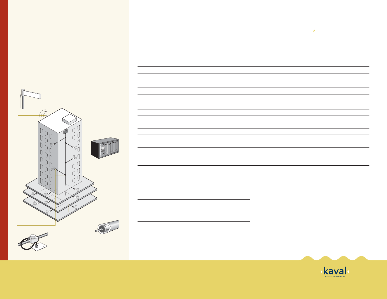
LinkNet™ Convergence Platform
Donor Antenna
Tap-In™ and Ceiling Antenna
Coaxial Cable
Product Deployment
Signals are received via an off air donor antenna located on
the exterior of the building, from a nearby macro cell site.*
The LinkNet Convergence platform converges and amplifies
signals which are then distributed to each floor via coaxial
cable. Kaval’s patented Tap-In signal taps and a series of
ceiling mounted antennas provide balanced coverage
throughout the building.
* Signals may be taken directly from base
station via fiber or T1connection if so desired.
Specifications
Module Specifications
Frequency Range LNKA100-A 136-155 MHz, LNKA100-B 150-174 MHz
Modulation and Bandwidth Broadband Amplifier
RF Gain Adjustment Range +34 dB to +84 dB, in 1 dB increments
AGC Control Adjustment Range +15 dBm to +30 dBm
3rd Order Intercept Point IP3
+47 dBm Typical
Noise Figure
<
8 dB, 5dB Typical
Transmit Duty Cycle Continuous
Transmit Spurious -13 dBm Maximum
Receive Conducted Spurious -57 dBm Maximum
Power Module Supply Requirements 40 Watts Maximum
Group Delay
<
5 µs
RF Connectors SMA (50 Ω) Connectors on back of Chassis
Connections DB-15 Connector on back of Chassis provides Per-Module Fault Relay,
Interconnect to other Modules, and RS-232 connection.
Front Panel Indicators Operating, Stand By, Fault, Program Mode, Receive, Transmit
Configuration Options Modules may be configured via optional Gateway Module, or via PC and a RS-232 Connection
V1-10/03
1.888.86.kaval www.kaval.com Wireless inside. Made possible.
SM
Mechanical Characteristics
Dimensions (W x H x D) 2" x 9.11" x 14"
Weight 10 lbs. approx.
Operating Temperature Range* -100C to +500C
Operating Humidity Range 10 to 90% RH, Non-Condensing
* Consult Kaval for installation specific forced-air cooling requirements.
Specifications are subject to change without notice.
LinkNetTM Service Module
LNKA100