Powerwave Technologies LNKFIB-R LNKFIB-R User Manual users manual
Powerwave Technologies Inc. LNKFIB-R users manual
users manual
SatelLink
SatelLinkSatelLink
SatelLink RF
RF RF
RF -
--
- FIBER
FIBER FIBER
FIBER
Interface Modules
Interface ModulesInterface Modules
Interface Modules
User Manual
User ManualUser Manual
User Manual
Installation, Operation
Installation, OperationInstallation, Operation
Installation, Operation
And Maintenance
And MaintenanceAnd Maintenance
And Maintenance
KAVAL WIRELESS TECHNOLOGIES
60 Gough Road
Markham, Ontario, L3R 8X7
Telephone: (888) 86-KAVAL
Web: www.kaval.com
E-mail: info@kaval.com
Document #DCM000000052, Rev.1
May 11, 2001

SatelLink
! USER MANUAL
DCM000000052
Printed: 2001-05-11 14:10:44
Revision Date: 5/11/01: ii
P
PP
P
P
PP
PR
RR
R
R
RR
RO
OO
O
O
OO
OP
PP
P
P
PP
PR
RR
R
R
RR
RI
II
I
I
II
IE
EE
E
E
EE
ET
TT
T
T
TT
TA
AA
A
A
AA
AR
RR
R
R
RR
RY
YY
Y
Y
YY
Y
S
SS
S
S
SS
ST
TT
T
T
TT
TA
AA
A
A
AA
AT
TT
T
T
TT
TE
EE
E
E
EE
EM
MM
M
M
MM
ME
EE
E
E
EE
EN
NN
N
N
NN
NT
TT
T
T
TT
T
© 2000 KAVAL WIRELESS TECHNOLOGIES All rights reserved.
No part of this publication, or any software included with it may be reproduced, stored in a retrieval system,
or transmitted in any form or by any means, including photocopying, electronic, mechanical, recording or
otherwise, without the prior written permission of the copyright holder.
This document contains proprietary information of KAVAL WIRELESS TECHNOLOGIES The contents are
confidential and any disclosure to persons other than the officers, employees, agents or subcontractors of
the owner or licensee of this document, without the prior written consent of KAVAL WIRELESS
TECHNOLOGIES, is strictly prohibited.
KAVAL WIRELESS TECHNOLOGIES provides this document as is, without any warranty of any kind either
expressed or implied including, but not limited to, the implied warranties of merchantability and fitness of a
particular purpose. KAVAL WIRELESS TECHNOLOGIES may make changes or improvements in the
equipment, software, or specifications described in this document at any time and without notice. These
changes will be incorporated in new releases of this document.
This document may contain technical inaccuracies or typographical errors. KAVAL WIRELESS
TECHNOLOGIES waives responsibility for any labour, materials, or costs incurred by any person or party as
a result of using this document. KAVAL WIRELESS TECHNOLOGIES, and any of its affiliates shall not be
liable for any damages (including, but not limited to, consequential, indirect or incidental, special damages or
loss of profits or date) even if they were foreseeable and KAVAL WIRELESS TECHNOLOGIES has been
informed of their potential occurrence, arising out of or in connection with this document or its use.
T
TT
T
T
TT
TR
RR
R
R
RR
RA
AA
A
A
AA
AD
DD
D
D
DD
DE
EE
E
E
EE
E
M
MM
M
M
MM
MA
AA
A
A
AA
AR
RR
R
R
RR
RK
KK
K
K
KK
K
N
NN
N
N
NN
NO
OO
O
O
OO
OT
TT
T
T
TT
TI
II
I
I
II
IC
CC
C
C
CC
CE
EE
E
E
EE
E
This manual makes reference to trademarks that are the property of other companies. References are used
only to refer to the products or services of the trademark owners.
SatelLink is a trademark of KAVAL WIRELESS TECHNOLOGIES

SatelLink
! USER MANUAL
DCM000000052
Printed: 2001-05-11 14:10:44
Revision Date: 5/11/01: iii
TABLE OF
TABLE OF TABLE OF
TABLE OF
CONTENTS
CONTENTSCONTENTS
CONTENTS
1.
SATELLINK MODULES ...........................4
O
VERVIEW
.............................................................. 4
Theory Of Operation ......................................... 4
M
ODELS
................................................................. 4
B
LOCK
D
IAGRAMS
................................................... 5
SatelLink Head-End Module............................. 5
SatelLink Remote Module................................ 6
C
ONNECTIONS
........................................................ 7
SatelLink Head-End Module............................. 7
SatelLink Remote Module................................ 8
SatelLink Head-End to Remote Interconnects10
M
ODULE
S
PECIFICATIONS
.....................................11
R
EMOTE
M
ODULE
P
ER
-C
ARRIER
D
E
-R
ATING
.........12
O
PERATION
..........................................................13
Normal Operation............................................13
Configuration...................................................13
L
ASER
S
AFETY
.....................................................14
A
NTENNA
I
NSTALLATION
........................................15
SatelLink
! USER MANUAL
Printed: 01.05.11,14:10
Revision Date:5/11/01 4
Theory Of Operation
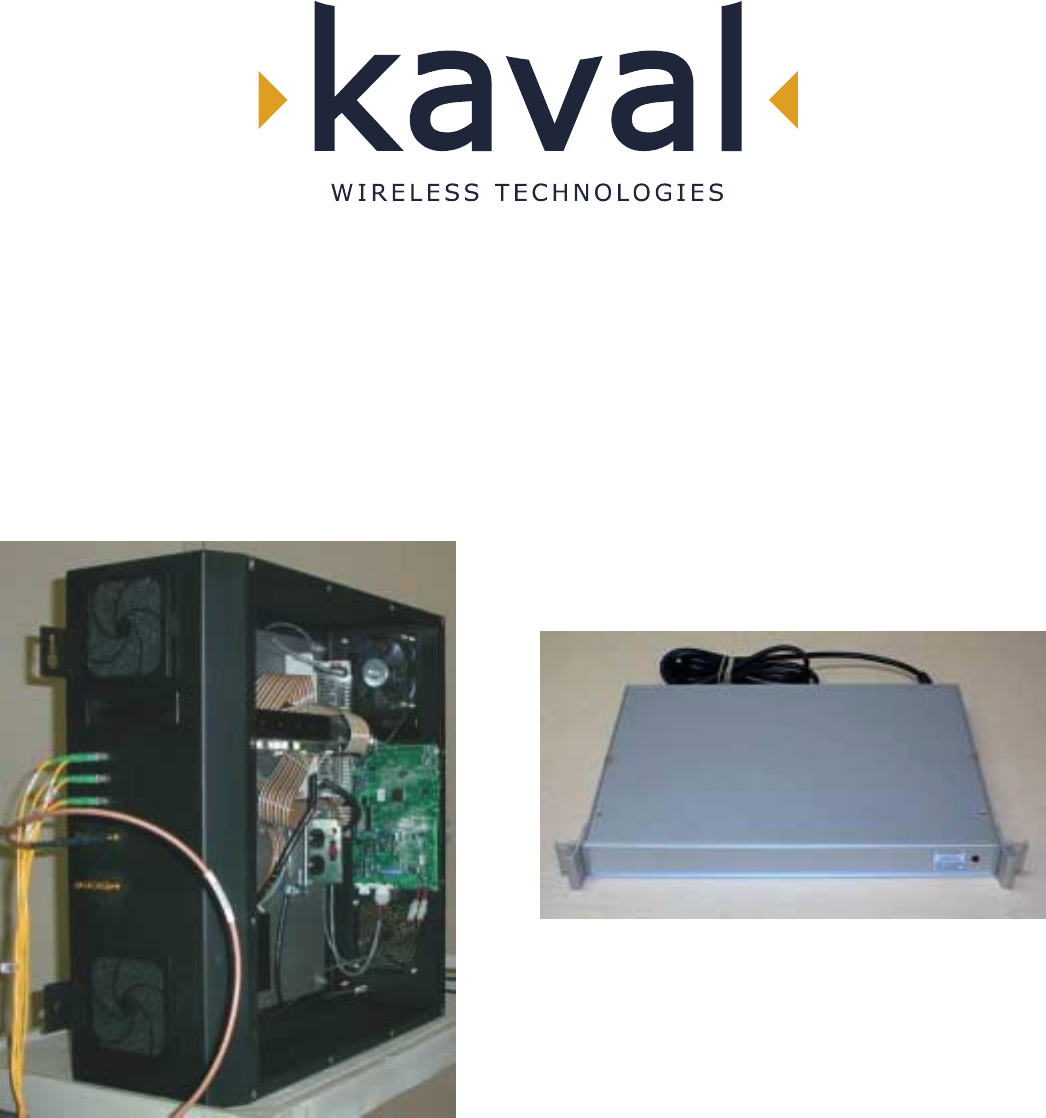
The SatelLink RF to Fiber Modules provide a multi-band, multi-service link from a
main distribution center to multiple local antennae. RF Signals are distributed in runs
of three pairs of
Single-Mode Fiber-Optic Distribution Lines, organized as...
Fiber Pair #1: 1.9 GHz PCS Services
Fiber Pair #2: 800 MHz Cellular Services
Fiber Pair #3: 800 MHz iDEN & Paging Services
There are two models....
SatelLink
MODEL DESCRIPTION
LNKFIB-H01
This is a 1U high, 19" Rack-Mount Module providing low signal
level interfacing between Head-End RF Modules and Single-Mode
Fiber-Optic Distribution Lines. One is used for each of the three
Fiber Pair Groups, and can service up to four Remote Modules.
LNKFIB-R01 This is a Wall-Mounted Remote Module that connects to the Single-
Mode Fiber-Optic Distribution Lines and provides eight local
Distribution Antennae for Signal Extension.
NOTE:
With these Modules, there is always a grouping of three (3) of LNKFIB-H01's to
every four (4) LNKFIB-R01's.
1. SATELLINK MODULES
Overview
Models
SatelLink
! USER MANUAL
Printed: 01.05.11,14:10
Revision Date:5/11/01 5
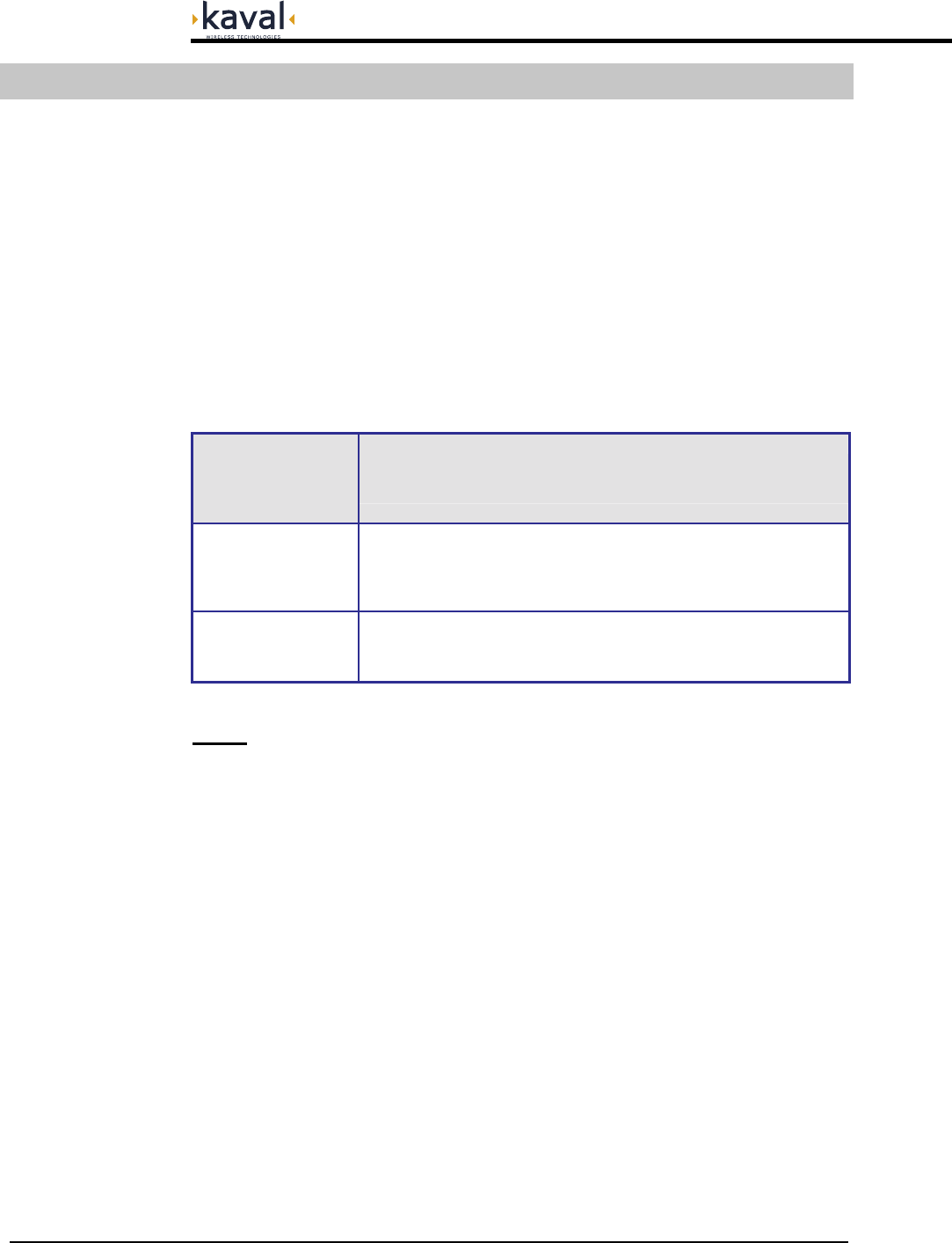
SatelLink Head-End Module
Block Diagrams
SM F.O. In
SM F.O. Out
(PIN Diodes)
(Lasers)
Power Supply
Moni tor s
FO Laser and PIN Diode
120 / 240 VAC
120/240 VAC Fault Relay
PreAmp
Laser Diode
PreAmps
RF Out #1
RF Out #2
RF Out #3
RF Out #4
RF Input
SatelLink
! USER MANUAL
Printed: 01.05.11,14:10
Revision Date:5/11/01 6
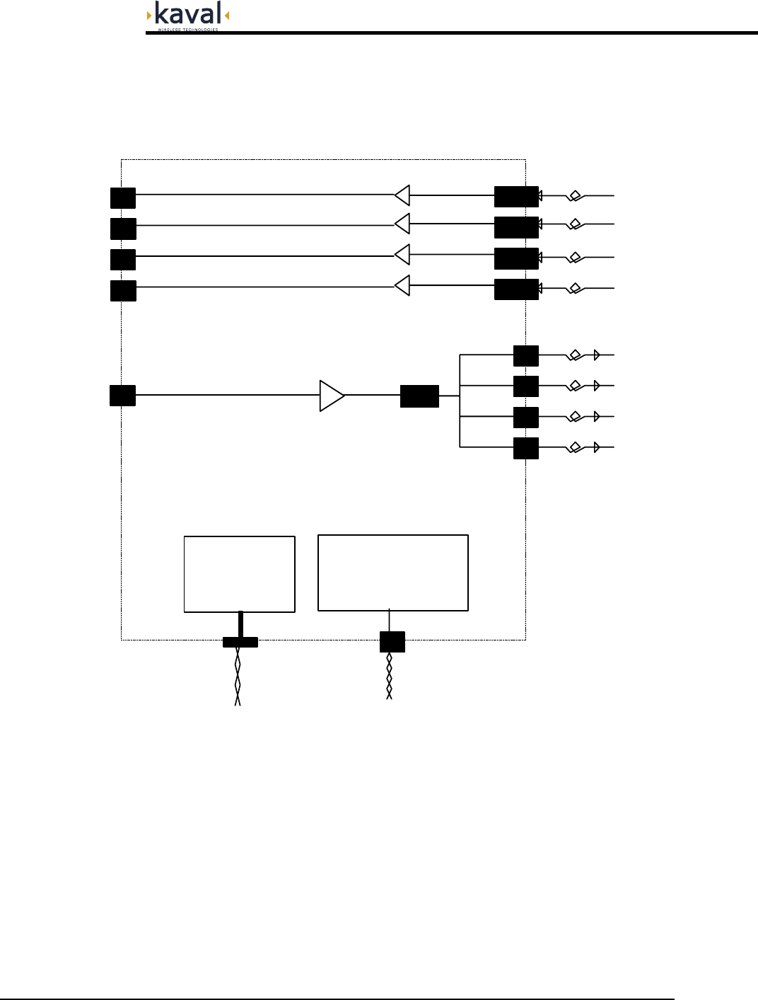
SatelLink Remote Module
SM F.O. In
SM F.O. Out
(PIN Diodes)
(Lasers)
Four
Antenna
Ports
1.9GHz PCS
Cellular
Power Supply
Moni to r s
& Power Amp
Loose
Couplers
RF Monitor
2 RF Ports to
Ports
FO Current
120 / 240 VAC
Micro-Controller
Circuitry
120/240 VAC
CAN Interface RS232 Interface
To Head-End To PC
Green Power On LED
Red Fault LED
Fault Relay
24 VDC Battery
PreAmps
IDEN & Paging
PreAmps
1.9G Hz PCS
Cellular
IDEN & Paging
869-894 MHz
1.9 GHz
851-866 MHz
1.8 GHz
824-849 MHz
806-821 MHz
Notch 851+ MHz
Notch 894- MHz
928-941 MHz
899-902 MHz
Antennae on
Alternate Floor
1.9G Hz PA
800-900MHz PA
SatelLink
! USER MANUAL
Printed: 01.05.11,14:10
Revision Date:5/11/01 7
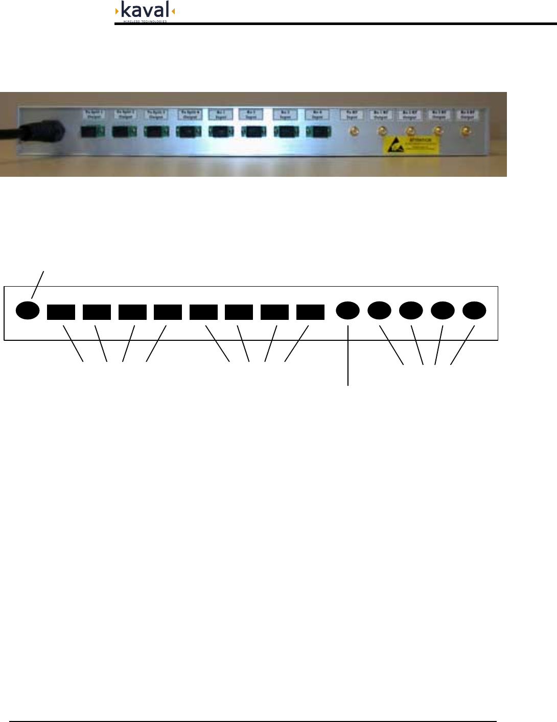
SatelLink Head-End Module
The Head-End has one Downlink RF Input providing the signal for four Downlink
Optical Outputs, thus each Head-End Module services one and only one of the three
Fiber-Pairs (PCS, Cellular, or iDEN/Trunking).
Connections
Head-End Connections
SC/APC SingleMode Fiber-Optic & SMA RF Connectors
AC Power Cord
Downlink Optical Outputs
TX1 TX2 TX3 TX4 RX1 RX2 RX3 RX4
Uplink Optical Inputs
TX In RX1 RX2 RX3 RX4
Downlink RF Input
Uplink RF Outputs
SatelLink
! USER MANUAL
Printed: 01.05.11,14:10
Revision Date:5/11/01 8
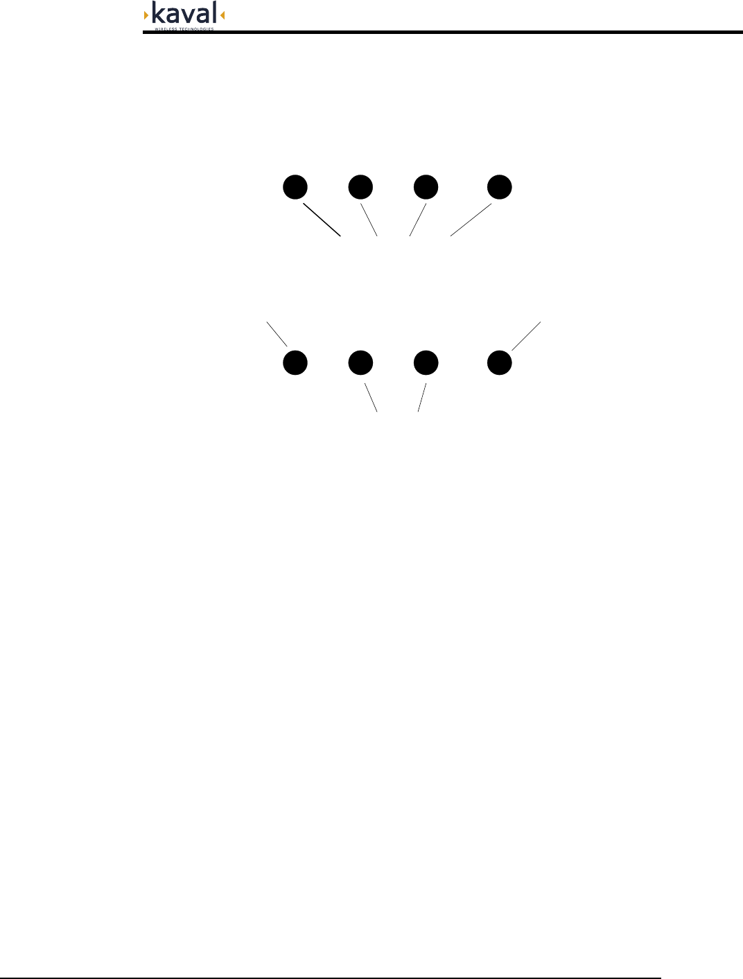
SatelLink Remote Module
Antenna Port Connections
Four Direct Antenna Connections
Two Expansion Antenna Connections
Uplink Sampler Port Downlink Sampler Port
SMA Connections
The Remote Module has 8 SMA RF Connections..
Main Antenna Ports (4): Used to connect to four identical distributed indoor
antenna systems.
Expansion Antenna Ports (2): Connected to a secondary location via 2 of two-way
combiners, and in turn provide connections to four
more identical distributed indoor antenna systems.
Sampler Ports (2): Optionally allow an operator to monitor the Uplink
and Downlink RF activity at approx. 30dB below the
actual levels.

SatelLink
! USER MANUAL
Printed: 01.05.11,14:10
Revision Date:5/11/01 9
Fiber Optic Port Connections
PCS Uplink Optical Output PCS Downlink Optical Input
Cellular Uplink Optical Output
iDEN/Paging Uplink Optical Output
Cellular Downlink Optical Input
iDEN/Paging Downlink Optical Input
SC/APC SingleMode Fiber-Optic Connectors
The Remote Module has 6 SC/APC Single-Mode Fiber-Optic Connections for
cabling to the Head-End...
PCS Up & Downlink: Used for the PCS Fiber-Optic Pair connection to the
Head-End.
Cellular Up & Downlink: Used for the Cellular Fiber-Optic Pair connection to
the Head-End.
iDEN/Paging Up & Downlink: Used for the combined iDEN / Paging Fiber-Optic
Pair connection to the Head-End.
SatelLink
! USER MANUAL
Printed: 01.05.11,14:10
Revision Date:5/11/01 10
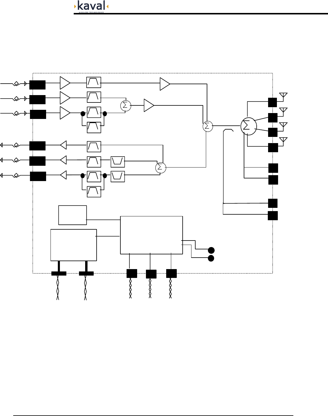
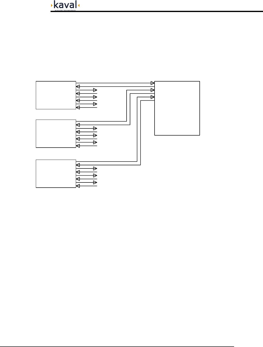
SatelLink Head-End to Remote Interconnects
The Single-Mode Fiber-Optic interconnections between the Head-End and Remote
Modules are based upon the Head-Ends being organized on a "per Fiber-Pair"
system. This fundamentally means that an installation requires three Head-Ends for
every four Remote Modules. It also means that if you have a fully optimized system
with all Head-End ports in use, and you add one more Remote Module, then another
three Head-End Modules are required.
Head-End to Remote Fiber-Optic Connections
Groupings of 3 Head-Ends to every 4 Remotes
PCS Head-End
Cell Head-End
Head-End
iDEN / Paging
Remote Module
Remote Modules
To 3 More
Remote Modules
To 3 More
Remote Modules
To 3 More

SatelLink
! USER MANUAL
DCM000000052
Printed: 01.05.11,14:10
Revision Date:5/11/01 11
Frequency Bands
Downlink: 851-866 MHz iDEN
869-894 MHz Cellular
928-941 MHz Paging
1930-1990 MHz PCS
Uplink: 806-821 MHz iDEN
824-849 MHz Cellular
896-902 MHz Paging
1850-1910 MHz PCS
Maximum Power
from any one of eight
Remote Module Antenna Ports
iDEN/Cell/Paging Combined:
+35 dBm IP3 Typical
PCS Combined:
+33 dBm IP3 Typical
Gains
from any one of eight\
Remote Module Antenna Ports
referenced to Head-End Unit,
assuming 0dB Fiber-Optic Link
Downlink: +28 dB Maximum
(7 dB Gain Reduction
Adjustment Range per Band)
Uplink: -4 to +2 dB
Uplink Noise
at the Head-End Unit from
any one of eight
Remote Module Antenna Ports
assuming 0dB Fiber-Optic Link
< -130 dBm/Hz (Spec. Goal)
Uplink Isolation
from any one of eight
Remote Module Antenna Ports
to the Head-End Unit RF output
assuming 0dB Fiber-Optic Link
Any to Any Band: -60 dB Max, -70dB Typ.
except...
iDEN to Cell: -37 dB Max, -65dB Typ.
Cell to Paging: -45 dB Max, -70dB Typ.
PCS to PCS: -45 dB Max, -65dB Typ.
Downlink Isolation Not Spec., Relies upon Head-End Filtering
Duty Cycle Continuous
Spurious Outputs -13 dBm max per Remote Module Antenna Port
when operated as per De-rating Chart
Optical Power Level
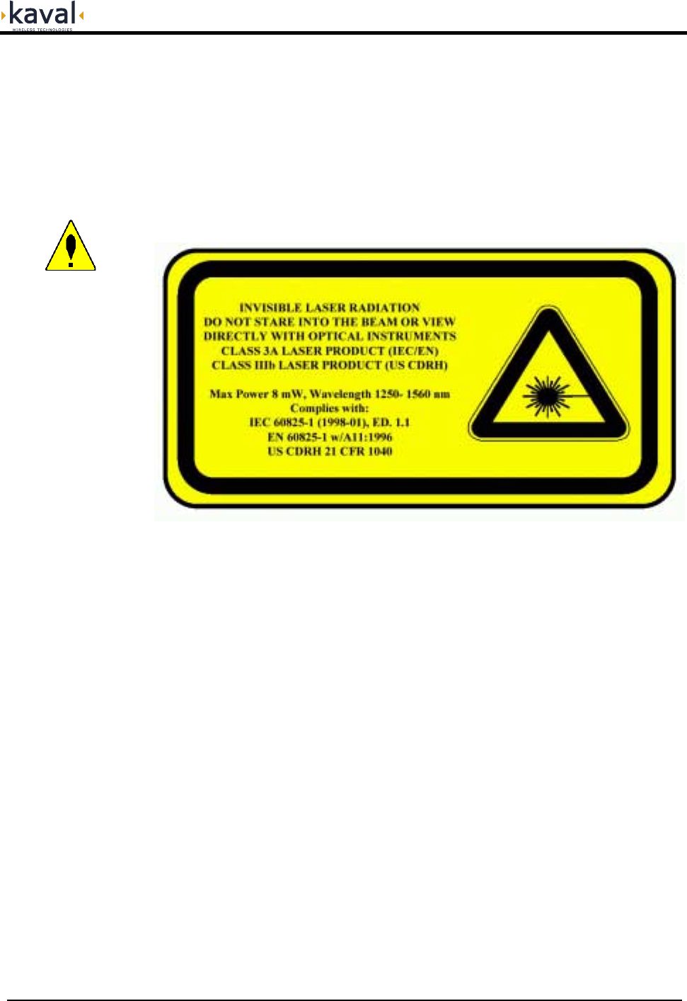
Laser Warning: Invisible Laser Radiation emitting
from optical connector. Avoid direct exposure to
beam. 150 mW max. @1300nm. Class IIIb. Product
complies with 21 CFR 1040.10 and 1040.11.
Optical Path Loss 2 dBO Maximum
Group Delay <8uS (Spec. Goal)
NOT including Fiber-Optic Link
Connectors SC/APC Fiber-Optic, SMA (50Ω) RF
D-Sub Data & Control, 3-Pin AC Power
Head-End Module Power Supply Requirements 120 VAC, 50/60 Hz
120 VA Typical, 200 VA Maximum
Remote Module Power Supply Requirements 120/240 VAC, 50/60 Hz
120 VA Typical, 200 VA Maximum
Configuration Options May be configured either via the SatelLink network
and the Head-End Control Module, or via a PC and
an RS-232 Connection.
Operating Temperature Range -10 to +40
o
C
Operating Humidity Range 5 to 90% RH, Non-Condensing
Head-End Module Size & Weight 1U High 19” Rack Unit, 14" Deep
xx lbs, xx kg Max (TBD)
Remote Module Size & Weight
24” High, 24” Wide, 9” Deep,
NOT incl. mounting tabs
xx lbs, xx kg Max (TBD)
Module Specifications
SatelLink
! USER MANUAL
DCM000000052
Printed: 01.05.11,14:10
Revision Date:5/11/01 12
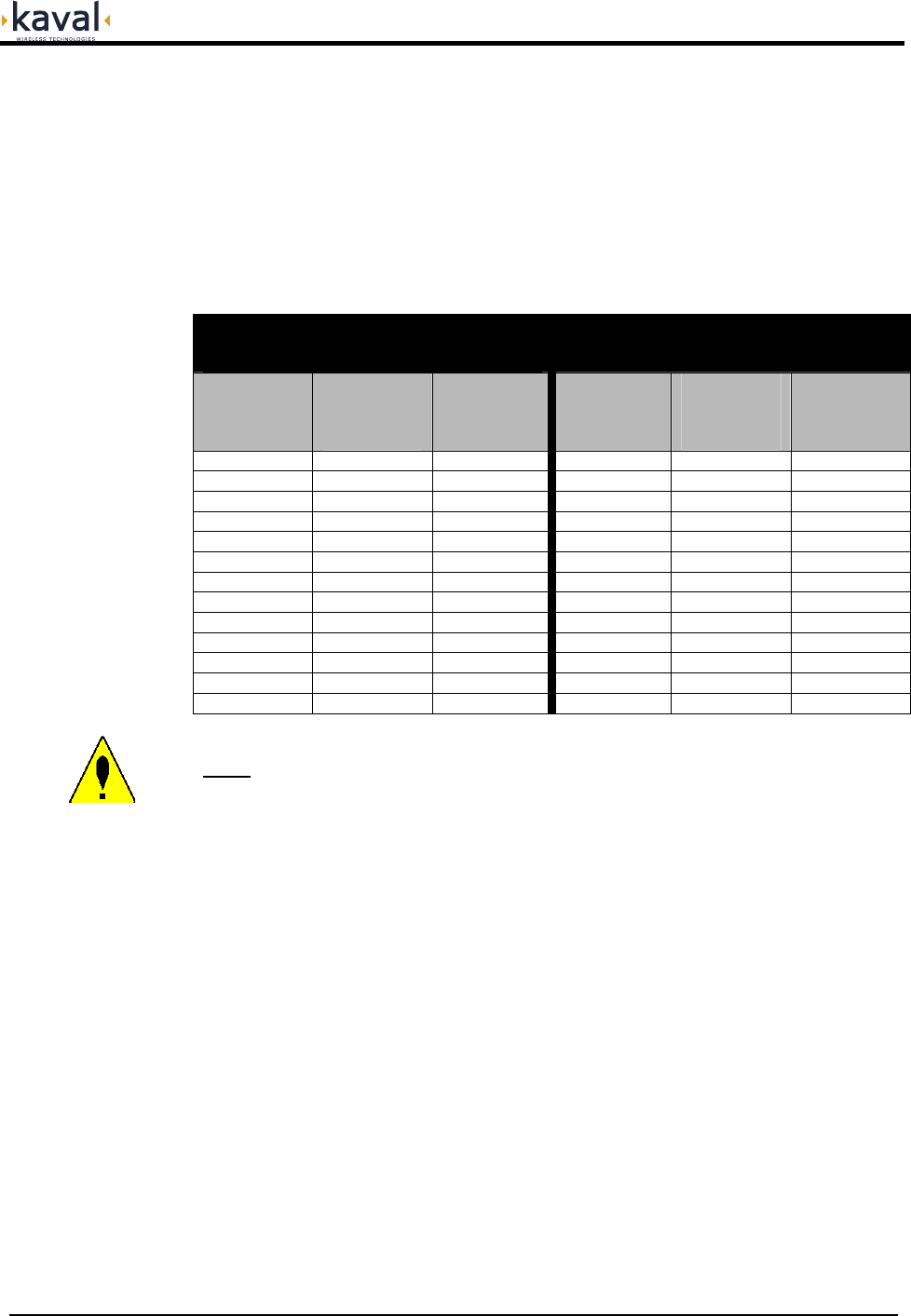
All signals that fall within a given Pass-Band range will “share” power amongst them.
A multiple channel effect is Intermodulation - signals produced from non-linear
effects between the intended channel signals. This intermodulation may cause
interference to receiving equipment. In order to minimize Intermodulation signals,
Power de-rating must be applied. In the USA there are FCC Intermodulation
Specifications published in the EIA Standard PN2009. The Tables below gives the
maximum per channel Output Levels allowed as a function of the number of
channels. Note that depending on the actual input levels, the gain may need to be
reduced to comply with the above regulations.
iDEN / Cellular / Paging
(effective IP3 per Antenna = +35dBm)
(the power is shared in these 3 bands)
1.9 GHz PCS
(effective IP3 per Antenna = +33dBm)
Number of
Carriers Power per
Carrier per
Antenna
Port (dBm)
Total Power
per Antenna
Port (dBm)
Number of
Carriers Power per
Carrier per
Antenna
Port (dBm)
Total Power
per Antenna
Port (dBm)
2 +18.7 +21.7 2 +17.4 +20.4
3 +16.0 +20.7 3 +14.6 +19.4
4 +14.0 +20.0 4 +12.7 +18.7
5 +12.5 +19.5 5 +11.2 +18.2
6 +11.3 +19.1 6 +10.0 +17.8
7 +10.3 +18.8 7 +9.0 +17.5
8 +9.5 +18.5 8 +8.2 +17.2
9 +8.7 +18.3 9 +7.4 +16.9
10 +8.1 +18.1 10 +6.7 +16.7
15 +5.5 +17.3 15 +4.2 +16.0
20 +3.8 +16.8 20 +2.4 +15.4
25 +2.4 +16.4 25 +1.1 +15.1
30 +1.3 +16.1 30 0.0 +14.8
Note: The above levels are for Analog Narrowband FM. For CDMA, TDMA, GSM
Signals the levels must be typically 3 to 5 dB lower than those shown. Consult Kaval
Wireless Technologies for further information.
Remote Module Per-
Carrier De-Rating
SatelLink
! USER MANUAL
DCM000000052
Printed: 01.05.11,14:10
Revision Date:5/11/01 13
Normal Operation
The SatelLink Head-End Module has one LED on the faceplate:
1. OPERATING - Normally this LED will be GREEN.
The SatelLink Remote Module has three LED’s on the faceplate:
1. OPERATING - Normally this LED will be GREEN.
2. FAULT – Red LED, If the internal diagnostics for the module detect a
problem, then this LED will remain on
3. LASERS ON - This LED will be GREEN when any one of the three Lasers
are operating.
Configuration
It is possible to re-configure the LNKFIB-R01 Remote Module in the field, either
with a Personal Computer (PC) or via the optional LinkNet Control Module. To
use a PC it is necessary to connect the DB9 RS-232 connector on the Module to a
standard DB9 RS232 Connector on the PC. On the PC a terminal emulation
program such as HyperTerminal is used to communicate to the LinkNet Module.
The settings are 9600 baud, 8 bits, no parity, and 1 stop bit. Commands are one or
two words followed by pressing Return. Commands may be given in upper or lower-
case. Available commands are...
ACCESS USER: Required as a simple password to gain access to customer
settable parameters and diagnostics; This will time-out after 10
minutes, and may have to be re-typed.
HELP or ?: Displays a list of Available Commands.
LIST: Displays Current Settings and Status Faults, Etc.
VER: Display the current Version of Software.
ENABLE 1 or 0: Enables or Disables the Module.
GAINPCS ###: Displays or Sets the PCS Transmit Gain (in tenths of a dB).
GAINCELL ###: Displays or Sets the Cellular Transmit Gain (in tenths of a dB).
GAINPAGE ###: Displays or Sets the iDEN and Paging Transmit Gain (in tenths of
a dB).
Please consult Kaval Wireless Technologies for further support.
Operation
SatelLink
! USER MANUAL
DCM000000052
Printed: 01.05.11,14:10
Revision Date:5/11/01 14
•
Both the Head-End and Remote Modules have Class IIIb Laser Devices as
Fiber-Optic Transmitters.
•
Under normal installation both Modules are intrinsically-safe (Class I) since the
Fiber-Optic cabling will be installed.
•
Only qualified service personnel should remove / install the Fiber-Optic
cabling!
Laser Safety
SatelLink
! USER MANUAL
DCM000000052
Printed: 01.05.11,14:10
Revision Date:5/11/01 15
•
All Antenna Installation to be performed by Qualified Technical Personnel only.
•
Antenna Installation Instructions and locations below are for the purpose of
satisfying FCC RF Exposure Compliance requirements.
•
The In-Building Antenna connection is via a coaxial cable distribution system
with Signal Taps at various points connected to the fixed-mounted Indoor
Antennae. This is shown in the figure in the Introduction. The Indoor Antennae
are simple 1/4 Wavelength (0 dB Gain) types. They are used with KAVAL
WIRELESS TECHNOLOGIES 12, 16, or 20 dB Cable Taps. As such the
maximum EIRP will be at the first Tapped Antenna, which will be 12 dB below
the maximum signal level of the SatelLink (+40 dBm); +28 dBm, or 0.63 Watts
EIRP. If multiple SatelLink Modules are used with output combiners, then
the composite power output of all Modules transmitting simultaneously
must meet this maximum EIRP requirement. Please consult Kaval Wireless
for assistance as required. These Antennae are to be installed such that no
person can touch the Antenna, or approach within 0.2 Meters.
ANTENNA INSTALLATION
WARNING
ALL ANTENNA INSTALLATION IS TO BE PERFORMED BY QUALIFIED
TECHNICAL PERSONNEL ONLY.
ANTENNA INSTALLATION INSTRUCTIONS AND LOCATIONS ARE FOR THE
PURPOSE OF SATISFYING FCC RF EXPOSURE COMPLIANCE
REQUIREMENTS, AND ARE NOT OPTIONAL.
ALL IN-BUILDING ANTENNAE INSTALLATIONS MUST BE SUCH THAT NO
PERSON CAN TOUCH THE ANTENNAE, OR APPROACH CLOSER THAN 0.2
METERS.
Antenna Installation