Powerwave Technologies MCPA4080 PCS Multicarrier Ultra-Linear Power Amplifier User Manual revised
Powerwave Technologies, Inc. PCS Multicarrier Ultra-Linear Power Amplifier revised
UserManual.wiki
>
Powerwave Technologies
>
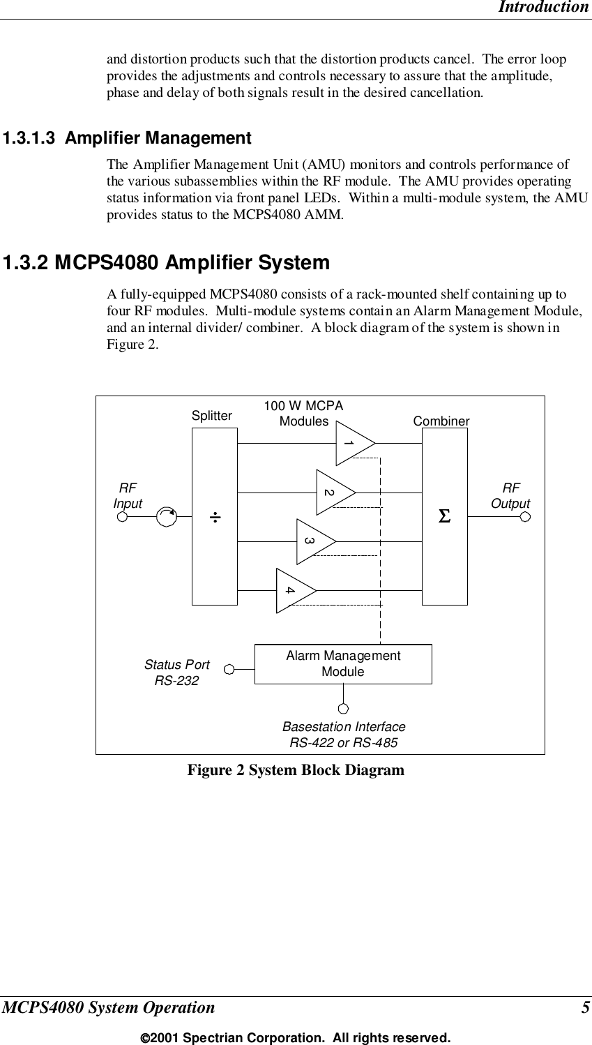
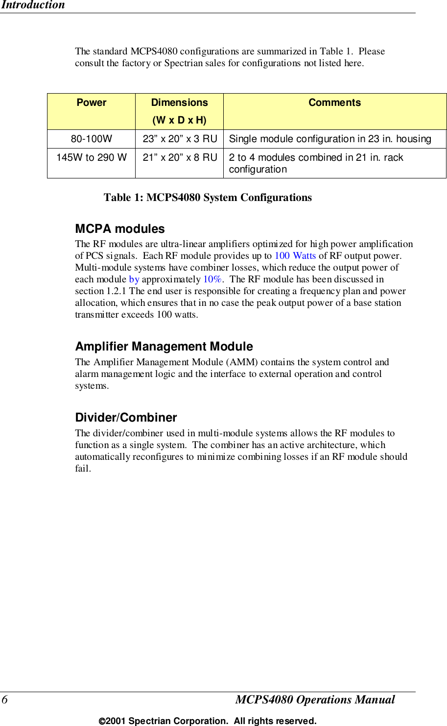
MCPA4080 User Manual
revised user manual
Navigation menu
Upload a User Manual
Namespaces
Wiki Guide
HTML
PDF
Info
Views
User Manual
Discussion / Help
Navigation