Powerwave Technologies MCPS2135 MultiCarrier Amplifier System User Manual 1 1
Powerwave Technologies, Inc. MultiCarrier Amplifier System 1 1
User Manual

SPECTRIAN
MCPS2135 SERIES
MCPA
MultiCarrier Amplifier Systems
INSTALLATION & OPERATION
MANUAL
July 2001

IntroductionPlanning and PreparationIntroduction
ii MCPS2135 Operations Manual
2001 Spectrian Corporation. All rights reserved.
2001 Spectrian Corporation. This document contains
proprietary information of Spectrian Corporation . No part of this
manual may be copied or disclosed without written authorization
of Spectrian Corporation. All rights reserved.

IntroductionPlanning and PreparationIntroduction
MCPS2135 System Operation iii
2001 Spectrian Corporation. All rights reserved.
TABLE OF CONTENTS
1 Introduction .................................................................................................................................................11
1.1 About this Manual...............................................................................................................................11
1.2 Safety Information ..............................................................................................................................22
1.3 Introduction to the MCPS2135 Family ...........................................................................................22
1.3.1 MCPA Module Functional Description .................................................................................44
1.3.2 MCPS2135 Amplifier System .................................................................................................55
2 Planning and Preparation............................................................................................................................77
2.1 Installation Planning ...........................................................................................................................77
2.2 Site Planning Guide ............................................................................................................................77
2.2.1 Site Considerations....................................................................................................................77
2.2.2 Rack Installation Considerations.............................................................................................88
2.2.3 Cable Connections.....................................................................................................................99
2.3 Determine the required RF input power......................................................................................1010
2.3.1 Set RF input drive power for each channel........................................................................1111
2.4 Prepare for Installation...................................................................................................................1212
2.4.1 Inventory Received Equipment ...........................................................................................1212
2.4.2 Unpack Received Equipment...............................................................................................1212
2.4.3 Repackaging for Return Shipment ......................................................................................1413
3 MCPS2135 Installation...........................................................................................................................1514
3.1 Introduction......................................................................................................................................1514
3.2 Task safety equipment, tools and materials ................................................................................1514
3.3 Rack Installation..............................................................................................................................1615
3.3.1 Install Shelf Subassembly .....................................................................................................1615
3.3.2 Install Modules in Shelf........................................................................................................1716
3.4 Cable and Wire Connections.........................................................................................................1716
3.4.1 Connect Chassis Ground Wire .............................................................................................1716
3.4.2 Connect DC Input Power Cables.........................................................................................1716
3.4.3 Connect RF Output and Input Cables.................................................................................1817
3.4.4 Connect Alarm Interface Cables..........................................................................................1918
3.5 Finish Installation............................................................................................................................1918
3.5.1 Set the MCPS2135 unit address..........................................................................................1918
3.5.2 Verify Installation ..................................................................................................................1918
4 System Start-Up .......................................................................................................................................2119
4.1 Introduction......................................................................................................................................2119
4.2 Safety Information and Tools........................................................................................................2119
4.3 Verify system installation ..............................................................................................................2119

IntroductionPlanning and PreparationIntroduction
iv MCPS2135 Operations Manual
2001 Spectrian Corporation. All rights reserved.
4.4 Power Up the MCPS2135..............................................................................................................2220
5 MCPS2135 System Monitoring ............................................................................................................2321
5.1 Introduction......................................................................................................................................2321
5.2 Monitoring the MCPS2135 System Operation ..........................................................................2321
5.3 Alarm Definitions............................................................................................................................2321
5.3.1 Alarm classification ...............................................................................................................2321
5.3.2 Alarm Responses....................................................................................................................2422
5.4 MCPS2135 Alarm Limits and Protection Circuits ....................................................................2523
5.4.1 MCPA Module Analog Protection Circuits.......................................................................2523
5.4.2 MCPA Module Alarms .........................................................................................................2624
5.4.3 MCPA System Alarms ..........................................................................................................2725
6 Troubleshooting and Maintenance........................................................................................................2826
6.1 Introduction......................................................................................................................................2826
6.1.1 Safety Information .................................................................................................................2826
6.2 Troubleshooting...............................................................................................................................2927
6.2.1 Using LED Indicators............................................................................................................2927
6.2.2 Using the Diagnostic Port Output .......................................................................................2927
6.2.3 Using Remote Alarm Monitoring........................................................................................2927
6.3 Periodic Maintenance.....................................................................................................................3028
6.3.1 Dust Removal .........................................................................................................................3028
6.3.2 Visual Inspection....................................................................................................................3028
6.4 Module Replacement......................................................................................................................3028
6.4.1 Replacing an RF Module ......................................................................................................3028
6.4.2 Replacing an AMM ...............................................................................................................3028
6.4.3 Replacing shelf subassembly ...............................................................................................3129
6.5 Module Service................................................................................................................................3129
6.5.1 Replacing MCPS2135 Fan Modules...................................................................................3129
Appendix A1 Spectrian, Inc. Offices ............................................................................................................3331
Appendix A2 Major Electrical Specifications.............................................................................................3432
Appendix A3 Major Mechanical Specifications .........................................................................................3533
Appendix A4: MCPS2135 System Checkout............................................................................................3937
MCPS System Checkout ........................................................................................................................3937
Equipment Required................................................................................................................................3937
Setup Procedure .......................................................................................................................................3937
Performance Checkout Procedure.........................................................................................................4038

IntroductionIntroduction
MCPS2135 Operations Manual 1
2001 Spectrian Corporation. All rights reserved.
1 Introduction
Chapter 1 introduces the MCPS2135 Series of Multi Carrier Power Amplifier
(MCPA) Systems. It describes structure of this manual and introduces the different
MCPS2135 Series amplifiers.
1.1 About this Manual
The following manual describes how to install, operate, and maintain the
MCPS2135 series of amplifiers. It is arranged into the following sections.
Section 1, Introduction, introduces the systems in the MCPS2135 family and their
main features and describes how the system documentation is organized.
Section 2, Preparation and Planning, contains information helpful for planning
the installation and assuring proper preparation for the installation.
Section 3, Installation Instructions, describes how to properly install the
MCPS2135 amplifier system.
Section 4, System Start-up, has procedures for power-up and initial check out of
the MCPS2135 amplifier system.
Section 5, System Monitoring, presents information on basic and optional methods
of MCPS2135 system monitoring.
Section 6, Troubleshooting and Maintenance, describes how to diagnose faults
using the indicator LED’s and status/alarm messages. Section 6 also has
instructions for routine maintenance and for installation of new field-replaceable
modules in the MCPS2135 amplifier
Appendix A1, Spectrian, Inc. Company Offices, contains company locations and
other contact information.
Appendix A2, Electrical Specifications, details the electrical specifications met by
the MCPS2135 amplifier systems, including the Connector Pin-outs and Interface
Protocols used in the front panel diagnostic port and the optional base station
alarm and control interfaces.
Appendix A3, Mechanical Specifications, includes mechanical and environmental
specifications met by the MCPS2135 amplifier systems.
Appendix A4, MCPS2135 System Check Out, has the procedure for a quick
operational check of the MCPS2135 amplifier system.

IntroductionPlanning and PreparationIntroduction
2 MCPS2135 Operations Manual
2001 Spectrian Corporation. All rights reserved.
Throughout this manual, notes, cautions and warnings are used with this
convention:
. Note: Suboptimal or out-of-specification performance will result from not
following the instructions presented in ‘notes’.
∗ Caution: Follow ‘caution’ notes to avoid possible damage to equipment.
+ Warning: Injury to personnel, equipment fire, or other hazardous situations
will result from not properly following ‘warning’ instructions.
1.2 Safety Information
The MCPS2135 has been designed for maximum safety and reliability when it is
installed, used, and maintained in accordance with the procedures and instructions
in this manual by trained and qualified technicians. To ensure the safe and
compliant operation of the system, always follow the safety and operational
recommendations in this manual.
+ WARNING: The MCPS2135 produces high levels of RF radiation. Severe
radiation burns can occur if recommended safety precautions are not strictly
observed.
-- Do not operate exposed circuitry or radiating elements with personnel in close
proximity to the radiating source. Always replace covers and shields during
operation.
-- Persons with cardiac pacemakers should avoid exposure to RF radiating
elements.
-- Exposing the human eye to high levels of radio-frequency radiation may
result in the formation of cataracts.
+ WARNING: Do not install or operate theMCPS2135 amplifier in the presence
of flammable gases or fumes.
+ Each RF Module and the shelf subassembly weigh 22.7 kgs (50 lbs); when
crated for shipping an MCPS2135 system can weigh in excess of 131.5 kgs (290
lbs) and be unbalanced. To avoid injuries or damage, use care and obtain
assistance when lifting MCPS2135 components.
∗ Always use the recommended safety equipment.
∗ Please read and understand all instructions and warnings before handling an
MCPS2135.
∗ MCPS2135 amplifiers may only be installed in restricted access areas (dedicated
equipment rooms, equipment closets, or the like) in accordance with Article 110-
16. 110-17, and 110-18 of the National Electrical Code, ANSI/NFPA No. 70.
1.3 Introduction to the MCPS2135 Family
The MCPS2135 is a modular, ultra-linear cellular-frequency amplifier system
providing up to 500 Watts (total) of output power. Designed for maximum
flexibility and reliability, the MCPS2135 can increase the range and capacity of
new or existing base stations.

IntroductionPlanning and PreparationIntroduction
MCPS2135 System Operation 3
2001 Spectrian Corporation. All rights reserved.
Modulation Formats
The MCPS2135 can amplify any number of signal carriers using AMPS, CDPD,
IS-136 TDMA, IS-136HS GSM, IS-136HS EDGE, or IS-95 CDMA modulation
up to the maximum rated system output power.
Modularity
The MCPS2135 family is designed for operation with 1 to 4 amplifier modules,
each providing up to 135 Watts of RF output power (exclusive of combining
losses).
Mounting Configurations
The MCPS2135 amplifier systems are available in a variety of configurations.
Mounting kits are available for installation in 19-inch, 23-inch, 600mm, 24-inch,
or 25-inch equipment racks. Multi-module shelves are 8 RU (14 in.) high. Single
module shelves are 3 RU (5.25 in.) high.
Peripheral Products
Spectrian offers optional products to assist in base station configuration and set-
up. Among these products are multi-port RF combiners, bandpass filters,
preamplifiers, and AC/DC power rectifiers. Please consult with the factory or
sales for more information on these peripheral products.
RF Interfaces
The Spectrian MCPS2135 has a single RF input for combined input signals, and a
single RF output to the transmit filter. There is also a single module configuration
with three input connectors combined within the amplifier and a single output
connector.
Alarms and Control
The MCPS2135 system provides visual status information through front-panel
LED indicators. Status information is also transmitted via a front-panel RS-232
port using Spectrian’s optional Graphical User Interface program.
The MCPS2135 can also be optionally equipped with additional alarm and control
interfaces, including dry-contact or TTL alarm connections RS-232 or RS-422
interfaces to network operations and administration systems.
The MCPS2135 is designed to enable system maintenance without removing the
amplifier from service. In multi-module (high power) systems, the RF modules
can be hot-swapped during operation without affecting calls in process. The
Amplifier Management Module (AMM) can be easily replaced in the field. The
amplifier modules are designed so the cooling fans can be replaced in the field by
qualified service technicians, greatly reducing service shipping costs and turn-
around time.
IntroductionPlanning and PreparationIntroduction
4 MCPS2135 Operations Manual
2001 Spectrian Corporation. All rights reserved.
1.1.11.3.1 MCPA Module Functional Description
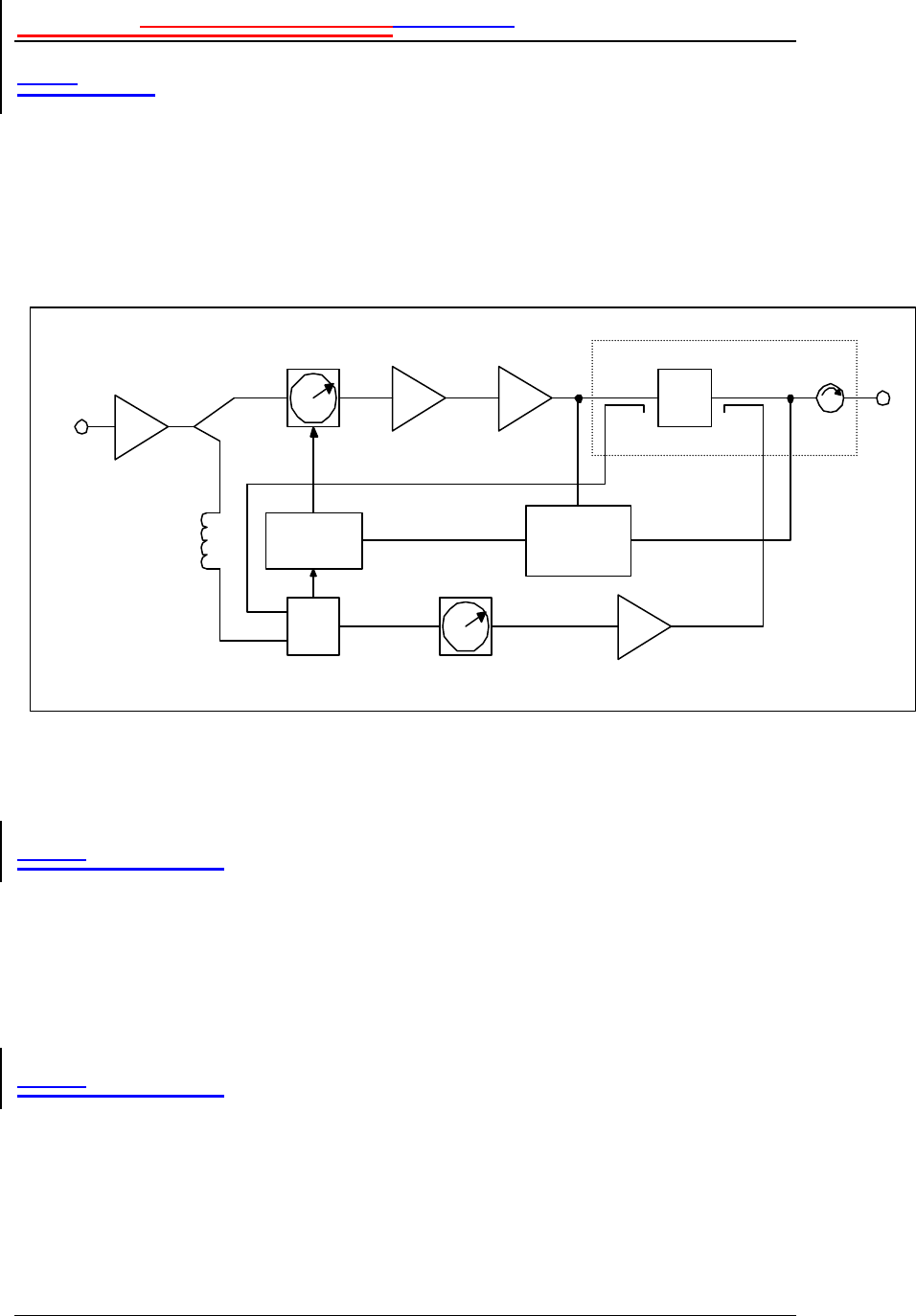
To achieve the high level of linearity required to support multiple cellular carriers
at the minimum cost, the RF modules in the MCPS2135 use a single loop feed-
forward correction architecture with two amplification paths – the main path,
containing the main amplifier, and the error path, containing the error amplifier.
The combination of these two paths in a feed forward loop configuration results in
a signal in which the distortion products have been cancelled, enabling highly
linear operation of the amplifier.
Figure 1: RF Module Functional Block Diagram
1.1.1.11.3.1.1 Main Loop
The output of the main amplifier contains both the desired signal and Inter-
modulation Distortion (IMD) products. This signal is coupled off and combined
with the undistorted input signal coupled off the preamplifier. The relative delay
and phases of these signals are adjusted so they combine to cancel out the desired
signal, creating an error signal composed of only the main amplifier IMD
products. The cancellation process is controlled by a Digital Signal Processor,
which insures optimum carrier cancellation over all environmental conditions.
1.1.1.21.3.1.2 Error Loop
The error signal is amplified in the error loop. The amplified error signal is then
combined with the output of the main amplifier containing both the desired signal
and distortion products such that the distortion products cancel. The error loop
provides the adjustments and controls necessary to assure that the amplitude,
phase and delay of both signals result in the desired cancellation.
Main
Vector Mod
Driver
Amp
Main
Amp Delay Filter
Output Module
Pilot
Generator /
Reciever
Cancellation
Controller
Carrier
Cancellation Error
Vector Mod
Σ
τ
Preamplifier
Delay
Line
Error
Amp
RF Input
RF Output
IntroductionPlanning and PreparationIntroduction
MCPS2135 System Operation 5
2001 Spectrian Corporation. All rights reserved.
1.1.1.31.3.1.3 Amplifier Management Unit
The Amplifier Management Unit (AMU) monitors and controls performance of
the various subassemblies within the RF module. The AMU provides operating
status information via front panel LEDs. Within a multi-module system, the AMU
provides status to the MCPS2135 AMM.
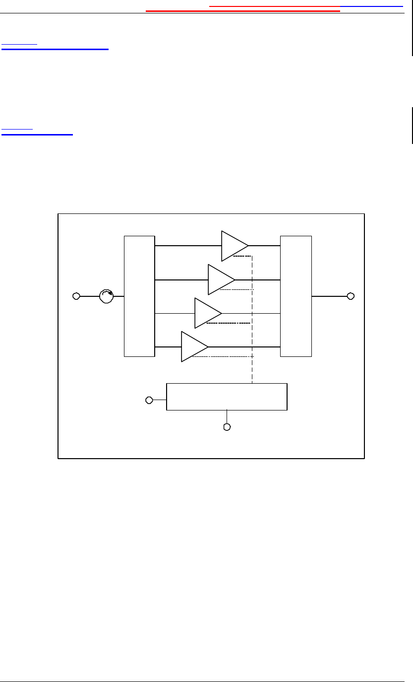
1.1.21.3.2 MCPS2135 Amplifier System
A fully-equipped MCPS2135 consists of a rack-mounted shelf containing up to
four RF modules. Multi-module systems contain an Alarm Management Module,
and an internal divider/ combiner. A block diagram of the system is shown in
Figure 2.
Figure 2 System Block Diagram
The standard MCPS2135 configurations are summarized in Table 1. Please
consult the factory or Spectrian sales for configurations not listed here.
2
÷÷
135 W MCPA
Modules
3
4
1
Alarm Management
Module
Splitter
Basestation Interface
RS-422 or RS-485
ΣΣ
Combiner
RF
Input RF
Output
Status Port
RS-232

IntroductionPlanning and PreparationIntroduction
6 MCPS2135 Operations Manual
2001 Spectrian Corporation. All rights reserved.
Power Dimensions
(W x D x H)
Comments
135W 5.25” x 18” x 14” Single module with communication interface
135W 19” x 18” x 3 RU Single module configuration in 19 in. housing
135W 23” x 18” x 3 RU Single module configuration in 23 in. housing
250W to 500 W 23” x 18” x 8 RU 2 to 4 modules combined
250W to 500 W 24” x 18” x 8 RU 2 to 4 modules combined 24 inch rack config
Table 1: MCPS2135 System Configurations
MCPA modules
The RF modules are ultra-linear amplifiers optimized for high power amplification
of cellular signals. Each RF module provides up to 135 Watts of RF output power.
Multi-module systems have combiner losses which reduce the output power of
each module to approximately 125 Watts. The RF module has been discussed in
section 1.2.1
Amplifier Management Module
The Amplifier Management Module (AMM) contains the system control and
alarm management logic and the interface to external operation and control
systems.
Divider/Combiner
The divider/combiner used in multi-module systems allows the RF modules to
function as a single system. The combiner has an active architecture, which
automatically reconfigures to minimize combining losses if an RF module should
fail.

Planning and PreparationPlanning and PreparationIntroduction
MCPS2135 System Operation 7
2001 Spectrian Corporation. All rights reserved.
2 Planning and Preparation
2.1 Installation Planning
It is important to ensure proper planning and site preparation is complete prior to
beginning the installation of the MCPS2135. The following sections describe
installation considerations and the information required before beginning the
installation procedure. Spectrian Applications Engineering is always available to
assist with planning for the installation of the MCPS2135.
1.22.2 Site Planning Guide
For each MCPS2135 cell site installation, there must be a Site Planning or Site
Engineering guide giving the detailed information on the site considerations, rack
installation, cable connections, and Radio Parameters.
. Note: Local building and fire codes govern the manner in which some site
preparation and installation tasks are performed. Spectrian recommends that
you consult your local building inspector or a licensed engineer to ensure that
the site installation conforms to local building codes.
2.2.1 Site Considerations
Intended Installations
The MCPS2135 system is intended for installation only in restricted access areas
(dedicated equipment rooms, equipment closets, environmental shelters, or the
like) in accordance with Articles 110-16, -17, and -18 of the National Electrical
Code, ANSI/NFPA No. 70.
Weight
The MCPS2135 shelf and each RF module weigh approximately 50 pounds (22.7
kg); the fully equipped system weighs 250 pounds (113.3 kg). The system must
be installed, using the appropriate mounting kit, into a rack capable of supporting
the unit, and located on a floor or surface capable of supporting the combined
weight of the rack, the MCPS2135, and the installer or technician.
Floor Covering
If you intend to use a floor covering under the MCPS2135, avoid combustible
materials , industrial carpeting, and materials that will permit generation of
electrostatic charges.
Illumination
The MCPS2135 is designed to be installed and serviced under normal workroom
lighting. During installation, room lighting must be bright enough to allow
reading instructions and inspection of modules, but not so bright as to interfere

Planning and PreparationPlanning and PreparationIntroduction
8 MCPS2135 Operations Manual
2001 Spectrian Corporation. All rights reserved.
with viewing the status LED indicators on the front panel. The MCPS2135 should
be oriented or shielded so that direct sunlight does not fall upon the front panel.
Fire Protection
Spectrian recommends that the MCPS2135 installation site be equipped with
smoke detectors and an automatic fire-extinguishing system. In addition, for
personnel safety, the site should be equipped with a portable halon or CO2 fire
extinguisher.
Altitude
When installing the MCPS2135 above 5000 ft (1542 m), derate the maximum
operating temperature by 2° C per 1000 ft (304 m) above 5000 ft.
Ventilation
The MCPS2135 requires unrestricted airflow around the MCPS2135. The site
must be ventilated or air-conditioned so that ambient air does not exceed 50°
Celsius (122° F).
Ambient air quality
The MCPS2135 should be installed in a location that is free of airborne dust and
toxic or corrosive fumes.
Vibration and Noise
The MCPS2135 tolerates moderate levels of vibration and ambient noise. The
MCPS2135 should not be installed in a location subject to mechanical shocks or
vibrations conducted from nearby mechanical equipment. The MCPS2135
generates fan noise below 65 dBa during operation and no additional acoustic
treatment of the site is needed.
Lightning Protection
Spectrian recommends that all power, RF, and signal lines that connect to the
MCPS2135 be protected by approved lightning arrestors. Your local fire or safety
codes will determine the type of lightning protection required.
Grounding
Spectrian recommends that the MCPS2135 and entire equipment rack be grounded
with an engineered grounding system, including a ground halo and ground rods.
1.1.22.2.2 Rack Installation Considerations
Rack Space
Multi-module MCPS2135 systems require 8U of rack space in a 23” or a 24” rack.
Optional mounting hardware for other rack sizes is also available. When used, the
optional preamplifier requires an additional 2U above the shelf. Single module
shelves require 3U of rack space.
Clearance
During operation, the MCPS2135 requires front cabinet clearance for unrestricted
cooling air input, plus a minimum of 4 inches (102mm) behind the MCPS2135 to
exhaust hot air. Some additional rear clearance is desirable to accommodate routing
the RF input and output cables and the DC power cables to their connections on the
rear of the unit.

Planning and PreparationPlanning and PreparationIntroduction
MCPS2135 System Operation 9
2001 Spectrian Corporation. All rights reserved.
1.1.32.2.3 Cable Connections
DC Power Supply
The MCPS2135 requires customer-supplied connections to the site +27 VDC
power supply. The MCPS2135 is normally connected to the power supply with a
separate connection for each RF module; a single connection to each shelf is also
possible using the optional shelf power bus. Table 2 shows the required current
and recommended power service for MCPS2135 systems with the indicated
number of active amplifier modules installed in a system shelf.
# RF
Modules RF Output
Power I(Max),
27 VDC Recommended Service
1 135W 55 Amps 2 wires (2/module), #6AWG, #10 lugs
1 ea. 60A Circuit Breaker
2 250W 110 Amps 4 wires (2/module), #6AWG, #10 lugs
2 ea. 60A Circuit Breaker
3 370W 165 Amps 6 wires (2/module), #6AWG, #10 lugs
3 ea. 60A Circuit Breaker
4 500W 220 Amps 8 wires (2/module), #6AWG, #10 lugs
4 ea. 60A Circuit Breaker
Table 3: Individual Power Connections to each RF Module
Single Bussed Connection
When using the bussed connection option, the service should be sized for a fully
equipped shelf. This will provide adequate service with capacity for future
expansion.
Recommended Service: 2 Wires, #2AWG, ¼”narrow tongue lug (T&B 55116 or
equivalent); 1 ea. 240A Circuit Breaker.
Chassis Ground Wire
The MCPS2135 shelf requires a customer-supplied chassis ground connection using
#8AWG with a ¼” ring lug .
RF Input and Output Cables
The MCPS2135 requires a single customer-supplied SMA male RF input cable
and a single customer-supplied male type-N RF output cable. The RF output cable
must be rated to properly handle the MCPS2135 output power. The female
connectors are on the rear of the MCPS2135 shelf. Spectrian offers optional RF
cables for use in connecting the MCPS2135 amplifier.
Alarm Interface Cables
The MCPS2135 requires customer-supplied interface cables to the system alarm
interfaces. The standard system has screw terminal connections to form C-relay
alarm contacts; optional RS 422 serial connections are also available. The alarm
connection options for the MCPS2135 are listed in Appendix A3.

Planning and PreparationPlanning and PreparationIntroduction
10 MCPS2135 Operations Manual
2001 Spectrian Corporation. All rights reserved.
Radio Parameters
To set up the MCPS2135, the installer must know the following radio parameters
for the MCPS2135 installation.
• Total Planned Output Power
• Number of CDMA Frequency Assignments and power of each FA
• Number of AMPS/TDMA/CDPD Channels and power of each channel
• Planned System Gain
Installation Equipment
Refer to the Tools and Materials listing in the following sections for the required
MCPS2135 installation and test supplies.
1.32.3 Determine the required RF input power
Before applying RF input power to the MCPS2135, determine the input drive level
and output power needed for each channel being amplified by using the RF Drive
Power Worksheet, shown below.
Once the required RF input power for each channel is determined, continue to the
next step, setting the RF input drive power.

Planning and PreparationPlanning and PreparationIntroduction
MCPS2135 System Operation 11
2001 Spectrian Corporation. All rights reserved.
RF Drive Power Worksheet
A) Total output power (POUT) required = W dBm
B) Determine total output required for each fully loaded
CDMA Frequency Assignment (FA):
# of FA’s =
total power per FA =
total CDMA power (PCDMA) =
Total available analog power (PAN ) =
(P
AN
= P
OUT
– P
CDMA
) W
D) Total # of analog channels, including setup (#ch) =
E) Maximum per channel analog output power (PAN/ch) =
(P
AN
/ch = P
AN
/# of channels) W dBm
F) System Gain (Gain) * = dB
G) Maximum composite input power (PIN) =
(P
IN
= P
OUT
in dBm – Gain in dB) dBm
H) Maximum per channel analog input power (PIN/ch ) =
(P
IN
/ch in dBm = P
AN
/ch in dBm – Gain in dB) dBm
* NOTE: Depends on configuration which is factory settable from 30 dB to 60 dB. On single
module systems, the gain may be adjusted by the end user with Spectrian’s Graphical User
Interface software. Consult with factory or Spectrian Sales for more information.
1.1.12.3.1 Set RF input drive power for each channel
∗ Caution: If the RF Input Cable is connected to the MCPS2135, disconnect it
from the MCPS2135. Connect the RF input cable to the Power Meter for the
following step.
∗ Caution: Make sure that the power to be measured with the meter does not
exceed the manufacturers recommended maximum input level.
Switch on the RF input drive power at the customer provided host system exciter
following the instructions supplied with your RF source equipment.
Set and verify the RF input drive level for each individual channel
1. Key-on each RF input channel individually.
2. Monitor the RF input using a HP436A or equivalent power meter.
3. Verify that the maximum input power for the channel does not exceed the
calculated levels on the RF Drive Power worksheet (line H).
4. Key off the channel and repeat for the remaining channels. Continue to
verify the required channel input power is not exceeded.

Planning and PreparationPlanning and PreparationIntroduction
12 MCPS2135 Operations Manual
2001 Spectrian Corporation. All rights reserved.
After verifying the power of each individual channel individually, ensure that the
total average input power remains less than or equal to the maximum rated
composite power calculated in (G) of the worksheet.
1. Key-on all channels at one time, including any CDMA F.A.s, and
measure input power.
2. If the average composite input power exceeds the calculated average
composite input power (line H), readjust all channels as necessary to
ensure average input power remains less than or equal to specifications.
Turn off all channels. The drive power is now set properly.
1.42.4 Prepare for Installation
Before beginning the installation, verify that all the necessary site and radio
information, installation materials, tools, and MCPS2135 equipment are on hand.
Correct any problems or omissions before continuing. Refer to the following
Receiving and Unpacking Procedure to prepare the MCPS2135 equipment.
1.1.12.4.1 Inventory Received Equipment
1. Upon receipt of the MCPS2135, remove the packing lists, installation kit, and
other documents attached to the shipping container.
2. Examine shipping documents to make certain that they agree with your copy
of the order. If there is a discrepancy between the order and the items or
quantity shipped, contact your Spectrian Customer Service representative
listed in Appendix A1 of this manual.
3. Check the packing list and verify that all necessary equipment has been
delivered, and that the parts are undamaged. If any evidence of shipping
damage is noted, notify the delivery agency before continuing.
∗ Caution: If the container or contents appear to be damaged, you must contact
the carrier without delay and file a damage claim. If shipping damage occurred,
the carrier may wish to have a claims agent present when the MCPS2135 is
unpacked and inspected. To protect your warranty rights, you must also notify
your Spectrian representative and advise that the MCPS2135 was damaged
during shipment.
2.4.2 Unpack Received Equipment
Uncrating, inspecting, and preparing the MCPS2135 for site installation will
require some tools and materials not included in the shipment. Use of the
following materials is suggested to perform these tasks.
. Note: Assemble all tools, materials, and safety equipment before beginning
work.
Safety Equipment
• Safety glasses

Planning and PreparationPlanning and PreparationIntroduction
MCPS2135 System Operation 13
2001 Spectrian Corporation. All rights reserved.
• Work gloves
• Steel-toe shoes
• Back-support belt
Tools
• Box knife
• Pair of large scis sors
• Inspection flashlight or lamp
• Pen or pencil
• Strap cutter
• Straight-blade screwdriver
Other Materials
• A copy of the Purchase Order
• A copy of the Packing List
Unpack equipment
1. Open the shipping container(s) and inspect the contents. Using the required
safety equipment and tools, carefully cut the metal and/or nylon straps that
surround the shipping containers. When using a box knife or scissors, take
care not to damage the contents of the box. Take care to avoid scratching the
cabinet finish.
2. Do not remove the ESD protective wrapping that surrounds the cabinet, unless
wearing an ESD protective wrist strap. If possible, remove this material by
unwrapping the MCPS2135 by hand, rather than cutting this material with
scissors or knives. Spectrian recommends not removing the protective
wrapping until installation.
3. Remove spacers, packing inserts, protective coverings, plastic bags, and other
shipping materials from the outside of the MCPS2135. Avoid using knives or
scissors to perform this task.
4. Carefully collect and dispose of the packing materials. Many of the packing
materials used by Spectrian are suitable for recycling and need not contribute
to landfills.
5. While inspecting the unpacked MCPS2135, compare the quantity and labeling
of each module with shipping documents and the purchase order. If there is
an unresolved discrepancy between the order and the items received, contact
your Spectrian representative.
6. Inspect the MCPS2135 exterior for evidence of shipping damage. Metal
surfaces should not be dented or scratched. Panels, handles, screws, and
indicators should appear undamaged and properly aligned. Connectors should
be tightly affixed to the cabinet, with no visible dents or distortion.
. Note: If you discover damage during inspection, contact the shipper and
Spectrian at once. The shipper will furnish instructions on how to document the
discovered damage. Spectrian will arrange to promptly ship replacement parts.

Planning and PreparationPlanning and PreparationIntroduction
14 MCPS2135 Operations Manual
2001 Spectrian Corporation. All rights reserved.
2.4.3 Repackaging for Return Shipment
If it is necessary to repackage the MCPS2135 for return shipment, contact
Spectrian Customer Service for detailed instructions. If possible, use the
original cartons and inserts to package equipment for return. Otherwise, use
suitable shipping cartons and foam inserts to prevent damage in transit.

MCPS2135 InstallationPlanning and PreparationIntroduction
MCPS2135 System Operation 15
2001 Spectrian Corporation. All rights reserved.
3 MCPS2135 Installation
3.1 Introduction
The following section describes how to install the MCPS2135 series amplifier in a
base station.
Each MCPS2135 system features rear-access RF input and output connectors, a
DC voltage input receptacle, and a front-access RS-232 status interface connector.
Additional optional features include a rear-access RS-422 serial interface
connector and a remote alarms interface connector. Specific connector pinout
information for your MCPS2135 configuration is provided in Appendix A3.
Please read and understand the instructions and warnings in this section and at the
beginning of this manual before handling or unpacking the MCPS2135 modules.
The MCPS2135 is designed to be installed by trained and qualified technicians.
+ Warning: Each MCPS2135 amplifier module and the shelf subassembly weigh
50 lbs (22.7 kgs); when crated for shipping an MCPS2135 system can weigh in
excess of 290 lbs (131.5 kgs) and be unbalanced. To avoid injuries or damage,
use care and obtain assistance when lifting a crate containing MCPS2135
components.
∗ Caution: Do not attempt to move an MCPS system with modules installed.
∗ Caution: Provide bottom support when removing an MCPA module to avoid
damage to the fan housing.
. Note: Local building and fire codes govern the manner in which some site
preparation and installation tasks are performed. Spectrian recommends that
you consult your local building inspector or a licensed engineer to ensure that
the site installation conforms to local building codes.
1.23.2 Task safety equipment, tools and materials
The following safety equipment, tools, and materials are recommended to perform
the installation tasks in this section.
Safety Equipment
• Safety glasses
• Work gloves
• Back-support belt
Tools
• Heat Gun (Master 10008 – MAS or equivalent)

MCPS2135 InstallationPlanning and PreparationIntroduction
16 MCPS2135 Operations Manual
2001 Spectrian Corporation. All rights reserved.
• Cable Cutter (Klein 63050)
• Flat and Phillips screwdrivers
• Adjustable wrench
• ESD protective wrist strap
• Inspection lamp or flashlight
• Crimping tool (T & B TBMS or equivalent)
• Digital Volt Meter (DVM)
• Torque Driver (Mountz TLS1360 or equivalent)
• Current Meter
• Wire Strippers (Greenlee 45109 or equivalent)
Materials
• Pressurized can of spray-on contact cleaner
• Rack-mounting hardware and fasteners
• DC Power, RF, and signal cables
• Crimp -on circular lugs
• 8 AWG insulated (green) copper ground wire
• Shrink Tubing
3.3 Rack Installation
The MCPS2135 series amplifiers mount in the equipment rack using rack-
mounted side support rails .
The MCPS2135 shelf subassemblies are labeled with the part and serial numbers,
using standard EIA part identification, date code, and serializing methods. It is
also labeled with the appropriate FCC approvals.
All MCPS2135 shelf subassemblies contain all internal wiring for DC power and
RF signal distribution to the RF modules and the interfaces to the cell site.
Brushless DC cooling fans are mounted on each RF module; cooling air is drawn
through grille openings in the front of each module and discharged through the
rear.
+ Warning: The MCPS2135 shelf sub-assembly weighs approximately 50 lbs
(22.7 kg). Use caution when lifting; obtain assistance if necessary.
3.3.1 Install Shelf Subassembly
1. Make certain that adequate vertical space within the rack enclosure is
available. Verify that there will be at least 4 inches (10cm) of space
behind the unit when installed for cooling air flow.
2. Put on an ESD protective wrist strap, and properly ground it.
3. Unpack the MCPS2135 side mounting rails and attachment hardware and
install them in the rack as shown on the accompanying job sheet.

MCPS2135 InstallationPlanning and PreparationIntroduction
MCPS2135 System Operation 17
2001 Spectrian Corporation. All rights reserved.
4. Unpack the MCPS2135 shelf and record its serial number. Ensure the
shelf is in the proper upright vertical orientation and slide it onto the
mounting rails.
5. Use the supplied mounting screws to attach the shelf to the rack. Tighten
rack mounting screws securely.
3.3.2 Install Modules in Shelf
1. Unpack each RF module. Align each module with the guides in an
amplifier slot and slide the module as far as possible into the shelf,
making sure the module is fully seated. Note that each module weighs
approximately 50 lbs (22.7 kg); get a helper to assist if necessary.
Tighten the fasteners at the bottom of each faceplate to lock the modules
in place.
2. Unpack and install the Amplifier Management Module (AMM) module
in the rightmost slot of the shelf. Tighten the fastener at the bottom of the
faceplate to lock the module in place.
3. Inspect the alignment of the finished installation, and adjust if needed. If
no problems are found, rack installation is complete.
3.4 Cable and Wire Connections
3.4.1 Connect Chassis Ground Wire
1. Locate the chassis ground stud on the rear of the MCPS2135 for ground
wire attachment.
2. Measure the distance and routing between the MCPS2135 ground stud
and an attachment point to earth ground. Cut a length of #8 AWG
insulated (green) solid copper wire sufficient for the connection.
3. Crimp a ¼” circular lug to one end of the ground wire.
4. Remove the nut and lock washer on the MCPS2135 ground stud. Attach
the DC ground wire lug to the grounding stud on the MCPS2135, and
replace the lock washer and nut. Tighten the nut securely.
5. Connect the other end of the ground wire to the appropriate earth ground.
6. Use a DVM to verify that the resistance between the chassis ground and
true earth ground is less than 100 Ohms.
7. Inspect the finished connection. If no problems are discovered, ground
wire installation is complete.
3.4.2 Connect DC Input Power Cables
The MCPS2135 power connection can be made using a pair of wires for each RF
module, or via a single bussed connection. The DC input voltage cabling must be
terminated by crimped lugs and sized to the correct wire gauge to accommodate
the wire length and the DC current requirements of the MCPS2135 in accordance

MCPS2135 InstallationPlanning and PreparationIntroduction
18 MCPS2135 Operations Manual
2001 Spectrian Corporation. All rights reserved.
with local building codes and industry practice. Refer to Table 2 for the
recommended power supply circuit and wire sizing for each option.
+ WARNING: Do not perform DC lead installation with energized leads. Ensure
that the DC power supply is OFF for all installation activities!
1. Locate the positive and negative terminals on the customer-provided DC
power source, and verify polarity with a DVM.
2. Locate the power supply lugs at the top of the rear of the shelf
subassembly. The four #10 lugs are for the per-RF-Module connection
option, the single pair of ¼” lugs are for the bussed power option.
Determine which set of lugs will be used for this installation.
3. Measure the distance and routing between the power source and the
MCPS2135 DC lugs.
4. For each power connection being made, cut equal lengths of wire for
power and return. Strip and connect each wire to the appropriate power
connection, using the crimping tool and the supplied ground lug.
∗ Caution: Verify the polarity of each supply wire prior to connecting them to the
shelf subassembly. A reversed-polarity connection will severely damage the
MCPS2135 and will void the product warranty.
5. Crimp the appropriate terminal lugs onto each power supply wire.
6. Attach one positive supply wire and one return wire to each of the four
sets the power supply lugs at the top of the rear of the shelf subassembly.
Tighten the attachment nuts firmly.
7. Inspect the finished connection. If no problems exist, the DC input power
cable installation is complete.
3.4.3 Connect RF Output and Input Cables
The MCPS2135 has one female type-N amplified RF output for connection to a
customer-supplied coaxial cable terminated with a male connector, and one female
SMA RF input for connection to an customer-supplied input cable terminated with
a male SMA connector.
+ WARNING: Do not perform RF cable installation with DC power applied to the
MCPS2135. Ensure that the input DC power supply is OFF before handling RF
cables.
∗ Caution: The Output cable must be connected before connecting the Input
cable.
. Note: The integrity of RF cabling is critical to the electrical performance of the
MCPS2135. Ensure connectors are properly assembled, are free of debris, and
are clean.
1. Locate the male N-type RF output connector on the end of the coaxial
cable attached to the output load. Inspect the connector and clean if
necessary; fix any problems with the cable or connector before
proceeding.

MCPS2135 InstallationPlanning and PreparationIntroduction
MCPS2135 System Operation 19
2001 Spectrian Corporation. All rights reserved.
2. Locate the female N-type RF connector labeled “RF OUTPUT” on the
MCPS2135.
3. Screw the male cable connector firmly onto the female RF output
connector of the MCPS2135.
4. Locate the male input RF connector on the end of the coaxial cable from
the RF signal source. Inspect the connector for damage or irregularity,
and fix any problems with the cable or connector before proceeding.
5. Locate the female SMA connector labeled “RF INPUT” on the rear of the
MCPS2135.
6. Screw the male cable connector firmly onto the MCPS2135 female
connector.
3.4.4 Connect Alarm Interface Cables
1. The MCPS2135 provides optional factory-configured connections for dry
contact, TTL, or RS-422 communications and alarm output to the
customer system. Refer to the connector pin-out and descriptions in
Appendix A3for the connections applicable to your MCPS2135.
2. Locate the interface connectors located on the rear of the shelf
subassembly behind the Amplifier Management Module (AMM). Inspect
the connector and clean if necessary; correct any problems with the cable
or connector before proceeding.
3. Connect the male connector or input wires to the connector mounted on
the MCPS2135. Tighten the two screws on the cable connector (if any)
firmly.
3.5 Completing the Installation
3.5.1 Set the MCPS2135 unit address
Each MCPS2135 may be configured with a unique address (0 – 7) for commands
and status reports sent through the RS-422 port.
If this option is included in the MCPS2135, locate the rotary switch on the rear of
the MCPS2135 Amplifier Management Module. Set the switch to the desired
address.
1.1.23.5.2 Verify Installation
Recheck all physical and electrical connections to the MCPS2135 and remedy any
problems discovered.
Once the installation is verified, the MCPS2135 is ready to be set up and placed in
service, as described in the next section.

System Start-UpPlanning and PreparationIntroduction
20 MCPS2135 Operations Manual
2001 Spectrian Corporation. All rights reserved.
4 System Start-Up
4.1 Introduction
This section contains instructions on powering up the MCPS2135 amplifier
system. These procedures should be followed after installing the MCPS2135
amplifier system in the rack.
1.24.2 Safety Information and Tools
To avoid injury, installers, technicians, and maintenance personnel must follow
Spectrian's recommended procedures and observe safety precautions.
+ Warning: The MCPS2135 should only be operated by trained and qualified
personnel. Always follow safety warnings.
+ Warning: Persons with cardiac pacemakers should avoid exposure to RF
radiating elements. Exposing the human eye to high levels of radio-frequency
radiation may result in the formation of cataracts. Do not operate exposed
circuitry or radiating elements with personnel in close proximity to the radiating
source. Always replace covers and shields during operation.
. Note: Before shipment, the MCPS2135 was inspected and found free of
mechanical and electrical defects. The electrical performance of the MCPS2135
should be verified using these procedures. If there is any deficiency, or if
electrical performance is not within specifications, notify your Spectrian
representative immediately.
Tools
The following tools are recommended to perform installation tasks.
• HP 436 Power meter
• Digital Volt Meter (DVM)
4.3 Verify system installation
Before operating the MCPS2135, verify proper installation as described in the
previous section.
1. Verify that there are no obstructions to airflow in the front or rear of the
MCPS2135.
2. Ensure that the DC power supply at the site is functioning normally. DO
NOT turn on the DC supply to the MCPS2135 at this time.
3. Ensure that the MCPS2135 is physically connected to an input RF signal
source and terminated in an output load. Ensure that the RF signal level has
been set properly. DO NOT turn on the RF signal source at this time.

System Start-UpPlanning and PreparationIntroduction
MCPS2135 System Operation 21
2001 Spectrian Corporation. All rights reserved.
4. If used, verify that the MCPS2135 address is set correctly.
+ WARNING: The RF output of the MCPS2135 should be connected to a 50-ohm
load before DC power is turned on. The load must be capable of dissipating at
least 500 watts average power and 6,300 watts of peak power.
After mechanical and electrical installation tasks are complete, the MCPS2135 is
ready for power-on check.
1.44.4 Power Up the MCPS2135
∗ Caution: Read and understand all of the following steps before taking any
action.
. Note: The MCPS2135 should be powered on and enabled before the RF input
power is applied.
1. Switch on the DC input power to the MCPS2135. Measure the input
voltage at the bus bar connections at the rear of the unit and verify it is
27VDC. Adjust the power supply if necessary.
Following the power-up self-test, the MCPS2135 AMM POWER LED
should be GREEN, indicating that the unit is functional and that in input
voltage is between 24 and 28 VDC. If the POWER LED is amber, red, or
does not light, turn off the DC input power and correct the power supply
fault.
The ENABLE switch should be “ON”. The MCPS2135 RF modules will
automatically be ENABLED. All four LEDs on each MCPA module
should be GREEN.
To DISABLE an RF module, set the front panel ENABLE/DISABLE
switch to DISABLE; the ENABLE LED will then be RED.
2. Wait 5 minutes for the MCPS2135 to reach a stable operating temperature
and to charge the real-time clock backup power. DO NOT apply
commercial traffic signal power during this time.
3. If the MCPS2135 is connected to a remote operations center via one of
the rear panel interface connections, verify no alarms have been reported.
4. Verify that all MCPS2135 status LED indicators remain GREEN.
5. If any LED indicators are AMBER or RED, then RF modules are
disabled or there is a problem which must be remedied before continuing.
Refer to section 6, Troubleshooting.
∗ Caution: Before applying RF input power to the MCPS2135, verify that the
applied RF input power for a single channel and the sum of all channels is
below the calculated maximum rated RF input.

MCPS2135 System MonitoringPlanning and PreparationIntroduction
22 MCPS2135 Operations Manual
2001 Spectrian Corporation. All rights reserved.
5 MCPS2135 System Monitoring
5.1 Introduction
This section describes methods for monitoring the MCPS2135 amplifier system
operation.
1.25.2 Monitoring the MCPS2135 System Operation
The MCPS2135 Amplifier Management Module (AMM) has a front panel RS-232
status port. This port provides the option to monitor the operation and status of the
MCPS2135 using a laptop computer, if desired.
A LabView-based Graphical User Interface (GUI), which can run on
Windows95, 98, or NT4.0-based laptop computers is available from Spectrian.
1.35.3 Alarm Definitions
Fault management may be accomplished by various means with the MCPS2135.
The MCPS2135 includes alarm LEDs, an RS-232 diagnostics port, and an optional
base station status/alarm interface. These LEDs may be used for visual
diagnostics by on-site technicians. Refer to Section 5 for details on the
MCPS2135 alarm and protection circuits.
1.1.15.3.1 Alarm classification
The MCPS2135 fault management subsystem classifies faults into three
categories. In order of escalation, these are minor faults, major faults, and critical
faults.
1.1.1.15.3.1.1 Minor Alarm
A minor problem exists, but the fault does not require a module to be taken out of
service.
Routine service attention is recommended.
1.1.1.25.3.1.2 Major Alarm
A major problem exists such that the MCPS2135 is not meeting all performance
specifications, but the unit is not automatically disabled.
Urgent service attention is required or the unit may take itself out of service.

MCPS2135 System MonitoringPlanning and PreparationIntroduction
MCPS2135 System Operation 23
2001 Spectrian Corporation. All rights reserved.
1.1.1.35.3.1.3 Critical Alarm
A major failure or a condition exists that could result in damage. The MCPS2135
is automatically taken out of service.
Immediate service attention is required.
1.1.25.3.2 Alarm Responses
The fault management system automatically responds when a fault is detected.
Responses vary in impact from alarm notification with no subsequent action (for
minor faults) to alarm notification and shut-down (for critical faults). The
hierarchy of responses is designed to keep the MCPS2135 in operation unless
continued operation would result in damage to the unit. Under some fault
conditions, the MCPS2135 continues to operate in a degraded state. The operator
may choose to continue to operate in a degraded state, shed channels, or shut down
the MCPS2135 until repairs can be completed.
1.1.1.15.3.2.1 Automatic Alarm resets
Critical Alarm
When a critical alarm occurs, the MCPS2135 will automatically be DISABLED
(i.e., taken out of service) until the operator re-ENABLES the unit.
Major Alarm
When a major fault is detected, the MCPS2135 attempts to clear the fault by
performing a reset. In most cases, the MCPS2135 will attempt to reset five times.
If the alarm condition fails to clear after five attempts, the MCPS2135 remains in
operation with the fault alarm set.
In the case of an over-temperature major alarm, the fault manager will attempt to
clear the alarm one time only by resetting. If the fault condition does not clear, the
alarm classification will escalate to critical (out-of-service), and the MCPS2135
will shut down and remain off-line until returned to service by the operator.
Alarm Transient Supression
To minimize false alarms from transient anomalies, the fault management system
is designed with built-in hysteresis and filtering. If the fault condition persists past
the filter interval, the appropriate fault alarm is set.
1.1.1.25.3.2.2 Manual Alarm resets
When a major Alarm is detected, the operator may choose from the following
options:
• Take no action and allow the MCPS2135 to operate in a degraded state until
service can be performed.
• Shed input channels to reduce the power to the MCPS2135.
• Disable the RF Module using the front panel switch, diagnostic port, or
optional base station alarm and control interface

MCPS2135 System MonitoringPlanning and PreparationIntroduction
24 MCPS2135 Operations Manual
2001 Spectrian Corporation. All rights reserved.
1.45.4 MCPS2135 Alarm Limits and Protection Circuits
The MCPS2135 series of multicarrier power amplifiers has a wide range of alarm
configurations available. These may be specified to meet the demands of specific
applications. In addition, the MCPA modules have built-in protection circuits to
prevent damage from unintentional misuse. Module alarms may be summarized
and reported to a BTS using a customized interface. This hierarchical system
insures that Spectrian’s MCPS2135 series amplifier systems remain robust with a
minimum of false alarms, but promptly report any real issues to the base station
controller.
The default alarm limit settings and analog protection circuit operation for the
MCPS2135 family of MCPA amplifier systems are summarized below. The
information contained herein is provided for reference only. Guaranteed
specification limits must be negotiated between prospective customers and
Spectrian. There are three levels of the alarm/protection hierarchy:
• Analog Protection Circuits – Configured in hardware design to protect the
MCPA.
• MCPA Module Alarms – Most are software configurable for specific
applications.
• Amplifier System Alarms – Summarizes MCPA and Alarm Management
Module status.
In general, analog protection circuit limits are set by design, and may not be
changed. MCPA alarm limits are software configurable, and may be tailored to
meet customer alarm specifications. Individual MCPA alarms are not displayed
on the module front panel, but they are accessible through Spectrian’s Graphical
User Interface (GUI) software. System level alarms are summaries of the module
alarm status (minor/major/critical), as well as the Amplifier Management Module
(AMM) and the communication link between the modules and the AMM. The
summary set-up is configurable using the amplifier GUI software.
1.1.15.4.1 MCPA Module Analog Protection Circuits
The MCPS2135 MCPA module design incorporates circuits to prevent MCPA
module damage by common misuse conditions. The circuits react automatically to
the conditions shown in Table 3 with the limits set as noted. These limits are not
adjustable by software configuration.
Control Condition Speed Latch
Input Overdrive > 10 dBm @ Input (configured for 57 dB module gain) 2 msec No
Main Amp Overdrive > 4 dBm @ Vectormod Input 35 µsec No
Error Amp Overdrive > -7 dBm @ Vectormod Input 35 µsec No
Overvoltage Clamp Internal DC line is limited to 28V by linear regulation
up to 30V input 10 msec No
Circuit Breaker > 75 A current draw 25 msec Yes
Table 3: Analog Protection Circuit

MCPS2135 System MonitoringPlanning and PreparationIntroduction
MCPS2135 System Operation 25
2001 Spectrian Corporation. All rights reserved.
1.1.25.4.2 MCPA Module Alarms
The set points, delay, reset points, and latching conditions of all three types of
alarms are software configurable. Some Minor alarm settings can be specified by
the customer but must be agreed upon between the customer and Spectrian prior to
installation or modification. Alarm limits for Major and Critical Alarms are fixed
and can not be modified, insuring long term reliability of the MCPA module.
Type Indicator Condition Action / Response
No Alarm LED Green Normal operation None
Minor LED Amber System functional but with degraded performance None
Major LED Red System malfunctioning but operating (degraded
performance) System Reset after Dwell
Critical LED Red Continuous operation may induce damage System Shutdown after Dwell
Table 4: Module Alarm Hierarchy
Description GUI
Mne-
monic
Minor
Alarm Set
Point
Major
Alarm Set
Point
Critical Alarm
(Module
Shutdown)
Critical
Alarm
Dwell
Time
Critical
Alarm
Latch
Hyst-
eresis
Reset
Point
Inlet Temperature TMP > 50 °C > 70 °C > 70 °C 10 min. No 50 °C
Main Amp Base
Temp TMP N/A > 90 °C > 90 °C, >120 °C,
no dwell 10 min. No 70 °C
Error Amp Base
Temp TMP N/A > 90 °C > 90 °C, >120 °C,
no dwell 10 min. No 70 °C
PCM Base Temp TMP N/A > 90 °C > 90 °C, > 120 °C,
no dwell 10 min. No 70 °C
Over/Under Voltage OVS/
UVS 22 to 24V
20 to 22V or
28 to 30V <20V or >30V 5 sec No 24V or
28V
IM Degradation LOP Loop 2
SNR < 0 dB VMOD at
rail N/A N/A No N/A
Load VSWR VSR >4:1 >10:1 N/A N/A No N/A
RF Overdrive OPR >150W >170W >170W 2 sec Yes 150W
Fan Failure FAN Low RPM
(≤50%
rated)
1 Fan
Failed 2 Fans Failed None No N/A
+8V DC-DC
Converter OVS/
UVS N/A <7V, >9V <7V, >9V 2 sec Yes N/A
+16V DC-DC
Converter OVS/
UVS N/A <14V, >18V <14V, >18V 2 sec. Yes N/A
-16V DC-DC
Converter OVS/
UVS N/A -18V, >-14V
-18V, >-14V 2 sec. Yes N/A
Input Current CKT N/A >60A >60A No Delay After 3
Failures N/A
BPM Power Cell
Failure STK 1 Power
Cell Failure 2 Power
Cell Failure > 2 Power Cell
Failure No Delay Yes N/A
Gain Drop GAN N/A < -3 dB N/A 2 sec. No < -1 dB
Table 5: Default Alarm Descriptions and Settings

MCPS2135 System MonitoringPlanning and PreparationIntroduction
26 MCPS2135 Operations Manual
2001 Spectrian Corporation. All rights reserved.
1.1.35.4.3 MCPA System Alarms
A multimodule MCPA system will have an Amplifier Management Module
(AMM) that summarizes the status of all modules and reports this information to
the base transceiver station (BTS). The format of this information is usually
customized for specific customers. Options for physical layer customization
include:
• Parallel TTL Interface – Summary bits for individual module status.
• Serial Interface (RS-232, RS-422) – Customized strings sent to BTS interface.
• Form-C Relay Contacts – Wired directly into BTS.
Messaging layer customization is usually specified by the customer. In addition
Spectrian does maintain an internal standard for serial messaging. System status is
generally a combination of the module status. This is also specified by the
customer. An example of a system alarm hierarchy might be as noted in the table
below.
MCPA Alarm
Condition Amplifier System Status Summary Logic
Minor At least one module reporting a minor alarm OR
Major At least one module reporting a major alarm OR
Critical At least 3 modules reporting a critical alarm AND
Table 6: Typical MCPS System Alarm Hierarchy

Troubleshooting and MaintenancePlanning and PreparationIntroduction
MCPS2135 System Operation 27
2001 Spectrian Corporation. All rights reserved.
6 Troubleshooting and
Maintenance
6.1 Introduction
The following chapter provides basic information about diagnosis of problems
with the MCPS2135. Please read the following safety information prior to
beginning diagnosis and repair actions.
+ Warning: Troubleshooting and repairs should be performed only by trained and
qualified personnel or at authorized Spectrian repair depots. Observe all safety
warnings and use the required safety equipment when performing the tasks
described in this chapter.
. Note: Before shipment, theMCPS2135 was inspected and found free of
mechanical and electrical defects. The electrical performance of theMCPS2135
should be verified using these procedures. If there is any deficiency, or if
electrical performance is not within specifications, notify your Spectrian
representative immediately.
Tools
The following tools are recommended to perform system service tasks.
• HP 436 Power Meter
• Digital Volt Meter (DVM)
6.1.1 Safety Information
To avoid injury, installers, technicians, and maintenance personnel must follow
Spectrian's recommended procedures and observe all safety precautions.
+ Warning: The MCPS2135 transmits high power at radio frequencies. Severe
radiation burns can occur if recommended safety precautions are not strictly
observed.
+ Warning: Persons with cardiac pacemakers should avoid exposure to RF
radiating elements. Exposing the human eye to high levels of radio-frequency
radiation may result in the formation of cataracts. Do not operate exposed
circuitry or radiating elements with personnel in close proximity to the radiating
source. Always replace covers and shields during operation.
+ Warning: Except where specifically indicated, always disconnect RF input
power and DC input power to the MCPS2135 before performing procedures that
do not require power. For those procedures that do require power, be extremely
Troubleshooting and MaintenancePlanning and PreparationIntroduction
28 MCPS2135 Operations Manual
2001 Spectrian Corporation. All rights reserved.
cautious in handling test leads, tools, and equipment near live circuits. Never
reach into an enclosure for the purpose of servicing or adjusting live equipment.
6.2 Troubleshooting
Refer to section 5.3 for a definition of alarm types and the significance of those
alarm types.
1.1.16.2.1 Using LED Indicators
Each MCPS2135 RF Module is equipped with four LED indicators mounted on
the front panel. The system Alarm Management Module has two LED indictors
mounted on the front panel. These indicators provide useful status and diagnostic
information to operators and technicians.
Module
LEDs Green Amber Red
POWER Voltage OK, 26 VDC 22-24 V or 28-29V; RF
has degraded performance <22 V or >29V; RF
shuts down
ENABLED Enabled N/A Disabled
STATUS OK Minor Alarm Major or Critical
Alarm
FAN OK N/A Fan Failure
AMM LEDs Green Amber Red
DC POWER Voltage OK, 26 VDC 22-24 V or 28-29V;
system has degraded
performance
<22 V or >29V;
system shuts down
STATUS No Faults N/A System Fault Exists
1.1.26.2.2 Using the Diagnostic Port Output
Use of the Diagnostic Port is described in the release notes with the interface
software distribution.
1.1.36.2.3 Using Remote Alarm Monitoring
The MCPS2135 can include an optional alarm or control interface to base station
monitoring systems. These systems provide a serial interface to transmit status
codes to a remote host computer and receive a limited set of commands from the
host. For systems with such an interface, the interface is described in detail in the
specifications Appendix, A3.
. Note: The MCPS2135 fault management system and its associated alarms and
fault indicators operate independently of the serial interface.

Troubleshooting and MaintenancePlanning and PreparationIntroduction
MCPS2135 System Operation 29
2001 Spectrian Corporation. All rights reserved.
6.3 Periodic Maintenance
6.3.1 Dust Removal
Keep the air inputs and outputs of the MCPS2135 free of dust or other material
that could block cooling airflow.
1.1.26.3.2 Visual Inspection
Periodically visually inspect the MCPS2135 to ensure that all indicators are
functioning normally and that all system interfaces are properly connected.
1.46.4 Module Replacement
The RF modules of the MCPS2135 are hot-swappable field replaceable units
which can be removed and inserted while the system is online without affecting
the operation of the other units in the system.
1.1.16.4.1 Replacing an RF Module
+ WARNING: The RF Module is very heavy, 50 lbs (22.7 kg). Get assistance if
necessary.
∗ Caution: Provide bottom support when removing an MCPA module to avoid
damage to the fan housing.
1. Disable the RF Module being replaced by switching the front panel switch to
DISABLE. The ENABLE LED will be RED.
2. Undo the RF Module front panel fastener.
3. Slide the RF Module out of the shelf subassembly.
4. Place the RF module in a safe, static-free location.
5. Set the ENABLE switch on the replacement module to the DISABLE
position.
6. Insert the replacement RF Module.
7. Fasten the RF Module front panel fastener.
8. Set the ENABLE switch on the replacement module to the ENABLE position.
9. The RF Module will automatically self-test and then ENABLE; the ENABLE
LED will then be GREEN.
6.4.2 Replacing an AMM
1. Turn off the DC power to the MCPS2135.
2. Undo the AMM front panel fasteners.
3. Slide the AMM module out of the shelf subassembly.
4. Place the AMM in a safe, static-free location.

Troubleshooting and MaintenancePlanning and PreparationIntroduction
30 MCPS2135 Operations Manual
2001 Spectrian Corporation. All rights reserved.
5. Slide the new AMM into the shelf sub-assembly.
6. Fasten the AMM front panel fastener.
7. Turn on the DC power to the MCPS2135. The system will perform a power-
up self-test automatically.
8. The POWER LED will be GREEN.
6.4.3 Replacing shelf subassembly
+ Warning: Turn off the DC voltage and RF power prior to replacing an
MCPS2135.
+ Warning: Remove all DC and RF connectors prior to removing the MCPS2135
from the rack.
∗ Caution: Do not attempt to move an MCPS system with modules installed.
1. Remove the RF Modules’ front panel retaining screws.
2. Remove the RF modules from the rack.
+ WARNING: The RF Module is very heavy (50 lbs / 22.7 kg). Get assistance if
necessary.
3. Set each RF Module aside in a clean, safe place, free of electrostatic charges.
4. Remove the rack retaining screws. Grasp the front panel with both hands and
pull the MCPS2135 straight out from the rack.
5. Set the disconnected MCPS2135 aside in a clean, safe place, free of
electrostatic charges.
6. Remove the replacement MCPS2135 from its static-protective packaging.
. Note: You may wish to record the serial number on your repair record before
installing the module.
7. Follow the installation and operation instructions in Sections 3 and 4 to place
the unit back in service.
6.5 Module Service
6.5.1 Replacing MCPS2135 Fan Modules
+ WARNING: The RF Module is very heavy (50 lbs / 22.7 kg). Get assistance if
necessary.
∗ Caution: Provide bottom support when removing an MCPA module to avoid
damage to the fan housing.
1. Disable the RF module with the failed fan.
2. Remove the RF module with the failed fan from the rack.
3. Place the RF module on a clean, static-free work surface.

Troubleshooting and MaintenancePlanning and PreparationIntroduction
MCPS2135 System Operation 31
2001 Spectrian Corporation. All rights reserved.
4. Remove the screws securing the fan module to the RF module.
5. Disconnect the wiring harness from the fan module.
6. Connect the harness to the new fan module.
7. Replace the fan module and replace the attachment screws.
8. Replace the RF module in the rack.
9. Enable the module. Following the automatic power-up reset sequence, the
FAN indicator LED should be GREEN.

Appendix A1 Spectrian, Inc. OfficesPlanning and PreparationIntroduction
32 MCPS2135 Operations Manual
2001 Spectrian Corporation. All rights reserved.
Appendix A1 Spectrian, Inc.
Offices
Spectrian Headquarters
350 West Java Drive
Sunnyvale, Calif. 94089
Ph: 408-745-5400
Fax: 408-541-0263
Web: www.spectrian.com
Spectrian, Asia Office
4TH FL., Ensung Building,
601-18, Yoksam-Dong, Kangnam-Ku,
Seoul, 135-080, Korea
Ph: 822-545-6441
Fax: 822-545-6062
Centralized customer service:
For customer service support please direct all requests, questions, comments, and
inquires to cs@spectrian.com or mail to:
Spectrian Customer Service Department
350 West Java Drive
Sunnyvale, Calif. 94089
Ph: 800-793-7222
Fax: 408-541-0263
Technical Support Line
Ph: 408-745-5416

Appendix A2 Major Electrical SpecificationsPlanning and
PreparationIntroduction
MCPS2135 System Operation 33
2001 Spectrian Corporation. All rights reserved.
Appendix A2 Major Electrical
Specifications
Major Equipment Specifications for the MCPS2135 Amplifier System
Electrical Specifications Specification @ 25ºC
Frequency Range 869 - 894 MHz
Average Power¹ into 50 Ohms 135W (51.3 dBm) to 500W (57.0 dBm)
Intermodulation Distortion (IMD) -65 dBc with AMPS and/or TDMA IS-136, or IS-
97 CDMA dual mode input sources under nominal
conditions
CDMA Adjacent Channel Power2 < -45 dBc, 750 KHz offset, 30 KHz res bandwidth
@ 881 MHz, 100W Output < -60 dBc, 1.98 MHz offset, 30 KHz res bandwidth
Receive Band Noise 60 dBc
Carrier Spacing (AMPS/TDMA) 60 KHz min., 25 MHz max.
Power Output Stability for Single Frequency ± 0.5 dB under nominal conditions
Operating Bandwidth up to 25 MHz
Gain Factory set, 30 to 60 dB, 85 dB with optional
preamp
Gain Flatness vs. Frequency ± 0.5 dB (over all temps)
Gain Variation over Temp @ Any Inband Frequency ± 1 dB
Forward Power Sample Port Coupling -50 dB typ.
Input/Output Port Return Loss -15 dB min.
Second/Third and Greater Harmonic Output -50 dBc / -70 dBc
DC Input Voltage Range 26 to 28VDC
DC Input Current @ 27VDC 135W single RF module – 55A
250W two RF modules – 110A
370W three RF modules –165A
500W four RF modules – 220A
1Power levels at the output of the system combiner will vary depending on the configuration.
2Measured at the RF module output connector and in accordance with IS-97.

Appendix A3 Major Mechanical SpecificationsPlanning and
PreparationIntroduction
34 MCPS2135 Operations Manual
2001 Spectrian Corporation. All rights reserved.
Appendix A3 Major Mechanical
Specifications
Mechanical Specifications
Operating/Storage Temperatures 0ºC to 50ºC/-40ºC to 85ºC
Size, 4 module shelf (D x W x H)
(Excludes mounting ears and handles). 17.72 x 21.56 x 13.97 in. max
(450 x 547.62 x 354.84 mm max.)
Size, 1 module shelf 17.72 x 17.0 x 5.25 in. max
(Excludes mounting ears and handles). (450 x 431.72 x 133.33 mm max.)
Weight, 4 module shelf (Empty) Installed: approx. 45 lbs (20 kg)
Shipping: approx. 60 lbs max. (27 kg)
Weight, 1 module shelf (Empty) Installed: approx. 22 lbs (9 kg)
Shipping: approx. 29 lbs max. (13 kg)
Weight, 1 module Installed: approx. 50 lbs max. (22.7 kg)
Shipping: approx. 65 lbs max. (29.5 kg)
Connectors RF Input(s): SMA (F)
RF Output(s): N (F)
RF Output Sample Port: SMA (F)
DC Inputs: 10-32 and ¼-20 threaded lugs
DC Ground: ¼-20 threaded lugs
Maintenance Port: RS232
Alarms Port: RS422 (standard)
RS232 (Front panel port) pinout: Pin 1 GND
Pin 2 TX
Pin 3 RX
Pin 4 N/C
Pin 5 GND
Pin 6 N/C
Pin 7 RTS
Pin 8 CTS
Pin 9 N/C
Indicators AMM: DC On, Alarm LEDs
MCPA Modules: DC On, Enable, Alarm, Fan
LEDs
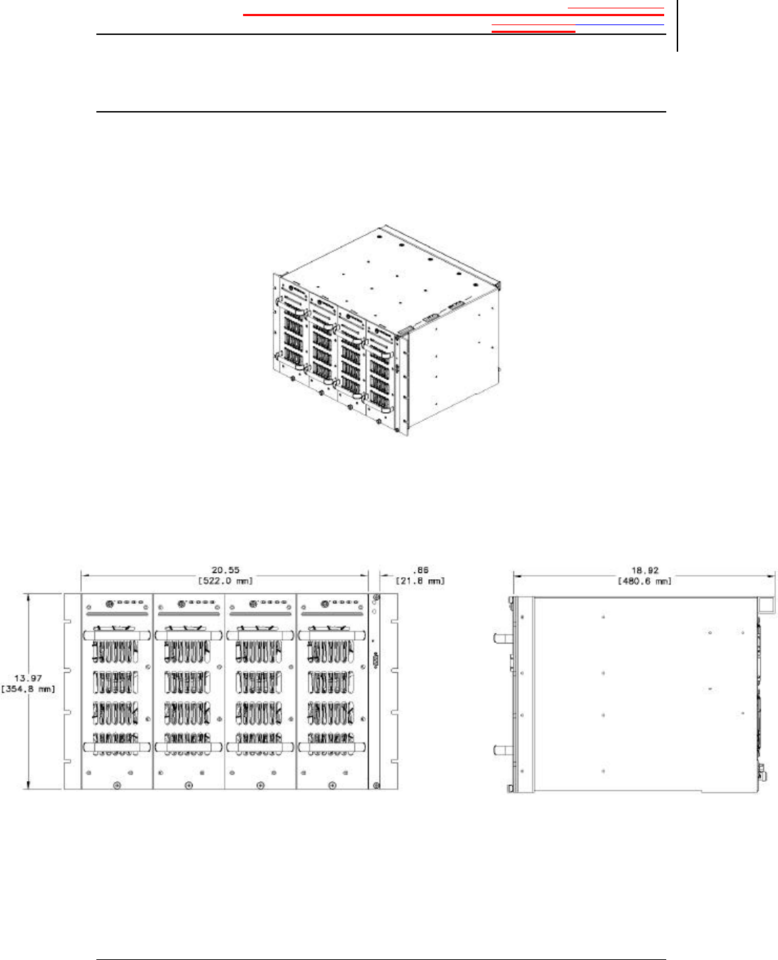
Appendix A3 Major Mechanical SpecificationsPlanning and
PreparationIntroduction
MCPS2135 System Operation 35
2001 Spectrian Corporation. All rights reserved.
Mechanical Outlines
MCPS2135 500W
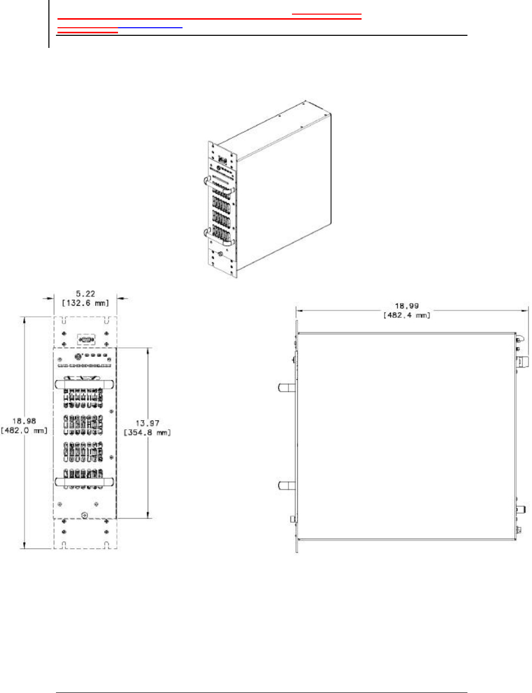
Appendix A3 Major Mechanical SpecificationsPlanning and
PreparationIntroduction
36 MCPS2135 Operations Manual
2001 Spectrian Corporation. All rights reserved.
MCPS2135 135W Configuration
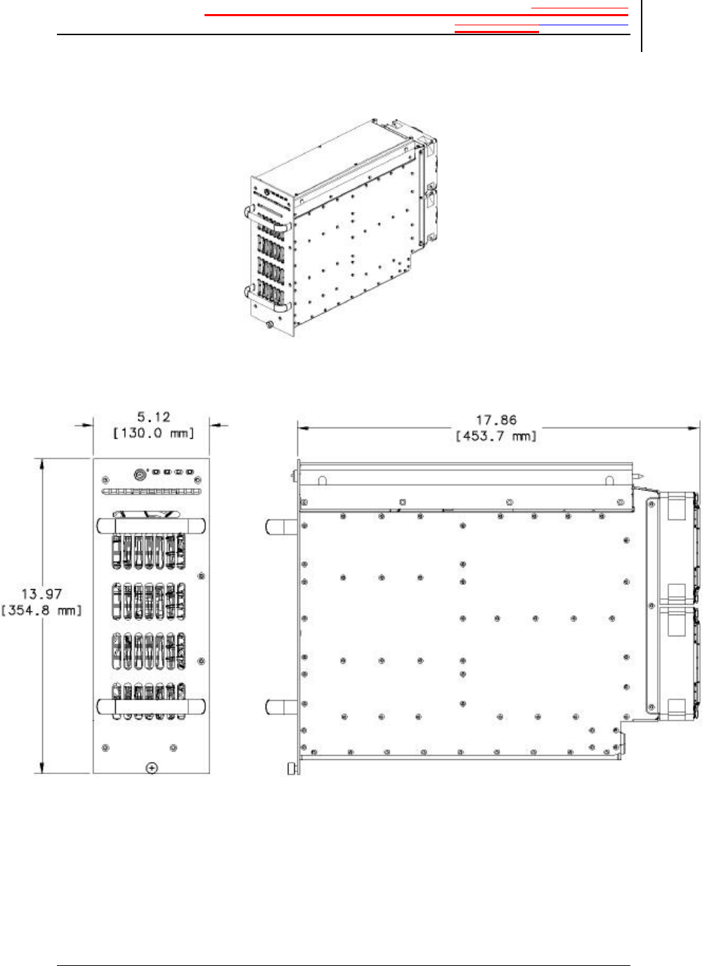
Appendix A3 Major Mechanical SpecificationsPlanning and
PreparationIntroduction
MCPS2135 System Operation 37
2001 Spectrian Corporation. All rights reserved.
MCPA Module for MCPS2135 Family

Appendix A4: MCPS2135 System CheckoutPlanning and
PreparationIntroduction
38 MCPS2135 Operations Manual
2001 Spectrian Corporation. All rights reserved.
Appendix A4: MCPS2135
System Checkout
MCPS System Checkout
In some cases, it may be desirable to perform a system checkout prior to
installation to insure proper operation. The following procedure is included here
only for reference. Accurate specification verification is not guaranteed when
using this procedure.
Equipment Required
• HP4432 Signal Generator
• Sorenson DHP40-250 DC Power Supply
• HP8561A Spectrum Analyzer
• HP436 Power Meter
• HP8481A Power Head
• 750W, 30 dB Attenuator
• Digital Volt Meter (DVM)
Setup Procedure
1. Connect Sorenson DHP-40-250 DC power supply to DC input as outlined
in Section 3.4.
2. Connect HP4432 CDMA Signal Generator to RF input. Set RF level to –
30 dBm. Set I/Q input to internal CDMA generator, IS-97 with EQ, 9
Walsh Codes.
3. Connect Attenuator to RF Output
4. Connect HP8481A Power Sensor to Attenuator output.
5. Connect HP8561A Spectrum Analyzer to Sample Port Output. Set
ATTEN=10 dB, RBW=30kHz, VBW=10kHz, Vid. Avg.=100,
SPAN=10MHz.

Appendix A4: MCPS2135 System CheckoutPlanning and
PreparationIntroduction
MCPS2135 System Operation 39
2001 Spectrian Corporation. All rights reserved.
Performance Checkout Procedure
1. Set current limit on Sorenson power supply to appropriate level as listed
in Table 2.
2. Set DC voltage to 27 ± 1V.
3. With no RF applied, verify that idle current is approximately 13A x
number of MCPA RF modules.
4. Apply RF signal, and slowly increase power to maximum rated power as
listed in Appendix A2.
5. Verify that the total DC current is approximately that listed in Table 2.
6. Perform ACPR measurement. Verify that mask specification exceeds
specification listed in Appendix A2.

INDEXPlanning and PreparationIntroduction
40 MCPS2135 Operations Manual
2001 Spectrian Corporation. All rights reserved.
7 INDEX
acoustic treatment 8
airborne dust 8
air-conditioning 8
alarm configurations 23
alarm connection 9
Alarm Definitions 21
alarm output
connection 18
alarm/protection hierarchy 23
ambient noise 8
AMM 6
installation 16
replacement 28
Amplifier Management Module 6
Amplifier Management Unit 5
Amplifier System Alarms 23
AMPS
modulation 3
AMU 5
Analog Protection Circuit
summary table 23
Analog Protection Circuits 23
average power
rated 32
Block Diagram
RF module 4
building codes 7
bussed power option
DC power 17
cabinet clearance 8
cancellation 4
Caution
definition 2
CDMA 3
CDPD 3
chassis ground 9
checking 16
connection 16
combiner
active 6
combiner losses
output 6
combustible materials
floor covering 7
composite power 11
cooling air 15
critical faults
definition 21
customer service
contact information 31
DC input voltage range 32
DC power supply
requirements 9
DC wire
connecting 17
default alarm
settings 23
degraded operation 22
derate
for altitude 8
DISABLE
RF module 20
dust
removal 28
error loop 4
error signal 4
ESD protective wrapping 13
fan
replacement 29
feed-forward 4
fire codes 7
fire-extinguishing
in site 8
floor covering 7
form C 9
frequency 32

INDEXPlanning and PreparationIntroduction
MCPS2135 System Operation 41
2001 Spectrian Corporation. All rights reserved.
Graphical User Interface 3, 21, 23
ground halo
site 8
grounding system
site 8
guides
module alignment 16
hot air
exhaust 8
hot-swappable
RF modules 28
input drive level
worksheet 10
installation
verify 19
installations
intended 7
Introduction 1
IS-136 TDMA 3
IS-95 3
lighting
working area 7
lightning arrestors 8
lightning protection 8
main loop 4
major faults
definition 21
MCPS address
setting 18
Mechanical Outlines 34
minor faults
definition 21
Module Alarm Hierarchy
table 24
module alarms
summarized 23
Module Alarms 23
Module Replacement 28
multimodule MCPA 25
Note
definition 2
out of service
alarm 22
over-temperature
alarm reset 22
packing lists 12
Periodic Maintenance 28
physical layer
alarms 25
pinout
RS232 33
planning
site 7
positive supply
connecting 17
powering up 19
power-up self-test 20
problem
diagnosis 26
protection circuits
built-in 23
radio parameters 10
recommended power service 9
Replacing MCPS2135 Fan Modules 29
required current 9
return shipment 13
return wire
connecting 17
RF cabling
integrity 17
RF input drive
setting 11
RF load
test 20
RF module
disabling 20
installation 16
RF output
connecting 17
safety equipment
installation 14
self-reset
automatic 22
shipping containers
opening 13
shipping damage 12
shipping documents 12
side support rails 15

INDEXPlanning and PreparationIntroduction
42 MCPS2135 Operations Manual
2001 Spectrian Corporation. All rights reserved.
smoke detectors 8
summarized
alarms 23
uncrating 12
unrestricted airflow 8
vibration 8
Warning
definition 2
weight 7
wrist strap 13, 15