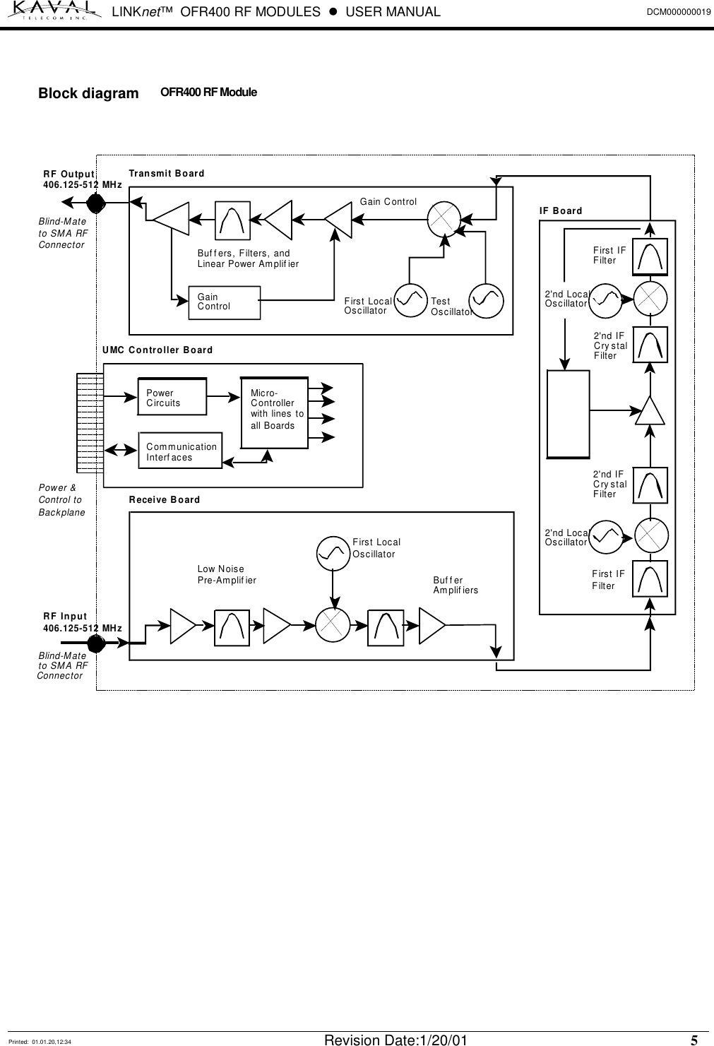
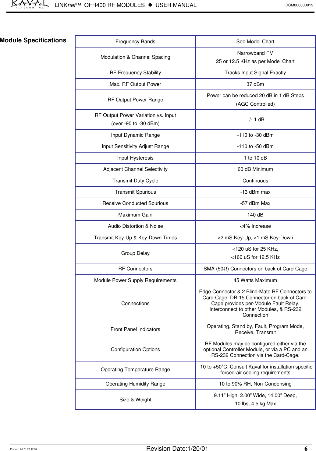
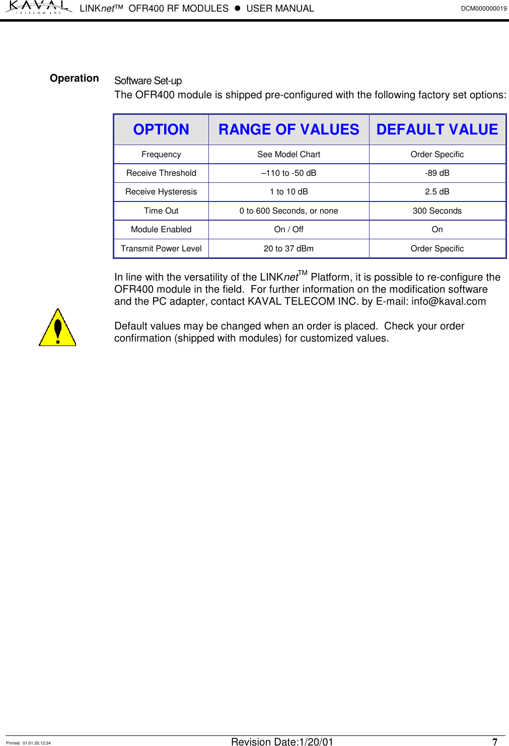
Powerwave Technologies OFR400-A LINKnet OFR400-A RF Module, Model OFR400-A User Manual
Powerwave Technologies Inc. LINKnet OFR400-A RF Module, Model OFR400-A Users Manual
UserManual.wiki
>
Powerwave Technologies
>
OFR400 A User Manual
Users Manual
Navigation menu
Upload a User Manual
Namespaces
Wiki Guide
HTML
PDF
Info
Views
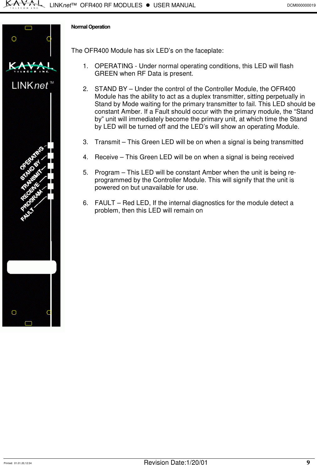
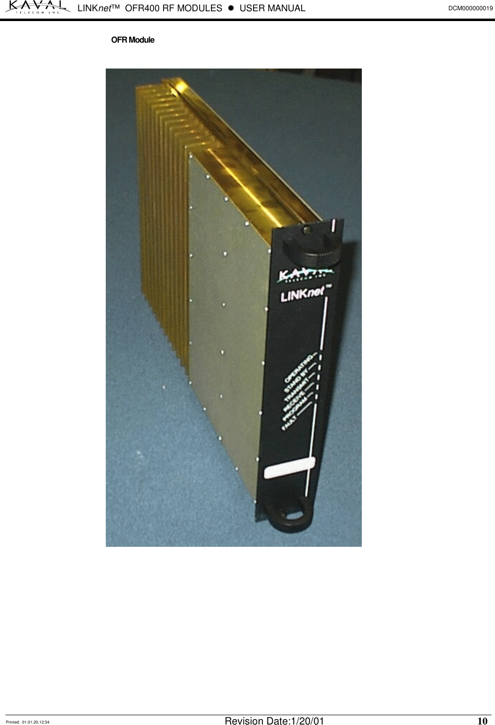
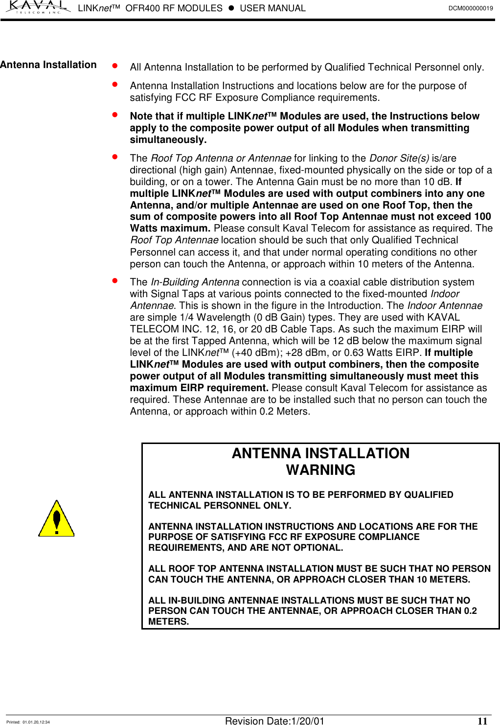
User Manual
Discussion / Help
Navigation