Powerwave Technologies SB800 In-Hancer Plus Bi-Directional Amplifier User Manual Kaval OFR 800
Powerwave Technologies Inc. In-Hancer Plus Bi-Directional Amplifier Kaval OFR 800
users manual
In-Hancer Plus
Bi-Directional Amplifier
User Manual
Installation, Operation
And Maintenance
KAVAL WIRELESS TECHNOLOGIES
60 Gough Road
Markham, Ontario, L3R8X7
Telephone: (888) 86-KAVAL
Web: www.kaval.com
E-mail: info@kaval.com
Document #DCM000000105, Rev.11
October 14, 2003

In-Hancer Plus BDA USER MANUAL DCM000000105
P
PR
RO
OP
PR
RI
IE
ET
TA
AR
RY
Y
S
ST
TA
AT
TE
EM
ME
EN
NT
T
© 2000 KAVAL WIRELESS TECHNOLOGIES All rights reserved.
No part of this publication, or any software included with it may be reproduced, stored in a retrieval system,
or transmitted in any form or by any means, including photocopying, electronic, mechanical, recording or
otherwise, without the prior written permission of the copyright holder.
This document contains proprietary information of KAVAL WIRELESS TECHNOLOGIES The contents are
confidential and any disclosure to persons other than the officers, employees, agents or subcontractors of
the owner or licensee of this document, without the prior written consent of KAVAL WIRELESS
TECHNOLOGIES, is strictly prohibited.
KAVAL WIRELESS TECHNOLOGIES provides this document as is, without any warranty of any kind either
expressed or implied including, but not limited to, the implied warranties of merchantability and fitness of a
particular purpose. KAVAL WIRELESS TECHNOLOGIES may make changes or improvements in the
equipment, software, or specifications described in this document at any time and without notice. These
changes will be incorporated in new releases of this document.
This document may contain technical inaccuracies or typographical errors. KAVAL WIRELESS
TECHNOLOGIES waives responsibility for any labour, materials, or costs incurred by any person or party as
a result of using this document. KAVAL WIRELESS TECHNOLOGIES, and any of its affiliates shall not be
liable for any damages (including, but not limited to, consequential, indirect or incidental, special damages or
loss of profits or date) even if they were foreseeable and KAVAL WIRELESS TECHNOLOGIES has been
informed of their potential occurrence, arising out of or in connection with this document or its use.
T
TR
RA
AD
DE
E
M
MA
AR
RK
K
N
NO
OT
TI
IC
CE
E
This manual makes reference to trademarks that are the property of other companies. References are used
only to refer to the products or services of the trademark owners.
In-Hancer Plus is a trademark of KAVAL WIRELESS TECHNOLOGIES
Printed: 2003-10-14 09:37:26
Revision Date: 10/14/03: ii

In-Hancer Plus BDA USER MANUAL DCM000000105
TABLE OF
CONTENTS
OVERVIEW ............................................................. 4
Introduction....................................................... 4
Line Amplifier BDA's......................................... 4
Off-Air Operation BDA's ................................... 5
Modular Construction ....................................... 6
Theory Of Operation......................................... 6
STANDARD MODELS ............................................... 7
FILTER KITS ........................................................... 8
ACCESSORIES ........................................................ 9
ACCESSORIES FOR STAINLESS-STEEL WEATHER-
RESISTANT ENCLOSURES ..................................... 10
Data Connectors & Cables............................. 10
AC Power Accessories ................................... 11
Accessory Installation..................................... 12
FIBER OPTIC OPTIONS.......................................... 13
INSTALLATION....................................................... 14
In-Hancer Plus BDA Enclosures .................... 14
Un-Packaging ................................................. 14
Mounting the In-Hancer Plus BDA.................. 15
Connections.................................................... 17
RF DECK CONNECTIONS ...................................... 18
BATTERY BACKUP ................................................ 20
IN-HANCER PLUS BDA SPECIFICATIONS................ 21
CARRIER DE-RATING ............................................ 22
INDICATORS ......................................................... 23
CONFIGURATION................................................... 24
ANTENNA INSTALLATION........................................ 25
FCC INFORMATION TO USERS .............................. 26
MAINTENANCE & SAFETY ...................................... 27
STANDARD WARRANTY ......................................... 27
RETURN & REPAIR ............................................... 27
PARTS & ACCESSORIES........................................ 27
Printed: 2003-10-14 09:37:26
Revision Date: 10/14/03: iii
In-Hancer Plus BDA USER MANUAL
Introduction
Overview
The In-Hancer Plus family is a modular Bi-Directional Amplifier product. Bi-
Directional Amplifiers (BDA’s) are radio frequency amplifiers that amplify signals in
two directions. There are two basic BDA Applications; "Line Amplifiers" and “Off-
Air”. Line Amplifiers are low gain (40 dB typical), while Off-Air are high gain (80 dB
typical). The In-Hancer Plus does NOT have separate models for these two
applications, but rather uses non volatile memory and software settings for gain.
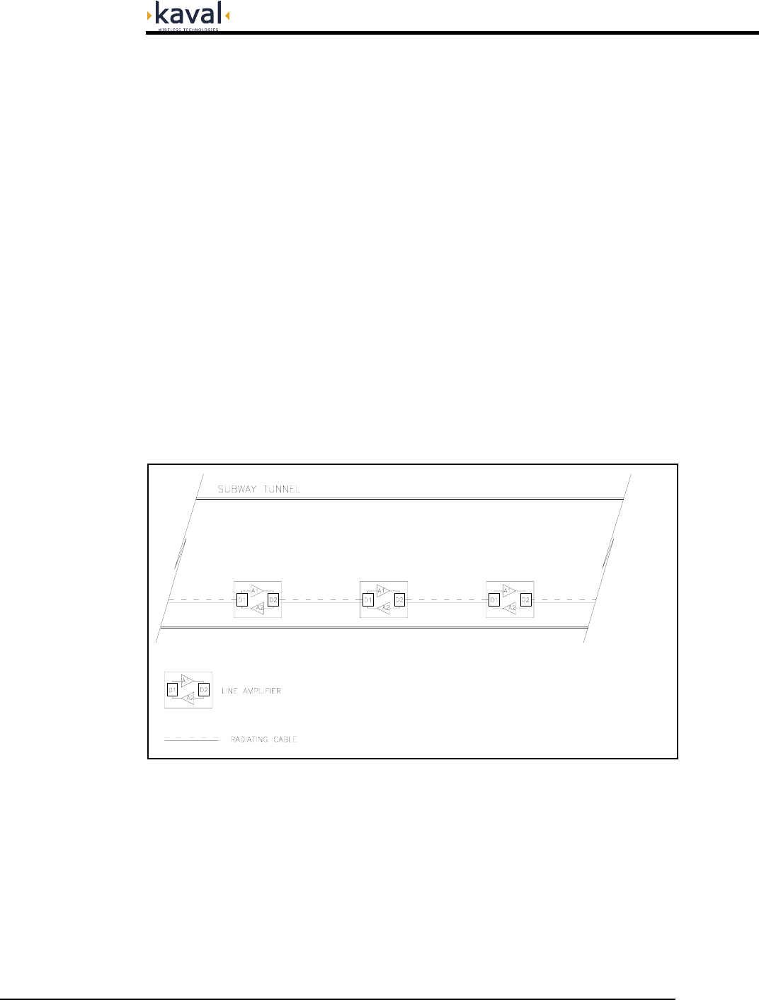
Line Amplifier BDA's
An In-building RF distribution system takes on one of several forms including, but
limited to, radiating cable, distributed tapped radiators, or high power repeater
antennas. For an in-building RF distribution system that requires some gain to
compensate for the system loss, Line Amplifier BDA's are best for the job. Line
Amplifiers provide amplification of RF signals to recover signal loss contributed by
radiating cable and other system components. The Figure below shows an example
of a Tunnel RF Distribution System using Line Amplifiers. The system consists of
Line Amplifiers strategically inserted between radiating cables. As the RF signal
travels along the radiating cable, it loses signal strength. Line Amplifiers compensate
for the RF loss by amplifying the signal back to the desired signal strength before
sending it down the next distribution section, thus maintaining in-building RF
seamless coverage.
Printed: 03.10.14,09:37
Revision Date:10/14/03 4
In-Hancer Plus BDA USER MANUAL
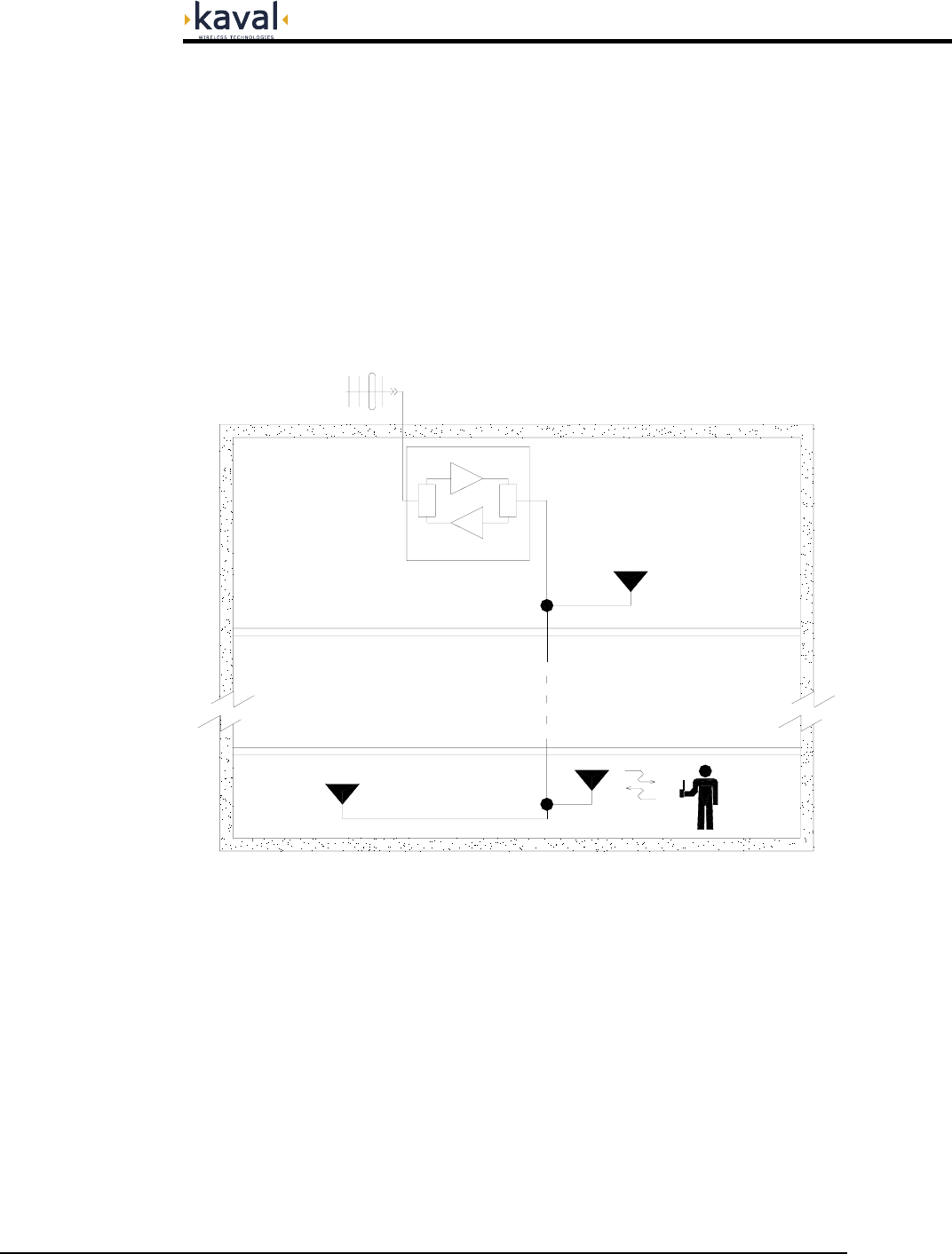
Off-Air Operation BDA's
Off-Air BDA's are intended to extend coverage into areas with coverage deficiency
such as inside office buildings, shopping malls, hospitals, etc. They are designed to
be located independently of the donor site and must be equipped with their own
antenna systems - one to communicate with the donor site and the other(s) to
communicate with portables in the shadow zone. A typical in-building coverage
extension system is shown below. The "Head-End" BDA is responsible for the
amplification of both incoming “Off-Air” downlink signals and outgoing uplink signals.
The in-building distribution antenna system comprises of Coaxial cable, Signal taps,
splitters and antennas to extend coverage on every floor, basement and
underground parking garage.
ROOF TOP ANTENNA
FROM / TO DONOR
TRANSMITTER
D1 D2
A1
A2
SIGNAL
TAP
SIGNAL
TAP
COAXIAL CABLE
N
N - 1
B
F1
F2
KAVAL
800/900 MHz BDA
This distributed antenna system is based on Kaval Wireless Technologies’ “Tapped
Radiator” RF signal distribution approach. The technology makes use of coaxial
cable with Signal Taps strategically located and connected to Omni-directional
ground plane antennas. This technology offers flexibility in system design,
installation and optimization. Once the RF cable backbone has been installed,
additional signal taps and antennas can quickly and easily be added to a live
system, without the need to take the system out of service. Hence, new coverage
areas can be added, or the system can easily be modified if the layout should
change (e.g. modernization retrofits or process modifications).
Printed: 03.10.14,09:37
Revision Date:10/14/03 5
In-Hancer Plus BDA USER MANUAL
Modular Construction
The basic In-Hancer Plus BDA building blocks are.
• RF-Deck: an Amplifier and Controller assembly mounted on a heat-sink
ready to install in an enclosure or rack. These include RF output Isolators.
• Enclosure including Power Supply.
• Optional Batteries for backup.
• Filter Kit including Duplexers, Filters and mounting hardware, if not already
included in base Model.
This manual lists complete Standard Models, some of which are complete products
as is, and others require the selection of a Filter Kit. There is also a series of add-
on Accessories and Options.
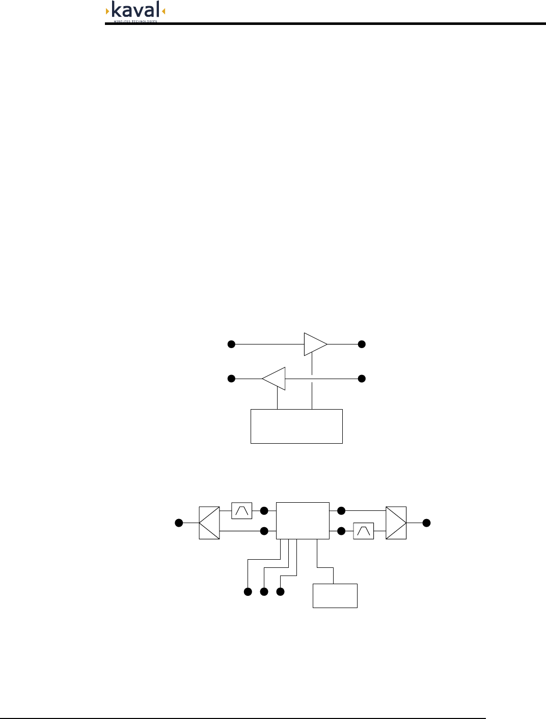
Theory Of Operation
The In-Hancer Plus BDA uses the RF-Deck as the fundamental active element. RF-
Decks include both Uplink and Downlink RF Amplifiers, Microprocessor based
Controller, and Power Supply / Battery Charging...
CONTROLLER
DOWNLINK AMPLIFIER
UPLINK AMPLIFIER
UPLINK RF OUT
DOWNLINK RF IN DOWNLINK RF OUT
UPLINK RF IN
These are assembled into an enclosure with a Filter Kit...
RF-DECK
DL OUTDL IN
UL OUT UL IN
FILTER
FILTER
DUPLEXER DUPLEXER
UPLINK /
DONOR
RF PORT
DOWNLINK /
RF PORT
DISTRIBUTION
POWER
SUPPLY
I/O PORTS
Printed: 03.10.14,09:37
Revision Date:10/14/03 6

In-Hancer Plus BDA USER MANUAL DCM000000105
MODEL DESCRIPTION ENCLOSURE
UHF MODELS
Note that UHF Models DO NOT include Filtering and Duplexing.
See the standard Filter Kits on the next page.
SB400-A 403-430 MHz
(to 380 MHz for special applications)
Large Painted Enclosure
SB400-A-SS 403-430 MHz
(to 380 MHz for special applications)
Large Stainless-Steel Enclosure
SB400-B 450-512 MHz Large Painted Enclosure
SB400-B-SS 450-512 MHz Large Stainless-Steel Enclosure
800-900 MHz Models
With exceptions as noted, 800-900 MHz Models DO include Filtering & Duplexing.
For the exceptions, see the standard Filter Kits on the next page.
SB800-T 806-821 / 851-866 MHz (Trunking) Small Painted Enclosure
SB800-T-SS 806-821 / 851-866 MHz (Trunking) Small Stainless-Steel Enclosure
SB800-TP 806-824 / 851-869 MHz (Trunking/P-S) Small Painted Enclosure
SB800-TP-SS 806-824 / 851-869 MHz (Trunking/P-S) Small Stainless-Steel Enclosure
SB800-PS 821-824 / 866-869 MHz (Public Safety) Large Painted Enclosure
SB800-PS-SS 821-824 / 866-869 MHz (Public Safety) Large Stainless-Steel Enclosure
SB800-C 824-849 / 869-894 MHz (Full Cellular) Small Painted Enclosure
SB800-C-SS 824-849 / 869-894 MHz (Full Cellular) Small Stainless-Steel Enclosure
SB800-CB 835-849 / 880-894 MHz (Cell B Band) Small Painted Enclosure
SB800-CB-SS 835-849 / 880-894 MHz (Cell B Band) Small Stainless-Steel Enclosure
SB900-P 896-902 / 935-941 MHz (Paging) Small Painted Enclosure
SB900-P-SS 896-902 / 935-941 MHz (Paging) Small Stainless-Steel Enclosure
SB900-PE 896-902 / 928-941 MHz (Ext Paging) Small Painted Enclosure
SB900-PE-SS 896-902 / 928-941 MHz (Ext Paging) Small Stainless-Steel Enclosure
SB900-P3 896-902 / 928-941 MHz
(with a tuneable 1-3 MHz Downlink Filter)
Small Painted Enclosure
SB900-P3-SS 896-902 / 928-941 MHz
(with a tuneable 1-3 MHz Downlink Filter)
Small Stainless-Steel Enclosure
SB800-TPX-1 806-824 / 851-869 MHz (No Filters) Small Painted Enclosure
SB800-TPX-1SS 806-824 / 851-869 MHz (No Filters) Small Stainless-Steel Enclosure
SB800-TPX-2 806-824 / 851-869 MHz (No Filters) Large Painted Enclosure
SB800-TPX-2SS 806-824 / 851-869 MHz (No Filters) Large Stainless-Steel Enclosure
SB800-CX-1 824-849 / 869-894 MHz (No Filters) Small Painted Enclosure
SB800-CX-1SS 824-849 / 869-894 MHz (No Filters) Small Stainless-Steel Enclosure
SB800-CX-2 824-849 / 869-894 MHz (No Filters) Large Painted Enclosure
SB800-CX-2SS 824-849 / 869-894 MHz (No Filters) Large Stainless-Steel Enclosure
SB900-PX-1 896-902 / 928-941 MHz (No Filters) Small Painted Enclosure
SB900-PX-1SS 896-902 / 928-941 MHz (No Filters) Small Stainless-Steel Enclosure
SB900-PX-2 896-902 / 928-941 MHz (No Filters) Large Painted Enclosure
SB900-PX-2SS 896-902 / 928-941 MHz (No Filters) Large Stainless-Steel Enclosure
Standard Models
Printed: 03.10.14,09:37
Revision Date:10/14/03 7
In-Hancer Plus BDA USER MANUAL DCM000000105
KIT MODEL DESCRIPTION
UHF Filter Kits
SB400-F1 UHF Filter Kit for any gain, 380-512MHz,
1MHz Bandwidth, 5MHz Tx/Rx Separation. (Large Encl only)
SB400-F2L UHF Filter Kit for up to 40dB gain, 406-512MHz,
1.5MHz Bandwidth, 3MHz Tx/Rx Separation. (Large Encl only)
SB400-F2H1 UHF Filter Kit for up to 80dB gain, 406-430MHz,
1.5MHz Bandwidth, 3MHz Tx/Rx Separation. (Large Encl only)
SB400-F2H2 UHF Filter Kit for up to 80dB gain, 450-470MHz,
1.5MHz Bandwidth, 3MHz Tx/Rx Separation. (Large Encl only)
SB400-F2H3 UHF Filter Kit for up to 80dB gain, 470-512MHz,
1.5MHz Bandwidth, 3MHz Tx/Rx Separation. (Large Encl only)
SB400-F3 UHF Filter Kit for any gain, 406-512MHz,
1.5MHz Bandwidth, 5MHz Tx/Rx Separation. (Large Encl only)
SB400-F4L UHF Filter Kit for up to 40dB gain, 406-512MHz,
3MHz Bandwidth, 5MHz Tx/Rx Separation. (Large Encl only)
SB400-F4H1 UHF Filter Kit for up to 80dB gain, 406-430MHz,
3MHz Bandwidth, 5MHz Tx/Rx Separation. (Large Encl only)
SB400-F4H2 UHF Filter Kit for up to 80dB gain, 450-470MHz,
3MHz Bandwidth, 5MHz Tx/Rx Separation. (Large Encl only)
SB400-F4H3 UHF Filter Kit for up to 80dB gain, 470-512MHz,
3MHz Bandwidth, 5MHz Tx/Rx Separation. (Large Encl only)
SB400-F5 UHF Filter Kit for any gain, 380-512MHz,
5MHz Bandwidth, 10MHz Tx/Rx Separation. (Large Encl only)
800-900 MHz Filter Kits
SB800-F-SMR 800MHz Filter Kit for 806-821 / 851-866MHz.
SB800-F-SMR-PS 800MHz Filter Kit for 806-824 / 851-869MHz.
SB800-F-PS 800MHz Filter Kit for 821-824 / 866-869MHz. (Large Encl only)
SB800-F-CELL 800MHz Filter Kit for 824-849 / 869-894MHz.
SB800-F-CELLB 800MHz Filter Kit for 835-849 / 880-894MHz.
SB900-F-PAG1 800MHz Filter Kit for 896-902 / 935-941MHz.
SB900-F-PAG2 800MHz Filter Kit for 896-902 / 928-941MHz.
SB900-F-PAG3 3MHz Add-on Filter for 851-960MHz.
Filter Kits
For custom Filter Kits, please consult Kaval's Engineering Services.
Printed: 03.10.14,09:37
Revision Date:10/14/03 8
In-Hancer Plus BDA USER MANUAL DCM000000105
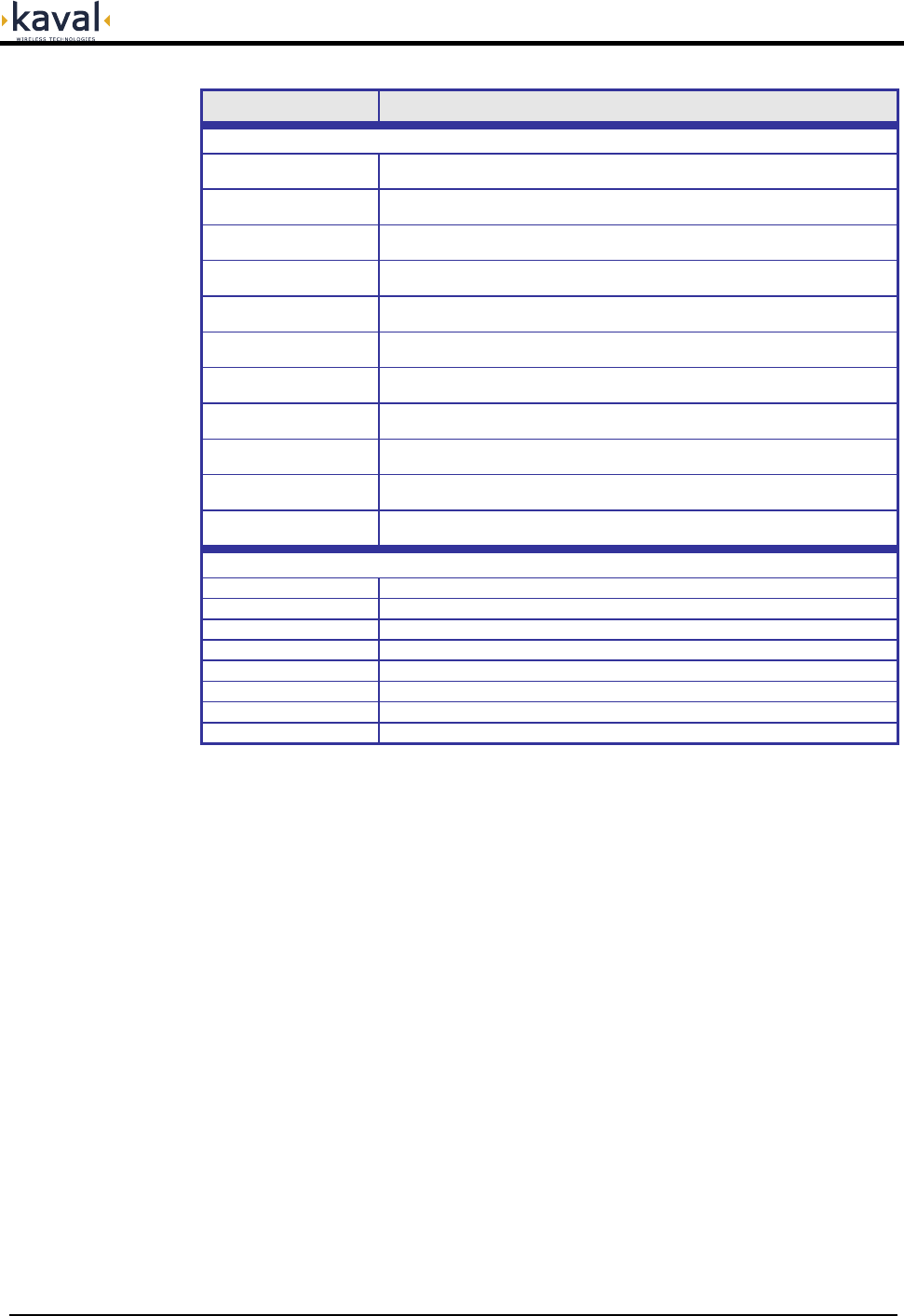
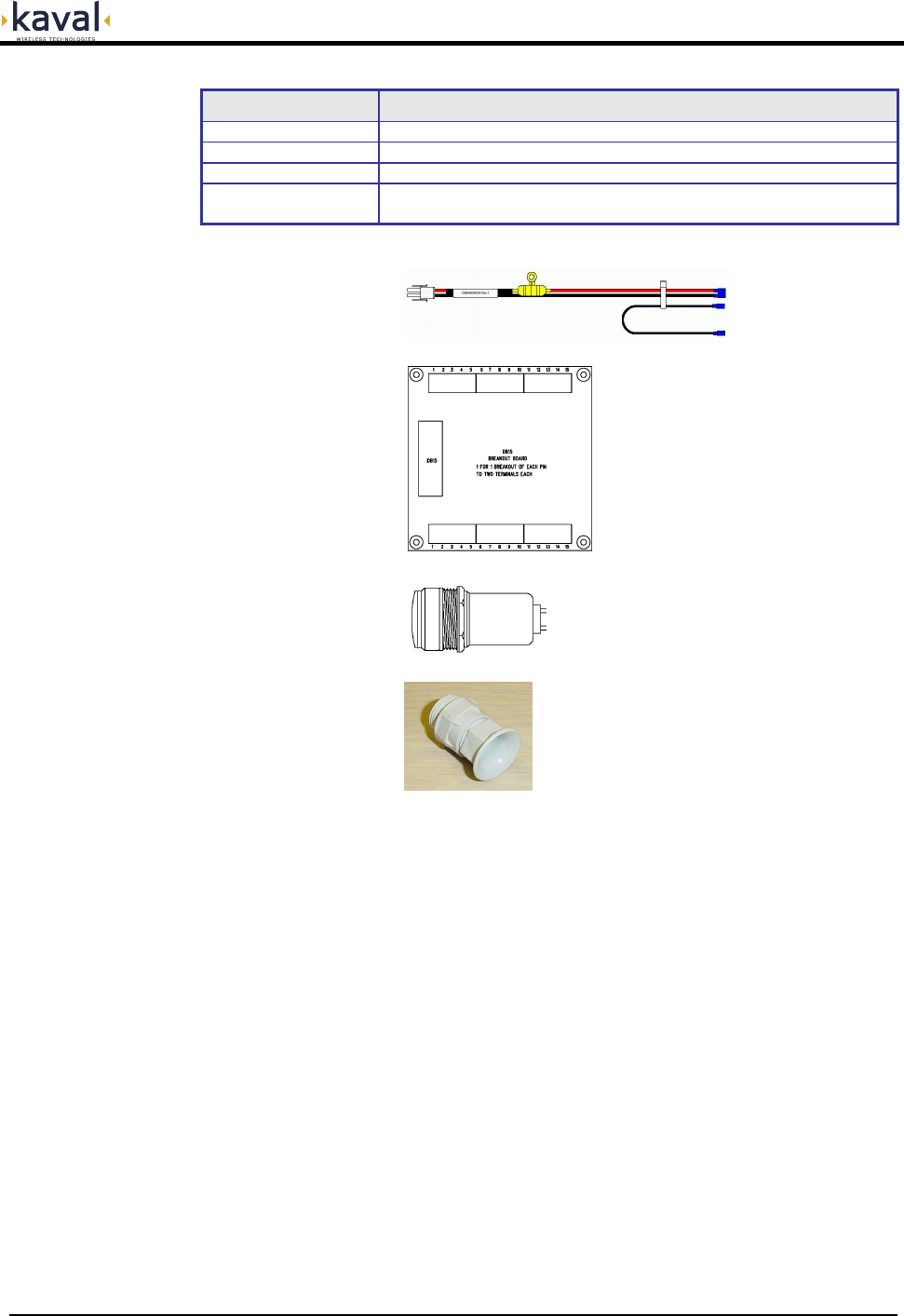
MODEL DESCRIPTION
SB-BATT-CAB Battery Cable
SB-DB15 DB15 Breakout Kit (SB-ENCL-01 & -02 only)
SB-LITE External Status Indicator Lamp to be mounted on front of Enclosure
SB-GLAND Cable Gland for Wires or Fiber.
There are openings on the bottom of the Enclosures for these.
Accessories
SB-BATT-CAB
SB-DB15
SB-LITE
SB-GLAND
Printed: 03.10.14,09:37
Revision Date:10/14/03 9
In-Hancer Plus BDA USER MANUAL DCM000000105
Accessories for
Stainless-Steel
Weather-Resistant
Enclosures
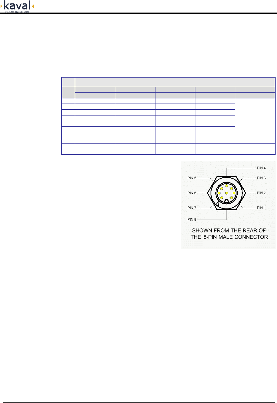
Data Connectors & Cables
For the Stainless-Steel Weather-Resistant Enclosures, if RS232 or User I/O
connections are needed outside of the enclosure, then weather-resistant
connections are required. These are available through cables that mount inside the
enclosure, connect to the RF Deck's Control Board, and then to gasketed 8-pin
connectors that mount on the enclosure bottom.
MODEL & DESCRIPTION
SB-DATA-00 SB-DATA-01 SB-DATA-02 SB-DATA-03 SB-DATA-03A
Pin Ext Pigtail Relay & I/O CAN & I/O RS232 Ext RS232
1 Black Wire Relay NO CAN-H DCD In
2 White Wire Relay Common CAN-L Tx Out
3 Red Wire Relay NC CAN Common Rx In
4 Green Wire Aux.In #2 Aux.In #2 RI In
5 Brown Wire Aux.Out #2 Aux.Out #2 Ground
6 Blue Wire Aux.Out #3 Aux.Out #3 +5 VDC Power
7 Orange Wire Ground Ground CTS In
8 Yellow Wire +28 VDC Power +28 VDC Power RTS Out
Brings RF Deck
RS232 Ports
back out to a
mating DB9
Connector
Used Outside
Enclosure
Used Inside
Enclosure
Used Inside
Enclosure
Used Inside
Enclosure
Used Outside
Enclosure
Note that the CAN Network connection is
optically-isolated, so the CAN Common line
is NOT the same as ground.
The circular 8-pin connectors have a sealed
cap/cover to protect the connector when not
in use.
Custom cables may be defined.
Printed: 03.10.14,09:37
Revision Date:10/14/03 10
In-Hancer Plus BDA USER MANUAL DCM000000105
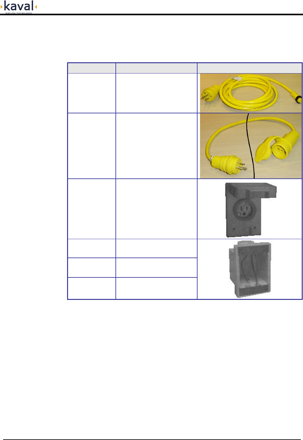
AC Power Accessories
The AC Power is brought into the Stainless-Steel Enclosure via a water-tight cable
that is included with the In-Hancer Plus BDA. Optional Accessories include...
MODEL DESCRIPTION PHOTO
SB-AC-CORD1
Replacement
Water-Tight
AC Line Cord
8'
SB-EXT-CORD
Water-Tight
Extension Cord
25'
SB-OUTLET1
Water-Tight
AC Outlet
with Cover
SB-AC-BOX1 AC Box for Outlet
with 1/2" Knockout
SB-AC-BOX2 AC Box for Outlet
with 3/4" Knockout
SB-AC-BOX3 AC Box for Outlet
with 1" Knockout
Printed: 03.10.14,09:37
Revision Date:10/14/03 11
In-Hancer Plus BDA USER MANUAL DCM000000105
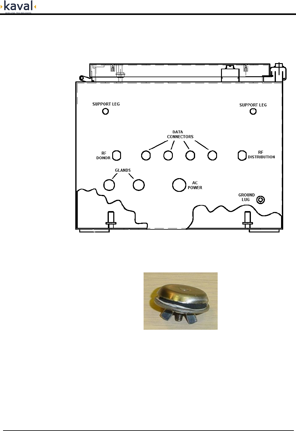
Accessory Installation
For the Stainless-Steel Weather-Resistant Enclosures, most external accessories
install on the bottom, except for the SB-LITE which mounts on the door.
There are openings on the bottoms of the Enclosures for 4 Data Connectors and two
of optional SB-GLAND. When not used these openings are sealed with weather-
resistant plugs...
Replacements for these may be ordered as Kaval Part SB-PLUG.
Printed: 03.10.14,09:37
Revision Date:10/14/03 12
In-Hancer Plus BDA USER MANUAL DCM000000105
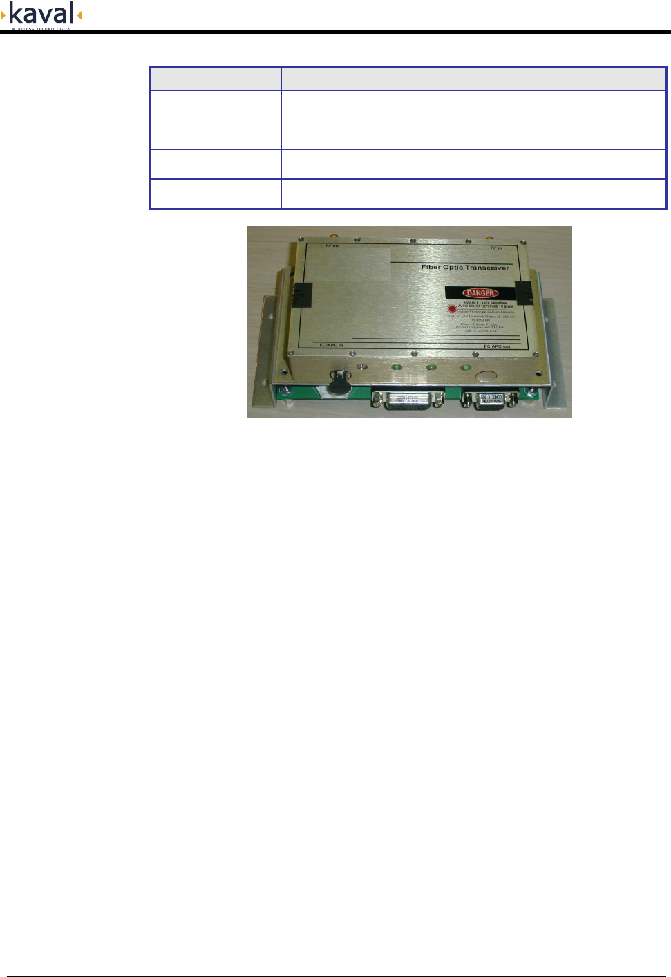
MODEL DESCRIPTION
SB-FIB13
Fiber-Optic I/F
RF over Fiber Interface Module, Dual-Fiber
1310 nM Laser
SB-FIB13W
Fiber-Optic I/F
RF over Fiber Interface Module, Single-Fiber (WDM)
1310 nM Laser
SB-FIB15
Fiber-Optic I/F
RF over Fiber Interface Module, Dual-Fiber
1550 nM Laser
SB-FIB15W
Fiber-Optic I/F
RF over Fiber Interface Module, Single-Fiber (WDM)
1550 nM Laser
Fiber Optic Options
These are Factory Installed Options. Consult Kaval's Engineering Services for more
information.
Printed: 03.10.14,09:37
Revision Date:10/14/03 13
In-Hancer Plus BDA USER MANUAL DCM000000105
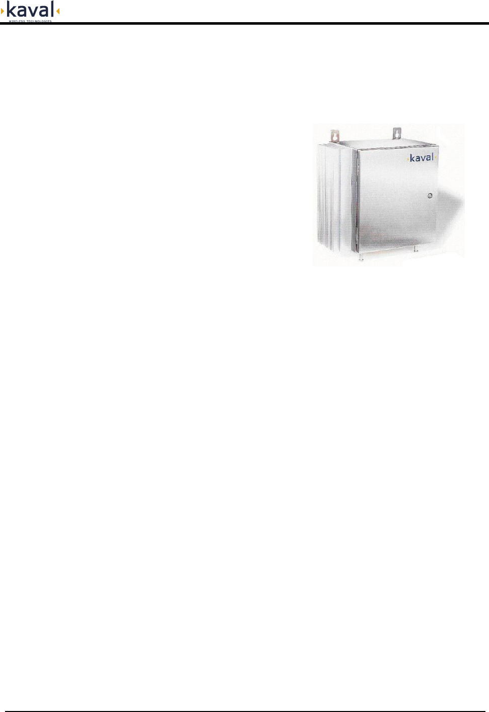
Installation In-Hancer Plus BDA Enclosures
There are four standard BDA Enclosures, 2 sizes (Large and Small) of Painted
Enclosures suitable for use in Electrical Rooms, and 2 sizes (Large and Small) of
Stainless-Steel Enclosures which are sealed for enhanced Weather / Water
Resistance.
Painted Enclosure Photo is TBD
Un-Packaging
Each In-Hancer Plus BDA is carefully packaged for air shipment. Any damage
incurred during the transportation must be claimed from the shipper. Make sure the
following necessary equipment and hardware are available and undamaged.
In-Hancer Plus BDA (supplied by Kaval Wireless Technologies)
Two 50-Ohm jumper cables (not supplied by Kaval Wireless Technologies)
AC power cord.
AC Outlet is nearby (not supplied by Kaval Wireless Technologies)
Mounting hardware such as: Four washers and four bolts (not supplied by Kaval
Wireless Technologies)
Make sure the mounting area is large enough to accommodate the installation of
the enclosure and free airflow is available on both sides of the cabinet.
Printed: 03.10.14,09:37
Revision Date:10/14/03 14
In-Hancer Plus BDA USER MANUAL DCM000000105
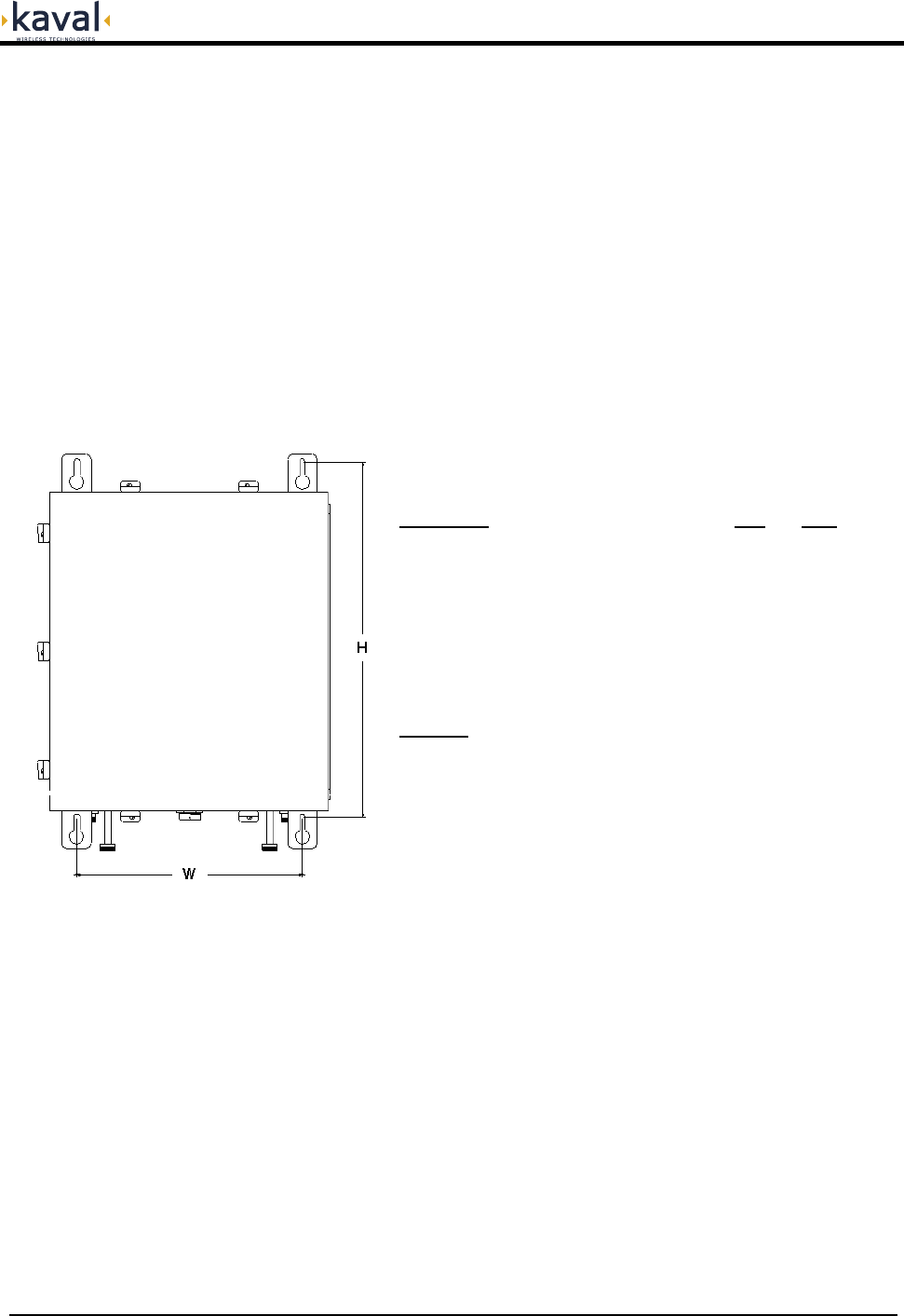
Mounting the In-Hancer Plus BDA
The physical installation is accomplished by mounting the enclosure onto a vertical
wall. Ensure that the unit is mounted in the upright position, as indicated by the
upright Kaval Wireless Technologies’ logo. Using four mounting lugs on the
enclosure as a template insert four bolts to the wall. Make sure the bolts are capable
of supporting the weight. The enclosure can be mounted as described below:
Raise the enclosure so that it about 1” to 3” away from the bolts so that one
can see the bolts through the larger diameter of the keyhole slots.
Move the enclosure closer to the wall so that those four keyhole type slots are
hooked onto the bolts.
Slide the enclosure down until all bolts fit well in the narrow part of the keyhole
slots.
Enclosure "H" "W"
Small Painted Enclosure TBD TBD
Small Stainless Steel Enclosure 18.0" 11.5"
Large Painted Enclosure TBD TBD
Large Stainless Steel Enclosure 26.0" 18.0"
NOTE: The Stainless Steel Enclosures are
sealed for enhanced Weather / Water
Resistance.
Printed: 03.10.14,09:37
Revision Date:10/14/03 15
In-Hancer Plus BDA USER MANUAL DCM000000105
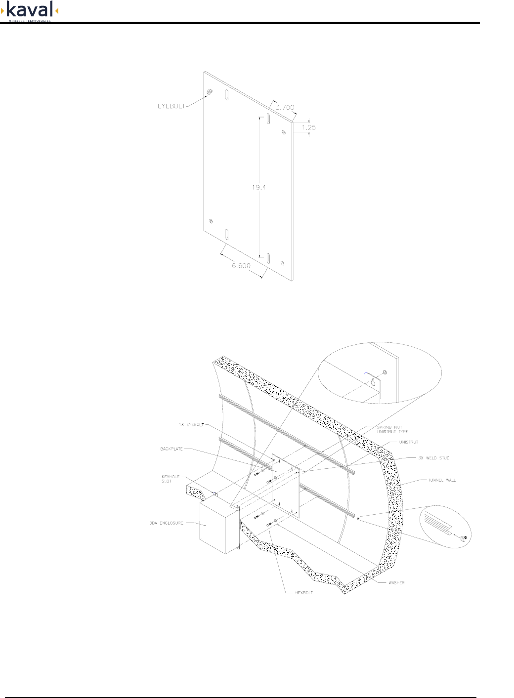
The Small Stainless Steel Enclosure may also be mounted onto an optional Mounting Plate
for quick installation and replacement...
This is especially important in Subway Tunnel applications...
Printed: 03.10.14,09:37
Revision Date:10/14/03 16
In-Hancer Plus BDA USER MANUAL DCM000000105
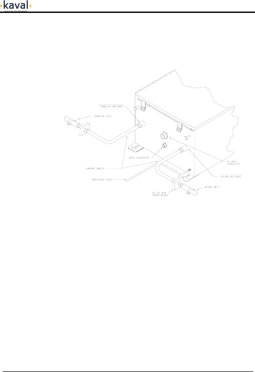
Connections
In-Hancer Plus BDA Connectors are on the bottom of the enclosure. RF cables can
be connected to these connectors using RF cables as follows.
Connect the in-building Distributed Antenna System cable to the Uplink port.
Connect the Donor Site cable to the Downlink port.
Connect AC Power.
Connect any Data Cables.
AC Power and RF Connections should be installed with all standard installation
practices for lightning protection. This includes the grounding and electrical bonding
together of all equipment racks and cabinets in the room. It also includes a
grounding of the primary antenna cable and the installation of proper surge
suppression (lightning arrestor) equipment at the entrance to the equipment room. It
is highly recommended that AC Power Wiring be performed by a qualified Electrician
so as to ensure compliance with all National and Local Electrical Wiring Regulations.
Connecting power cables can be done as follows:
The In-Hancer Plus BDA enclosure can be grounded by connecting a No. 6
copper grounding wire to the grounding stud located at the bottom of the
enclosure.
Connect the power cable to the AC INPUT connector located at the bottom of
the enclosure.
Set the In-Hancer Plus BDA operating parameters using a PC or via the CAN
Network.
Printed: 03.10.14,09:37
Revision Date:10/14/03 17
In-Hancer Plus BDA USER MANUAL DCM000000105
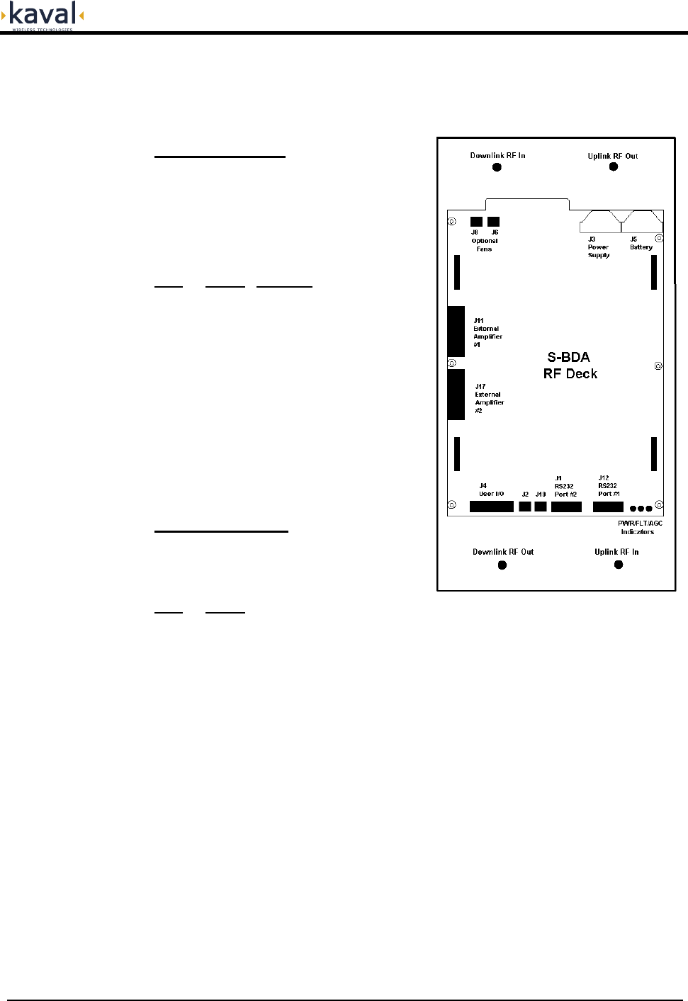
As previously described, the core of an In-Hancer Plus BDA is the RF Deck. The
diagram below shows the RF Deck, its
Indicators and Connectors...
RF Deck Connections
RS232 Connectors:
RS232 Port #1 is for connecting directly
to a PC via a straight-through male to
female DB9 cable. The PC interface is
described later.
RS232 Port #2 is for special software
defined interfacing.
Pin# Signal Direction
1 * DCD Input
2 Tx Output
3 Rx Input
5 Ground
6 +5V Output
7 CTS Input
8 RTS Output
9 * RI Input
* RS232 Port #2 Only !
The +5V is current limited to about 0.5
ampere maximum.
User I/O Connector:
This provides a variety of I/O
functionality via a 15-pin Female D-Sub
Connector...
Pin# Signal
1 CAN High (isolated)
9 CAN Low (isolated)
8 CAN Com. (isolated)
3 Fault Relay Common
2 Fault Relay - Closed for Fault
5 Fault Relay - Open for Fault
6 +28V Power
7 Ground
10 Auxiliary Input #1
11 Auxiliary Input #2
12 Auxiliary Input #3
13 Auxiliary Output #1
14 Auxiliary Output #2
15 Auxiliary Output #3
Note that the CAN Network connection is optically-isolated, so the CAN Common
line is NOT the same as ground. Auxiliary Output #1 is also available at connector
J2, and Auxiliary Input #1 is also available at connector J19.
Printed: 03.10.14,09:37
Revision Date:10/14/03 18
In-Hancer Plus BDA USER MANUAL DCM000000105
The +28V Power is current limited to about 0.5 ampere maximum.
The Form-C Fault Relay is rated at 30 VDC 30 VAC @ 0.5 Amp.
For the CAN Network wiring, refer to the DCM000000103 CAN Wiring Guide.
The three Auxiliary Inputs are intended for connection to external contact-closures
connected between the input and ground. Each one, if closed, will create a Fault
Condition Auxiliary Input #1 is also available at connector J19.
The three Auxiliary Outputs are intended for connection to external devices such
as relay coils or lamps. The external devices are connected between the output and
+28V. They are rated at 100mA each. Auxiliary Output #1 is intended for use with
the SB-LITE optional External Status Indicator Lamp, and is available for that application
via connector J2. The function of Auxiliary Output #1 - the Status Light, is...
Normal Operating Conditions - Lighted Steadily.
Fault Conditions - Flashing
Loss of all Power - Off
The other two Auxiliary Outputs are to be custom software configured.
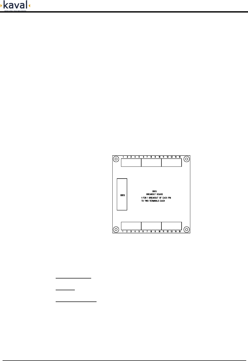
Note that the SB-DB15 DB15 Breakout Kit may be ordered to bring the User I/O
connections out to screw terminals for easy wiring...
This 4" x 4" Board mounts onto four 3.5" x 3.5" #6 locations, and includes a 6' DB15
to DB15 Cable.
For the Weather-Resistant Enclosures use the Data Cables.
Power Supply: Connected to the internal 28VDC Power Supply.
Battery: Connected to an optional Backup Battery.
RF Connections: As described, these would be configured internally by Kaval.
Printed: 03.10.14,09:37
Revision Date:10/14/03 19

In-Hancer Plus BDA USER MANUAL DCM000000105
If the In-Hancer Plus BDA is being used without a Battery it must be configured to
NOT use a battery. Without a battery the BDA will shut down or reset with any
disruption to the AC power. When power is re-established the system will restart
automatically within 30 seconds. External batteries may be connected using the SB-
BATT-CAB Battery Cable. The BDA has a built-in battery charger that will
automatically recharge the attached battery.
Battery Backup
Refer to DCM000000102 "Battery Backup Manual".
For Battery Backup purposes...
Vbat = 24 VDC Ic = 0.5 Ampere Id = 2.5 Ampere
Printed: 03.10.14,09:37
Revision Date:10/14/03 20

In-Hancer Plus BDA USER MANUAL DCM000000105
Frequency Bands See Model Charts
Passband Ripple
(Typical)
± 2.5 dB
(Depends upon Filtering choices)
Gain Range
(Typical)
30 to 80dB Typical for 800-900 MHz Models
28 to 78dB for UHF Models
(the gains have some variation
for certain filtering combinations)
Digital Gain Adjustment In 1 dB Increments
AGC
(Power Levelling)
When active will limit composite output
power to a level between +15 to +30dBm.
Has fast attack and slow decay so as to
NOT interfere with complex signals such as
CDMA, GSM, iDEN, etc.
AGC Dynamic Range 40dB for 800-900 MHz Models
25dB for UHF Models
RF Power
3'rd Order Intercept Point IP3
+45 dBm Typical for 800-900 MHz Models
+44dBm Typical for UHF Models
(see de-rating chart)
Noise Figure < 8 dB for 800-900 MHz Models
<12dB for UHF Models
Propagation Delay <5 µs
(dependent upon filtering choices)
Impedance 50 ohms
VSWR <2:1
Maximum RF Input +10 dBm without damage
Primary Power 120/240VAC, 50-60Hz,
100VA Typical, 150VA Max.
Optional Secondary Power /
Battery Backup
Two 12 VDC Sealed Lead -Acid
Batteries, 10-100 AH.
See DCM000000102.
Dimensions W x H x D
(incl. Heatsink,
but NOT Mounting Tabs)
Approx. 17"x16.5"x11" for Small Enclosures
Approx. 27"x24"x11" for Large Enclosures
Weight 60 lbs. approx. for Smaller Enclosure
120 lbs. approx. for Larger Enclosure
Housing
Rugged - Wall Mountable
Stainless Steel options for
weather resistant.
Connectors N female
Operating Temperature Range -10°C to +50°C
Humidity 5% to 95% RH Max, Non-Condensing
FCC Identifier FCC: H6M-SB400 UHF
H6M-SB800 800-900 MHz
Industry Canada Certification IC: 1541A-SB400 UHF
1541A-SB800 800-900 MHz
In-Hancer Plus BDA
Specifications
NOTE: The Stainless Steel Enclosures are sealed for enhanced
Weather / Water Resistance.
Printed: 03.10.14,09:37
Revision Date:10/14/03 21
In-Hancer Plus BDA USER MANUAL DCM000000105
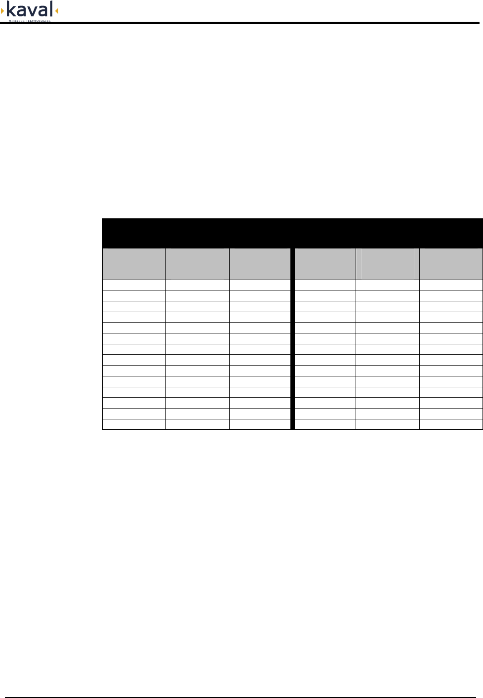
There are two requirements for the de-rating of RF Carriers in a multiple channel
environment; one is Intermodulation - signals produced from non-linear effects
between the intended channel signals. This intermodulation may cause interference
to receiving equipment. In order to minimize Intermodulation signals, Power de-
rating must be applied. In the USA there are FCC Intermodulation Specifications
published in the EIA Standard PN2009.
Carrier De-Rating
The second requirement is de-rating to maintain the integrity of complex digital
communications signals.
The Tables below gives the maximum per channel Output Levels allowed as a
function of the number of channels. Note that depending on the actual input levels,
the gain may need to be reduced.
The figures shown are to the nearest dB, and are for the 800-900MHz In-
Hancer Plus BDA's. For UHF Models a further de-rating of 2dB is required.
FM Carriers (output levels)
(for 800-900MHz; de-rate by -1 to -2 dB for UHF)
Complex Carriers (output levels)
(CDMA, GSM, iDEN, etc)
(for 800-900MHz; de-rate by -1 to -2dB for UHF)
Number of
Carriers
Power per
Carrier
(dBm)
Total Power
(dBm)
Number of
Carriers
Power per
Carrier
(dBm)
Total Power
(dBm)
1 +37 +37 1 +27 +27
2 +26 +29 2 +21 +24
3 +23 +28 3 +18 +23
4 +21 +27 4 +16 +22
5 +19 +26 5 +14 +21
6 +18 +26 6 +13 +21
7 +17 +25 7 +12 +20
8 +16 +25 8 +11 +20
9 +15 +25 9 +10 +20
10 +14 +24 10 +9 +19
15 +12 +24 15 +7 +19
20 +10 +23 20 +5 +18
25 +9 +23 25 +4 +18
30 +8 +22 30 +3 +17
Maintaining the above composite output power levels may be accomplished by
setting both Gain and AGC Levels appropriately.
Consult Kaval Wireless Technologies for further information.
Printed: 03.10.14,09:37
Revision Date:10/14/03 22

In-Hancer Plus BDA USER MANUAL DCM000000105
The three LED Indicators on the RF Deck are...
Indicators
POWER: This LED will be GREEN when the BDA is operating.
FAULT: This LED will light AMBER for any Fault Condition.
AGC: This LED will light AMBER when the Power Limiting is on.
The optional SB-LITE External Lamp indicates...
Normal Operating Conditions: Lighted Steadily.
Fault Conditions: Flashing
Loss of all Power: Off
The In-Hancer Plus BDA continuously performs internal diagnostics. If a fault is
detected it will activate its Fault LED and Fault Relay. Faults detected include...
•
•
•
Over Temperature
Over / Under Current
Misc. Internal Faults
Detailed Faults are detected by the optional Gateway Module. Details may also be
determined via an RS232 connected Terminal Emulator using the LIST command.
Printed: 03.10.14,09:37
Revision Date:10/14/03 23

In-Hancer Plus BDA USER MANUAL DCM000000105
It is possible to re-configure an In-Hancer Plus BDA in the field, either with a
Personal Computer (PC) or via the optional LinkNet Gateway Module. To use a
PC it is necessary to use a straight-through DB9 male to female cable to connect the
RS232 Port #1 DB9 connector on the RF Deck to a standard DB9 RS232 Connector
on the PC. On the PC a terminal emulation program such as HyperTerminal is used
to communicate to the In-Hancer Plus BDA. The settings are 9600 baud, 8 bits, no
parity, and 1 stop bit. Commands are one or two words followed by pressing Return.
Commands may be given in upper or lower-case. Available commands are...
Configuration
ACCESS USER Required as a simple password to gain access to customer
settable parameters and diagnostics; This will time-out after 10
minutes, and may have to be re-typed.
HELP or ? Displays a list of Available Commands.
LIST Displays Current Settings and Status Faults, Etc.
VER Display the current Version of Software.
ENABLE 1 or 0 Enables or Disables the Module.
DLEN 1 or 0 Enables or Disables the Downlink Amplifier.
ULEN 1 or 0 Enables or Disables the Uplink Amplifier.
DLGAIN ### Displays or Sets the Downlink Gain (in tenths of a dB).
ULGAIN ### Displays or Sets the Uplink Gain (in tenths of a dB).
DLAGC ### Displays or Sets the Downlink AGC Level (in tenths of a dBm).
ULAGC ### Displays or Sets the Uplink AGC Level (in tenths of a dBm).
DLAGCEN 1 or 0 Enables or Disables Downlink AGC.
ULAGCEN 1 or 0 Enables or Disables Uplink AGC.
NETID ### Sets the Network ID.
BACKUP 0, 1, or 2 Sets the Power Supply Backup to None (0), Battery (1), Power
Supply (2).
Please consult Kaval Wireless Technologies for further support.
Printed: 03.10.14,09:37
Revision Date:10/14/03 24
In-Hancer Plus BDA USER MANUAL DCM000000105
Antenna Installation •
•
•
•
•
All Antenna Installation to be performed by Qualified Technical Personnel only.
Antenna Installation Instructions and locations below are for the purpose of
satisfying FCC RF Exposure Compliance requirements.
The Roof Top Antenna or Antennae for linking to the Donor Site(s) is/are
directional (high gain) Antennae, fixed-mounted physically on the side or top of a
building, or on a tower. The Antenna Gain must be no more than 20 dBi. The
Roof Top Antennae location should be such that only Qualified Technical
Personnel can access it, and that under normal operating conditions no other
person can touch the Antenna, or approach within 7 meters of the Antenna.
For the Cellular Uplink Band (824-849 MHz) the Roof Top Antenna or
Antennae for linking to the Donor Site(s) has the added restriction that the
Effective Radiated Power (ERP) must not exceed 7 Watts (+38 dBm). Thus, if
the AGC is set (as per the Carrier De-Rating Chart) to +28dBm as an example,
the maximum allowed Antenna Gain must be no more than 10 dBi.
The In-Building Antenna connection is via a coaxial cable distribution system
with Signal Taps at various points connected to the fixed-mounted Indoor
Antennae. This is shown in the figure in the Introduction. The Indoor Antennae
are simple 1/4 Wavelength (0 dB Gain) types. They are used with KAVAL
WIRELESS TECHNOLOGIES 12, 16, or 20 dB Cable Taps. As such the
maximum EIRP will be at the first Tapped Antenna, which will be 12 dB below
the maximum signal level of the BDA (+40 dBm); +28 dBm, or 0.63 Watts EIRP.
These Antennae are to be installed such that no person can touch the Antenna,
or approach within 0.2 Meters.
ANTENNA INSTALLATION
WARNING
ALL ANTENNA INSTALLATION IS TO BE PERFORMED BY QUALIFIED
TECHNICAL PERSONNEL ONLY.
ANTENNA INSTALLATION INSTRUCTIONS AND LOCATIONS ARE FOR THE
PURPOSE OF SATISFYING FCC RF EXPOSURE COMPLIANCE
REQUIREMENTS, AND ARE NOT OPTIONAL.
ALL ROOF TOP ANTENNA INSTALLATION MUST BE SUCH THAT NO PERSON
CAN TOUCH THE ANTENNA, OR APPROACH CLOSER THAN 7 METERS.
ALL IN-BUILDING ANTENNAE INSTALLATIONS MUST BE SUCH THAT NO
PERSON CAN TOUCH THE ANTENNAE, OR APPROACH CLOSER THAN 0.2
METERS.
Please consult Kaval Wireless for assistance as required.
Printed: 03.10.14,09:37
Revision Date:10/14/03 25
In-Hancer Plus BDA USER MANUAL DCM000000105
•
FCC Information to
Users This equipment has been tested and found to comply with the limits for a Class
A digital device, pursuant to Part 15 of the FCC Rules. These limits are
designed to provided reasonable protection against harmful interference when
the equipment is operated in a commercial environment. This equipment
generates, uses, and can radiate radio frequency energy and, if not installed and
used in accordance with the instruction manual, may cause harmful interference
to radio communications. Operation of this equipment in a residential area is
likely to cause harmful interference in which case the user will be required to
correct the interference at his own expense.
WARNING
CHANGES OR MODIFICATIONS NOT EXPRESSLY APPROVED BY KAVAL
COULD VOID THE USER’S AUTHORITY TO OPERATE THE EQUIPMENT.
Printed: 03.10.14,09:37
Revision Date:10/14/03 26

In-Hancer Plus BDA USER MANUAL DCM000000105
The In-Hancer Plus BDA has been engineered for easy maintenance and for safe
operation. This has been achieved as follows:
Maintenance & Safety
The BDA provides fault monitoring and accurate status reporting.
The 28V DC Power-supply is over-rated for actual requirements.
Amplifiers are monitored for both Over-current and Under-current (most
failures are sensed this way).
Cabinet temperature is monitored for excessive temperature.
Components are easily removable via quick connect DC and RF
connectors.
Please contact Kaval Wireless Technologies for a copy of the Standard Product
Warranty.
Standard Warranty
The In-Hancer Plus BDA can be returned for repair by the following procedures:
Return & Repair
• Contact Kaval Wireless Technologies Inc. at 1888-86-KAVAL for a Return
Materials Authorization (RMA) number. Please provide serial number and model
number.
• Ship the defective part prepaid in the original shipping box to:
Kaval Wireless Technologies Inc.
ATTN: Returned Part; RMA number: XXXX
60 Gough Road
Markham, Ontario, Canada
L3R 8X7
Parts and accessories for the In-Hancer Plus BDA may be purchased by contacting
Kaval Wireless Technologies Inc. at 1-888-86-KAVAL for prices and delivery. When
ordering a replacement part, please provide model number, serial number and
software version number.
Parts & Accessories
Printed: 03.10.14,09:37
Revision Date:10/14/03 27