Prastel S p A MRAE LOW POWER RADIO RECEIVER User Manual INSTRUCTION MANUAL
Prastel S.p.A. LOW POWER RADIO RECEIVER INSTRUCTION MANUAL
INSTRUCTION MANUAL
MRA2E – MRA1E
ENGLISH
MRAE_V0
Member of: Associated
CAUTION FOR THE USER
Any change or modification of the product is forbidden if not expressly
approved by the manufacturer
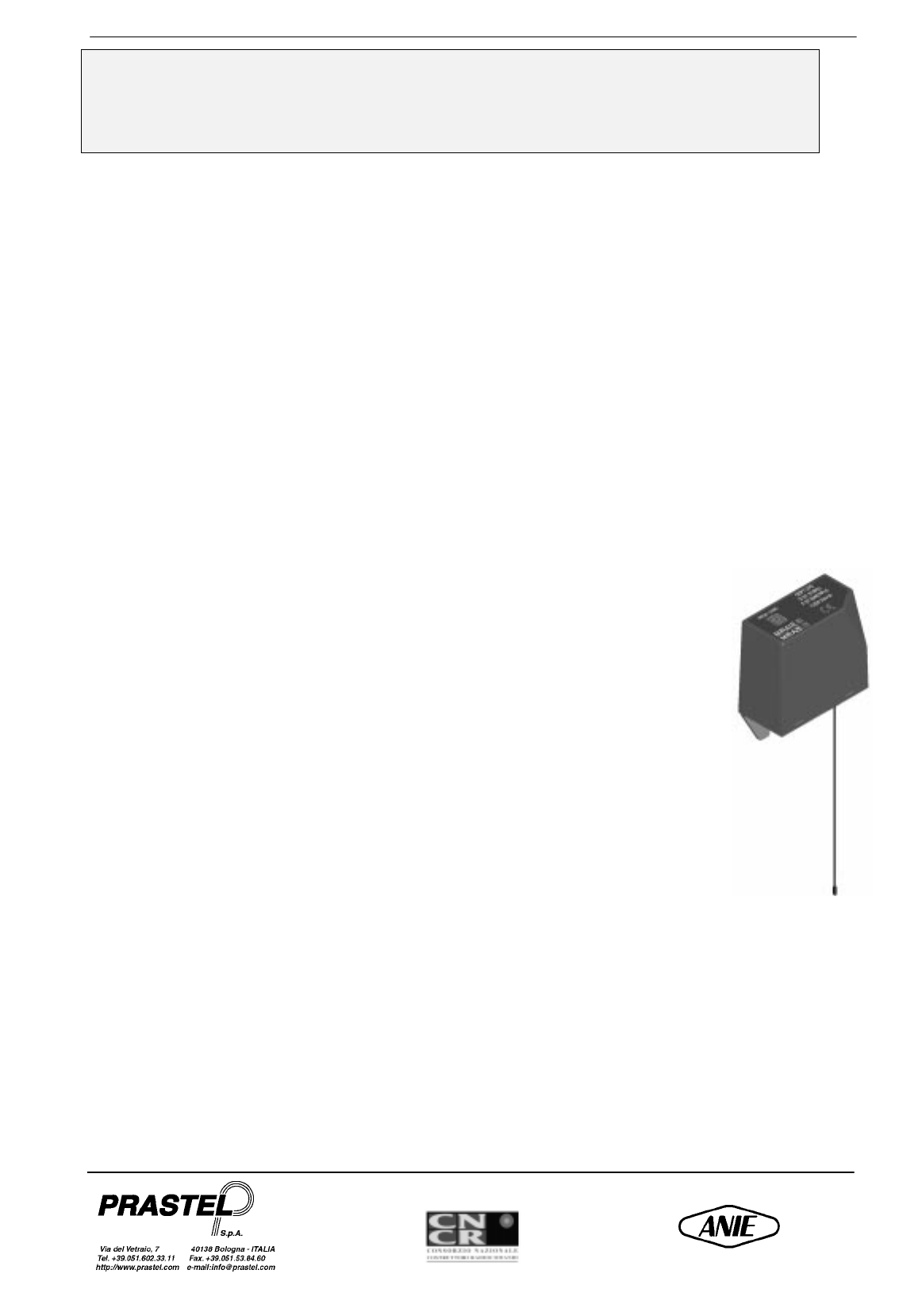
1. GENERAL INFORMATION
These receivers integrate the functions of standard Multipass and Multipass Roll code receivers and decoders.
They feature a storage capacity of up to 200 different codes generated by transmitters of the Multipass and
Multipass Roll family at 433.920 MHz (M/RA1E - M/RA2E).
2. ROLLING CODING
This type of coding affords extra security as it prevents the risk of code violation by interception or re-
transmission. It is based on the transmission of a batch of bits consisting of a fixed part (which is different for each
transmitter), of channel bits associated with the switch of the activated transmitter, and of a part which changes in
a pseudo-random manner (rolling code) in accordance with a proprietary Prastel algorithm. The configuration of
these latter bits changes unpredictably from one transmission to the following. The receiver memorises by self-
learning the fixed part of the code associated with each transmitter plus the relevant rolling code, updating the
latter upon each transmission. Transmitter recognition occurs only if the transmitted rolling code corresponds to
the 255 configurations subsequent to the last recognised transmission. Realignment and recognition of a
previously memorised transmitter which has overrun the permissible interval (an event which may occur for
example following on an excess of unrecognised transmissions or upon battery replacement) can however be
made by pressing and releasing the transmitter learning button. This procedure permits the system to check for
code correctness, while safeguarding the advantages afforded by the rolling code.
3. TECHNICAL FEATURES
Power supply 12 - 24 Vac/dc
Average consumption Stand-by: 20 mA with relay
energized: 45 mA
Reception frequency 433 MHz
Digital Code With a number of bits varying
from 40 to 54
Number of storable codes 200
Number of channels 1 (M/RA1E); 2 (M/RA2E)
Type of output Monostable, bistable
Output Relay
Contact rating 0,5 A @ 24 Vac/dc
Signals red LED
Working temperature range -10/+55 °C
Storage temperature -40/+85 °C
Receiver weight 250 g.
Receiver dimensions 77 x 80 x 38 mm
4. VOLTAGE SELECTION
Both the M/RA2E-M/RA1E receivers can operate at 24V and 12V ac/dc.
5. CODE PROGRAMMING AND DELETION
Entry and storage of a new code and deletion of the full code list can be made by acting on key P1, while deletion
of single user codes can be made using the GT/BASER portable terminal.
How to Program
• Power the receiver as specified.
• Press P1. The red LED lights up indicating that programming is in progress.
• Press any of the transmitter’s keys to make a transmission.
• The code will now be entered in the memory. While loading is in progress, LED will flash. Upon code being
stored, the LED stops flashing and becomes fixed. A new code can now be entered.
• Load the codes of all the transmitters by making a transmission with each of them.
MRA2E – MRA1E
ENGLISH
MRAE_V0
Member of: Associated
• Upon this operation being completed, press P1 again to exit from programming mode. The LED will go off. In
any case, the system will automatically exit from programming mode upon 10 seconds having elapsed since
last loading.
• Codes remain stored even if receiver is powered off.
Attention: Make a transmission within 10 seconds after pressing P1 as system will automatically exit from
programming mode after this time has elapsed if no transmission has been made.
To re-access programming mode, press P1 again.
Deletion of all codes
• Press and hold down key P1 until the red LED starts flashing.
• Press P1 again within 6 seconds to confirm deletion. Confirmation is signalled by the LED flashing more
rapidly.
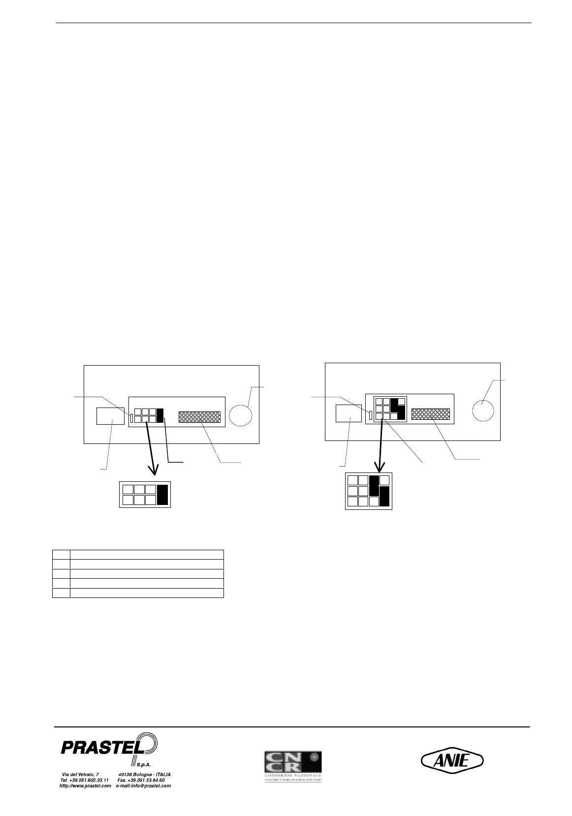
6. CHANNEL SELECTION AND RELAY OPERATING MODE
Set output as desired by means of jumper A (jumper A closed for monostable relay operation and jumper A open
for bistable relay operation). Note: Relay operating mode selection is not contemplated on the M/RA2E
receiver.
7. ANTENNA CONNECTION
The receivers may be connected to external antennas of corresponding frequencies by means of the appropriate
F-type female connectors.
The M/RA1E and M/RA2E receivers can instead be connected to ANT/433SD type antennas, to the wire
antenna provided or the like.
M/RA1E M/RA2E
ARelay operating mode selection
BF-type female antenna connector
CMicro-match for memory control
DChannel selection jumper
EPlug connector input
A
C
B
FIG.1
E
Output A
4 3 2 1 (Channel)
D
B
A
Output B
Output A
4 3 2 1 (Channels) FIG.2
E
C
D
MRA2E – MRA1E
ENGLISH
MRAE_V0
Member of: Associated
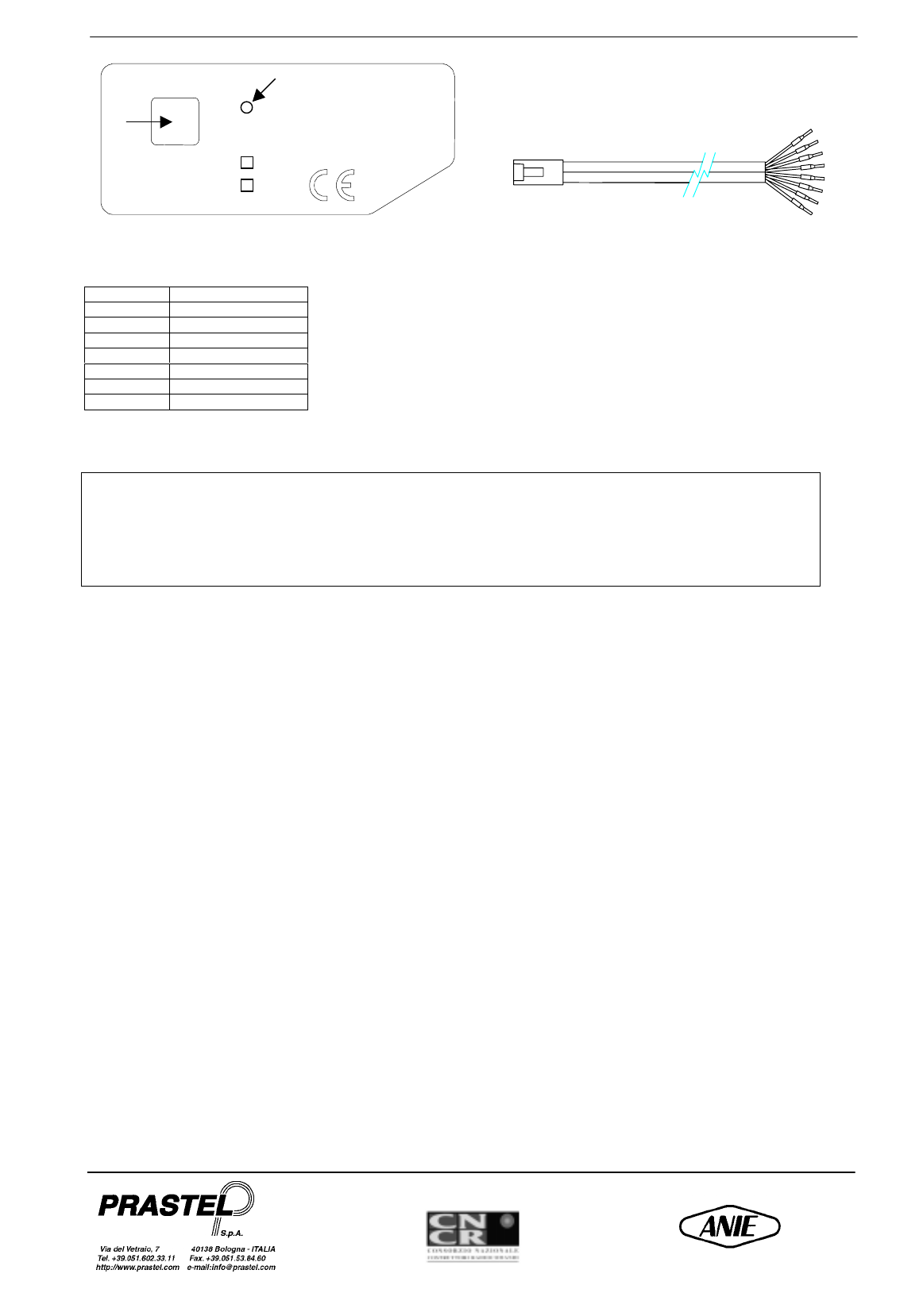
24 V BLUE
0ORANGE
12 V BLACK
N.C. out A RED
C out A GREEN
N.O. out A YELLOW
C out B BROWN
N.O. out B GREY
FCC ID: ON3MRAE
This device complies with part 15 of the FCC Rules. Operation is subject to the following two conditions:
(1) this device may not cause harmful interference, and (2) this device must accept any interference
received, including interference that may cause undesired operation.
This equipment has been tested and found to comply with the limits for a Class B digital device, pursuant to Part
15 of the FCC Rules. These limits are designed to provide reasonable protection against harmful interference in a
residential installation. This equipment generates, uses and can radiate radio frequency energy and, if not
installed and used in accordance with the instructions, may cause harmful interference to radio communications.
However, there is no guarantee that interference will not occur in a particular installation. If this equipment does
cause harmful interference to radio or television reception, which can be determined by turning the equipment
off and on, the user is encouraged to try to correct the interference by one or more of the following measures:
-Reorient or relocate the receiving antenna.
-Increase the separation between the equipment and receiver.
-Connect the equipment into an outlet on a circuit different from that to which the receiver is connected.
-Consult the dealer or an experienced radio/TV technician for help.
PR
OG/C
AN
C
CEPT LPD
D G1 31059J
F 97 0048 PPL0
12/24 Vac-dc
M/RA1E
M/RA2E
2m
P1
LED