Pratt and Whitney Engine Services FAST34E Engine Flight data Acquisition, Storage and Transmission User Manual DTU G 010 1 B
Pratt & Whitney Engine Services, Inc. Engine Flight data Acquisition, Storage and Transmission DTU G 010 1 B
Contents
- 1. User Manual Part 1
- 2. User Manual Part 2
- 3. User Manual Part 3
User Manual Part 1

P&W ENGINE SERVICES, INC. Data Transmission Unit DTU-G-010-1/B
Part 23 Aircraft Generation III Monitors
This Document is Subject to the Restrictions Contained on Cover Page
The export control classification with respect to this document is contained on the first page
DTU-G-010-1/B, Rev L, June 09, 2015 i of iv
REVISION HISTORY
Rev Status
of Sheets Rev LLLLLLLLLLLLLLLL
Sheet i ii iii iv 1 2 3 4 5 6 7 8 9 10 11 12
Rev LLLLLLLLLLLLLLLL
Sheet 13 14 15 16 17 18 19 20 21 22 23 24 25 26 27 28
Rev L L L L L L L L L
Sheet 29 30 31 32 33 34 35 36 37
LOG OF REVISIONS
REV.
NO ECO # DESCRIPTION DATE PAGES REVISED
- Initial Release 11/07/03
A Edit installation instructions for processor mounting and wiring
harness routing. Added WOW and power connection tables and
reference for mounting location
03/15/04 Cover, i, ii, iii, 4, 5, 6,
8, 10, 13, 14, 15, 18,
19, 20, 21
B Added ADAS+ Upgrade instructions, diode protection circuit,
revised power connections, and ADAS+ Upgrade wiring schematic 04/15/04 Cover, i, ii, iii, 2, 3, 9,
11, 12, 13, 14, 17, 19,
20, 23, 24, 25, 26, 28
C Added new mounting illustrations and revised Parts List 05/27/04 Cover, i, ii, iii, 4, 5, 6,
7, 8, 9
D Added new mounting configuration for LAN antenna, and
instructions for Installation Summary table, revised Parts List,
mounting bracket instructions, and harness installation instructions
06/07/04 Cover, i, ii, iii, 3, 4, 5,
9, 10, 11, 13, 14, 21, 22
E Revised wiring diagram for ADAS+ Upgrade Monitors and updated
photograph for antenna location on Raytheon model aircraft 06/28/04 Cover, i, ii, iii, 13, 23,
24, 25, 31
F 823 Update part numbers and add a kit for the ADAS+ installed on
Raytheon Models. Revise the ConXall connecter wiring instructions
for the download port and DTU Status lamp. Revise Installation
Caution regarding the length of wire from the protection device to the
power source.
06/03/05 Cover, i – iii, 2 – 32
G 859 Update figures B-2, B-3, and B4 to show correct configuration of the
double-stack bracket assembly. 06/14/06 Cover, i, 6, 7
H 962 Updated company name, address and logo. Updated formatting.
Corrected spelling and grammar. Updated wire numbers in text,
connection charts and schematics.
02/28/08 ALL
J 1008
1017
Add Instructions and Schematics for DTU and ADASdInterface.
Correct typographical errors. Remove LAN Antenna References. 03/01/10 ALL
K 1024 Update DTU RF Cable P/N in the Engine Harness Kit. Update
Raytheon 300 WOW Connection in the Connection Chart 05/04/10 Cover, i, 3, 30

P&W ENGINE SERVICES, INC. Data Transmission Unit DTU-G-010-1/B
Part 23 Aircraft Generation III Monitors
This Document is Subject to the Restrictions Contained on Cover Page
The export control classification with respect to this document is contained on the first page
DTU-G-010-1/B, Rev L, June 09, 2015 ii of iv
REV.
NO ECO # DESCRIPTION DATE PAGES REVISED
L 1228 Add DTU Kit for Cessna Caravan that have ADAS
d
installed.
Update wiring schematics. Update format of document footer 06/09/2015 ALL
Note: If the DTU Installation Instructions are revised, all operators will be provided with a copy of the
applicable revision. If you have a subscription with TurbineTracker
, you will be informed via
email of new revisions to this manual. In addition to this, P&W Engine Services maintains the
latest versions of all manuals in the Support Section of TurbineTracker
.
If you are not a subscriber to TurbineTracker
, you may call P&W Engine Services Customer
Support at 781-762-8600 for the latest revision.

P&W ENGINE SERVICES, INC. Data Transmission Unit DTU-G-010-1/B
Part 23 Aircraft Generation III Monitors
This Document is Subject to the Restrictions Contained on Cover Page
The export control classification with respect to this document is contained on the first page
DTU-G-010-1/B, Rev L, June 09, 2015 iii of iv
TABLE OF CONTENTS
1 P&W ENGINE SERVICES, INC. – GEN III MONITOR APPLICATION............................................................ 1
1.1 SCOPE...................................................................................................................................................................... 1
2 INSTALLATION AND MAINTENANCE PROCEDURES..................................................................................... 2
2.1 PARTS LIST.............................................................................................................................................................. 2
2.1.1 DTU by Parts Kits .............................................................................................................................................. 2
2.1.2 Components by Kit ............................................................................................................................................. 3
3 INSTALLATION – MECHANICAL........................................................................................................................... 8
3.1 SYSTEM PROCESSOR MOUNTING ............................................................................................................................. 8
3.2 DTU STATUS SWITCH/FAULT LAMP AND COMMUNICATIONS PORT...................................................................... 14
3.2.1 Status Switch/Fault Lamp................................................................................................................................. 14
3.2.2 Download Port ................................................................................................................................................. 15
3.3 ANTENNA MOUNTING ........................................................................................................................................... 15
3.4 HARNESS INSTALLATION ....................................................................................................................................... 16
3.4.1 J1 Harness Installation..................................................................................................................................... 17
3.4.2 GSM Antenna Cable Installation...................................................................................................................... 18
4 INSTALLATION - ELECTRICAL........................................................................................................................... 19
4.1 DTU STATUS LAMP AND COMMUNICATIONS PORT WIRING.................................................................................. 19
4.1.1 DTU Status Lamp Wiring ................................................................................................................................. 19
4.1.2 Download Port Connector Wiring.................................................................................................................... 21
4.2 AIRFRAME SENSORS.............................................................................................................................................. 23
4.2.1 On Ground (Weight-on-Wheels) Signal............................................................................................................ 23
4.3 ELECTRICAL POWER.............................................................................................................................................. 24
4.3.1 Battery Power / Ground Connection................................................................................................................ 24
4.3.2 Bus (Switched) Power Connection ................................................................................................................... 25
4.4 FINAL INSTALLATION NOTES................................................................................................................................. 25
5 HARNESS CONNECTOR SIGNAL PINOUTS....................................................................................................... 27
5.1 ACS CABLE J1, 37 PIN “A” KEYED CONNECTOR .................................................................................................. 27
5.2 DTU CONNECTION CHART – POWER AND RF LOCKOUT ....................................................................................... 30
5.2.1 Cessna Caravan Model 208 Series................................................................................................................... 30
5.2.2 Raytheon Model C90........................................................................................................................................ 30
5.2.3 Raytheon Models 200 & 200T.......................................................................................................................... 30
5.2.4 Raytheon Models 200CT, A200, A200C, & A200CT........................................................................................ 31
5.2.5 Raytheon Models B200C, B200CT, B200, B200T............................................................................................ 31
5.2.6 Raytheon Model 300 Series.............................................................................................................................. 31
5.2.7 Raytheon Model B300 Series............................................................................................................................ 32
5.2.8 Raytheon Model 1900 & 1900C ....................................................................................................................... 32
5.2.9 Raytheon Model 1900D.................................................................................................................................... 32
6 WIRING DIAGRAM .................................................................................................................................................. 33
6.1 DTU / ADASDINTERCONNECT SCHEMATIC .......................................................................................................... 33
6.2 DTU / ADAS+ INTERCONNECT SCHEMATIC (EXCEPT CESSNA CARAVAN)........................................................... 34
6.3 DTU / ADAS+ INTERCONNECT SCHEMATIC (CESSNA CARAVAN STC INSTALLATION)........................................ 35
6.4 DTU / ADAS+ INTERCONNECT SCHEMATIC (CESSNA CARAVAN FACTORY INSTALLATION)................................ 36
6.5 DTU / ADAS+ UPGRADE INTERCONNECT SCHEMATIC ......................................................................................... 37

P&W ENGINE SERVICES, INC. Data Transmission Unit DTU-G-010-1/B
Part 23 Aircraft Generation III Monitors
This Document is Subject to the Restrictions Contained on Cover Page
The export control classification with respect to this document is contained on the first page
DTU-G-010-1/B, Rev L, June 09, 2015 iv of iv
LIST OF FIGURES
FIGURE B- 1: DTU PROCESSOR................................................................................................................................................. 8
FIGURE B- 2: DTU/GEN III PROCESSOR TO BRACKET MOUNTING.......................................................................................... 10
FIGURE B- 3: “DOUBLE STACK” MOUNTING CONFIGURATION – HONEYCOMB/SANDWICH PANEL......................................... 10
FIGURE B- 4: “DOUBLE STACK” MOUNTING CONFIGURATION – METAL SKIN........................................................................ 11
FIGURE B- 5: STAND ALONE BRACKET (DPU-D-098-1) TO HONEYCOMB/SANDWICH PANEL (SIDE VIEW) ........................... 12
FIGURE B- 6: STAND ALONE BRACKET (DPU-D-098-1) TO METAL SKIN (SIDE VIEW) .......................................................... 13
FIGURE B- 7: DTU STATUS LAMP........................................................................................................................................... 14
FIGURE B- 8: DTU STATUS LAMP MOUNTING DIMENSIONS ................................................................................................... 14
FIGURE B- 9: GSM ANTENNA................................................................................................................................................. 15
FIGURE B- 10: GSM ANTENNA LOCATION.............................................................................................................................. 16
FIGURE B- 11: DTU STATUS LAMP CONNECTOR WIRING....................................................................................................... 19
FIGURE B- 12: DTU STATUS LAMP CONNECTOR WIRING (WITH ADASD).............................................................................. 20
FIGURE B- 13: DOWNLOAD PORT CONNECTOR TO DOWNLOAD PORT – ADAS+.................................................................... 21
FIGURE B- 14: DOWNLOAD PORT CONNECTOR TO GEN III MONITOR – ADAS+ ................................................................... 22
FIGURE B- 15: DOWNLOAD PORT CONNECTOR TO GEN III MONITOR – ADAS+ UPGRADE................................................... 22
FIGURE B- 16: WOW DIODE ORIENTATION............................................................................................................................ 23
FIGURE B- 17: AIRCRAFT BATTERY FINAL WIRING ................................................................................................................ 24
FIGURE B- 18: AIRCRAFT BUS FINAL WIRING......................................................................................................................... 25
FIGURE B- 19: DTU / ADASDWIRING SCHEMATIC ................................................................................................................ 33
FIGURE B- 20: DTU / ADAS+ WIRING SCHEMATIC (EXCEPT CESSNA CARAVAN) ................................................................. 34
FIGURE B- 21: DTU / ADAS+ WIRING SCHEMATIC (CESSNA CARAVAN STC INSTALLATION) .............................................. 35
FIGURE B- 22: DTU / ADAS+ WIRING SCHEMATIC (CESSNA CARAVAN FACTORY INSTALLATION) ...................................... 36
FIGURE B- 23: DTU / ADAS+ UPGRADE WIRING SCHEMATIC ............................................................................................... 37
LIST OF TABLES
TABLE B- 1: DTU CONNECTION CHART CESSNA CARAVAN MODEL 208 SERIES ................................................................... 30
TABLE B- 2: DTU CONNECTION CHART RAYTHEON MODEL C90 .......................................................................................... 30
TABLE B- 3: DTU CONNECTION CHART RAYTHEON MODEL 200 & 200T.............................................................................. 30
TABLE B- 4: DTU CONNECTION CHART RAYTHEON MODEL 200CT, A200, A200C, & A200CT........................................... 31
TABLE B- 5: DTU CONNECTION CHART RAYTHEON MODEL B200C, B200CT, B200, & B200T ........................................... 31
TABLE B- 6: DTU CONNECTION CHART RAYTHEON MODEL 300 SERIES ............................................................................... 31
TABLE B- 7: DTU CONNECTION CHART RAYTHEON MODEL B300 SERIES............................................................................. 32
TABLE B- 8: DTU CONNECTION CHART RAYTHEON MODEL 1900 & 1900C.......................................................................... 32
TABLE B- 9: DTU CONNECTION CHART RAYTHEON MODEL 1900D SERIES .......................................................................... 32

P&W ENGINE SERVICES, INC. Data Transmission Unit DTU-G-010-1/B
Part 23 Aircraft Generation III Monitors
This Document is Subject to the Restrictions Contained on Cover Page
The export control classification with respect to this document is contained on the first page
DTU-G-010-1/B, Rev L, June 09, 2015 1 of 37
1 P&W ENGINE SERVICES, INC. – GEN III MONITOR APPLICATION
1.1 Scope
The purpose of this document is to provide users of this product with P&W Engine Services approved
installation instructions for the Data Transmission Unit (DTU). Any deviation from the procedures described
within this document could result in a failure of the product to perform properly and could possibly result in
damage to other systems of the aircraft.
These instructions apply to the aircraft associated with existing Pratt & Whitney Engine Services, Inc.,
Generation III monitoring systems.

P&W ENGINE SERVICES, INC. Data Transmission Unit DTU-G-010-1/B
Part 23 Aircraft Generation III Monitors
This Document is Subject to the Restrictions Contained on Cover Page
The export control classification with respect to this document is contained on the first page
DTU-G-010-1/B, Rev L, June 09, 2015 2 of 37
2 INSTALLATION AND MAINTENANCE PROCEDURES
2.1 Parts List
For Pratt & Whitney Engine Services, Inc. – Generation III Monitors:
The parts listed below consist of the installation kits for the DTU used on Pratt & Whitney Engine Services, Inc.
Generation III monitors. Assembly kit numbers are listed in section 2.1.1 and individual components are
detailed by kit numbers in section 2.1.2.
2.1.1 DTU by Parts Kits
For ADASdMonitors Installed on Raytheon Models: Qty P/N DTU-K-010-22 Weight
Processor Assembly 1 DTU-K-089-2 2.00 Lbs.
Engine Harness Kit 1 DTU-K-090-5 2.40 Lbs.
Fault Lamp Assembly Kit 1 DTU-K-091-2 0.50 Lbs.
Antenna Kit 1 DTU-K-092-2 0.20 Lbs
Additional Installation Materials Kit 1 DTU-K-093-20 0.20 Lbs
For ADAS+ Monitors Installed on Raytheon Models: Qty P/N DTU-K-010-6 Weight
Processor Assembly 1 DTU-K-089-2 2.00 Lbs.
Engine Harness Kit 1 DTU-K-090-2 2.40 Lbs.
Fault Lamp Assembly Kit 1 DTU-K-091-2 0.50 Lbs.
Antenna Kit 1 DTU-K-092-2 0.20 Lbs
Additional Installation Materials Kit 1 DTU-K-093-5 0.20 Lbs.
For ADAS+ Monitors Installed on Cessna Models: Qty P/N DTU-K-010-2 Weight
Processor Assembly 1 DTU-K-089-2 2.00 Lbs.
Engine Harness Kit 1 DTU-K-090-2 2.40 Lbs.
Fault Lamp Assembly Kit 1 DTU-K-091-2 0.50 Lbs.
Antenna Kit 1 DTU-K-092-2 0.20 Lbs
Additional Installation Materials Kit 1 DTU-K-093-2 0.20 Lbs.
For ADASdMonitors Installed on Cessna Models: Qty P/N DTU-K-010-26 Weight
Processor Assembly 1 DTU-K-089-15 2.00 Lbs.
Engine Harness Kit 1 DTU-K-090-18 2.40 Lbs.
Fault Lamp Assembly Kit 1 DTU-K-091-2 0.50 Lbs.
Antenna Kit 1 DTU-K-092-2 0.20 Lbs
Additional Installation Materials Kit 1 DTU-K-093-21 0.20 Lbs.

P&W ENGINE SERVICES, INC. Data Transmission Unit DTU-G-010-1/B
Part 23 Aircraft Generation III Monitors
This Document is Subject to the Restrictions Contained on Cover Page
The export control classification with respect to this document is contained on the first page
DTU-G-010-1/B, Rev L, June 09, 2015 3 of 37
For ADAS+ Upgrade Monitors Only: Qty P/N DTU-K-010-3 Weight
Processor Assembly 1 DTU-K-089-2 2.00 Lbs.
Engine Harness Kit 1 DTU-K-090-2 2.40 Lbs.
Fault Lamp Assembly Kit 1 DTU-K-091-2 0.50 Lbs.
Antenna Kit 1 DTU-K-092-2 0.20 Lbs
Additional Installation Materials Kit 1 DTU-K-093-3 0.10 Lbs.
2.1.2 Components by Kit
For ADASdMonitors Installed on Raytheon Models:
PROCESSOR ASSEMBLY KIT DTU-K-089-2
Processor, Standalone DTU-A-012-1 Qty 1
Bracket, Mounting (Dual Assembly) DPU-D-080-1 Qty 1
Plate Bracket Assembly DPU-A-082-1 Qty 1
Bracket, Low Profile Mntg (Stand Alone) DPU-D-098-1 Qty 1
Shock Mounts, Lord 990-00020 Qty 4
Washer, Processor Mount 920-00006 Qty 4
Nut, Locking, Processor Mount MS21042-06 Qty 4
Screw, Mount MS35207-261 Qty 10
Insert NAS1836-3-09 Qty 6
Strap, Ground DPU-C-050-1 Qty 1
FAULT LAMP ASSEMBLY DTU-K-091-2
Assy., Split Lamp ADAS-A-011-1 Qty 1
Lens, Switch, Dual Lamp, DTU DTU-D-082-1 Qty 1
Connector, 6 Pin Female 400-00026 Qty 1
ENGINE HARNESS KIT DTU-K-090-5
Cable Assembly, DTU ACS, J1 DAAS-C-040-1 Qty 1
RF, DTU, Rt. Angle-Straight DTU-C-078-1 Qty 1
Cable RF, DTU, 2X Rt. Angle DTU-C-084-3 Qty 1
ANTENNA KIT DTU-K-092-2
Antenna, GSM DTU-D-094-1 Qty 1
Conn, Dust Cap, SMA Male 400-00136 Qty 1
ADDITIONAL MATERIAL INSTALLATION KIT DTU-K-093-20
Mntg Plate DTU Fault Lamp/Dnld Port DTU-D-104-1 Qty 1
SPACER, NYLON #6 940-00015 Qty 4
Bracket, Antenna DTU-D-106-1 Qty 1
Plug, Finishing 9/16” 990-00121 Qty 1

P&W ENGINE SERVICES, INC. Data Transmission Unit DTU-G-010-1/B
Part 23 Aircraft Generation III Monitors
This Document is Subject to the Restrictions Contained on Cover Page
The export control classification with respect to this document is contained on the first page
DTU-G-010-1/B, Rev L, June 09, 2015 4 of 37
For ADAS+ Monitors Installed on Raytheon Models:
PROCESSOR ASSEMBLY KIT DTU-K-089-2
Processor, Standalone DTU-A-012-1 Qty 1
Bracket, Mounting (Dual Assembly) DPU-D-080-1 Qty 1
Plate Bracket Assembly DPU-A-082-1 Qty 1
Bracket, Low Profile Mntg (Stand Alone) DPU-D-098-1 Qty 1
Shock Mounts, Lord 990-00020 Qty 4
Washer, Processor Mount 920-00006 Qty 4
Nut, Locking, Processor Mount MS21042-06 Qty 4
Screw, Mount MS35207-261 Qty 10
Insert NAS1836-3-09 Qty 6
Strap, Ground DPU-C-050-1 Qty 1
FAULT LAMP ASSEMBLY DTU-K-091-2
Assy., Split Lamp ADAS-A-011-1 Qty 1
Lens, Switch, Dual Lamp, DTU DTU-D-082-1 Qty 1
Connector, 6 Pin Female 400-00026 Qty 1
ENGINE HARNESS KIT DTU-K-090-2
Cable Assembly, DTU ACS, J1 DTU-C-075-1 Qty 1
RF, DTU, Rt. Angle-Straight DTU-C-078-1 Qty 1
Cable RF, DTU, 2X Rt. Angle DTU-C-084-1 Qty 1
ANTENNA KIT DTU-K-092-2
Antenna, GSM DTU-D-094-1 Qty 1
Conn, Dust Cap, SMA Male 400-00136 Qty 1
ADDITIONAL MATERIAL INSTALLATION KIT DTU-K-093-5
Fuse, 1.0 Amp 990-00033 Qty 2
Fuse Holder DPU-C-057-1 Qty 2
Connector, 6 Pin Male 400-00027 Qty 1
Connector, 6 Pin Female 400-00026 Qty 1
Velcro® 990-00079 Qty 2 Ft
Diode 300-00034 Qty 2
Mntg Plate DTU Fault Lamp/Dnld Port DTU-D-104-1 Qty 1
SPACER, NYLON #6 940-00015 Qty 4
Bracket, Antenna DTU-D-106-1 Qty 1

P&W ENGINE SERVICES, INC. Data Transmission Unit DTU-G-010-1/B
Part 23 Aircraft Generation III Monitors
This Document is Subject to the Restrictions Contained on Cover Page
The export control classification with respect to this document is contained on the first page
DTU-G-010-1/B, Rev L, June 09, 2015 5 of 37
For ADAS+ Monitors Installed on Cessna Models:
PROCESSOR ASSEMBLY KIT DTU-K-089-2
Processor, Standalone DTU-A-012-1 Qty 1
Bracket, Mounting (Dual Assembly) DPU-D-080-1 Qty 1
Plate Bracket Assembly DPU-A-082-1 Qty 1
Bracket, Low Profile Mntg (Stand Alone) DPU-D-098-1 Qty 1
Shock Mounts, Lord 990-00020 Qty 4
Washer, Processor Mount 920-00006 Qty 4
Nut, Locking, Processor Mount MS21042-06 Qty 4
Screw, Mount MS35207-261 Qty 10
Insert NAS1836-3-09 Qty 6
Strap, Ground DPU-C-050-1 Qty 1
FAULT LAMP ASSEMBLY DTU-K-091-2
Assy., Split Lamp ADAS-A-011-1 Qty 1
Lens, Switch, Dual Lamp, DTU DTU-D-082-1 Qty 1
Connector, 6 Pin Female 400-00026 Qty 1
ENGINE HARNESS KIT DTU-K-090-2
Cable Assembly, DTU ACS, J1 DTU-C-075-1 Qty 1
RF, DTU, Rt. Angle-Straight DTU-C-078-1 Qty 1
Cable RF, DTU, 2X Rt. Angle DTU-C-084-1 Qty 1
ANTENNA KIT DTU-K-092-2
Antenna, GSM DTU-D-094-1 Qty 1
Conn, Dust Cap, SMA Male 400-00136 Qty 1
ADDITIONAL MATERIAL INSTALLATION KIT DTU-K-093-2
Fuse, 1.0 Amp 990-00033 Qty 2
Fuse Holder DPU-C-057-1 Qty 2
Connector, 6 Pin Male 400-00027 Qty 1
Connector, 6 Pin Female 400-00026 Qty 1
Velcro® 990-00079 Qty 2 Ft
Diode 300-00034 Qty 2
Mntg Plate DTU Fault Lamp/Dnld Port DTU-D-104-1 Qty 1

P&W ENGINE SERVICES, INC. Data Transmission Unit DTU-G-010-1/B
Part 23 Aircraft Generation III Monitors
This Document is Subject to the Restrictions Contained on Cover Page
The export control classification with respect to this document is contained on the first page
DTU-G-010-1/B, Rev L, June 09, 2015 6 of 37
For ADASdMonitors Installed on Cessna Models:
PROCESSOR ASSEMBLY KIT DTU-K-089-15
Processor, Standalone DTU-A-012-1 Qty 1
Bracket, Low Profile Mntg (Stand Alone) DPU-D-098-1 Qty 1
Shock Mounts, Lord 990-00020 Qty 4
Washer, Processor Mount 920-00006 Qty 4
Nut, Locking, Processor Mount MS21042-06 Qty 4
Screw, Mount MS35207-261 Qty 10
Strap, Ground DPU-C-050-1 Qty 1
FAULT LAMP ASSEMBLY DTU-K-091-2
Assy., Split Lamp ADAS-A-011-1 Qty 1
Lens, Switch, Dual Lamp, DTU DTU-D-082-1 Qty 1
Connector, 6 Pin Female 400-00026 Qty 1
ENGINE HARNESS KIT DTU-K-090-18
Cable Assembly, DTU ACS, J1 DAAS-C-040-2 Qty 1
Cable RF, DTU, 2X Rt. Angle DTU-C-084-1 Qty 1
ANTENNA KIT DTU-K-092-2
Antenna, GSM DTU-D-094-1 Qty 1
Conn, Dust Cap, SMA Male 400-00136 Qty 1
ADDITIONAL MATERIAL INSTALLATION KIT DTU-K-093-21
Connector, 6 Pin Male 400-00027 Qty 1
Connector, 6 Pin Female 400-00026 Qty 1
Velcro® 990-00079 Qty 2 Ft
Mntg Plate DTU Fault Lamp/Dnld Port DTU-D-104-1 Qty 1
Plug, Finishing 9/16” 990-00121 Qty 1
Terminal Ring #10 MS25036-103 Qty 1
Rivet Nut NAS1329A3K80 Qty 8

P&W ENGINE SERVICES, INC. Data Transmission Unit DTU-G-010-1/B
Part 23 Aircraft Generation III Monitors
This Document is Subject to the Restrictions Contained on Cover Page
The export control classification with respect to this document is contained on the first page
DTU-G-010-1/B, Rev L, June 09, 2015 7 of 37
For ADAS+ Upgrade Monitors Only:
PROCESSOR ASSEMBLY KIT DTU-K-089-2
Processor, Standalone DTU-A-012-1 Qty 1
Bracket, Mounting (Dual Assembly) DPU-D-080-1 Qty 1
Plate Bracket Assembly DPU-A-082-1 Qty 1
Bracket, Low Profile Mntg (Stand Alone) DPU-D-098-1 Qty 1
Shock Mounts, Lord 990-00020 Qty 4
Washer, Processor Mount 920-00006 Qty 4
Nut, Locking, Processor Mount MS21042-06 Qty 4
Screw, Mount MS35207-261 Qty 10
Insert NAS1836-3-09 Qty 6
Strap, Ground DPU-C-050-1 Qty 1
FAULT LAMP ASSEMBLY DTU-K-091-2
Assy., Split Lamp ADAS-A-011-1 Qty 1
Lens, Switch, Dual Lamp, DTU DTU-D-082-1 Qty 1
Connector, 6 Pin Female 400-00026 Qty 1
ENGINE HARNESS KIT DTU-K-090-2
Cable Assembly, DTU ACS, J1 DTU-C-075-1 Qty 1
RF, DTU, Rt. Angle-Straight DTU-C-078-1 Qty 1
Cable RF, DTU, 2X Rt. Angle DTU-C-084-1 Qty 1
ANTENNA KIT DTU-K-092-1
Antenna, GSM DTU-D-094-1 Qty 1
Antenna, RF DTU-D-095-1 Qty 1
Conn, Adapter Jack to Jack 960-00048 Qty 1
ADDITIONAL MATERIAL INSTALLATION KIT DTU-K-093-3
Fuse, 1.0 Amp 990-00033 Qty 2
Fuse Holder DPU-C-057-1 Qty 2
Connector, 6 Pin Male 400-00027 Qty 1
Velcro® 990-00079 Qty 2 Ft
Diode 300-00034 Qty 2
Harness TWIN-C-080-1 Qty 1
Bracket, Antenna DTU-D-106-1 Qty 1
Mntg Plate DTU Fault Lamp/Dnld Port DTU-D-104-1 Qty 1
Spacer 940-00015 Qty 4
P&W ENGINE SERVICES, INC. Data Transmission Unit DTU-G-010-1/B
Part 23 Aircraft Generation III Monitors
This Document is Subject to the Restrictions Contained on Cover Page
The export control classification with respect to this document is contained on the first page
DTU-G-010-1/B, Rev L, June 09, 2015 8 of 37
3 INSTALLATION – MECHANICAL
3.1 System Processor Mounting
The system processor (Figure B- 1) may be remotely mounted. The processor will not require access during
normal operation. P&W Engine Services offers three mounting bracket options. For aircraft with ample space
in the location of the previously installed Generation III processor (IntelliStart+, SmartCycle+, ADASd,
ADAS+, and TrendCheck+), the utilization of the double stack bracket (DPU-D-080-1 and DPU-A-082-1) is
recommended. For aircraft with limited clearance, the low profile bracket (DPU-D-098-1) is recommended.
DPU-D-030-1 is the bracket utilized in ADAS+, SmartCycle+, and IntelliStart+ installations. DPU-D-082-1 is
the bracket utilized in the ADASdinstallation.
Figure B- 1: DTU Processor
Note: The aircraft and available space will determine how the DTU will be installed. With the supplied
mounting brackets the DTU can be mounted in two different configurations.
1. If the current location of the Gen III processor has sufficient space the DTU can me mounted
in the “Double stack” configuration. Refer to Figure B- 3 or Figure B- 4.
2. If the current location of the Gen III processor does not have sufficient space, the DTU can
me mounted in another location using the Low Profile Bracket (DPU-D-098-1). See Figure B-
5 or Figure B- 6. Refer to the applicable aircraft maintenance manual for specific
instructions regarding standard practices for structural mounting.
3. The location of the processor must be recorded in the Installation Summary Table provide in
Instructions for Continued Airworthiness, DTU-G-260-1/B, Section 7.1
INSTALLATION CAUTION:
If another area is used to mount the DTU, the area must have sufficient structural integrity to
support the unit. Sheet metal panels should be .025” thick, with material comparable or
stronger than 2024-T3 aluminum.
When installing in a sandwich panel, an undercut shall be made around the periphery of the
insert hole to spoil the core in the area immediately around the insert hole. The panel shall
be a minimum of .50” thick.
The area chosen must be inspected for any evidence of dents, contraction, cracking, and
deterioration of metal. Reference AC 43.13-2A, Chapters 1 & 2 for specific guidelines in
determining a mounting location.
The area chosen must allow full and free movement of any control system cables or tubes.
The control mechanisms must be able to operate over their complete range of movement.
The DTU processor is not certified to be mounted in the engine compartment.

P&W ENGINE SERVICES, INC. Data Transmission Unit DTU-G-010-1/B
Part 23 Aircraft Generation III Monitors
This Document is Subject to the Restrictions Contained on Cover Page
The export control classification with respect to this document is contained on the first page
DTU-G-010-1/B, Rev L, June 09, 2015 9 of 37
For
Bracket Mounting
Option 1
–
Double Stack
(except for ADAS
d
)
The system processors shall be mounted in accordance with the following procedure:
010 Remove the Gen III processor and its mounting bracket from the aircraft. Discard the original
mounting bracket.
020 Ensure that the original inserts securing the bracket to the honeycomb panel are NAS1836-3 or
equivalent.
030 For installations in a honeycomb/sandwich panel, using the supplied mounting bracket (DPU-A-
082-1) as a template, mark the location of the 2 additional mounting holes and drill to accommodate a
NAS1836-3 potted insert.
040 Install six (6) NAS1836-3 potted inserts in accordance with manufacturer’s instructions
050 For installations in a metal skin, using the supplied mounting bracket (DPU-A-082-1) as a template,
mark the location of the two (2) additional mounting holes and drill to accommodate a #10 screw.
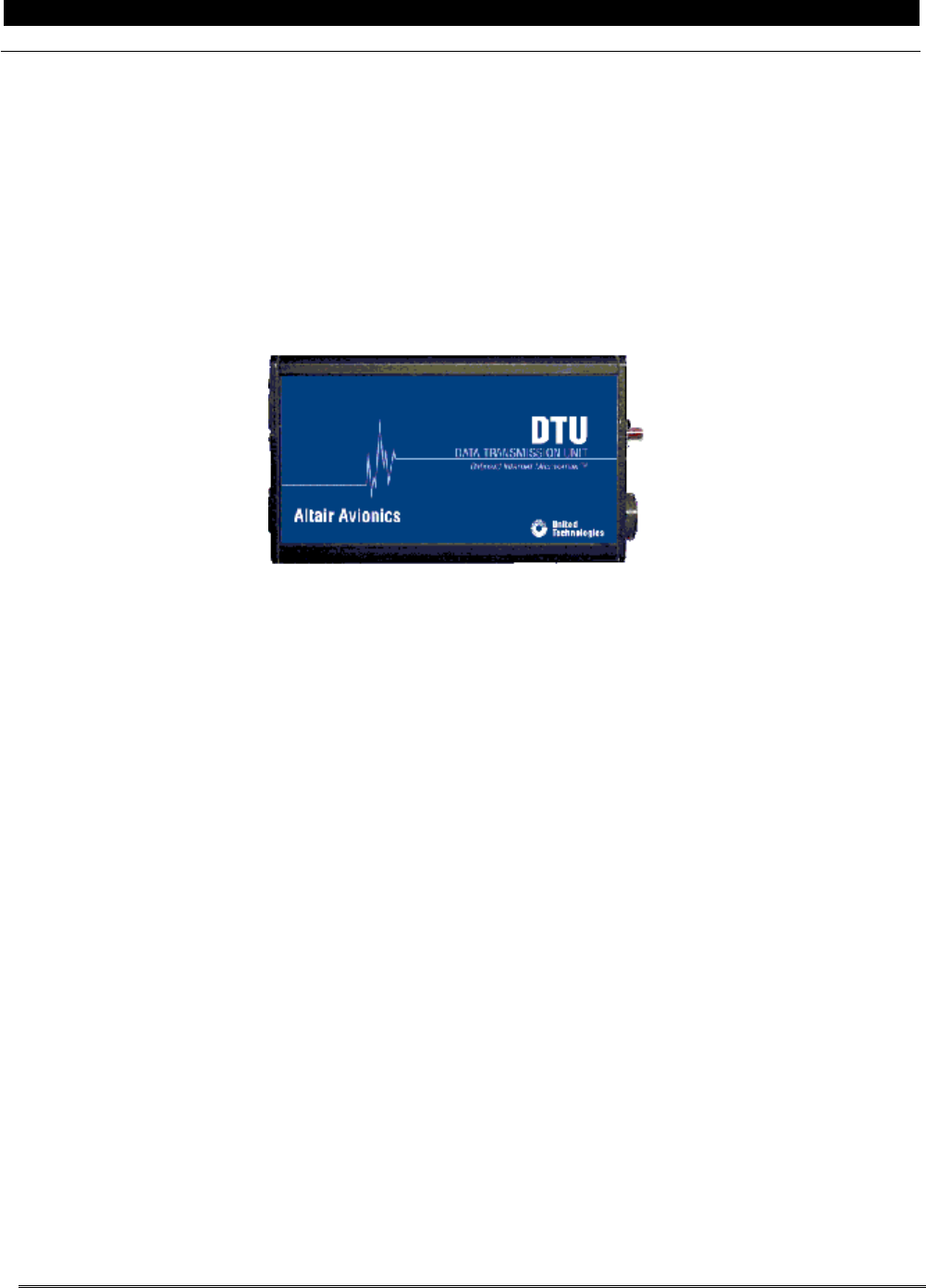
060 Assemble the DTU and Gen III processors to the mounting bracket as shown in Figure B- 2
INSTALLATION CAUTION:
Excessive torque on the processor-mounting studs can deform shock mounts. The locking
nut should be tightened to the point of contact with the shock mount.
070 Assemble the “Double Stack” mounting bracket and install the Gen III processor and the DTU
processor. Refer to applicable Figure B- 3 or Figure B- 4
080 Install ground strap DPU-C-050-2 between one of the processor-mounting studs and the aircraft
chassis for both the Gen III and DTU processors
090 Mount the “Double Stack” bracket containing the Gen III processor and the DTU to the aircraft using
the required hardware.
For
Bracket Mounting Option 1
–
Double Stack (ADAS
d
Only
)
The system processors shall be mounted in accordance with the following procedure:
010 Assemble the DTU to the “Double Stack” mounting bracket P/N DPU-D-080-1, as shown in Figure B-
2.
INSTALLATION CAUTION:
Excessive torque on the processor-mounting studs can deform shock mounts. The locking
nut should be tightened to the point of contact with the shock mount.
020 Attach the DTU and the “Double Stack” mounting bracket to the Gen III processor bracket using the
required hardware. Refer to applicable Figure B- 3 or Figure B- 4
030 Install ground strap DPU-C-050-2 between one of the processor-mounting studs and the aircraft
chassis for both the Gen III and DTU processors
P&W ENGINE SERVICES, INC. Data Transmission Unit DTU-G-010-1/B
Part 23 Aircraft Generation III Monitors
This Document is Subject to the Restrictions Contained on Cover Page
The export control classification with respect to this document is contained on the first page
DTU-G-010-1/B, Rev L, June 09, 2015 10 of 37
Figure B- 2: DTU/Gen III Processor to Bracket Mounting
Figure B- 3: “Double Stack” Mounting Configuration – Honeycomb/Sandwich Panel
P&W ENGINE SERVICES, INC. Data Transmission Unit DTU-G-010-1/B
Part 23 Aircraft Generation III Monitors
This Document is Subject to the Restrictions Contained on Cover Page
The export control classification with respect to this document is contained on the first page
DTU-G-010-1/B, Rev L, June 09, 2015 11 of 37
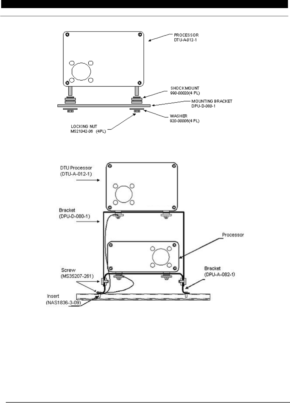
Figure B- 4: “Double Stack” Mounting Configuration – Metal Skin
P&W ENGINE SERVICES, INC. Data Transmission Unit DTU-G-010-1/B
Part 23 Aircraft Generation III Monitors
This Document is Subject to the Restrictions Contained on Cover Page
The export control classification with respect to this document is contained on the first page
DTU-G-010-1/B, Rev L, June 09, 2015 12 of 37
For
Bracket Mounting Option 2
–
Stand Alone
The system processor shall be mounted in accordance with the following procedure:
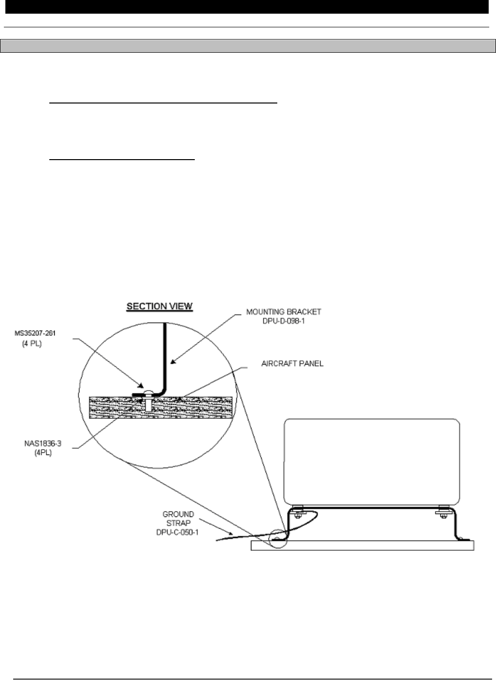
010 For installations in a honeycomb/sandwich panel, when a location has been determined for the
DTU processor, using the supplied mounting bracket (DPU-D-098-1) as a template, mark the
location of the four (4) holes and drill to accommodate a NAS1836-3 potted insert.
020 Install four (4) NAS1836-3 potted inserts in accordance with manufacturer’s instructions
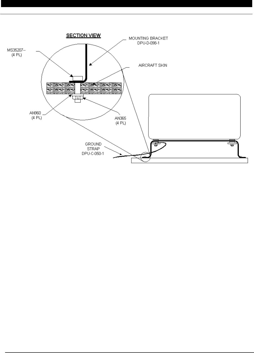
030 For installations in a metal skin, when a location has been determined for the DTU processor,
using the supplied mounting bracket (DPU-D-098-1) as a template, mark the location of the four (4)
mounting holes and drill to accommodate a #10 screw.
040 Assemble the DTU processor to the mounting bracket as shown in Figure B- 2
050 Install ground strap DPU-C-050-1 between one of the processor mounting studs and the aircraft
chassis.
060 Mount the DTU processor and bracket using the required hardware. Refer to applicable Figure B- 5
or Figure B- 6.
Figure B- 5: Stand Alone Bracket (DPU-D-098-1) to Honeycomb/Sandwich Panel (Side View)
P&W ENGINE SERVICES, INC. Data Transmission Unit DTU-G-010-1/B
Part 23 Aircraft Generation III Monitors
This Document is Subject to the Restrictions Contained on Cover Page
The export control classification with respect to this document is contained on the first page
DTU-G-010-1/B, Rev L, June 09, 2015 13 of 37
Figure B- 6: Stand Alone Bracket (DPU-D-098-1) to Metal Skin (Side View)
P&W ENGINE SERVICES, INC. Data Transmission Unit DTU-G-010-1/B
Part 23 Aircraft Generation III Monitors
This Document is Subject to the Restrictions Contained on Cover Page
The export control classification with respect to this document is contained on the first page
DTU-G-010-1/B, Rev L, June 09, 2015 14 of 37
3.2 DTU Status Switch/Fault Lamp and Communications Port
3.2.1 Status Switch/Fault Lamp
Assembly Notes
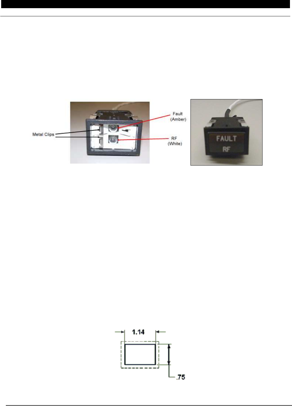
The DTU has a status switch / fault lamp, which consists of a rectangular push-to-test combination lamp
(Figure B- 7). The location of the DTU Status/Fault Lamp must be recorded in the Installation Summary Table
provide in Instructions for Continued Airworthiness, DTU-G-260-1/B, Section 7.1
Figure B- 7: DTU Status Lamp
INSTALLATION CAUTION:
The DTU Status lamp should be mounted in a location accessible to maintenance personnel.
If a suitable location is available, the supplied lamp mounting bracket (DTU-D-104-1) can be
used to remotely mount the DTU Status Lamp.
The DTU Status lamp is not certified to be mounted in the cockpit.
010 If the double stack configuration is used, the lamp can me mounted on the DTU processor mounting
bracket (DPU-D-080-1) using the supplied lamp mounting bracket (DTU-D-104-1).
020 Using the lamp mounting bracket as a template, mark and drill the three (3) #10 mounting holes on
the processor mounting bracket.
030 Secure the lamp mounting bracket to the processor mounting bracket.
040 Install the DTU Status Lamp into the bracket.
050 If the lamp cannot be mounted on the DTU processor mounting bracket, find a suitable location and
following Figure B- 8, mark and punch a 1.14 x 0.75 inch rectangular hole for mounting of the Status
Lamp.
060 Install the DTU Status Lamp into the panel.
Figure B- 8: DTU Status Lamp Mounting Dimensions
P&W ENGINE SERVICES, INC. Data Transmission Unit DTU-G-010-1/B
Part 23 Aircraft Generation III Monitors
This Document is Subject to the Restrictions Contained on Cover Page
The export control classification with respect to this document is contained on the first page
DTU-G-010-1/B, Rev L, June 09, 2015 15 of 37
3.2.2 Download Port
The DTU will wire into the existing download port installed in the aircraft from the previously installed
Generation III system.
3.3 Antenna Mounting
For ADAS+ Monitors Only (Except Raytheon Models):
The DTU incorporates a GSM antenna that will be mounted internal to the airframe. Velcro® is used to attach
the GSM antenna to the mounting surface. The location of the GSM antenna must be recorded in the
Installation Summary Table provide in Instructions for Continued Airworthiness, DTU-G-260-1/B, Section 7.1
INSTALLATION CAUTION:
The specific mounting location is important due to curvatures and uneven surfaces that can
be found on various aircraft. A flat surface is the desired GSM antenna mounting location.
The installer must ensure that the antenna is not mounted in a location totally encompassed
by metal
If the antenna is mounted in the cabin of the aircraft it must be securely fastened to the
aircraft to prevent their movement during a hard landing. The preferred method is to mount
the antenna in a secondary containment area.
010 The surface that will come in contact with the Velcro® tape must be free of paint, dust, oil, grease,
and other contamination prior to antenna installation. Clean the aircraft surface thoroughly.
020 Cut the supplied Velcro® tape to the length of the GSM antenna (Figure B- 9) and remove the
release film.
030 Firmly press the tape to the aircraft panel.
040 Cut the supplied Velcro® tape to the length of the GSM antenna and remove the release film.
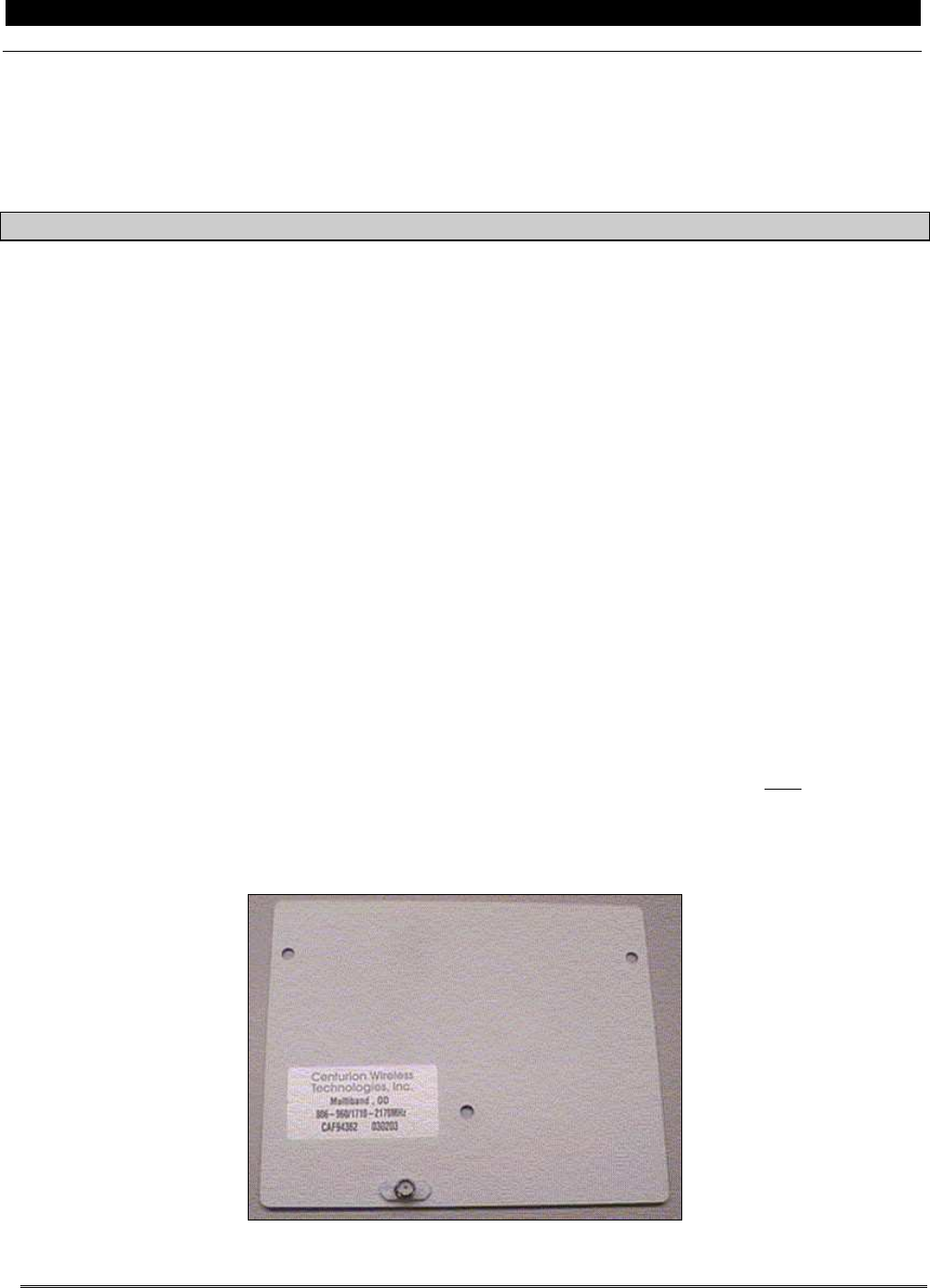
050 Firmly press the tape to the back of the GSM antenna. The front of the GSM antenna is identified by
the coaxial connector mounting and the identification label. Figure B- 9 shows the front of the GSM
antenna.
060 Mount GSM antenna to the Velcro® tape installed on the aircraft panel by firmly pressing the
antenna to the tape.
Figure B- 9: GSM Antenna
P&W ENGINE SERVICES, INC. Data Transmission Unit DTU-G-010-1/B
Part 23 Aircraft Generation III Monitors
This Document is Subject to the Restrictions Contained on Cover Page
The export control classification with respect to this document is contained on the first page
DTU-G-010-1/B, Rev L, June 09, 2015 16 of 37
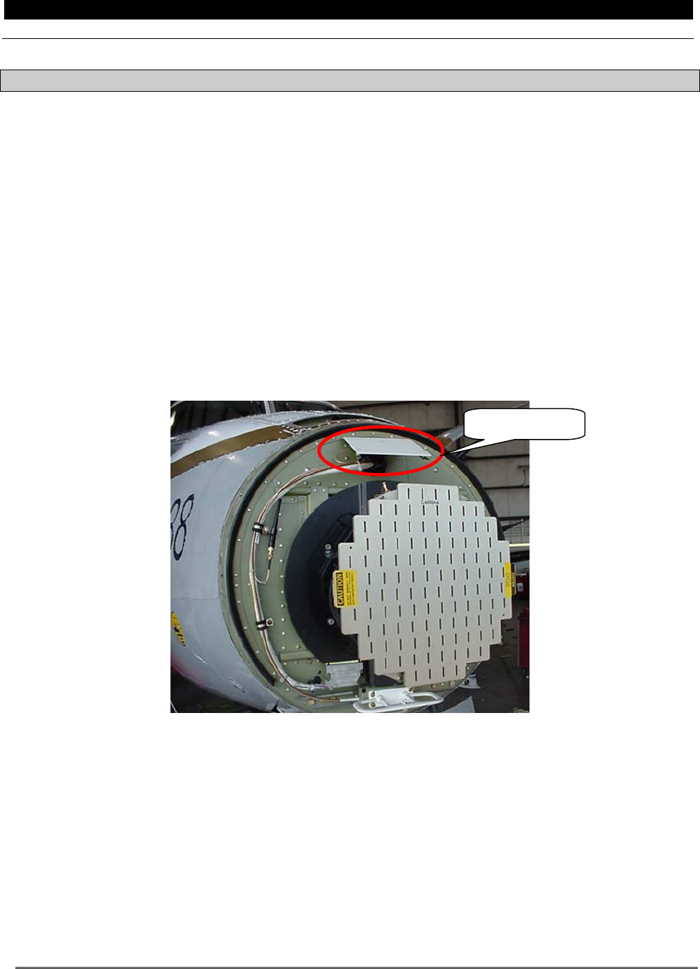
For All Gen III Monitors (Raytheon Models Only):
The DTU incorporates a GSM antenna that will be mounted internal to the airframe. A supplied mounting
bracket is used to attach the GSM antenna to the mounting surface.
INSTALLATION CAUTION:
The specific mounting location is important due to curvatures and uneven surfaces that can
be found on various aircraft.
The installer must ensure that the antenna are not mounted in a location totally
encompassed by metal
010 Remove the fiberglass nose cover from the nose of the aircraft
020 Locate the GSM antenna mounting bracket (DTU-D-106-1) as shown in Figure B- 10. Using the
bracket as a template mark and drill two mounting holes to accommodate a #10 screw.
030 Secure the GSM antenna to the mounting bracket using the supplied hardware and spacers.
040 Secure the mounting bracket assembly to the aircraft.
Figure B- 10: GSM Antenna Location
3.4 Harness Installation
INSTALLATION CAUTION:
Route all cables to follow existing wiring harnesses. Ensure that all cables and individual wires do not
interfere with any control cables. Secure all cables and wires with cable ties and where necessary, use
spiral tubing to protect wires from chaffing and abrasion. Do not secure cables to any existing power
cable.
Avoid sharp bends and routing RF cable near high energy sources
GSM Antenna

P&W ENGINE SERVICES, INC. Data Transmission Unit DTU-G-010-1/B
Part 23 Aircraft Generation III Monitors
This Document is Subject to the Restrictions Contained on Cover Page
The export control classification with respect to this document is contained on the first page
DTU-G-010-1/B, Rev L, June 09, 2015 17 of 37
3.4.1 J1 Harness Installation
For ADASdMonitors Only:
010 Connect the J1 harness to the J1 connector on the DTU processor.
020 Disconnect the existing 10 Pin Lemo connector (J2) from the ADASd. Route the DAAS-C-040
(10 pin Lemo connector “male”) cable from the DTU and connect to the ADASd(J2).
030 Route the AAB49B24 cable (10 pin Lemo connector “female”) to the ADASdand connect it to the
AAB40D24 cable (10 pin Lemo connector “male”) that was previously removed from the ADASd.
040 Route the AAV39E24 cable to the DTU Status Lamp.
050 Route the AAD09A24 cable to airframe ground.
For ADAS+ Monitors Only:
010 Connect the J1 harness to the J1 connector on the DTU processor.
020 Route the AAV09B24 cable and connect the “WHT” wire to a source that has “Hot” battery power all
the time. The “WHT/BLU” wire is connected to aircraft ground. Refer to Section 5.2 for your specific
aircraft model wiring.
030 Route the AAV19A24 cable and connect the “WHT” wire to a source that has “Switched on” battery
power. Refer to Section 5.2 for your specific aircraft model wiring.
040 Route the AAD09A24 cable to a weight on wheels switch (WOW). Refer to Section 5.2 for your
specific aircraft model wiring.
NOTE: Cessna Caravan installations will connect this wire to aircraft ground per section 5.2.
050 Route the AAB49B24 cable coming from the DTU to the existing Download Port.
060 Disconnect the ConXall™connector from the existing Download Port to the Gen III processor and
connect the Download Port to the ConXall™connector on the AAB49B24 cable.
070 Route the AAB48C24 cable to the GEN III cable previously connected to the Download Port and
assemble the ConXall™of the AAB48C24 cable to the existing Gen III processor cable.
080 Route the AAV39D24 & AAV38A24 cables to the installed DTU Status Lamp.

P&W ENGINE SERVICES, INC. Data Transmission Unit DTU-G-010-1/B
Part 23 Aircraft Generation III Monitors
This Document is Subject to the Restrictions Contained on Cover Page
The export control classification with respect to this document is contained on the first page
DTU-G-010-1/B, Rev L, June 09, 2015 18 of 37
For ADAS+ Upgrade Monitors Only:
010 Connect the J1 harness to the J1 connector on the DTU processor.
020 Split the harness and route the AAV09B24 cable and connect the “WHT” wire to a source that has
“Hot” battery power all the time. The “WHT/BLU” wire is connected to aircraft ground.
030 Route the AAV19A24 cable and connect the “WHT” wire to a source that has “Switched on” battery
power.
040 Route the AAD09A24 cable to a weight on wheels switch (WOW).
050 Route the AAB49B24 and the AAB48C24 connector cables coming from the DTU processor to the
ADAS+ Upgrade processor.
060 Route the AAV39D24 cable to the installed DTU Status Lamp.
3.4.2 GSM Antenna Cable Installation
010 Connect the GSM antenna cable to the DTU processor GSM connection. Torque SMA Connector to
5 inch pounds or 56 N-cm. The GSM antenna cable is the one with a 90° connection on both ends.
020 Route the GSM cable (90° connector) to the GSM antenna. Torque SMA Connector to 5 inch
pounds or 56 N-cm.
P&W ENGINE SERVICES, INC. Data Transmission Unit DTU-G-010-1/B
Part 23 Aircraft Generation III Monitors
This Document is Subject to the Restrictions Contained on Cover Page
The export control classification with respect to this document is contained on the first page
DTU-G-010-1/B, Rev L, June 09, 2015 19 of 37
4 INSTALLATION - ELECTRICAL
4.1 DTU Status Lamp and Communications Port Wiring
4.1.1 DTU Status Lamp Wiring
Wiring Notes:
ConXall™connectors are installed in this and the next section. The following tools are recommended by the
vendor for use with these connectors (vendor P/Ns): Insertion Bit (356-20), Pin Removal Bit (356-201), Socket
Removal Bit (356-202), Handle (356-1), Crimp Tool (359-21), Locator (357-122). The vendor address is:
ConXall Corporation, 601 East Wildwood, Villa Park, IL 60181.
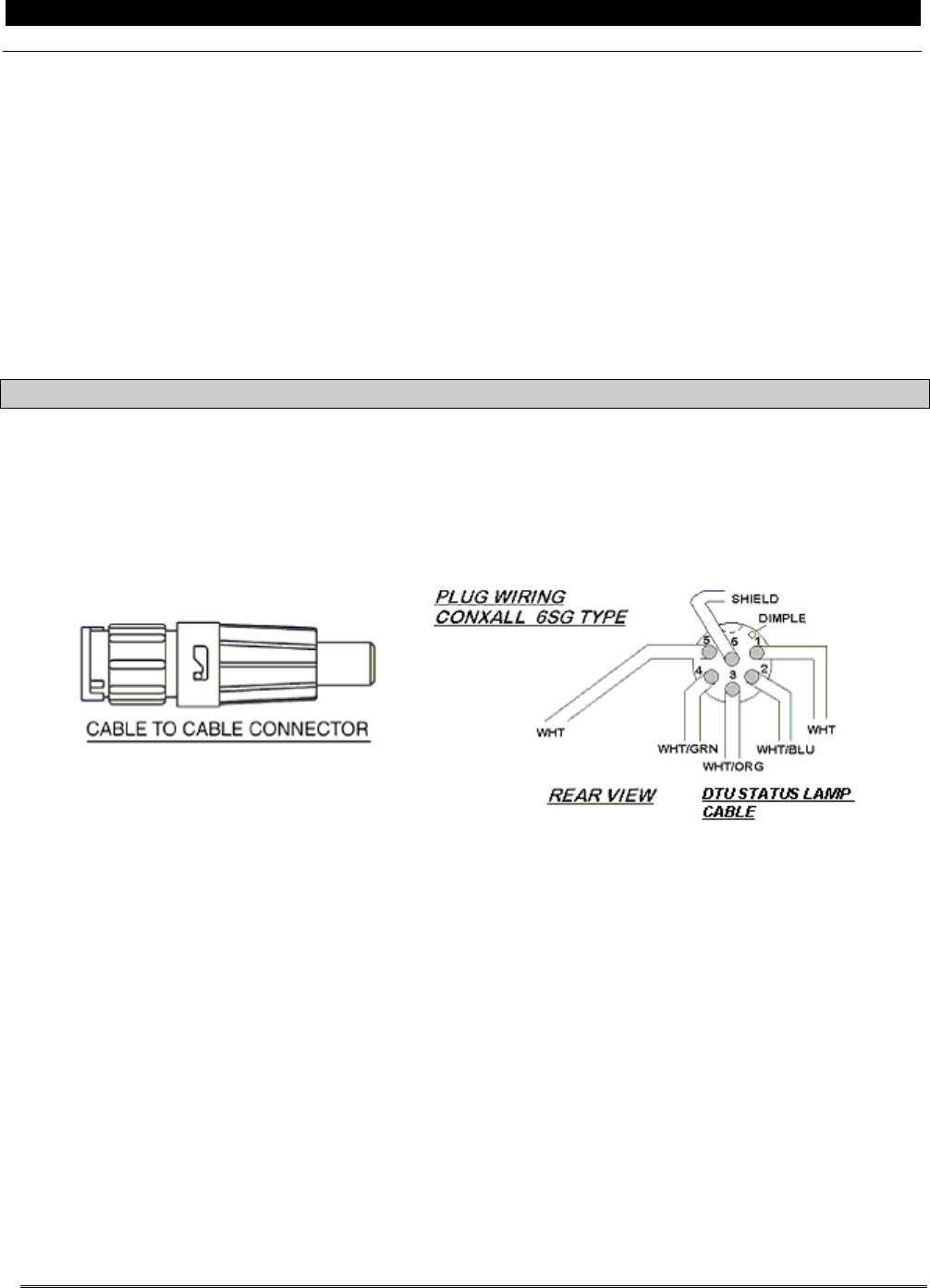
For All Gen III Monitors (except ADASd):
INSTALLATION CAUTION:
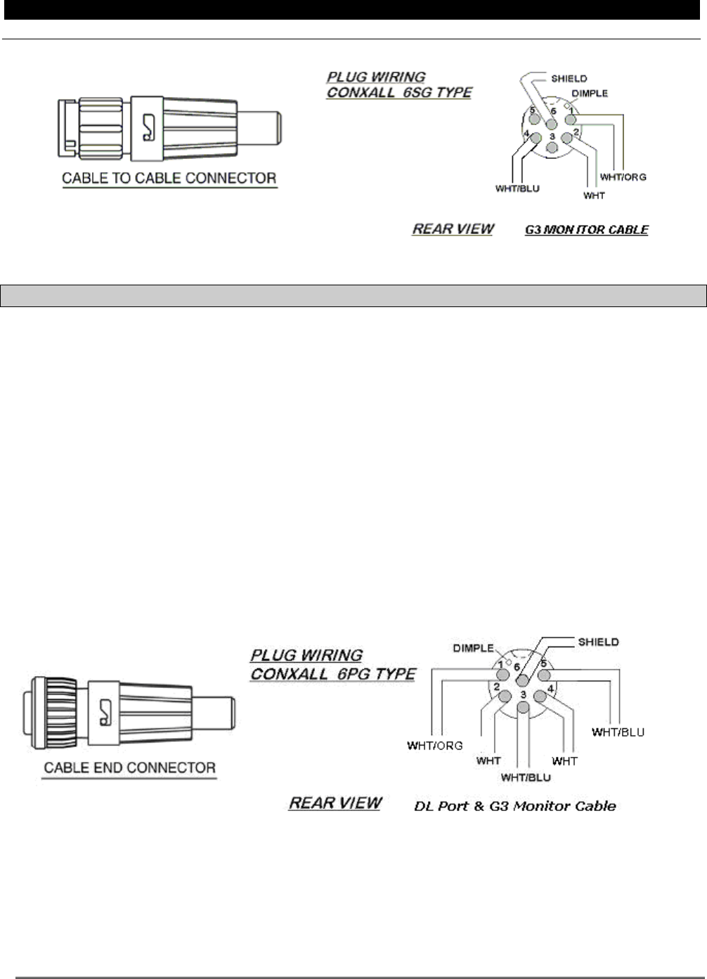
The DTU Status Lamp and the Download Port cables both use 6 pin connectors. The DTU
Status Lamp cable uses a socket connector (6SG type) and the Download Port cable uses a
pin connector (6PG type). Be sure to use the correct connector with the appropriate cable.
Figure B- 11: DTU Status Lamp Connector Wiring
Wiring Instructions
010 Trim the Ind Sw “AAV39D24” cable to length, and slide the correct ConXall™connector backshell
parts onto the cable.
020 Refer to the illustration Figure B- 11and connect the cable to the included ConXall™connector
using the socket configuration shown. Splice a short wire lead to the cable shield with a shrink-on
solder sleeve to make the Pin 6 shield connection.
030 Assemble the backshell to the connector, connect it to the lamp, and secure all wiring.
P&W ENGINE SERVICES, INC. Data Transmission Unit DTU-G-010-1/B
Part 23 Aircraft Generation III Monitors
This Document is Subject to the Restrictions Contained on Cover Page
The export control classification with respect to this document is contained on the first page
DTU-G-010-1/B, Rev L, June 09, 2015 20 of 37
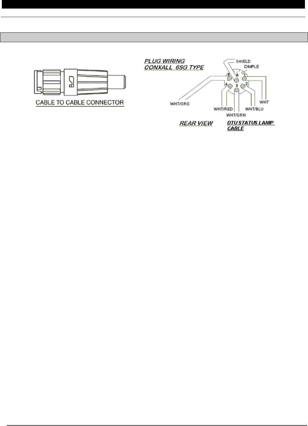
For ADASdMonitors:
Figure B- 12: DTU Status Lamp Connector Wiring (with ADASd)
Wiring Instructions
010 Trim the Ind Sw “AAV39E24” cable to length, and slide the correct ConXall™connector backshell
parts onto the cable.
020 Refer to the illustration Figure B- 12 and connect the cable to the included ConXall™connector
using the socket configuration shown. Splice a short wire lead to the cable shield with a shrink-on
solder sleeve to make the Pin 6 shield connection.
030 Assemble the backshell to the connector, connect it to the lamp, and secure all wiring.
P&W ENGINE SERVICES, INC. Data Transmission Unit DTU-G-010-1/B
Part 23 Aircraft Generation III Monitors
This Document is Subject to the Restrictions Contained on Cover Page
The export control classification with respect to this document is contained on the first page
DTU-G-010-1/B, Rev L, June 09, 2015 21 of 37
4.1.2 Download Port Connector Wiring
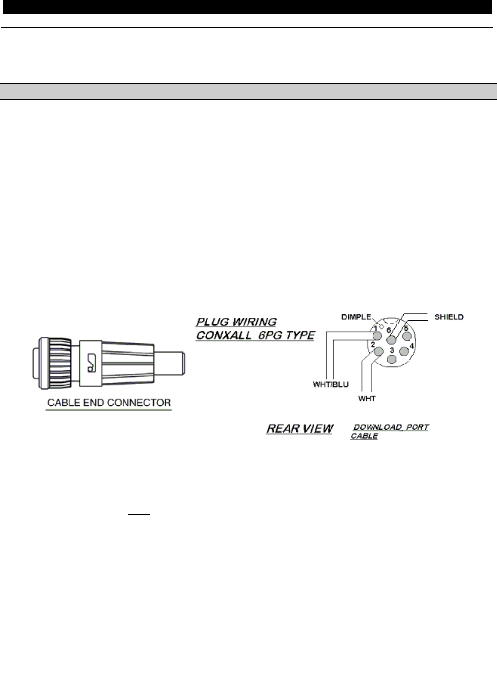
For ADAS+ Monitors Only:
INSTALLATION CAUTION:
The connections to the Download Port cables (DL PORT and G3 MONITOR) use a pin connector
(6PG type) and a socket connector (6SG type). Be sure to use the correct connector with the
appropriate cable.
Wiring Instructions
010 Trim the DL PORT “AAB49B24” connector cable to length, and slide the 6PG type ConXall™
connector backshell parts onto the cable. This connector will connect to the existing Download Port
connector mounted in the aircraft.
020 Refer to the illustration in Figure B- 13, and connect the cable to the included ConXall™plug
connector using the illustrated pin configuration. Pin 1 is identified by a dimple. Pins 3, 4, and 5
have no connection. Splice a short wire lead to the cable shield with a shrink-on solder sleeve to
make the Pin 6 shield connection
030 Assemble the backshell to the connector, connect it to the port, and secure all wiring.
Figure B- 13: Download Port Connector to Download Port – ADAS+
040 Trim the G3 MONITOR “AAB48C24” connector cable to length, and slide the 6SG type ConXall™
connector backshell parts onto the cable. This connector will connect to the existing ConXall™
connector coming from the GEN III processor
050 Refer to the illustration in Figure B- 14, and connect the cable to the included ConXall™plug
connector using the illustrated pin configuration. Pin 1 is identified by a dimple. Pins 3 and 5 have
no connection. Splice a short wire lead to the cable shield with a shrink-on solder sleeve to make
the Pin 6 shield connection
060 Assemble the backshell to the connector, connect it to the port, and secure all wiring.
P&W ENGINE SERVICES, INC. Data Transmission Unit DTU-G-010-1/B
Part 23 Aircraft Generation III Monitors
This Document is Subject to the Restrictions Contained on Cover Page
The export control classification with respect to this document is contained on the first page
DTU-G-010-1/B, Rev L, June 09, 2015 22 of 37
Figure B- 14: Download Port Connector to GEN III Monitor – ADAS+
For ADAS+ Upgrade Monitors Only:
INSTALLATION CAUTION:
The connections to the Download Port cables (DL PORT and G3 MONITOR) for the ADAS+
Upgrade use a single pin connector (6PG type).
010 Trim the DL PORT “AAB49B24” and the G3 MONITOR “AAB48C24” connector cable connector
cable to length, and slide the 6PG type ConXall™connector backshell parts onto the cable. This
connector will connect to the supplied harness ConXall™connector.
020 Refer to the illustration Figure B- 15 and connect the cable to the included ConXall™connector
using the socket configuration shown. Splice a short wire lead to the cable shields on both the DL
PORT “AAB49B24” and G3 MONITOR “AAB28C24” cables with a shrink-on solder sleeve to make
the Pin 6 shield connection.
030 Assemble the backshell to the connector, connect it to the lamp, and secure all wiring.
Figure B- 15: Download Port Connector to GEN III Monitor – ADAS+ Upgrade
P&W ENGINE SERVICES, INC. Data Transmission Unit DTU-G-010-1/B
Part 23 Aircraft Generation III Monitors
This Document is Subject to the Restrictions Contained on Cover Page
The export control classification with respect to this document is contained on the first page
DTU-G-010-1/B, Rev L, June 09, 2015 23 of 37
4.2 Airframe Sensors
4.2.1 On Ground (Weight-on-Wheels) Signal
For All Gen III Monitors (except ADASdand Cessna Models):
INSTALLATION CAUTION:
The “ON GROUND SW” cable is a single conductor shielded wire. Care must be taken to
strip back and secure shield to prevent possible shorting to the signal wire. Use plastic
spiral wrap where necessary to prevent chaffing and abrasion.
Weight on Wheels (WOW) is a secondary hardware lockout preventing the DTU from
transmitting in flight. The sensor requires an electrical ground, signaling that the aircraft is
not in flight.
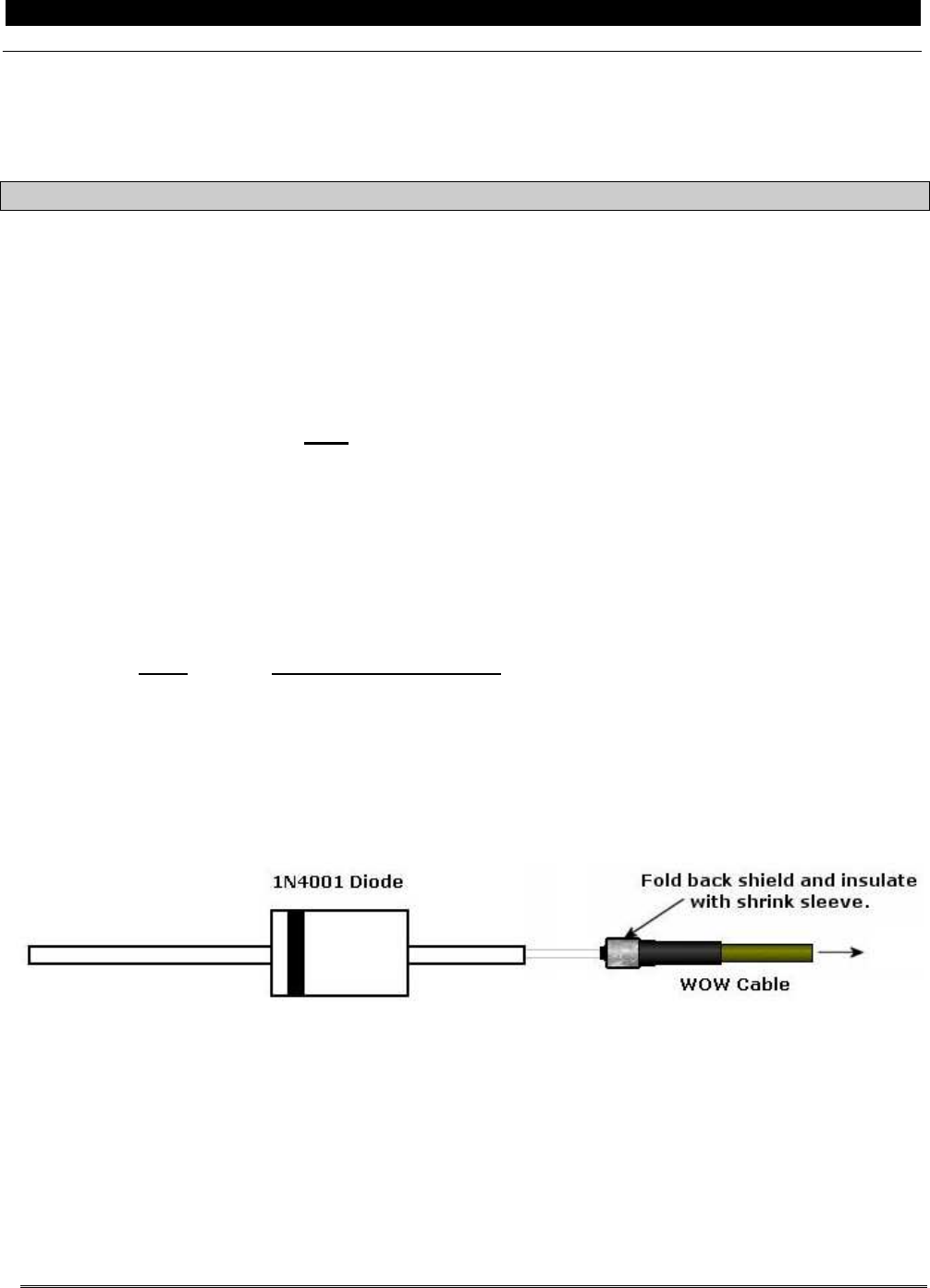
The “ON GROUND SW” cable uses a diode to protect the WOW circuit if the cable is shorted
to ground. This diode must be installed per the installation instructions and wiring diagram.
010 Trim the ON GROUND SW “AAD09A24” cable to length.
020 Splice the 1N4001 (300-00034) diode to the ON GROUND SW “AAD09A24” cable. Refer to Figure
B- 16 for the correct orientation of the diode. The diode must be located as close as possible to the
WOW connection point.
030 Splice to the Weight-on-Wheels connection. Refer to Section 5.2 for the applicable WOW
connection
Color Aircraft On Ground Signal
WHT “WOW” Switch
040 Secure all wiring.
Figure B- 16: WOW Diode Orientation
P&W ENGINE SERVICES, INC. Data Transmission Unit DTU-G-010-1/B
Part 23 Aircraft Generation III Monitors
This Document is Subject to the Restrictions Contained on Cover Page
The export control classification with respect to this document is contained on the first page
DTU-G-010-1/B, Rev L, June 09, 2015 24 of 37
4.3 Electrical Power
4.3.1 Battery Power / Ground Connection
For All Gen III Monitors (except ADASd):
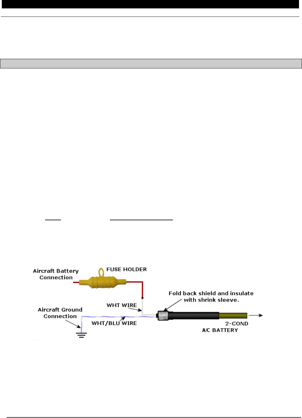
INSTALLATION CAUTION:
Power to the DTU must be available any time DC power is applied to the aircraft.
010 Following the illustration (Figure B- 17) connect the AC BATTERY “AAV09B24” white (positive)
wire to supplied fuse holder. Connect to the aircraft battery so that DC power is available at all
times to the processor. Refer to Section 5.2 for the applicable power connection.
020 Following the illustration (Figure B- 17) connect the AC BATTERY “AAV09B24” white/blue
(negative) wire to aircraft ground.
INSTALLATION CAUTION:
Ensure that any connection to aircraft power incorporates a minimal wire length from the
power source to the protection device, fuse or breaker. Recommended length is six (6)
inches or less.
Ensure that the wire is protected from shorting out against the airframe or any other sharp
objects.
Color Aircraft Power Source
WHT Aircraft Battery +
WHT/BLU Aircraft Ground –
030 Secure all wiring.
Figure B- 17: Aircraft Battery Final Wiring
P&W ENGINE SERVICES, INC. Data Transmission Unit DTU-G-010-1/B
Part 23 Aircraft Generation III Monitors
This Document is Subject to the Restrictions Contained on Cover Page
The export control classification with respect to this document is contained on the first page
DTU-G-010-1/B, Rev L, June 09, 2015 25 of 37
4.3.2 Bus (Switched) Power Connection
For All Gen III Monitors (except ADASd):
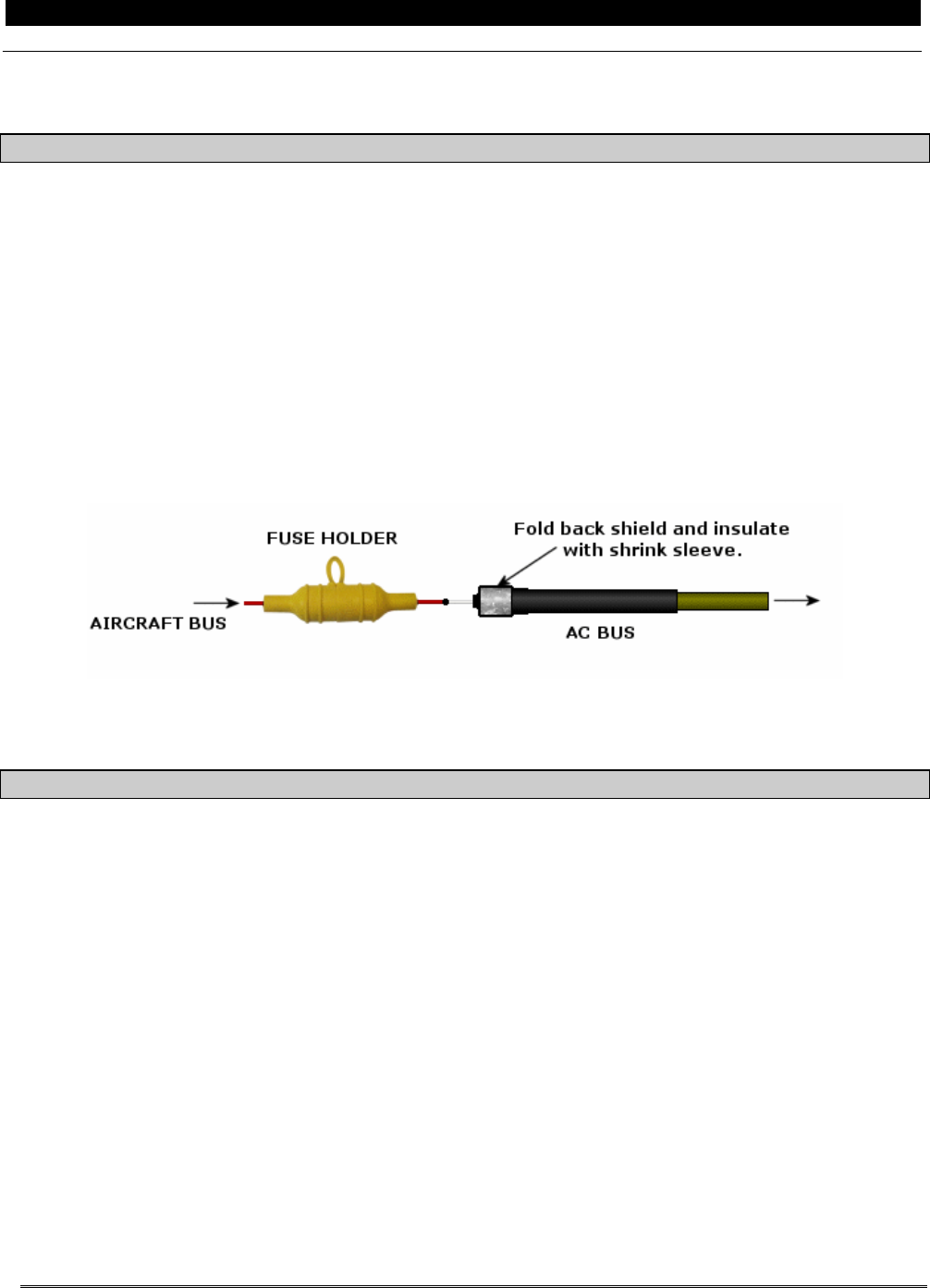
INSTALLATION CAUTION:
Ensure that any connection to aircraft power incorporates a minimal wire length from the
power source to the protection device, fuse or breaker. Recommended length is six (6)
inches or less.
Ensure that the wire is protected from shorting out against the airframe or any other sharp
objects.
010 Following the illustrations (Figure B- 18) connect the AC BUS “AAV19A24” wire to supplied fuse
holder. Connect to aircraft bus (switched) power. Refer to Section 5.2 for the applicable power
connection
020 Secure all wiring.
Figure B- 18: Aircraft Bus Final Wiring
4.4 Final Installation Notes
For ADAS+ Monitors Only:
010 Connect the cable from the DTU marked DL PORT “AAB49B24” to the existing Download Port
ConXall™connector that is mounted in the aircraft.
020 Connect the G3 MONITOR “AAB48C24” cable to the existing Download Port cable (from the GEN III
processor) at the ConXall™connector.
030 Connect the DTU STATUS LAMP “AAV39D24” connector to the DTU status lamp.
040 Route and secure all wires making sure engine / aircraft control movements will not be affected by
the DTU wiring. Properly dress any splices and shield terminations. Make sure wire harnesses will
not come in contact with sharp sections of the aircraft.
050 Install all aircraft panels.
060 Record the location of the processor, GSM antenna, and the DTU Status Lamp in the Installation
Summary Table provide in Instructions for Continued Airworthiness, DTU-G-260-1/B, Section 7.1

P&W ENGINE SERVICES, INC. Data Transmission Unit DTU-G-010-1/B
Part 23 Aircraft Generation III Monitors
This Document is Subject to the Restrictions Contained on Cover Page
The export control classification with respect to this document is contained on the first page
DTU-G-010-1/B, Rev L, June 09, 2015 26 of 37
For ADAS+ Upgrade Monitors Only:
010 Disconnect the cable to the COMM port on the ADAS+ Upgrade processor.
020 Connect P1 of the supplied harness (TWIN-C080-1) to the COMM port on the ADAS+ Upgrade
processor
030 Connect J1 of the supplied harness (TWIN-C-080-1) to the COMM cable that was removed in Step
020.
040 Connect the ConXall™connector on the supplied harness (TWIN-C-080-1) to the ConXall™
connector from the DTU processor.
050 Connect the DTU “STATUS LAMP” connector to the DTU status lamp.
060 Route and secure all wires making sure engine / aircraft control movements will not be affected by
the DTU wiring. Properly dress any splices and shield terminations. Make sure wire harnesses will
not come in contact with sharp sections of the aircraft.
070 Install all aircraft panels.
080 Record the location of the processor, GSM antenna, and the DTU Status Lamp in the Installation
Summary Table provide in Instructions for Continued Airworthiness, DTU-G-260-1/B, Section 7.1

P&W ENGINE SERVICES, INC. Data Transmission Unit DTU-G-010-1/B
Part 23 Aircraft Generation III Monitors
This Document is Subject to the Restrictions Contained on Cover Page
The export control classification with respect to this document is contained on the first page
DTU-G-010-1/B, Rev L, June 09, 2015 27 of 37
5 HARNESS CONNECTOR SIGNAL PINOUTS
5.1 ACS Cable J1, 37 Pin “A” Keyed Connector
INSTALLATION CAUTION:
Before making any wiring connections, verify all connection locations with the aircraft
manufacturer’s wiring diagram manuals.
Perform a continuity check on all wires before final connection.
Route all harnesses along existing harnesses wherever possible.
Cables may be marked with shrink-on labels near the terminal end. When you shorten a
cable behind a label, be sure to re-label it.
For ADASdMonitors Only:
Connector Harness
Pin Wire Color Signal Name Wired To
5 COND CABLE
J1-1 WHT 28V BUS 10 Pin Male Connector (Pin 9)
J1-36 WHT/ORG 28V AUX 10 Pin Male Connector (Pin 6)
J1-4 WHT/GRN 28V BAT 10 Pin Male Connector (Pin 5)
J1-32 WHT/RED RUN/CONF 10 Pin Male Connector (Pin 4)
J1-2 WHT/BLU 28V RTN 10 Pin Male Connector (Pin 3)
2 COND CABLE
J1-6, 8 WHT/BLU RS485A (–) 10 Pin Male Connector (Pin 2)
J1-5, 7 WHT RS485B (+) 10 Pin Male Connector (Pin 1)
2 COND CABLE
Shield Shield Shield 10 Pin Female Connector (Pin 5)
J1-16, 19 WHT/BLU RS485A (–) 10 Pin Female Connector (Pin 2)
J1-18, 17 WHT RS485B (+) 10 Pin Female Connector (Pin 1)
5 COND CABLE
Shield Shield Shield 6 Pin Female Connector (Pin 6)
J1-34 WHT/ORG LAMP 2 6 Pin Female Connector (Pin 5)
J1-34 WHT/RED SWITCH 6 Pin Female Connector (Pin 4)
J1-37 WHT/GRN LAMP 1 6 Pin Female Connector (Pin 3)
J1-2 WHT/BLU GROUND 6 Pin Female Connector (Pin 2)
J1-1 WHT LAMP PWR 6 Pin Female Connector (Pin 1)
1 COND CABLE
J1-15 WHT On-Ground Sw Aircraft Ground
Note: All shields are terminated to the backshell.

P&W ENGINE SERVICES, INC. Data Transmission Unit DTU-G-010-1/B
Part 23 Aircraft Generation III Monitors
This Document is Subject to the Restrictions Contained on Cover Page
The export control classification with respect to this document is contained on the first page
DTU-G-010-1/B, Rev L, June 09, 2015 28 of 37
For ADAS+ Monitors Only:
Connector Harness
Pin Wire Color Signal Name Wired To
3 COND CABLE
J1-5, 7 WHT/ORG ACS1– RS485B (+) Download Port Pin–1
J1-6, 8 WHT ACS1– RS485A (–) Download Port Pin–2
J1-32 WHT/BLU RUN/CONF Download Port Pin–4
4 COND CABLE
J1-23 WHT/GRN DIAG SWITCH Status Lamp Pin–4
J1-34 WHT INDIC SW LAMP 2 Status Lamp Pin–5
J1-37 WHT/ORG INDIC SW LAMP 1 Status Lamp Pin–3
J1-2 WHT/BLU GROUND Status Lamp Pin–2
1 COND CABLE
J1-1 WHT LAMP POWER Status Lamp Pin–1
2 COND CABLE
J1-19, 16 WHT RS485A (–) Conn Download Port Pin–2
J1-18, 17 WHT/BLU RS485B (+) Conn Download Port Pin–1
2 COND CABLE
J1-4 WHT Aircraft Battery Power + A/C Battery Positive
J1-3 WHT/BLU Aircraft Ground – A/C Battery Ground
1 COND CABLE
J1-1 WHT Aircraft Bus Power + A/C Switched Power
1 COND CABLE (Except Cessna Caravan)
J1-15 WHT On-Ground Sw Aircraft Weight-on-Wheels
1 COND CABLE (Cessna Caravan Only)
J1-15 WHT On-Ground Sw Aircraft Ground
Note: All shields are terminated to the backshell.

P&W ENGINE SERVICES, INC. Data Transmission Unit DTU-G-010-1/B
Part 23 Aircraft Generation III Monitors
This Document is Subject to the Restrictions Contained on Cover Page
The export control classification with respect to this document is contained on the first page
DTU-G-010-1/B, Rev L, June 09, 2015 29 of 37
For ADAS+ Upgrade Monitors Only:
Connector Harness
Pin Wire Color Signal Name Wired To
3 COND CABLE
J1-5, 7 WHT/ORG ACS1-RS485B (+) Download Port Pin–1
J1-6, 8 WHT ACS1-RS485A (–) Download Port Pin–2
J1-32 WHT/BLU RUN/CONF Download Port Pin–3
4 COND CABLE
J1-23 WHT/GRN DIAG SWITCH Status Lamp Pin–4
J1-34 WHT INDIC SW LAMP 2 Status Lamp Pin–5
J1-37 WHT/ORG INDIC SW LAMP 1 Status Lamp Pin–3
J1-2 WHT/BLU GROUND Status Lamp Pin–2
1 COND CABLE
J1-1 WHT LAMP POWER Status Lamp Pin–1
2 COND CABLE
J1-19, 16 WHT RS485A (–) Download Port Pin–4
J1-18, 17 WHT/BLU RS485B (+) Download Port Pin–5
2 COND CABLE
J1-4 WHT Aircraft Battery Power + A/C Battery Positive
J1-3 WHT/BLU Aircraft Ground – A/C Battery Ground
1 COND CABLE
J1-1 WHT Aircraft Bus Power + A/C Switched Power
1 COND CABLE
J1-15 WHT Aircraft Weight-On-Wheels Aircraft Weight-on-Wheels
Note: All shields are terminated to the backshell.

P&W ENGINE SERVICES, INC. Data Transmission Unit DTU-G-010-1/B
Part 23 Aircraft Generation III Monitors
This Document is Subject to the Restrictions Contained on Cover Page
The export control classification with respect to this document is contained on the first page
DTU-G-010-1/B, Rev L, June 09, 2015 30 of 37
5.2 DTU Connection Chart – Power and RF Lockout
For All Gen III Monitors (except ADASd):
5.2.1 Cessna Caravan Model 208 Series
Sensor Connection Chart
Wire Number Aircraft Component DTU Connector
A/C Bus AAV19A24 Relay K 3 J1
A1 Pin 1 WHT
A/C Battery AAV09B24 Relay K 3 J1
A2 Pin 4 WHT
Ground Pin 3 WHT/BLU
Aircraft
Ground AAD09A24 Aircraft Ground J1
Aircraft Ground Pin 15 WHT
Table B- 1: DTU Connection Chart Cessna Caravan Model 208 Series
5.2.2 Raytheon Model C90
Sensor Connection Chart
Wire Number Aircraft Component DTU Connector
A/C Bus AAV19A24 Main Bus J1
Supplied Circuit Breaker Pin 1 WHT
A/C Battery AAV09B24 Battery J1
A228 Box Assy. – Bat Bus Pin 4 WHT
Aircraft Ground Pin 3 WHT/BLU
WOW AAD09A24 WOW Cockpit Control J1
J125 – Pin 2 Pin 15 WHT
Table B- 2: DTU Connection Chart Raytheon Model C90
5.2.3 Raytheon Models 200 & 200T
Sensor Connection Chart
Wire Number Aircraft Component DTU Connector
A/C Bus AAV19A24 Main Bus J1
Supplied Circuit Breaker Pin 1 WHT
A/C Battery AAV09B24 Battery J1
W103 Bus Bar Panel Assy. Pin 4 WHT
Aircraft Ground Pin 3 WHT/BLU
WOW AAD09A24 WOW Cockpit Control J1
A100 – Pin 1 Pin 15 WHT
Table B- 3: DTU Connection Chart Raytheon Model 200 & 200T

P&W ENGINE SERVICES, INC. Data Transmission Unit DTU-G-010-1/B
Part 23 Aircraft Generation III Monitors
This Document is Subject to the Restrictions Contained on Cover Page
The export control classification with respect to this document is contained on the first page
DTU-G-010-1/B, Rev L, June 09, 2015 31 of 37
5.2.4 Raytheon Models 200CT, A200, A200C, & A200CT
Sensor Connection Chart
Wire Number Aircraft Component DTU Connector
A/C Bus AAV19A24 Main Bus J1
Supplied Circuit Breaker Pin 1 WHT
A/C Battery AAV09B24 Battery J1
W103 A228 Panel Assy. -
Battery Bus Power Pin 4 WHT
Aircraft Ground Pin 3 WHT/BLU
WOW AAD09A24 WOW Cockpit Control J1
A100 – Pin 1 Pin 15 WHT
Table B- 4: DTU Connection Chart Raytheon Model 200CT, A200, A200C, & A200CT
5.2.5 Raytheon Models B200C, B200CT, B200, B200T
Sensor Connection Chart
Wire Number Aircraft Component DTU Connector
A/C Bus AAV19A24 Main Bus J1
Supplied Circuit Breaker Pin 1 WHT
A/C Battery AAV09B24 Battery J1
W103 A228 Panel Assy.-
Battery Bus Power Pin 4 WHT
Aircraft Ground Pin 3 WHT/BLU
WOW AAD09A24 WOW Cockpit Control J1
A100 – Pin 1 Pin 15 WHT
Table B- 5: DTU Connection Chart Raytheon Model B200C, B200CT, B200, & B200T
5.2.6 Raytheon Model 300 Series
Sensor Connection Chart
Wire Number Aircraft Component DTU Connector
A/C Bus AAV19A24 Main Bus J1
Supplied Circuit Breaker Pin 1 WHT
A/C Battery AAV09B24 Battery J1
W1 A1 Circuit Breaker Box
Assy. Pin 4 WHT
Aircraft Ground Pin 3 WHT/BLU
WOW AAD09A24 WOW Cockpit Control J1
A100 – Pin 1 Pin 15 WHT
Table B- 6: DTU Connection Chart Raytheon Model 300 Series

P&W ENGINE SERVICES, INC. Data Transmission Unit DTU-G-010-1/B
Part 23 Aircraft Generation III Monitors
This Document is Subject to the Restrictions Contained on Cover Page
The export control classification with respect to this document is contained on the first page
DTU-G-010-1/B, Rev L, June 09, 2015 32 of 37
5.2.7 Raytheon Model B300 Series
Sensor Connection Chart
Wire Number Aircraft Component DTU Connector
A/C Bus AAV19A24 Main Bus J1
Supplied Circuit Breaker Pin 1 WHT
A/C Battery AAV09B24 Battery J1
W1 A1 Circuit Breaker Box
Assy. Pin 4 WHT
Aircraft Ground Pin 3 WHT/BLU
WOW AAD09A24 WOW Cockpit Control J1
A100 – Pin 1 Pin 15 WHT
Table B- 7: DTU Connection Chart Raytheon Model B300 Series
5.2.8 Raytheon Model 1900 & 1900C
Sensor Connection Chart
Wire Number Aircraft Component DTU Connector
A/C Bus AAV19A24 Main Bus J1
Supplied Circuit Breaker Pin 1 WHT
A/C Battery AAV09B24 Battery J1
W214 Bus Bar-Hot Battery Pin 4 WHT
Aircraft Ground Pin 3 WHT/BLU
WOW AAD09A24 WOW Cockpit Control J1
J125 – Pin 2 Pin 15 WHT
Table B- 8: DTU Connection Chart Raytheon Model 1900 & 1900C
5.2.9 Raytheon Model 1900D
Sensor Connection Chart
Wire Number Aircraft Component DTU Connector
A/C Bus AAV19A24 Main Bus J1
Supplied Circuit Breaker Pin 1 WHT
A/C Battery AAV09B24 Battery J1
P202 Pin 11 or 12 Pin 4 WHT
Aircraft Ground Pin 3 WHT/BLU
WOW AAD09A24 WOW Cockpit Control J1
J542 – Pin M Pin 15 WHT
Table B- 9: DTU Connection Chart Raytheon Model 1900D Series
P&W ENGINE SERVICES, INC. Data Transmission Unit DTU-G-010-1/B
Part 23 Aircraft Generation III Monitors
This Document is Subject to the Restrictions Contained on Cover Page
The export control classification with respect to this document is contained on the first page
DTU-G-010-1/B, Rev L, June 09, 2015 33 of 37
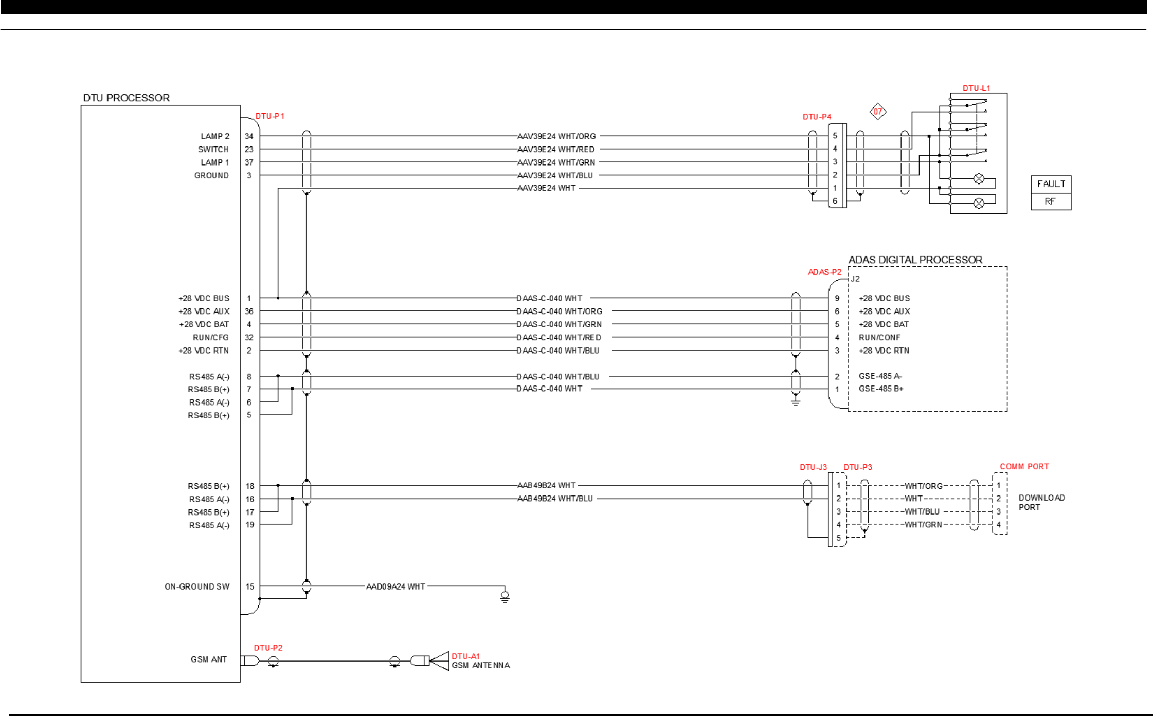
6 WIRING DIAGRAM
6.1 DTU / ADAS
d
Interconnect Schematic
Figure B- 19: DTU / ADASdWiring Schematic
P&W ENGINE SERVICES, INC. Data Transmission Unit DTU-G-010-1/B
Part 23 Aircraft Generation III Monitors
This Document is Subject to the Restrictions Contained on Cover Page
The export control classification with respect to this document is contained on the first page
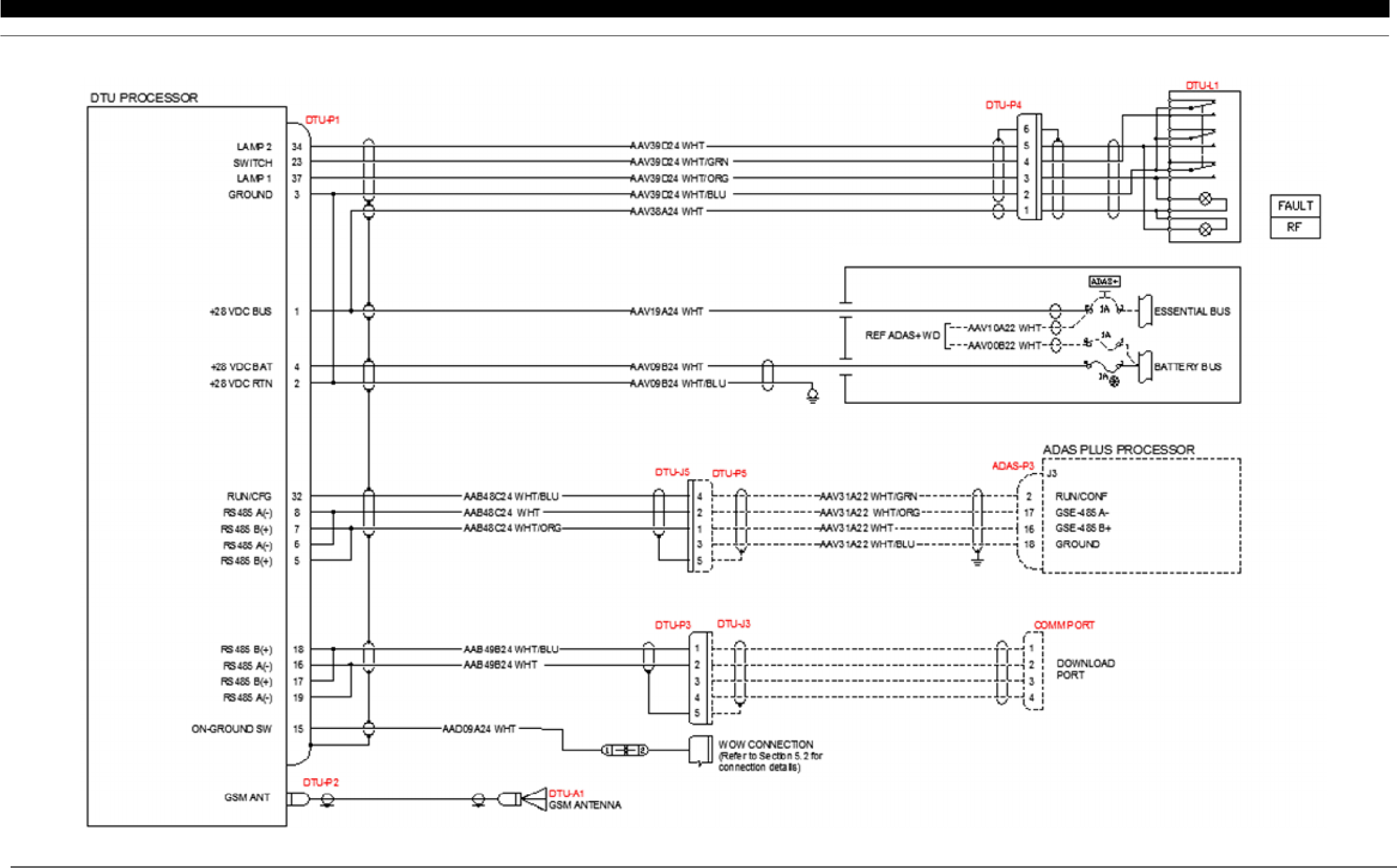
DTU-G-010-1/B, Rev L, June 09, 2015 34 of 37
6.2 DTU / ADAS+ Interconnect Schematic (Except Cessna Caravan)
Figure B- 20: DTU / ADAS+ Wiring Schematic (Except Cessna Caravan)
P&W ENGINE SERVICES, INC. Data Transmission Unit DTU-G-010-1/B
Part 23 Aircraft Generation III Monitors
This Document is Subject to the Restrictions Contained on Cover Page
The export control classification with respect to this document is contained on the first page
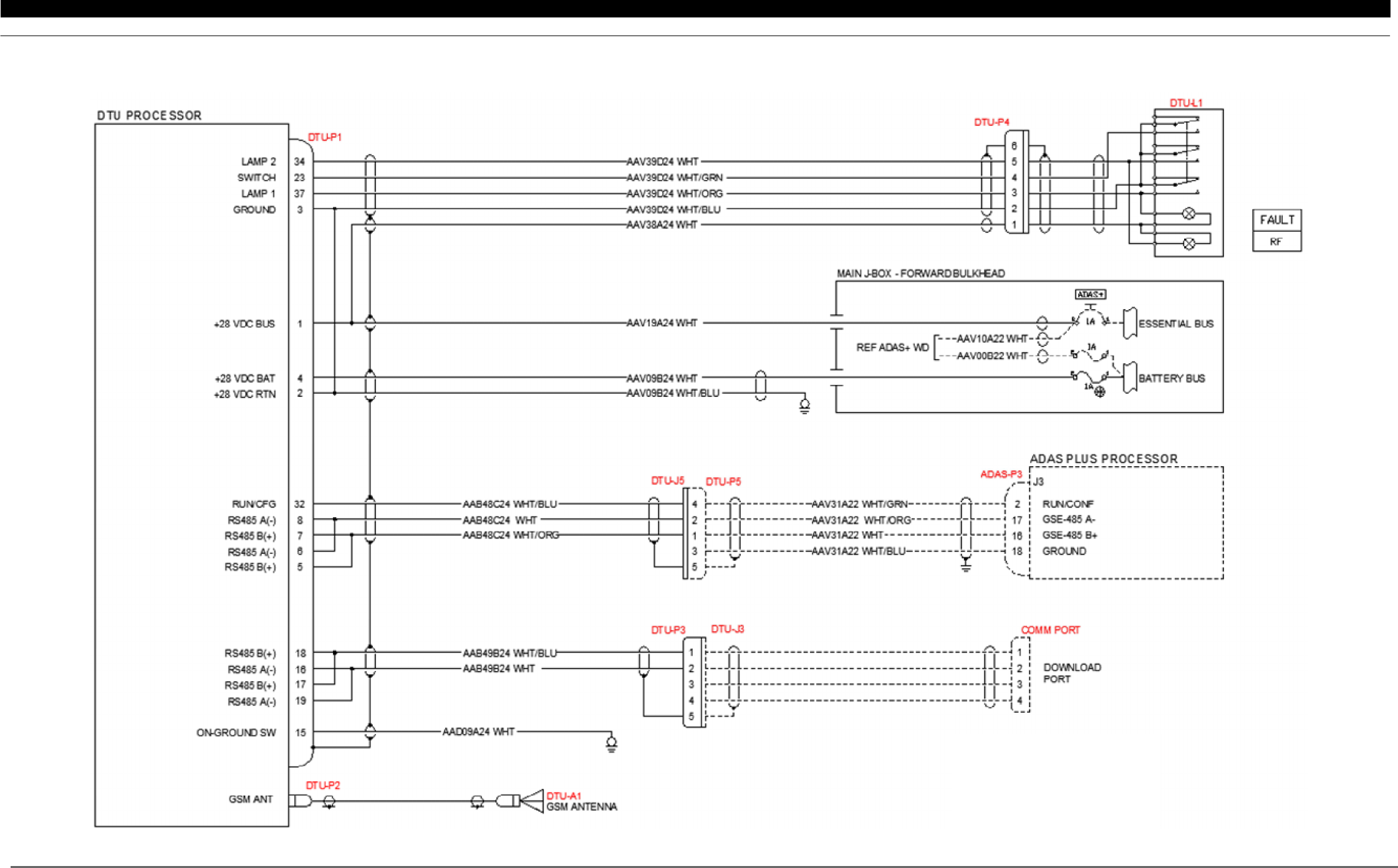
DTU-G-010-1/B, Rev L, June 09, 2015 35 of 37
6.3 DTU / ADAS+ Interconnect Schematic (Cessna Caravan STC Installation)
Figure B- 21: DTU / ADAS+ Wiring Schematic (Cessna Caravan STC Installation)
P&W ENGINE SERVICES, INC. Data Transmission Unit DTU-G-010-1/B
Part 23 Aircraft Generation III Monitors
This Document is Subject to the Restrictions Contained on Cover Page
The export control classification with respect to this document is contained on the first page
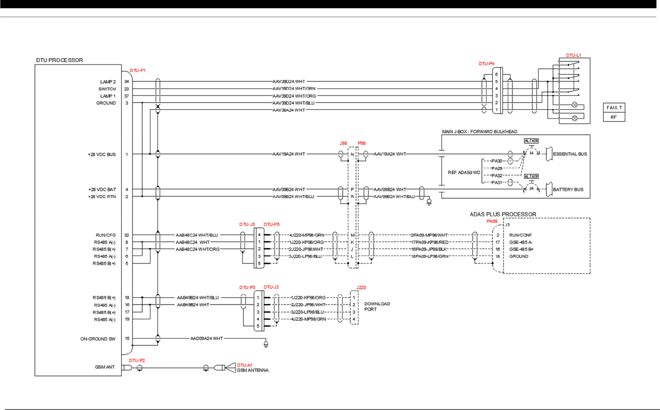
DTU-G-010-1/B, Rev L, June 09, 2015 36 of 37
6.4 DTU / ADAS+ Interconnect Schematic (Cessna Caravan Factory Installation)
Figure B- 22: DTU / ADAS+ Wiring Schematic (Cessna Caravan Factory Installation)
P&W ENGINE SERVICES, INC. Data Transmission Unit DTU-G-010-1/B
Part 23 Aircraft Generation III Monitors
This Document is Subject to the Restrictions Contained on Cover Page
The export control classification with respect to this document is contained on the first page
DTU-G-010-1/B, Rev L, June 09, 2015 37 of 37
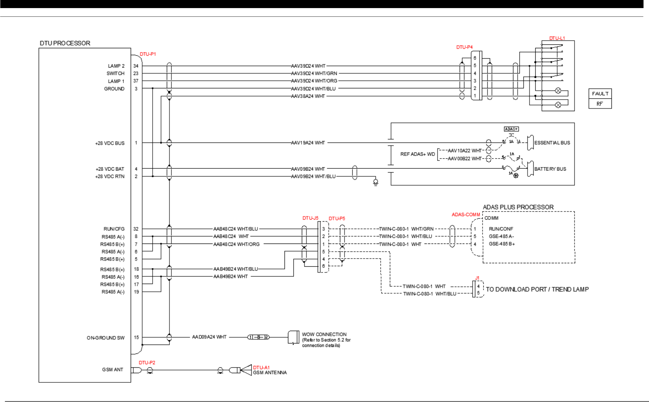
6.5 DTU / ADAS+ Upgrade Interconnect Schematic
Figure B- 23: DTU / ADAS+ Upgrade Wiring Schematic