Precise Biometrics MS010120 Fingerprint Reader User Manual Installation
Precise Biometrics AB Fingerprint Reader Users Manual Installation
Contents
- 1. Users Manual Installation
- 2. Users Manual
Users Manual Installation
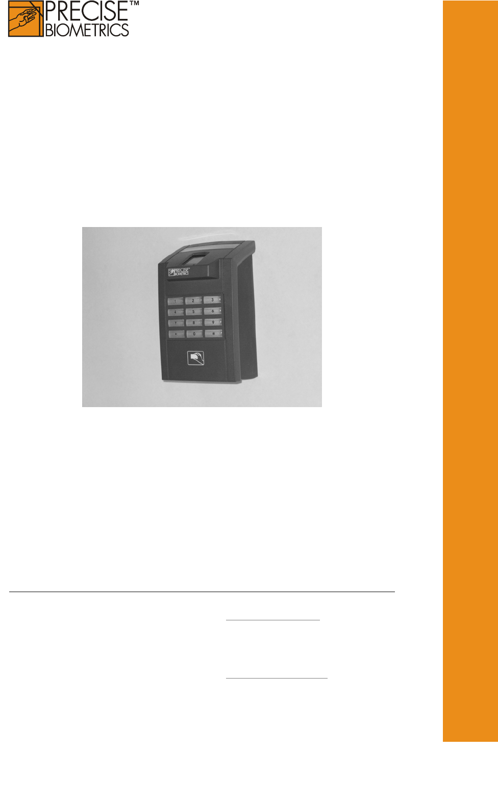
Installation of
Precise BioAccess™ 200
Sweden Precise Biometrics AB, Scheelevägen 19 C, SE-223 70 Lund
Phone +46 46 31 11 00 Fax +46 46 31 11 01 info@precisebiometrics.com
Precise Biometrics AB, Finlandsgatan 66 2nd floor, SE-164 74 Kista
Phone +46 8 632 33 50 Fax +46 8 632 33 55 info@precisebiometrics.com
USA Precise Biometrics Inc, 8300 Boone Boulevard, Suite 500, Vienna VA 22182
Phone +1 (703) 848 9266 Fax +1 (703) 832 0577 infous@precisebiometrics.com
UK Precise Biometrics Ltd, 288 Bishopsgate, London EC2M 4QP
Phone +44 (0) 207 959 3060 Fax +44 (0) 207 959 3030 info@precisebiometrics.com
www.precisebiometrics.com
1.
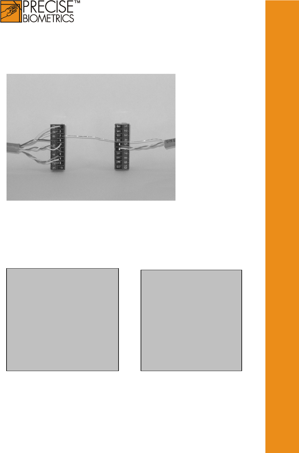
Connect the wires using a shielded cable. The shielding must be
connected to earth at the access control side of the system.
BioAccess plint 1
1 Do not connect
2 DATA (magstripe) / DATA 0
(Wiegand) OUTPUT
3 CLOCK (magstripe) / DATA 1
(Wiegand) OUTPUT
4 CARD PRESENT OUTPUT
5 RS485 B
6 RS485 A
7 ground
8 Extra ground
9 Extra ground
10 POWER 12-24 VDC
BioAccess plint 2
1 Do not connect
2 Do not connect
3 Do not connect
4 Do not connect
5 RS232 Out
6 RS232 In
7 Do not connect
8 Do not connect
9 Do not connect
10 Do not connect
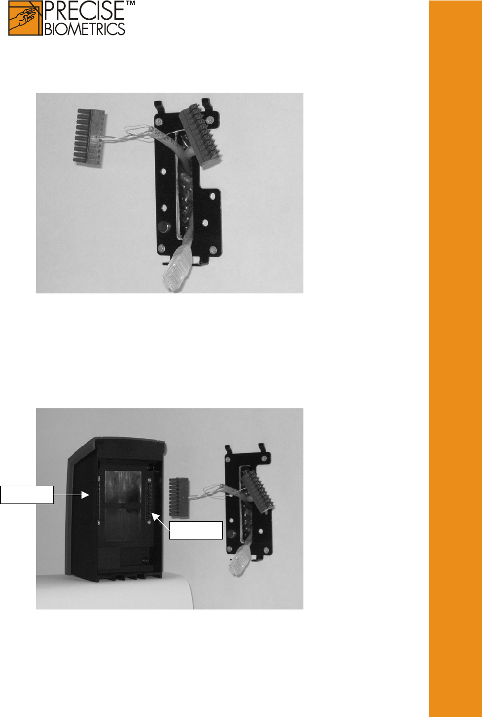
2.
Fasten the holder onto the wall. Recommended mounting
height 1.4meter/4.6 feet.
3.
Plug the connector(s). Plint 1 should be connected to the left
and plint 2 should be connected to the right.
Plin
t
1
Plin
t
2
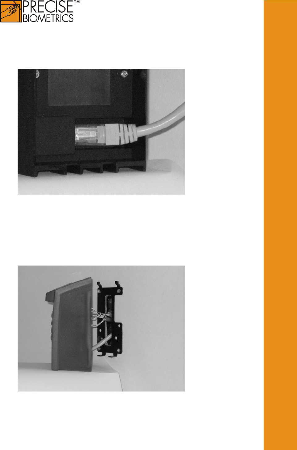
4.
If the BioAccess reader is going to be connected to an
Ethernet, connect the RJ-45 contact.
5.
Mount Precise BioAccess™ 200 onto the holder.
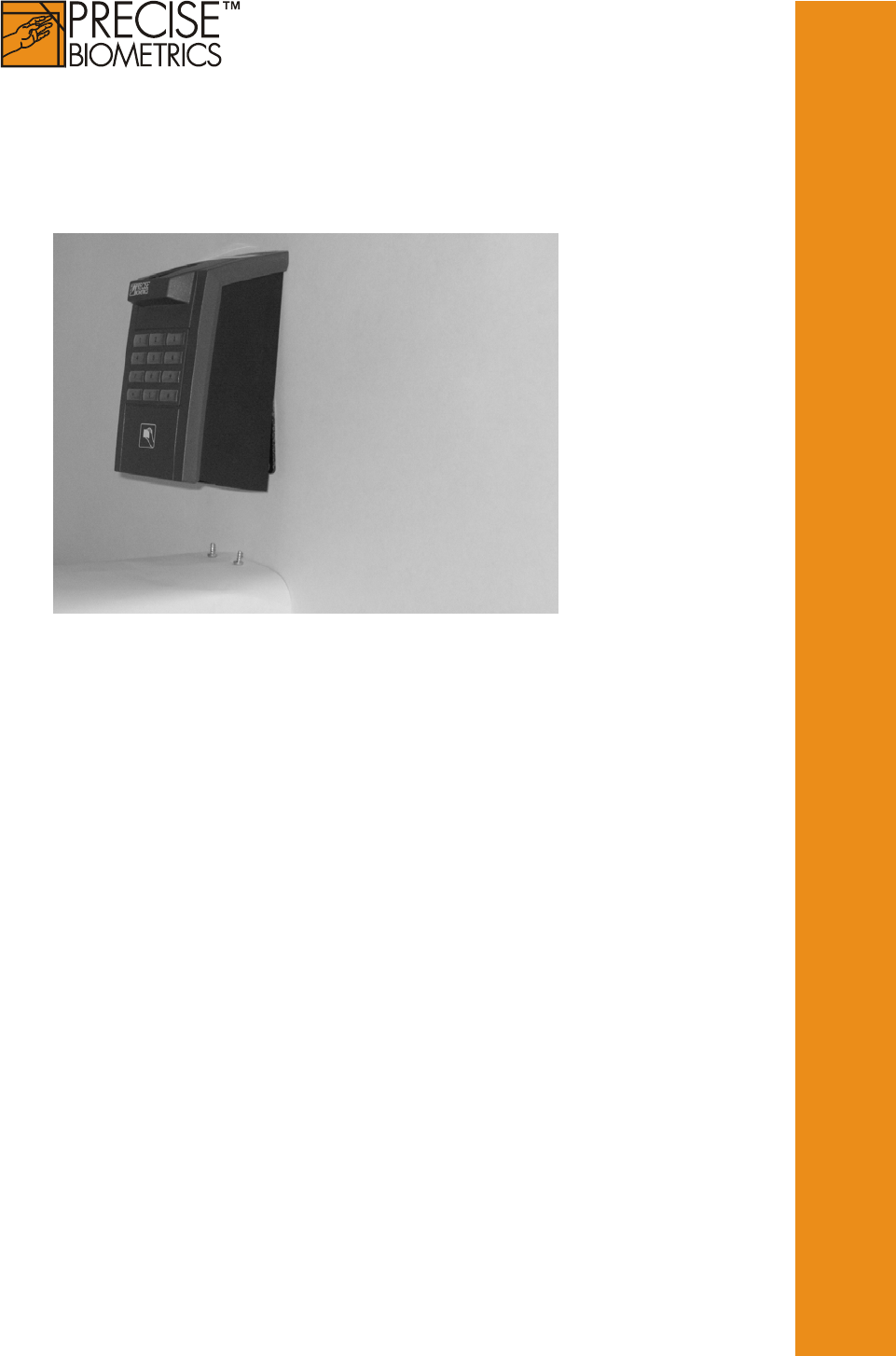
6.
Secure Precise BioAccess™ 200. Use only screw driver Torx
T10. Torque max 1.0 Nm.

CE Notice (Europe)
This device meets the following technical standards as indicated by the
symbol on the device:
• EN 55022:1998 Limit B (Radiated emission)
• EN 55024:1998 (Immunity of IT-equipment)
• EN 61000-6-2:1999 (Immunity for industrial environments)
• EN 300 330-2: v.1.1.1 (06-2001) (Radio - spectrum)
• EN 301 489-01: v.1.2.1 (07-2000) (Radio - EMC)
• EN 301 489-03 (07-2000) (Radio - EMC)
FCC Information (USA)
This device has been certified to the FCC rules and regulations (CFR47
Part 15 Subpart C) for the low power transmitter contained within this
device. In addition, this device has also been verified to comply with Class
B digital device requirements as specified in the FCC rules and
regulations (CFR47 Part 15 Subpart B).
This device complies with Part 15 of the FCC Rules. Operation is subject to
the following two conditions: (1) this device may not cause harmful
interference, and (2) this device must accept any interference received,
including interference that may cause undesired operation.
NOTE: This equipment has been tested and found to comply with the
limits for a Class B digital device, pursuant to Part 15 of the FCC Rules.
These limits are designed to provide reasonable protection against harmful
interference in a residential installation. This equipment generates, uses
and can radiate radio frequency energy and, if not installed and used in
accordance with the instructions, may cause harmful interference to radio
communications. However, there is no guarantee that interference will not
occur in a particular installation. If this equipment does cause harmful
interference to radio or television reception, which can be determined by
turning the equipment off and on, the user is encouraged to try to correct
the interference by one or more of the following measures:
• Reorient or relocate the receiving antenna.
• Increase the separation between the equipment and receiver
is connected
• Connect the equipment into an outlet on a circuit different from that to
which the receiver
• Consult the dealer or an experienced radio/TV technician for help
CAUTION: Changes or modifications not expressly approved by the party