Precision Enterprise ACL300 Wireless Rear View Backup System User Manual ADS043 manualx
Precision Enterprise Ltd Wireless Rear View Backup System ADS043 manualx
User Manual
WIRELESS BACK-UP CAMERA SYSTEM
with 12cm / 4.3” monitor
PKC0BU4 Tx
2
INTRODUCTION
The Pro-User PKC0BU4 Tx is member of the family of advanced car back-up
systems manufactured by Pro User International Ltd.
The Pro-User Digital Back-up Camera and Monitor with built in transmitter box, when
used as described, will improve your ability to see behind your car, camper, trailer, or
mini-van. We have taken numerous measures in quality control to ensure that your
product arrives in top condition, and will perform to your satisfaction.
Please carefully read and follow the following safety and operating instructions.
IMPORTANT SAFETY INSTRUCTIONS
Before You Install
If you are not confident working with 12/24 volt DC vehicle wiring, removing and
reinstalling interior panels, carpeting, dashboards or other components of your vehicle,
contact the vehicle’s manufacturer, or consider having the camera system professionally
installed.
Interference
This device, free from the interference comes from blue tooth, cell phones, Wi-FI routers,
power lines and other various electrical equipment, etc.
Repair
The camera system should not be opened. Any attempt at modification or repair by the
user will entail the loss of your guarantee.
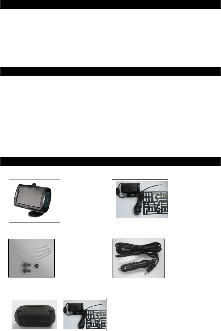
PARTS
1. Monitor and mounting Arm 2. Camera with mounting plate
3. Mounting Accessories 4. Monitor Power Cable
5. magnetic loop for camera cable
3
INSTALLATION
These instructions do not apply to all vehicles. They are only meant as a general
guide due to the number of different makes & models. For vehicle specific
questions contact your vehicle’s manufacturer.
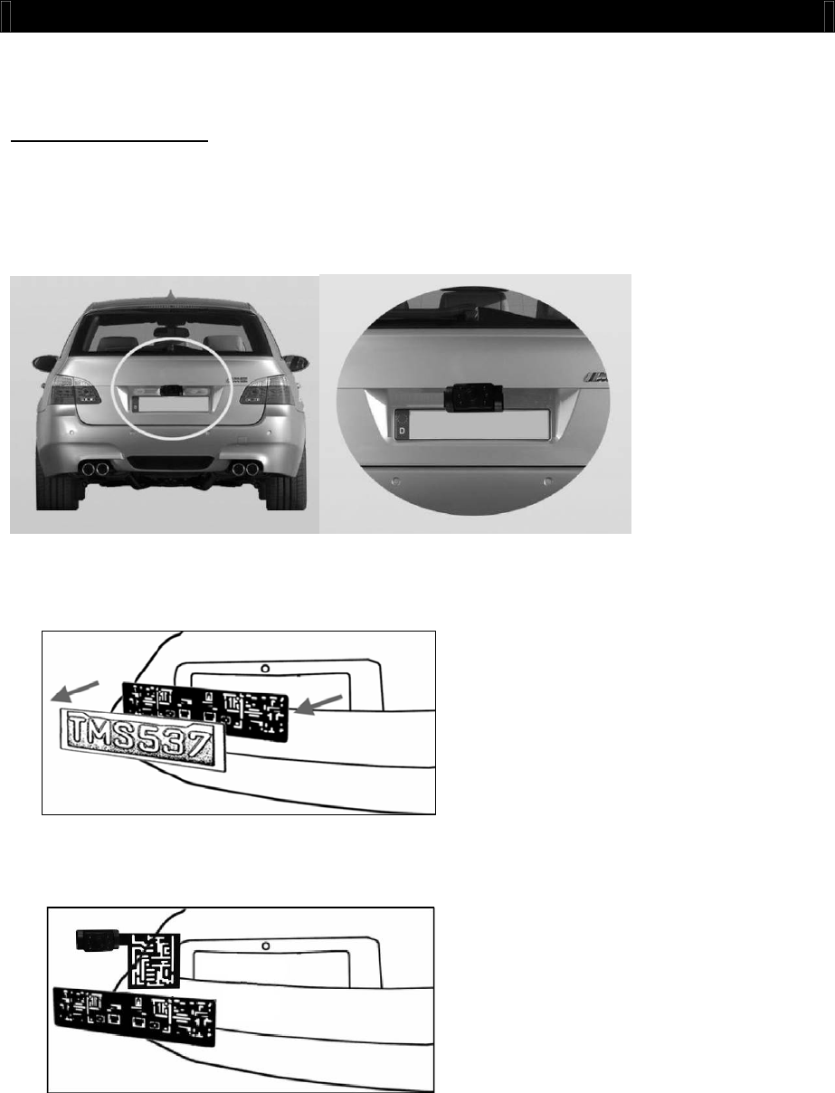
Camera installation
There are several ways to mount the camera on the back of your car. But the most
convenient is to mount it near the license plate of the car. Supplied is one mounting plate
that can be fixed behind the license plate, and the mounting plate have been installed in
the camera.
The camera is tiltable, camera angle can be adjusted manually on vertical direction.Make
sure that its field of view and detection are not obstructed.
At some type of cars it is not possible to mount the camera near the license plate. You
may have to find another spot at the back of your car to mount the camera.
1. Remove the rear license plate, and then loosen the license plate bolts/screws.
2. Position the supplied mounting plates (with camera together) behind the license plate
bracket. Secure both license plate bracket and mounting plates with the license plate
bracket bolts/screws.
4
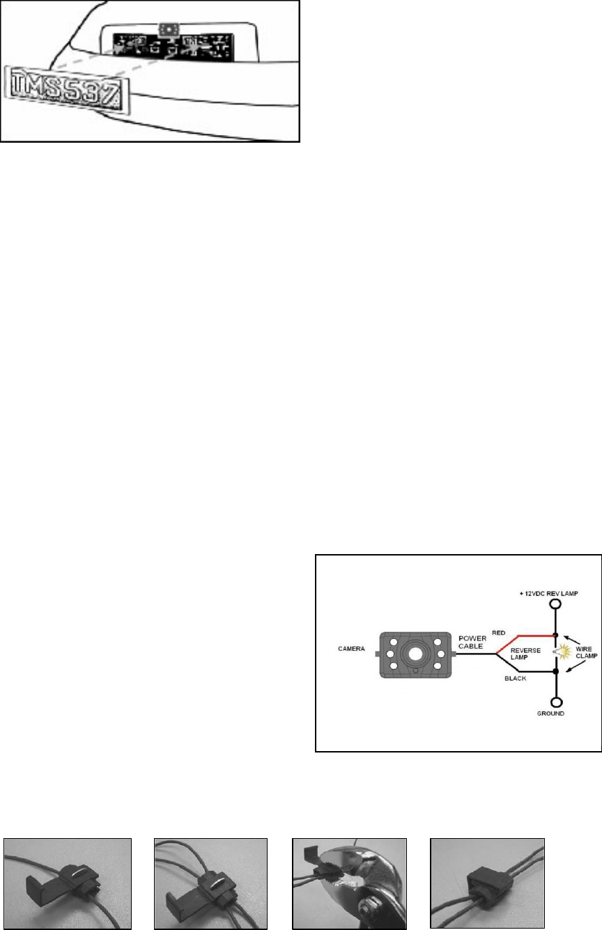
3. Mount the license plate on the license plate bracket.
4. Choose a routing path for the camera’s power cable through the vehicle’s body to the
reverse light circuit. If in doubt, seek professional installation assistance.
5. Some vehicles may have a hole available to pass the wire through, such as where the
license plate light is mounted, or you can drill a hole close to where the power cable
is attached to the camera. Once you have chosen where the cable will enter the
vehicle’s body, remove the camera. If you are able to use an existing opening, skip
the next two steps.
6. Before you drill a hole you MUST CHECK and see WHAT IS BEHIND WHERE YOU ARE
DRILLING. If there are any vehicle components, such as electrical parts or fuel
system components behind where you are drilling, you must take whatever
precaution is necessary not to damage them. Remove the license plate and camera
before drilling.
7. After you have drilled the hole, insert the supplied grommet, then pass the camera
cables through the grommet into the vehicle. You must use the grommet to prevent
the metal edge of the hole from cutting the camera cable.
8. Next you’ll need to find the vehicle’s reverse lights. Turn the vehicle’s ignition key to
the accessory position, engage the parking brake and put the car in reverse. Look at
the vehicle’s tail lights to see where the reverse lights are located, they are the white
lights. To locate the reverse light’s 12 / 24 V+ wire it will be necessary to gain access
to the rear of the vehicle’s tail light. For help locating the vehicle’s reverse light circuit
contact your vehicle’s manufacturer for vehicle specific wiring diagrams.
9. Once you have located the reverse light circuit you will have to route the camera
cable to that location. You must securely fasten the power cable to prevent it from
being caught on any vehicle component such as the trunk hinge. Never route the
cable on the outside of the vehicle!
10. The reverse light sockets on most vehicles
have two wires connected to them.
Usually the negative wire is black and the
positive wire is a colored wire. If you are
uncertain about the wiring, you can use a
12 / 24 volt multimeter available at most
auto parts stores to determine which is
the positive wire. Follow the
manufacturer’s instructions for the safe
use of the multimeter.
11. After determining which wire is the
positive and which is the negative, turn
off the ignition key, then remove the battery’s negative cable.
12. Splice the red wire using the supplied in-line wire connectors to the reverse light’s
positive (+) wire. Use a set of slip joint pliers to squeeze the TAP and insure good
connection.
5
13. Next splice the black wire of the camera power cable to the reverse light’s negative (-)
wire or ground.
14. Replace the reverse light bulb, and then re-install the light socket. Secure all the
wires with cable ties or electrical tape.
15. Re-attach the negative battery cable to the battery.
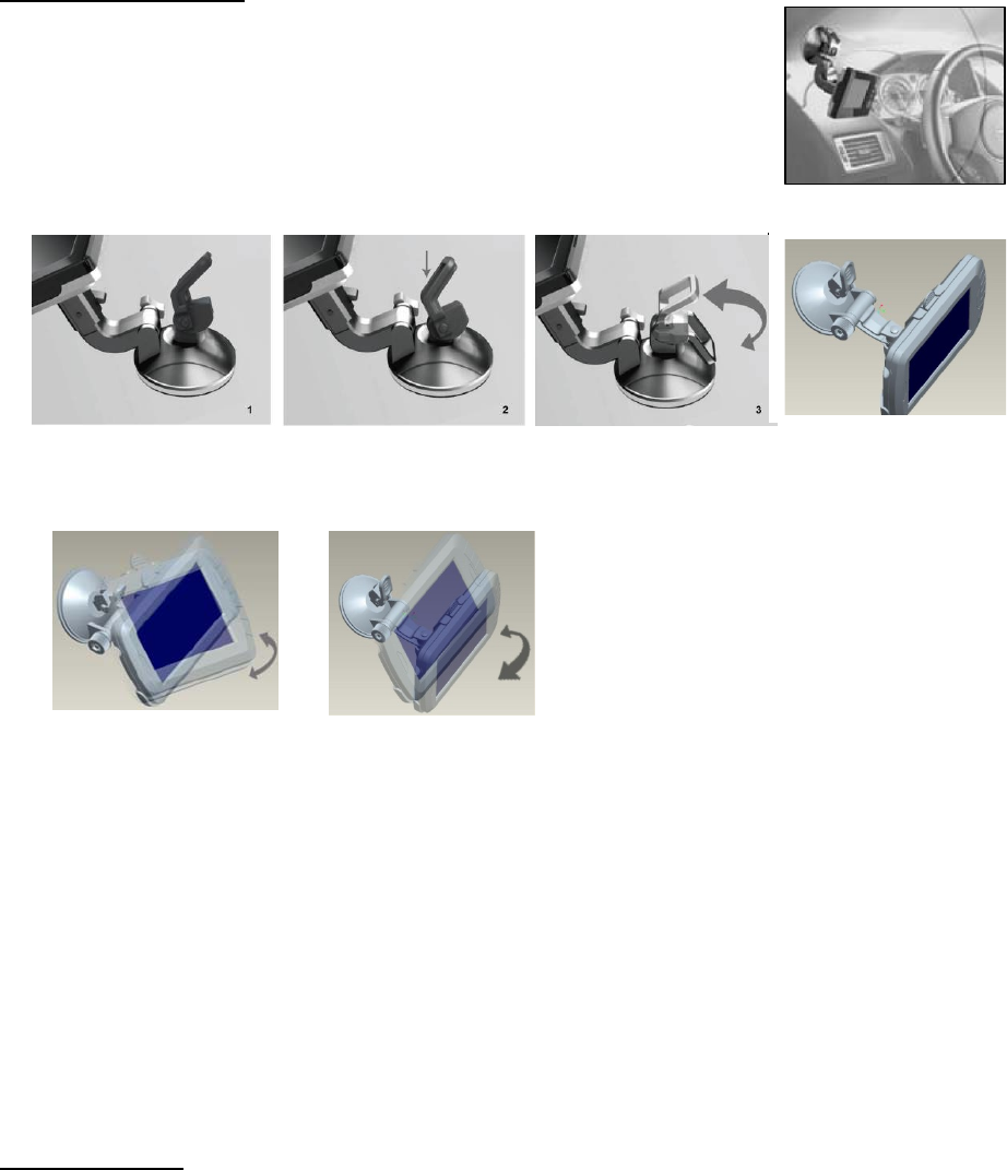
Monitor Installation
When choosing a location to mount the monitor, make sure the
monitor is in an area that will not obstruct your vision while driving.
1. Before mounting the monitor, clean the mounting surface well.
2. Position the suction mount to the smooth surface which suits
your requirement.
3. Press the suction cap against the smooth surface and press the
lock down to attach and fix the mount to the surface.
Snap in the monitor to the suction mount.
4. Adjust the mounting arms to suit your view angle to the monitor and tighten the
screws on the mount to fix the position.
5. Route the power cable to the vehicle’s cigarette lighter socket/12/24V power outlet.
The cable must not interfere with the safe operation of the vehicle.
6. Insert the small 12 / 24Volt DC plug of the power cable into the right side of the
monitor.
7. Plug the 12 / 24 Volt cigarette lighter plug into the vehicle’s cigarette lighter socket.
To maximize the effectiveness of the suction mount, it is recommended that the
application be performed under the following conditions:
•Surface temperature should be between 21 and 38 degrees Celsius.
•Application below 10 degrees should be avoided.
•Application should not occur in direct sunlight.
Mounting should be protected from exposure to direct sunlight for a period of 24 hours.
NOTE: UNDER EXTREME BRIGHT LIGHT CONDITIONS, THE SCREEN IMAGE MAY TAKE A
FEW SECONDS TO STABLIZE. PLEASE WAIT UNTIL THE IMAGE HAS STABLIZED BEFORE
BACKING UP.
System testing
1. Reattach the vehicle’s negative battery cable.
2. Turn the ignition key to the accessory position, do not start the vehicle.
3. Engage the parking brake, and then put the shifter in the reverse position.
4. After testing the unit and you are satisfied with the route you have chosen for the
cabling, you must permanently install it.
5. Route all wires behind interior panels or under carpeting so they are hidden. Use
supplied cable ties to neatly gather any excess wire.
6
OPERATION
Please always pair the monitor and camera during the 1st operation, operation details
please refer below step.
The monitor will automatically turn on when the vehicle is in reverse gear.
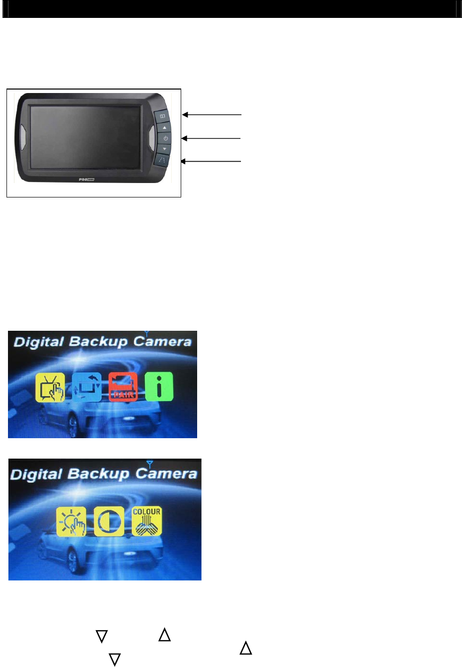
There are 5 control buttons available for users to have their controls:
Power button
Press the POWER button to supply power to the monitor. When the monitor image is on,
the blue LED will be lit. If there is power to the monitor, but the monitor image is OFF,
the blue LED will blink on and off. When the monitor power is off, no picture can appear
on the screen and the blue LED will be off.
Menu button
Press the Menu button to enter the menu screen as shown below: Picture SPEC, Picture
Direction, Pair, Product Information.
Repeat pressing the Menu button to enter into “Picture SPEC” then select Brightness,
contrast or colourof the picture.
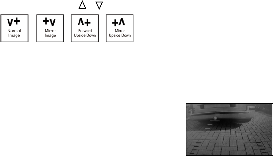
Always press the button or button to select the proper function icons and adjust
settings within the control selected. Press the button to select last icon / increase the
value and press the button to select next icon / decrease the value.
Menu button
Guideline button
Power button
7
To change the orientation of the screen image, press the menu button until direction is
selected. By pressing the or button repeatedly, different screen orientations will be
available. These different views allow you to
mount the camera and monitor in any
position with keeping the right picture on the
monitor.
To exit the screen, press the menue button or it will automatically exit after 10s.
Press the “Pair” icon to pair the monitor and camera if it’s the 1st operation, then press
the rubber button on the bottom of camera until the signal well received by the monitor,
an “OK” will be appeared on the screen then the unit would work properly and will
automatically pair by itself in the future operation. Press menue button to exist the
selection or it will automatically exit after 30s.
Guideline button
This camera system has the option to show distance-
guidelines on the display. This helps you to visually see
the distance between the objects behind your car. By
pressing the guideline button, you can switch this option
on and off.
Note : Cet appareil est conforme à la Partie 15 des règlements de la FCC et aux normes
RSS de l’Industrie du Canada. Son fonctionnement est soumis aux deux conditions
suivantes : (1) cet appareil ne doit pas causer des interférences nuisibles, et (2) cet
appareil doit accepter toute interférence reçue, y compris les interférences qui peuvent
provoquer un fonctionnement indésirable.
Le fabricant n'est pas responsable des toutes interférences radio ou télévision causées par
des modifications non autorisées apportées à cet appareil. De telles modifications peuvent
empêcher l’utilisateur d’utiliser l'appareil.
THIS DEVICE COMPLIES WITH PART 15 OF THE FCC RULES AND INDUSTRY CANADA
LICENSE-EXEMPT RSS STANDARD(S). OPERATION IS SUBJECT TO THE FOLLOWING
TWO CONDITIONS: (1) THIS DEVICE MAY NOT CAUSE HARMFUL INTERFERENCE,
AND (2) THIS DEVICE MUST ACCEPT ANY INTERFERENCE RECEIVED, INCLUDING
INTERFERENCE THAT MAY CAUSE UNDESIRED OPERATION.
THE MANUFACTURER IS NOT RESPONSIBLE FOR ANY RADIO OR TV INTERFERENCE
CAUSED BY UNAUTHORIZED MODIFICATIONS OR CHANGE TO THIS EQUIPMENT.
SUCH MODIFICATIONS OR CHANGE COULD VOID THE USER’S AUTHORITY TO
OPERATE THE EQUIPMENT.
This radio transmitter (identify the device by certification number or model number if
Category II) has been approved by Industry Canada to operate with the antenna types
listed below with the maximum permissible gain indicated. Antenna types not included in
this list, having a gain greater than the maximum gain indicated for that type, are strictly
prohibited for use with this device.
Le présent émetteur radio (identifier le dispositif par son numéro de certification ou son
numéro de modèle s'il fait partie du matériel de catégorie II) a été approuvé par Industrie
Canada pour fonctionner avec les types d'antenne énumérés ci dessous et ayant un gain
admissible maximal. Les types d'antenne non inclus dans cette liste, et dont le gain est
supérieur au gain maximal indiqué, sont strictement interdits pour l'exploitation de l'émetteur.
Antenna Type : internal permanent antenna
Max. Antenna Gain:0dBi
To maintain compliance with FCC’s RF exposure guidelines, this equipment should be installed
and operated with a minimum distance of 20cm between the radiator and your body.