Precision Enterprise ARF370 Wireless Rear View Backup System User Manual PKC0BU7 BackUp Camera indd
Precision Enterprise Ltd Wireless Rear View Backup System PKC0BU7 BackUp Camera indd
UserManual.wiki
>
Precision Enterprise
>
ARF370 User Manual
User Manual
Navigation menu
Upload a User Manual
Namespaces
Wiki Guide
HTML
PDF
Info
Views
User Manual
Discussion / Help
Navigation

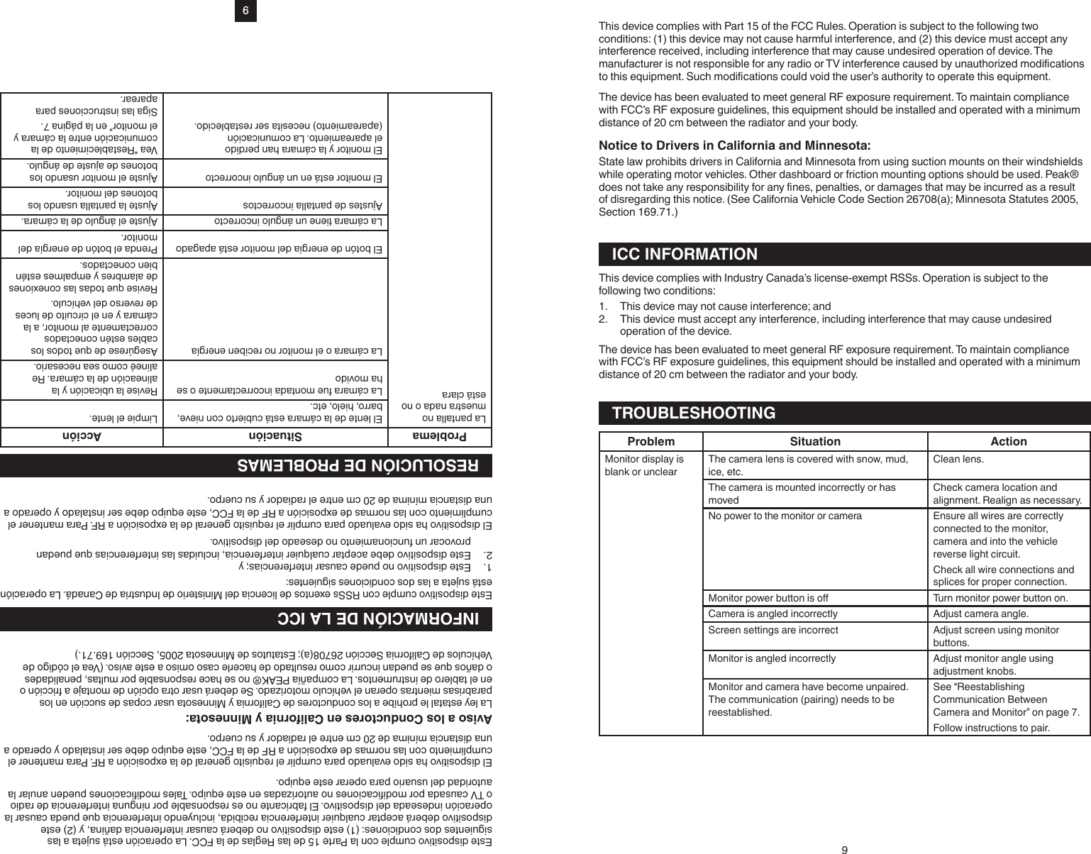
![81. Select set up .2. Select version .CARE AND MAINTENANCEStorageStore this Back-Up Camera in a cool, dry area and keep it away from direct sunlight, heat, excessive humidity and dampness.CleaningDo not clean or wipe the Back-Up Camera with solvents or chemical materials. If necessary, remove dirt or stains using a soft cloth dampened with a mild detergent solution.Fuse Replacement1. Turn the cap on the tip of the power plug counterclockwise (no tools needed).2. Remove the cap, center pin and fuse.3. Replace the fuse with a new 1-amp fuse.4. Replace the center pin and cap. Turn the cap clockwise.DisposalThe Back-Up Camera is designed to provide years of service. The Back-Up Camera should be recycled or safely disposed of at a local electronics recycler. Examples of places metal dealers.SPECIFICATIONSCameraCurrent consumption (with transmitter) <250 mAPixels 640 x 480View angle (measured 9.8 ft [3 m] from camera) 110°Frequency 2400-2483.5 ± 0.3 MHzRF transmission distance no interference: ≥ 492 ft (150 m)Operation/storage temperature 14° to 140°F (-10° to 60°C)MonitorLCD display screen size 7.0 in. (178 mm)Power cord fuse 1AFCC INFORMATION Changes or modications to this equipment not expressly approved by the party responsible for compliance could void the user’s authority to operate the equipment. This equipment has been tested and found to comply with the limits for a Class B digital device, pursuant to Part 15 of the FCC Rules. These limits are designed to provide reasonable protection against harmful interference in a residential installation. This equipment can radiate radio frequency energy and, if not installed and used in accordance with the instructions, may cause harmful interference to radio communications. However, there is no guarantee that interference will not occur in a particular installation. If this equipment does cause harmful interference to radio or television reception, which can be determined by turning the equipment o and on, the user is encouraged to try to correct the interference by one or more of the following measures:• Reorient or relocate the transmitter.• Increase the separation between the equipment and monitor.• Connect the equipment into an outlet on a circuit dierent from that to which the monitor is needed.• Consult the dealer or an experienced radio/TV technician for help.8Para ver el rmware:1. Seleccione conguración .2. Seleccione la versión .CUIDADOS Y MANTENIMIENTOAlmacenajeAlmacene esta Cámara de Retroceso en una área fría y seca, alejada de la luz solar directa, el calor y la humedad excesiva.LimpiezaNo limpie o le pase un trapo impregnado con disolventes o materiales químicos a la Cámara de Retroceso. Si es necesario, remueva la mugre o las manchas con un trapo suave humedecido en una solución de detergente suave.Reemplazo del Fusible1. Gire la tapa de la punta del enchufe de energía en el sentido contra horario (no se necesitan herramientas).2. Remueva la tapa, el pasador central y el fusible.3. Reemplace el fusible por uno de 1 amperios.4. Reinstale el pasador central y la tapa. Gire la tapa en el sentido horario.DescarteLa Cámara de Retroceso fue diseñada para proporcionarle años de servicio. La Cámara de Retroceso debe ser reciclada o desechada de forma segura en una empresa local de reciclaje de electrónicos. Ejemplos de lugares que aceptan artículos como este son: centros de entrega de artículos para reciclado municipales o del condado como también distribuidores de chatarra.ESPECIFICACIONESCámaraConsumo de corriente (con transmisor) <250 mAPixeles 640 x 480Ángulo de visualización (medido 9.8 pies [3 m]) desde la cámara)110°Frecuencia 2400-2483,5 ± 0,3 MHz.Distancia de transmisión RF sin interferencias: ≥ 492 pies (150 m)Temperatura de almacenaje/operación 14° a 140 °F (-10° a 60 °C)MonitorTamaño de la pantalla LCD 7,0 pul. (178 mm)Fusible del cable de energía 1AINFORMACIÓN DE LA FCCADVERTENCIACambios o modicaciones a este equipo no aprobadas expresamente por la parte responsable de cumplimiento podrá anular la autoridad del usuario para operar el equipo.AVISO Este equipo ha sido probado y se encontró que cumple con los límites de un dispositivo digital Clase B, conforme a la Parte 15 de las Reglas de la FCC. Estos límites fueron diseñados para suministrar protección razonable contra interferencias dañinas en una instalación residencial. Este equipo puede emitir frecuencia radial y energía y, si no se instala y se usa de acuerdo con las instrucciones, podrá causar interferencia dañina para las comunicaciones radiales. Sin embargo, no hay garantía de que dicha interferencia no ocurra en una instalación en particular. Si este equipo causa interferencia dañina a la recepción de radio o televisión, lo cual puede ser determinado apagando y encendiendo el equipo, alentamos al usuario para que trate de corregir la interferencia por medio de una o más de las siguientes medidas:• Reoriente o reubique el transmisor.• Aumente la separación entre el equipo y el monitor.• Conecte el equipo en una toma de corriente de un circuito diferente a donde se necesita el monitor.• Consulte al agente o a un técnico de radio/TV para obtener ayuda.](https://usermanual.wiki/Precision-Enterprise/ARF370/User-Guide-3161187-Page-8.png)