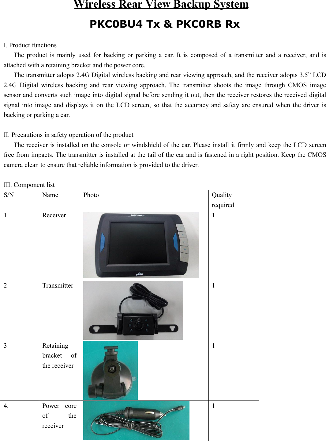
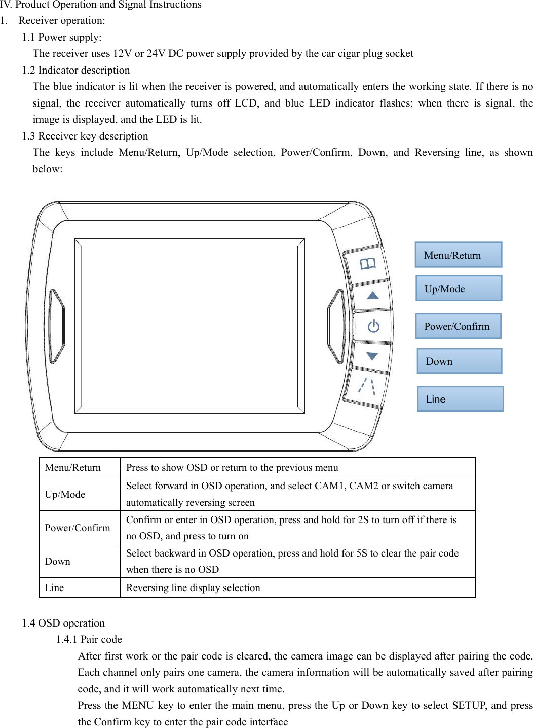
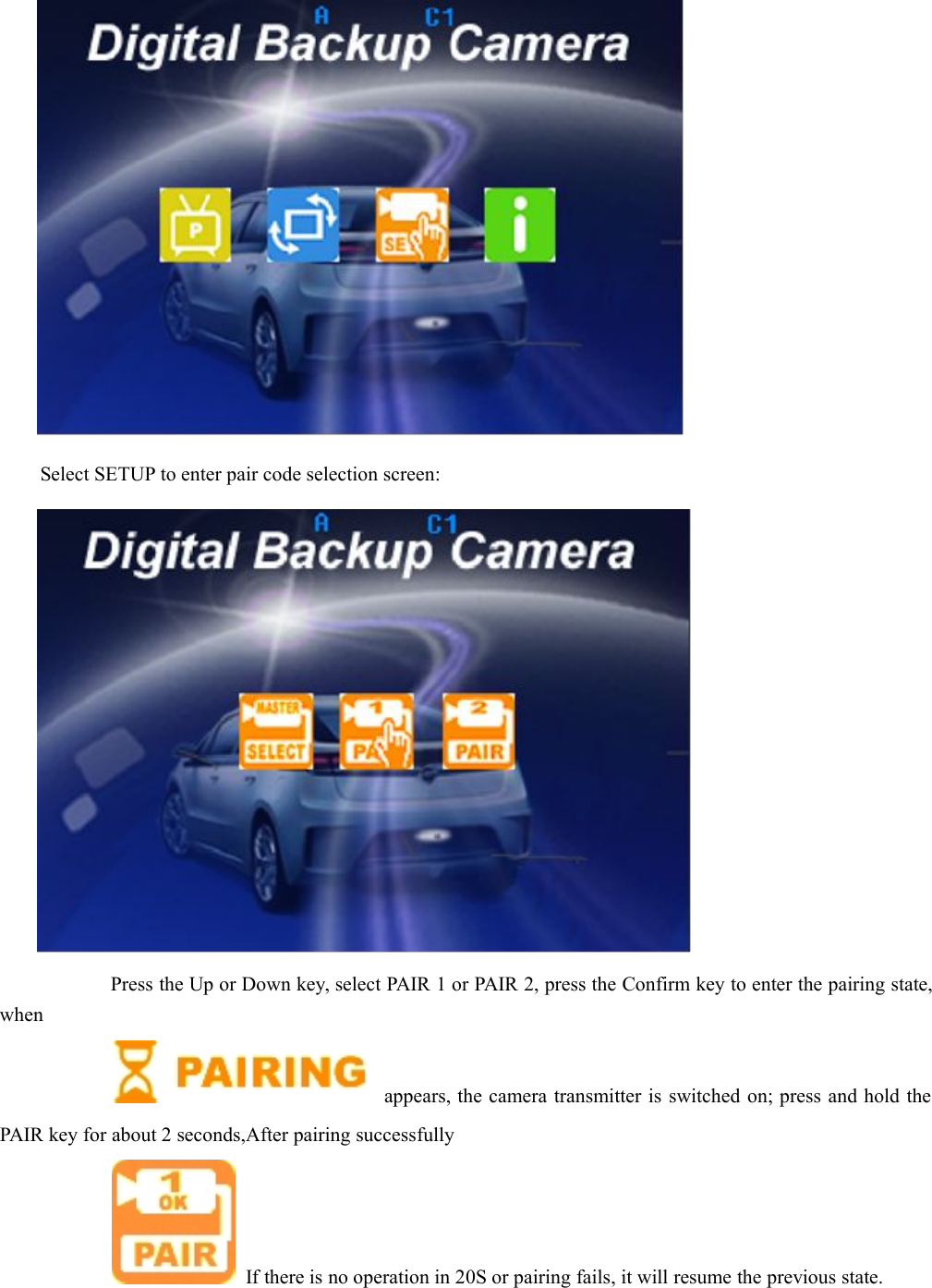
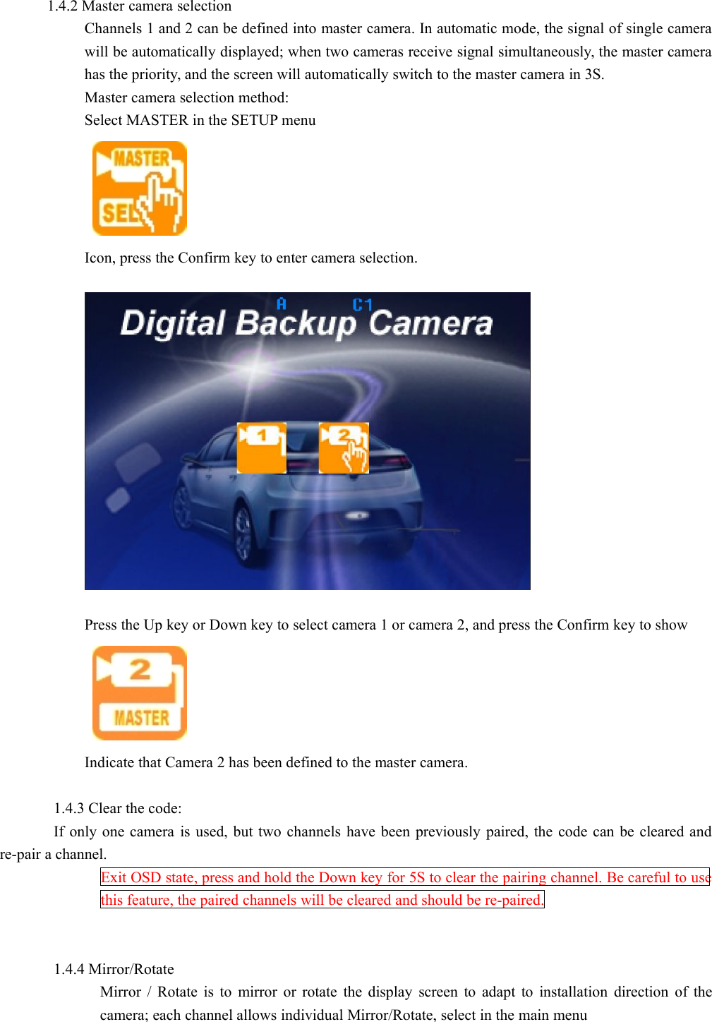
Precision Enterprise ARH335 Wireless Rear View Backup System User Manual

Precision Enterprise Ltd Wireless Rear View Backup System Users Manual

User Manual

Wireless Rear View Backup SystemI. Product functionsThe product is mainly used for backing or parking a car. It is composed of a transmitter and a receiver, and isattached with a retaining bracket and the power core.The transmitter adopts 2.4G Digital wireless backing and rear viewing approach, and the receiver adopts 3.5” LCD2.4G Digital wireless backing and rear viewing approach. The transmitter shoots the image through CMOS imagesensor and converts such image into digital signal before sending it out, then the receiver restores the received digitalsignal into image and displays it on the LCD screen, so that the accuracy and safety are ensured when the driver isbacking or parking a car.II. Precautions in safety operation of the productThe receiver is installed on the console or windshield of the car. Please install it firmly and keep the LCD screenfree from impacts. The transmitter is installed at the tail of the car and is fastened in a right position. Keep the CMOScamera clean to ensure that reliable information is provided to the driver.III. Component listS/NNamePhotoQualityrequired1Receiver12Transmitter13Retainingbracket ofthe receiver14.Power coreof thereceiver1 PKC0BU4 Tx & PKC0RB Rx
IV. Product Operation and Signal Instructions1. Receiver operation:1.1 Power supply:The receiver uses 12V or 24V DC power supply provided by the car cigar plug socket1.2 Indicator descriptionThe blue indicator is lit when the receiver is powered, and automatically enters the working state. If there is nosignal, the receiver automatically turns off LCD, and blue LED indicator flashes; when there is signal, theimage is displayed, and the LED is lit.1.3 Receiver key descriptionThe keys include Menu/Return, Up/Mode selection, Power/Confirm, Down, and Reversing line, as shownbelow:Menu/ReturnPress to show OSD or return to the previous menuUp/ModeSelect forward in OSD operation, and select CAM1, CAM2 or switch cameraautomatically reversing screenPower/ConfirmConfirm or enter in OSD operation, press and hold for 2S to turn off if there isno OSD, and press to turn onDownSelect backward in OSD operation, press and hold for 5S to clear the pair codewhen there is no OSDLineReversing line display selection1.4 OSD operation1.4.1 Pair codeAfter first work or the pair code is cleared, the camera image can be displayed after pairing the code.Each channel only pairs one camera, the camera information will be automatically saved after pairingcode, and it will work automatically next time.Press the MENU key to enter the main menu, press the Up or Down key to select SETUP, and pressthe Confirm key to enter the pair code interfaceMenu/ReturnUp/ModePower/ConfirmDownLine
Select SETUP to enter pair code selection screen:Press the Up or Down key, select PAIR 1 or PAIR 2, press the Confirm key to enter the pairing state,whenappears, the camera transmitter is switched on; press and hold thePAIR key for about 2 seconds,After pairing successfullyIf there is no operation in 20S or pairing fails, it will resume the previous state.
1.4.2 Master camera selectionChannels 1 and 2 can be defined into master camera. In automatic mode, the signal of single camerawill be automatically displayed; when two cameras receive signal simultaneously, the master camerahas the priority, and the screen will automatically switch to the master camera in 3S.Master camera selection method:Select MASTER in the SETUP menuIcon, press the Confirm key to enter camera selection.Press the Up key or Down key to select camera 1 or camera 2, and press the Confirm key to showIndicate that Camera 2 has been defined to the master camera.1.4.3 Clear the code:If only one camera is used, but two channels have been previously paired, the code can be cleared andre-pair a channel.Exit OSD state, press and hold the Down key for 5S to clear the pairing channel. Be careful to usethis feature, the paired channels will be cleared and should be re-paired.1.4.4 Mirror/RotateMirror / Rotate is to mirror or rotate the display screen to adapt to installation direction of thecamera; each channel allows individual Mirror/Rotate, select in the main menu
Icon, press the Confirm key to select the camera to Mirror/Rotate, select CAM1 or CAM2, pressthe Confirm key to enter the Mirror / Rotate state, and the screen showsIcon, press the Confirm key to select the appropriate display direction.1.4.5 Image screen display settingsThe display screen can be adjusted in too bright or too dark environment, and the camera of eachchannel can be adjusted independently,Select PICTURE in the main OSDIcon, press the Confirm key to enter, and select the camera to adjust,Press the Up or Down key to select CAM1 or CAM2, press the Confirm key to enter brightness,contrast and color selection.A. Brightness settings, select brightness
Icon, press the Confirm key to enter, press the Up or Down key to select the appropriate displayeffect.B. Contrast settings, select the contrastIcon, press the Confirm key to enter, press the Up or Down key to select the appropriate displayeffect.C. Color settings, select the colorIcon, press the Confirm key to enter, press the Up or Down key to select the appropriate displayeffect.1.4.6 VERSION software version querySelect in the main OSDIcon, press the Confirm key to enter and view the software version information of the receiver andtransmitter.1.4.7 Screen instructionsa. The blue letter “A” on top of the screen indicates the current state is the automatic mode, themaster camera has the priority, and the secondary camera displays if there is no master camera.b. The blue letter "C1" or "C2" on top of the screen indicates the currently displayed screen isCAM1 or CAM2.c. signal strength indicationd. screen in Mirror / Rotate statee. The screen shows the following icon, indicating that the current signal is too weak or 2.4Gsignal is disconnected.
2. Camera transmitter operation:2.1 The camera transmitter is installed in the rear side of the car; when used for reversing, please connect to powersupply of taillights; if installed in the car, the door can be connected to the power supply of interior lighting, orother 8V-30V DC power supply system. When connected to the power cord in parallel, the red wire is +, andthe black wire is -. Prevent short circuit and take insulation measures, because electrical short circuit can causefires and other serious consequences. Camera transmitter features reverse connection prevention, and themachine won’t be damaged in the event of reverse connection.2.2 When it is used for the first time, pair code with the receiver; select CAM1 or CAM2 channel for the receiver,press the Confirm key to enter the pairing mode, and then press the PAIR key within 20S, wait for the codepairing to complete, ensure that the wireless signal isn’t interfered with in the pairing process, and the receiverwill display PAIROK after pairing successfullyIcon, if the pairing isn’t completed in time, it will return to previous state. For the installed machine, thepairing requires two persons for cooperation.2.3 One camera transmitter only can be paired with one channel, the receiver has two channels, which can bepaired with one camera transmitter individually or with two camera transmitters simultaneously to form dualchannel and meet different monitoring requirements.2.4 The paired camera transmitter can trigger the receiver working automatically after powered, and the screendisplay delay is less than 1 second.2.5 The camera transmitter features infrared night vision; if the lighting is insufficient in the evening, the infraredLED automatically turns on infrared supplementary lighting.V. Product Installation1. Install the retaining bracket on the receiver, as shown in the following picture:2. Install the receiver together with the retaining bracket on the console or windshield of the car.
3. Connect one end of the receiver power cord to the host and plug the other end directly into the cigar lighter powerconnector,.4. Install the transmitter at the tail of the car, as shown in the following picture:Note : Cet appareil est conforme à la Partie 15 des règlements de la FCC et aux normesRSS de l’Industrie du Canada. Son fonctionnement est soumis aux deux conditionssuivantes : (1) cet appareil ne doit pas causer des interférences nuisibles, et (2) cetappareil doit accepter toute interférence reçe, y compris les interférences qui peuventprovoquer un fonctionnement indésirable.Le fabricant n'est pas responsable des toutes interférences radio ou télévision causées pardes modifications non autorisées apportées à cet appareil. De telles modifications peuventempêcher l’utilisateur d’utiliser l'appareil.THIS DEVICE COMPLIES WITH PART 15 OF THE FCC RULES AND INDUSTRY CANADALICENSE-EXEMPT RSS STANDARD(S). OPERATION IS SUBJECT TO THE FOLLOWINGTWO CONDITIONS: (1) THIS DEVICE MAY NOT CAUSE HARMFUL INTERFERENCE,AND (2) THIS DEVICE MUST ACCEPT ANY INTERFERENCE RECEIVED, INCLUDINGINTERFERENCE THAT MAY CAUSE UNDESIRED OPERATION.THE MANUFACTURER IS NOT RESPONSIBLE FOR ANY RADIO OR TV INTERFERENCECAUSED BY UNAUTHORIZED MODIFICATIONS OR CHANGE TO THIS EQUIPMENT.SUCH MODIFICATIONS OR CHANGE COULD VOID THE USER’S AUTHORITY TOOPERATE THE EQUIPMENT.This radio transmitter (identify the device by certification number or model number ifCategory II) has been approved by Industry Canada to operate with the antenna typeslisted below with the maximum permissible gain indicated. Antenna types not included inthis list, having a gain greater than the maximum gain indicated for that type, are strictlyprohibited for use with this device.Le présent émetteur radio (identifier le dispositif par son numéro de certification ou sonnuméro de modèle s'il fait partie du matériel de catégorie II) a été approuvé par IndustrieCanada pour fonctionner avec les types d'antenne énumérés ci dessous et ayant un gainadmissible maximal. Les types d'antenne non inclus dans cette liste, et dont le gain est
supérieur au gain maximal indiqué, sont strictement interdits pour l'exploitation de l'émetteur.Antenna Type : internal permanent antennaMax. Antenna Gain:0dBiTo maintain compliance with FCC’s RF exposure guidelines, this equipment should be installedand operated with a minimum distance of 20cm between the radiator and your body.

Navigation menu