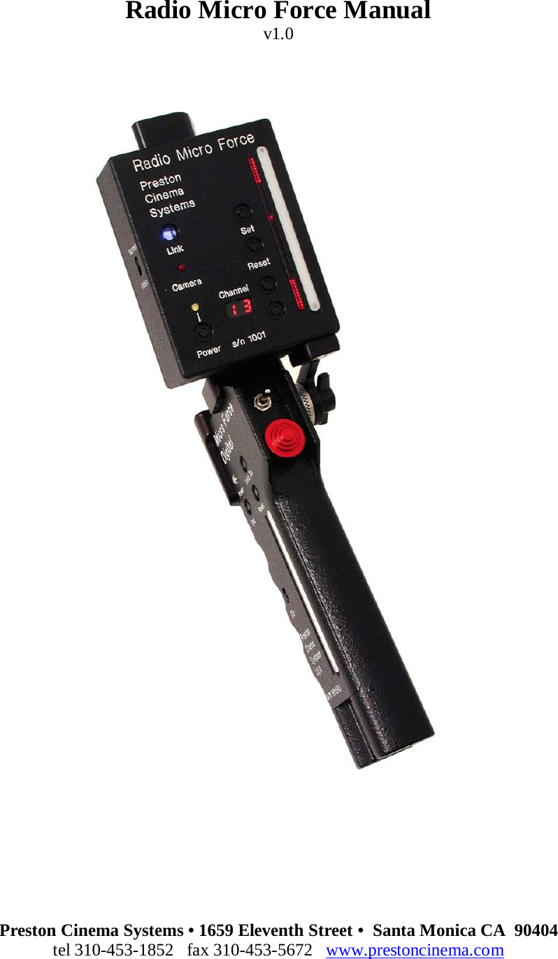
Preston Cinema Systems TR41 2.4 GHz Transceiver Module User Manual Radio Micro Force Manual

Preston Cinema Systems Inc 2.4 GHz Transceiver Module Radio Micro Force Manual

Users Manual 3

Radio Micro Force Manual v1.0         Preston Cinema Systems • 1659 Eleventh Street •  Santa Monica CA  90404 tel 310-453-1852   fax 310-453-5672   www.prestoncinema.com
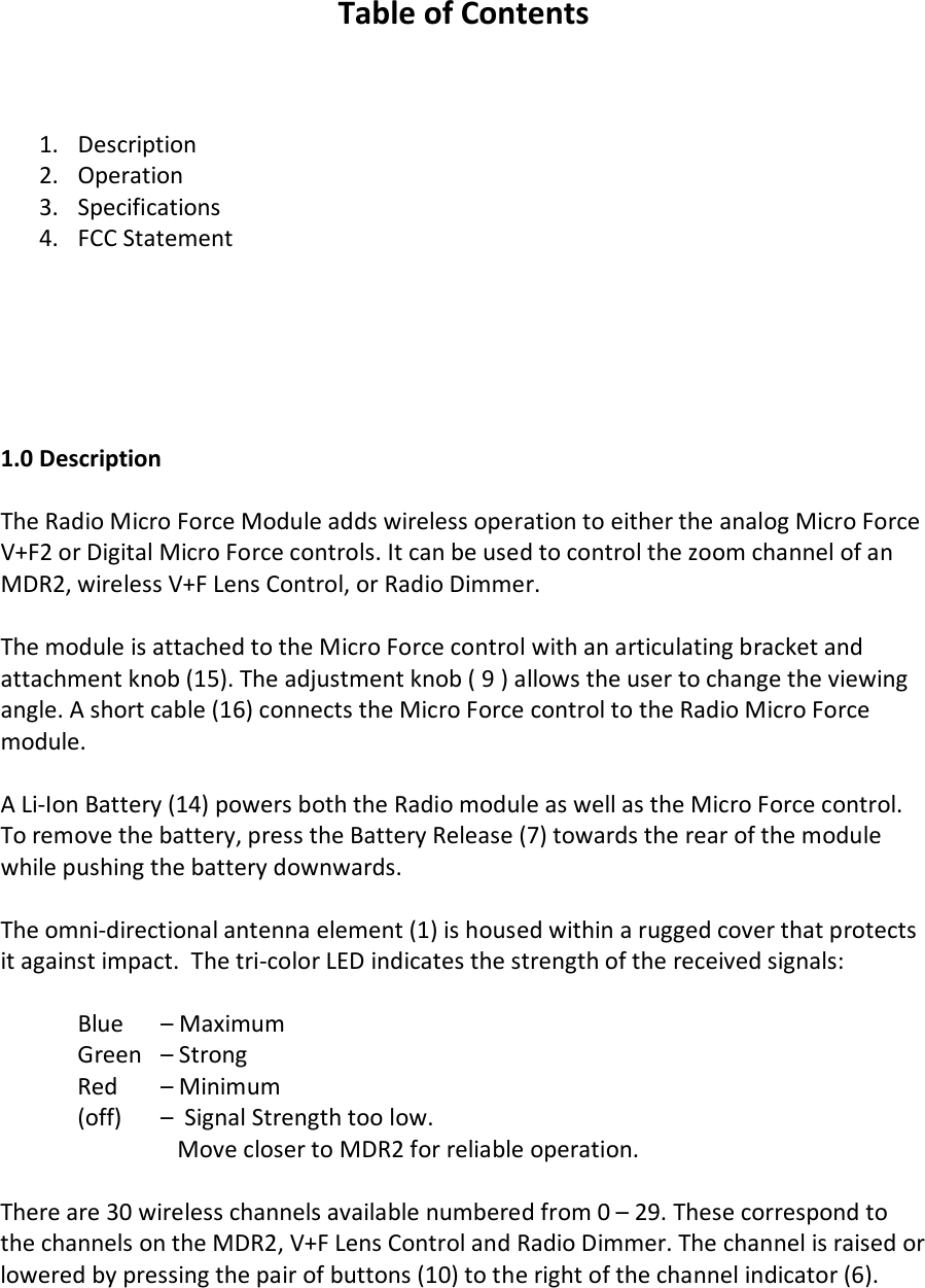
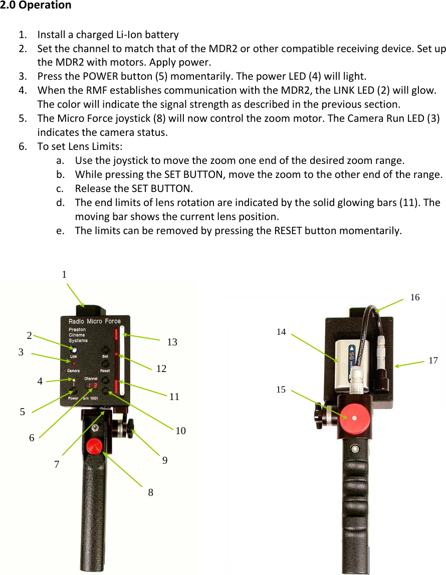
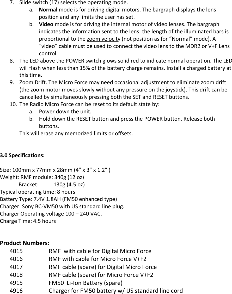
 Table of Contents    1. Description 2. Operation  3. Specifications 4. FCC Statement       1.0 Description  The Radio Micro Force Module adds wireless operation to either the analog Micro Force V+F2 or Digital Micro Force controls. It can be used to control the zoom channel of an MDR2, wireless V+F Lens Control, or Radio Dimmer.  The module is attached to the Micro Force control with an articulating bracket and attachment knob (15). The adjustment knob ( 9 ) allows the user to change the viewing angle. A short cable (16) connects the Micro Force control to the Radio Micro Force module.   A Li-Ion Battery (14) powers both the Radio module as well as the Micro Force control. To remove the battery, press the Battery Release (7) towards the rear of the module while pushing the battery downwards.   The omni-directional antenna element (1) is housed within a rugged cover that protects it against impact.  The tri-color LED indicates the strength of the received signals:   Blue   – Maximum   Green   – Strong  Red   – Minimum  (off)   –  Signal Strength too low.     Move closer to MDR2 for reliable operation.  There are 30 wireless channels available numbered from 0 – 29. These correspond to the channels on the MDR2, V+F Lens Control and Radio Dimmer. The channel is raised or lowered by pressing the pair of buttons (10) to the right of the channel indicator (6).
 2.0 Operation  1. Install a charged Li-Ion battery 2. Set the channel to match that of the MDR2 or other compatible receiving device. Set up the MDR2 with motors. Apply power.  3. Press the POWER button (5) momentarily. The power LED (4) will light.  4. When the RMF establishes communication with the MDR2, the LINK LED (2) will glow. The color will indicate the signal strength as described in the previous section.  5. The Micro Force joystick (8) will now control the zoom motor. The Camera Run LED (3) indicates the camera status. 6. To set Lens Limits: a. Use the joystick to move the zoom one end of the desired zoom range. b. While pressing the SET BUTTON, move the zoom to the other end of the range. c. Release the SET BUTTON. d. The end limits of lens rotation are indicated by the solid glowing bars (11). The moving bar shows the current lens position.  e. The limits can be removed by pressing the RESET button momentarily.                                  1 2 3 4 5 6 11 10 9 8 7 12 13 14 15 16 17
7. Slide switch (17) selects the operating mode. a. Normal mode is for driving digital motors. The bargraph displays the lens position and any limits the user has set. b. Video mode is for driving the internal motor of video lenses. The bargraph indicates the information sent to the lens: the length of the illuminated bars is proportional to the zoom velocity (not position as for “Normal” mode). A “video” cable must be used to connect the video lens to the MDR2 or V+F Lens control. 8. The LED above the POWER switch glows solid red to indicate normal operation. The LED will flash when less than 15% of the battery charge remains. Install a charged battery at this time. 9. Zoom Drift. The Micro Force may need occasional adjustment to eliminate zoom drift (the zoom motor moves slowly without any pressure on the joystick). This drift can be cancelled by simultaneously pressing both the SET and RESET buttons.   10. The Radio Micro Force can be reset to its default state by: a. Power down the unit. b. Hold down the RESET button and press the POWER button. Release both buttons. This will erase any memorized limits or offsets.   3.0 Specifications:  Size: 100mm x 77mm x 28mm (4” x 3” x 1.2” ) Weight: RMF module: 340g (12 oz)               Bracket:           130g (4.5 oz) Typical operating time: 8 hours Battery Type: 7.4V 1.8AH (FM50 enhanced type) Charger: Sony BC-VM50 with US standard line plug. Charger Operating voltage 100 – 240 VAC. Charge Time: 4.5 hours   Product Numbers: 4015 RMF  with cable for Digital Micro Force 4016 RMF with cable for Micro Force V+F2 4017 RMF cable (spare) for Digital Micro Force 4018 RMF cable (spare) for Micro Force V+F2 4915 FM50  Li-Ion Battery (spare) 4916 Charger for FM50 battery w/ US standard line cord          14 16 15
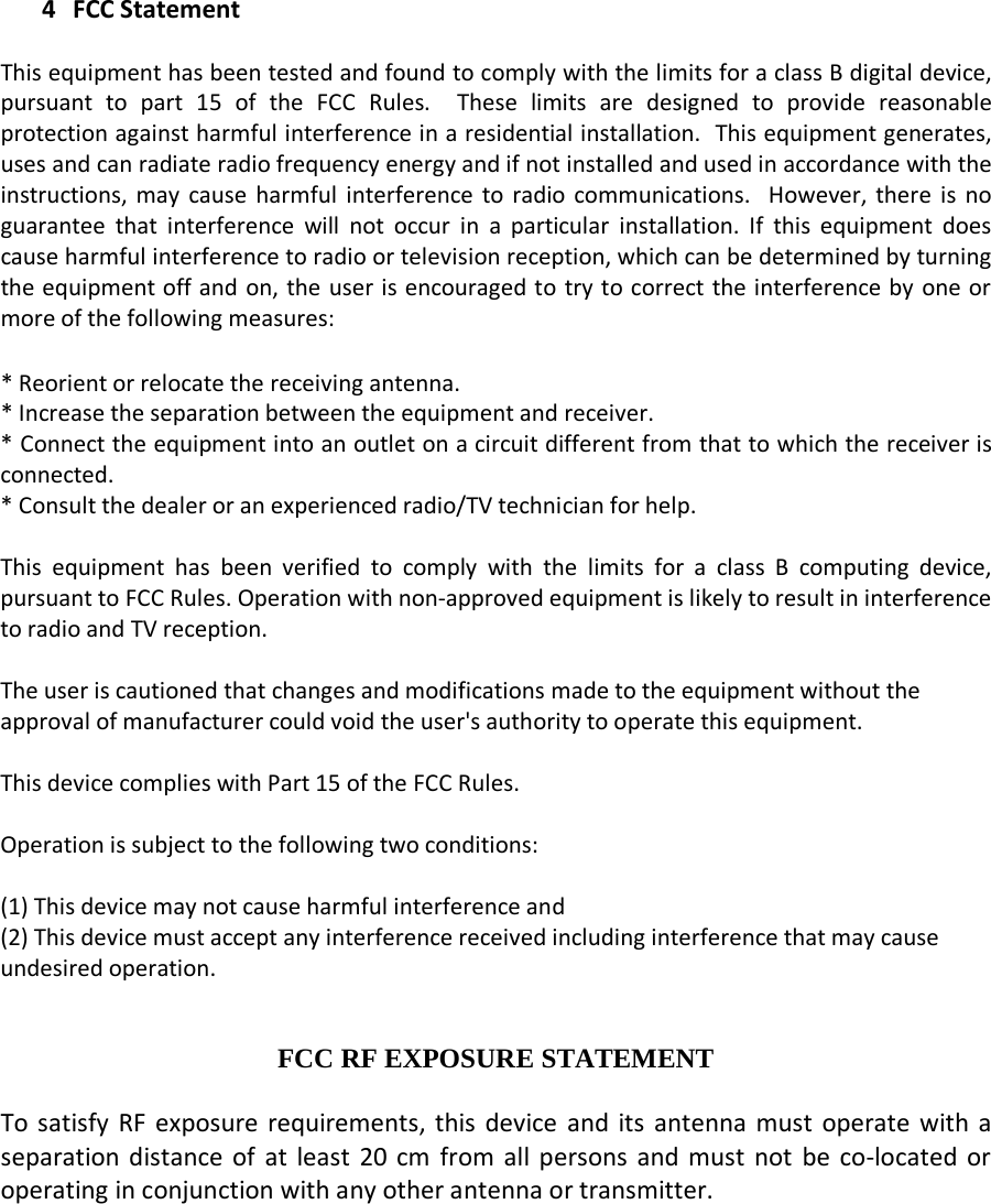
   4 FCC Statement  This equipment has been tested and found to comply with the limits for a class B digital device, pursuant to part 15 of the FCC Rules.  These limits are designed to provide reasonable protection against harmful interference in a residential installation.  This equipment generates, uses and can radiate radio frequency energy and if not installed and used in accordance with the instructions, may cause harmful interference to radio communications.  However, there is no guarantee that interference will not occur in a particular installation. If this equipment does cause harmful interference to radio or television reception, which can be determined by turning the equipment off and on, the user is encouraged to try to correct the interference by one or more of the following measures:  * Reorient or relocate the receiving antenna. * Increase the separation between the equipment and receiver. * Connect the equipment into an outlet on a circuit different from that to which the receiver is connected. * Consult the dealer or an experienced radio/TV technician for help.  This equipment has been verified to comply with the limits for a class B computing device, pursuant to FCC Rules. Operation with non-approved equipment is likely to result in interference to radio and TV reception.    The user is cautioned that changes and modifications made to the equipment without the approval of manufacturer could void the user's authority to operate this equipment.  This device complies with Part 15 of the FCC Rules.  Operation is subject to the following two conditions:  (1) This device may not cause harmful interference and (2) This device must accept any interference received including interference that may cause undesired operation.   FCC RF EXPOSURE STATEMENT  To satisfy RF exposure requirements, this device and its antenna must operate with a separation distance of at least 20 cm from all persons and must not be co-located or operating in conjunction with any other antenna or transmitter.

Navigation menu